HOLIDAY DONATION DRIVE - SUPPORT MSW - DO YOUR PART TO KEEP THIS GREAT FORUM GOING! (Only 36 donations so far out of 49,000 members - C'mon guys!)
×


Gregor
-
Posts
225 -
Joined
-
Last visited
Content Type
Profiles
Forums
Gallery
Events
Everything posted by Gregor
-
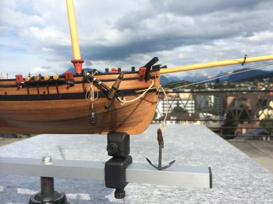
I'm looking forward to new pictures in your log, Toni! Here the bobstay I added yesterday (0.75mm, fully served). It's more than an accessory, it really helps the bowsprit to stay in it's place. Gregor
- 17 replies
-
- 4
-

-
- Sherbourne
- bobstay
- (and 2 more)
-
Hi Tony Somehow I have missed this thread. I searched the term bobstay today when I realised that – with all the forces working in the rigging installed so far – in my Sherbourne the bowsprit began to lift a few degrees. So the very next thing I will do before belaying the backstays is to mount a strong bobstay, served all over. Thanks for initializing this very helpful thread, Gregor
- 17 replies
-
- 2
-
-
- Sherbourne
- bobstay
- (and 2 more)
-
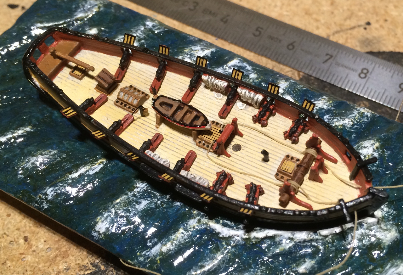
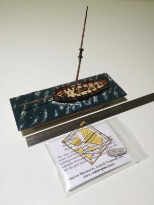
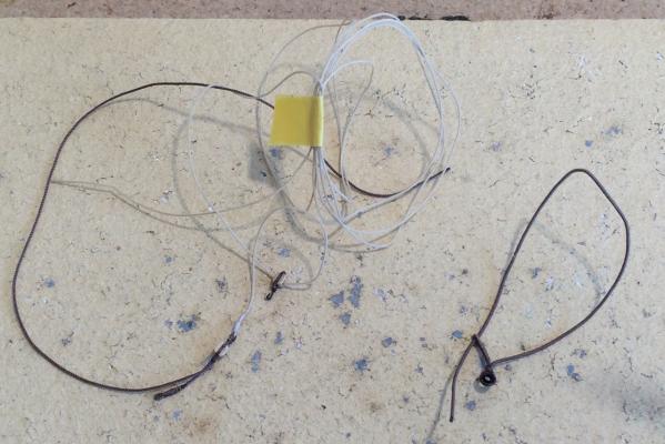
It’s that time of the year: While the reasons for my slow progress are mainly not hobby related, here is one culprit who is stealing some of my Sherbourne time – please meet HMC Dragonfly. It’s a jewel of a resin kit in 1:35 scale from Langton Miniatures. And another small cutter has just arrived, from the same producer: HMC Firefly, white metal7brass in 1:1200 scale. Whenever I think I have a problem rigging the Sherbourne, I have a look at these two and at the super thin fly-fishing threads I found in a local shop, and feel instantly better. More Cheers Gregor

- 210 replies
-
- 4
-
-
- Sherbourne
- Cutter
- (and 5 more)
-
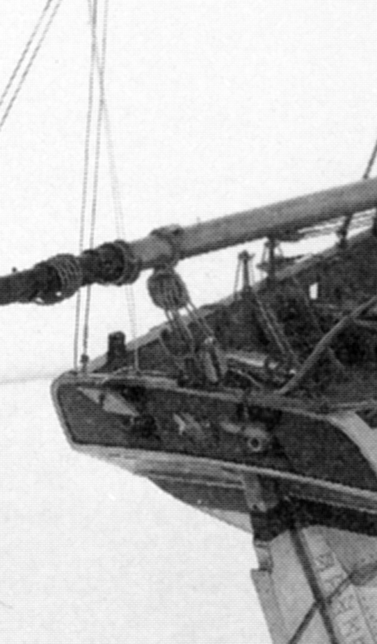
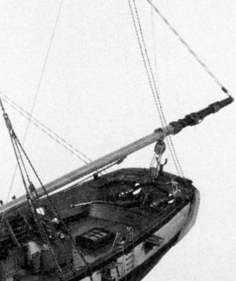
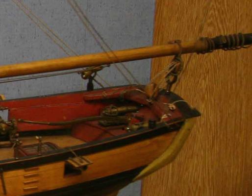
Thank you, Tony and Kester. Yes, the Alert-type of rigging separates the parts rather nicely from each other - my jib halliard chafes at the yard, and that can't be good... But here, for Tony, some pictures of the boom crutch on the (big) model in the Londoner Science Museum (no longer in display), from Petersson. This model was the inspiration for my modernization project, and I tried to make a crutch resembling the one shown on the Sherbourne plan. My crutch is made from bent (but not flattened as in the model above) brass wire, soldered on another piece and a washer, placed in a hole drilled in the taffrail. I hope that helps. Gregor

- 210 replies
-
- 3
-
-
- Sherbourne
- Cutter
- (and 5 more)
-
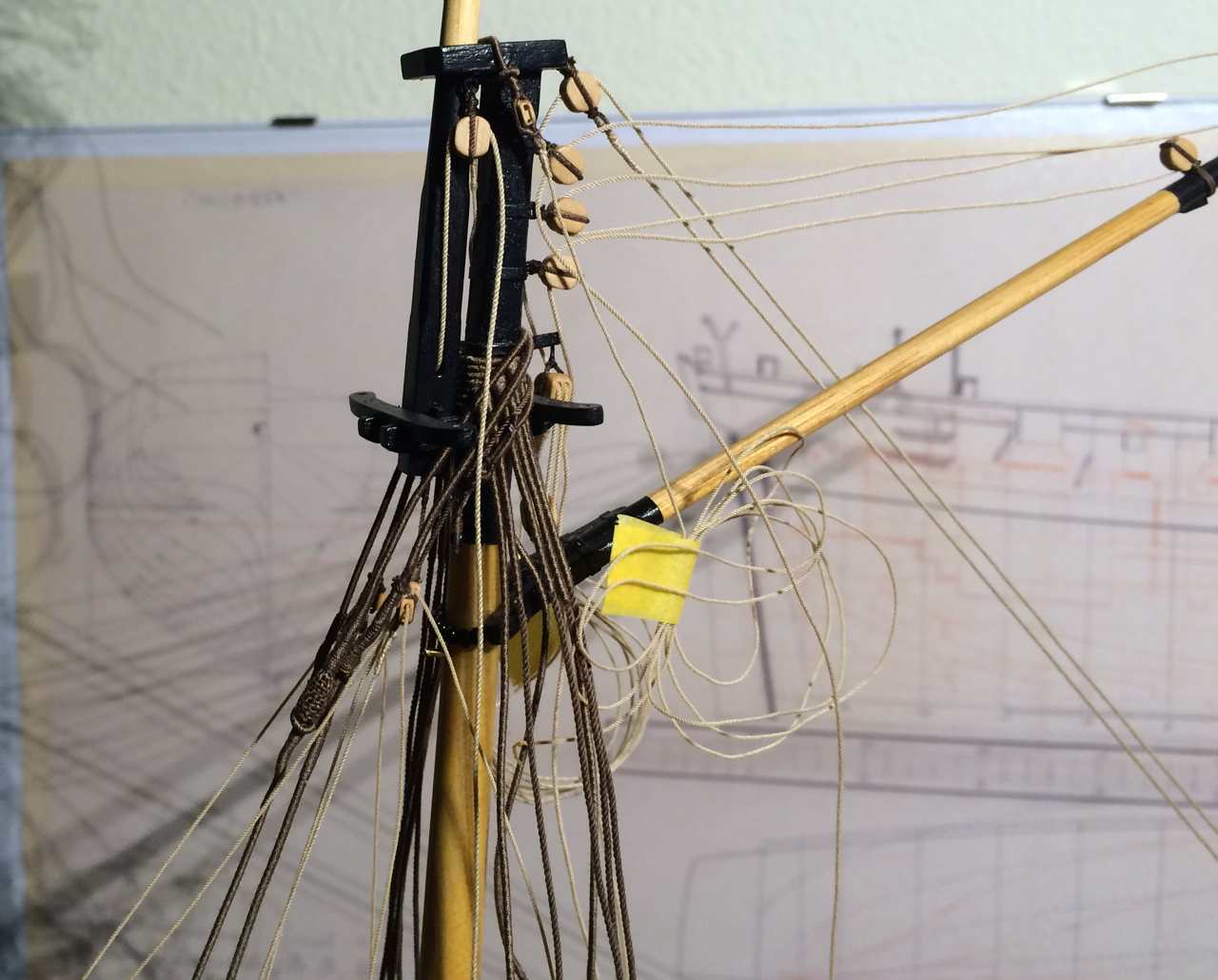
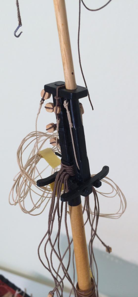
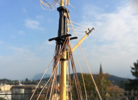
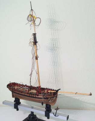
Progress is very slow at the moment, and I’m seeing some difficulties: While the shrouds and stays are in place, it’s very crowded in the top. This is a consequence of my rather naïve disregard for plans. I have built all the parts after Petersson and picture sources; but I have forgotten that these parts have to fit together in a working system. You can see that the stays loop around the mast rather narrowly; therefore the blocks for the Jib Halliard are very near the mast and leaving only little space for the yard… Well, it’s still fun, and I’m learning a lot, and my admiration for the builders of sailing ships is rapidly growing. Seen from across the room it doesn't look so bad, after all. Cheers Gregor

- 210 replies
-
- 5
-
-
- Sherbourne
- Cutter
- (and 5 more)
-
Beautifully done, Kester, thanks for showing. Gregor
-
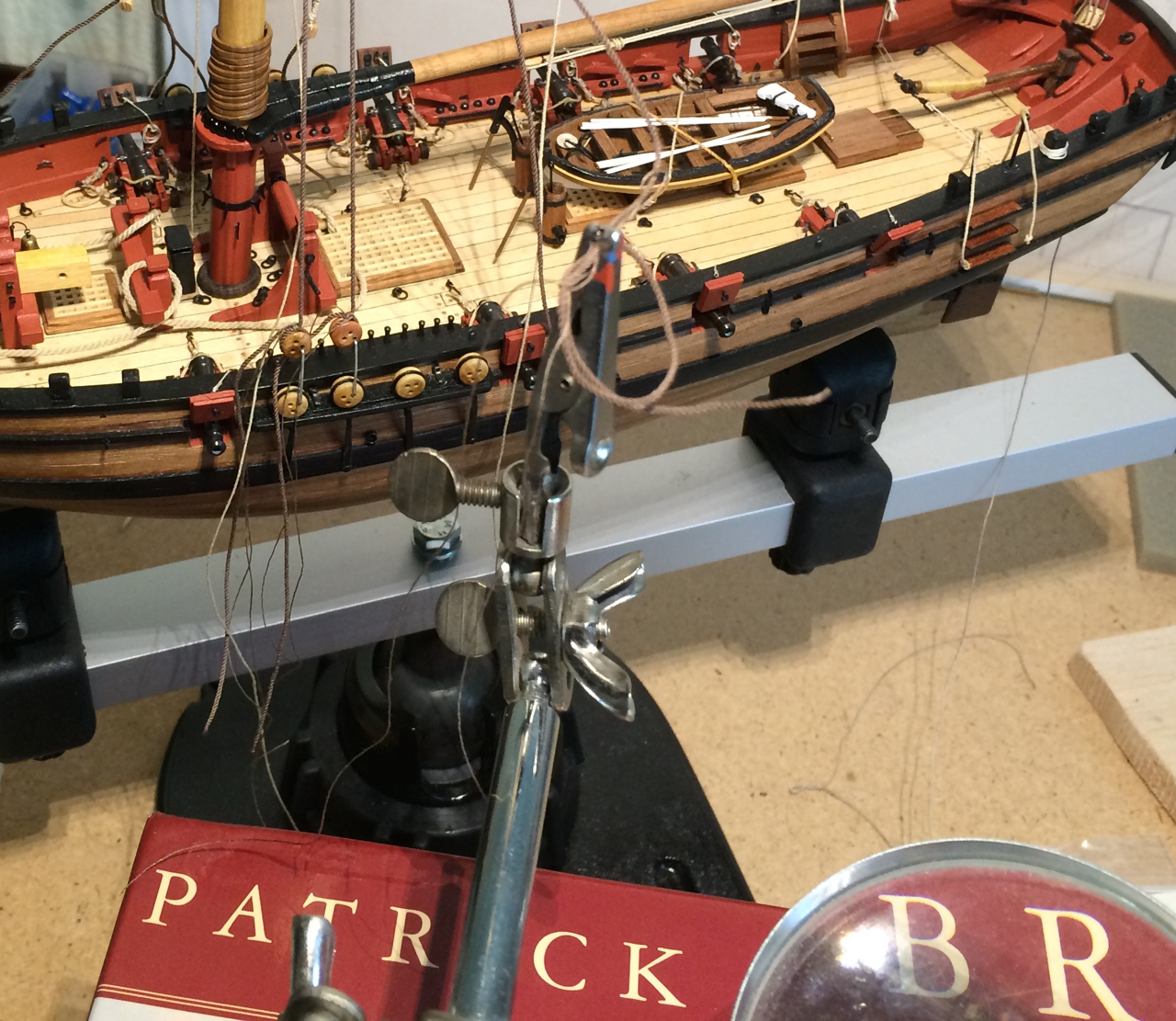
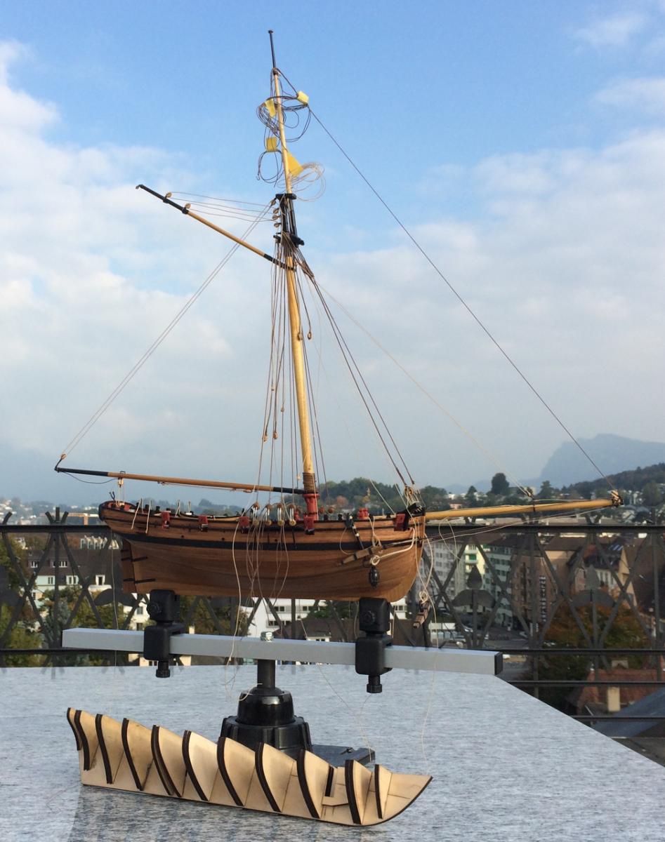
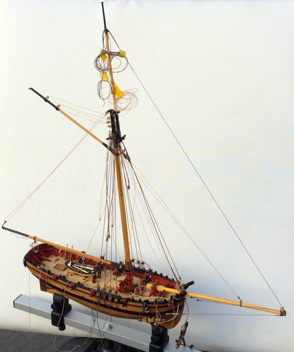
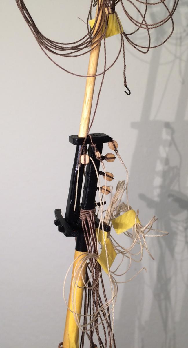
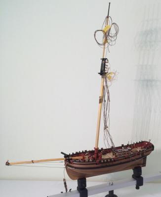
It has been a while since my last post. But now that it is the Week of the Cutter on MSW here a few pictures – there is some small progress to show. It’s still crowded in the top. But it is better once the shrouds and stays have some tension. Still, nothing is glued or belayed definitively. Shrouds and deadeyes are in place. There is a simple slipknot with three turns that holds the deadeyes in position; it’s movable, so I can now adjust an even tension. Lucky me, I had a stack of suitable books handy to lift my third hand so I could make the slipknots outside of the model. Once I feel comfortable, I will put in the lanyards. This is the detail I like most: The Five-hole-deadeye is in place, together with the preventer stay. And that is the whole ship; it has grown a little. And finally, one of the reasons for my slow progress: I made the skeleton for my next project. It’s the lovely small French schooner La Jacinthe (1823) after Jean Boudriot, scaled down from 1/48 to 1/64. I will finish the Sherbourne before I glue the bulkheads of the Jacinthe, I promise. Cheers, Gregor


- 210 replies
-
- 8
-
-
- Sherbourne
- Cutter
- (and 5 more)
-
Thank you, Chuck, for answering even basic questions; that’s very generous (and helpful). For all of you who would like to work with a laser cutter: Search for universities with an open lab policy. In Switzerland, where I live, and in Germany they are called Fablab; there are a lot of them open to the public, and there you can work with their machines, often under supervision. I was twice at our local fablab already, once to laser parts for gun carriages (made after Chuck’s design), and once to cut bulkheads for my next project. No scroll saw and no sawdust in our apartment, but it’s good for the plywood parts to wait outside a few days to loose the smell of burnt wood and glue. I will follow this project closely, because I dream of building a bigger and more detailed cutter than my small Sherbourne one day. Cheers, Gregor
-
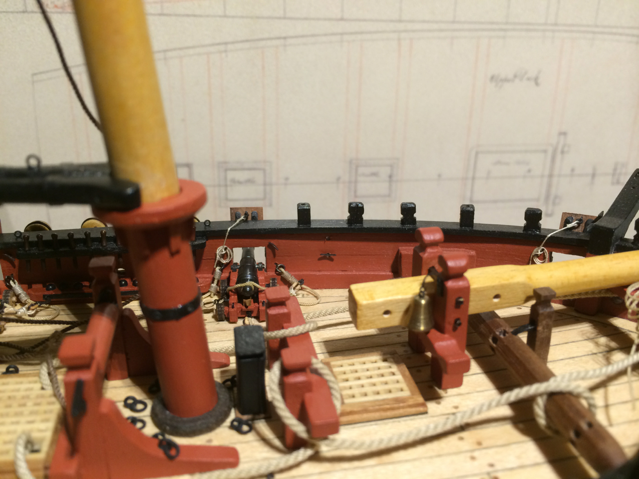
And sorry, Nils, there will be no sails. But now that you are asking, I will give it one last try (the other attempts to make sails were binned a while ago, together with the desire to make them). But I will add sheets and tacks for the square sail, their blocks will hang at the clueline blocks near the yard; I just made the necessary two holes and belaying points for the tacks forward of the first guns. They should be a little more towards the bow, I guess, but then they would be in conflict with the anchors. Similar to the arrangements for sheets and braces at the stern, there are eyebolts outside and a belaying point inside the hull. And because I saw several models with braces for the topsail yard (Petersson is showing only counter braces towards the cranse iron), I will add them too (there are two belaying pins available for them at the stern, the flag halliard will have to go to a small ring already there). Cheers, Gregor

- 210 replies
-
- 5
-
-
- Sherbourne
- Cutter
- (and 5 more)
-
Sorry, Clare, for the delay (and many thanks for the kind words and al the likes I received lately). And yes, the Red is Red Ochre from Caldercraft. But beware, it's (correctly, I think) not a brilliant colour. On my pictures it seems often much redder than it really is. As an alternative to acrylic paints you could think about working with enamel paints - Dirk (Dubz) uses it for his Sherbourne, with a stunning finish. Good luck Gregor
-
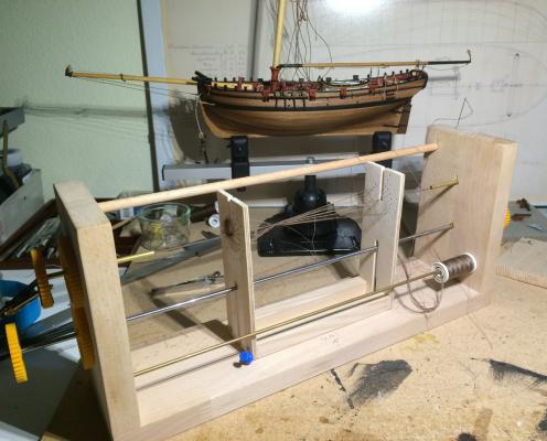
Hi Pat Thousand thanks for showing your jig! It came just at the right moment – here is what I made based on your version: I've made a link from my build log to this post. Thanks, Gregor
-
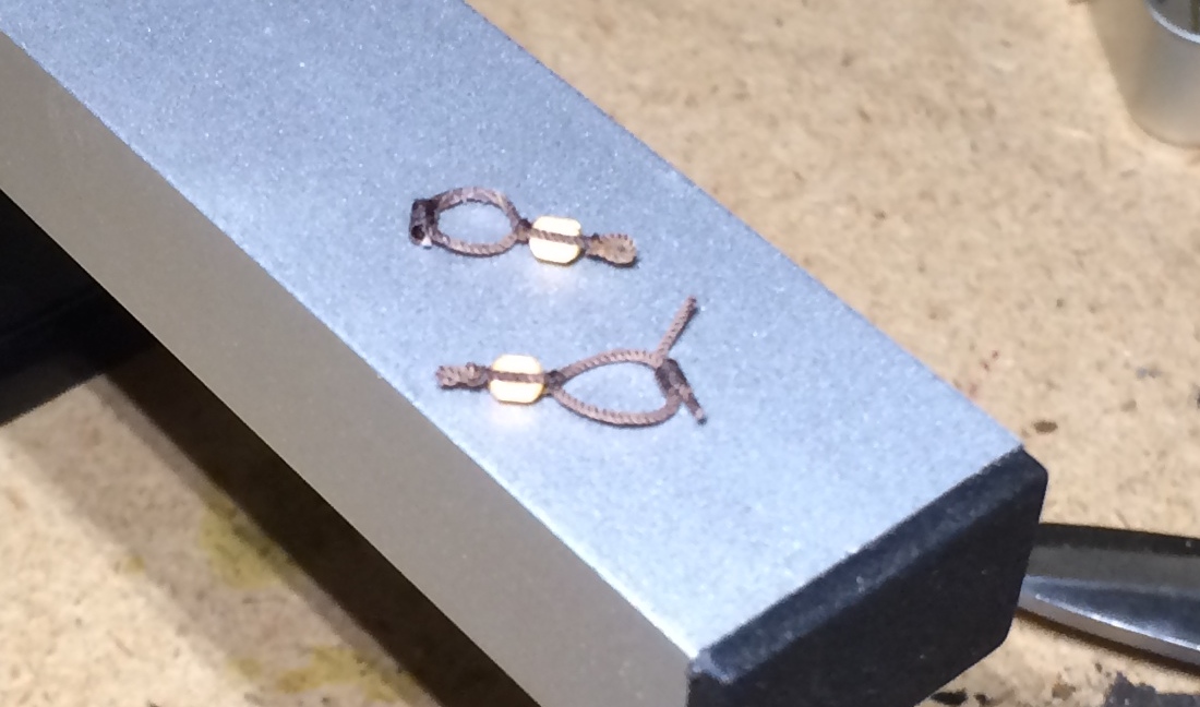
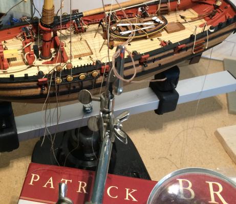
… said by the man who led me on that path! Maybe I should begin another project, just to let you overtake me. Just at the right moment I found a jig by Pat (Banyan) for a mouse. This I adapted or my serving machine. The simple jig can move right and left, so I can continue serving after weaving the mouse. The bigger mouse took 19 horizontal threads, the smaller 15. It worked fine, once I figured out how to do it (it took a long time, frayed nerves, some noises – you know what I mean). I painted the pear shaped wooden former black; this gives me a depth effect – a pleasant side effect of my imperfectly loose weaving. Now I really have to take a break, a beer… Cheers, Gregor

- 210 replies
-
- 3
-
-
- Sherbourne
- Cutter
- (and 5 more)
-
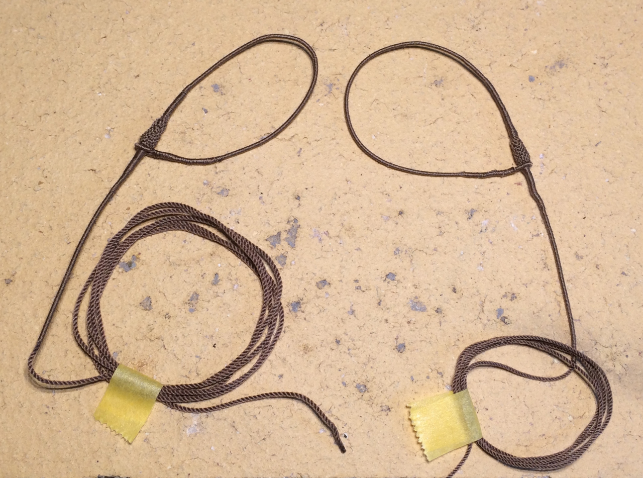
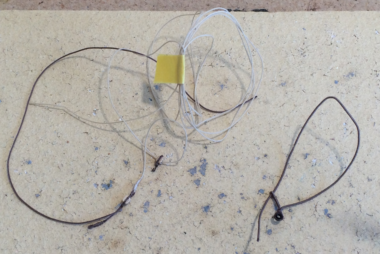
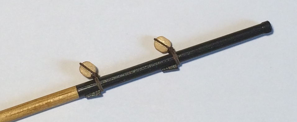
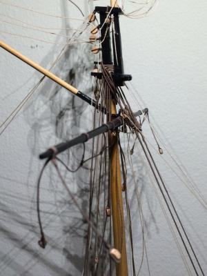
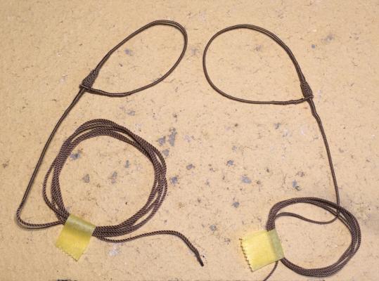
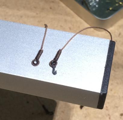
Antony and Dave – you are flattering me (it feels good, I admit). There is really no big story to tell; I’ve spent the last few weeks preparing parts and pieces (and sometimes throwing them away again). I spent many hours with the serving machine I’ve made earlier. Here an example: The sling for the stay sail, which will go around the mast after the stays and the hanger for the square yard, shown on the right. The stay sail halliard has already been bent on. The next great challenge will be the fitting of all the parts in the crosstrees, where it is already crowded. This is mainly because I just “shrunk” the masts to fit Sherbourne’s small hull, when the shrouds and stays (which are not yet here) do not shrink to the same proportions… My biggest mistake so far was that I glued on the cap before bending on the shrouds. That made the job unnecessarily challenging.But now that I’ve put together all the prepared lines, I see there is some progress. Still missing are the main and preventer stays with their mice – another thing that lets me believe that Petersson’s model has a very much younger rigging added later: There the main stay is simply spliced together. Cheers, Gregor


- 210 replies
-
- 10
-
-
- Sherbourne
- Cutter
- (and 5 more)
-
Just a short observation regarding black dying of textile fibres – this was a tricky business before the nineteenth century (and it’s the same with ink on paper). Many a contemporary rigging would no longer be here today if dyed black with ink, which was a very common method for making black threads. In the state archive where I work we keep many charters from the last ten centuries where we see black (ink dyed) threads that hold the wax seals disappear because of their chemical properties (every inkmaker used his own recipe), while other colours (based on minerals) keep well. The acid in the ink “eats” threads (and paper), but, depending on luck and the various recipes, not every black thread is afflicted by this problem. This might be one reason there are not so many models with contemporary black rigging lines today. Cheers, Gregor (Well, the oldest charters don’t have treads on the wax seals yet, and it’s ink on parchment, so they're keeping quite well).
-
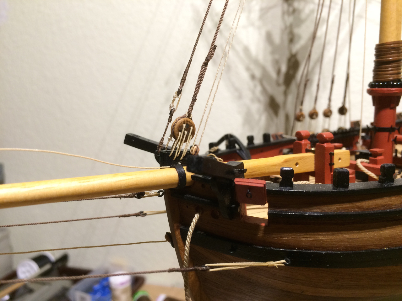
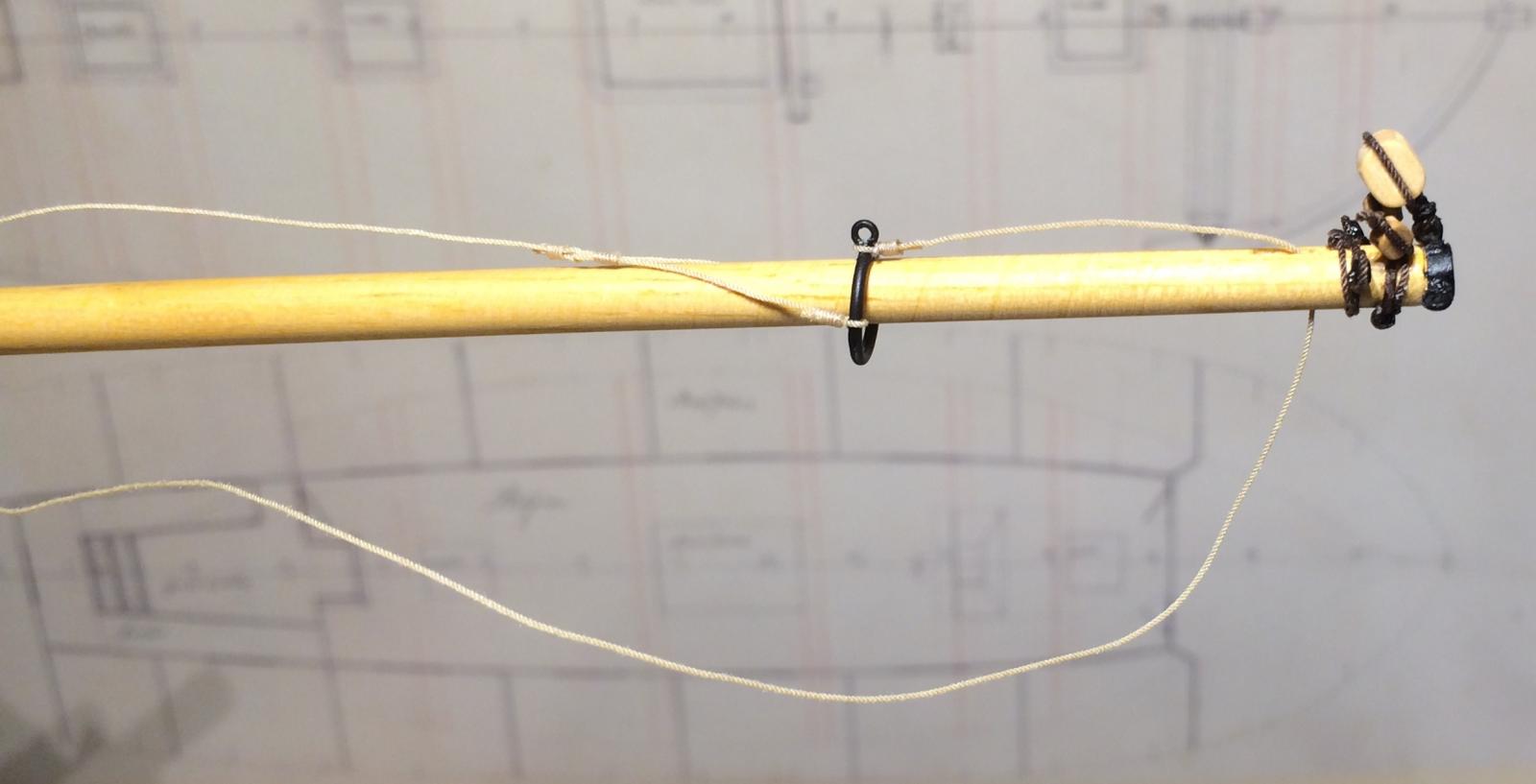
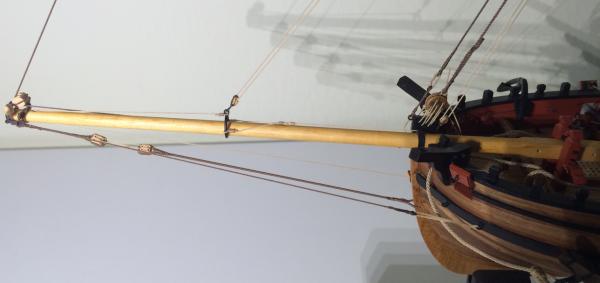
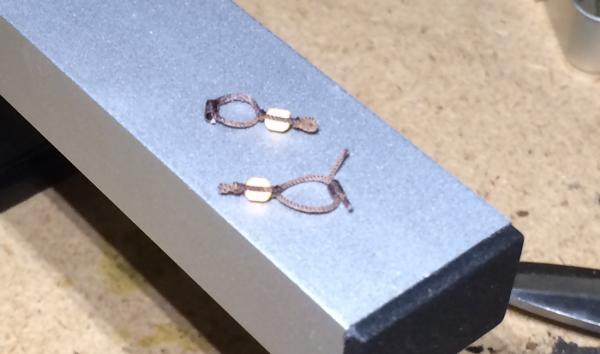
I’m looking forward to see your seizings, Tony. After showing my “tubes”, I got a wonderful tip from a German modeller (which I will try to explain with the example of the new bowsprit guys I’ve just made): The loose end of the 5mm thread which goes around the parral bead was cut so that the three strands it is made of are of different lengths. The difference this makes is easy to see on the picture (the old tube is on top). Diluted PVE keeps the seizing in place after every step. With the cotton thread I made a simple sling as near at the bead as possible, used one end for the seizing and the other end to close the gap towards the bead. Of course, this technique can be perfected – my fist step will be the cutting down of the old bowsprit guys. Cheers, Gregor
- 210 replies
-
- 5
-
-
- Sherbourne
- Cutter
- (and 5 more)
-
Thank you all for the likes and the comments, Kester and Tony. For the seizings, Alexander (who is building a wonderful Sphinxs and whose rigging threads I'm using) pointed out to me in a German forum a method for "less-tube-like" seizings: here is the link to his MSW log and his seizing and splicing method, which I will try. As for the rigging: At the moment I will follow Pettersson only - I learned that either you should have a deep understanding of what you are doing, rigging-wise, or at least a plan. So my plan is to make a model of the model that was the model for Petterssons drawings. But I'm sure I will find a timberhead or two for additional lines later on... Gregor
- 210 replies
-
- 2
-
-
- Sherbourne
- Cutter
- (and 5 more)
-
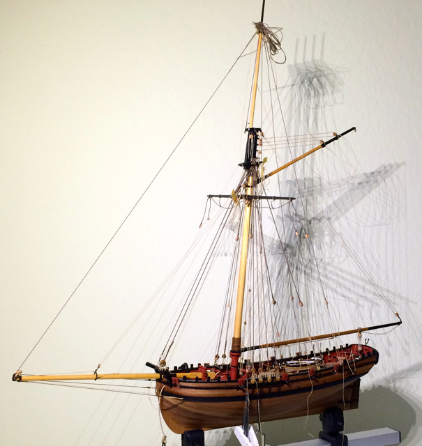
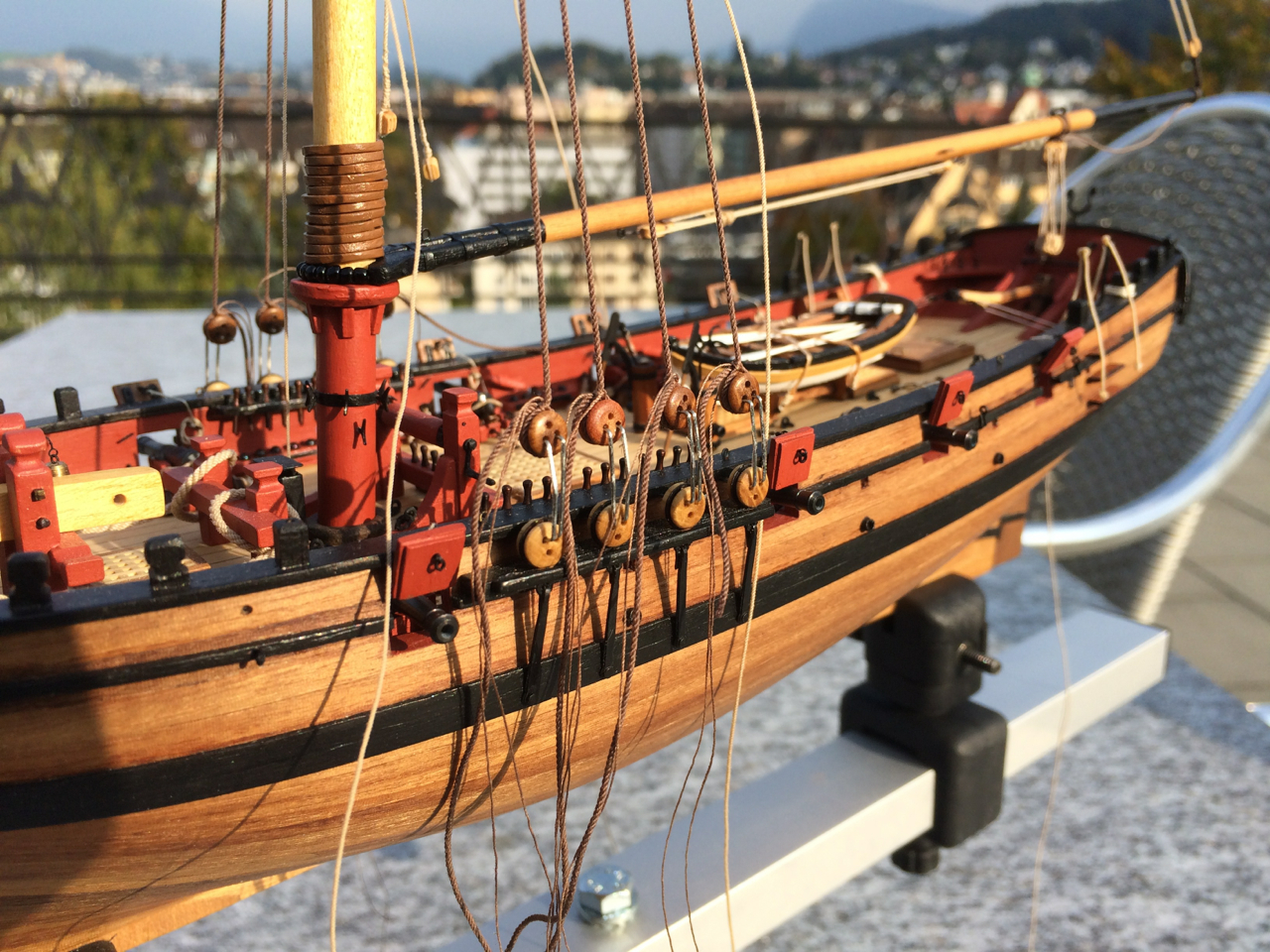
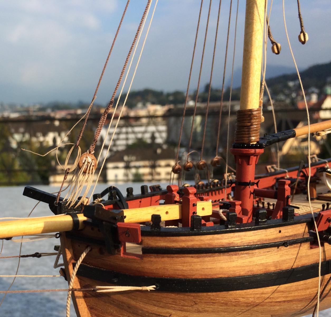
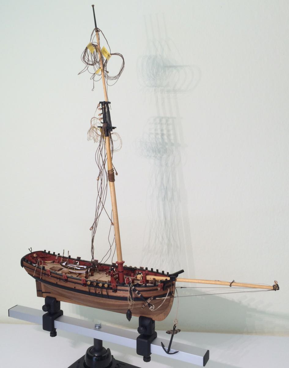
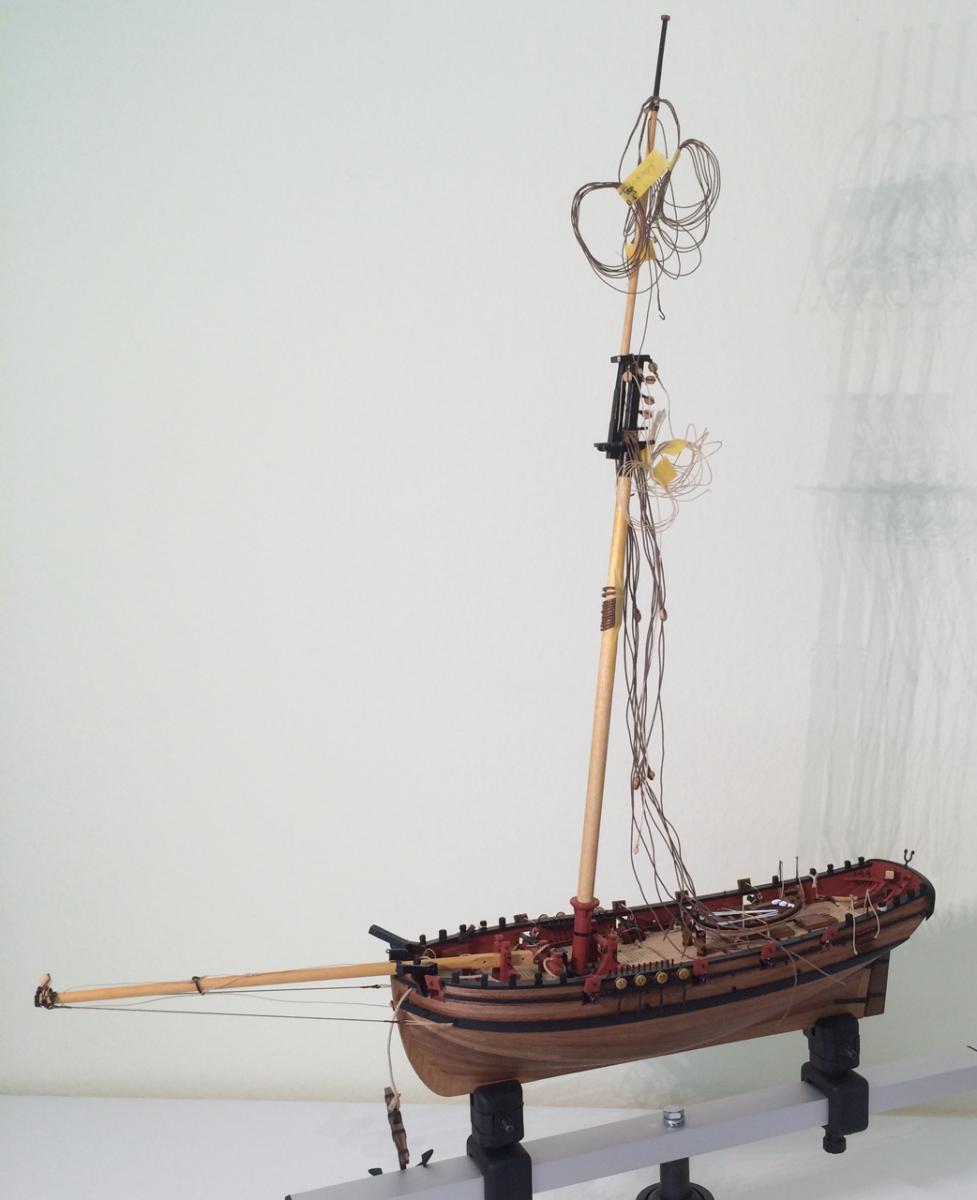
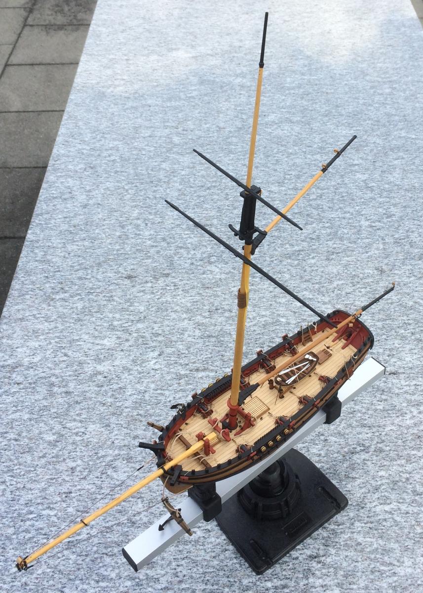
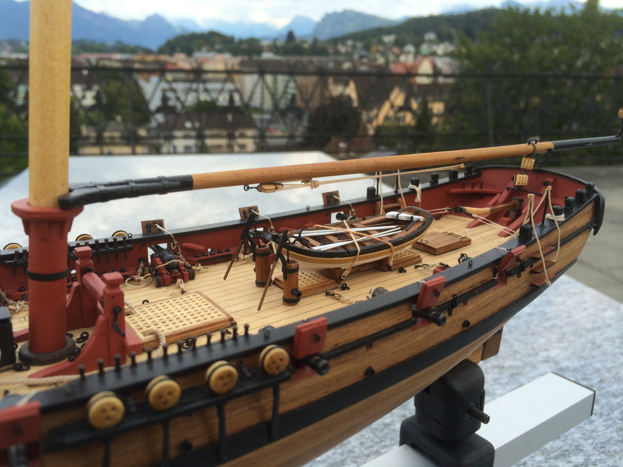
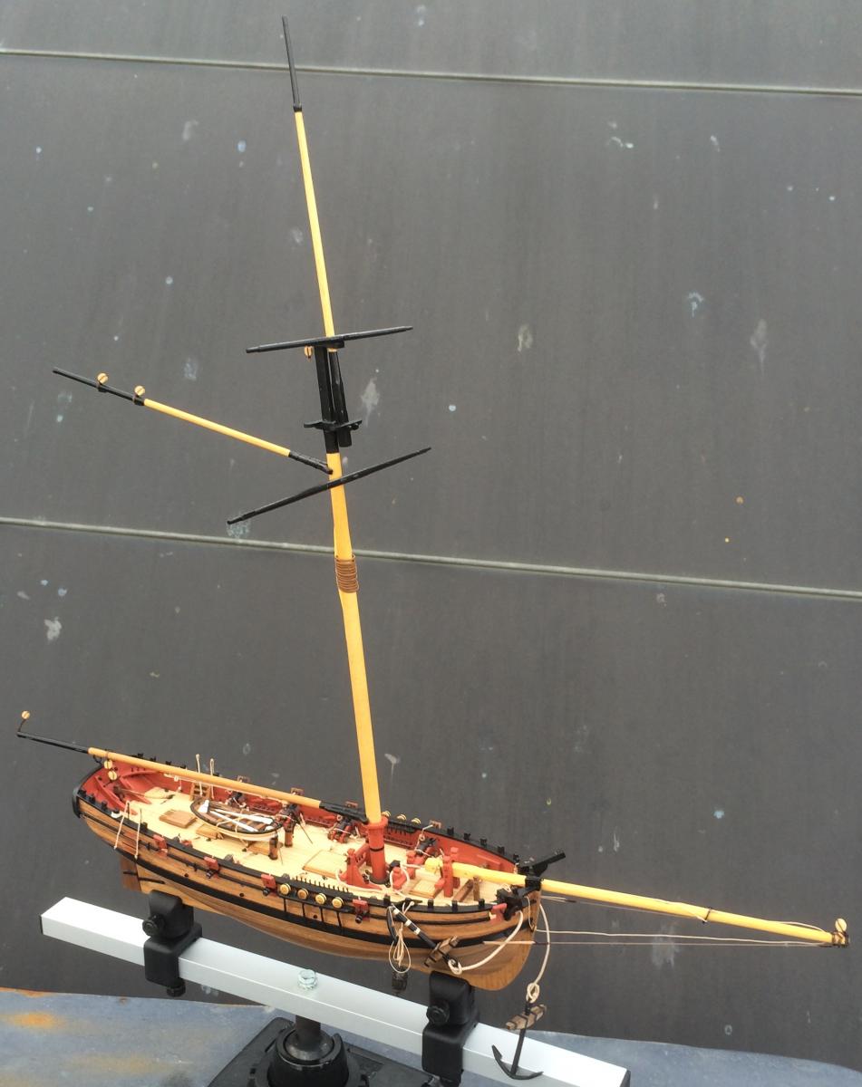
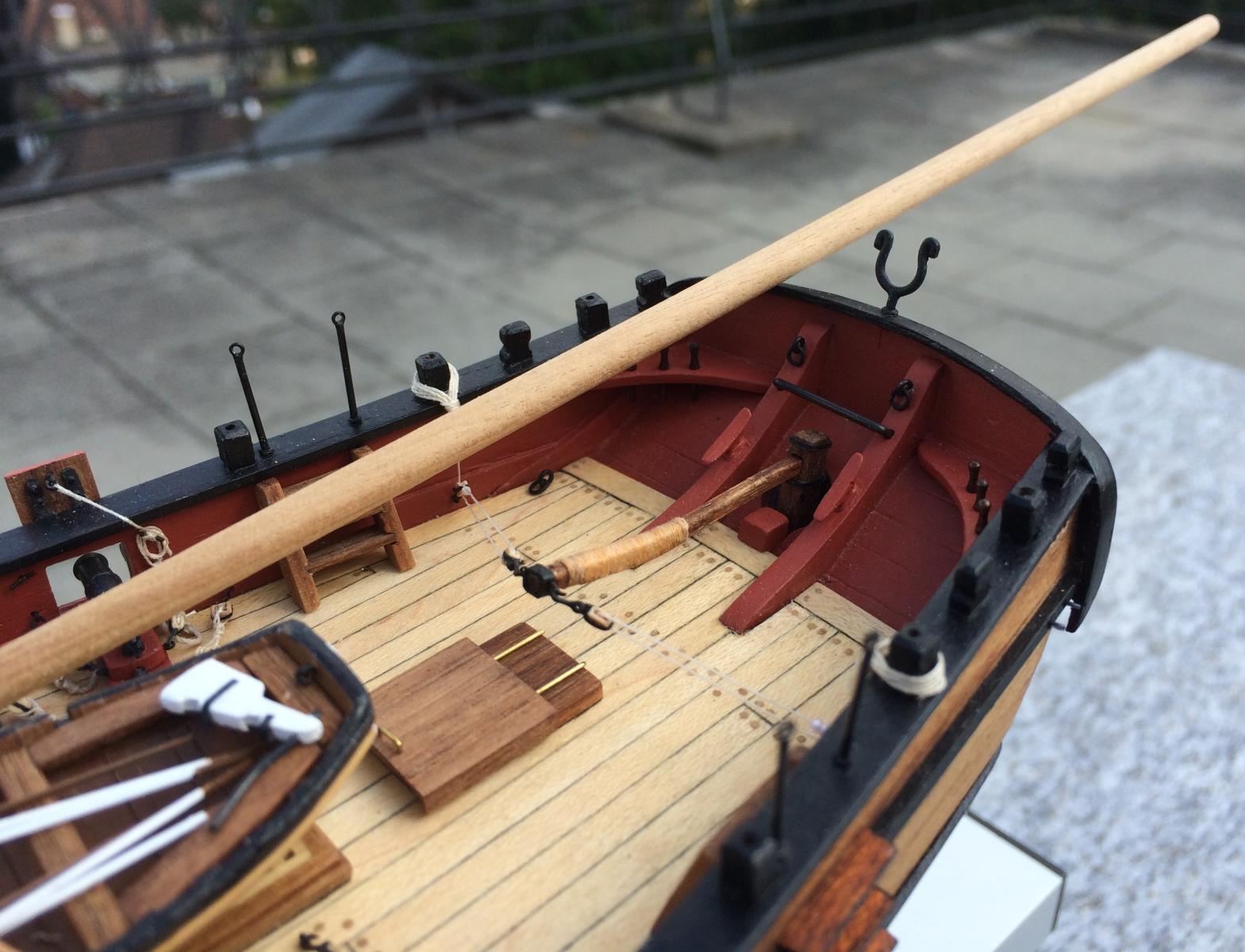
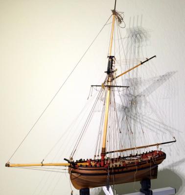
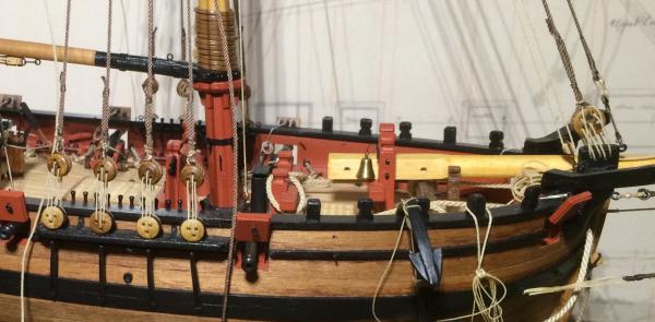
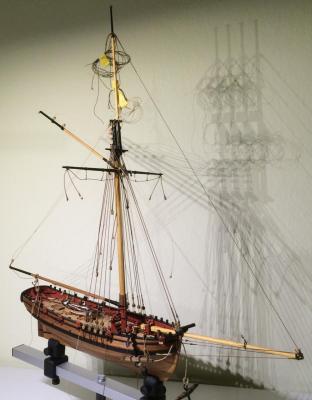
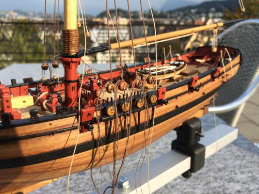
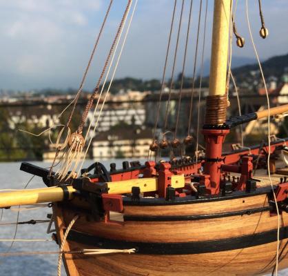
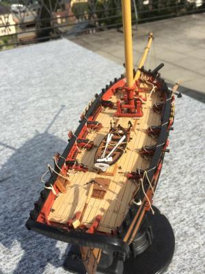
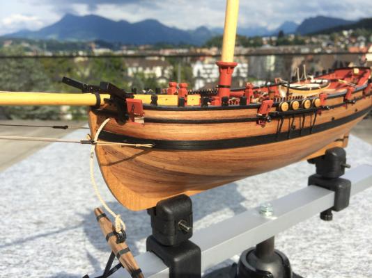
That’s how the deck is looking now. Making a buoy was especially time and nerve consuming. Mine looks much battered, so I like to explain that this item is one of the original pieces of equipment of HMC Sherbourne I in 1763 and has seen 23 years of service, improbable as this may seem… It was rather difficult to make pictures outside today, but I absolutely wanted to share my first look of a “complete” cutter – without the rigging lines, of course. Many details need to be prepared before assembling. I think I will follow Kester’s log to do that. One of the small details will be a proper fiddle block. This one was made from a 5mm and a 3mm single block glued together, not perfect. I wonder whether it would be better to simply lash two blocks together, an alternative proposed by Wolfram zu Mondfeld, but one that I can’t find on NMM’s models. The brown things taped to the mast are the mast rings, which I made from brass wire, soldered and filed into shape. As there will be no sails, they should at least lie properly, and I thought paper rings too light. I have to admit I’m quite pleased with the model that is standing for the first time complete with it’s impressive spars. This will give me the necessary boost for all the other small things that are to be prepared before anything can be glued on definitively. Cheers, Gregor


- 210 replies
-
- 11
-
-
- Sherbourne
- Cutter
- (and 5 more)
-
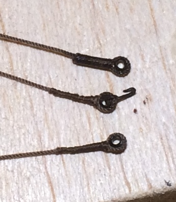
After a long absence it’s time for an update: nothing significant happened (modelling wise), but I learned a lot, trying to bend blocks to spars and making seizings. The so-called ZIP-seizings are easy to make, but once in place, they look like what they essentially are: tubes. The thinner the threads, the better they are looking. They are ok on the inhauler/outhauler (0.4mm, seizing 0.1mm). On the bowsprit guys (0.5mm, seizing 0.1mm) they look somewhat wrong. But they helped a lot making the thimbles (the smallest parral beads I could find locally). For the rest of the blocks on the masts and spars I will use Jay’s (modeller12) method.

- 210 replies
-
- 5
-
-
- Sherbourne
- Cutter
- (and 5 more)
-
Great, Kester, your bosun brings life to your model! Before you go off to your cottage and the secret project; a question about Sherbourne: What do you think about braces for the gaff? I found only one (younger) contemporary model in the NMM collection with braces, but find them often on schooners. Enjoy summer, Gregor
-
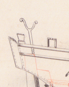
Just an observation (I hope I haven't missed it before): Alert from 1777 has a symmetrical arrangement at the stern (unexplained in Goodwin's book) that looks like wooden boom supports. After a quick browsing through the NMM collection I got the impression that these were not essential parts, because they are rarely shown on contemporary models. Gregor
-
Here is my attempt to make a boom rest. There is one to be seen clearly on the Science Museum cutter (here the link, provided by Jay: http://www.modelships.de/Museums_and_replicas/Science_Museum_London/Ship_model_naval_cutter.htm), in Peterssen’s book. Gregor

-
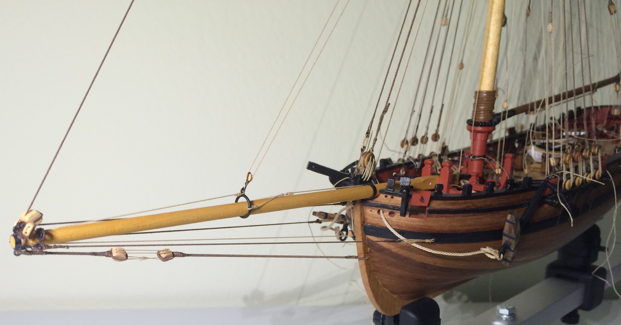
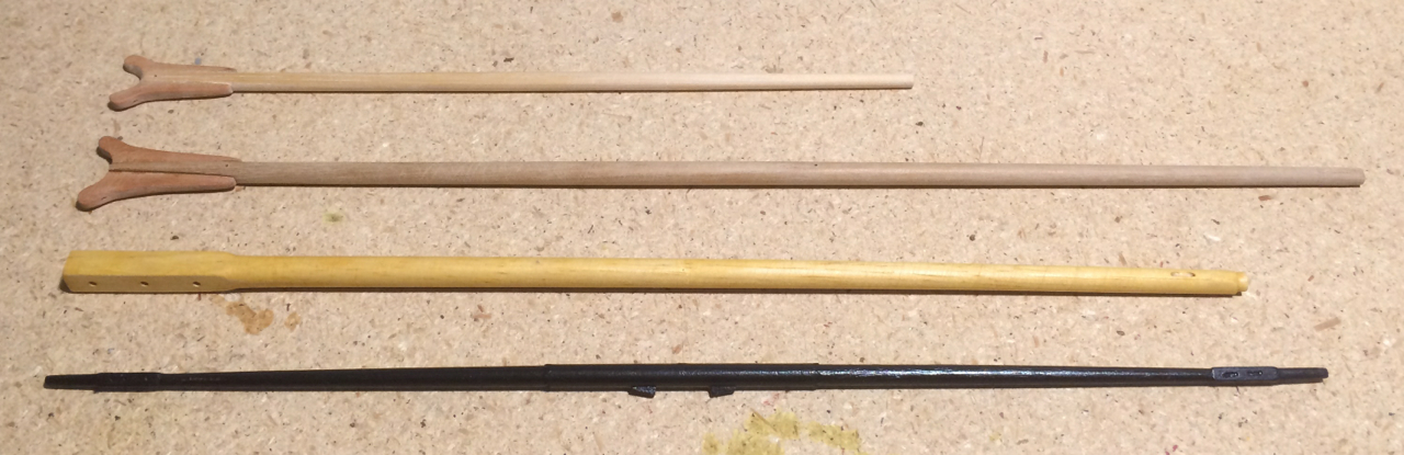
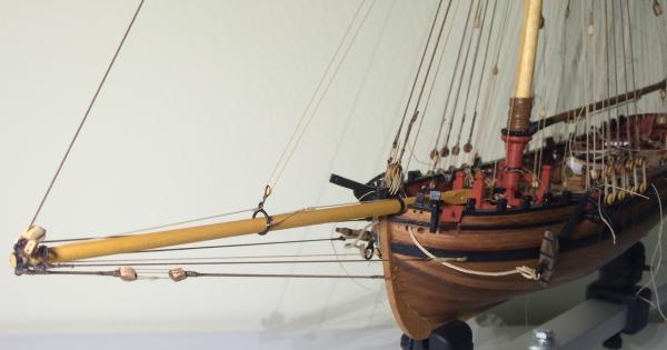
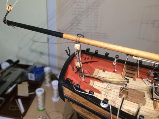
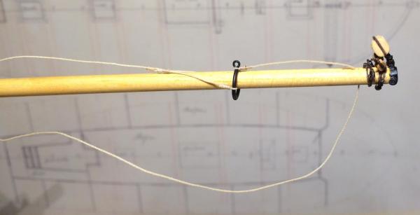
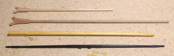
The slightly premature publication of my rigging plan had some positive effects. I’m still working on it, but learned a lot. It even helped me understand better other logs, Kester’s prominently among them (I wish I had understood more when I started, especially his discussion of Peterssen’s modernised rigging, but that is all part of the learning process). Following Peterssen, I had to make a new square sail yard, with two sheaves on each end. I also, like Kester, made a new boom from a 5 mm dowel, since the old one looked very weak, compared to the other spars. And, after ripping out and repositioning the bowsprit, it too had to be remade: Painting the bowsprit was not my brightest idea, so the new one has a light oak varnish and is less tapered towards the outer end. Modelling-time was rare before my upcoming holydays, so there’s not much to show (I updated the data in post #164). For all who feel they need some motivation or simply something enjoyable to read or to look at, you can legally download “King's Cutters and Smugglers 1700-1855” by E. Keble Chatterton on the Project Gutenberg website. The pictures alone are worth a click or two. Enjoy, Gregor
- 210 replies
-
- 2
-
-
- Sherbourne
- Cutter
- (and 5 more)
-
Iain, I agree with Tony. I used a sharp blade and a metal ruler to cut a rough outline only. Then I used sandpaper and a sanding block to get the curved shape of a plank. I would never dare to cut at a plank already glued on (I forgot most of my latin during the last thirty years). I left the space für the stealers to fill in later - I hope you will be more careful with the geometry than me, a thing I have always trouble imagining in three dimensions on a hull. I made a "paper stealer", pressing a thin paper to the planks surrounding the place where the stealer has to fit in. That will give you a rough template for the walnut stealer plank. Good luck, Gregor
-
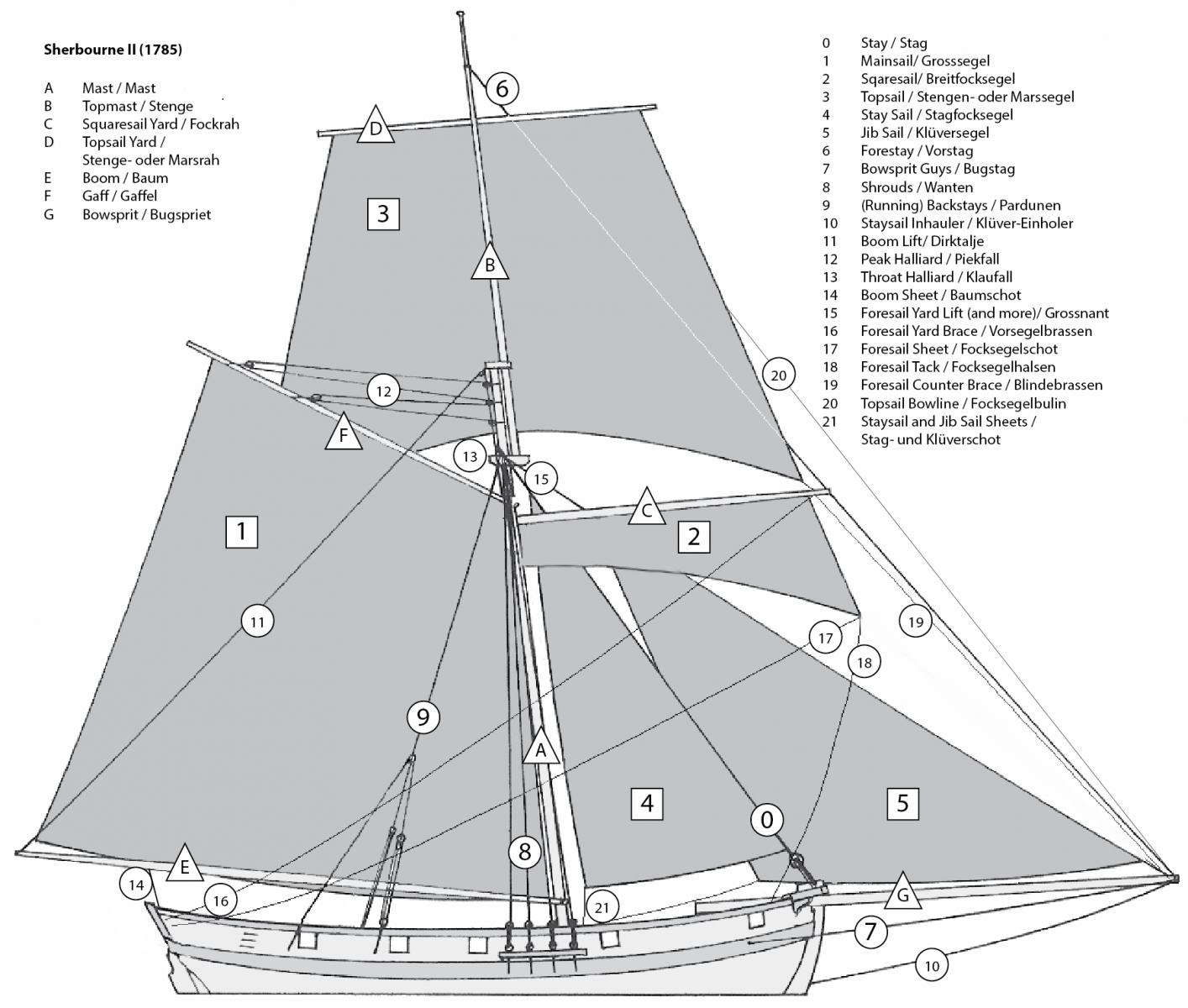
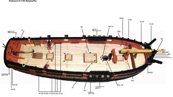
Here it is, my belaying plan. It started with George Bandurek’s list, and then I tried to match it with Petersson’s drawings. There were big differences not only in the kind of rigging, but also in the use of terms, so I decided to draw a picture. I photoshopped Petersson’s cutter into something resembling my Sherbourne, added some sails and rigging details or moved them around; and gave each part a name. Doing that in two languages made this a true Babylonian task. But this was necessary to clear my brain and complete the rigging list. Sherbourne Rigging_v2.pdf This list was then used to draw a belaying plan for my model. I was very relieved when I saw that there are even more belaying points than necessary! As I’m still unsure whether to make (furled) sails or not, the amount of lines might be reduced later. Of course, one can always add more lines… But these are the parts that Petersson shows in his drawings, minus the Burton tackles. It took quite some time to make these plans, but it was the only way for me. I cannot do that in my head alone. And it was also a test: Petersson doesn’t show a belaying point for the forestay, and his cutter has a modern windlass with many belaying pins, therefore I had to find alternatives. Peterssons cutter is shown without sails, and I’m confused with some details: He shows a topsail bowline. Can this be right? Do topsails have bowlines? In my list at the moment I have bowlines for the lower sail (on Petersson’s model there are bowlines (?) coming from the topyard). This is hard to decide for a mere landsman. Consulting the plans of the Pickle online was very helpful – it seems that Caldercraft’s younger kits have generally thinner ropes (the main shrouds are only 0.75 mm instead of 1 mm in Sherbourne’s plan). I present this plans in the hope to start a discussion; I guess they have many errors and mistakes. Any comment is very much appreciated and welcome, and will help me build something that makes sense (at least, that’s my ambition). Gregor Edit: Errors corrected (foresail should be behind staysail, bowline at topsail), new Rigging plan and drawing.

- 210 replies
-
- 5
-
-
- Sherbourne
- Cutter
- (and 5 more)
-
A perfect evolution, Tony! What I admire most (beside the accurate and very much historically correct and beautifully noble result) is your effort not to give up and outsource a problem, but to find a way to do it yourself and to document this process to the great encouragement of others. Thank you, Tony, well done! Gregor
- 269 replies
-
- 3
-
-
- Caldercraft
- First build
- (and 3 more)