HOLIDAY DONATION DRIVE - SUPPORT MSW - DO YOUR PART TO KEEP THIS GREAT FORUM GOING! (Only 36 donations so far out of 49,000 members - C'mon guys!)
×


Gregor
-
Posts
225 -
Joined
-
Last visited
Content Type
Profiles
Forums
Gallery
Events
Everything posted by Gregor
-
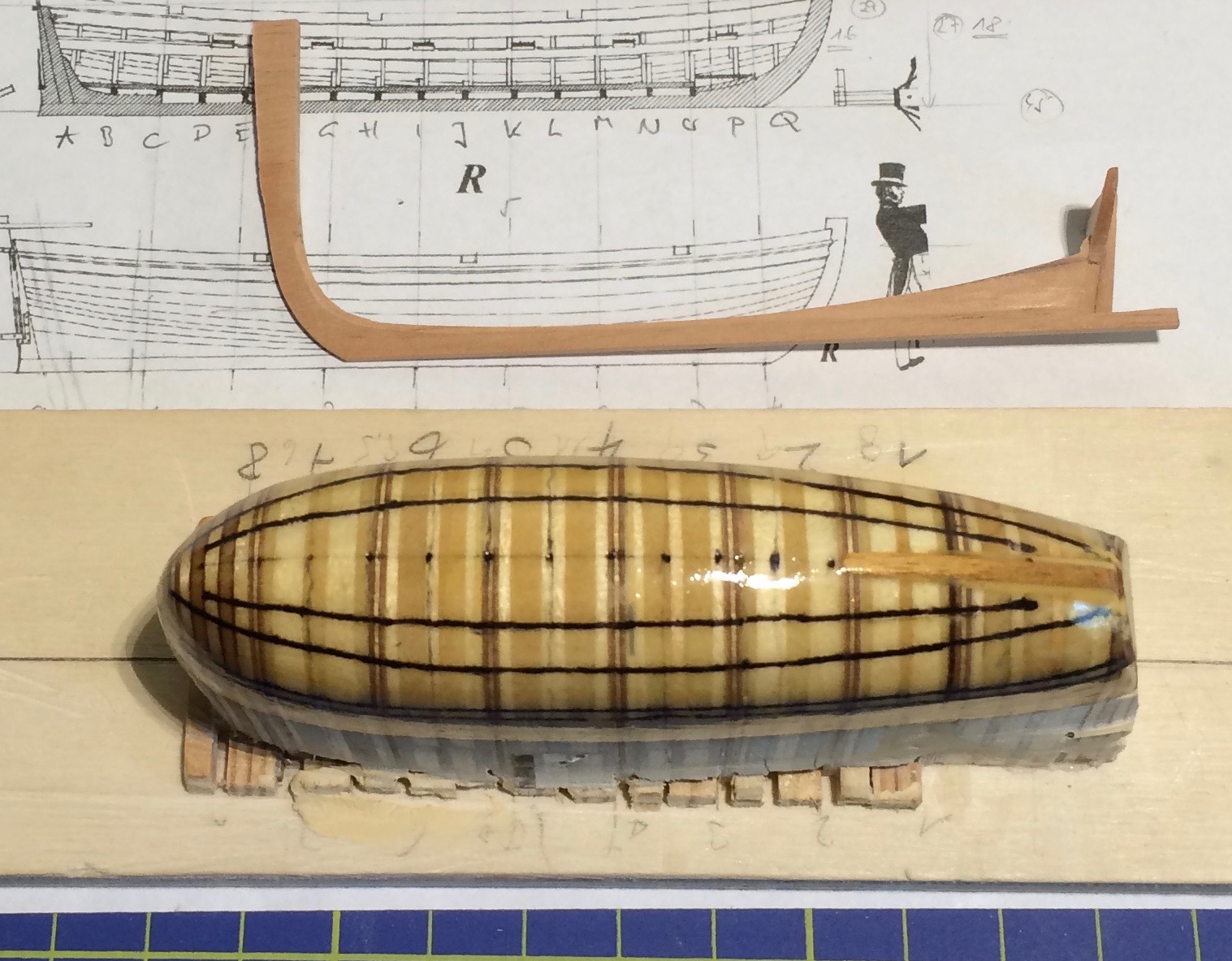
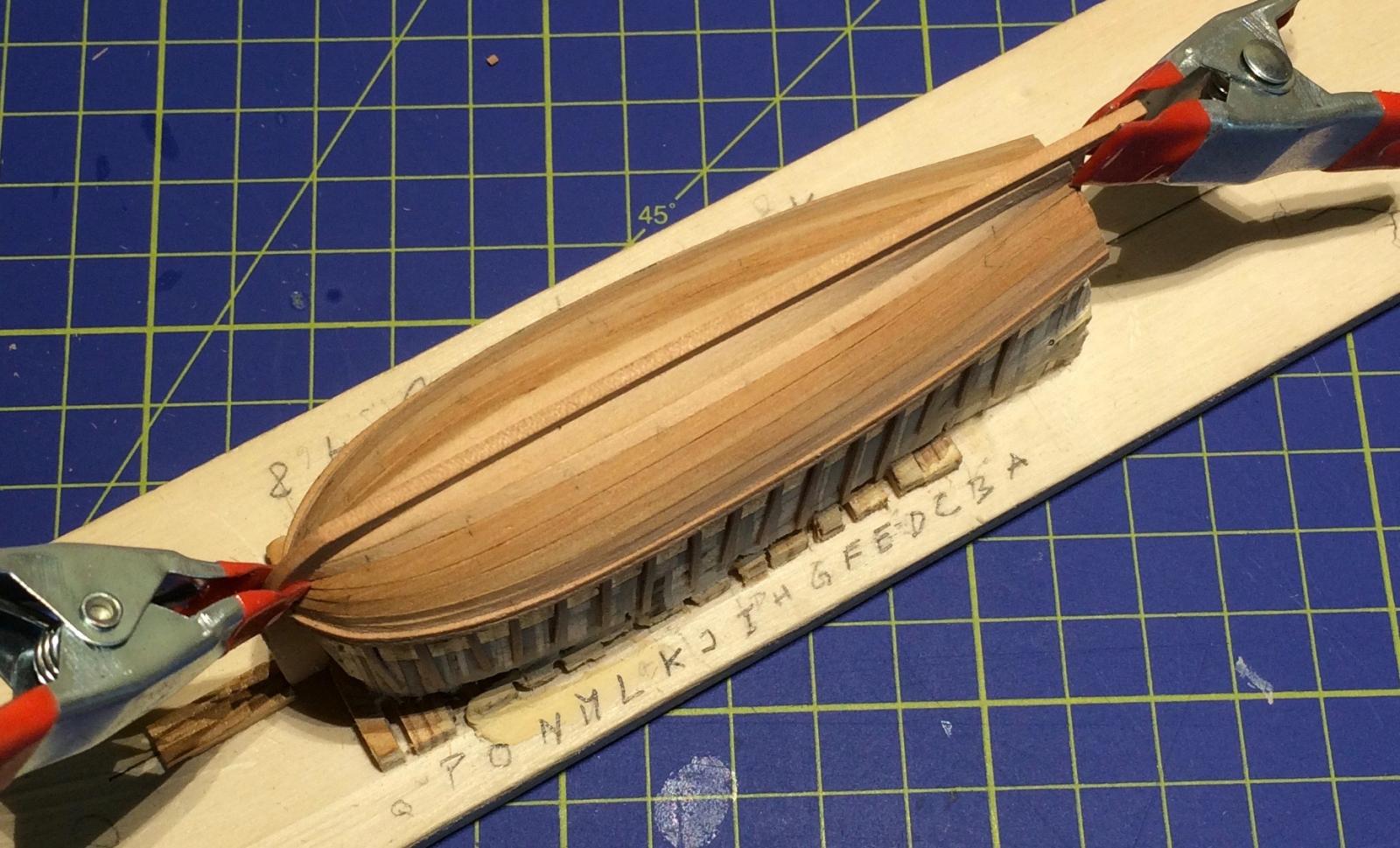
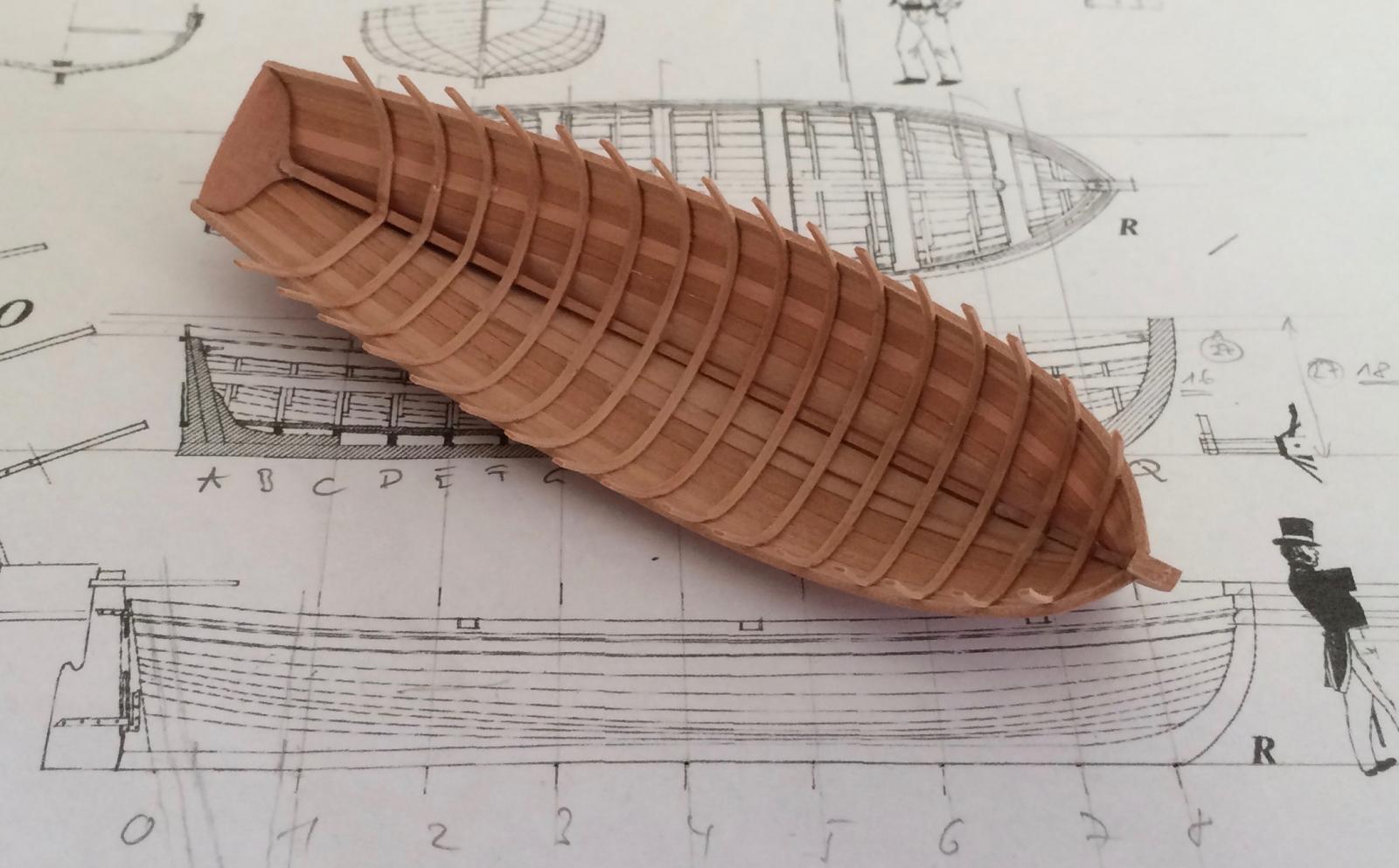
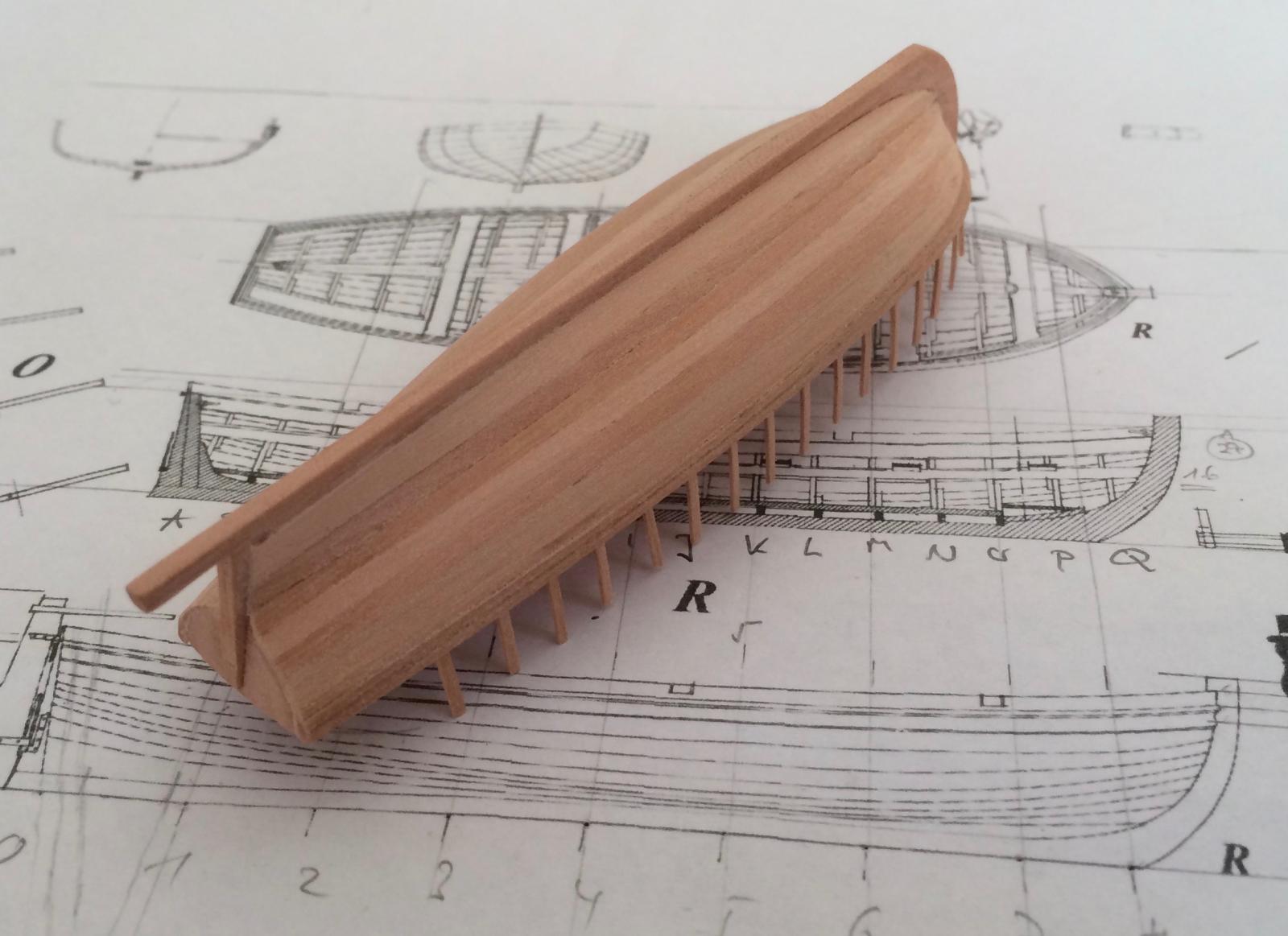
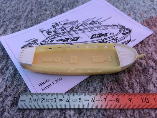
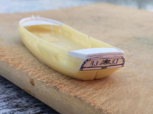
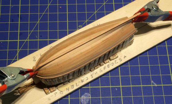
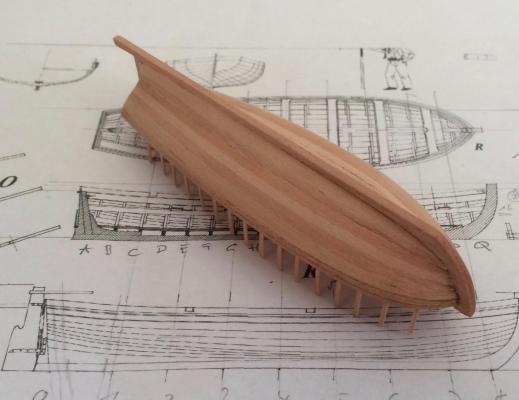
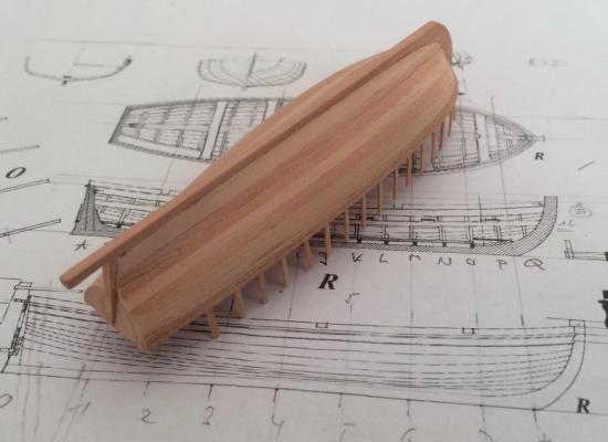
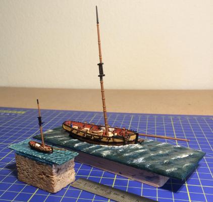
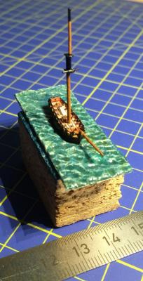
Too many things at the same time - here’s one of the culprits: Since I bought a second hand copy of Petrejus’ book I had to build an Irene (originally another Langton kit, a cruizer class brig). But that’s not the subject here. While waiting for the pear wood I had ordered I made a mold for a cutter )much the size of my Irene), then the wood arrived, and here is my first scratch built hull (I got much help from Tony’s log again). It’s 10 cm long and astonishingly light. Sadly, it would not swim. The hull will be painted black, though, so there is some room for cheating. The most important lesson I learned: Never force the wood and never trust the glue. I will bend the wood properly next time before glueing! Some small progress with the schooners was finally made. Two new false decks and other parts were drawn an cut, and now, after I finish the cutter, I can finally begin the planking. Cheers, Gregor


- 121 replies
-
- 13
-

-
- la jacinthe
- schooner
- (and 2 more)
-
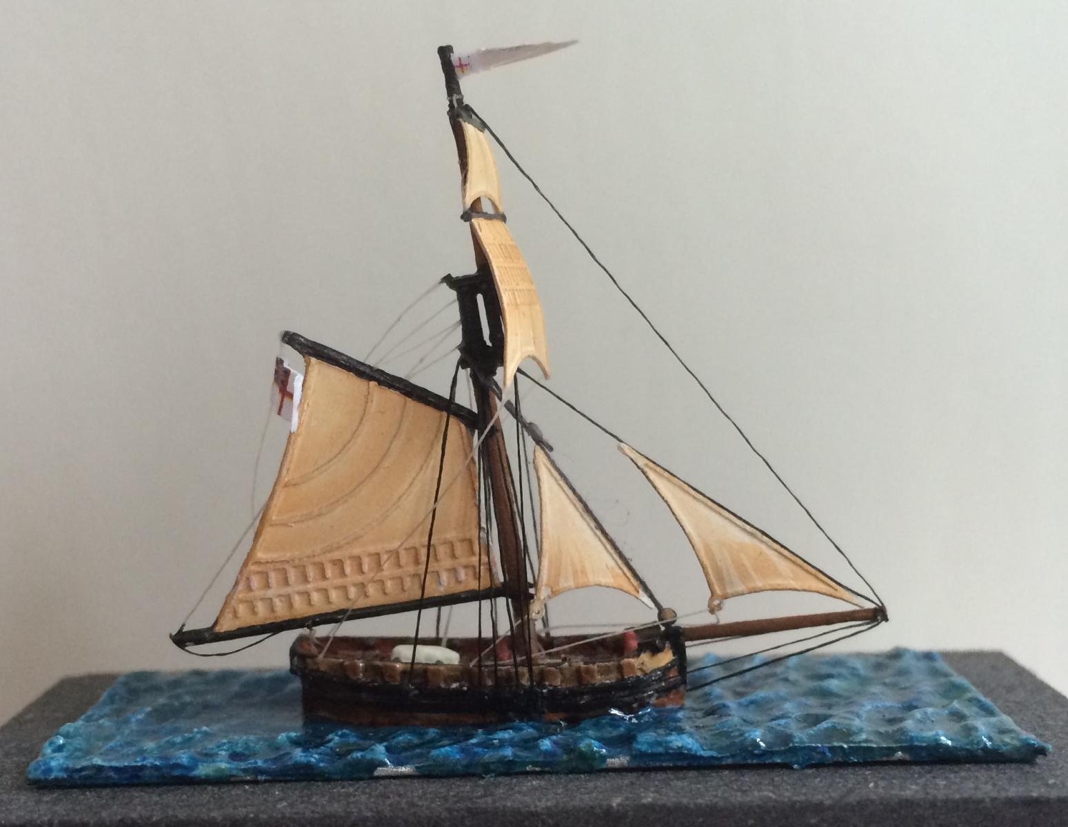
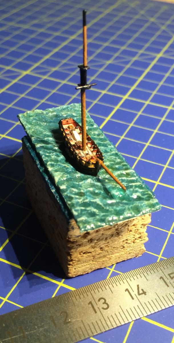
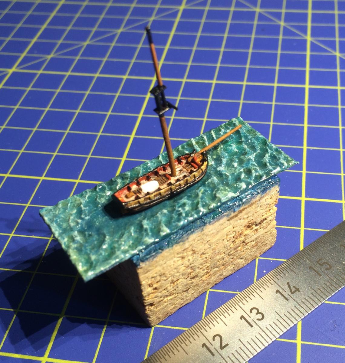
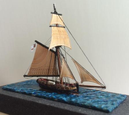
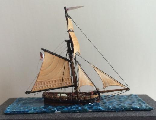
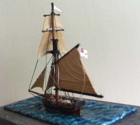
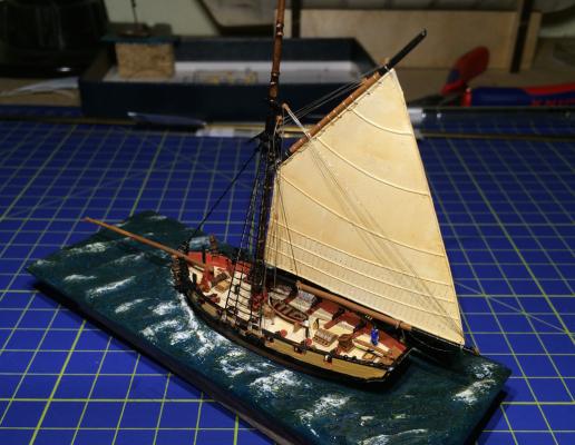
My fleet of cutters is now completely rigged; tiny Firefly is completed, Dragonfly still awaits her flags and crew. Here a few images: It was a good decision to replace mast and bowsprit with brass. They are looking slimmer, and are no longer prone to bend. This was the biggest challenge with Dragonfly, where I have used the original white metal parts. This will not happen again (yes, there is another project in the pipeline). The brass sails are relatively heavy, compared to the fly-fishing threads and soft masts. I tried to use copper wire (from a power cable), but this was totally out of scale. Now I’m quite happy with them. Cheers, Gregor
- 210 replies
-
- 4
-
-
- Sherbourne
- Cutter
- (and 5 more)
-
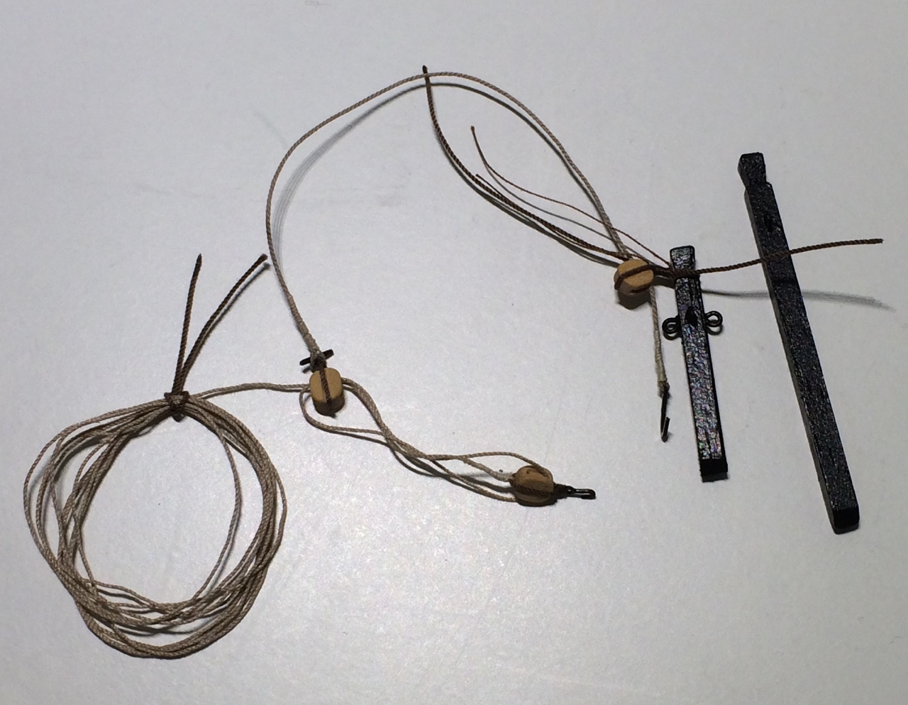
Rainy days – finally I’ve found time for my small cutters again. I spent hours with fly-fishing tread. As shown in the Langton’s manual, I drilled small holes (0.3mm) and glued a small, bent piece of wire in (you can see one of these hooks on the wale beneath the anchor; this one is for the bowsprit guys). The threads were fastened to that hook with CA, and a little brown paint simulates a block. Looks easy, doesn’t it? I’m feeling a little proud of myself. After many discarded, broken or otherwise destroyed pieces I came up with an idea for a three-hole-deadeye: A thin piece of 2mm brass tube was “filled” with a toothpick, glued, and drilled. I really can recommend a Langton kit as a rewarding side project! Cheers, Gregor
- 210 replies
-
- 4
-
-
- Sherbourne
- Cutter
- (and 5 more)
-
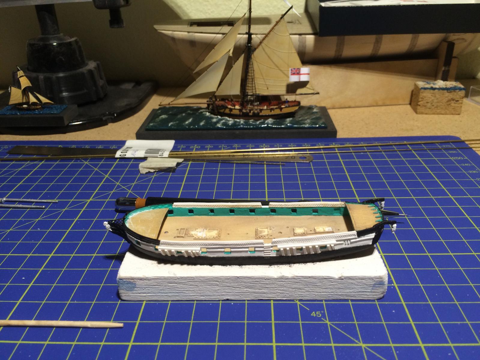
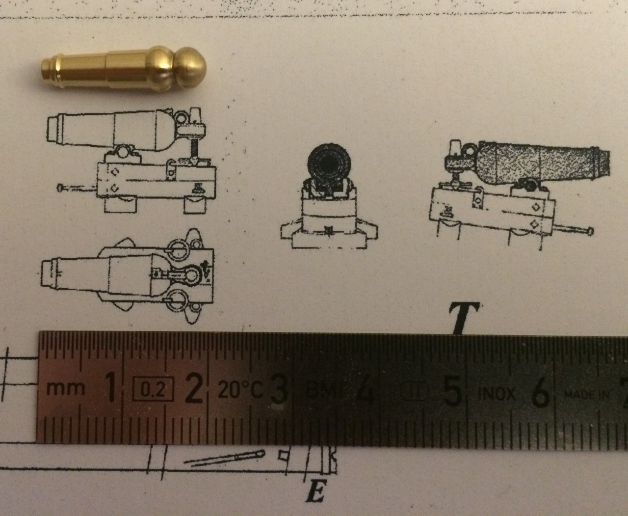
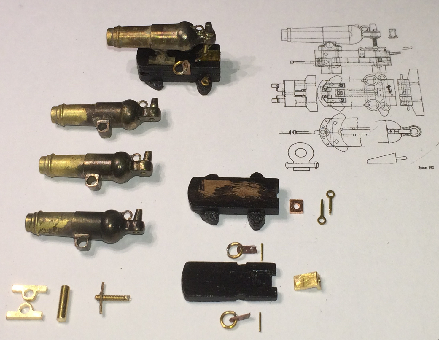
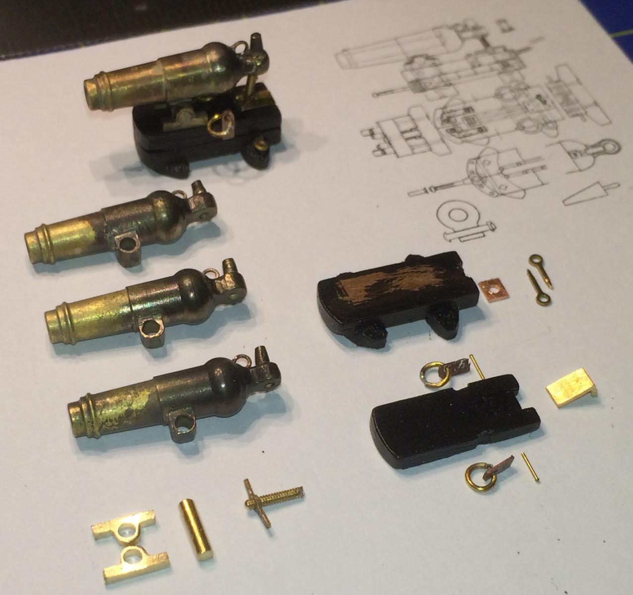
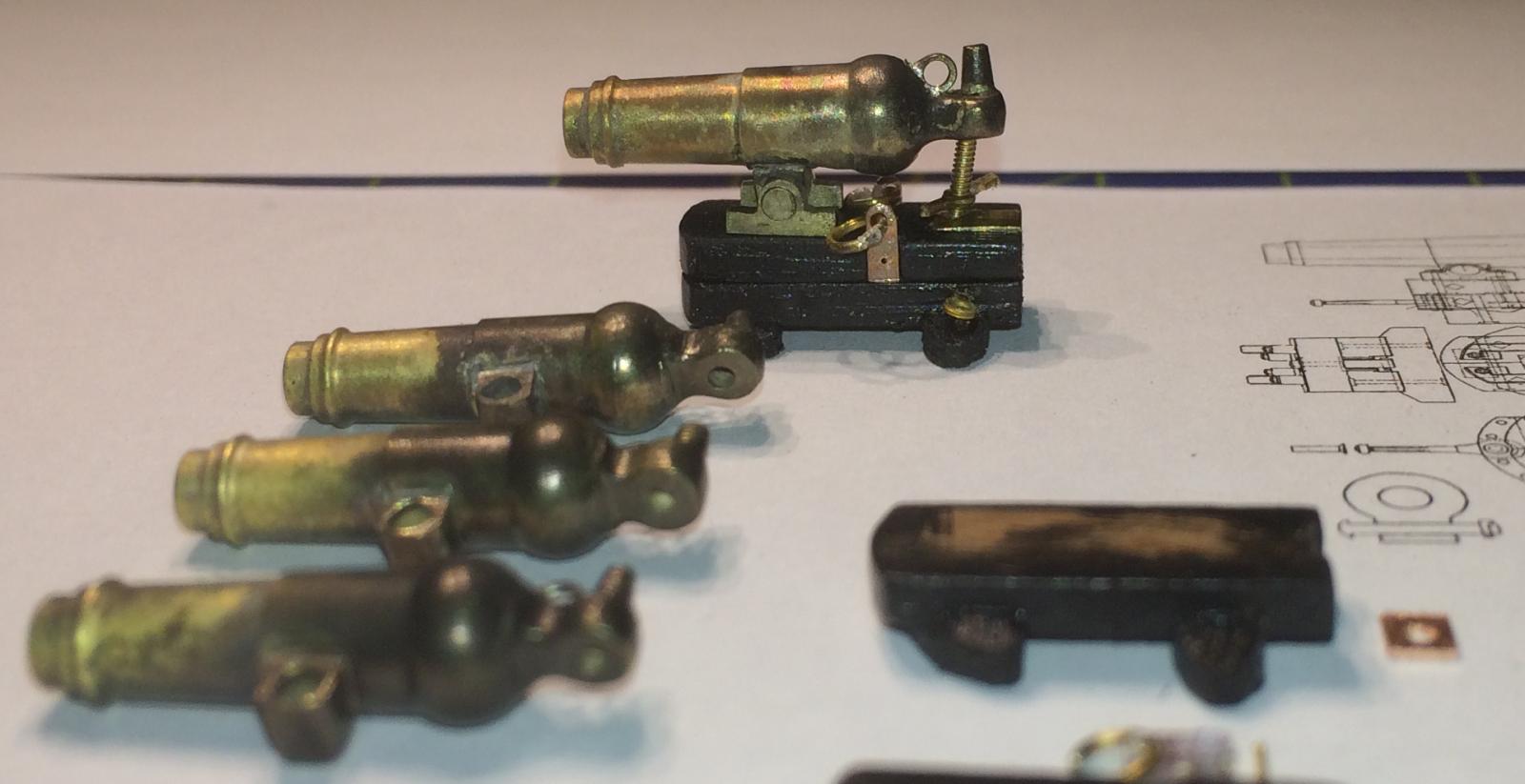
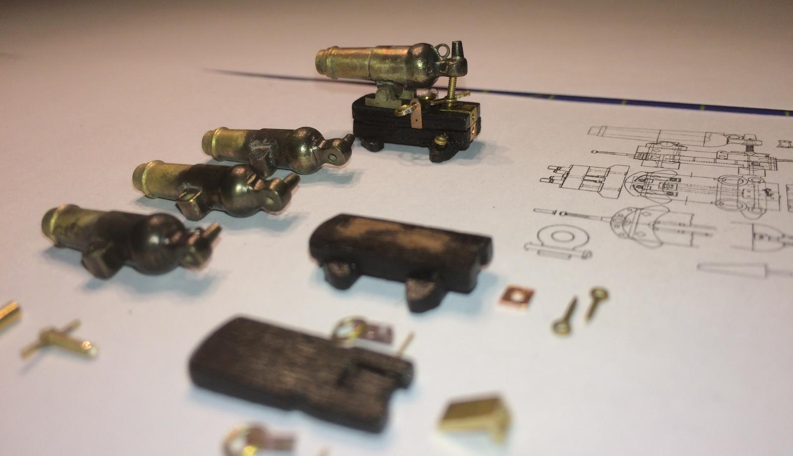
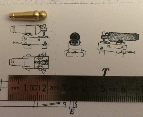
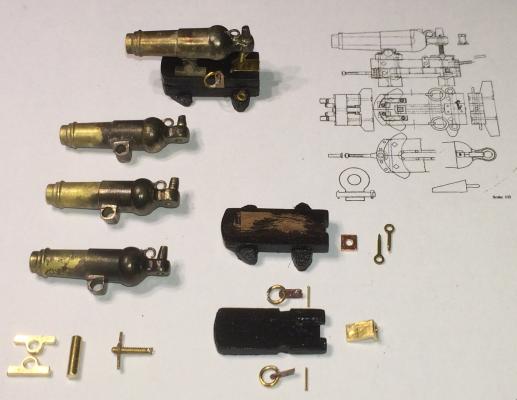
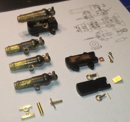
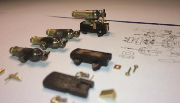
Finally, an update: While thinking about constriction details of both hulls (and their differences) and trying to get a better plan or copy for La Mutine I made most parts of the four carronades. A young man in training to become an airplane mechanic turned the brass barrels. They are 19 mm long, to give you a scale. The parts you see here are only loosely fitted, they will be blackened. The carriages are made from spare walnut and will be remade in pear (once I have the wood), only the ones for la Mutine will be painted black. Here the pictures, with greetings, Gregor

- 121 replies
-
- 12
-
-
- la jacinthe
- schooner
- (and 2 more)
-
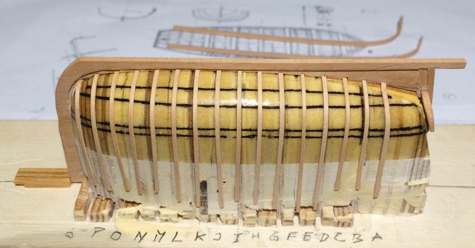
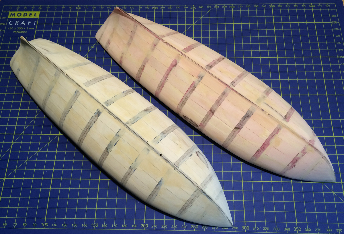
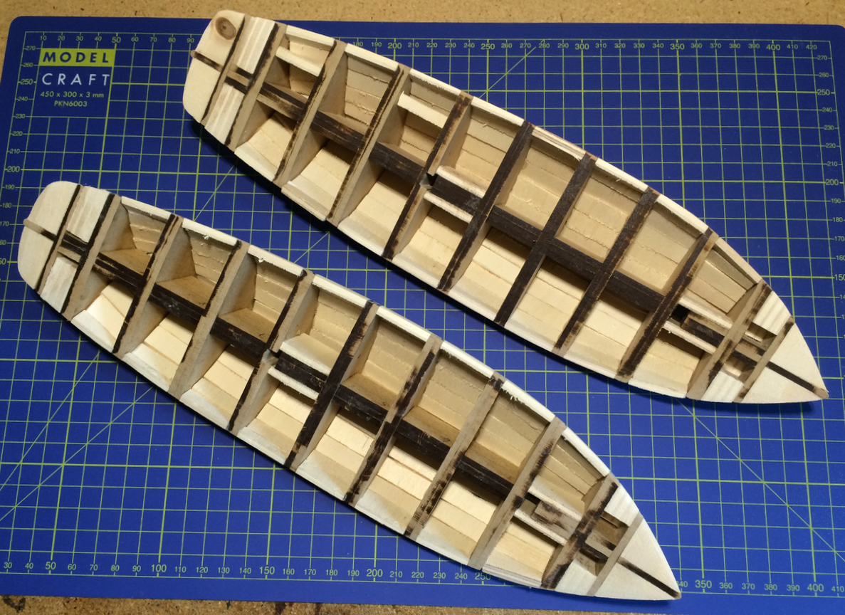
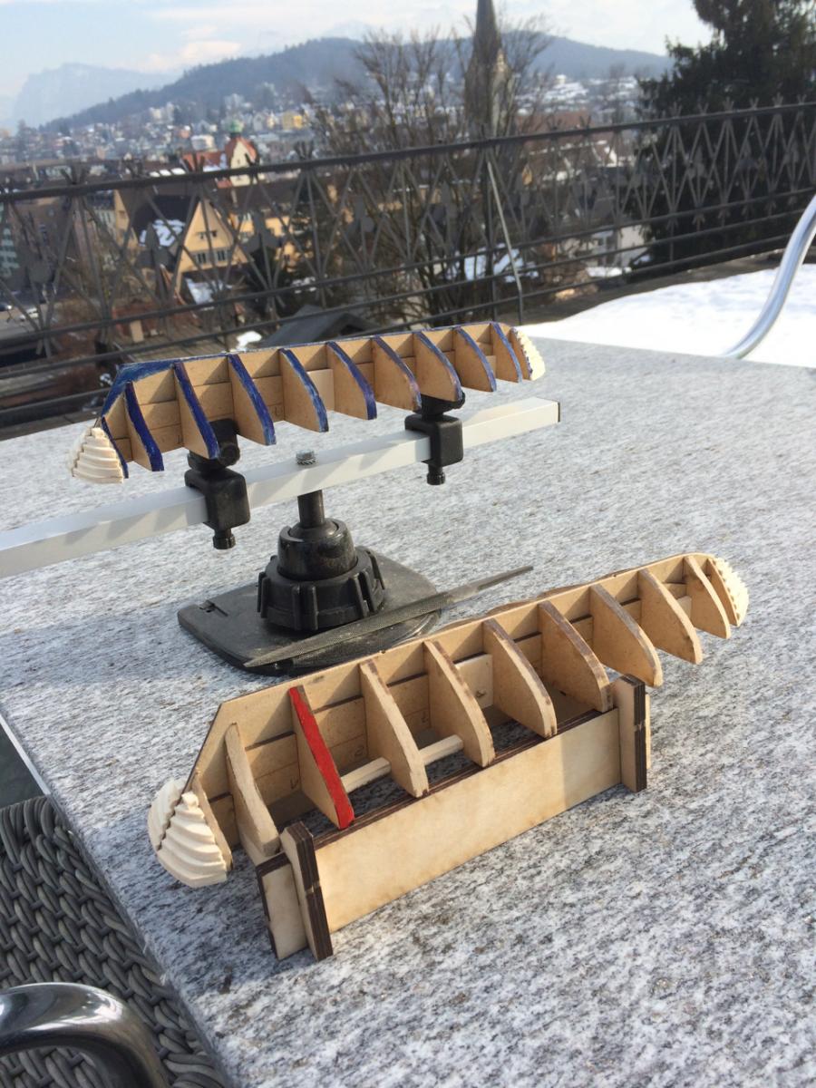
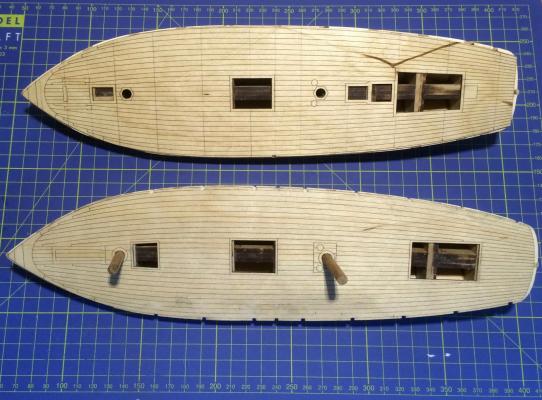
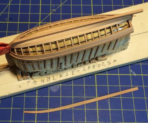
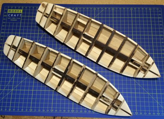
Shipbuilding time is rare at the moment, and I had to wait for a few dry days for much sanding outside. The space between the bulkheads were closed either with solid fillers (layers of plywood) or with little pieces. Here is the result: The two sisters are still looking identical - I call them "The Blue" and "The Red" hull. Now I can plan the next steps: The planking and the construction of the two versions of the bulwarks and transoms. Cheers Gregor

- 121 replies
-
- 14
-
-
- la jacinthe
- schooner
- (and 2 more)
-
Original Rigging for Cutters of 1763: with a Jib boom?
Gregor replied to Gregor's topic in Masting, rigging and sails
Phil, you can find historical details of the Sherbourne here: https://en.wikipedia.org/wiki/HMS_Sherborne_(1763). She was built in an special effort by the admirality to get as many small crafts as possible in a short time. The cutters of 1763 were built either in royal dockyards or by private contractors - hence the diversity of designs. It's really the detail of a "flying jib boom" listed in the original plan (but not shown in the drawing) that seems a bit strange. All the contemporary models I know of have a single bowsprit, but no jib boom. Gregor -
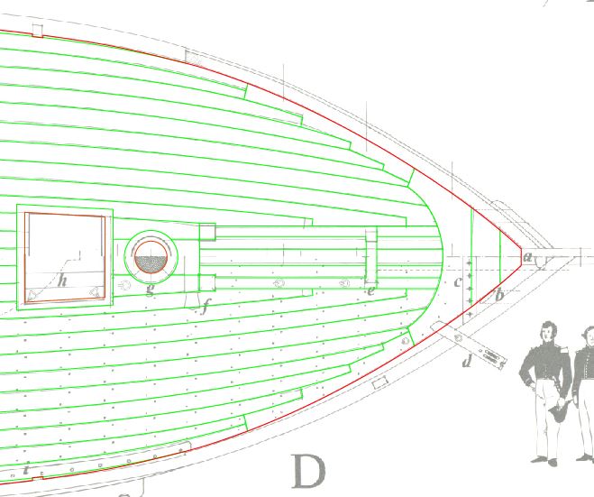
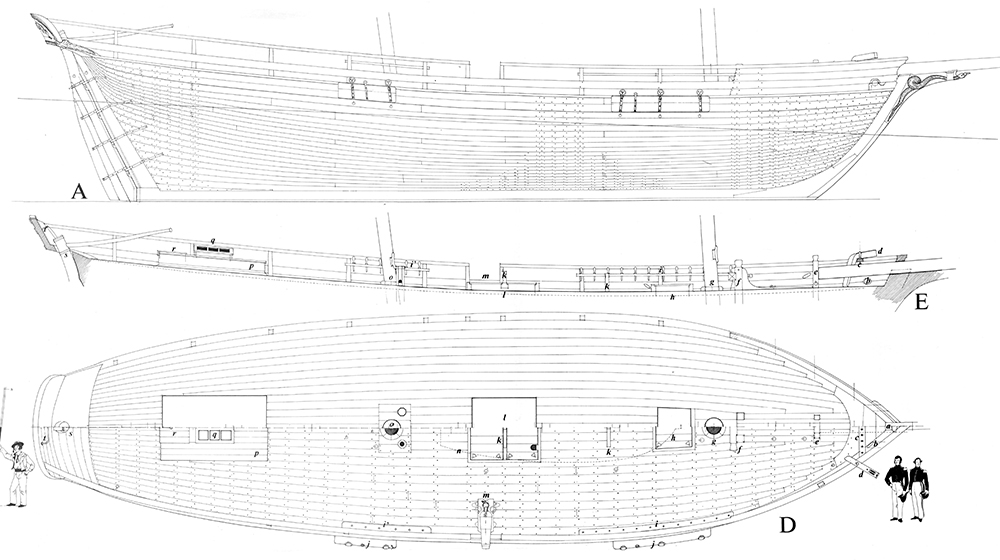
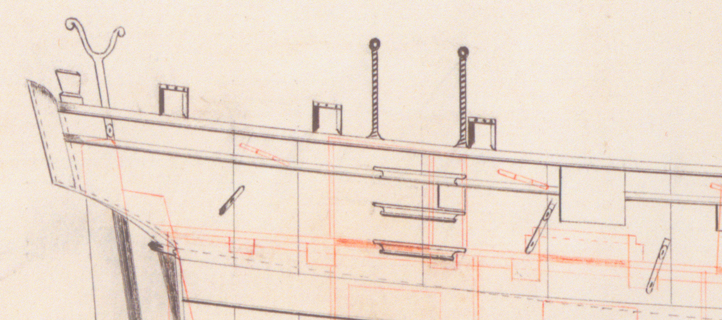
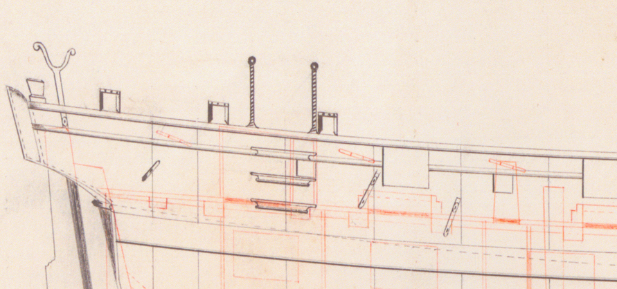
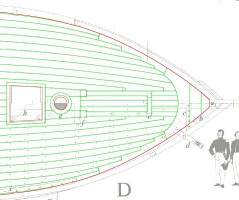
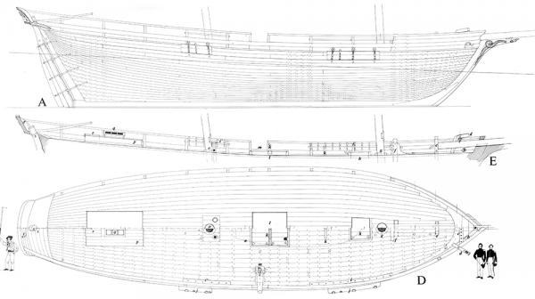
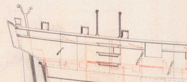
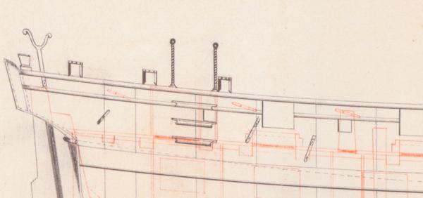
You're welcome, Tony. Boudriot has a clever way in his drawings; in a split image of the deck he can show its basic construction (very important: the position of the rail stanchions) on the port side, and the position of the deck furniture on the larboard side, including the nails etc. You can see that in the picture in my first post Gregor
-
Thank you for all the welcomes. It will be a slow project, so spectators will need something with more nutrition value than popcorn… @Michel: It's way too early to make definitive plans about the rigging and sails, but I'm sure "La Jacinthe" will get a complete set of mast and spars, standing rigging and most of the running rigging (as I did with the Sherbourne cutter). @Tony: Laser cutting is basically a form of printing (ever since we left the old matrix printers behind). You hit print in your vector graphics editor (Adobe Illustrator in my case), choose the laser cutter instead of a printer in the usual dialog window, and set the parameters, like you would do with printer options. In my case, the laser cutter had to cut red paths (RGB 255/0/0) and engrave green paths (RGB 0/255/0), set in 0.001pt. In another options dialog, you have to choose the parameters for energy, frequency and speed, depending on the material you are trying to cut (I was very glad to see that there were pre-sets for MDF and plywood). In this manual (https://www.epiloglaser.com/downloads/pdf/fusion-web-10.30.13.pdf) for a laser cutter of the type I used you will find more information than you ever wanted to know… Cheers, Gregor
- 121 replies
-
- 4
-
-
- la jacinthe
- schooner
- (and 2 more)
-
Fun days in my wharf: HMC Firefly is ready for rigging, as is her big sister, the Dragonfly. Turning to things less complex, here at last is the new pennant for the Sherbourne. All this is a pretext to tell you that I have opened a new build log for my next project – you can catch a glimpse of the French schooner “La Jacinthe” in the background, or head over to http://modelshipworld.com/index.php/topic/9743-french-schooner-la-jacinthe-la-mutine-by-gregor-–-164-scale-1823-1835/?p=288578 . All the best, Gregor


- 210 replies
-
- 6
-
-
- Sherbourne
- Cutter
- (and 5 more)
-
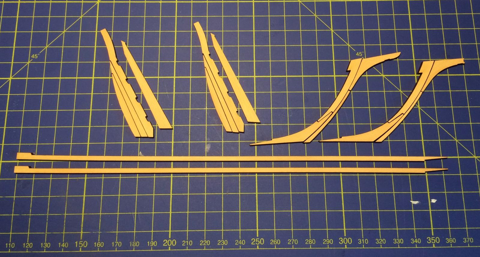
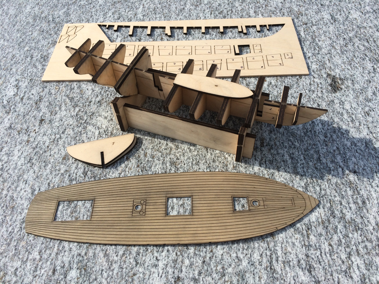
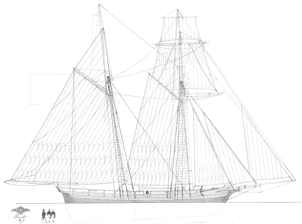
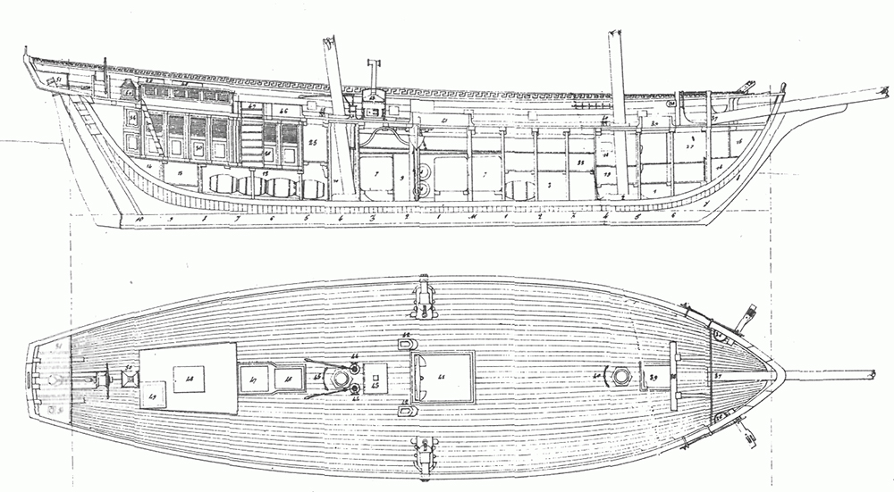
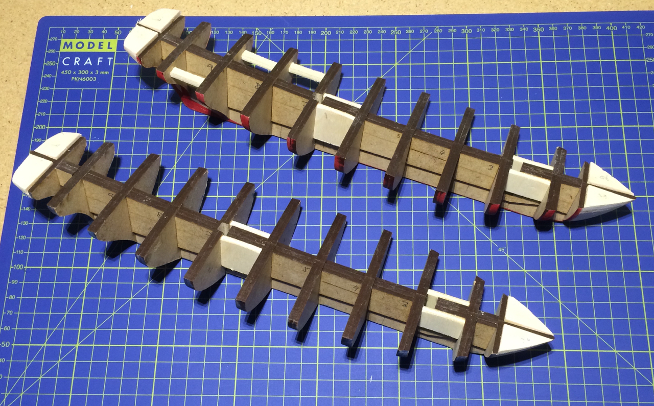
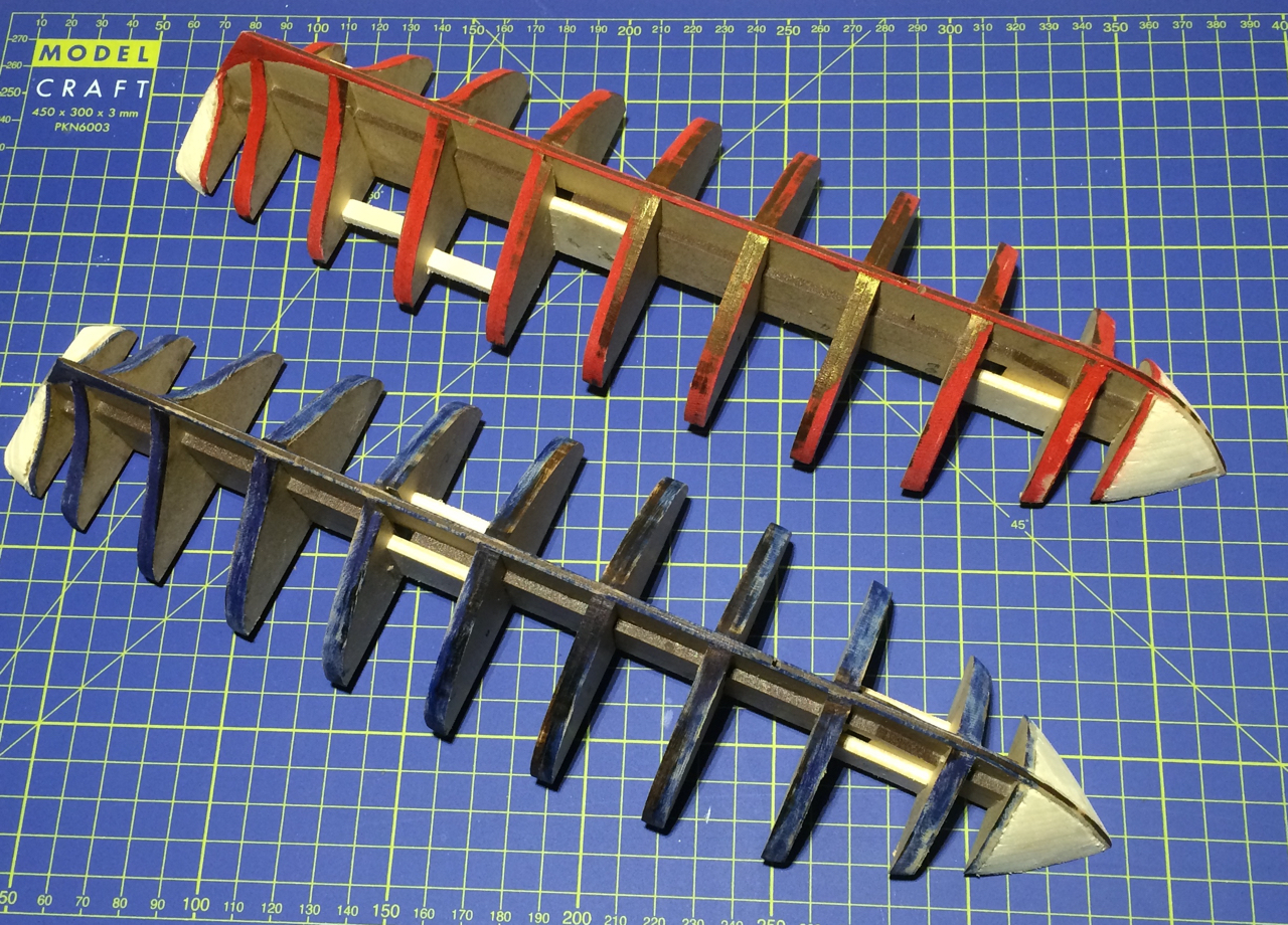
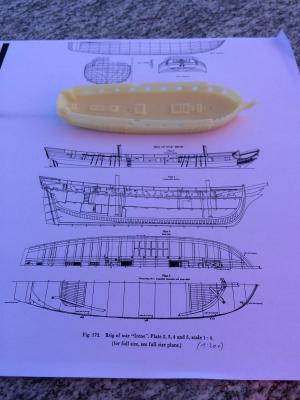
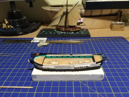
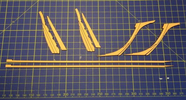
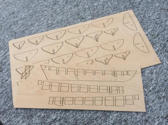
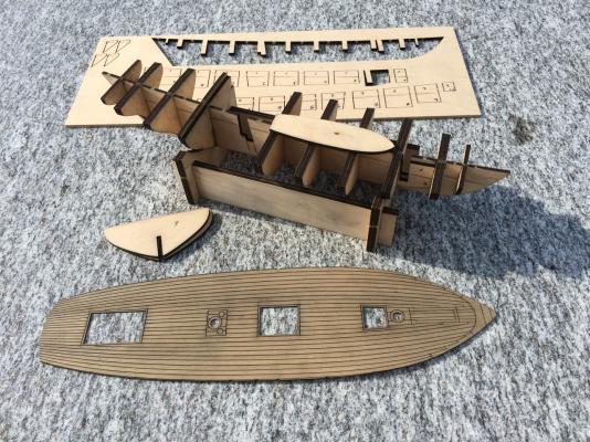
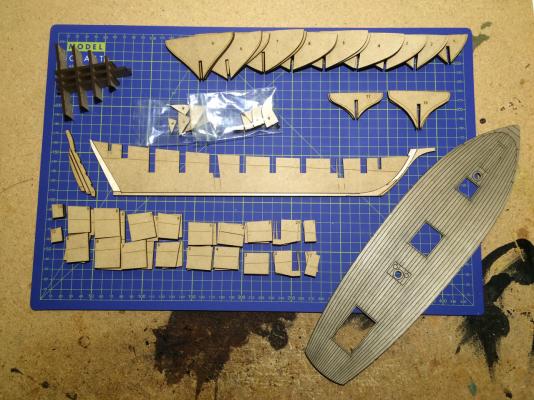
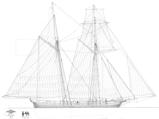
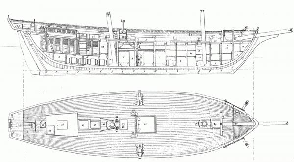
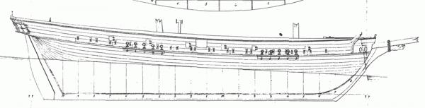
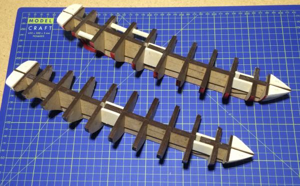
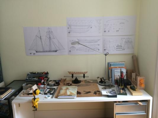
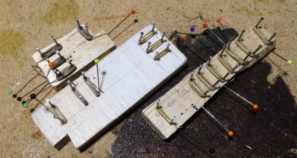
It was in summer 2014 when I had the idea to build the French light Schooner “La Jacinthe” after the plans of Jean Boudriot. Together with five sisters she was launched in 1823, and in the following year five more ships were built, among them “La Mutine” (“The Rebel”). As my cutter HMC Sherbourne she should be in 1:64 scale, so I scanned the plans and traced bulkheads and false keel in a way so I could build everything with plywood of 3mm. For that I used Adobe Illustrator, so I could laser cut the pieces in the FabLab of the local technical university. “Printed out” in late summer, you can see here the bulkheads, false keel and deck, a few small parts and a piece for a jig that will help me to build a cutter. When I wanted to start building, alas, I saw that the false keel was totally warped. So I had to go to the university again, and cut everything again, but this time in MDF. And while I was at it, I did everything twice. Just for testing purpose I cut keel, stem etc., I will user these parts as templates when working with pear wood. In the upper left corner you can see a jig that will act as a bulkhead former. But why do everything twice? I simply couldn’t decide: build the “Jacinthe” or the “Mutine”? The latter is shown in Boudriot’s book, after a refit in 1835. The main differences are closed and elevated bulkheads, new deck layout, iron pumps and anchor chains, a steering wheel, new chains and a new bowsprit, set in a different angle – in general, the “Mutine” appears much more seaworthy than the very lightly built “Jacinthe”. So the plan is to build both: a fully rigged “Jacinthe” in natural pear wood, and a hull model of a black-painted, coppered “Mutine”. The twin build should not be boring or repetitive. Well, have to build two identical hulls, but all the other details mentioned promise to be sufficiently different from each other to make this a very interesting project. Here a look of the two schooners, “La Jacinthe” (1823) ans “La Mutine” (1835): The foundation is already laid: the two sisters can hardly be told apart yet. This will be a slow build, and quite an adventure; my only experience in building wooden models is the Sherbourne kit, which I modified to my liking and where I learned the pleasure of working from scratch. And as I have to do the heavy sanding outside, progress is dependent of the weather (yes, the with stuff is snow, for those having the privilege of living in a moderate climate). Cheers, Gregor


- 121 replies
-
- 19
-
-
- la jacinthe
- schooner
- (and 2 more)
-
Thank you, my friends, for the likes and kind comments – the compliments go both ways: Don’t underestimate your collective influence! I’m glad I don’t have to close this log too quickly: Kester has it right; there is a new pennant to add (I will give her a tricolour pennant to match my own streak of independence); and while I ordered a few small things for my next project I added a additional kedge anchor for the Sherbourne, to be placed in the starboard chains. And, this afternoon, two handspikes for the windlass... There are still her two little sisters, the Dragonfly (1:350) and Firefly (1:1200) to finish, too. This is quite convenient, because I have to do the heavy sanding outside – it’s too cold for that at the moment. In spring, everything will be ready for the Schooner La Jacinthe after the plans by Jean Boudriot in 1:64. The false keel, deck and the bulkheads are already cut. But for now, the cutter story is not over, yet. All the best, Gregor
- 210 replies
-
- 7
-
-
- Sherbourne
- Cutter
- (and 5 more)
-
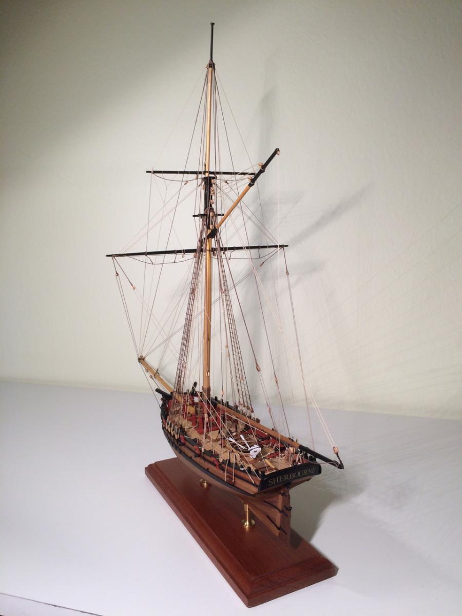
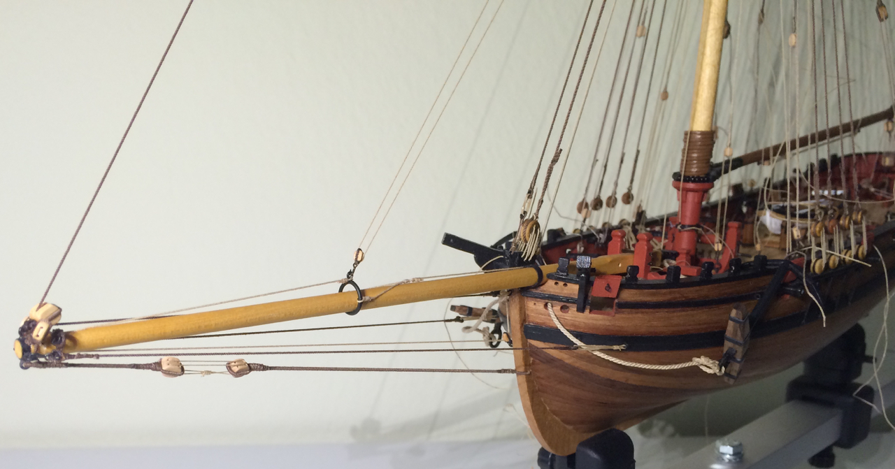
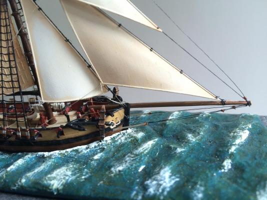
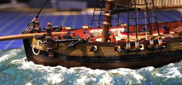
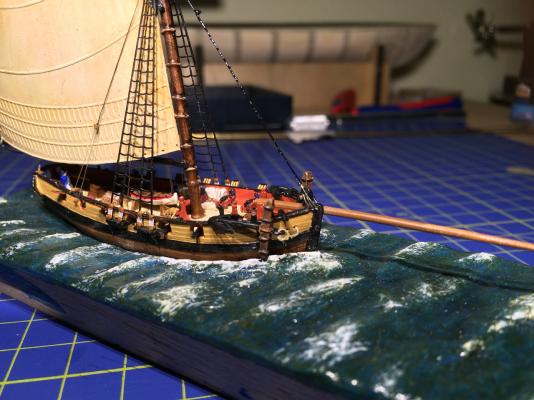
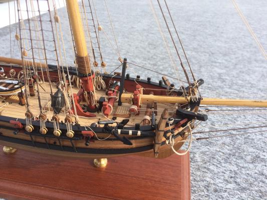
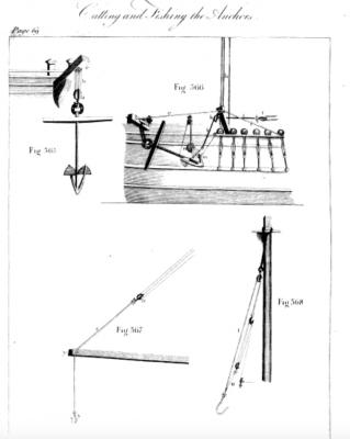
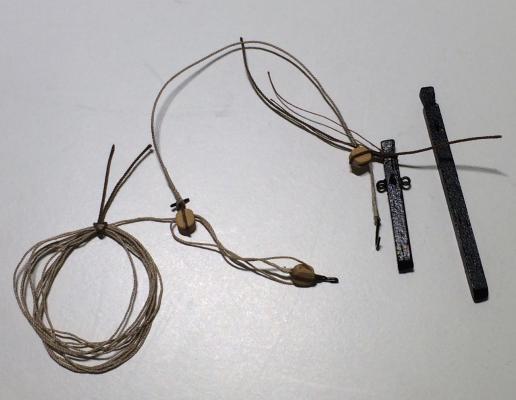
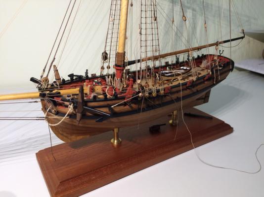
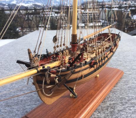
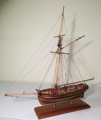
I always wanted to know how an anchor comes to rest at the rail of a cutter. Discussions and Literature are mainly about bigger ships. In smaller vessels anything seems possible. The best descriptions I found were in Harland an Lever (from page 68, http://books.google.ch/books?id=HmJJAAAAYAAJ&printsec=frontcover&hl=de&source=gbs_ge_summary_r&cad=0#v=onepage&q&f=false). So I had to make a fish-davit. I liked the one on the Victory the most (the Sherbourne and her bigger sister share the builder, after all). Several models had to be tested. The first, only as long as a man, and standing in the chains, did obviously not work (see the angle of the white fish lanyard). Double length was much better. A strong line goes from the cathead to the davit on to the chains to keep everything in place. The davit itself hangs at the burton tackle an can within limits be lifted or lowered, as it is standing in an iron made fast on deck. Maybe the davit should be a trifle longer? But I really was able to fish the anchor and place it at a timberhead, with a little help of my boathook-fingers. The little wooden fender (or shoe as it is called by Lever) wasn’t really helpful protecting the model hull, but makes a nice detail. I fear this is the last detail to add to my Sherbourne. She got her flags, too. Cheers, Gregor

- 210 replies
-
- 11
-
-
- Sherbourne
- Cutter
- (and 5 more)
-
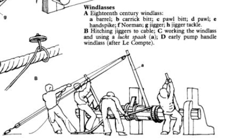
I think, to get the cable up, it should go over the windlass: Then the crew can turn the windlass by pulling the hand spikes down with their own weight. If the cable went unter the windlass, they would have to lift the hand spikes to get the cable up. Sitting in my office, I have to wait till evening to consult a picture showing a working windlass (tested with a pen and a cable for my iPhone). Gregor Here the picture, from Harland: Seamanship in the Age of Sail, p. 263
- 269 replies
-
- 2
-
-
- Caldercraft
- First build
- (and 3 more)
-
Beautifully done, Tony. I especially admire your effort to make everything by yourself, and doing such a good job with that. I'd need a new dictionary to express my admiration properly. And thanks for showing and explaining every step and experience so generously. Reading your posts, one question arose (it might be a problem of perspective in your pictures): Does the belaying rack at the bow interfere with the free running of the anchor cable? - I imagine the cable will be streched between windlass and hawse hole at certain times. I think the cable goes (in two turns, or even three) over the windlass, so there might be a problem. It was fun to read your postings almost in real time, with constantly another, new one popping up, showing more wonders to stare at! All the best, Gregor
-
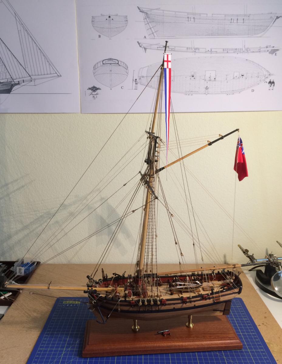
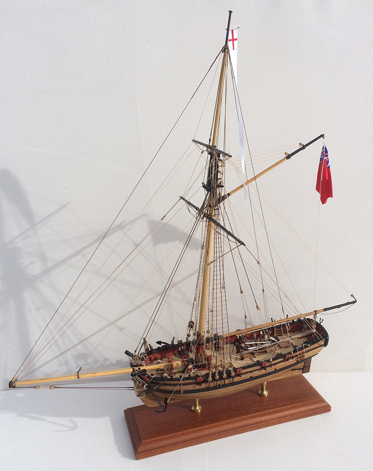
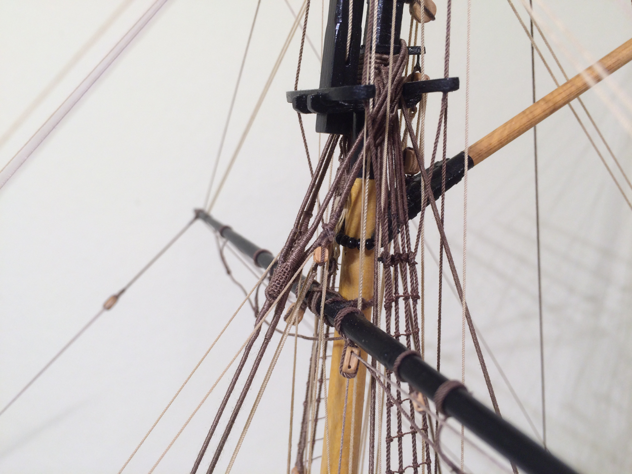
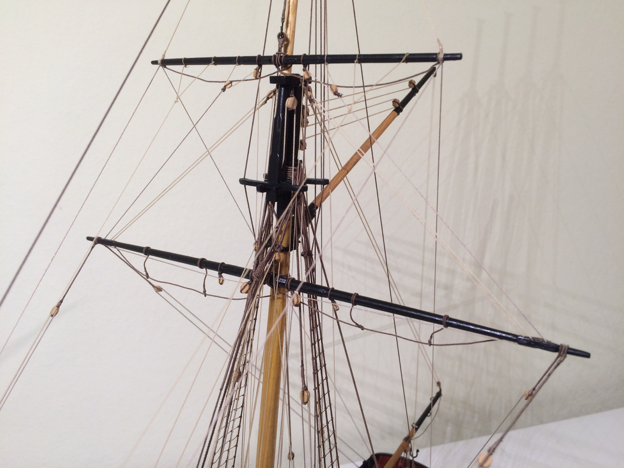
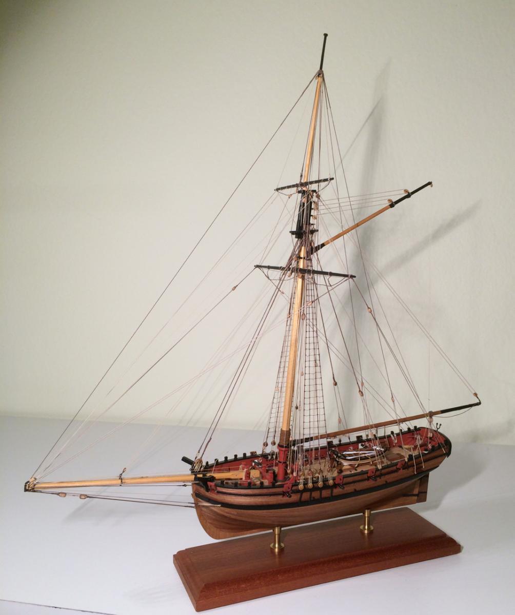
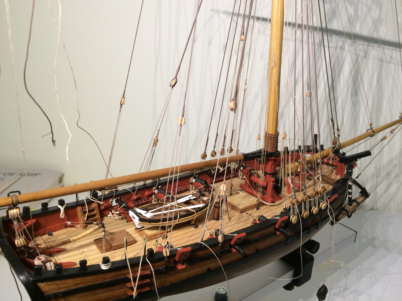
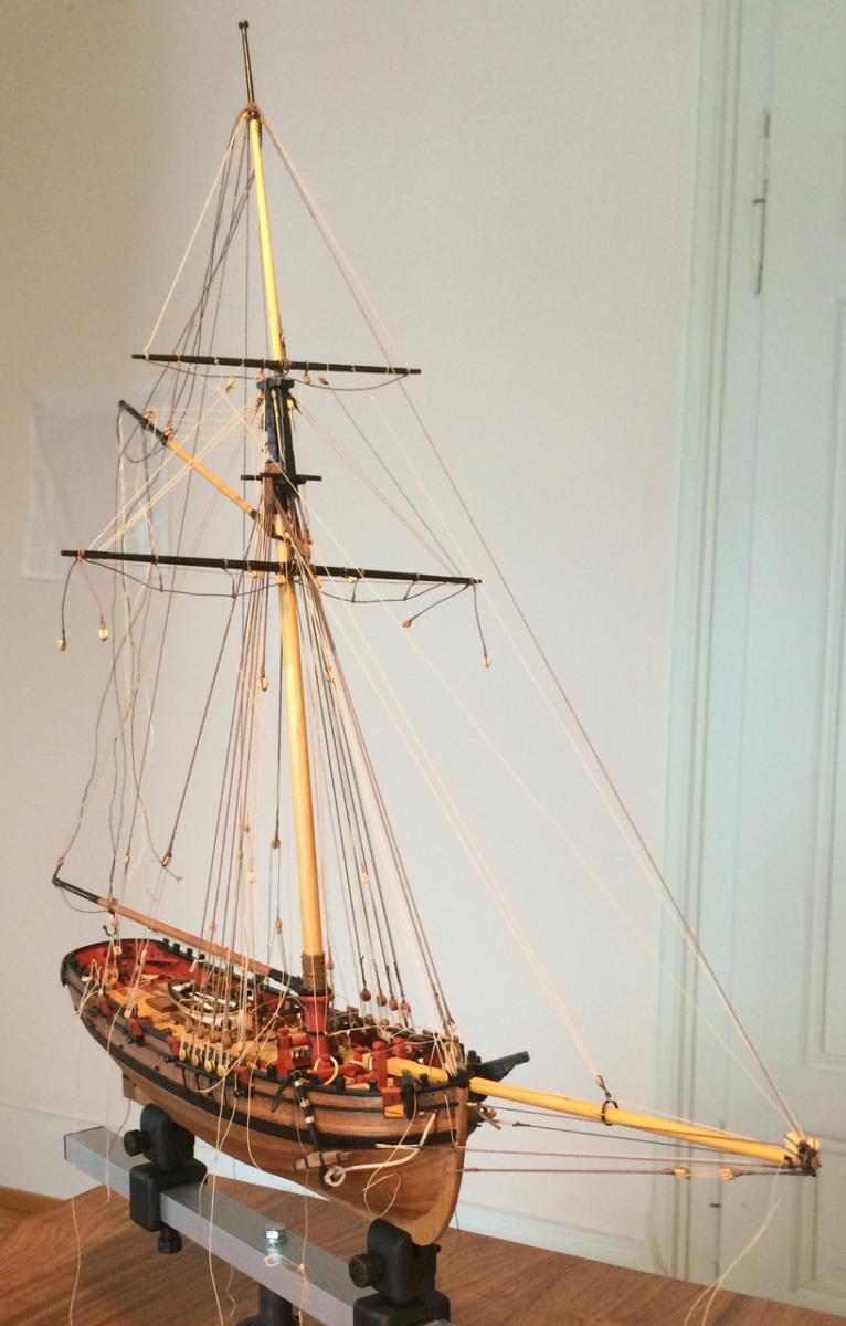
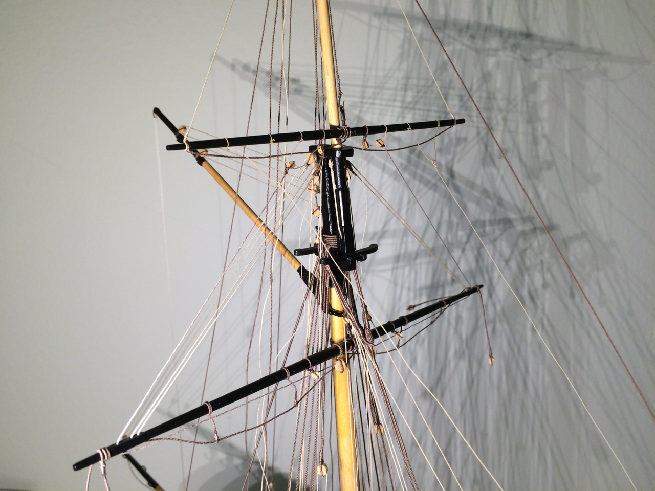
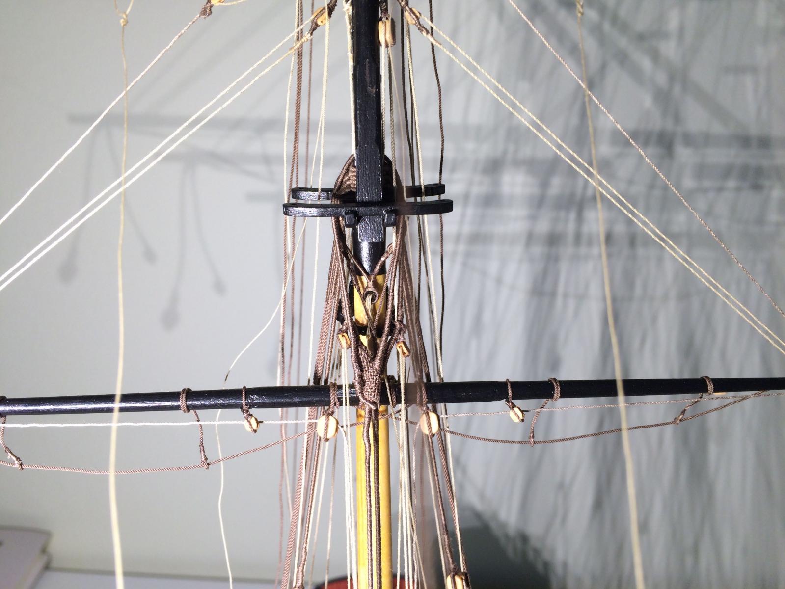
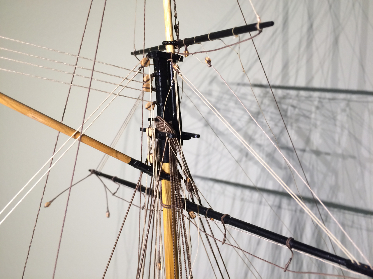
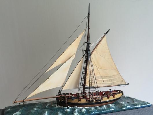
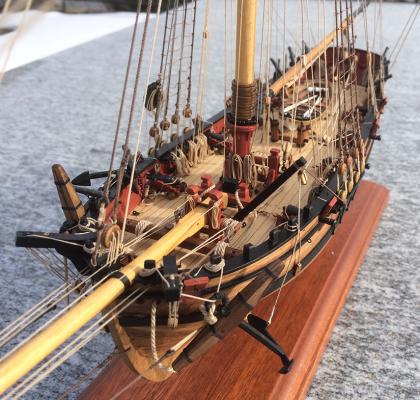
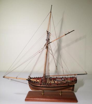
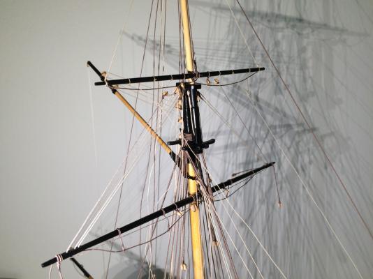
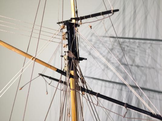
I have been busy since Christmas. Today I found Tony’s question about topmast shrouds (http://modelshipworld.com/index.php/topic/8622-topmast-shrouds-for-sherbourne/?p=279366) - here is my solution: As described by Wolfram zu Mondfels they go around a futtock stave (8mm long brass wire of 0.5mm) and are made fast to the shrouds by lashings. It’s one of several possible solutions. As I made crosstrees and not a spreader, they could also have gone down parallel to the main shrouds to be belayed at the deadeyes. I preferred the shorter version. Then came the ratlines; there is not much to say (except: don’t do them all in one stretch of eight hours if you’re no longer a teenager, as your back and every muscle there will severely complain.) Now the yards are squared, every rope and line is securely belayed, it was like a balancing act. Here some impressions. Now I’m coiling the ropes. Cheers, Gregor


- 210 replies
-
- 7
-
-
- Sherbourne
- Cutter
- (and 5 more)
-
Tony, it seems I have missed all your questions outside your log. But here is another solution for the topmast shrouds; beautifully executed by Jean Boudriot on his cutter Le Cerf (http://modelisme.arsenal.free.fr/artdumodelisme/Le%20Cerf/index.html). This method is also shown by Wolfram zu Mondfeld, I made it just like that in my Sherbourne. Gregor
-
Kurt, I wish you every success with your project (I hope you share it with us in a build log). I only hope you consider the implications of what you are trying to do. Simply elevating the level of the deck so that the guns fit the new portholes is the easiest part. Outboard, it changes the positions of the chains and the wales; in the stern (also simplified in the kit) it would mean structural changes. But I understand the urge to change things all too well, and learned a lot in doing so. Gregor
- 210 replies
-
- 1
-
-
- Sherbourne
- Cutter
- (and 5 more)
-
Hi Kurt There was nothing technically wrong with the bulwark pieces in the kit. I would recommend soaking and bending them around a tea mug before gluing. Just make sure not to confuse the two sides. In my model the sweep ports are a little too small – my fault. I made another mistake: I should have made sure that the distance between the ports and the upper end of the bulwarks is the same everywhere; a little careful sanding will do. You can do that with the bulwarks mounted, before adding the capping rail. My only “complaint” regarding the bulwarks was that they are not entirely true to the original plans: The portholes are sitting too low. To correct that, it would mean to elevate the deck accordingly – I wouldn’t recommend opening that box. I think these bulwark patterns are an excellent idea to make a beginners kit even easier to build. Good luck, Gregor
-
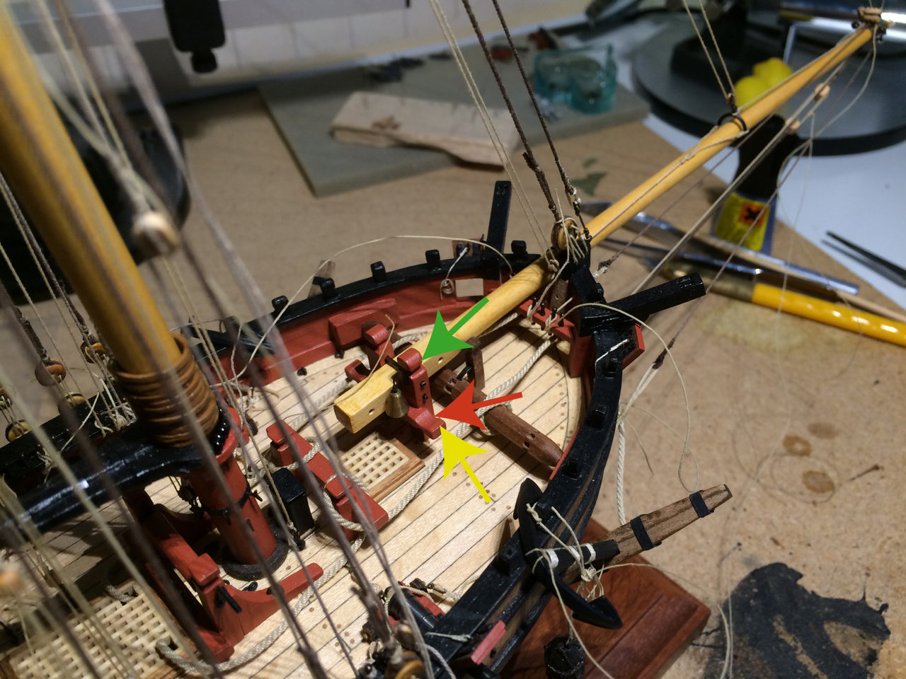
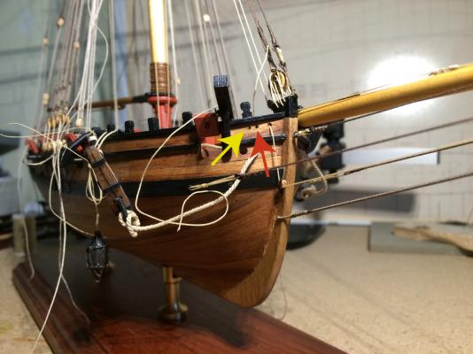
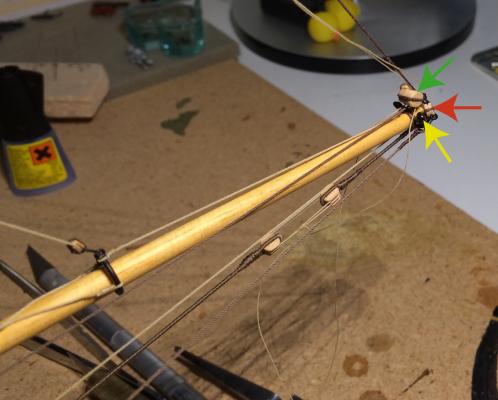
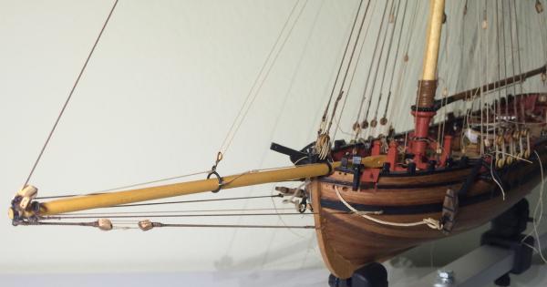
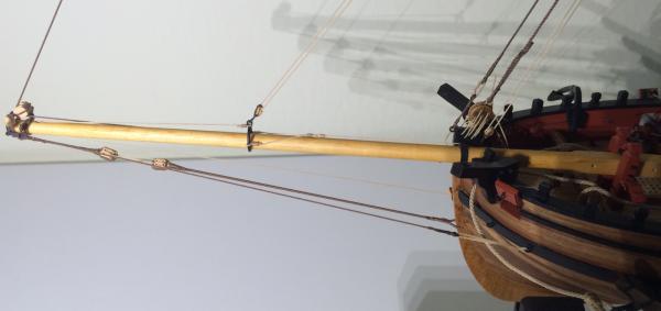
Tony, welcome to my personal dark side… At first, I wanted to use the timberheads extensively, but that did’t please my eyes. At the moment I’m thinking of doing the following: Inhauler and outhauler are belayed in pin 1 and 3; the inhauler comes in on the port side of the stem, and the outhauler through a hole I made in the bulwark (I didn’t like the idea of lines coming in over the railing). The bowlines rove through the triple block on the cranse iron, come in over the railing and are belayed at the tip of the bowsprit bitt (green arrow). The squaresail yard counter-brace starts on a block at the cranse iron (standing end), roves through the block at the end of the pendant, comes back through the block, comes in through a hole in the bulwark, and is belayed at the bowsprit bitt crosspiece (red arrow). The topsail counter-brace (the topsail braces are belayed at the aftermost pins in the stern) starts at the yard, roves through the thimble just behind the cranse iron, comes in through a hole in the bulwark, and is belayed also at the bowsprit bitt crosspiece, outside the squaresail yard counter-brace (green arrow). This is far from perfect; the topsail counter-brace will chafe at the cathead, both will be made fast with a clove hitch instead of a more suitable pin. Starting again from scratch, I would make a bowsprit bitt with pins (and knees!) I hope this helps answering your question. I add my belaying plan here; but now that Chuck’s Cheerful plans are out, I think they are a solid base give the Sherbourne a modern rigging. In hindsight, though, I think also that a historically correct rigging would be very interesting (although I still cannot make sense of the flying jib boom on the bowsprit). I’m looking forward to see your new windlass, Gregor Sherbourne Rigging.pdf

- 210 replies
-
- 2
-
-
- Sherbourne
- Cutter
- (and 5 more)
-
Hi Kurt This is the one I have bought: http://prints.rmg.co.uk/art/494933/plan-of-the-sherborne-1763. I thought it the cleanest version, and like it very much, standing framed on my worktable. I don't think any of the others give more details. Title: Plan of the 'Sherborne' (1763) Product code: J8467 Copyright: © National Maritime Museum, Greenwich, London Cheers, Gregor PS: I hope you will show us your Sherbourne in your own build log - enjoy it!
-
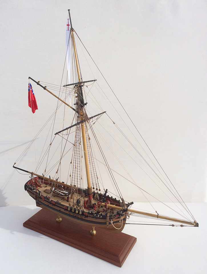
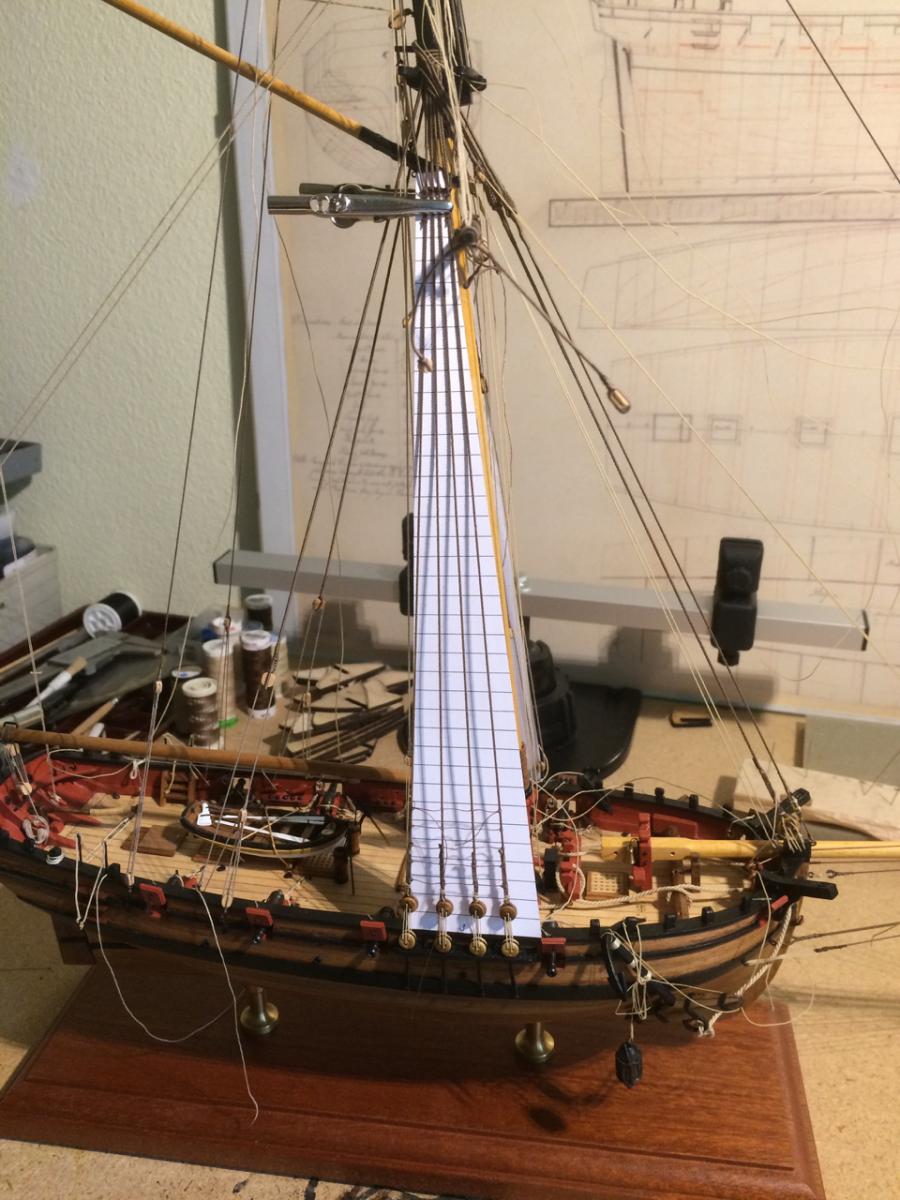
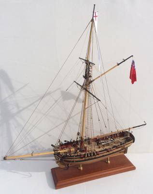
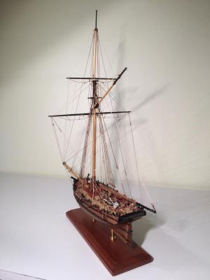
I spent quite some time now with rigging. The latest addition to my Sherbourne is a bobstay; as I learned it’s really an important part that prevents the bowsprit being lifted upwards. Tony has started an interesting discussion about the subject here: http://modelshipworld.com/index.php/topic/8646-bobstay-for-bowsprit-on-sherbourne/?p=256873 My bobstay goes from a hole in the stem to a fourth eyebolt under the cranse iron, is fully served and has two double blocks. Only after that was in place I dared to belay the backstays and topmast backstays. Both are inspired by Chuck’s Cheerful (the plans have been published now). They are rather far aft, but not as much as on the original plan. The running rigging has yet to be belayed, much is hanging loose. I think it was necessary to test all the lines with their belaying points so they do not cross or chafe on each other, thankfully that went well. Next I will do the ratlines, anchor cables and, lastly, the braces. There will be some flags, I think, something mostly red with a cross will look nicely… (Further research in the matter will be needed). My best wishes for New Year Gregor


- 210 replies
-
- 6
-
-
- Sherbourne
- Cutter
- (and 5 more)
-
Kester, with my best wishes: Yes, I quoted directly from the table on the NMM plan. And thanks, Druxey, you are correct, of course; my wishes to you, too. Gregor
-
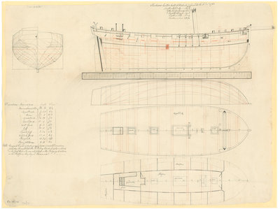
I hope Kester doesn’t mind me answering Kurt’s question: Yes, the model Petersson is showing has a very much younger and more modern rigging than cutters of 1763 had. I’m guessing the model’s rigging is even younger than the contemporary model hull. The Sherbourne’s rigging was much more complicated. The best reference is Peter Goodwin’s book “The Naval Cutter Alert” of 1777 (http://books.google.co.uk/books/about/The_Naval_Cutter_Alert_1777.html?id=XlytPAAACAAJ). But we have to be careful there; the Alert is bigger, younger and from a different yard. I believe Kester is following the Alert as nearly as possible. I did something completely different with my Sherbourne. But I find this topic very interesting, so I opened a new thread here: Let’s hope there will be a fruitful duscussion. The plan of the Sherbourne of 1763 gives us the following details: Mainmast to pole head 22 yards 10 inches (diameter 15 3/4 inches) Topgallant mast 7 3’’ (6 ½’’) Boom 14 19’’ (10 5/8’’) Spread yard 11 9’’ (7 1/8’’) Gallant yard 9 0’’ (4 5/8’’) Gaff 10 0’’ (7 3/4‘’) Topsail gaff 2 24’’ (4 5/8’’) Crossjack yard 12 0’’ (6 ¼’’) Bowsprit 15 24’’ (14 7/8’’) Flying jib boom 9 15’’ (6 1/8’’) N.B. Ringsail driver and studdingsail boom of usual dimensions for cutters. The mast head (…) be 13’ 6’’ long which length includes in the pole head. I couldn’t find an illustration with these specifications. Most interesting is the Flying jib boom… A happy New Year, Gregor
-
Many builders of the Sherbourne kit try to improve the small cutter; their most important reference is Peter Goodwin’s book about the cutter Alert of 1777. But the more I’m thinking about this subject I find that the Alert might be the exception to the rule; and Alert is also is bigger, younger and from a different yard. Especially for the rigging many questions remain unanswered in Goodwin’s book, i.e. a belaying plan is missing. Even more curious: The plan of the Sherbourne of 1763 gives us the following details about masts and spars: Mainmast to pole head 22 yards 10 inches (diameter 15 3/4 inches) Topgallant mast 7 3’’ (6 ½’’) Boom 14 19’’ (10 5/8’’) Spread yard 11 9’’ (7 1/8’’) Gallant yard 9 0’’ (4 5/8’’) Gaff 10’0’’ (7 3/4‘’) Topsail gaff 2 24’’ (4 5/8’’) Crossjack yard 12 0’’ (6 ¼’’) Bowsprit 15 24’’ (14 7/8’’) Flying jib boom 9 15’’ (6 1/8’’) N.B. Ringsail driver and studdingsail boom of usual dimensions for cutters. The mast head (…) be 13’ 6’’ long which length includes in the pole head. I couldn’t find an illustration with these specifications. Most interesting is the Flying jib boom… Is anybody out there able to draw a simple picture of this rigging? Does anybody know something about a jib boom on cutters (whose bowsprit is supposed to be movable)? A happy New Year to you all, Gregor
-
Hi Kurt I bought this one: http://prints.rmg.co.uk/art/494933/plan-of-the-sherborne-1763 Cheers Gregor