


Gregor
-
Posts
225 -
Joined
-
Last visited
Content Type
Profiles
Forums
Gallery
Events
Posts posted by Gregor
-
-
What a pleasure it is to look for the many small things you added - she's a jewel.
Cheers,
Gregor
-
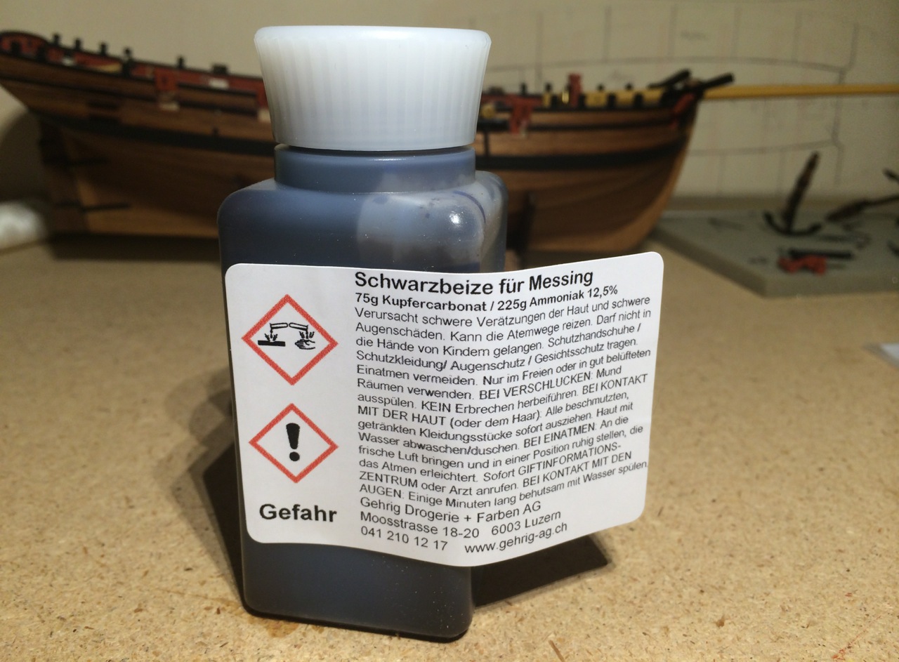
Great, Jan, your blackening agent definitely smells better than my ammonia, and it seems to do the job! On the market your process should get an "organic" label.

Thanks for sharing the fun and info!
Gregor
- egkb and Hollander-jan
-
 2
2
-
-
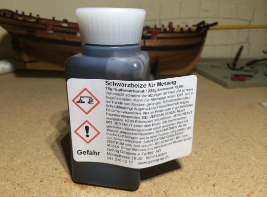
Jay, finding this solution should be easy, but maybe my translation skills are too limited: With chemist I meant not a person but a chemist's shop or drugstore, where (in German speaking countries) they sell everything from non-prescription health products, household chemicals to glue and paint. The ingredients are openly available; the recipe is I on the label.
But this solution works only with brass (called "Messing" on the label) - leftovers from silver soldering are not blackened this way, sadly.
Gregor
-
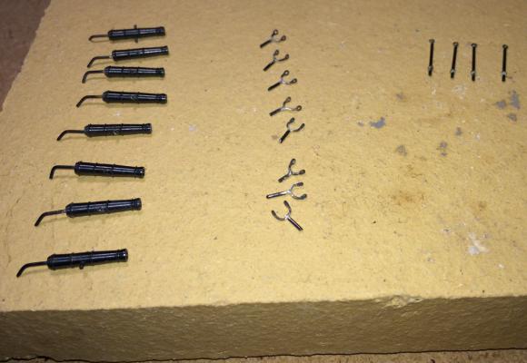
Thanks, gentlemen, for the encouragement. Here just a short follow up to the blackening of my guns.
One advantage of my chemist’s solution (no secret, he just looked it up in his database) is that you don’t need to experiment with adding water or heating up the liquid in a microwave oven. It’s cheap also, but there is a price to pay: you have to work outside, and be careful. The ammonia and copper carbonate did their thing within the hour.
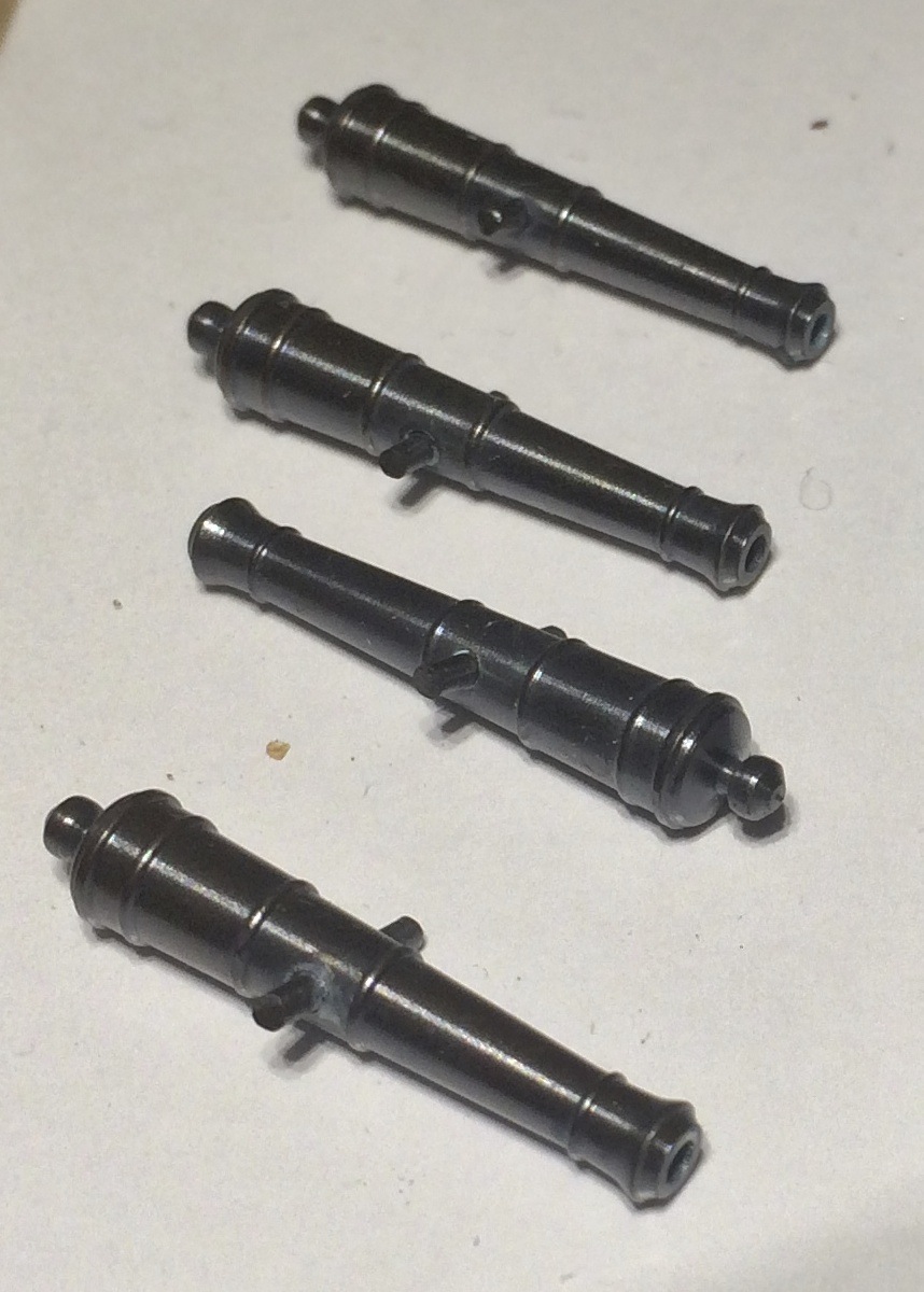
I had bought my barrels last year from Poland’s RB Model, they are 25.5 mm long and looking quite elegant, in my opinion. This is how the barrels looked coming out of a water bath, before polishing with a cotton towel.
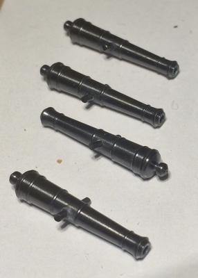
Of course, now I have to find a way to improve my carriages…
Cheers,
Gregor
- Mirabell61, egkb and Dubz
-
3
-
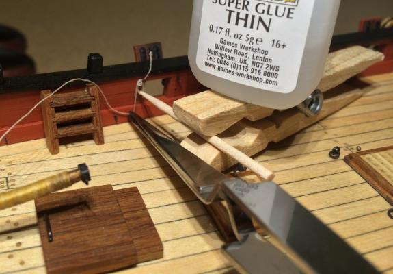
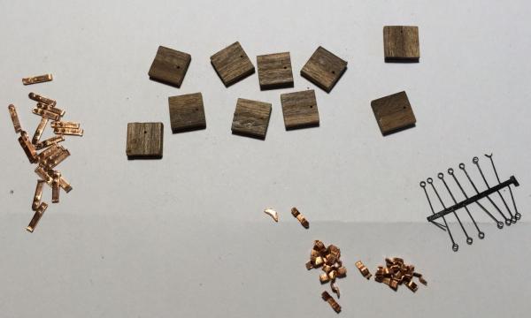
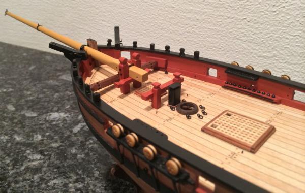
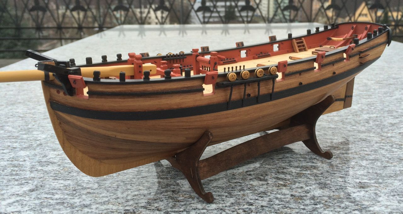
The pin rail situation has been partially solved. There was room for 6 additional pins on each side, five holes can be seen here on the picture. I added another very small piece of wood towards the bow, with a hole for one more pin.
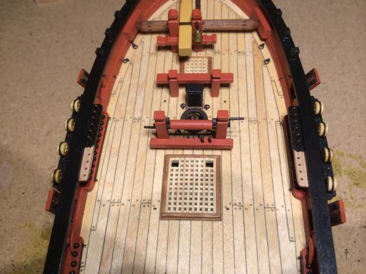
I made also a pin rail under the bowsprit, with four pins. My archaic windlass offered no possibility to ad something there. If the rigging develops a complexity that I cannot imagine at the moment, there will be room for more pins on both sides at the bulwark. And yes, the windlass has now standards – when looking at Dirks log I decided not to take a shortcut here.
Sunday afternoon I spent soldering. The brass swivels are from Caldercraft, treated as shown in Dirks log. My stanchions are simpler, though. I soldered small rings to a brass wire (0.8mm).
The problem now is blackening. After trying out the solution by Krick, I got a better result with a mixture prepared by a local chemist: It works perfectly with brass, less so with soldering leftovers. Stanchions, handles and pintles I will have to paint, the swivels themselves are almost clean, with traces of rust … With the big guns I will be extra careful.
Chers,
Gregor
- Stockholm tar, Hollander-jan, egkb and 5 others
-
8
-
Before gluing gun posts and timberheads, you might have a look at the original plan. If you want to add a ladder, you should probably change the position of some of them (see my log, or better still, Dirk's log - his gun posts are better placed than mine, for a gunner to serve the aftermost swivels). I filled some of the holes with spare wood and made new ones where necessary.
Take your time deciding where you want to place swivels and ladder (see also Kester's and Tony's log).
Gregor
-
Great, Jan - just take it as easy as you can, and never hurry (this is supposed to be a relaxing alternative to stressful occupations; at least it is for me).
When I see an especially beautiful detail that another builder has made, I try to copy it, if I can or to make something similar, but simpler - or I let it go all together. This kit has given me almost two years of pleasure so far, and I'm in no hurry to finish quickly. This mind-set allows me even to remove things, to try to make a better version (many do that here, sometimes to an astonishing degree, and I take courage from their example).
Cheers,
Gregor
- tkay11 and Hollander-jan
-
2
-
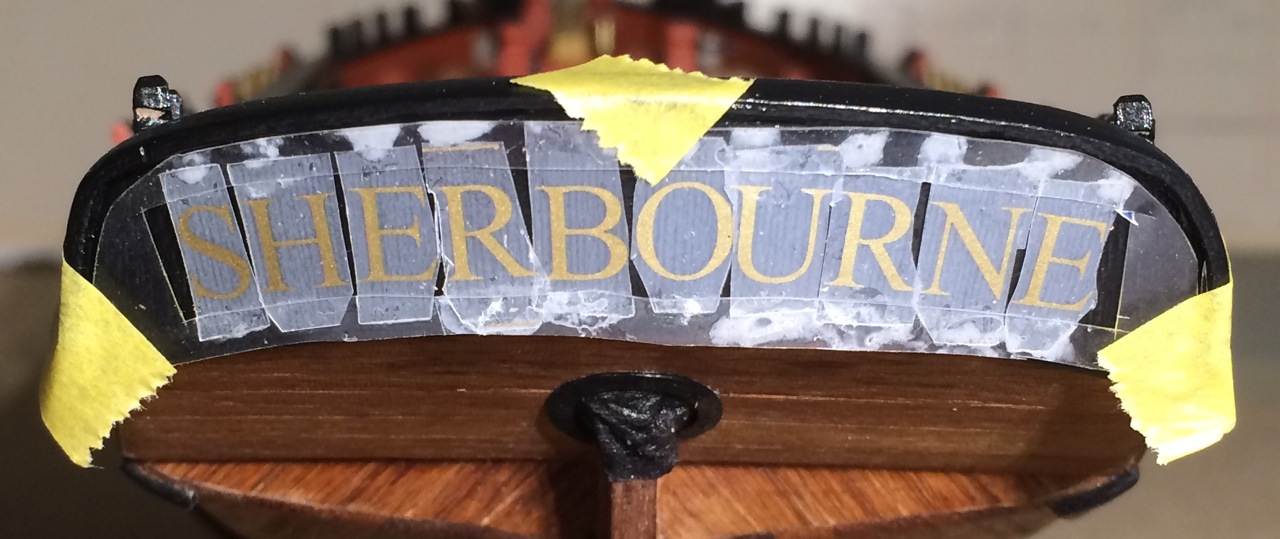
Last week I felt it was the right moment to give my cutter her name. I didn’t like the letters in the kit (metal, font style), and when I saw what Blue Ensign did with his Pickle I started to search for Letraset letters – I thought them to be extinct, but to my astonishment they are still available. They are actually a little bigger than 5mm (23.5p). It’s Times New Roman, also from the 1930ies, but it is an antiqua, Garamond-kind of font, much in fashion since the 16th century.
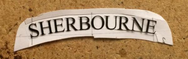
With a graphics software I made a mask on a foil used for overhead projectors (totally 20th century, also still around), cut on three sides, and placed the individual letters over the mask.

A cut on the fourth side removed the black letters of the mask and let me rub the golden ones on the transom. Two coats of satin varnish sealed them.
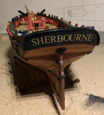
I became quite an expert in sanding and repainting, but that’s in the past now…
I also made some kind of relieving tackles to secure the tiller – a perfect preparation for gun rigging. The four 2mm single blocks are Chuck’s of the Syren Ship Model Company, and I used Dafi’s hooks with them. I still haven’t mastered the art of seizing yet.
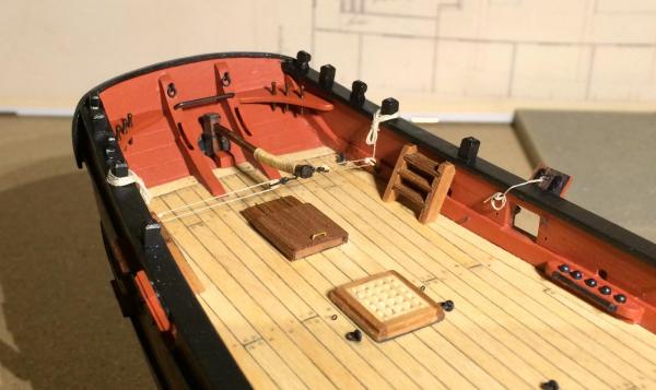
Then the pin rail crisis appeared. So I tried to copy Dirks knees, and the boom traveller. I aborted the removal of the two cleats after hearing the ugly sound of suffering wood. I think the knees make a very nice (an useful) addition, but it will make the loading and firing of the swivels all the more awkward for my crew. Dirk's and Kester's gun positions are much more reasonable.
And yes, I made sliding hatch number four – a side result of Tony’s post no 139. It’s smaller etc. and turned again (I still read the NMM plans differenty, but I see less conflict with the helmsman this way).
Now I will have a closer look at the pin rail situation in Dirk’s und Keser’s log.
Thanks for all your help,
Gregor
-
Wow, Kester - finally I get a real close look into that little box you made so lovingly! But more important, I love the backstay and I will try to copy your idea.
It's not only a question of teaching; it's also the method of asking questions like "what if she had backstays like Alert?" that inspires others.
As I'm still struggling with nautical terms and a general understanding of rigging - may I ask you for a close-up picture of the masthead? This would really help me to understand what you have done.
Thank you, Kester, I learn a lot here.
Gregor
-
Hi Jan. Chuck offers an excellent guide for assembling the parts of a gun carriage. There you can see how the "wire" holds the two sides together.
Cheers,
Gregor
-
I'd be very grateful too to see how it's really done - like many of the cutter-kit builders I use the alert as a reference. So if you find the time not only to build a beautiful model but also to explain how you do that, it would be very generous.
Cheers,
Gregor
-
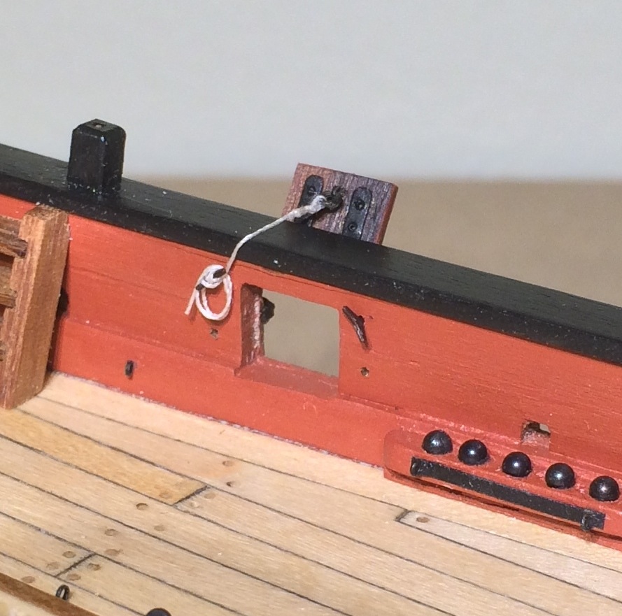
The question I was mulling over for quite some time was: How to secure the open lids? There is no room between the gun ports and the rail to lead a rope through a hole (or tube) to the inside of the bulwark. Such an arrangement would leave the open lid in a horizontal position. So the rope had to go over the rail.
There is an example for that: Le Renard, a French privateer cutter of 1812, that was rebuilt at St Malo and is now a tourist attraction.
I had Le Renard (enjoy the pictures and imagine a sailing Sherbourne) in mind, when I built my lids.
There was also not enough room to mount the cleats between the rail and the gun ports on the inside (there would be even less room if we followed the original plans). So I put two of them on each side of a gun port: one for the rope that holds the lid open, the other for a rope that would keep the lid close. Curiously, the second one is rarely shown on models (or it was removed when the lids were open?).
This arrangement made it “easier” to knot the rope around the cleat, two turns are also slung around – probably not enough to close the lids completely, but enough for me.

Diluted PVE was applied to hold the knot (which is not properly done) together. Now there are nine others to do.
Cheers,
Gregor
-
Oh, oh, this deserves more than a simple like! What I admire most: The idea of rethinking and doing it again in a new way.
Gregor
... and after rereading the post I have to add: Not only the results are inspiring, but also the techniques and with them the proof that - with much effort and ingenuity - there can be much progress.
Thanks again, Tony!
-
Well, Tony, we either have to learn the art of sailing or follow one of the masters. But I really don’t know yet what I will do rigging-wise. There is much to do on deck before it comes to that.
One thing I started around Christmas I can share now: Last September we had a small discussion about gun port lids. It was then that I decided to make my Sherbourne looking a bit like the cutter Fly.
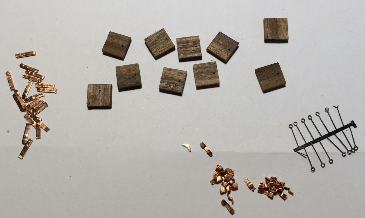
My lids are made of 2mm walnut strips, with copper hinges. I utterly failed to make cleats (I even tried to make tiny cleats from 0.3mm eyelets…), so I contacted Dafi (of Victory fame) and bought a brass sheet full of rings, hooks and cleats. They will last me a very long time.
All lids are shown in an open position; even the two at the bow – when I closed these ports, the too thick upper gunwale was really standing out very clearly. This has the advantage that there was no need to make actually working hinges (what an excuse!).
Of course, my gun ports have no inner frame, so a very simple board would do here. I googled a lot of gun ports, where I found many different types even on a Victory, and in the end I decided – simply for aesthetic reasons – to file around three edges to make the lids “lighter”.
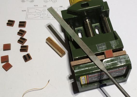
I also made a very simple jig, which I put in the gun ports before gluing the lids to the hull.

There were many dead ends and discarded pieces, but I’m quite happy now. Old mistakes came around to bite me, though: The curve of the hull does not exactly match the curve of the capping rail, so not all the lids open to the same angle (even with a little bit of cheating). And even worse: In my early days I did not pay enough attention to the upper end of the bulwark patterns that came with the kit. In fact, I found them quite elegant at the time, like a car from the 1970. But now the lids are showing clearly that the rails before the chains lie higher over the gun ports than aft of the chains.
At the moment my lids are defying gravitation, but I can live with that, at least for a few more days.
Cheers,
Gregor
- tkay11, Hollander-jan, WackoWolf and 4 others
-
7
-
Thanks, Kester and Tony -
When I read that "on full-sized vessels belaying was always logical" (Alert - Provenence and Construction, by N. Roger Cole Download ) I had a good laugh. Even after a beautiful week of Mediterranean cruising in a single master I couldn't understand how our friends and the skipper always knew which rope to pull.
My pins are there because I thought I had detected six holes in Tony's cross piece. They are not on Goodwin's Alert reconstruction, but are looking nice, and the holes had to be filled with something. The second reason was that George Bandurek's belaying plan shows a few belaying points (he called it five rail) where we have the jeer bitts. As I have absolutely no idea of what (in the form of ropes and the like) will come from above, I thought it a good idea to have the pins ready.
Kester, I remember having seen the concept of rope stoppers in Dafi's Victory log. So I can proudly say that I have seen it in action on our diving boat after our anchor winch blew out.
But I saw that you have no pins on your cross piece, and your jolly boat would make it very uncomfortable for the crew to belay anything there. I will be very grateful to discover in your log where you are belaying what. And I will gladly come back to your explanations of the rigging when the time is ripe. It will be hard to follow, even when I try a translation into German, where (very northern) nautical terms are almost as foreign to my southern ears as the English ones.
As for the handles: It's possible to lengthen them temporarily with an iron tube (if the handles are forged by a proper blacksmith, as superglue is not invented yet). We do that sometimes with big bolt cutters (cutting a chain) to have more purchase. But I was also surprised by the almost primitive mechanism of this windlass. Even two cogwheels of different size would have offered a welcome transmission of power (not anachronistic: we are in the early stages of the industrial revolution).
As for the coamings, Tony: I tried to build what I saw on the NMM plans, got carried away and made the main hatch the same as I have done with the scuttles. Next time I had a real look at the coamings on the plan, my hatch was glued to the deck, never to be removed again for fear of destroying the deck planks. (I was tempted, for a time). So I would recommend to do the main hatch as shown on the NMM plans (I don't think the wellbeing of the crew was the most important aspect of ship design in 1763). But then again, we already had discussions about the reliability of the plans. Who knows what modifications were made in twenty years of service.
Cheers,
Gregor
-
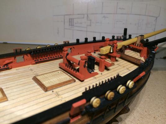
With Tony’s much appreciated help I built my version of jeer bitts with a windlass.
A friend challenged me to make the windlass working – well, it turns around till the soldered handles break (almost instantly, to be fixed with superglue). The pawls don’t stop anything, but were fun to make.
I found another way to make the pawl drums: the brute force method, with pliers and a hammer.
Mounting the assembled jeer bitts, I foresee some headaches in the far future: Belaying will be difficult in the confined space between the main hatch and the cross piece.
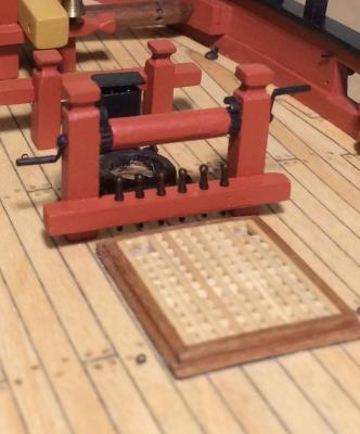
The anchor cables will have to go around the jeer bitts, but this can be seen in contemporary models (the Hawke, in Goodwin’s Alert book).
All the best,
Gregor
-
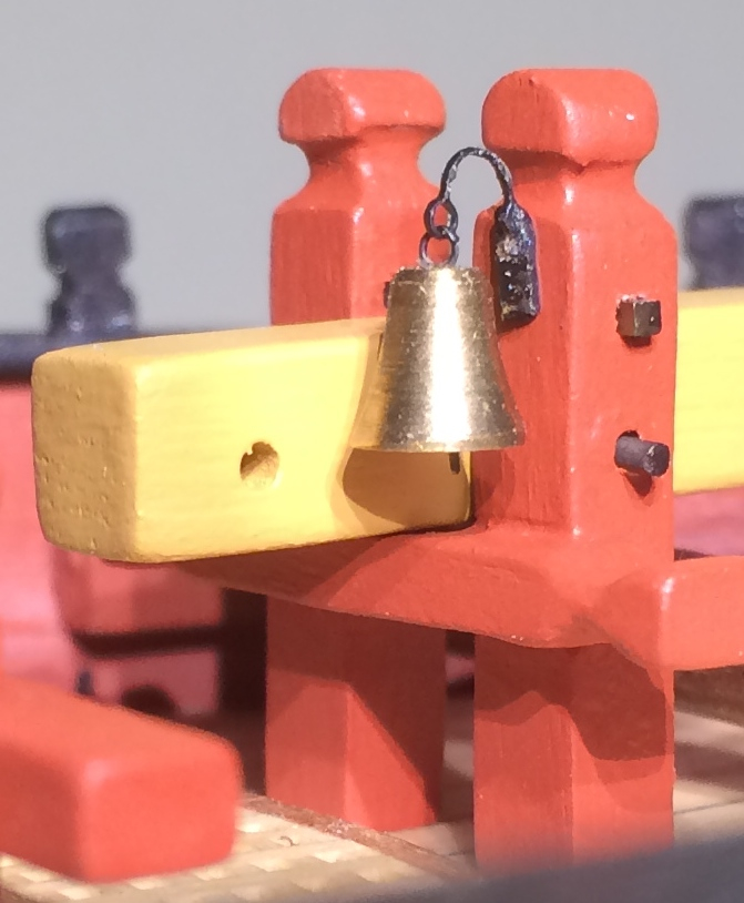
It’s the season. Its pure kitsch, but I had to add it now. Feel free to hum or whistle an appropriate tune according to your personal taste or custom.

The brass bell was a gift. I used two 0.3 mm brass eyelets and a small piece of copper to mount it.
Merry Christmas and a happy New Year to you all. Thank you for all the encouragement and wisdom. I’m very much looking forward to seeing you again in 2014!
Gregor
-
Welcome to the fleet, Jan, I wish you much fun and satisfaction with your Sherbourne. I will follow your log closely.
Cheers,
Gregor
-
Thanks, Jay, Kester and Tony for the kind words, and good health to you all.
I'm really enjoying how every Sherbourne builder makes his or her own choice of how far he or she will go to get nearer to the no longer existing and somewhat elusive original (Jay's decision to build a Sherbourne from scratch is the ultimate consequence of this quest).
For me the kit provides a solid beginners platform which can be altered or improved individually to an astonishing degree, as you and other builders here demonstrate.
With the best wishes,
Gregor
- Stockholm tar, egkb and Jay 1
-
3
-
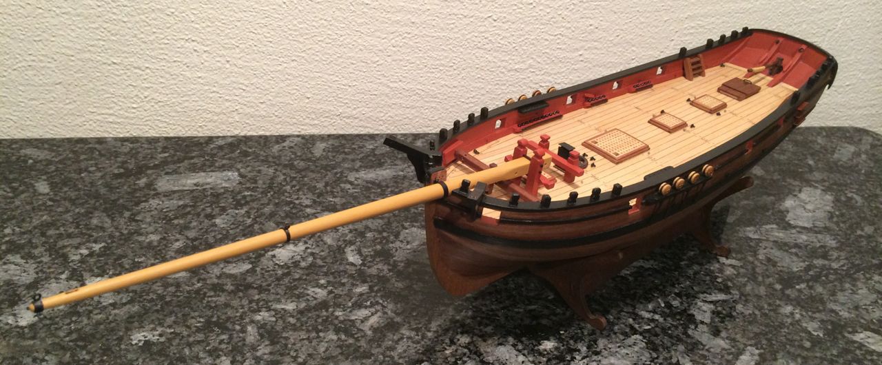
It’s rather quiet in the Sherbourne yards at the moment, certainly it was in mine. Over the last few weeks I took tiny steps towards the bowsprit. A lot of small things hat to be finished (the rail, catheads, stairs) first.
I used the dowel provided in the kit, but added a piece of square wood at the rear end (a cheap thing I found in a local hardware store – too soft and too easy to bend to use as bowsprit) with a small round dowel glued inside for stability. The tapering was made by hand. Adding a piece of wood was no problem because I wanted to paint masts and spars anyway, so several layers of yellow ochre cover up nicely.

The bowsprit support was made with the parts provided in the kit. I cut away the “connecting pieces” and added two holes for the iron strongback and the retaining fid (1mm square brass rod).
To complete the bowsprit assembly I finally had to learn soldering. The iron hoop, the cranes iron and traveller were made with copper strips and eyelets. I had to remove a lot of molten pieces before shooting these pictures…
Cheers to all,
Gregor
- riverboat, egkb, Mirabell61 and 3 others
-
6
-
B.E., you got me thinking and speculating. I can imagine that swivel guns could have been stored below deck sometimes. At least they should be properly secured when not in use. On many models we find fully rigged and secured guns, while the swivels are “flopping around” – injuries waiting to happen.
Gregor
PS: See, Tony, now I’m posting in your log (I apologize – but let’s do that more often
 )
) -
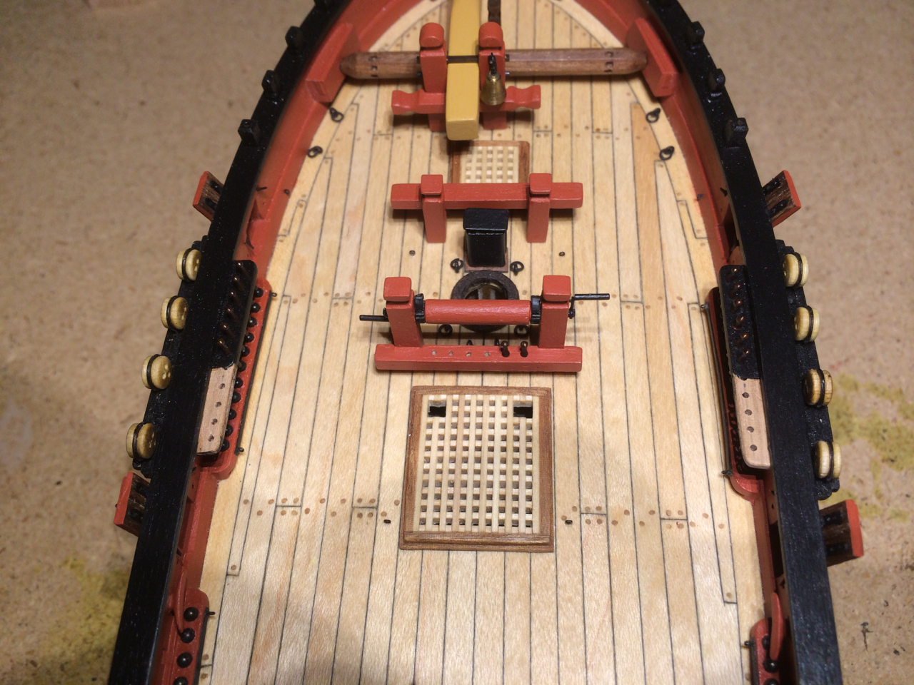
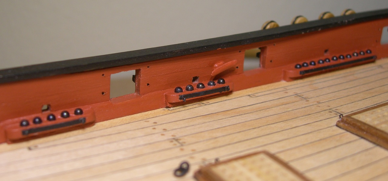
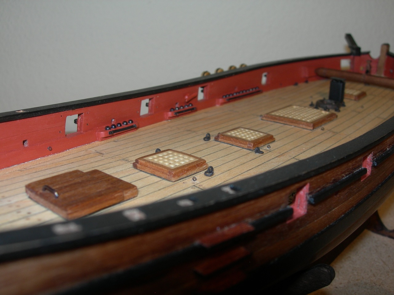
Tony’s update motivates me to make a picture of my interpretation of the shot racks, made from 4mm spare wood strips, sanded down to 3mm to follow the curve of the deck. Even using a stand for my proxxon mini drill, getting a centre line and even spacing proofed very difficult to achieve (at least I tried).
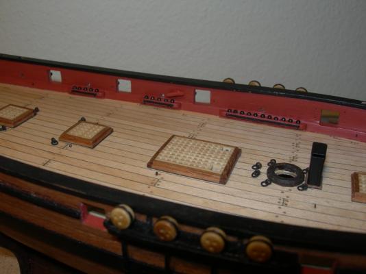
Also, I drilled my holes too deep, so that the balls almost disappeared in them. I had to fill the holes with toy clay before inserting the balls in the holes. There is a metal band (black paper), giving more strength, and two 0.3 eyelets in each for the gun tackles.

I used a paper template to find the spots for drilling around the gun ports. Each has now two holes for the breeching ropes and two for eyelets to make fast the lanyards from the (planned) gun port lids.

I have finally decided not to make a deckhouse – I shortened the sliding hatch I made earlier following Tony’s tutorial to the proportions shown in the NMM plans and glued it to the correct position.
I was a little disappointed when I belatedly realised that my planking pattern does not fit the positions of the main hatch, scuttles and mast, which are cutting through the deck beams. Now I understand why and how Dirk has made his deck plan (another lesson learned …).
Cheers,
Gregor
- Jay 1, Stockholm tar, tkay11 and 3 others
-
6
-
Tony, this gives me a very welcome dose of motivation (like you, I had some difficulties aligning my cannon balls in the shot rack, among other problems…). I admire your jeer bitts very much!
Thanks,
Gregor


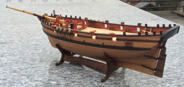
HMC Sherbourne 1763 by Gregor – FINISHED - Caldercraft – Scale 1:64 - first build
in - Kit build logs for subjects built from 1751 - 1800
Posted · Edited by Gregor
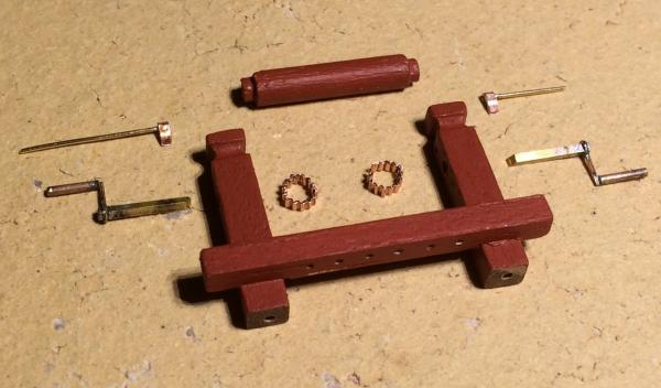
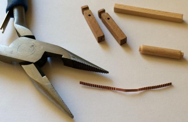
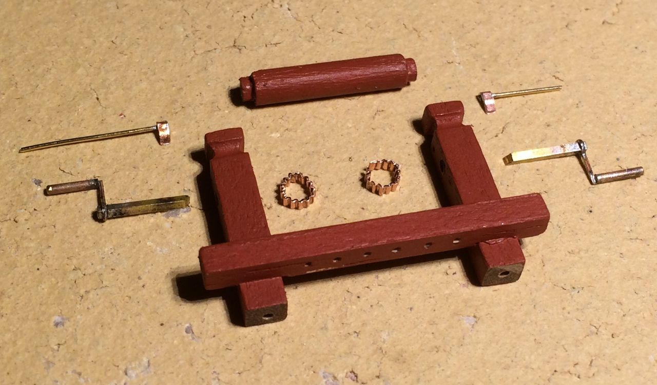
No, Jan, I didn't buy the carriages (they look nice, I agree). At the time the idea was to replace the barrels only. Since then I started to think about making my own carriages (plan A), but that proofed to be more difficult than I imagined, the results have not been very satisfactory thus far.
Plan B is to use the parts from the kit – their man flaw is the length. I scaled down Chuck’s drawing of his twelve-pounder kit. A comparison with the original carriage cheek shows their different proportions.
So I took seven guns apart (they were the first things I built in Summer 2012) and kept one of the originals as a reminder of humbler days. I think it would be possible to make acceptable guns by shortening the cheeks, making thinner wheels (as Tony has shown in his log) and using smaller eyebolts and rings.
I’m still working on plan A, tough…
Cheers,
Gregor