0Seahorse
-
Posts
124 -
Joined
-
Last visited
Content Type
Profiles
Forums
Gallery
Events
Everything posted by 0Seahorse
-
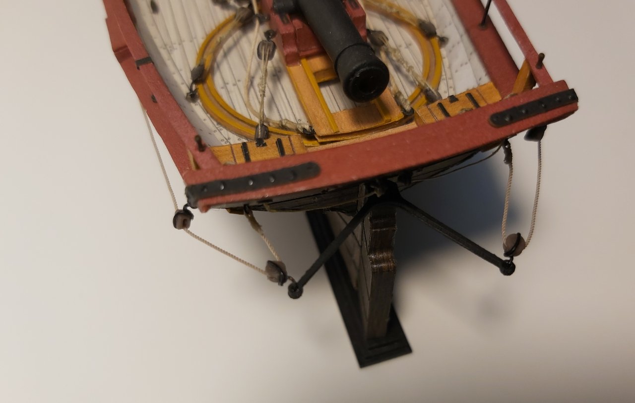
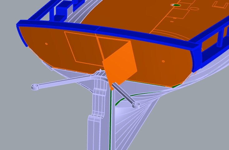
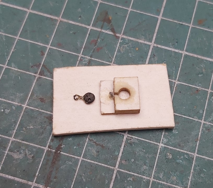
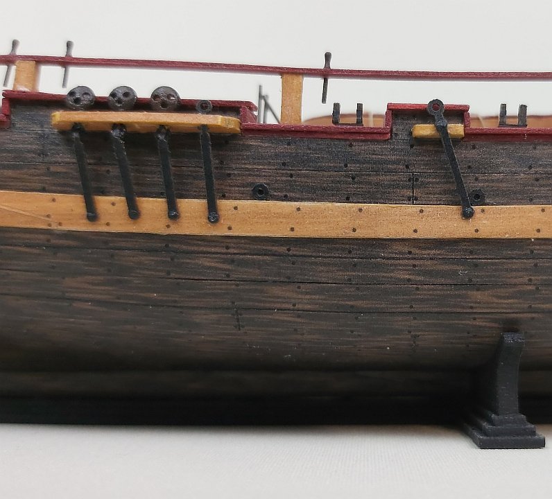
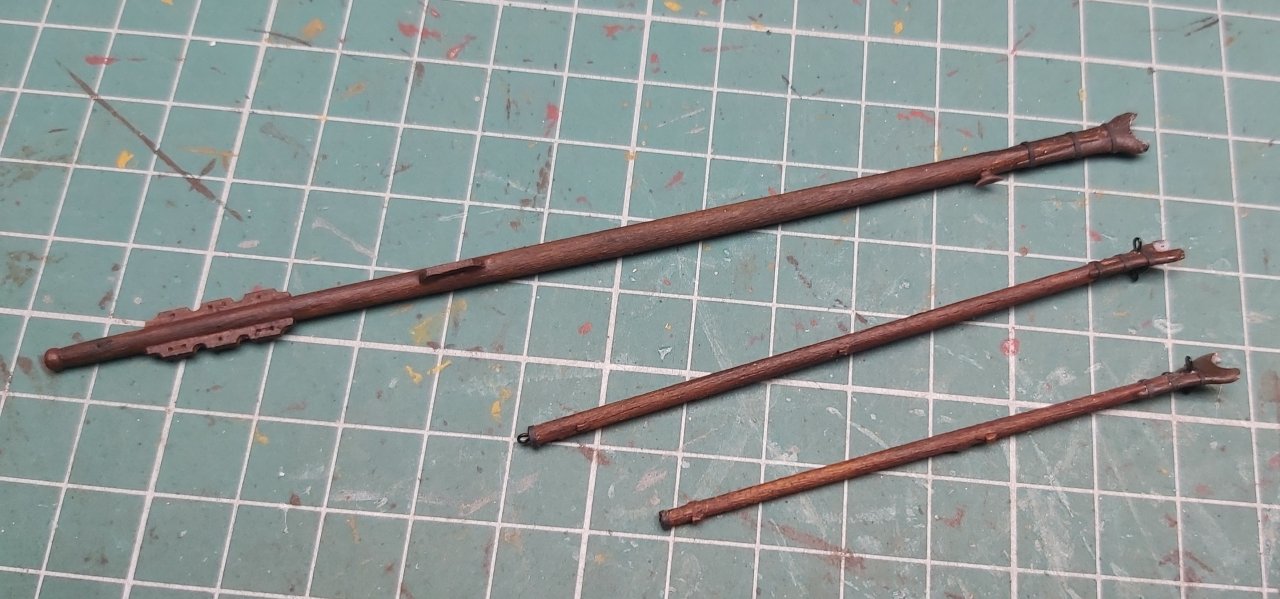
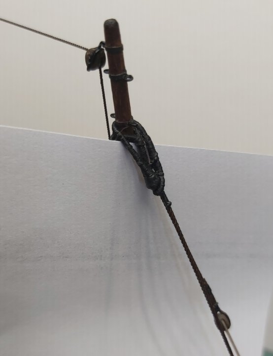
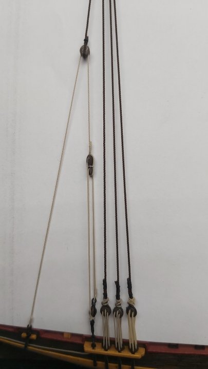
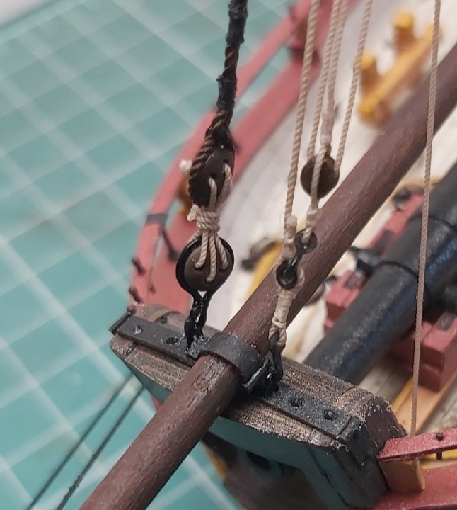
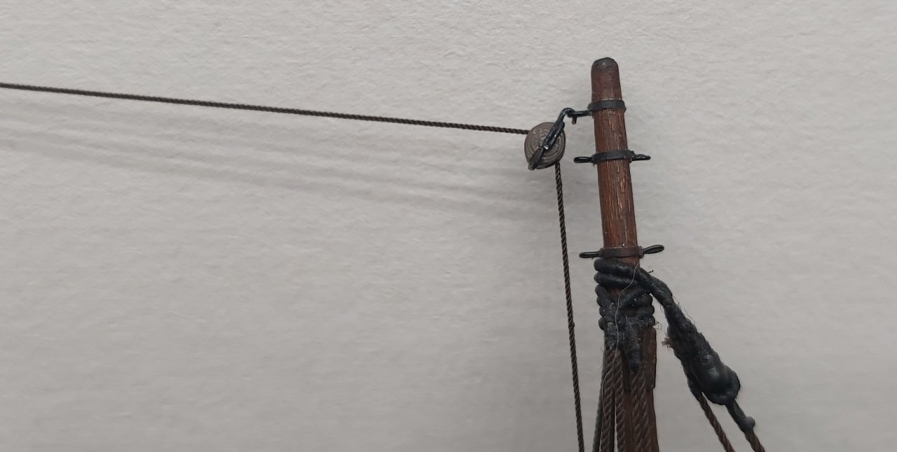
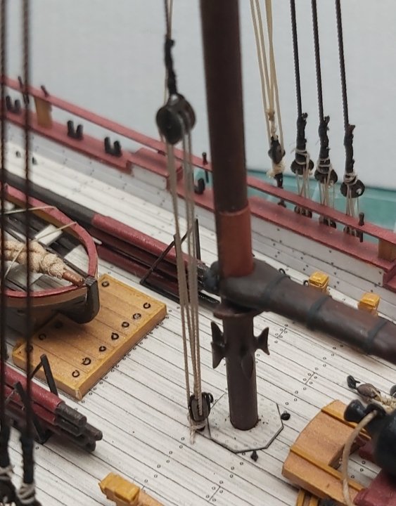
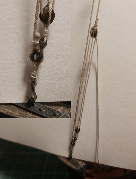
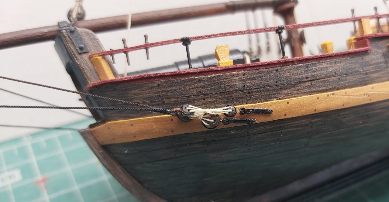
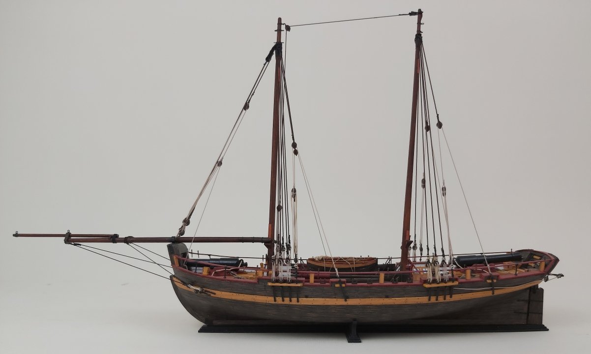
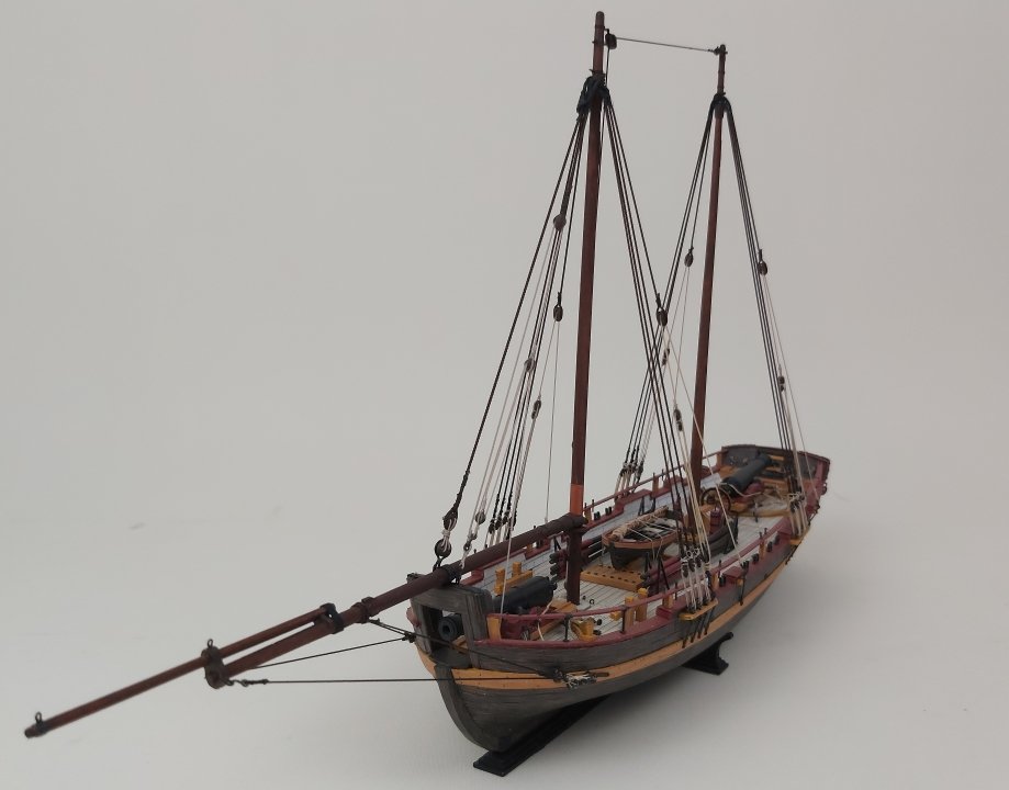
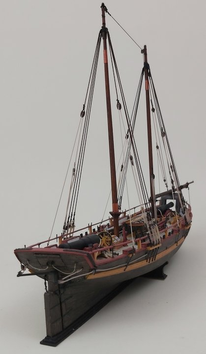
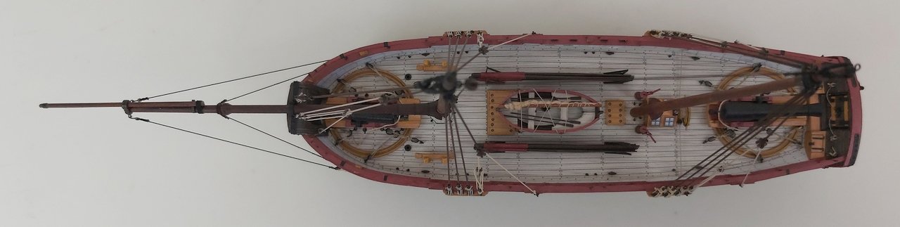
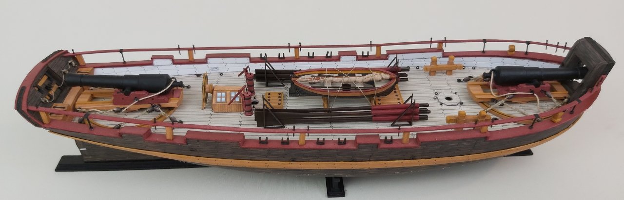
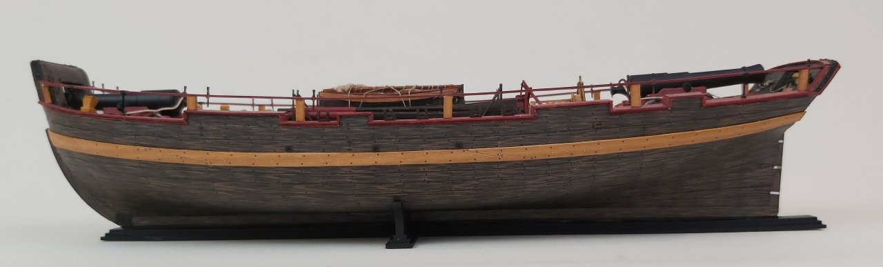
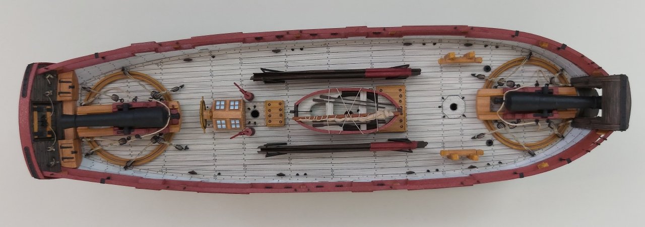
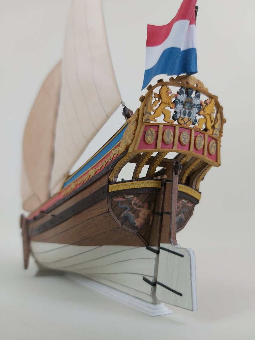
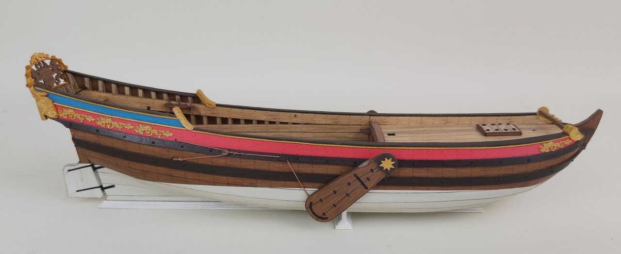
 Hello Colleagues. A long break in the report, so long that I had to remind myself what had been shown and written so far. (off-topic: I made very cheaply real shadowless lighting:-)))) The first conclusions from further work on the model are the necessity to change the order of gluing (in the assembly instructions together with the publication of the model), i.e. the upper handrails on the posts should be glued at the very end, because later manipulation of the hull at the rudder blade and channels ended with breaking several posts, breaking two belaying pins, etc. Everything has been fixed, but twice the stupid job 🙂 Let's start with the rudder blade, which I glued to the sternpost on small tightly wound paper strips pretending to be the rudder hinges. Then I started running the rope that connected the characteristic structure at the top of the rudder blade (let's call it an "inverted double tiller yoke") with the steering wheel drum. This "tiller" should be solidly reinforced with CA glue, or cut out of strong pressboard. Unfortunately, mine is so flexible that I couldn't pull the steering rope tight enough. I ran the rope as a whole, but I was considering two separate sections that would "connect" on the steering wheel drum somewhere from the bottom in an invisible place. Finally, I moved it from one side to the other through all the built-in sheaves and blocks, to finally determine the length, remove the blocks from one side, tie an eyebolt at the end and finally secure everything with glue. The rudder blade was secured with two more chains, which I printed in resin "ready to use" (a chain of the appropriate length finished with eyebolts on both sides). After finishing, I started to look at it and... either I made mistakes in the design, or Mr. Marquardt did not pay attention to the fact that in this configuration the gun port door cannot be opened - it catches on this characteristic "tiller". After analyzing all the materials that I had and found on the net, I noticed that in none of the models these doors are open, except for one, where the shape of this "tiller" was completely changed. It was replaced with a "single one" and then the door actually opens without catching on anything. I have of course checked my inaccuracies in the design, but the difference is so small that the error is probably not on my side. (I write "probably" so as not to start a war 🙂 I do not know what decision to make at the moment, I am inclined to lower the "tiller" by about 1 mm. The shape of the rudder blade would change slightly. The dimensions of the doors and the angle seem correct to me, so this will probably be the best solution. The movie showing the entire assembly of the rudder and the simplest tying of the blocks in Axel Thorsen part 8. So it was time for the channels with deadeyes. These are made as always, i.e. deadeyes covered with wire with an eyelet shaped at the end and the whole thing "sunk" in the channels. I made a quick template, on which I bent the wires covering the deadeyes. After everything was done, the leading edges of the channels were masked with a 0.5 mm cardboard strip. After gluing the channels to the hull, I added strips of black cardboard imitating the chain plates. They should be vertical, but I unnecessarily put markers on the wales, which did not match the channels and these markers had to be covered in some way. Hence the chain plates are slightly diagonal and a bit crooked. (Channels in Axel Thorsen part 9) The spars were roughly turned on a drill using sandpaper, the gaff, boom and bowsprit jaws were 3D printed in resin. Designing and printing them probably took as much time as chiseling, grinding, and sanding them from several layers of cardboard. And the end result is probably better. After painting, I added eyebolts and small fittings. And now it's time for the standing rigging. Both masts are basically rigged identically: three shrouds and one backstay for the side of each mast, only the stays are led in a different way. Up until now, I've attached the shrouds to the masts in the form of a regular loop, from which a pair of shrouds branched. This time it's still a loop, but I decided to improve it a bit visually and did the "serving" manually. Since I started using better ropes (instead of regular threads), there are a few failed places, e.g. I tied the lanyards with different thicknesses of these ropes and the thicker ones didn't want to tie nicely after the shrouds were pulled tight. There is another YT video to watch here Axel Thorsen part 10. "Serving" also concerned the entire stay loop up to the mouse. The mouse had a very characteristic way of braiding, I am not that advanced: I filled the knot with thick glue and braided it with thin thread, giving it a pear-like shape in the fingers on the still slightly plastic glue. I printed hooks from a stronger resin (of course they can be broken or torn off) and this time they withstand the stresses on the cardboard model. With their help I made backstays, so graceful and obvious in their construction that I won't go into detail about them. The forestay is typically tensioned with deadeyes... ...and the mainstay, which first goes horizontally to the block on the foremast... ...was tensioned using a tackle located on the deck just behind the foresail. A visually attractive set of loading tackle, which were used for lifting the "removable" bowsprit and other heavy things. Since we are on the subject of the bowsprit, standing rigging also appears here in the form of bowsprit shrouds. That's it for now, a few more photos of the model: Greetings Tomek
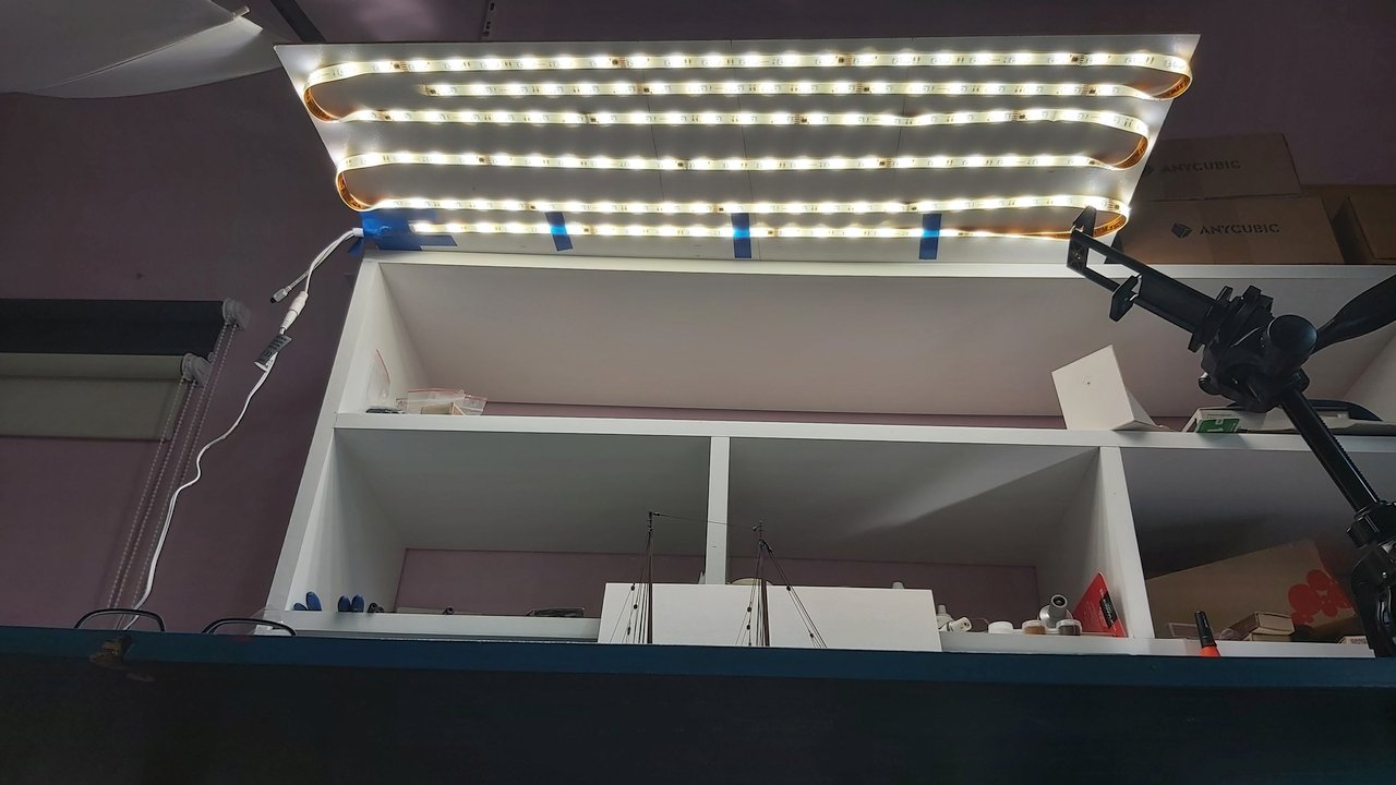

- 7 replies
-
- 8
-

-
- Axel Thorsen
- gunboat
- (and 1 more)
-
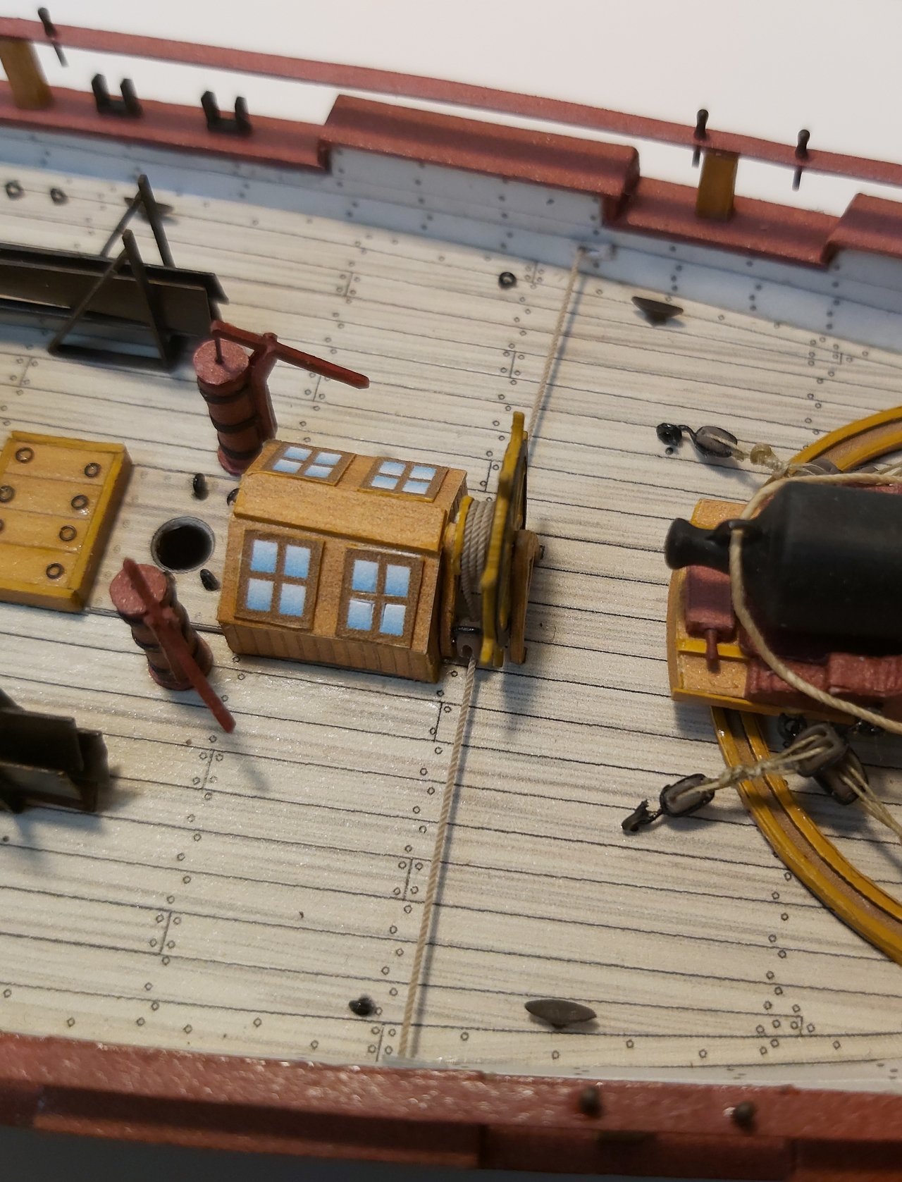
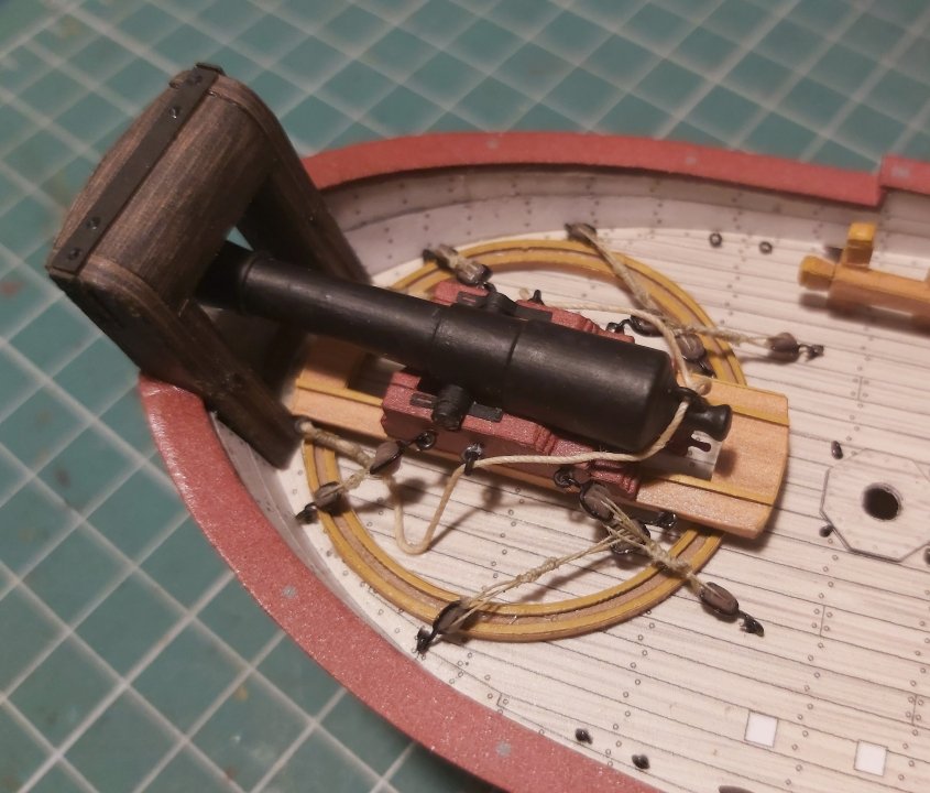
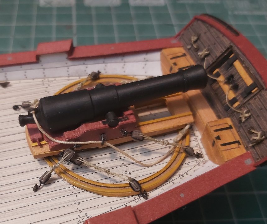
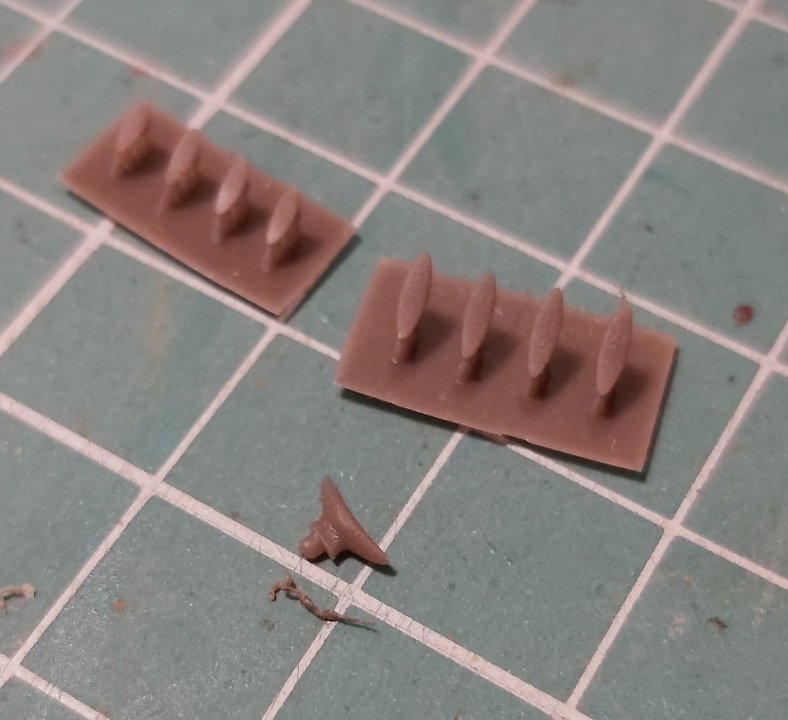
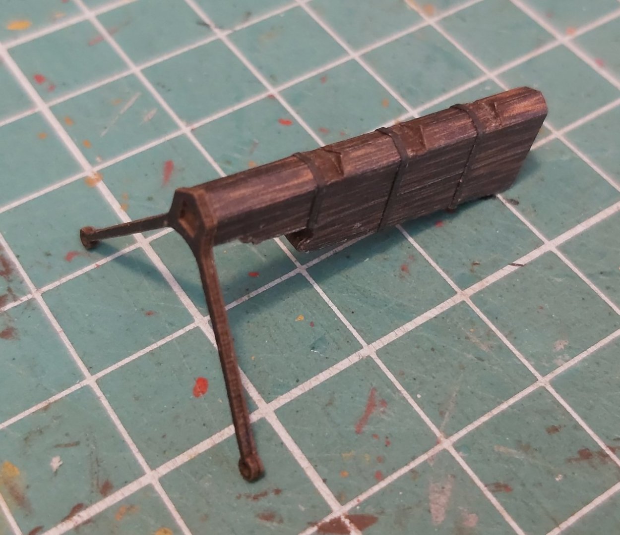
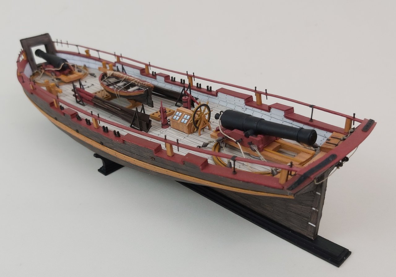
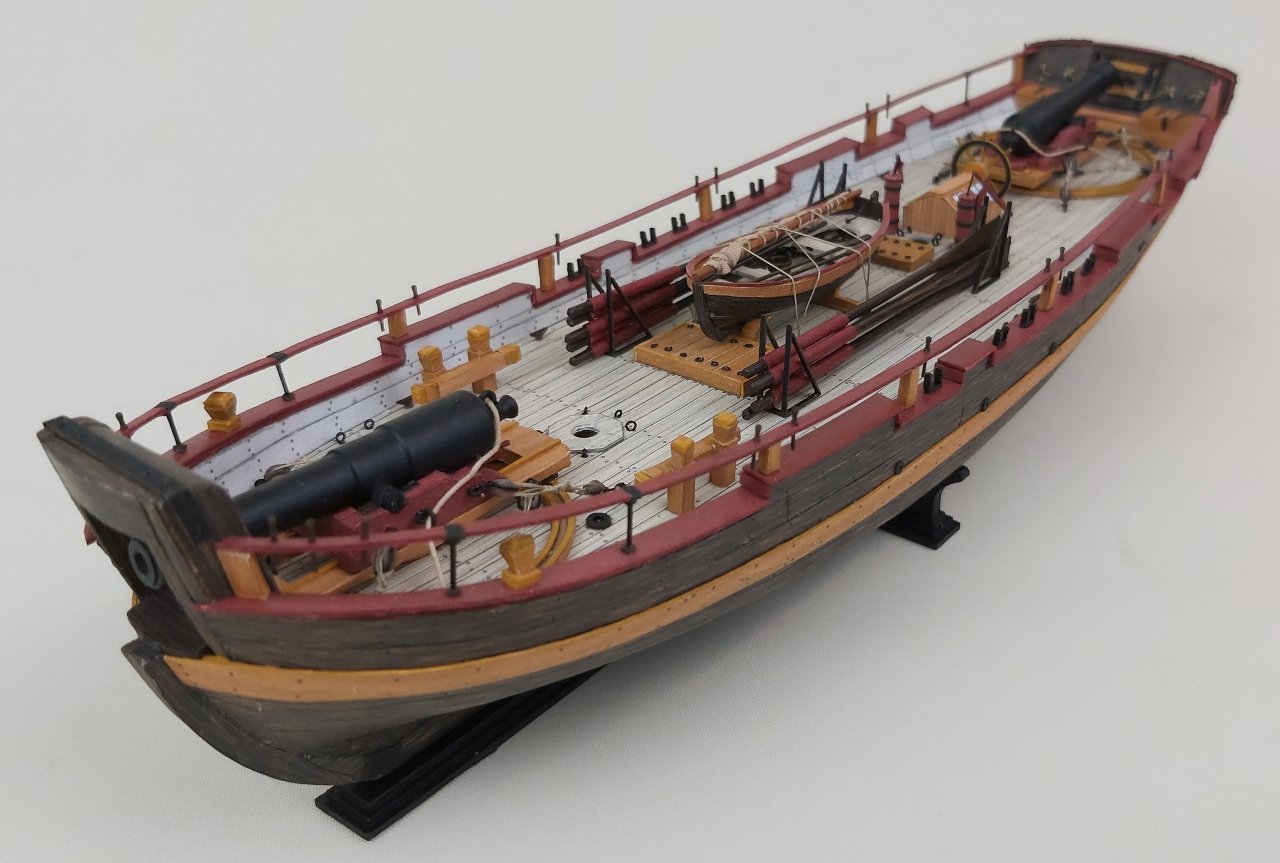
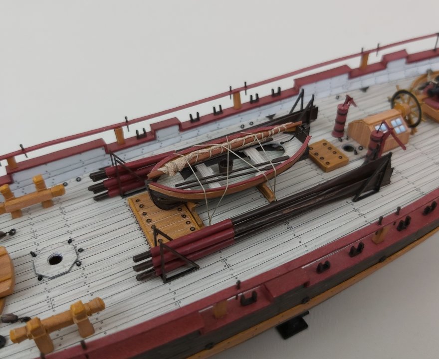
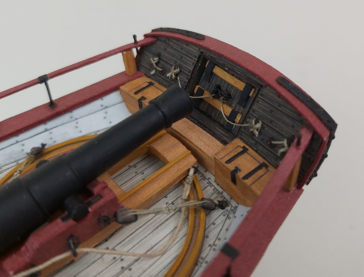
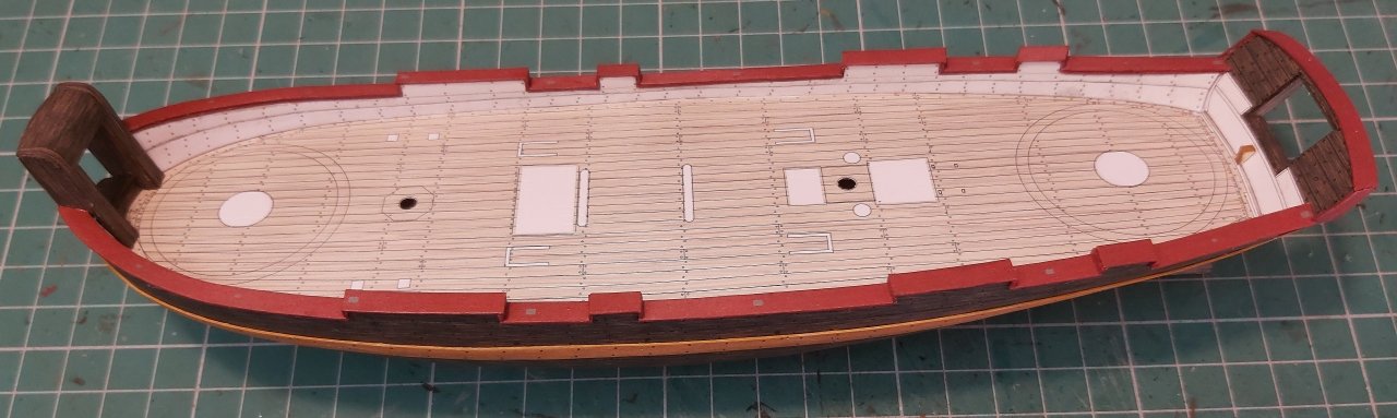
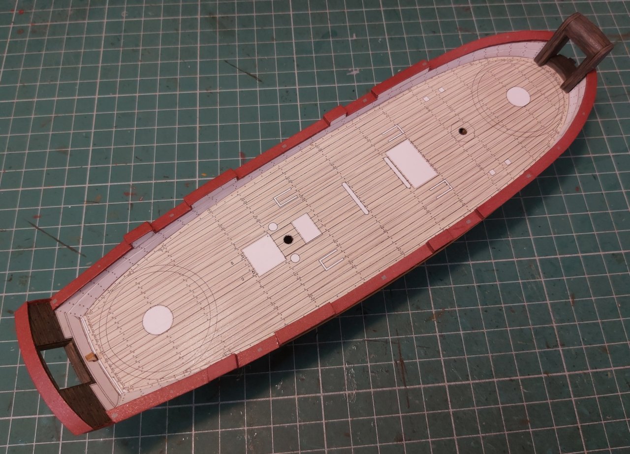
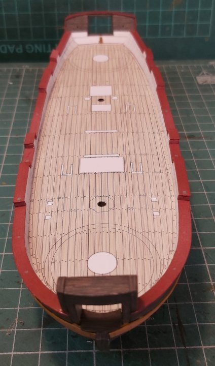
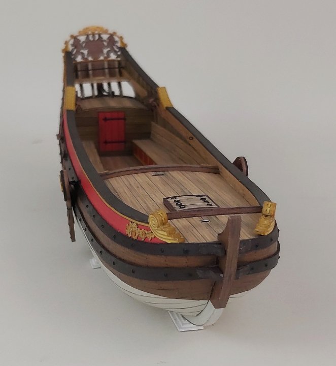
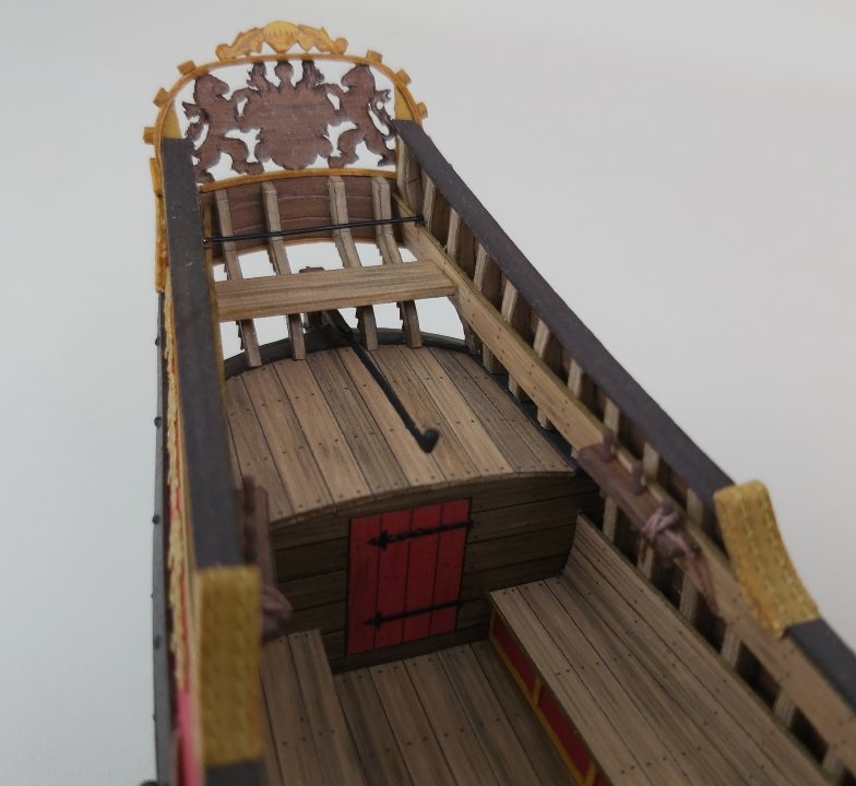
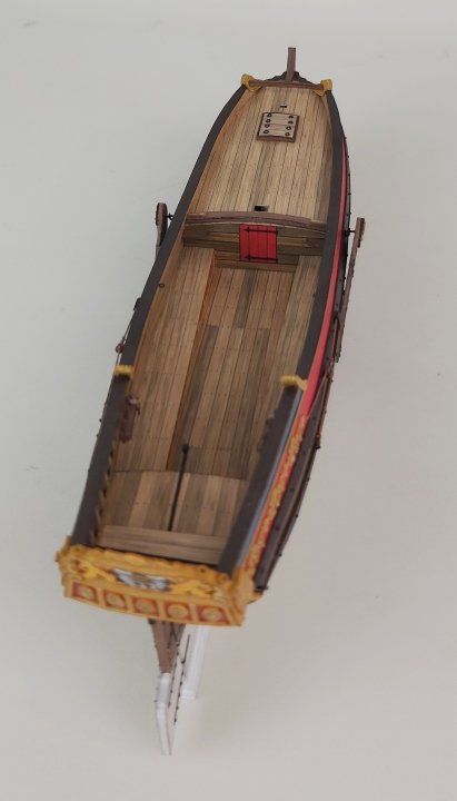
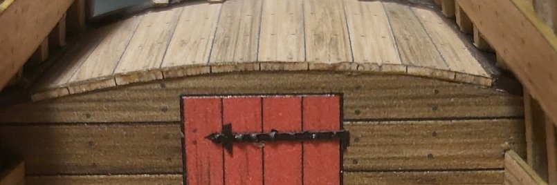
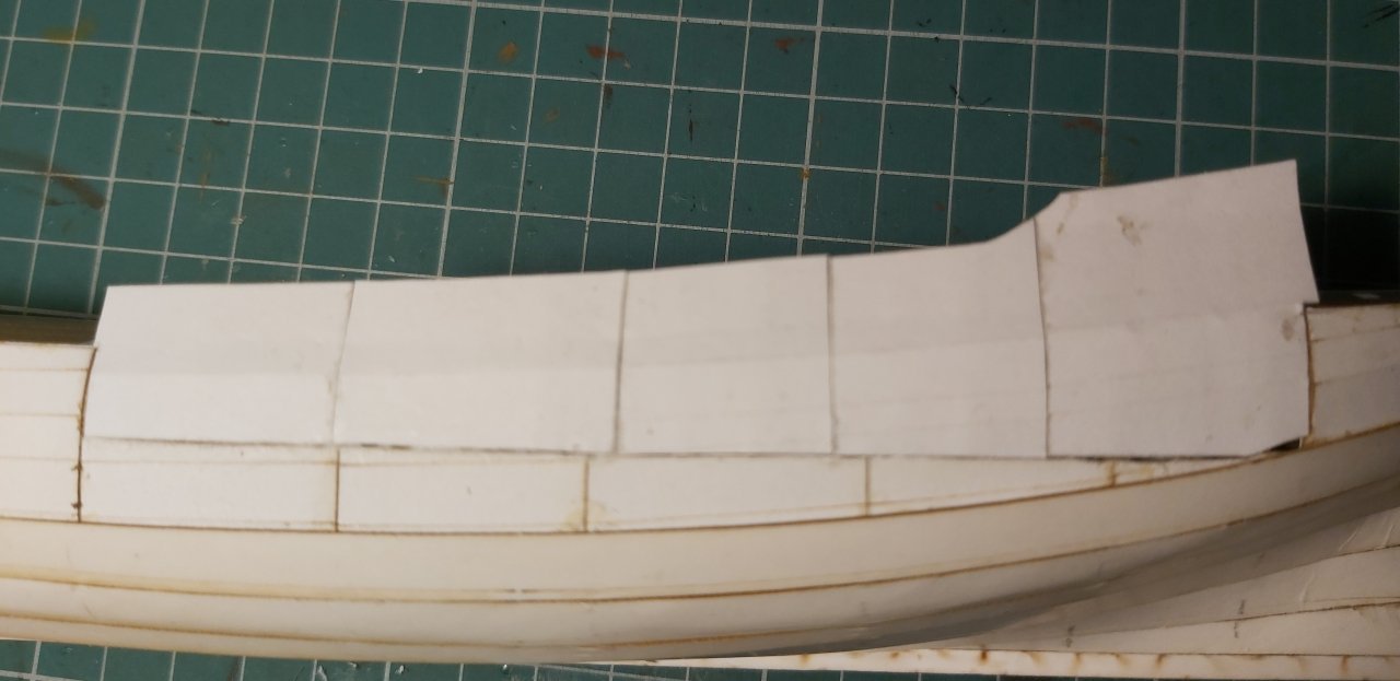
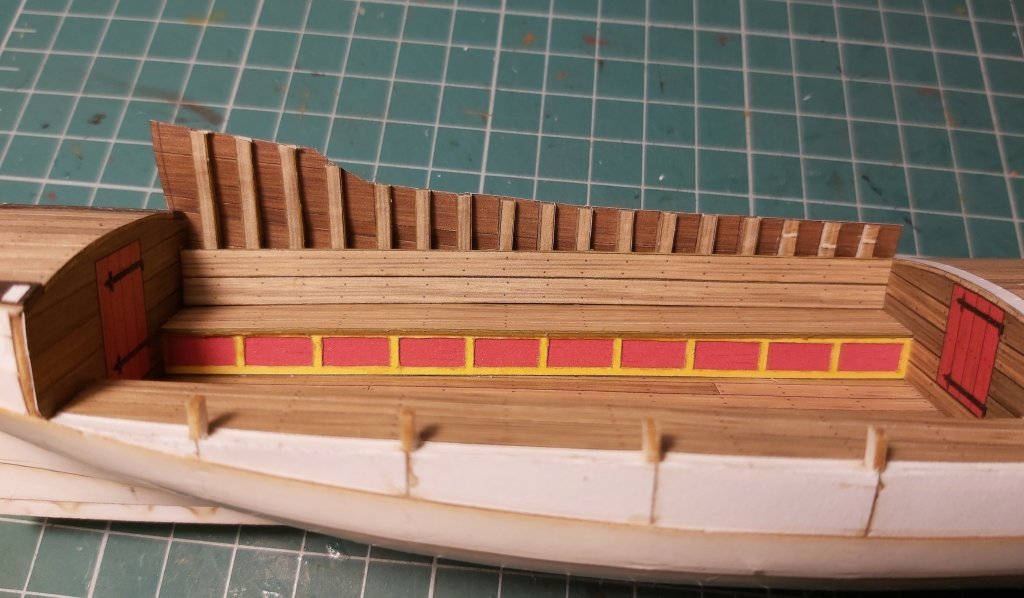
Hello everyone after a long break. The last few months in Poland have been a time of modelling competitions week by week, which take up a lot of time, and that time is needed for gluing the models. That's why I can only now show you what's new on the gunboat. I made all the deck equipment, i.e. the loading hatches with covers, the skylight, the stands for the boat, the eyebolts, the cleats and, most importantly, the artillery. I won't go into detail about the hatches and the skylight, as they are very simple. The track for the gun platform is made of hoops covered with strips, the lower edge of which is to complement the deck arc, so that the track itself is flat and horizontal. The platforms took more work, because they are not ordinary boxes: there are holes inside, and the whole body in the side projection is a bit like a trapezoid at the front, and at the back the thickness of the whole platform is different. Initially, I wanted to do it on some frames and supports etc., but in the end the body was created classically, i.e. cut-shape-glue. The gun carriages themselves hold no secrets. I managed to "carve" tiny steps on the edges - by gluing them with strips and water glue, the whole thing is so plastic that with a sharp tool like a mini-chisel, you can press, wrinkle and obtain micro-steps. Test gun barrel made of cardboard. I finally put barrels from resin prints on the gun carriages and spent some time rigging (6 sets per gun). I closed the doors on the stern and added ropes to them for opening and closing. From the inside, they were closed using crossbeams and this is a fragment that needs fixing, because the upper beam cannot be removed in this arrangement. It has to be a bit more delicate and moved downwards. Some time ago I tried to print cleats, but I was not convinced. Now I repeated the tests and they were so successful that with wild joy I glued them everywhere I could. I even managed to print 2mm cleats - so tiny that I don't know if they will be useful at all. I also printed eyebolts, hooks and eyebolts with an additional ring, but the standard resin is too brittle for them to "work", so only the eyebolts with an additional ring appeared at the doors on the stern. I will do tests on some ABS-like resins, maybe they will be strong enough. It would be a huge time saver. The model now has oar stands and of course oars. I made one in the "standard-paper" way, but to save time I printed the entire set of 10 pieces in resin. The rudder blade and the steering wheel were created. The blade itself is not attached yet, because its connection to the steering wheel requires making channels first. The rudder was moved by a rope passing through a system of blocks on the sides and later gluing the channels would be difficult. There is also a small boat (probably some kind of yawl, because according to the plans it is 3,30 meters long), which caused me a lot of problems at the design stage. Making it from only two regular sides is a bit out of my style, but gluing it with single planks also seemed pointless. I thought about building it on a male mould, but that would be additional work to prepare the mould... Finally, a compromise emerged, i.e. frames covered with several strips of planking, each of which consists of several boards. A jeweler's work, but I am pleased with the effect. The upper rails forced me to use my imagination, how to make it even. The challenge was three wires, which were additional supports next to the regular wooden posts. On the starboard side, I glued wires to the upper rail from the bottom and tried to glue the whole thing to the posts, while at the same time hitting the wires in the holes in the lower rail. It seemed to work, but the minimal differences in the lower holes compared to the glued wires made them a little crooked. You can hardly see it, but they are not vertical and they leaned towards the bow. On the port side I inserted the prepared wires a little deeper without glue into the holes in the lower railing, glued the upper railing to the "wooden" posts and only then pulled out the wires, gluing them from the bottom to the upper railing. Then I adjusted the height of the wires and secure them with glue at the lower railing. (I don't know if you can understand anything from the above text, it's probably easier to see it in the movies: Part 5, Part 6, Part 7) And here some pictures: Greetings Tomek
- 7 replies
-
- 8
-
-

-
- Axel Thorsen
- gunboat
- (and 1 more)
-
Christiaan, you can look at the test building here: You can also watch a tutorial on FB. It shows the construction of another model, but it contains a lot of advice related to the construction of a sailboat hull from cardboard. Although you won't find basic advice there (how to cut cardboard with scissors or a scalpel), you will certainly see how to "use" paper, how to shape, how to retouch, etc. (Axel Thorsen 1810 - step by step) Greetings Tomek
- 146 replies
-
- 6
-

-
-
- Speeljacht
- Seahorse
- (and 2 more)
-
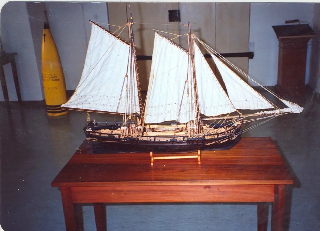
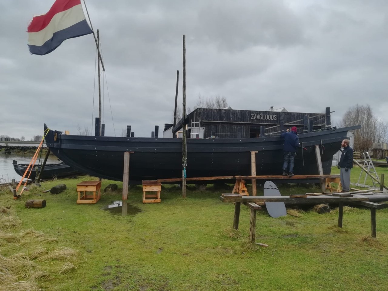
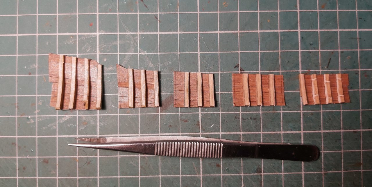
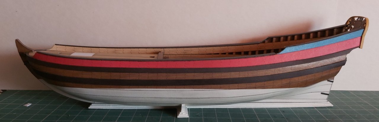
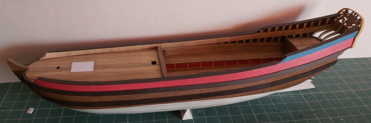
Hi. The hull has been glued with the final planking: I struggled a bit when gluing in the inner planks of bulwark, because there were supposed to be three planks made of separate strips (I like this kind of work 🙂, but they came out so narrow that it didn't make sense. So I tried with just two strips and that also caused a lot of problems. The main reason was gluing the outer sides slightly lower than in the design. So I had to "scrape" the thin inner planks so that they were even with the edge of the side. Secondly, for some reason I didn't get the upper parts right and especially at the stern they spread out a bit. There was nothing left to do but simplify and make it easier: from the inside there is only one strip pretending I considered different color versions, because generally they were "sad" vessels. They played a secondary role of guarding fishing areas or port entrances, so noone invested in paints or copper plates for the underwater part of the hull. They were mostly black from the tar used and... and that's it (see the photo of the model from the Norwegian museum). It's a bit unattractive, so after looking at historic models of various gunboats, I added dirty-grey-red and a bit of lighter wood, more or less in the color of yellow ochre. I don't plan on adding more colors. I also didn't add a different color to the bottom, because in the cold waters of the Arctic Circle, naval shipworms (teredo navalis) weren't a problem. At one time, even Chapman postulated that the copper plates should be removed from Swedish units in the Baltic, because they weren't needed, and it would result in great savings. Norwegian units sailed in even colder waters and, additionally, as a coast guard, they were not expected to participate in pursuits. So any investments were a waste of funds. The rails were made of two layers, because the lower parts were thicker and, let's say, "milled". The higher part and the transom are just single strips. So far (apart from the modification of the interior of the bulwark) everything has come together beautifully. I am pleasantly surprised by the reception of the first videos on YT from the construction of this model. Over 100 subscribers, so you gave me no choice and the next episode from the above stage is already available to watch: Axel Thorsen part 4 (eng subtitles in YT options) Greetings Tomek
- 7 replies
-
- 7
-
-
- Axel Thorsen
- gunboat
- (and 1 more)
-
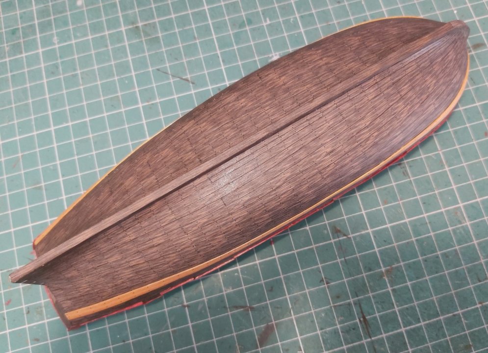
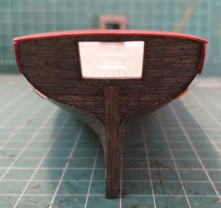
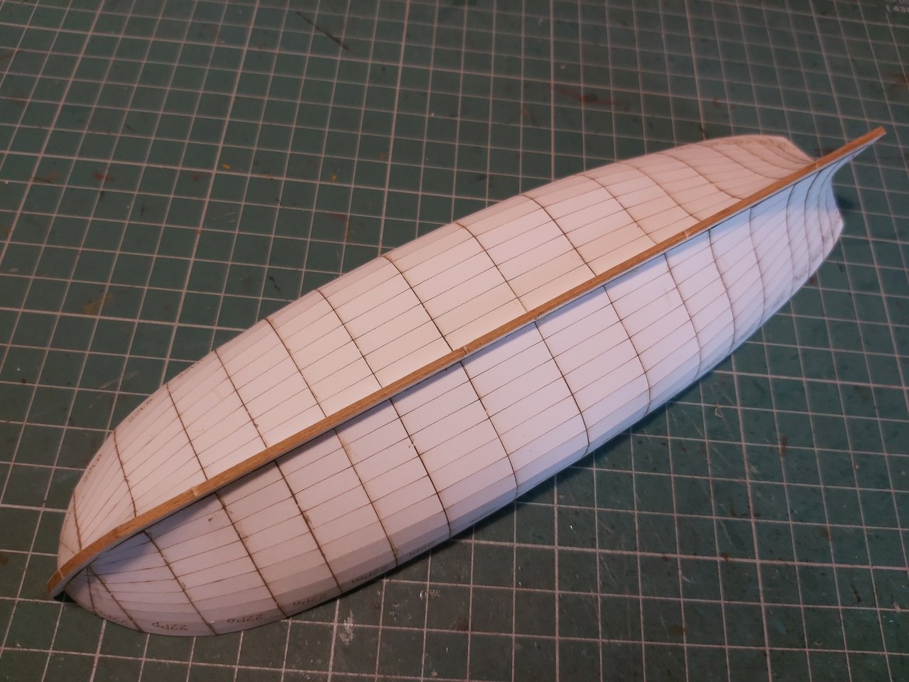
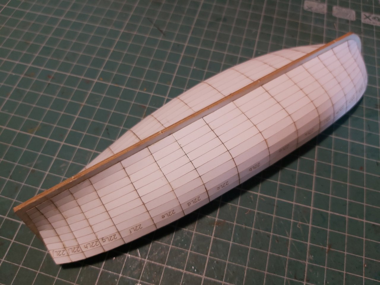
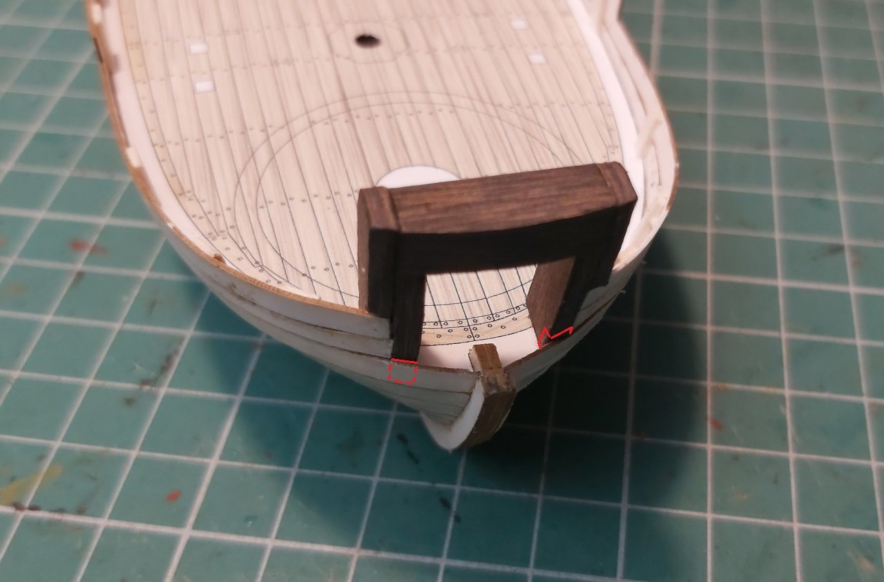
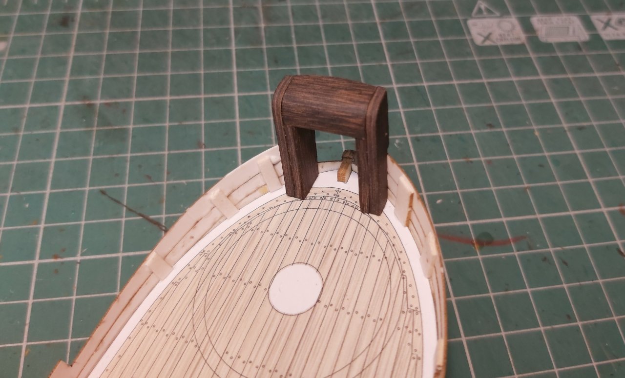
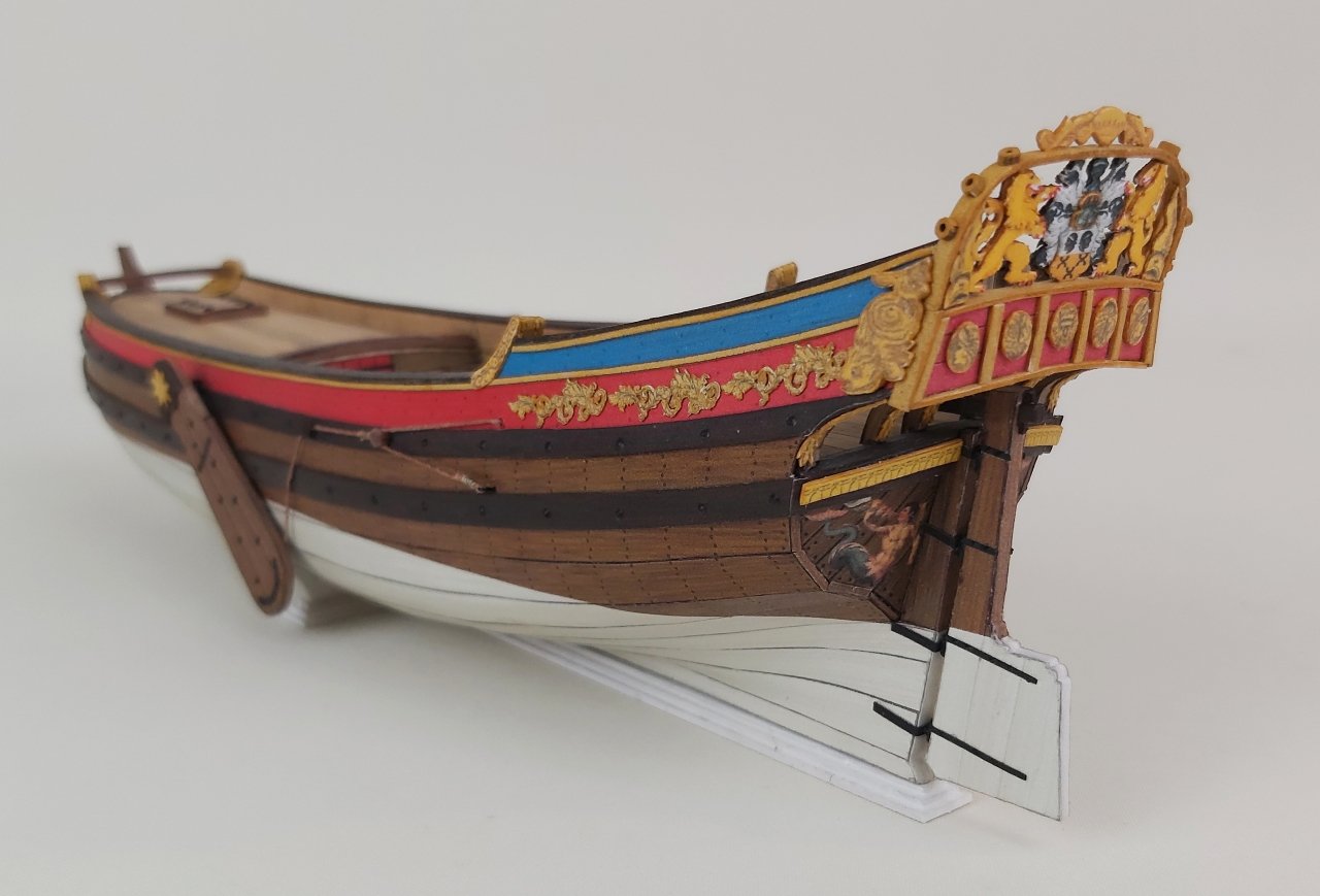
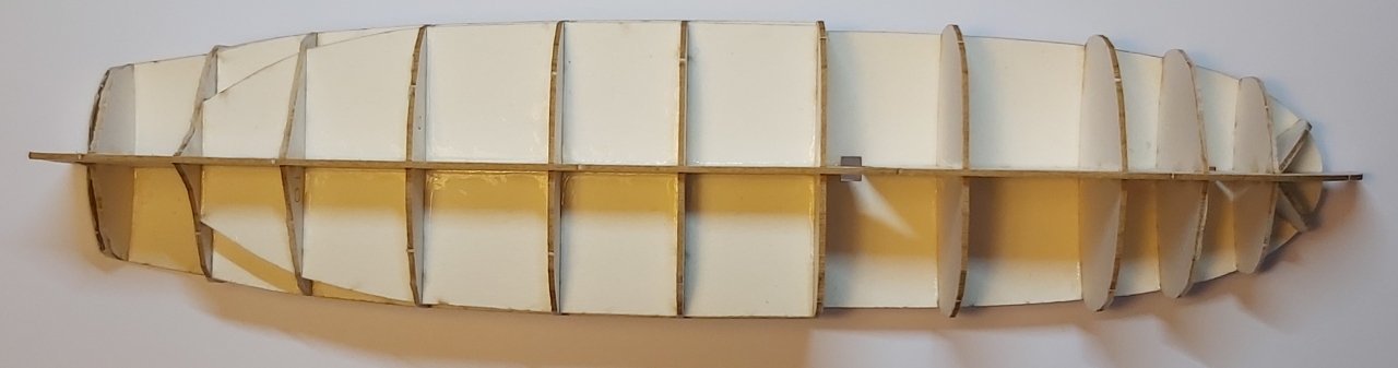
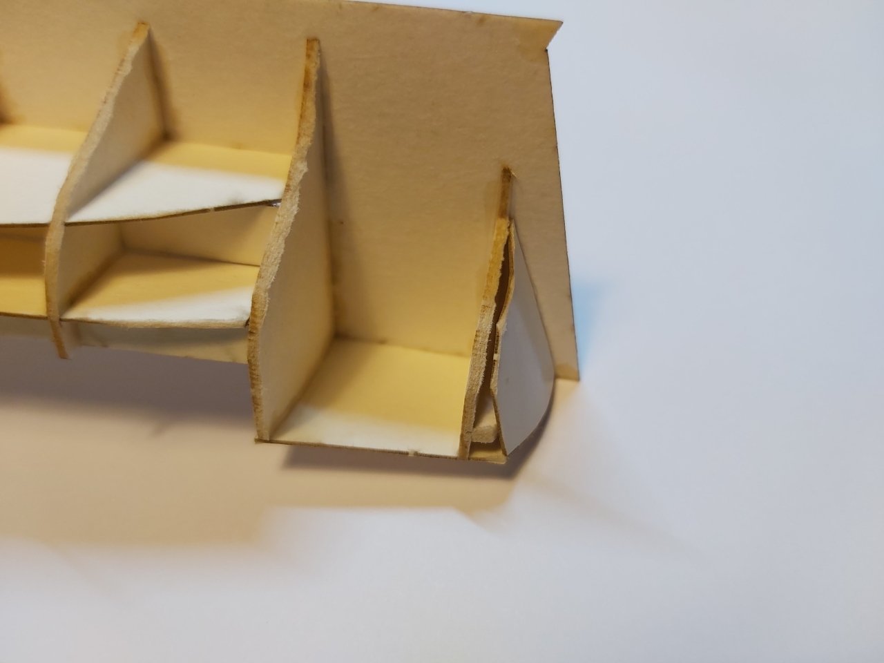
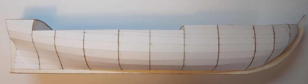
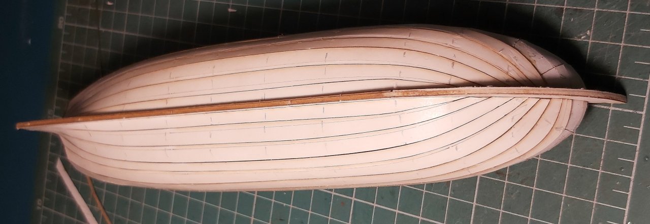
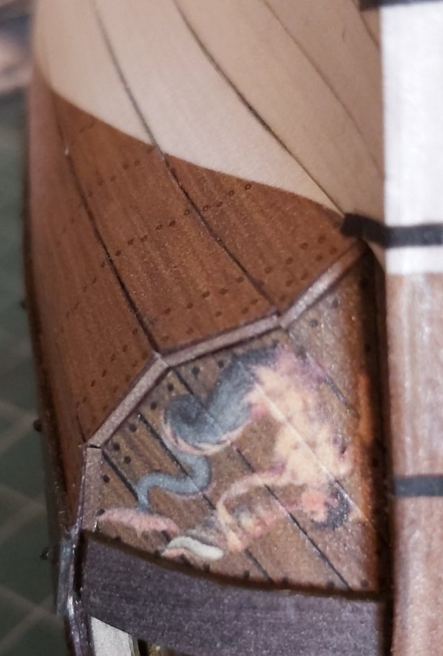
Hello everyone. From the first time I saw this unit, I knew I had to build it someday. And it happened! The gunboat "Axel Thorsen" had its twin "Skjøn Walborg" and both were launched in 1810. Initially, they served as patrol ships, tasked with protecting merchant ships leaving Arkhangelsk from attacks by the British during the Napoleonic Wars. After the Peace of 1815, Norwegian authorities viewed Russian activities in Finnmark in northern Norway with great suspicion, and in 1816 Axel Thorsen was sent north to remove Russian settlers from the area and demolish their buildings. In 1817 and 1818 this role was taken over by Skjøn Walborg. Both ships also participated in a mapping program in the High North. In 1831 and 1832, a cholera epidemic broke out in Arkhangelsk and the aim of both units was to prevent ships sailing from the epidemic area from calling in northern Norway. In 1864, Axel Thorsen participated in the Svalbard expedition organized by Adolf Nordenskiöld, while Skjøn Walborg was used by Graf Walburg-Ziel and Baron von Heuglin on a similar expedition in 1870. Both ships were extensively engaged in seal and walrus hunting in Nova Zemlya. Their lives ended in 1872 when both were crushed in the ice and lost. Few models of this unit have been built so far, I found 3 or 4, but there is an interesting example in a museum in Norway... First of all, of course, there was the frame and the first (transverse) covering. The stringer was made of 2 mm cardboard, as it turned out from the plans, and the frames were made of 1 mm as standard. I must admit that everything was cut with a laser, including the first layer, which is why it has kinks in places of the engraved lines. The next step couldn't be different, so I placed a 0.5 mm cardboard first covering (also laser cut). I'm impressed with my own design, because I didn't have to make any corrections - I cut it out and glued it and everything fit perfectly. To build the bulwarks, it was necessary to make a transom and a wonderful, large gun port on the bow. The transom is so thick that it is made of two 0.5 mm layers and spacer strips between them. To make sure everything fits together (and there are no reference points) I glued these parts together on the hull without gluing it to the deck. After removing it, I adjusted the gunport frames and then glued it permanently to the deck. The bow consists of two thick posts connected by a horizontal beam. The posts need to be filed down and cut with a scalpel to give them the right bevel at the edge of the deck. And then, after some time, I saw my mistake, which was that the third strip of cover (counting from the top) should also "hide" in these posts (showed with red on picture). This will of course be corrected, because the bow gun port is now glued about 0.5 millimeters too far back. And because of this, I immediately had to shorten the last two upper strips of the cover. And now... Why are there so few photos? Because I started making short films showing step by step the test construction of this model. And fascinated with recording, I forgot about the photos :-((( I feel better now, the excitement is gone, so I will also take photos while gluing, I promise. The channel where you can watch the videos is "Seahorse Modele" It is created mainly for cardboard modelers who have not built sailing ships (especially those designed by me with a specific philosophy of making the hull) and wooden shipbuilders who, out of curiosity, try their hand at cardboard. I've found that the biggest challenge is switching to a different material and treating paper and cardboard not like wood. I invite. If you like it, please like, comment and, preferably, subscribe! Whether I will continue making guides depends (understandably) on interest. Regards Tomek
- 7 replies
-
- 7
-
-
- Axel Thorsen
- gunboat
- (and 1 more)
-
The sequence you propose also has the advantage that when gluing the hull planks, you will not damage the bulwarks, which are very unstable if they are not reinforced with planks. Tomek
- 146 replies
-
- 5
-
-
- Speeljacht
- Seahorse
- (and 2 more)
-
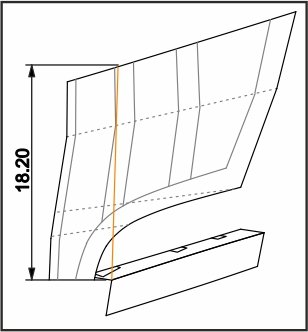
Hi Chris, I think it's not a big problem. As you rightly noticed, this entire area will be invisible both from the outside and inside. Even if not all the posts were glued to the benches, the whole thing would still be reinforced with planks on both sides. I glued these parts in pairs (two per side 29-33 and 34-35), which makes it easier to match. I think Marcel's suggestion is ok to add another plank and then glue/adjust the bulwarks to it. Or you can glue the bulwarks only where possible, and the whole thing will be gradually reinforced with external and internal planks. Just make sure that the stern part of the bulwark does not rise. There should be approximately 18.20 mm from the outer corner of part 25 to the top edge of part 36a, as below (isometric view, not side view). Tomek
- 146 replies
-
- 9
-
-
- Speeljacht
- Seahorse
- (and 2 more)
-
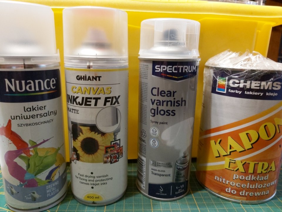
For an average effect, rattle-cans are enough. These are the ones I use and I'm satisfied. Previously, all ambitious cardboard modellers in Poland used a varnish called "Kapon" (nitrocellulose primer for wood, contains xylene (a mixture of isomers) and ethyl acetate), but this was withdrawn for ecological reasons. It was applied with a brush or roller 1-3 times, which turned the paper almost into thin plastic. After building the model, of course, one layer of matte varnish was applied. I don't use an air brush, but apparently it works great, especially with professional modeling chemicals like Tamiya. This method is more precise than with rattle-can.
- 146 replies
-
- 8
-
-
- Speeljacht
- Seahorse
- (and 2 more)
-
A more advanced method is to protect the sheets with a glossy acrylic varnish and then lightly spray the finished model with a matte finish. An additional advantage of gloss varnish is the easy removal of fresh traces of paint used to retouch edges. I use acrylic paints and if I accidentally smear something, I can safely remove the fresh paint with mu finger, the paint will not penetrate the paper. With matte varnish, the paint will not penetrate the paper, but it is more difficult to remove it from a rough, matte surface. Applying a bit of matte varnish on the finished model, in addition to eliminating the gloss of the previous varnish, unifies the "structure" of the surface of various materials (shiny traces of cyanoacrylate glue, shiny metal (wire), painted parts, etc.) Tomek
- 146 replies
-
- 9
-
-
-
- Speeljacht
- Seahorse
- (and 2 more)
-
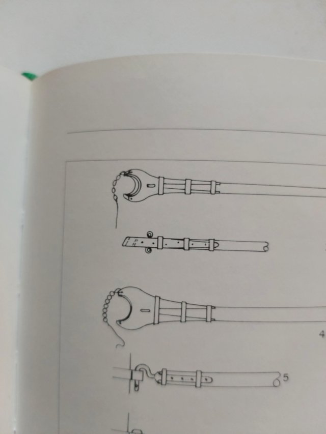
40 is a truss fall (for parrals) Block 2 is attached to the end of the outhaul (33) (I wouldn't call it "clew line"), so it moves forward and backward, as the outhaul is tightened or loosened.
- 63 replies
-
- 1
-
-
- card
- Revenue Cutter
- (and 2 more)
-
Two single about 4 mm, one double 4 mm. Six belaying pins - bottom diameter approx. 0.8 millimeters (Belaying pins) Greetings Tomek
- 146 replies
-
- 7
-
-
- Speeljacht
- Seahorse
- (and 2 more)
-
Blocks: wood, card or 3D resin?
0Seahorse replied to georgeband's topic in Masting, rigging and sails
Thank you @georgeband@ for the review of the blocks. 1. They are not translucent because we use an opaque gray resin with additional pigments to make them dark, "more or less" brown. This makes painting easier (although we do not paint blocks in test models) 2. Visible layers should disappear in the second half of the year, as we plan to buy new printers with much better resolution (the old ones don't want to break down 🙂 3. The size of the sheave is a bit too small (as George pointed out), and this is due to the fact that there are holes on both sides of the block. As "wefalck" rightly pointed out, the hole for the rope should be on one side, but many modelers praise the holes on both sides of the block because it does not require inspection during assembly. You take a block and attach it, and that's it (it will always be OK). 4. The size of the holes themselves, which are proportionally too large especially in smaller blocks, result from the fact that it would be very difficult to pull the rope through a hole of the correct diameter. For a rope with a diameter of 0.2 mm, the hole would have to be 0.22 mm. It's probably not impossible, but extremely difficult. Thank you once again for the positive criticism and we will certainly work on correcting some parameters with the new machines. Greetings Tomasz Weremko -
Seahorse Vistula Barge XVII century - Error correction
0Seahorse replied to modeller_masa's topic in Card and Paper Models
Hi, Thank you for many comments, both regarding the model and general ideas for better publishing of subsequent models. I wouldn't want to go into too much detail about every single detail you wrote about. So roughly the most important shortcomings. 1. In fact, the numbers of several parts have been mixed up and it looks like some are duplicated and others are missing. There are no planks missing, because several modelers in Poland have already built this model and they only just noticed the numbering confusion. Either way, this is my oversight. Below is a translation from the opinion of one of the modelers and a link to his work: "... Unfortunately, the project failed to avoid several errors that are easy to fix. These are: - ribs part 11-40. Some of them are longer than the places marked for gluing them on the bottom of the hull, part 10. They do not need to be trimmed. Additionally, I resigned from part c, so as not to make them too thick. - planks. From what I remember, three of them have incorrect markings on the outside. Planks 48La bow part - the number is duplicated, in practice one of them is 46La. The numbers of one of the outer, stern planks, between 46 and 48, have also been swapped, I matched them based on the inner part..." Szkuta built by T. Król And the second build log with similar notes: Szkuta built by Ryszard 2. When it comes to the instructions and assembly drawings, further shots/details can always be added, so whether in my projects or in cooperation with other designers, we will try to ensure that the instructions are as readable and clear as possible for the modeler . Congratulations on the built model! Greeting Tomek -
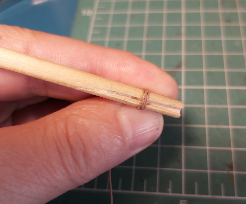
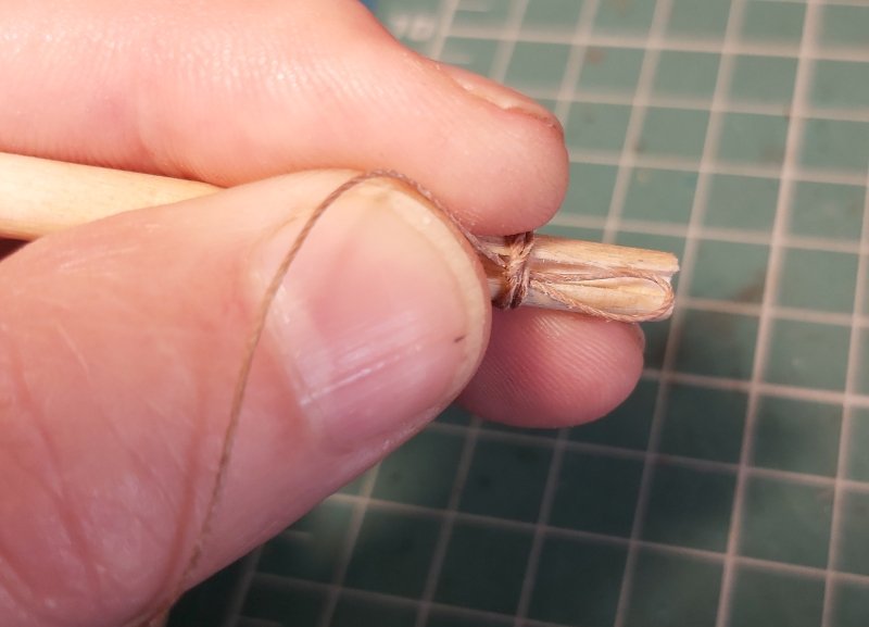
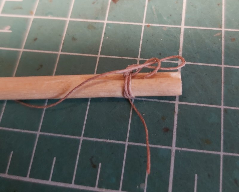
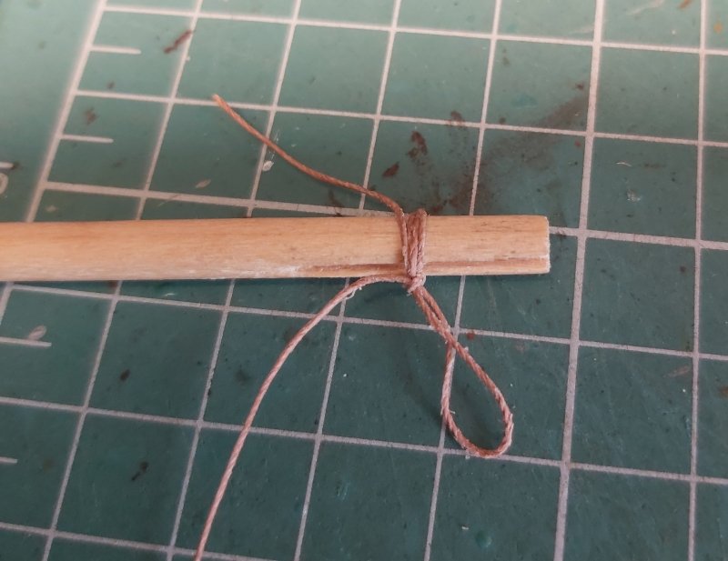
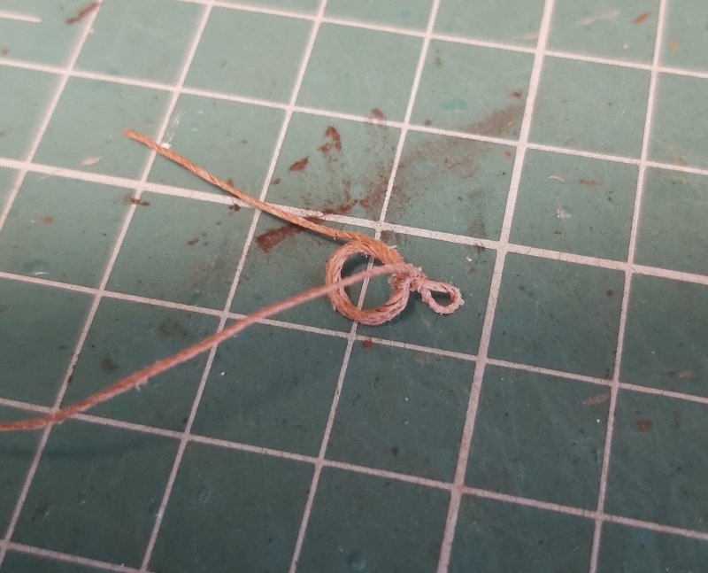
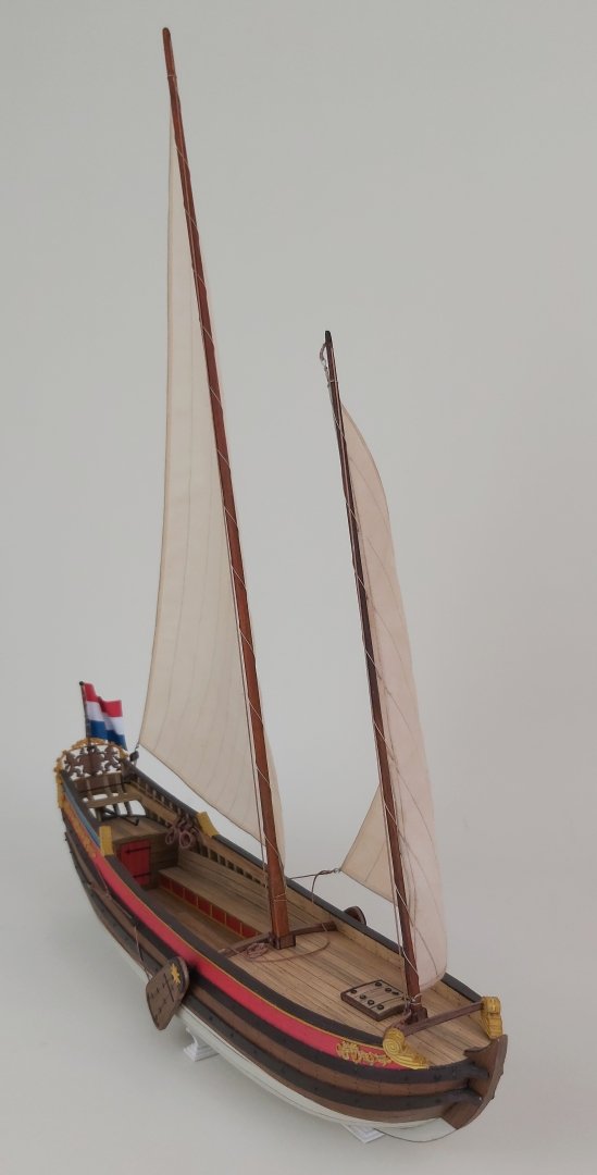
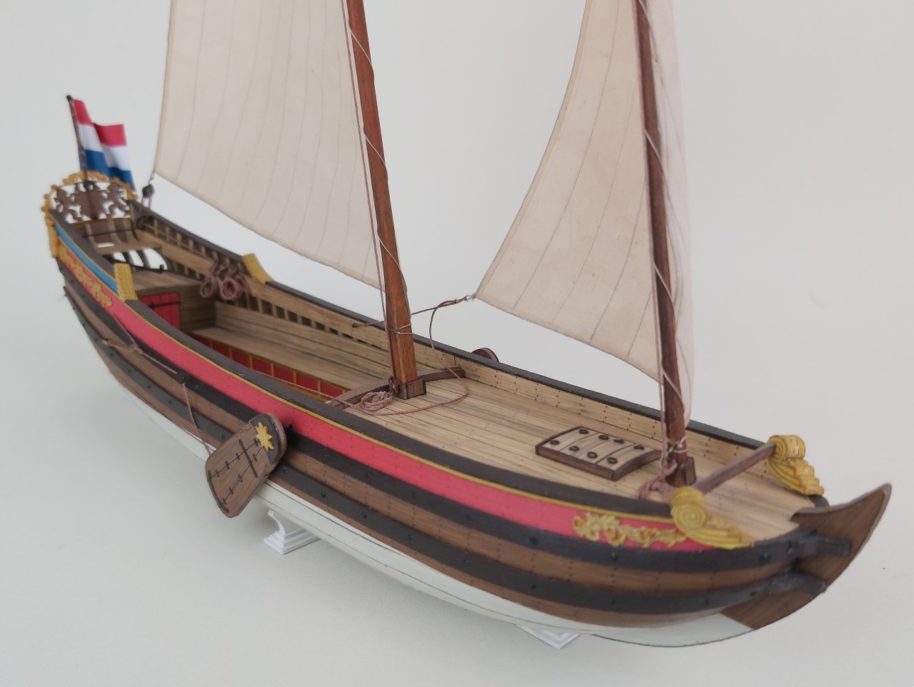
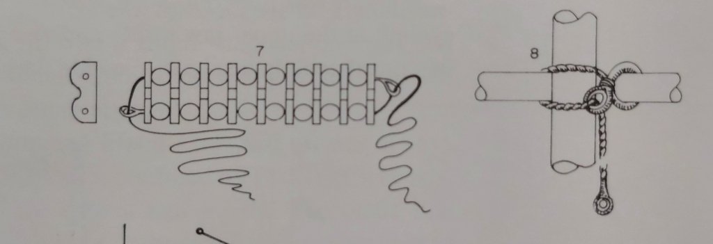
The moment has finally come, "finally", because I made two sails all week long and made a total of 12 of them. Each time something went wrong (stains), I made a mistake (wrong course of the warp and weft), after the third attempt it turned out that I drew the template wrong, the fourth one had stains again, etc. But finally the model is finished. All in all, with such simple rigging there is not much to describe, so maybe I will share an idea (found on YT and simplified) for a different way of making coils of ropes hung on belaying pins. There are, of course, several methods for making and hanging coils, and one of them involves tying them in such a way that there is a single loop at the top and only this loop is attached to the belaying pin. The original video is here: How to make coils. Taking into account that the scale is smaller, I used a 6mm round dowel in which I quickly cut a groove. 1. I braided dowel 4 times 2. I passed one loop 3. I put the second loop into the first loop 4. I tightened everything together 5. the size of the loop can be adjusted with the free end of the rope I don't know how this method will work at 1:100, but at 1:50 it's certainly a good idea. And now a few pictures: Greetings Tomek
- 9 replies
-
- 13
-
-
-
- Speeljacht
- card
- (and 1 more)
-
@ccoyle Chris, I am preparing instructions and typesetting for the printing house. If I finish this week, next week... we have two holidays and half of Poland takes additional holidays to have... 9 days off. But the work will certainly go to the printing house next week. It would be safe to say by mid-May. Tomek
- 9 replies
-
- 5
-
-
- Speeljacht
- card
- (and 1 more)
-
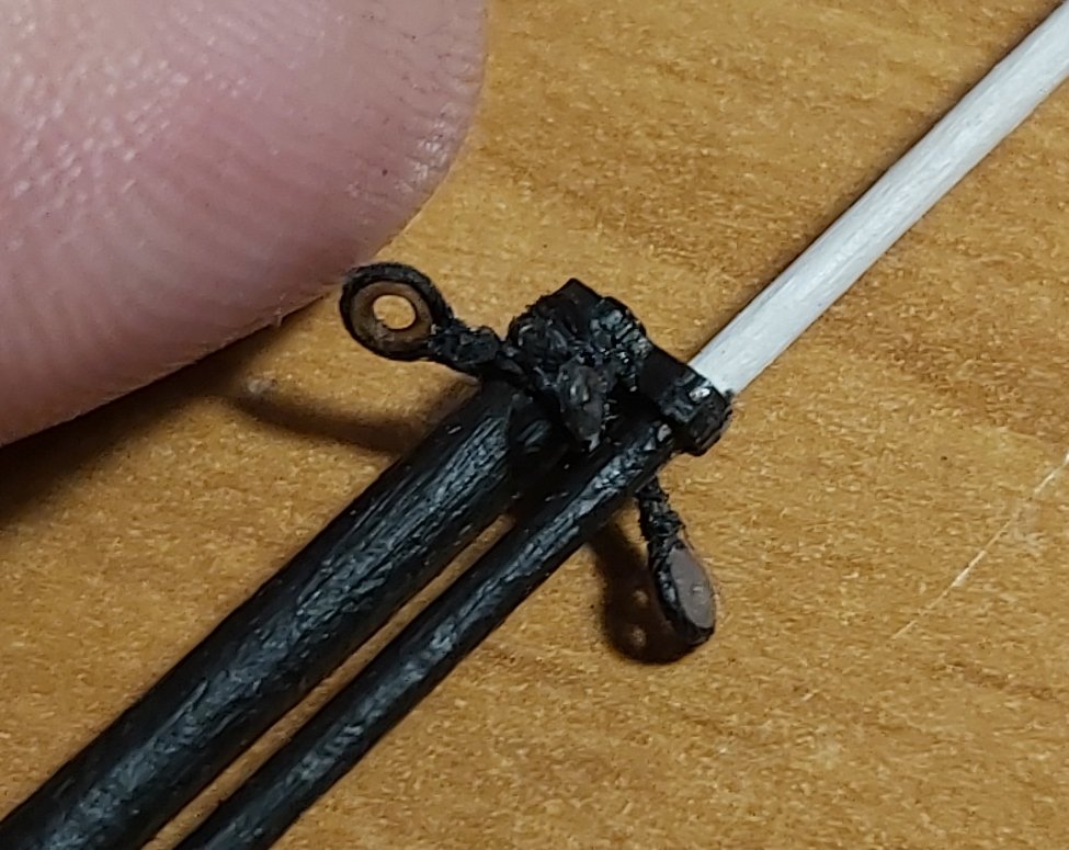
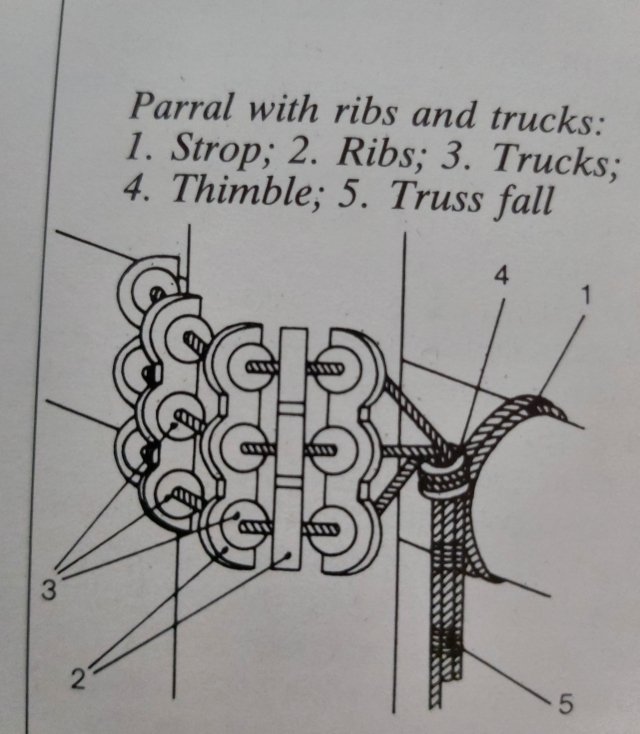
Good job! I tie the thimbles with thread or rope around them, but before seizing, I secure the thread around the thimble with a minimal amount of CA glue, applied with the tip of the needle. As for parrals, I think these beads are called "trucks", at least that's how I read Modefeld's drawings. ("Historic Ship Models" by W. Modfeld) Boom and gaff probably definitely had these "beads". In the case of yards, it could be an ordinary truss pendant (i.e. just a rope). ("The Global Schooner" by K. H. Marquardt) The suggestion to use wire insulation is simply an imitation of these beads, as they are so small that making them by hand without precise tools may be very difficult. Best wishes Tomek
- 63 replies
-
- 3
-
-
- card
- Revenue Cutter
- (and 2 more)
-
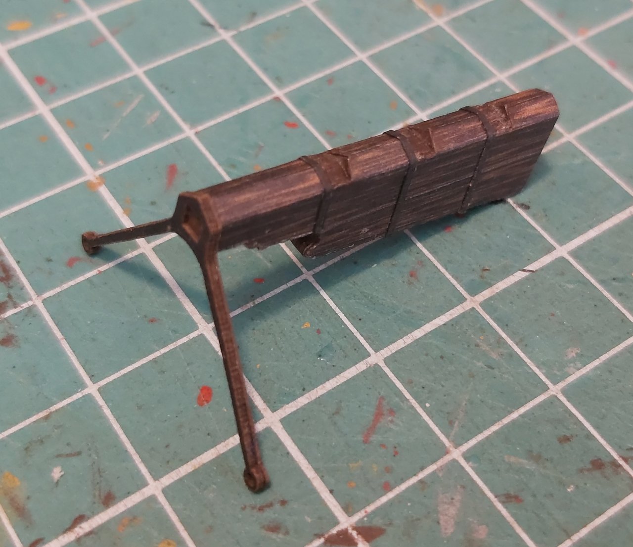
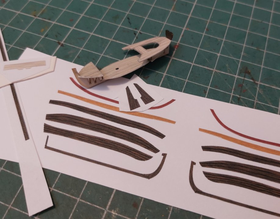
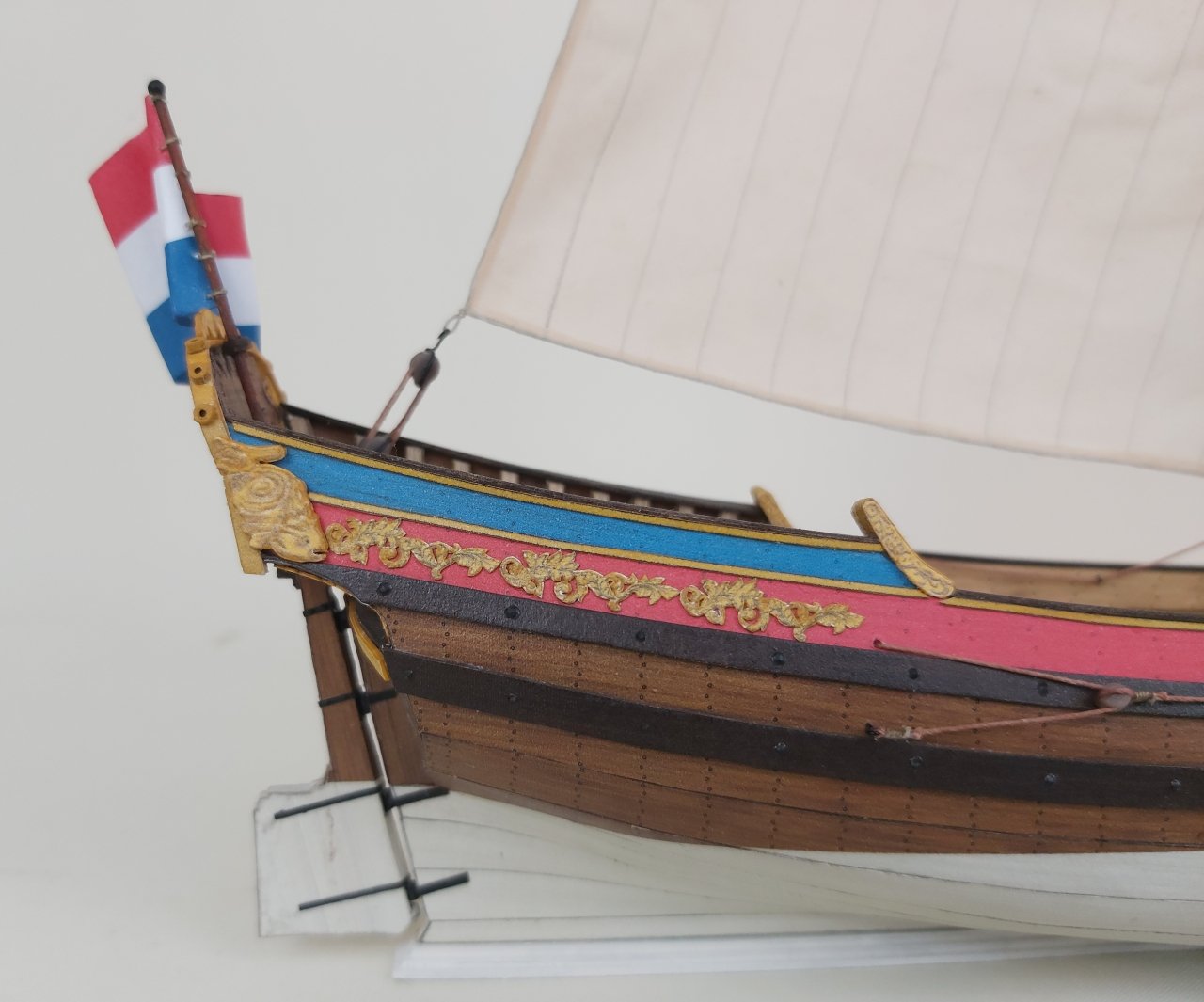
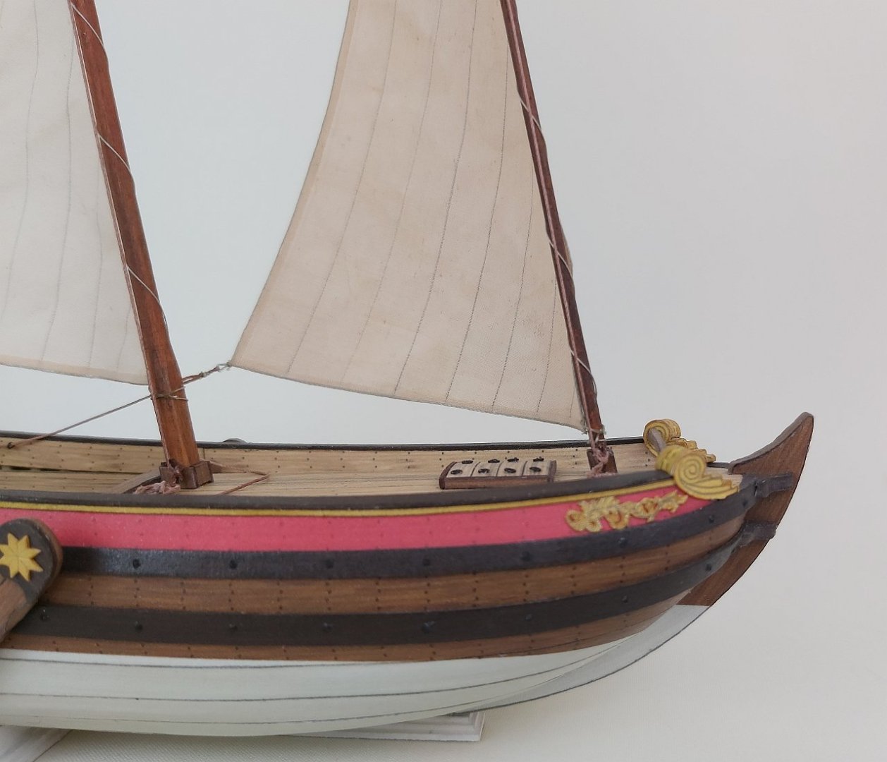
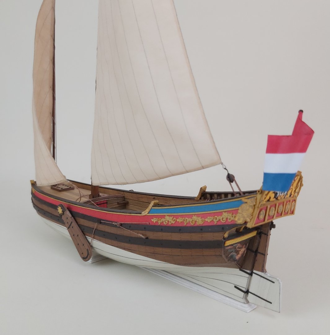
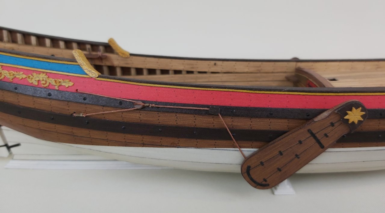
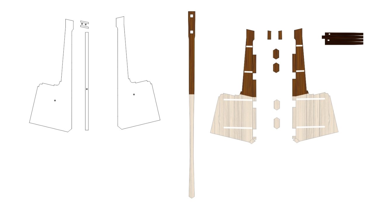
It took a long time to finish the hull, but it can finally be presented. In accordance with period drawings, I applied thick nails (glue and paint) on the wales, and attached two pairs of reinforcements to the stem. All the finishing touches and modest decorations appeared. Initially, I thought about cutting them with a laser, but it would require some plasticizing (e.g. with glue) and painting - which means a lot of work and time. So I cut out several copies by hand with a sharp scalpel and glued them to the sides. The decorative ends of the railings are simple bottomless "boxes" that I used to mask the ends of the edges of the railing. In the stern part there are belaying pins printed in resin , a bench and a rod on which the sheet of the second sail moved. And a few little things at the stern. All decorations are "conventional", i.e. you can make others according to your own intuition and skills. Leeboards, characteristic for coastal units that moved in shallow waters, according to the plans, had semi-circular indentations - after gluing such a part, I gently cut out these indentations with a scalpel, corrected them with a file and covered the whole thing with strips. They were hung with an eye on a hook coming from the side. They were lifted by ropes, which is clearly visible in the photos. A few more words about the rudder blade, which unfortunately I don't have any photos of. A simplified version would consist of layers of cardboard and that's it. Usually, however, the rudder blade was thicker at the front edge and thinner at the rear. That's what I did: the side layers of 0.5 mm cardboard are glued together at the back, and an additional narrow strip of cardboard is glued between at the front. This can be seen on the masking strips. The front edge (where hinges are) was not perpendicular, but ended at an angle - the glued side parts in the color have appropriate protrusions at the front, which, glued together, create a triangular ending. The recesses for the hinge axles are, of course, masked with another small strips. The thicker upper part of the stern blade, where the tiller is mounted, was created by appropriate shaping and simply gluing thicker cardboard between. For imaginative modelers, instead of the missing photos, I am posting a scan of the parts. And that's all. Regards Tomek
- 9 replies
-
- 13
-
-
-
- Speeljacht
- card
- (and 1 more)
-
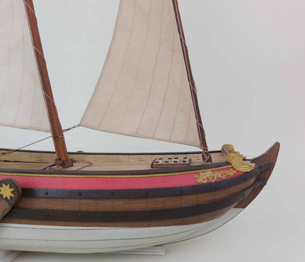
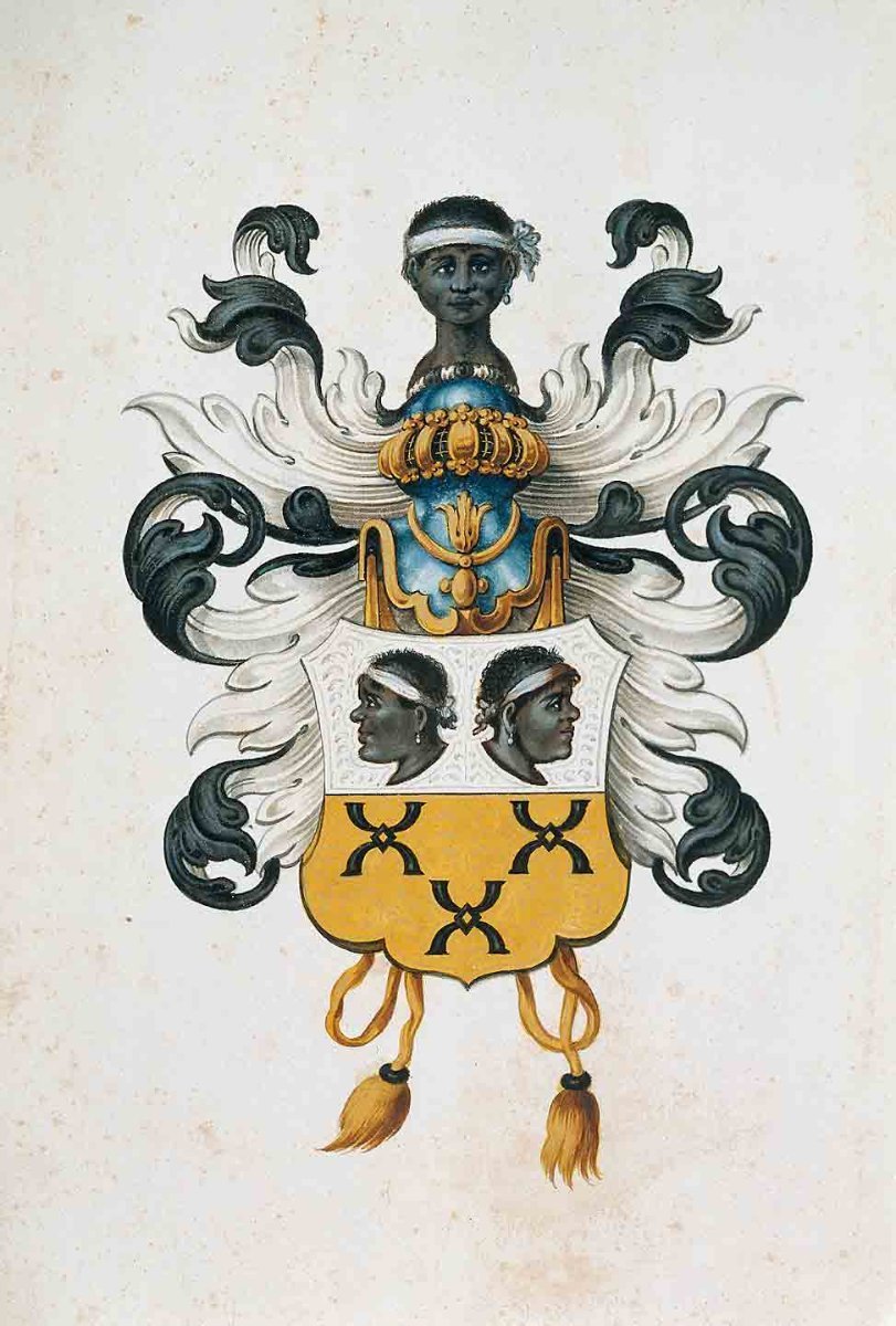
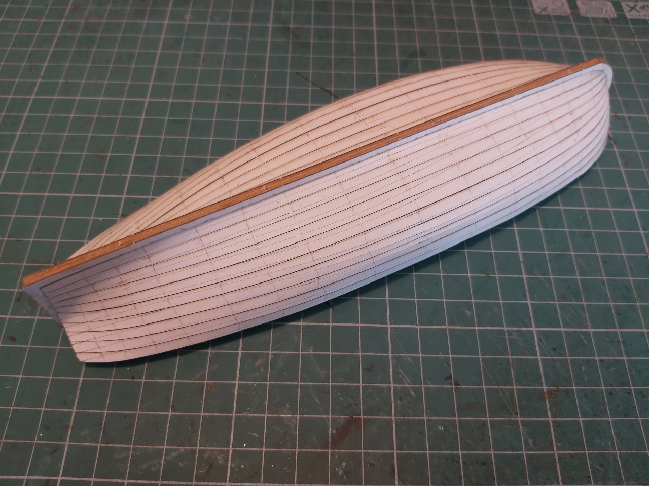
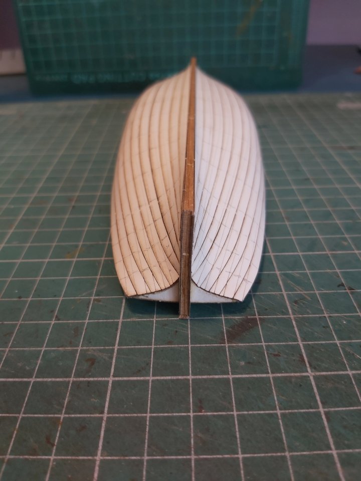
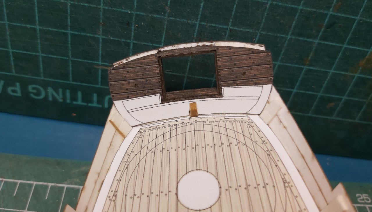
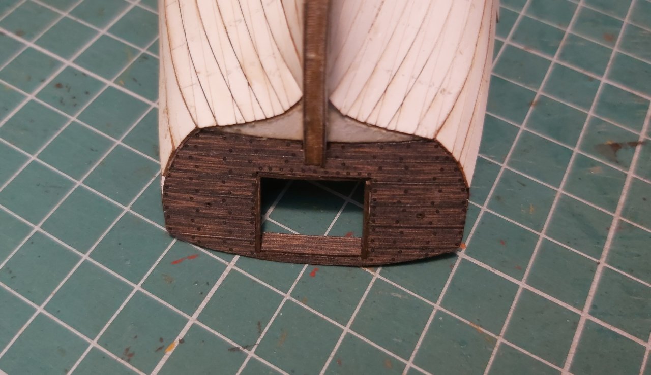
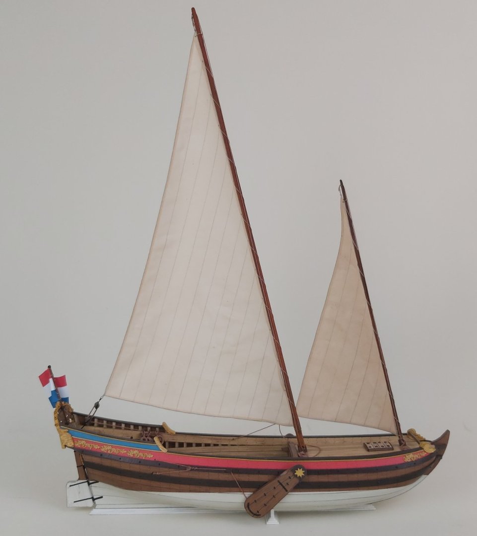
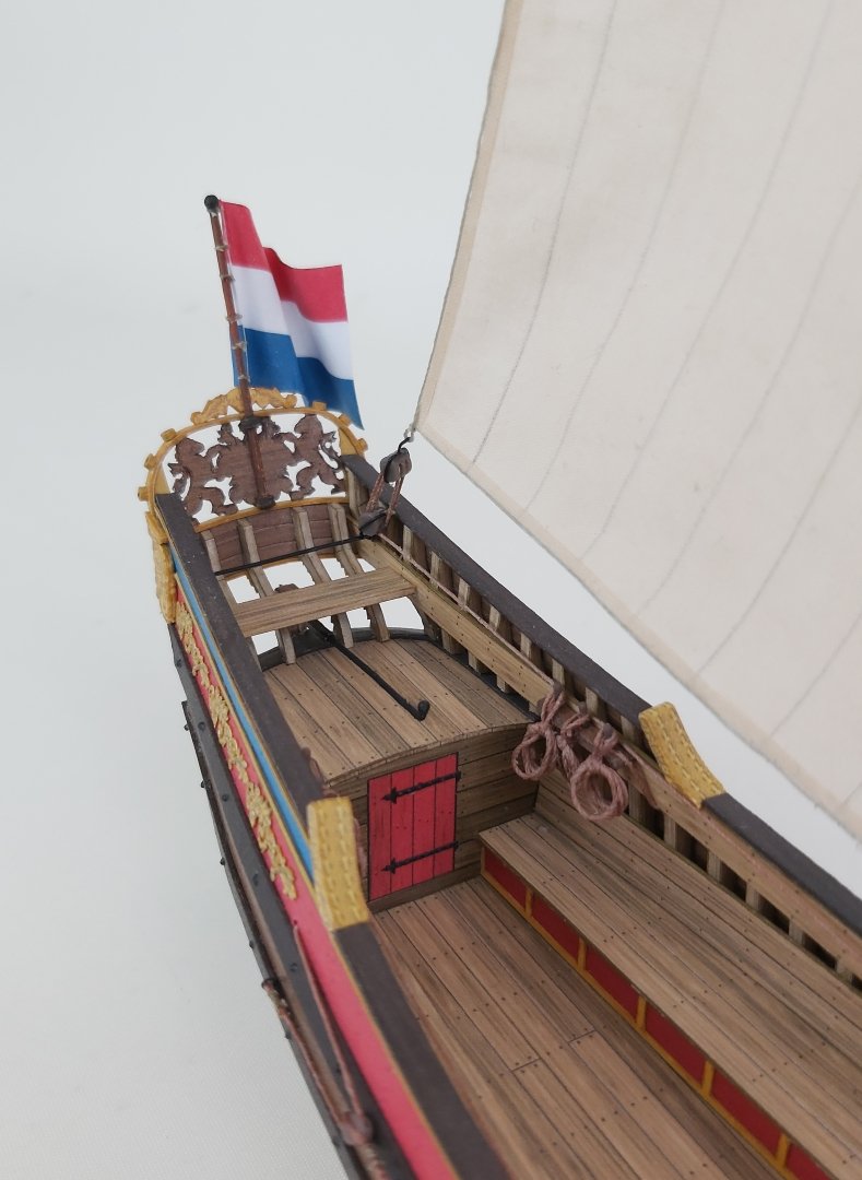
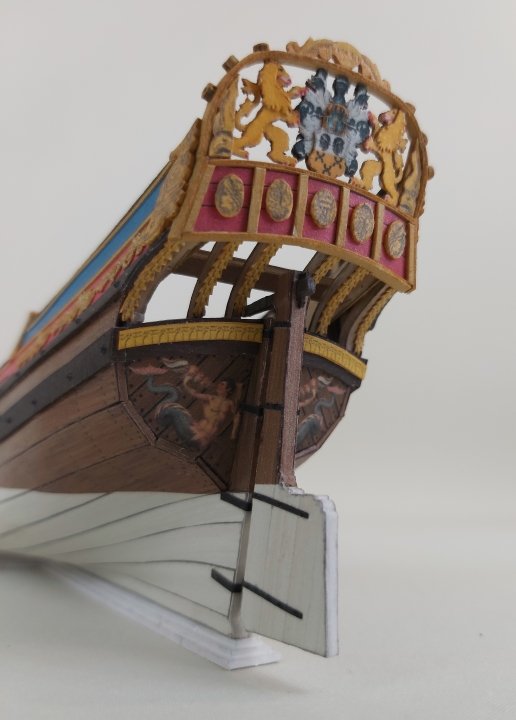
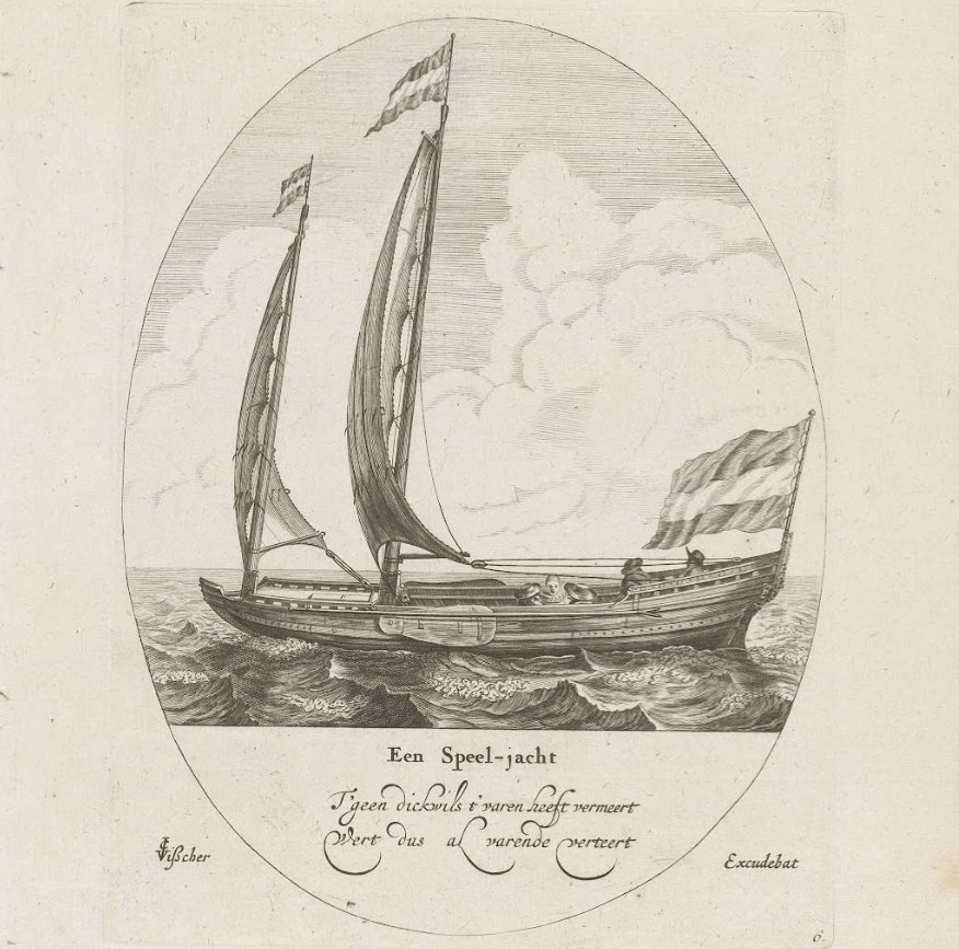
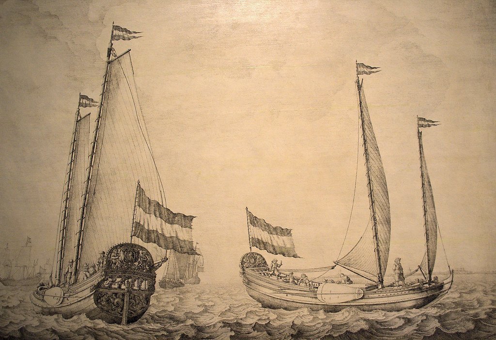
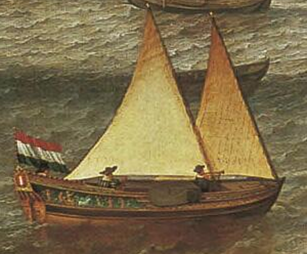
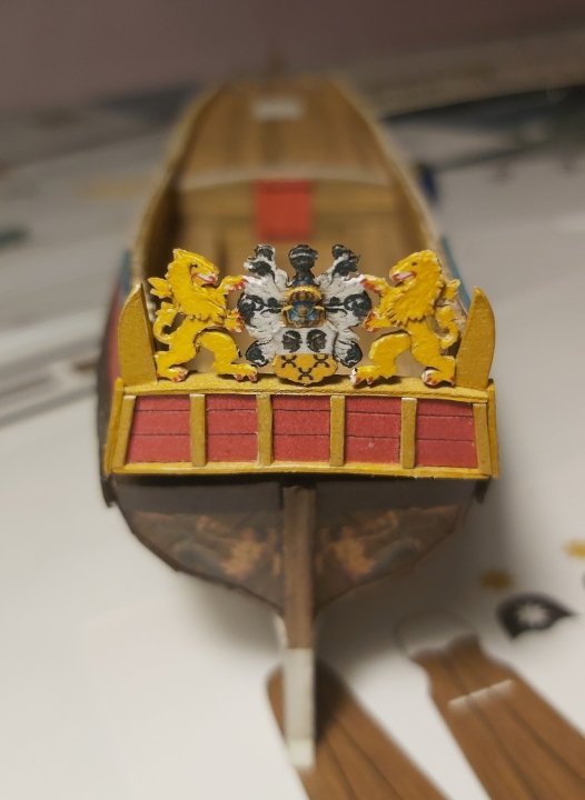
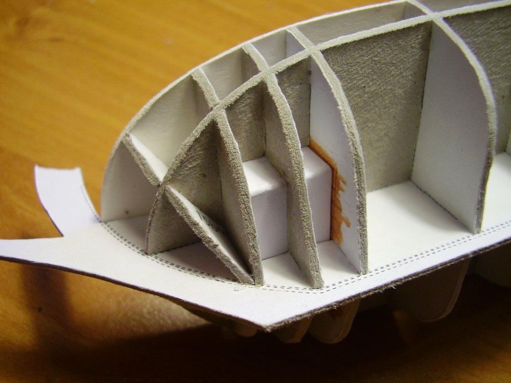
Hello colleagues Many modeler friends said to me that it would be nice to assemble a cardboard sailing ship, but rigging is generally too difficult. Therefore, a few years ago I asked Ab Hoving for an idea for a simple model with the simplest possible rigging, and I didn't have to wait long (2-3 hours) when a precise and immediately three-dimensional design of a "recreational yacht" appeared on my computer. ", i.e. "Speeljacht". This design is very similar to the commercially available plans drawn by Cor Emke. [url]https://www.modelbouwtekeningen.nl/nvm-1006017-speeljacht-volgens-nicolaas-witsen-167.html[/url] Recreation on the water was probably not an invention of the Dutch, because in the tomb of Tutankhamun an image of the pharaoh fishing on the Nile was found, which can be considered entertainment on the water. However, until the 17th century, sailing ships of various types fulfilled basically only commercial and war functions or were used for work, such as fishing. It was only when the trade in Asia enabled merchants to build great fortunes that yachts for entertainment appeared. Maybe it was then that "yachting" appeared as a way of spending time with family, friends or for business purposes. Not only did people relax by sailing for pleasure, but such expeditions were accompanied by delicious feasts, including plenty of drinks. Nicolaes Witsen even mentions a "beer house" under the aft deck. In addition to romantic trips, owning such a yacht meant prestige and/or wealth - a bit like modern billionaires and oligarchs. The decorations were chic, but not flashy. The Netherlands was a Calvinist country, so one had to be modest. There was usually a family coat of arms on the stern. A similar model was developed in wood by Kalderstock. And for the inquisitive and curious: the Clean2Anywhere Foundation has been experimentally recycling plastic for several years, building replicas of small historical yachts from it, including this speel yacht. Link to one of the videos where you can see the construction of a speel yacht: [url]https://www.youtube.com/watch?v=eqrIHFulcZU&t=3s[/url] And how is my construction going? So quick and easy that I didn't take many photos, especially obvious stages like frame frames,... ...or "first - false planking" The retouched cardboard edges of decks has always "disgusted" me, so I experimented a bit and glued narrow strips on the visible edges, imitating the face of the boards. The stripe is 0.7 mm, my hand trembled a bit and it didn't turn out perfect, but I think it's a very good idea for the future. Since masking the edges like this has a future, I went ahead and played with the edges of the planks at the stern. There is also something to complain about, but that's my fault - I liked the idea itself. A large number of visible frames required tedious gluing and retouching, and initially I planned to glue them to the hull first and then continue covering them with the planks. Fortunately, before I started committing such stupidity, I changed my concept and built this component separately, finally gluing the finished one to the model. In total, in four stages: 2 amidships and 2 aft. The last layer of planks (in color) went very well, and of course the corrections were made on the edges that are covered with wales. This is how it turned out: Modest decorations (as I wrote at the beginning) will only be made of cardboard (no resin), so that the model is fully paper as standard. It was necessary to choose the coat of arms of some noble family. The final choice fell on the van Loon family, also because their "palace" still houses a popular museum.([url]https://www.museumvanloon.nl[/url]) That's it for now, only decorations, leeboards and very simple rigging remain. Regards Tomek


- 9 replies
-
- 17
-
-
-
- Speeljacht
- card
- (and 1 more)
-
I don't know exactly how Bumażnoje Modelirowanie currently works. I heard that they print in Poland and the current internet address is probably/maybe/perhaps/not sure https://papermodeling.net/index.php?route=information/information&information_id=4. Many stores in Poland (Orlik, WAK, GPM) have their models, so you can alternatively look here.
-
Hello Jeff You perfectly interpreted the markings on the rigging drawings (bloks, cleats, eyebolts). It's exactly as you marked a-b-c. The same applies to attaching blocks to masts. That's exactly what I meant. And you also read the jib boom shift correctly, although of course these all solutions is only my suggestion based on the sources I had at my disposal. Tomek
- 63 replies
-
- 2
-
-
-
- card
- Revenue Cutter
- (and 2 more)
-
Hello Jeff Somehow I missed the fact that you started building this model and didn't suggest a few important things ahead of time. But I'm glad you reached this stage of construction and "conquered" the hull. In cardboard models of sailing ships, the hull is the most critical element of the structure - you cannot use sandpaper to correct something or to narrow the plank by 0.2 mm. What would certainly make construction easier at the very beginning is grinding the frames at appropriate angles, just like when building from wood. I take this into account in all my designs (this hull was not designed by me, but it always works). Of course, the sanding itself should be gentle. If there is no grinding, subsequent layers (parts) become too short. Below is a photo of the frames of different model polished so that all "transitions" are smooth. If a plank (from the last colored layer) is too short, you can glue them a few centimeters at a time and gradually "stretch" the paper using water-based glue (this type of glue softens the paper and changes its dimensions). Of course, such stretching must be done carefully to ensure just don't tear it apart. I regret that I did not present the construction of the model on this forum, which would be helpful for you. If you need more pictures, there are some presentations on Polish cardboard model forums. I will be watching your build with interest. Tomek
- 63 replies
-
- 8
-
-
- card
- Revenue Cutter
- (and 2 more)
-
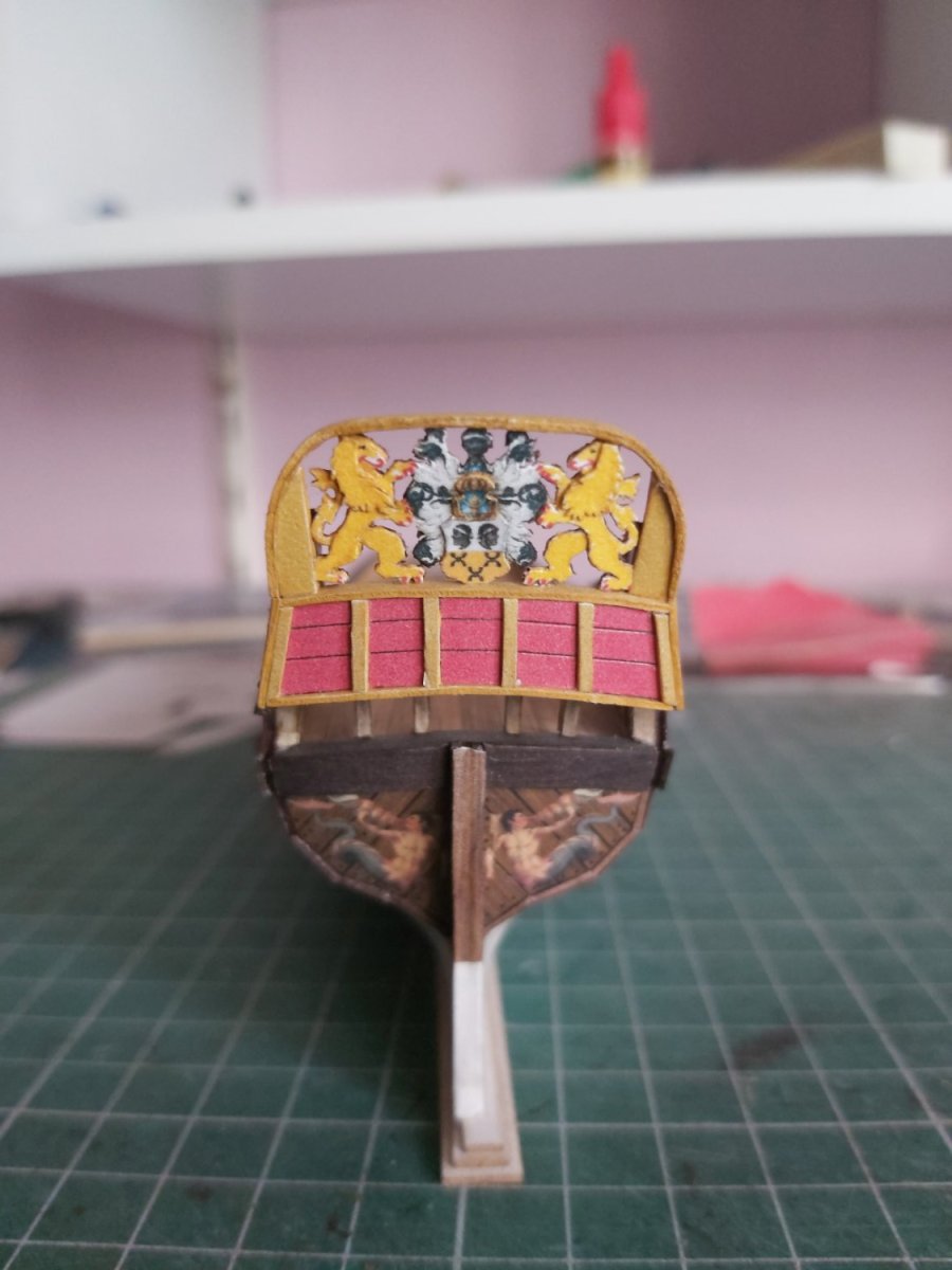
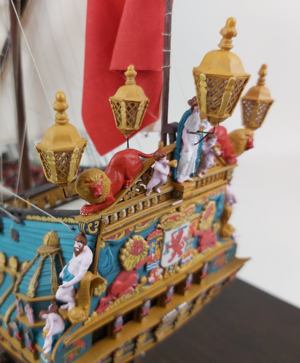
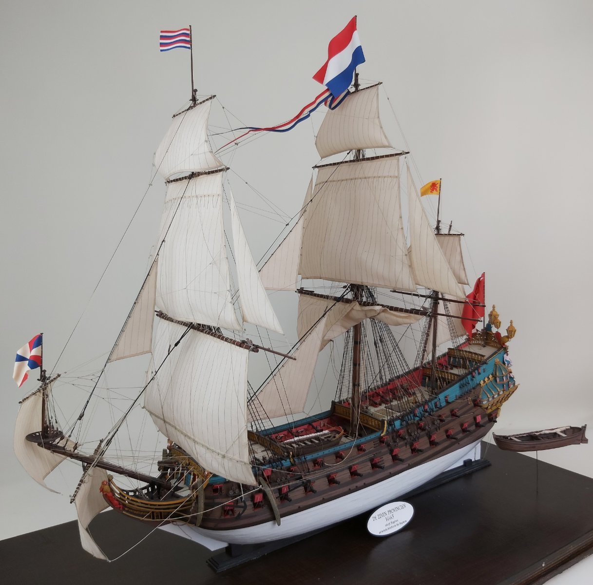
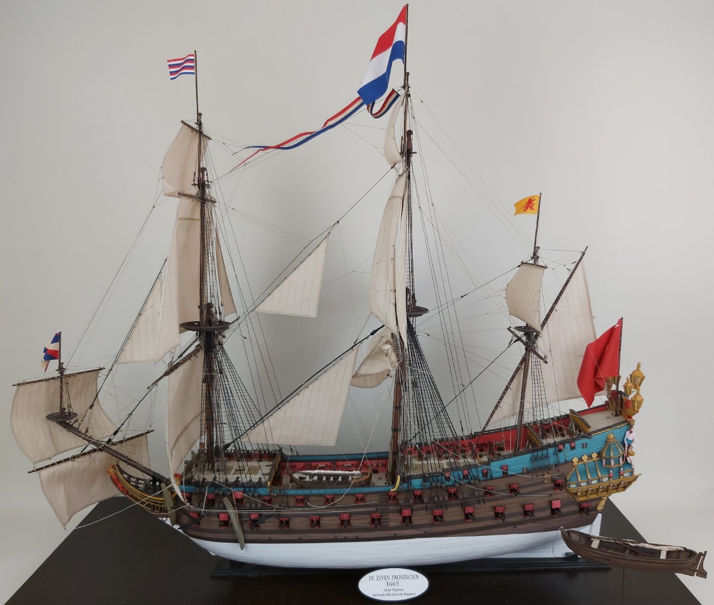
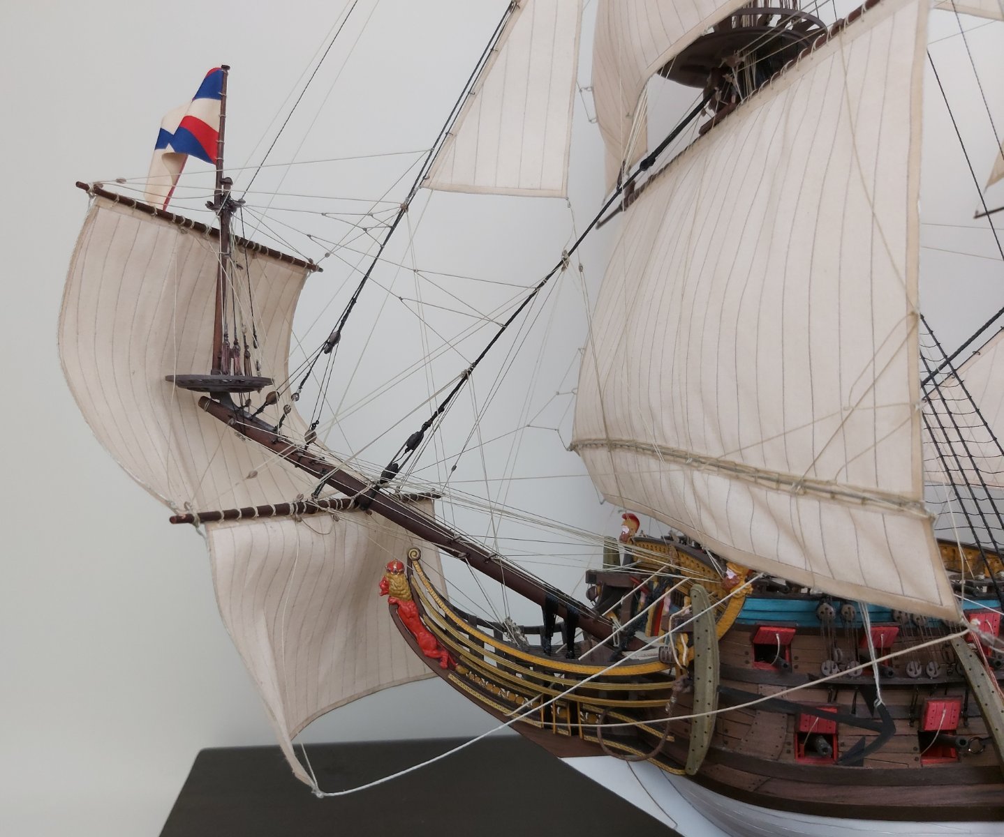
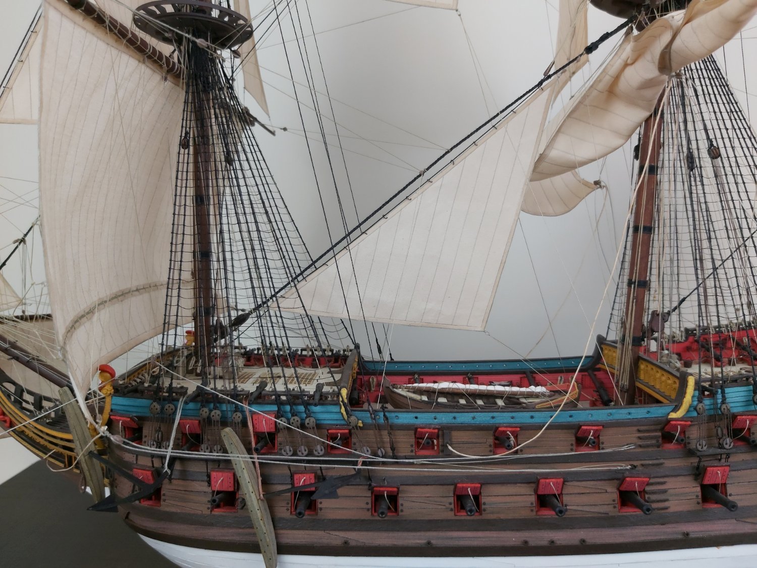
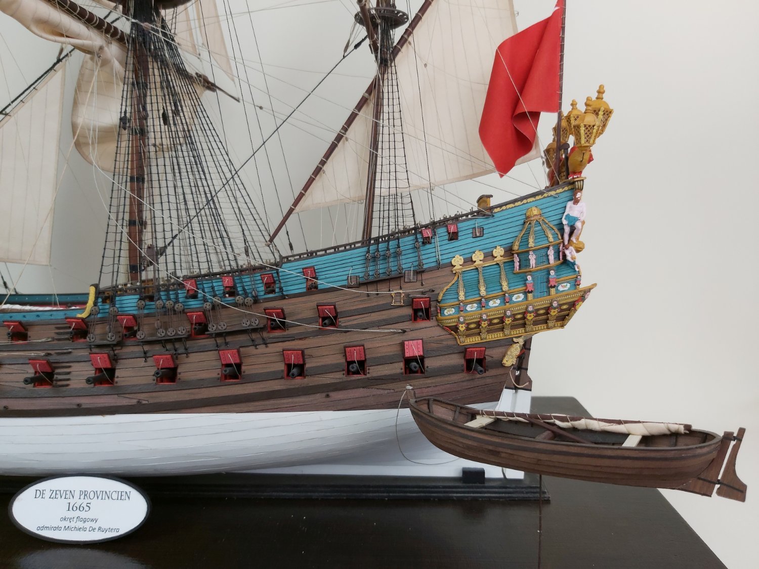
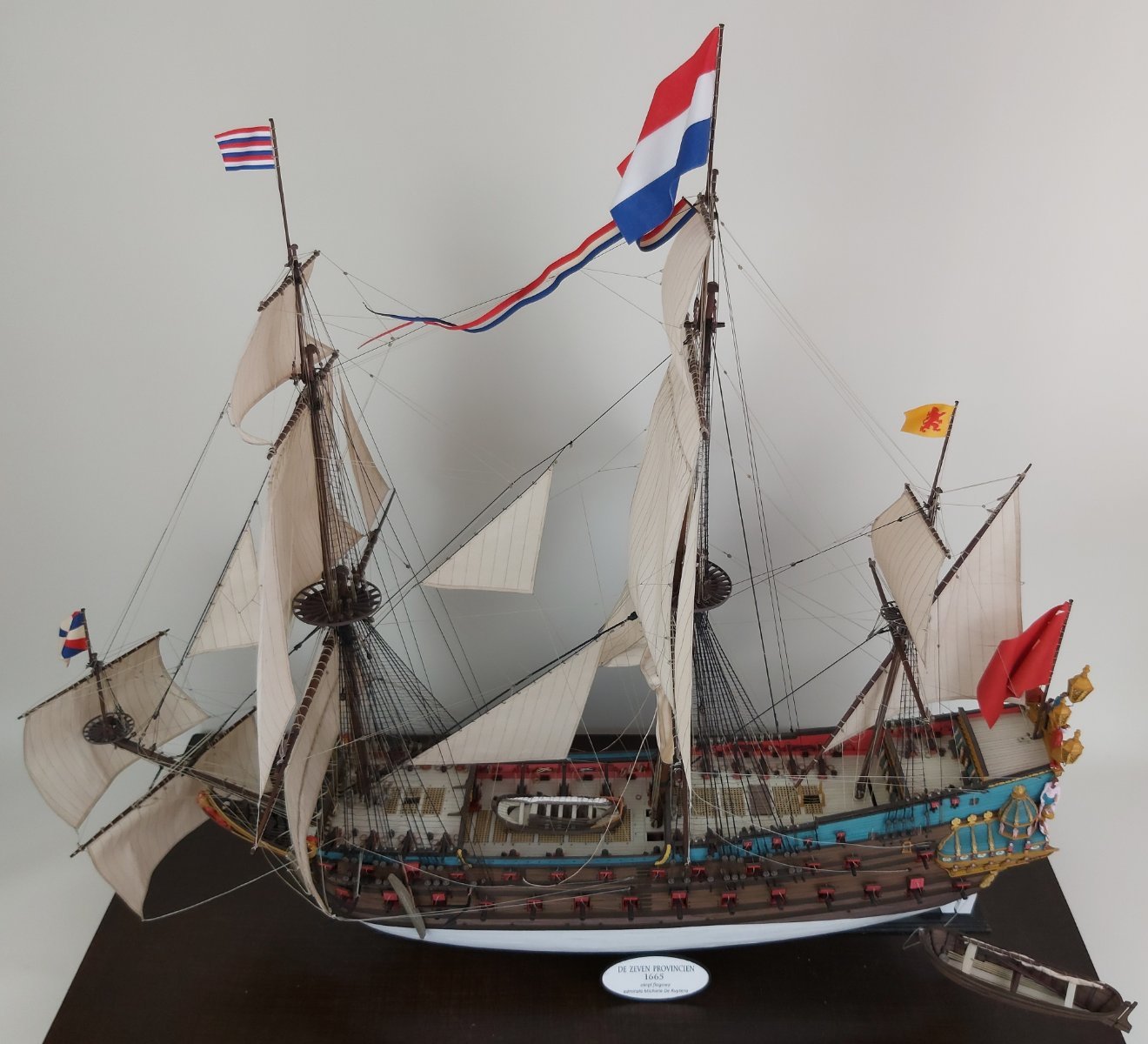
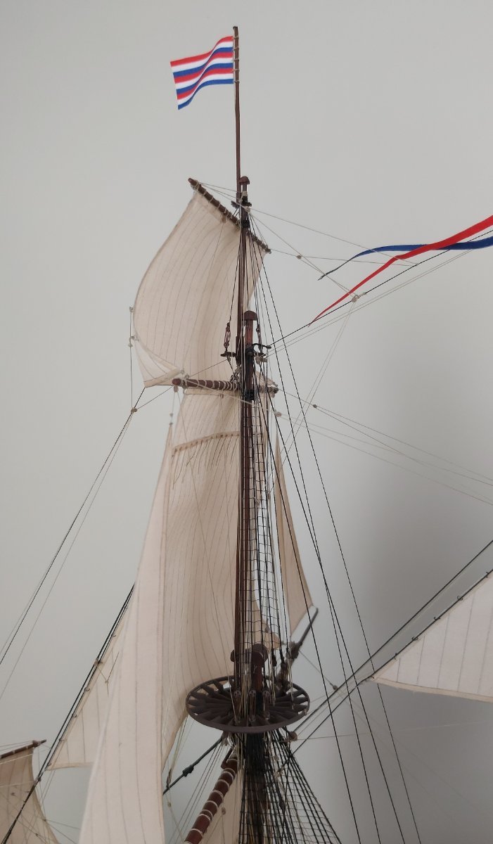
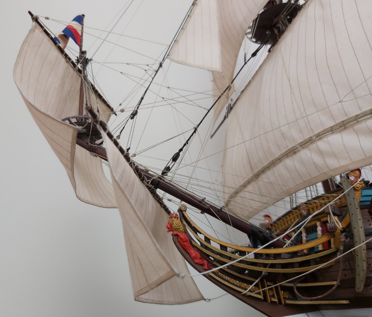
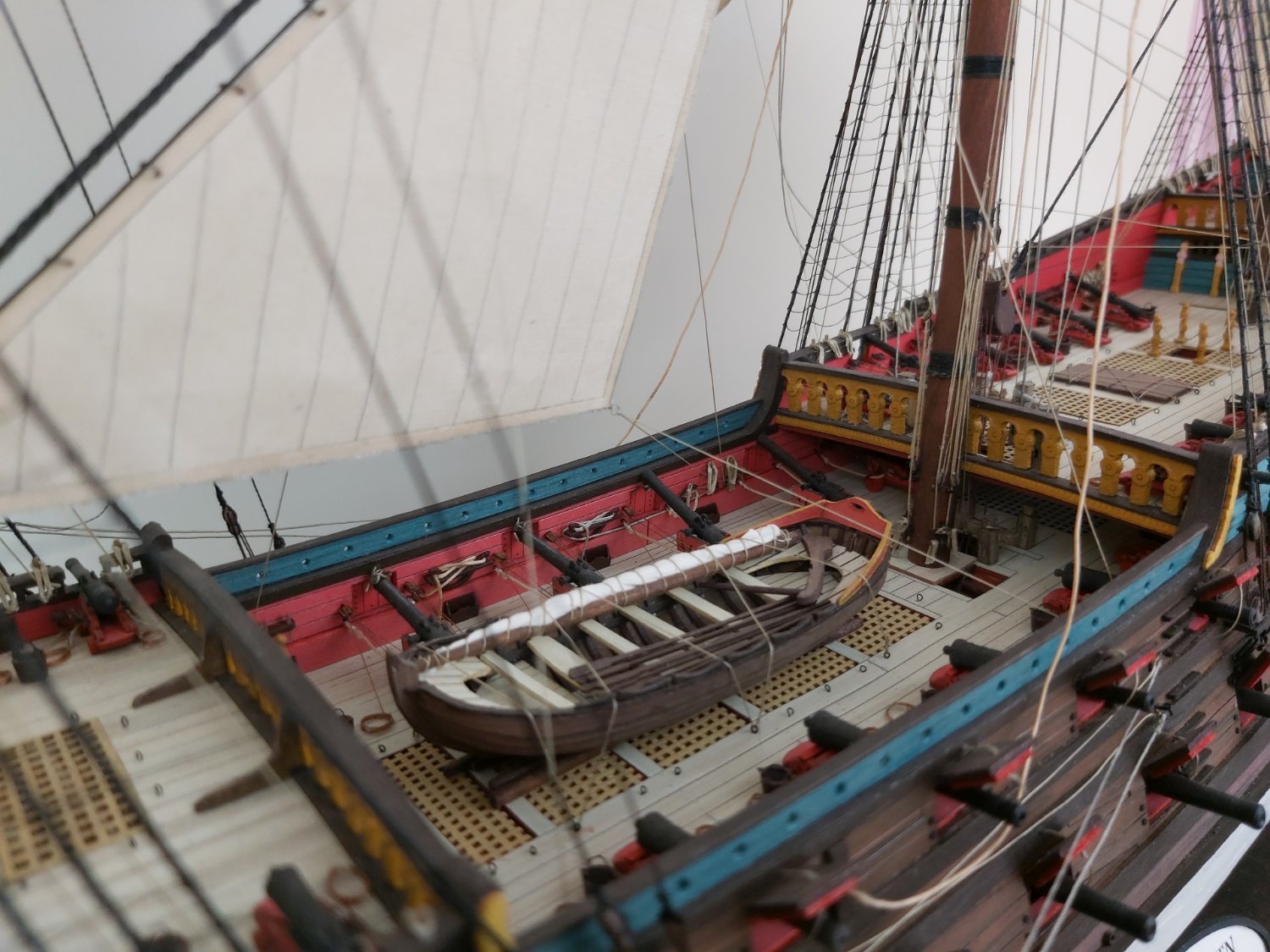
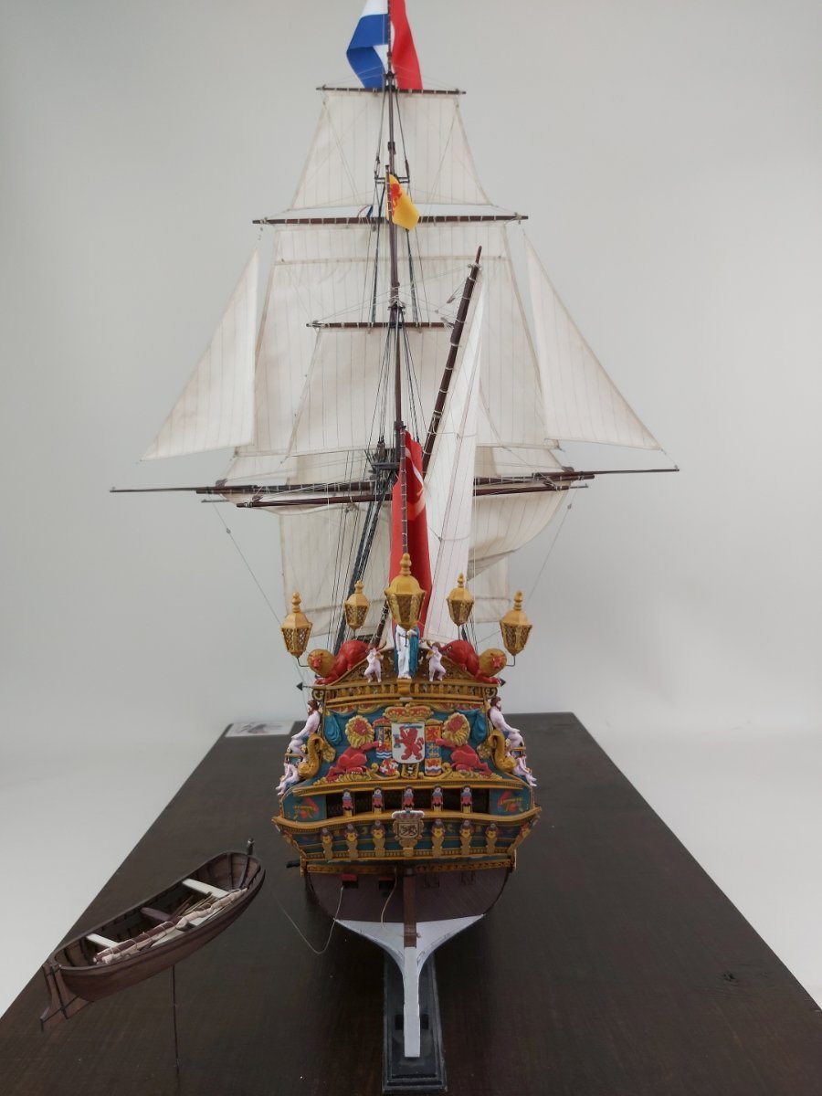
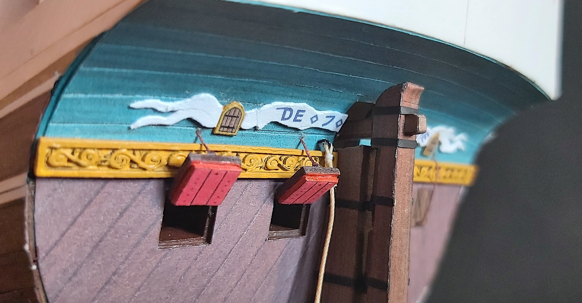
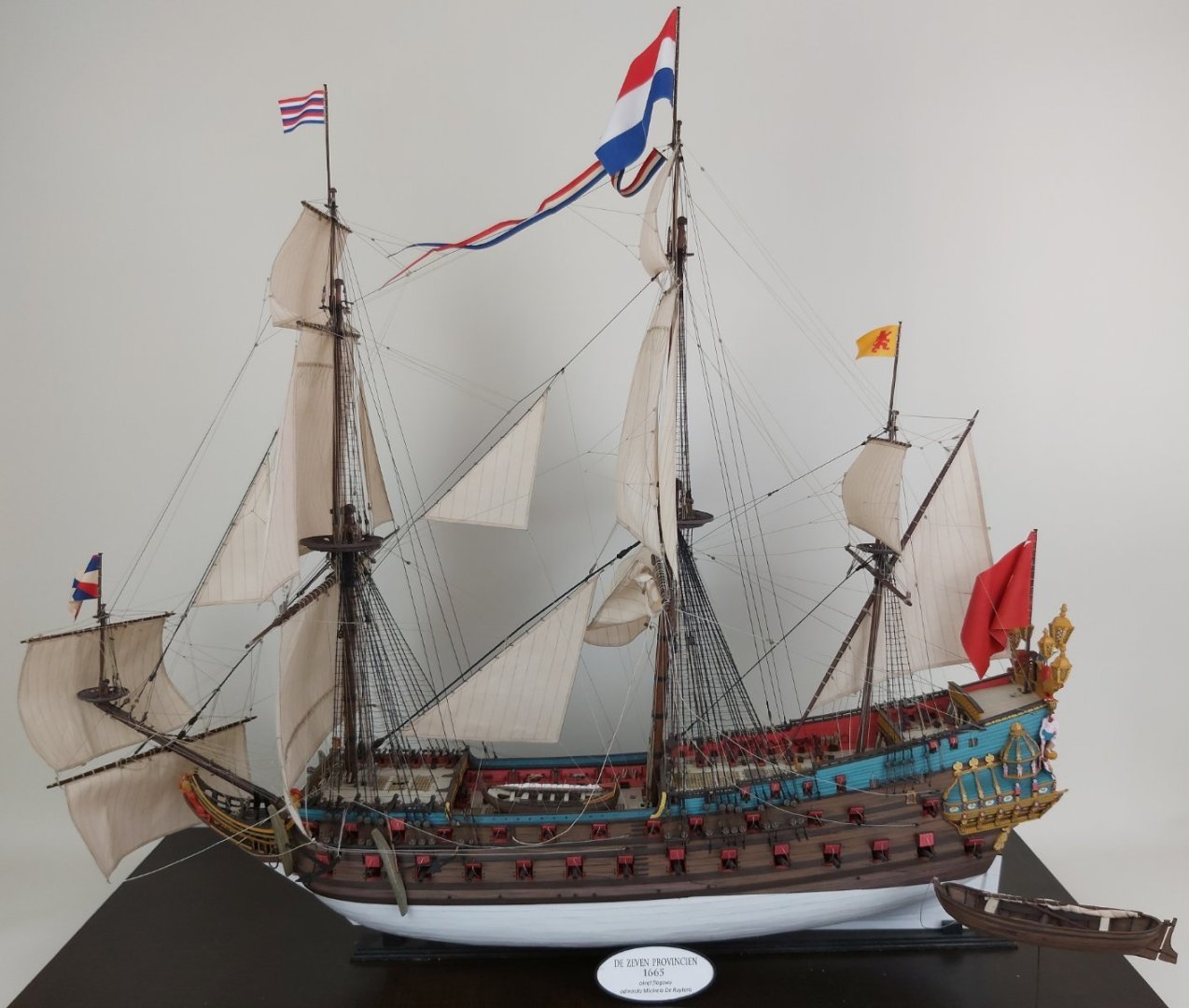
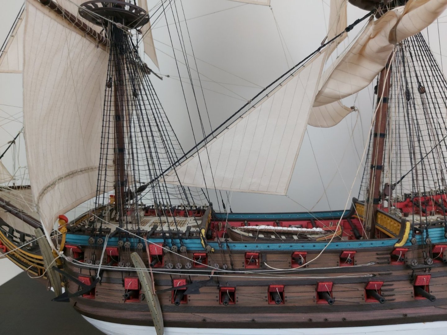
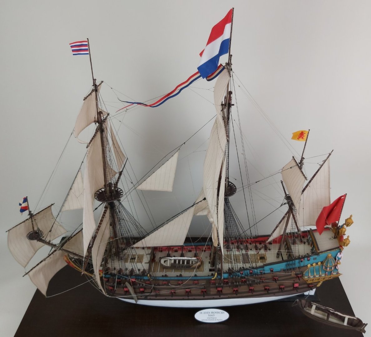
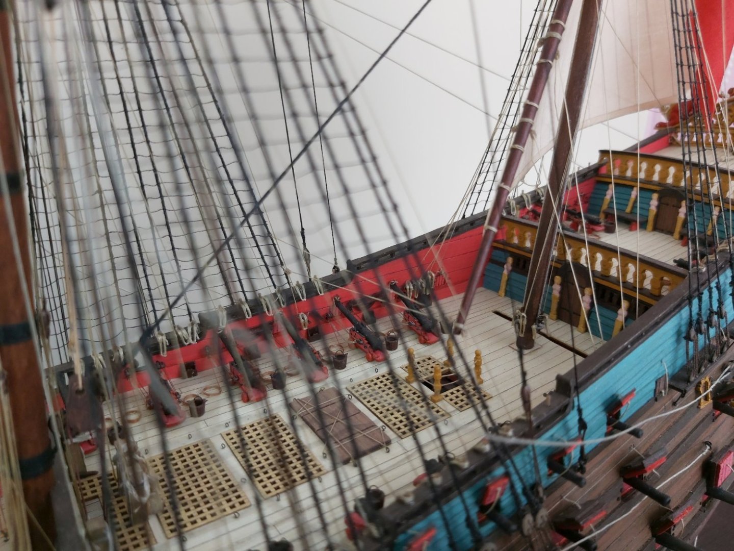
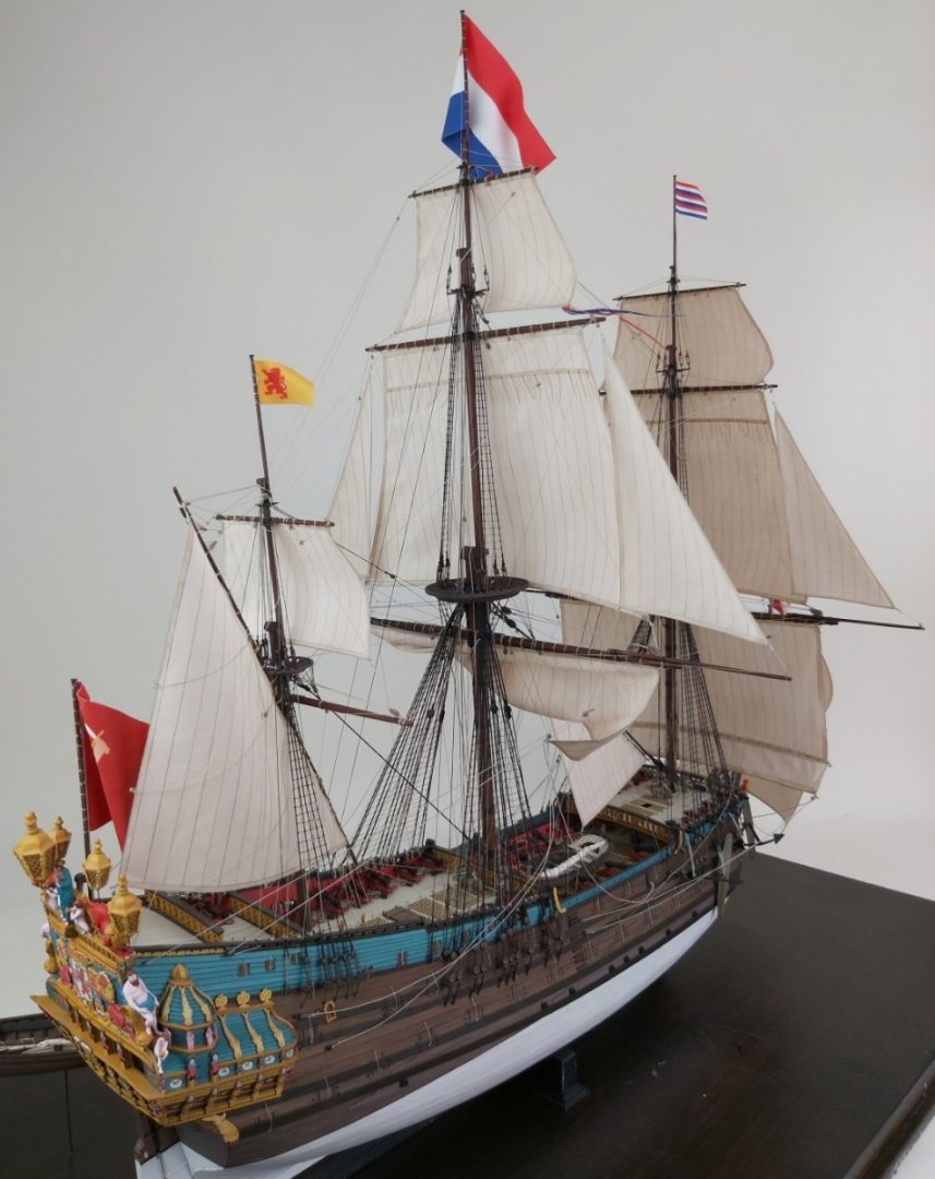
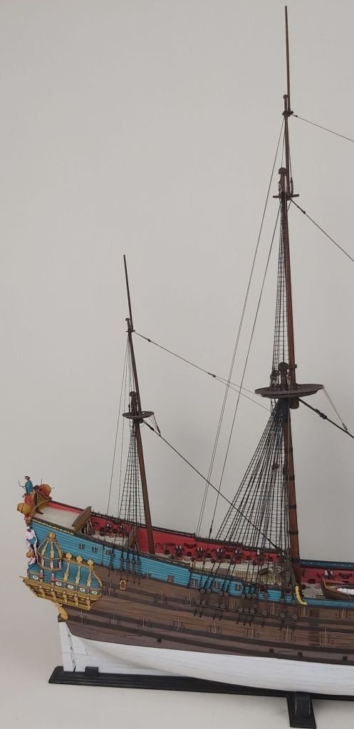
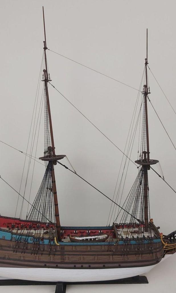
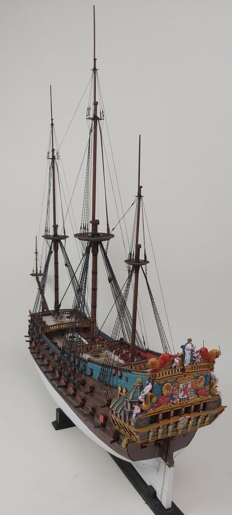
Hi everybody, yes, many months have passed since the last update, but I finally have something to be proud of - last night I raised the last flag and today I can show the completed model of the flagship "De Zeven Provincien". Thanks again to Ab Hoving, who constantly supported me, advised me and cheered me on until the last day of working on the model. Running rigging is so extensive that you can write an essay on what, how, where, what to watch out for, what to ignore, etc. I won't hide the fact that I simplified a few elements or simply "fooled" the human eye. I don't know how many ropes and threads are finally attached to the model. Although it was unlikely that all the sails were set at the same time, I decided as a test (after all, it is a test model) to hang the stay sails to make sure that there were no errors in the instructions or that any of the lines were placed absurdly. I used various sources, but I may have misinterpreted something (especially since some sources were in Dutch). Surprisingly, I found only one error (the designations of ropes 72 and 82 were swapped). I attached the rest of them according to the instructions and it worked. I made the first drawings in the project in the spring of 2017 (my daughter was 10, now 16). A handful of photos, comments and questions are welcome


- 26 replies
-
- 17
-
-
-
-
- Seahorse
- De Zeven Provincien
- (and 2 more)
-
Thank you, Chris, for presenting the news. The more precise adrress😉 Seahorse shop. Regards Tomasz Weremko
-
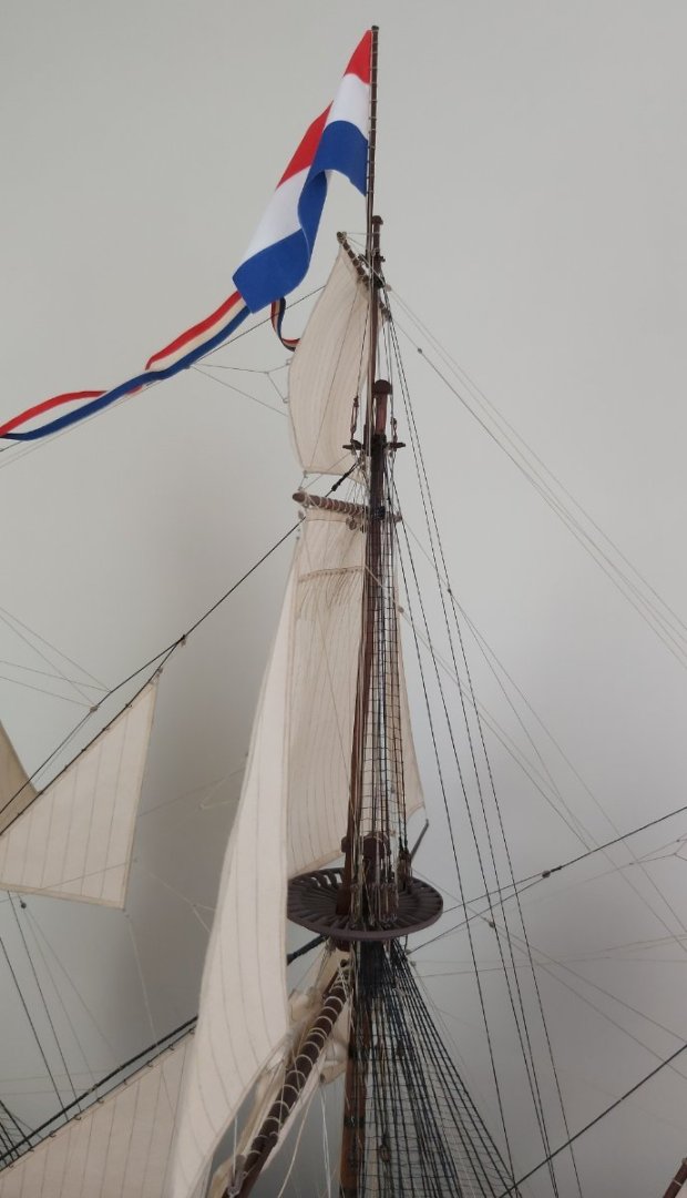
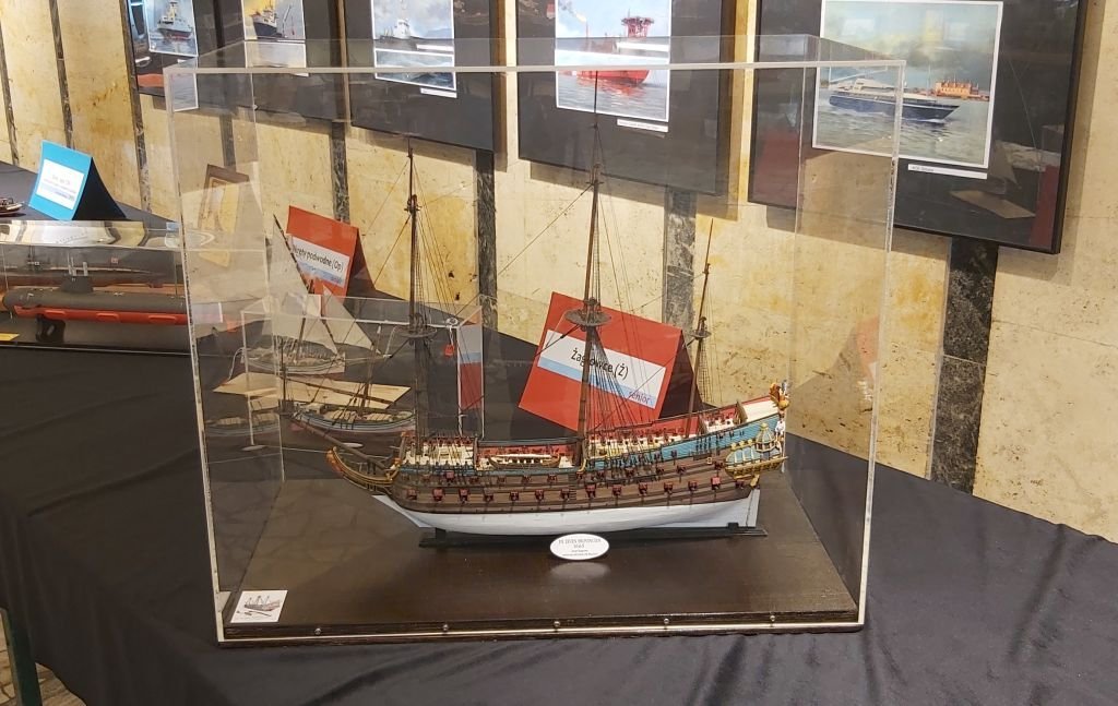
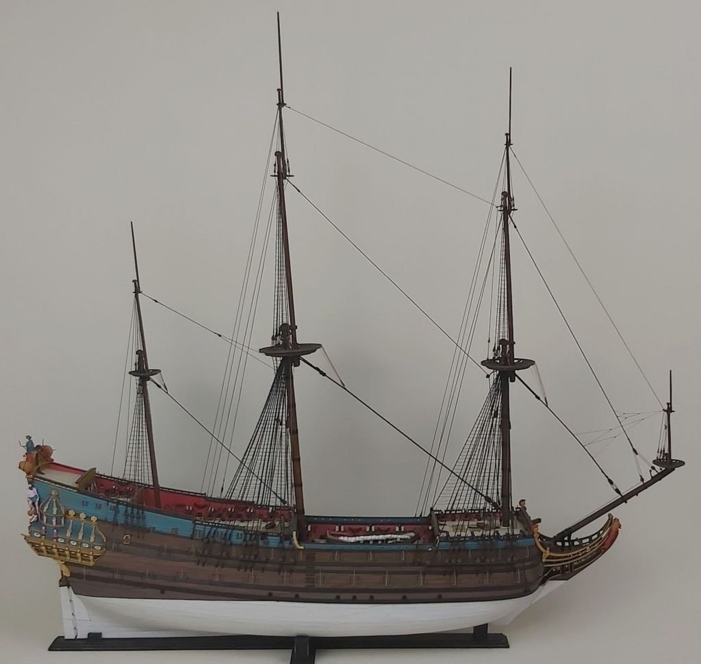
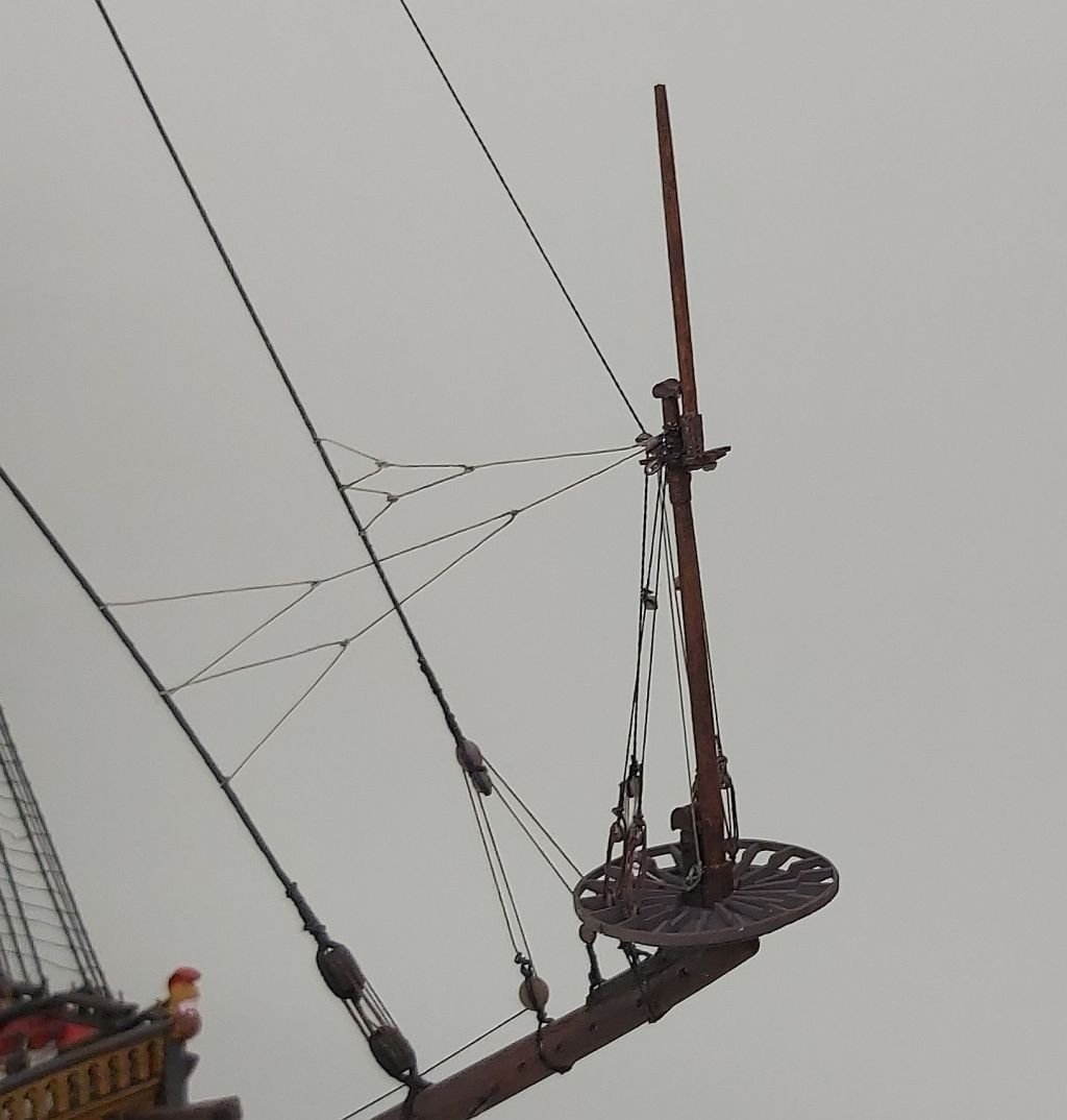
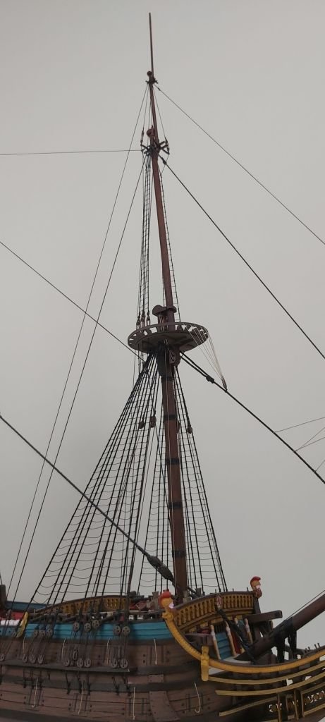
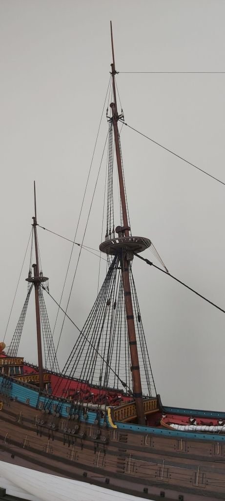
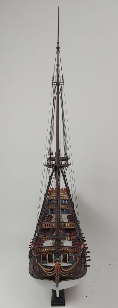
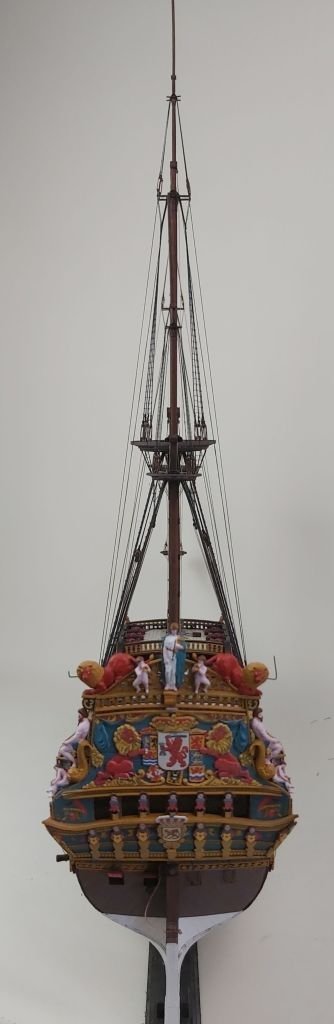
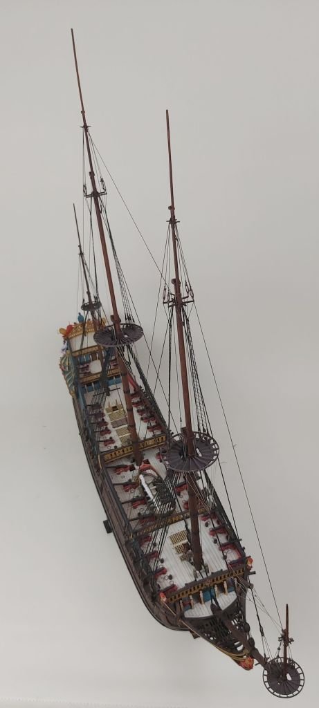
Hello, I can't believe it's been so long since the last update. I have put up all the masts and I think you can say that the standing rigging is ready. Most components built/rigged as planned. A slight problem arose with the bowsprit mast and the foremast: both leaned back slightly when tensioning the stays, which was not matched by the stiffness of the bowsprit (it moved up a little). I am satisfied with the symmetry: with such a large sailing ship, I managed it almost perfectly. Some time ago, the model, unfinished but secured in the "aquarium", made its first cruise at the Model Show in Nowy Tomyśl. The latest photos of "De Zeven Provincien": Tomek
- 26 replies
-
- 15
-
-
-
-
- Seahorse
- De Zeven Provincien
- (and 2 more)