HOLIDAY DONATION DRIVE - SUPPORT MSW - DO YOUR PART TO KEEP THIS GREAT FORUM GOING! (Only 24 donations so far out of 49,000 members - C'mon guys!)
×


Mr Pleasant
-
Posts
57 -
Joined
-
Last visited
Content Type
Profiles
Forums
Gallery
Events
Everything posted by Mr Pleasant
-
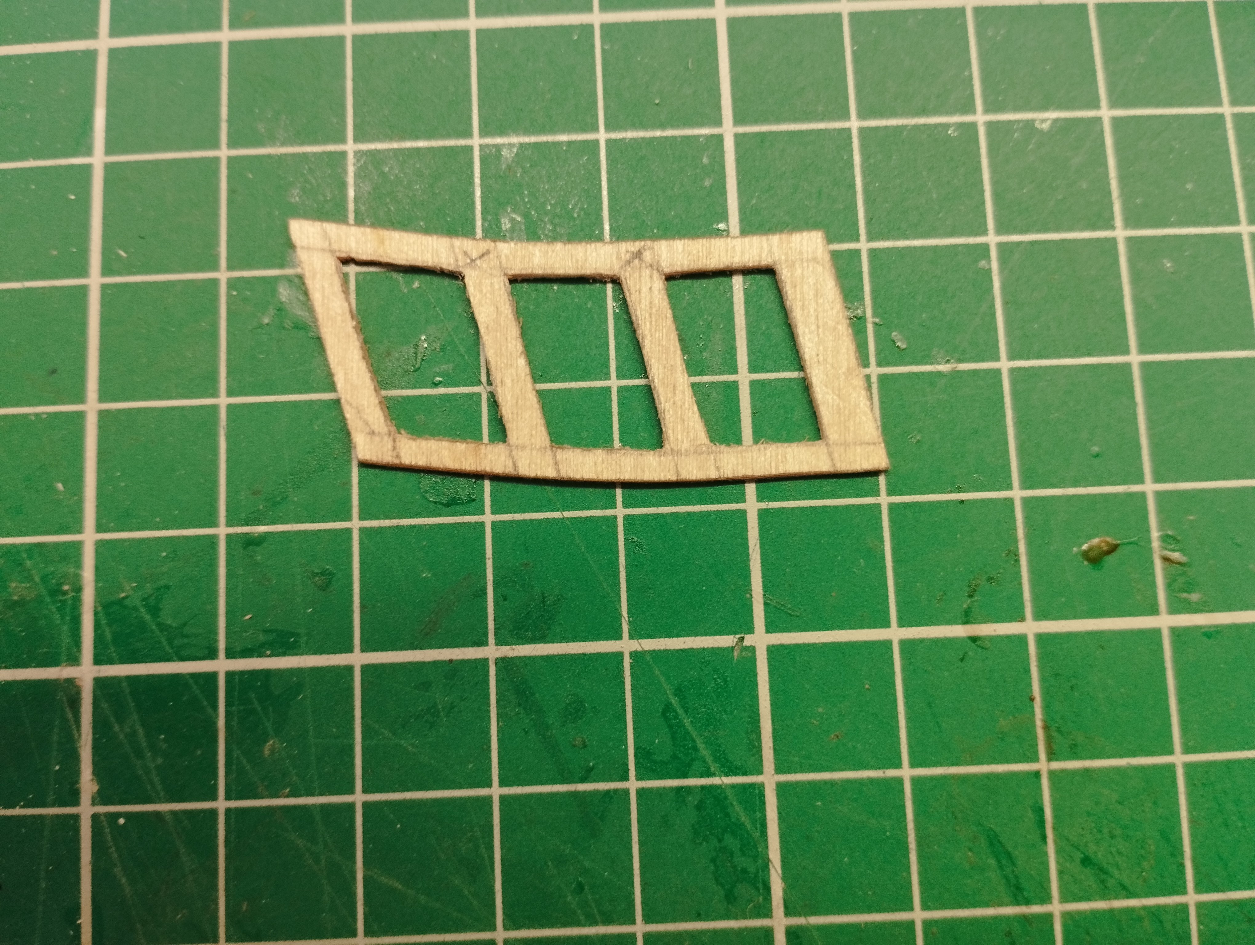
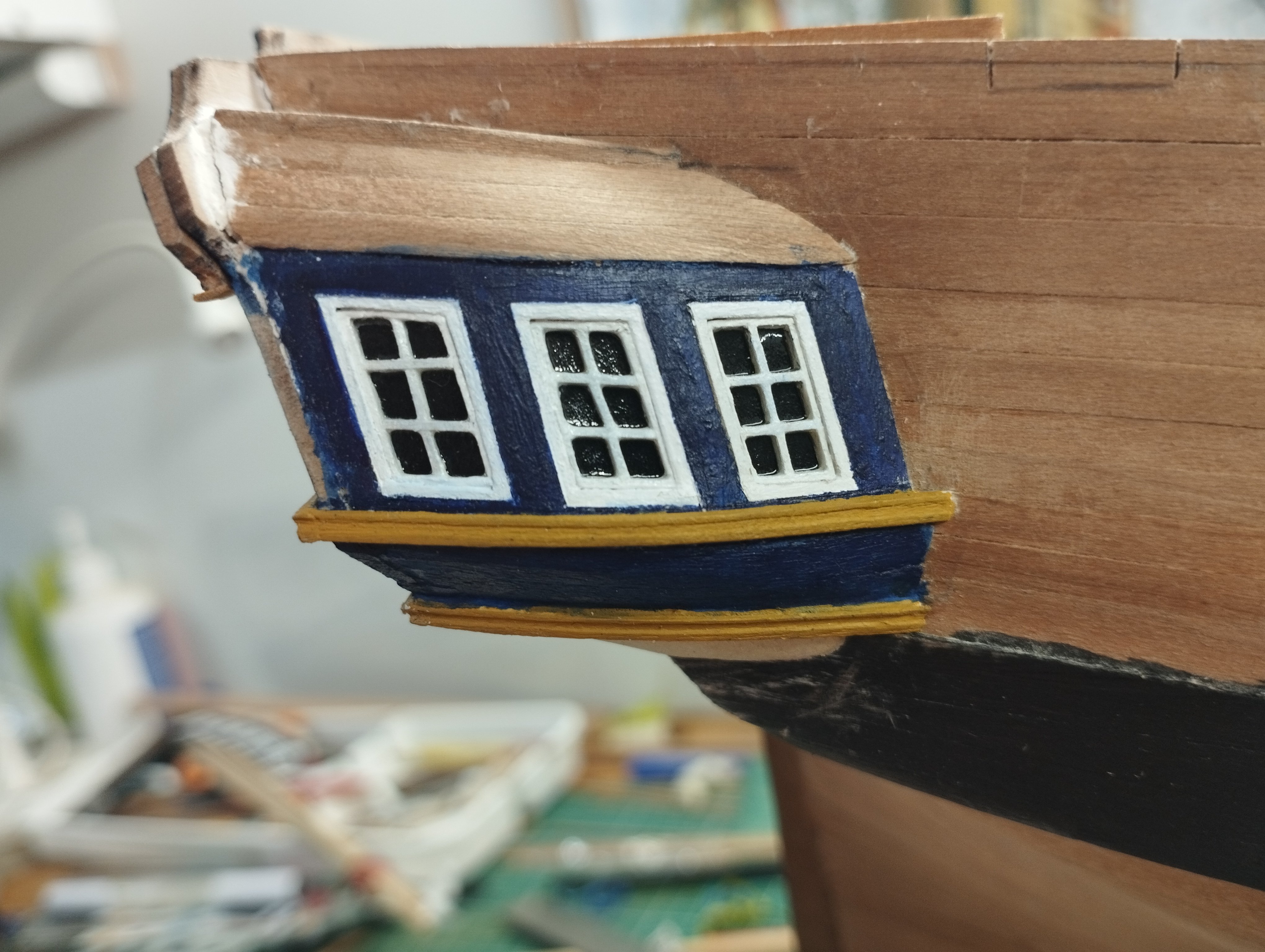
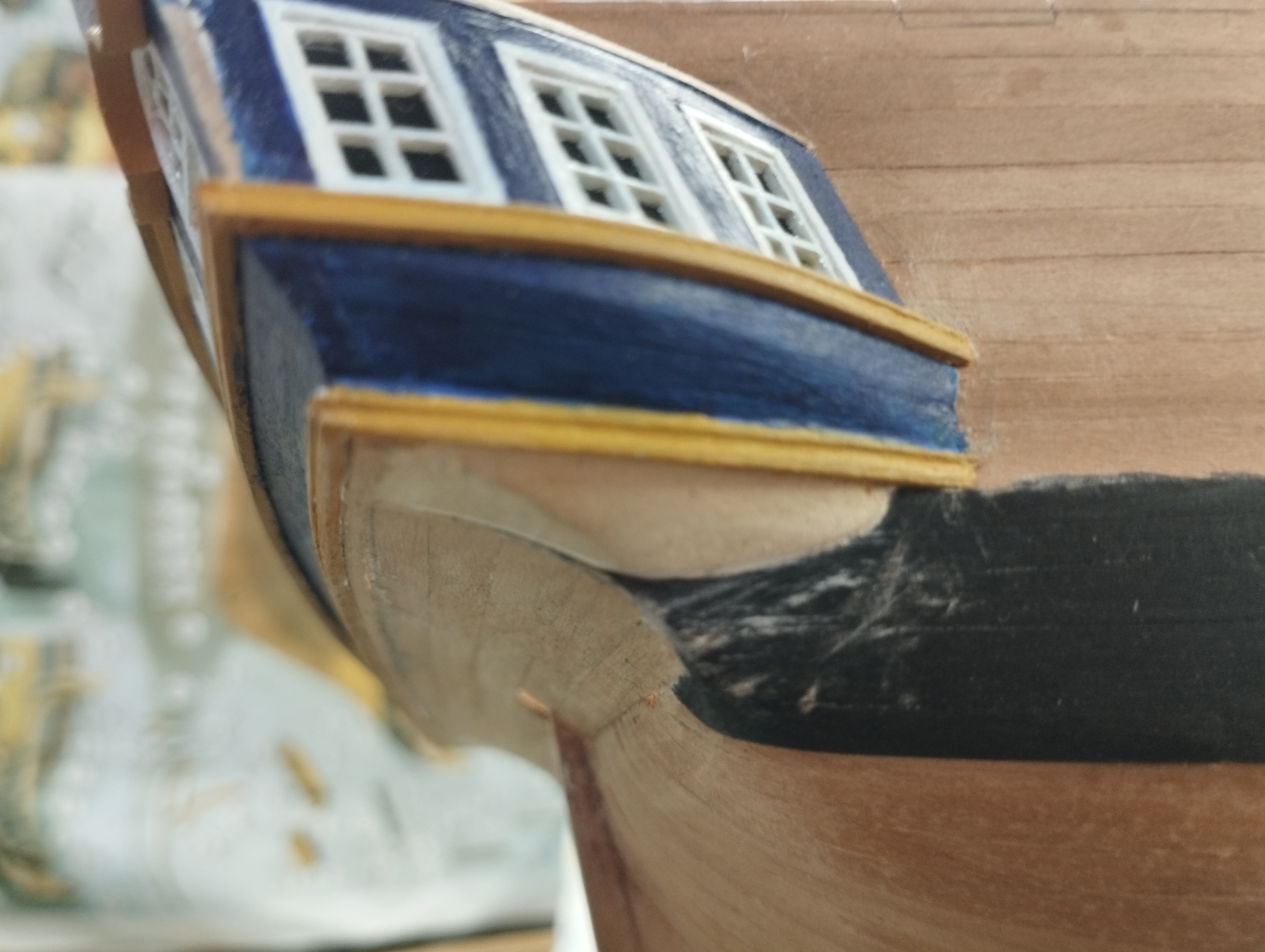
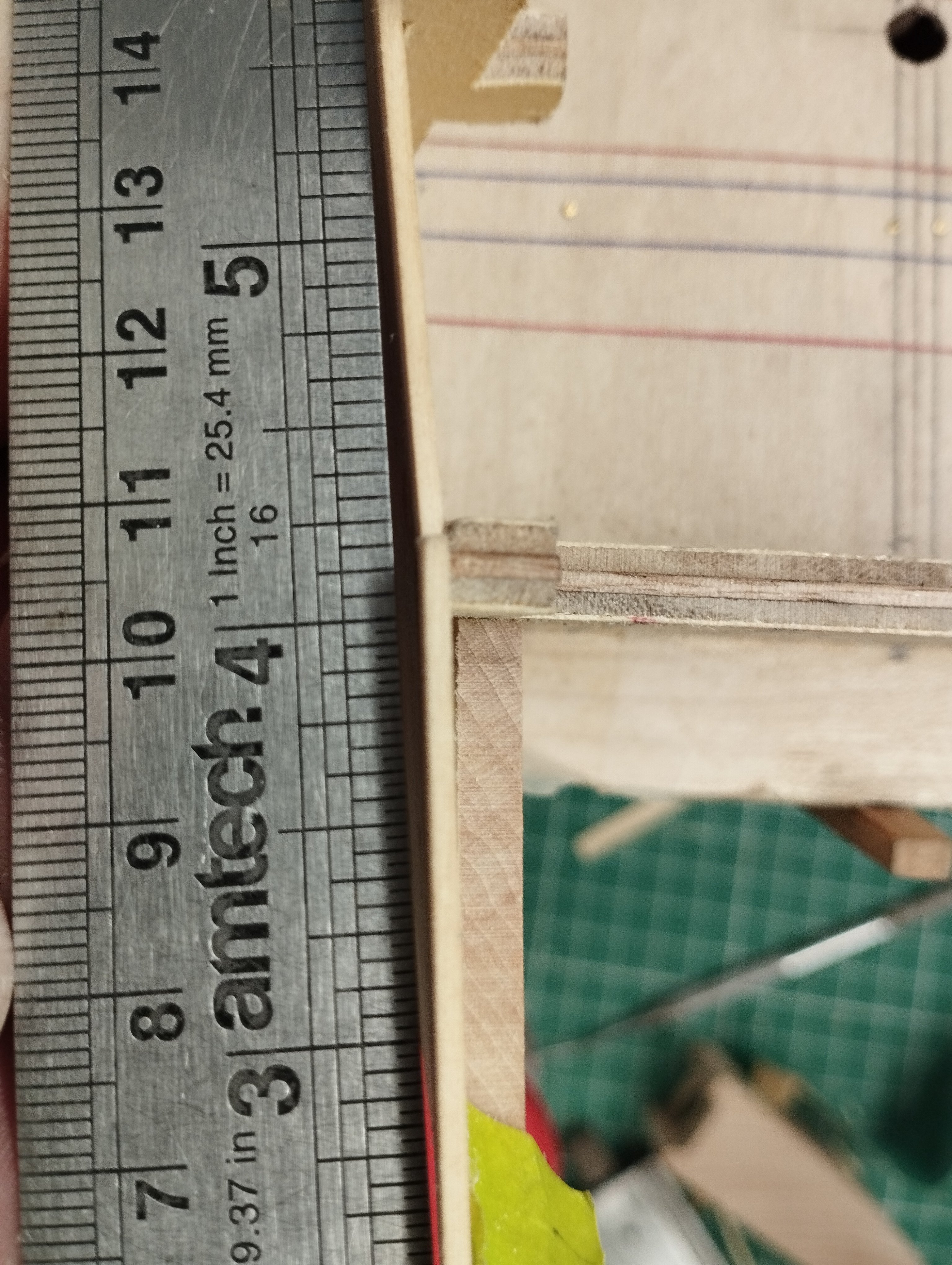
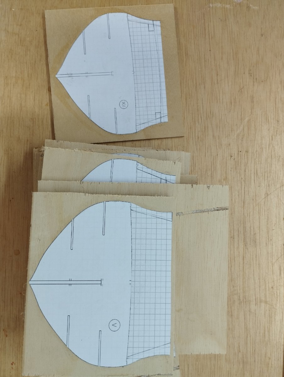
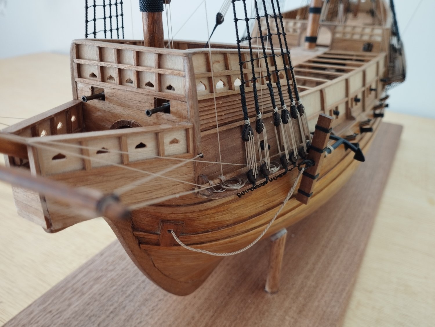
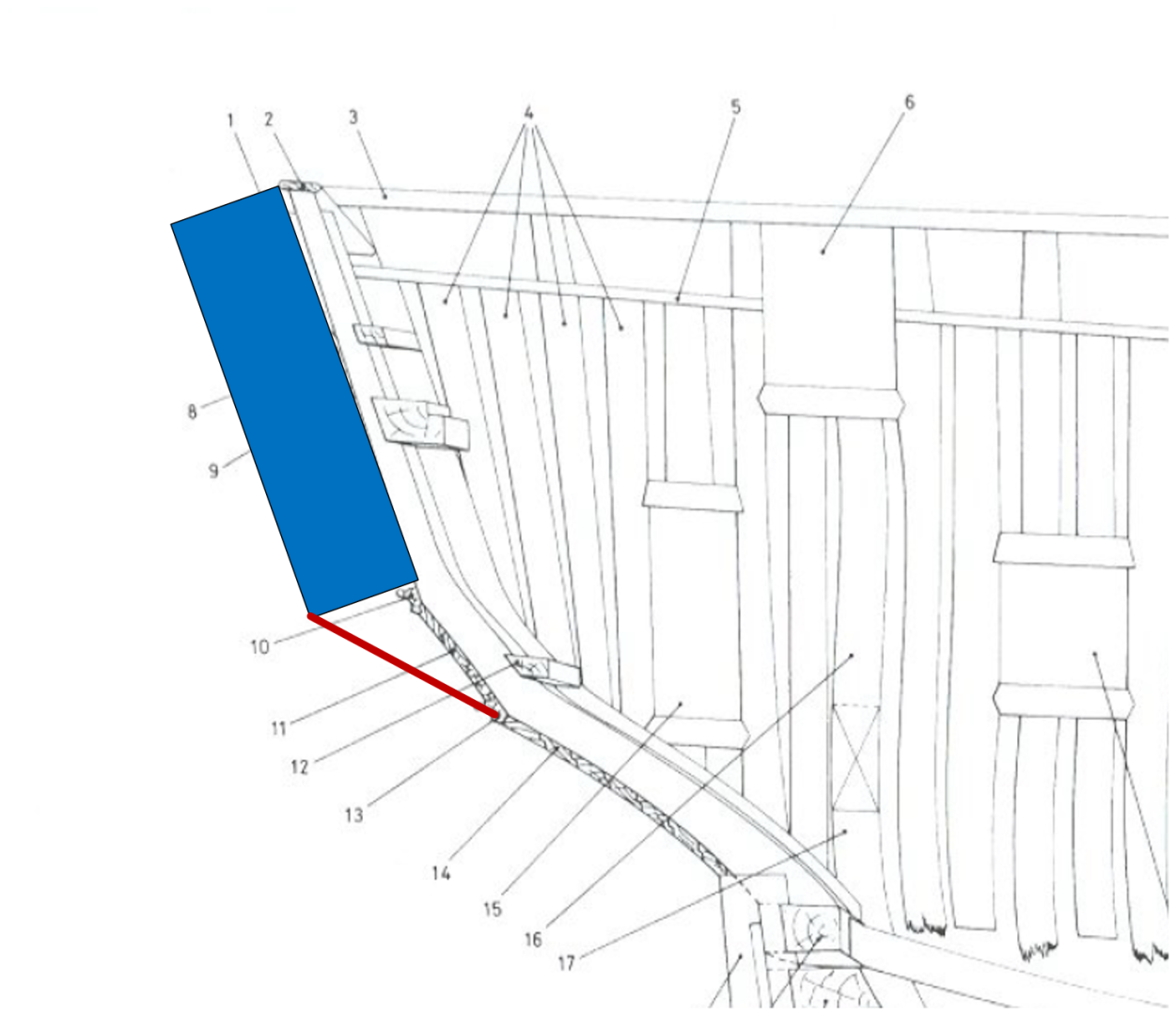
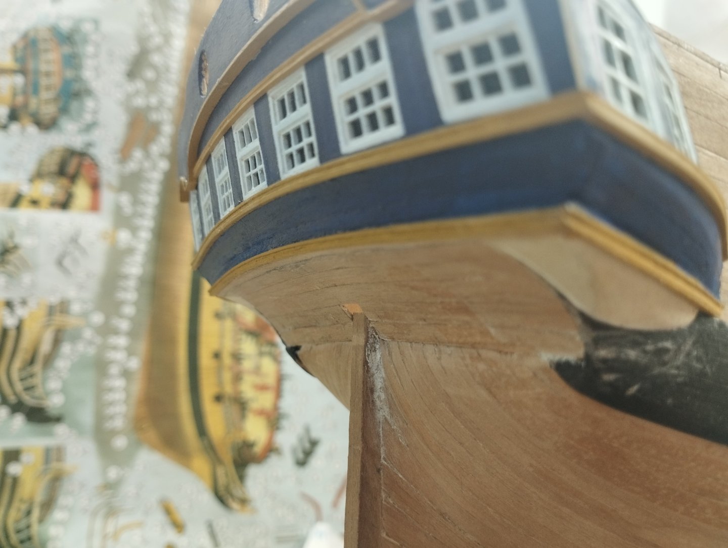
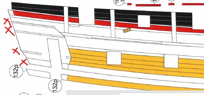
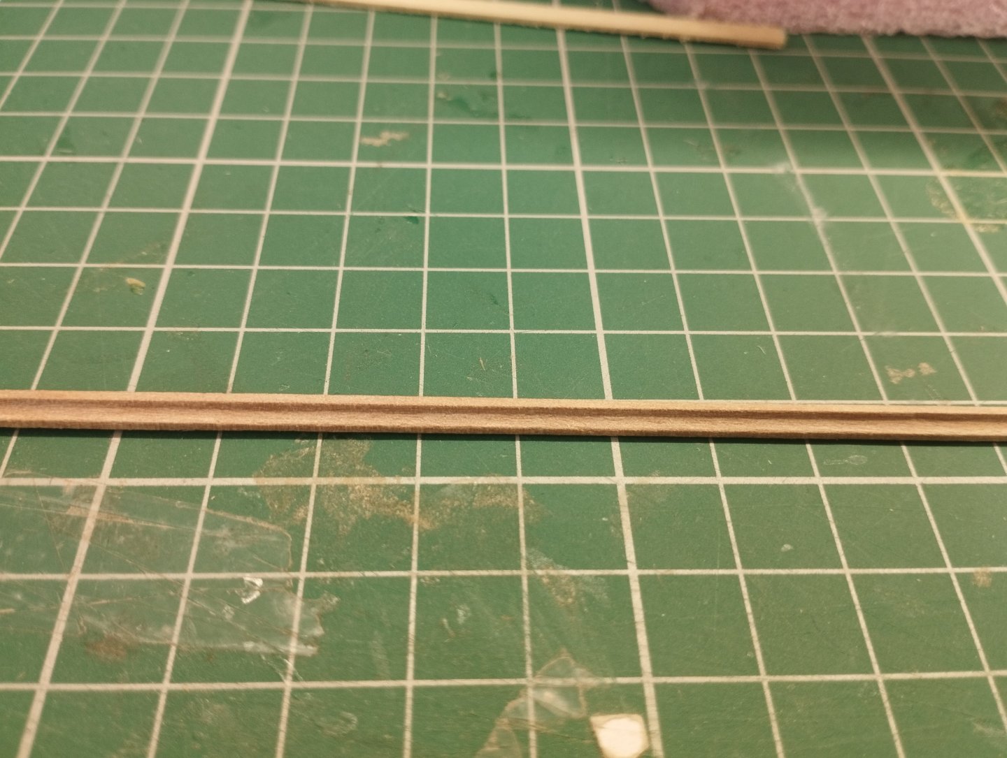
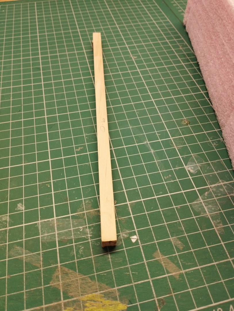
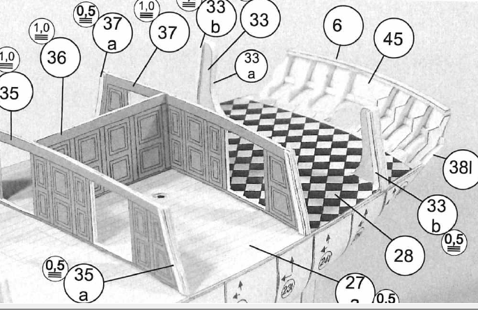
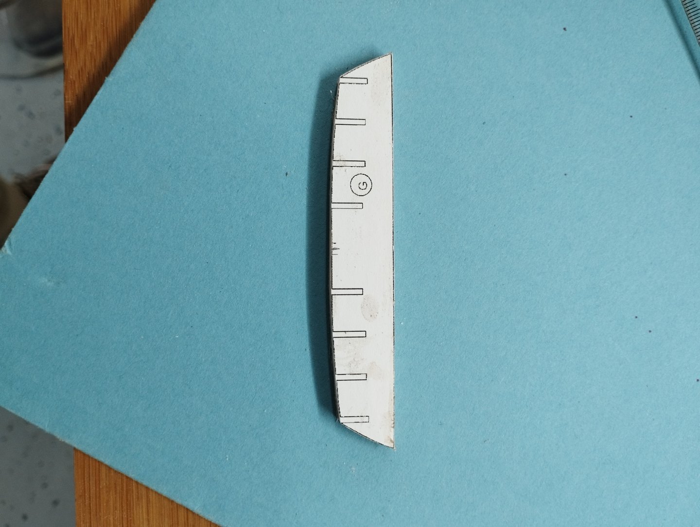
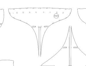
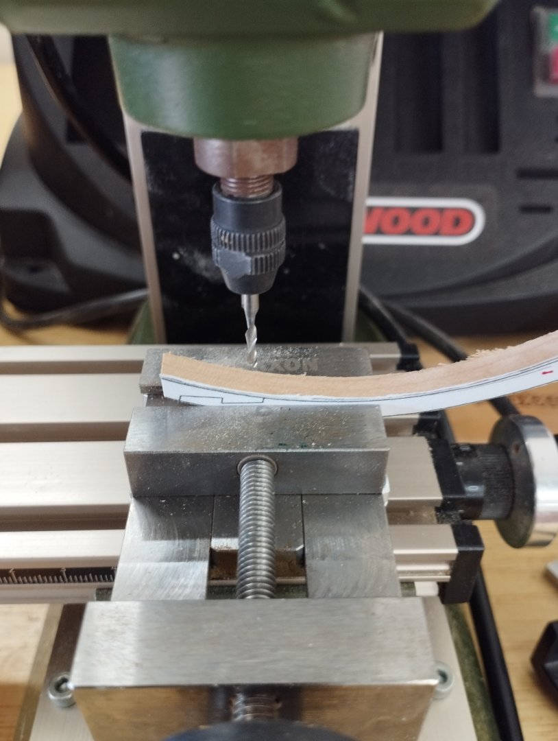
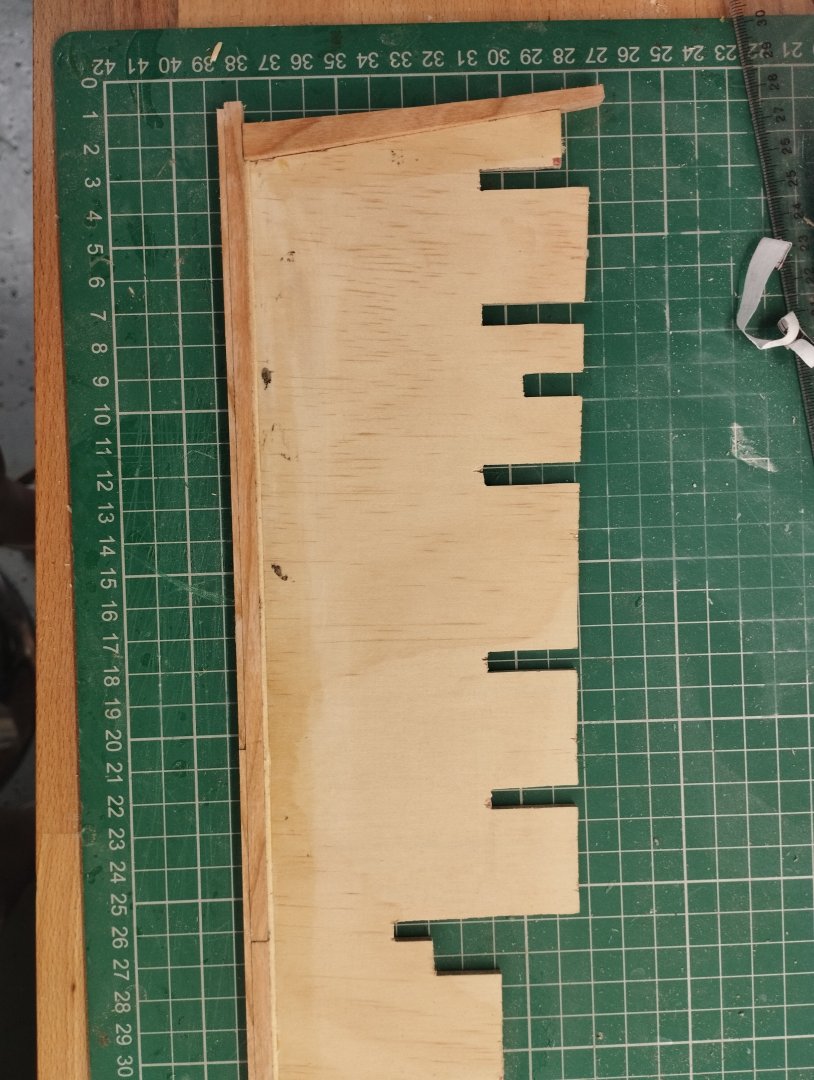
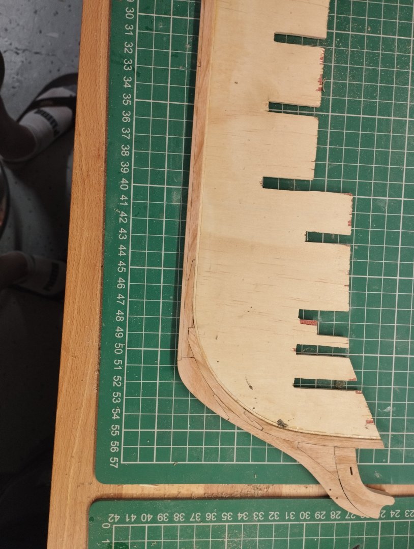
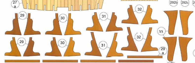
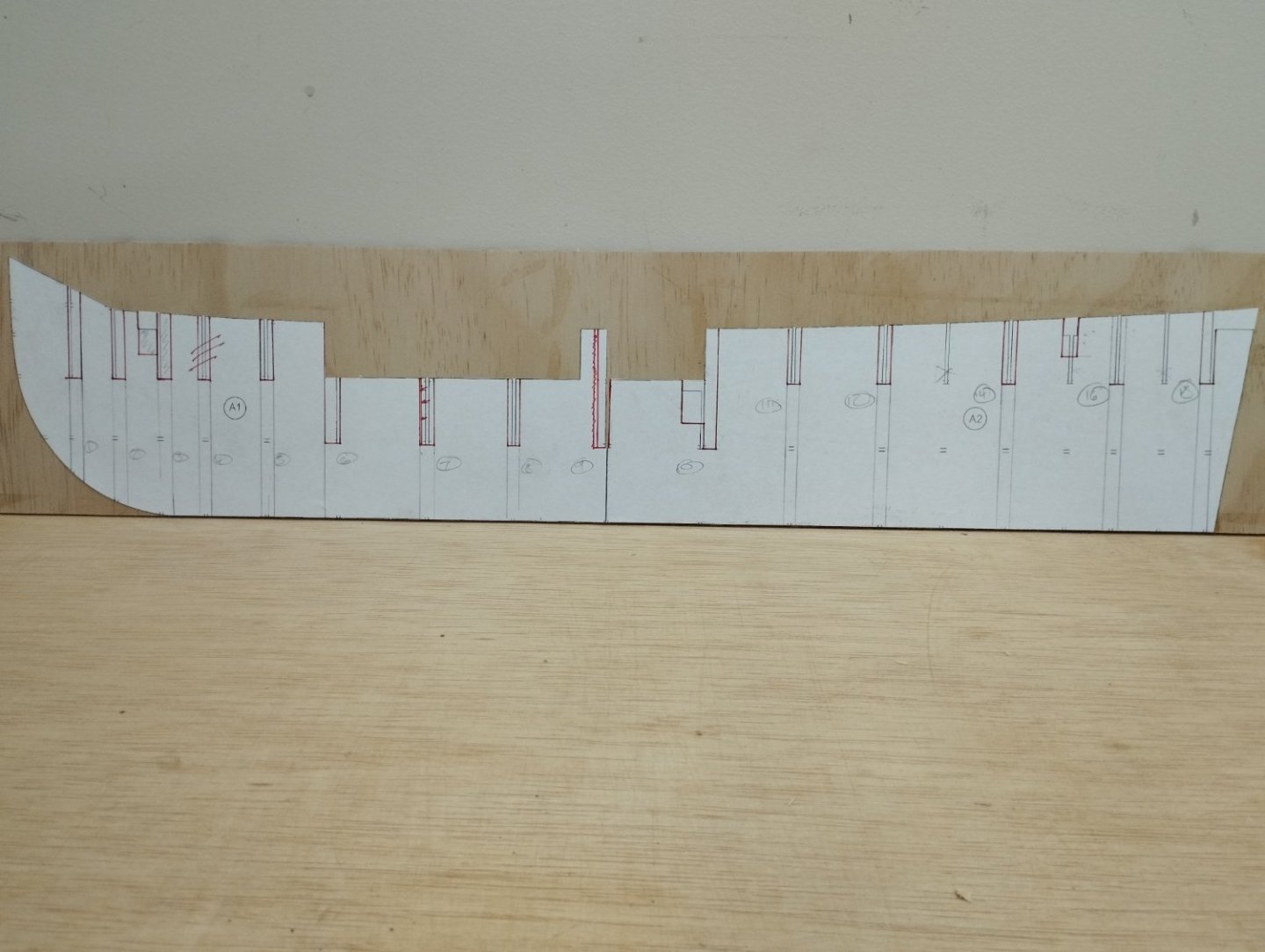
Hi All Work has been continuing on the stern area. The paper model gives the below and this is the look I'll be aiming for with some slight differences in colour scheme First things first was to determine the template to make. I'm slightly wider than the paper version due to the width in planking, I'd purposefully not made allowance on the bulkheads for the thickness of the double planking compared the requirements if this was been made out of paper and also referring to post #9 we can see the back has flared out a little (picture with ruler). I wanted to keep the shape at the edges so I cut two templates from those provided and slipped one behind the other to get the width whilst keep the height and edges correct. Once this was done it was a matter of arranging the windows to cater for the increase in width Windows were then drilled out and a the fascia made and holes created for the stern chase ports. Its worth noting at this point that the piece was made with 2 x 1.5mm ply resulting in a 3mm piece and the facia made with 1.5 mm ply....more on this later Widows were then created with 1mm x 1mm cherry for the outer frames and 1mm x 0.5mm for the inner. The small arches in the window frames were made with the aid of a 2.5 mm drill bit in a soldering iron, wetting the wood and using the heat to bend into shape and then cut to size So far so good....until coming to fit it on the ship!!!. With making the piece 3mm thick it didn't lend itself to fitting in with the planking on the upper counter. I've tried to show the issue below using Diana from AoTS as a background with the blue rectangle representing the 3mm stern piece and the two options I considered Option 1 on the left would have left the stern piece proud of the planking Option 2 on the right would require a single piece fitting to marry the planking and stern piece together as shown by the red line. Neither option was ideal but option 2 was closer to reality...despite knowing I wouldn't be happy I tried it in any case. I tried hard to convince my self that with a bit of filling, sanding and painting that I could live with it and also acknowledging the angle of this piece would make it difficult to see the name of the ship, but who looks at the back of the ship I kept telling myself. After days of inner turmoil in trying to persuade myself that everything would be good and I that I could live with it, I elected to remove it an start again. This time I stuck to a single piece of 1.5 mm ply and went through the processes above and that allowed the planking and stern piece to come together nicely. I don't have a straight after photo but this is how it came together Next was to make the columns between the windows To make the pedestal and associated top piece I scraped a channel in a 1.5 x 1.2 mm strip and made a jig to cut consistent angles. Once this was complete i drilled a hole slightly into the angled side resulting in this...bit small i admit, I probably should have zoomed in a bit more Once painted they were glued in position and masking tape used to determine the height and angle of the column. The tape was forced to make a crease with a pencil and this gave me the template to stick onto a piece of stock to cut/sand to the correct angle. I then milled groves to try and simulate a column To finish off the stern chase ports i reduced a dowel to the correct diameter and created a tube using the milling machine and the dividing head to turn the dowel as I moved the bit. The lettering for the ships name was simply printed onto paper and painted....I may revisit this a later date. After a fair amount painting, repainting, masking and repainting I'm finally at a point that I'm fairly happy with but there is still a way to go to complete this area Thanks for dropping by Mark


-
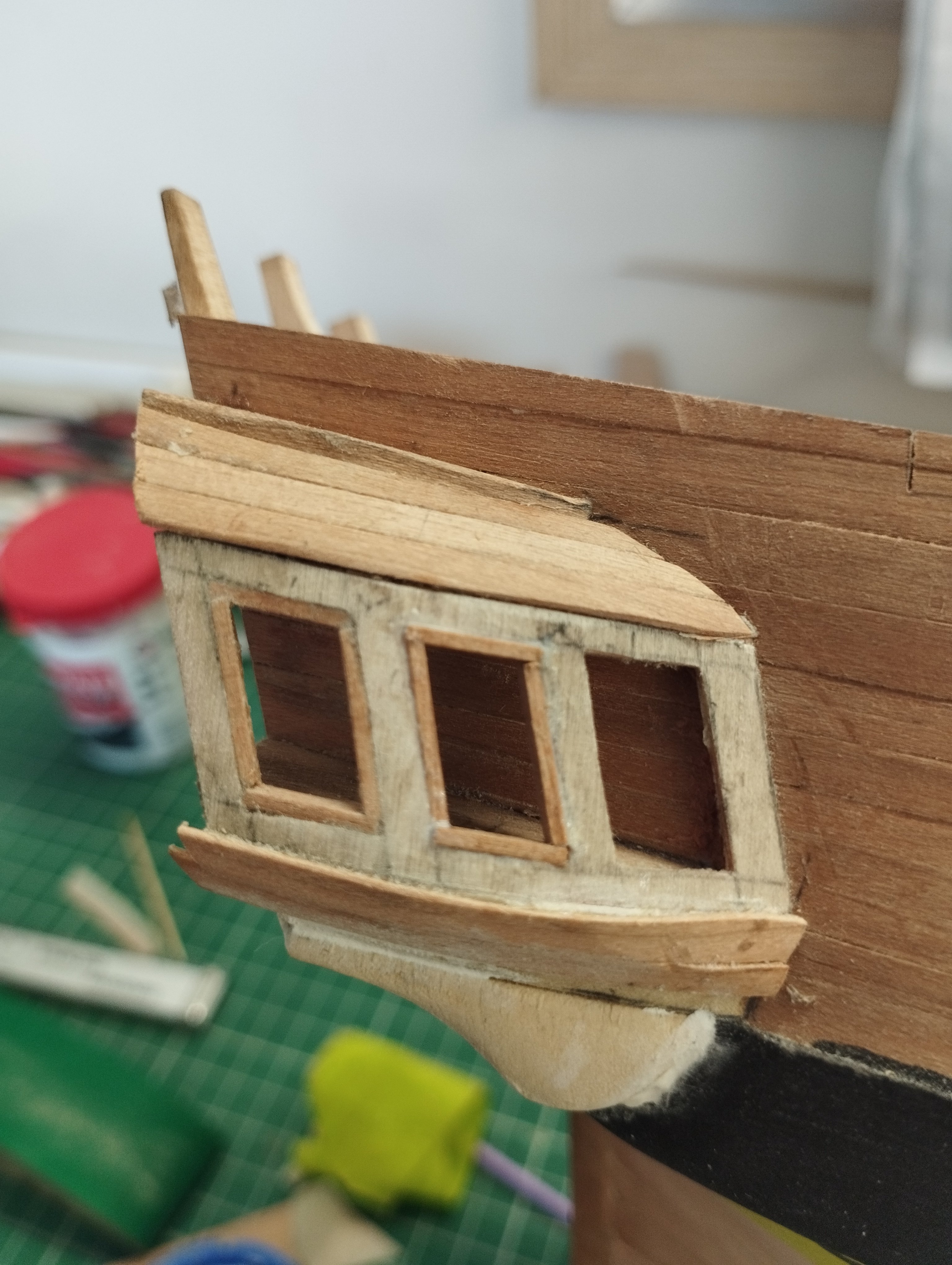
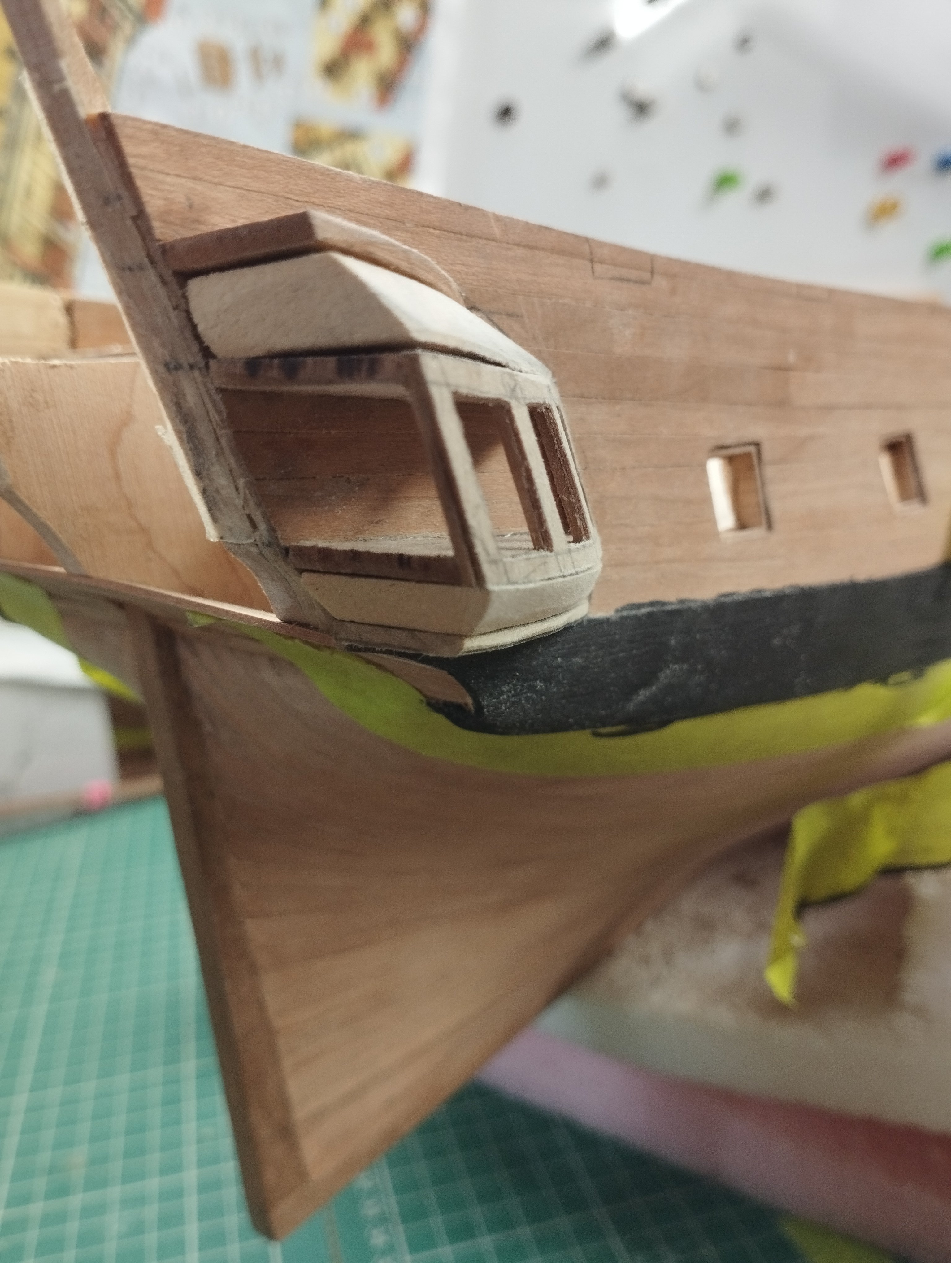
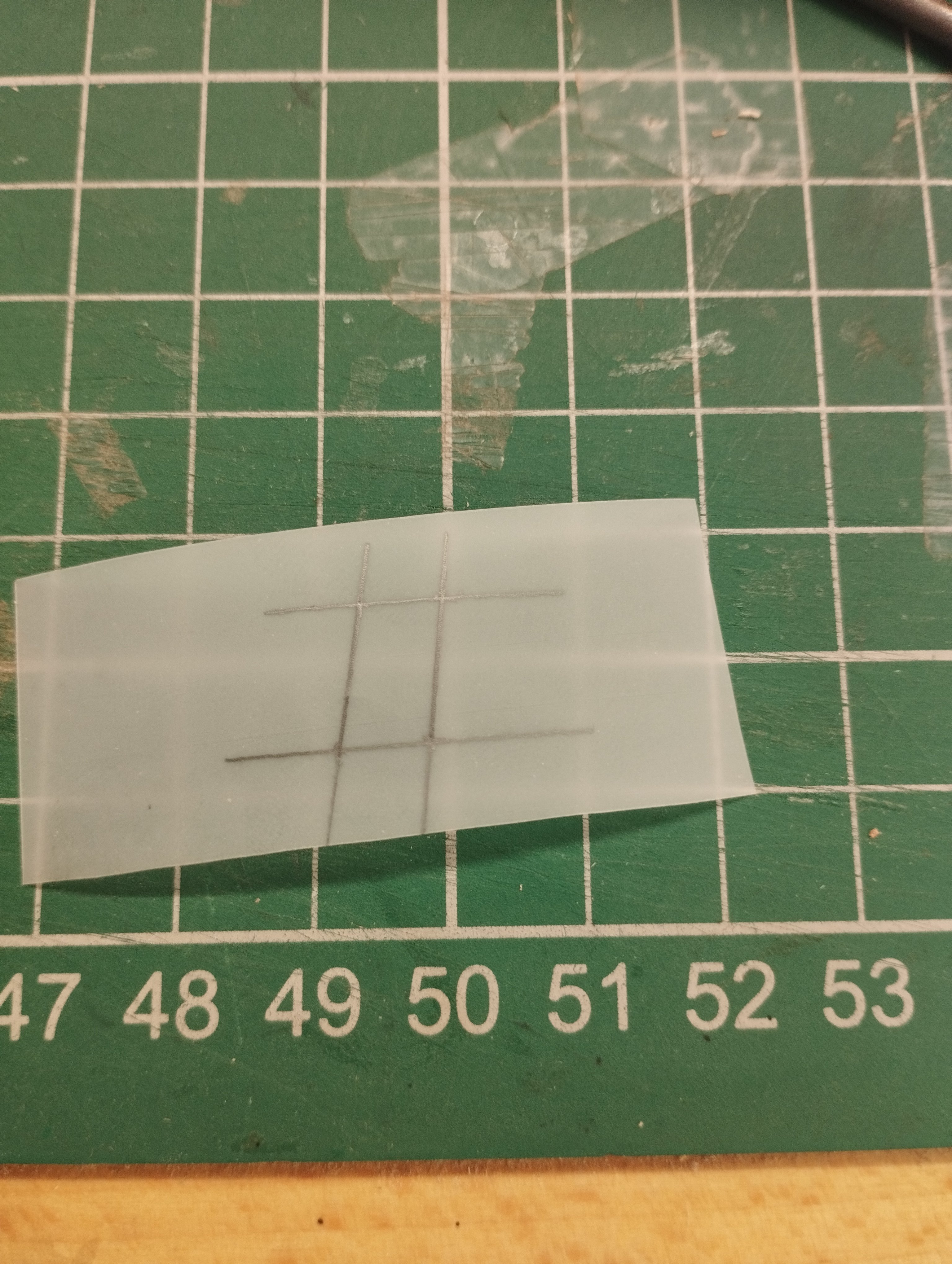
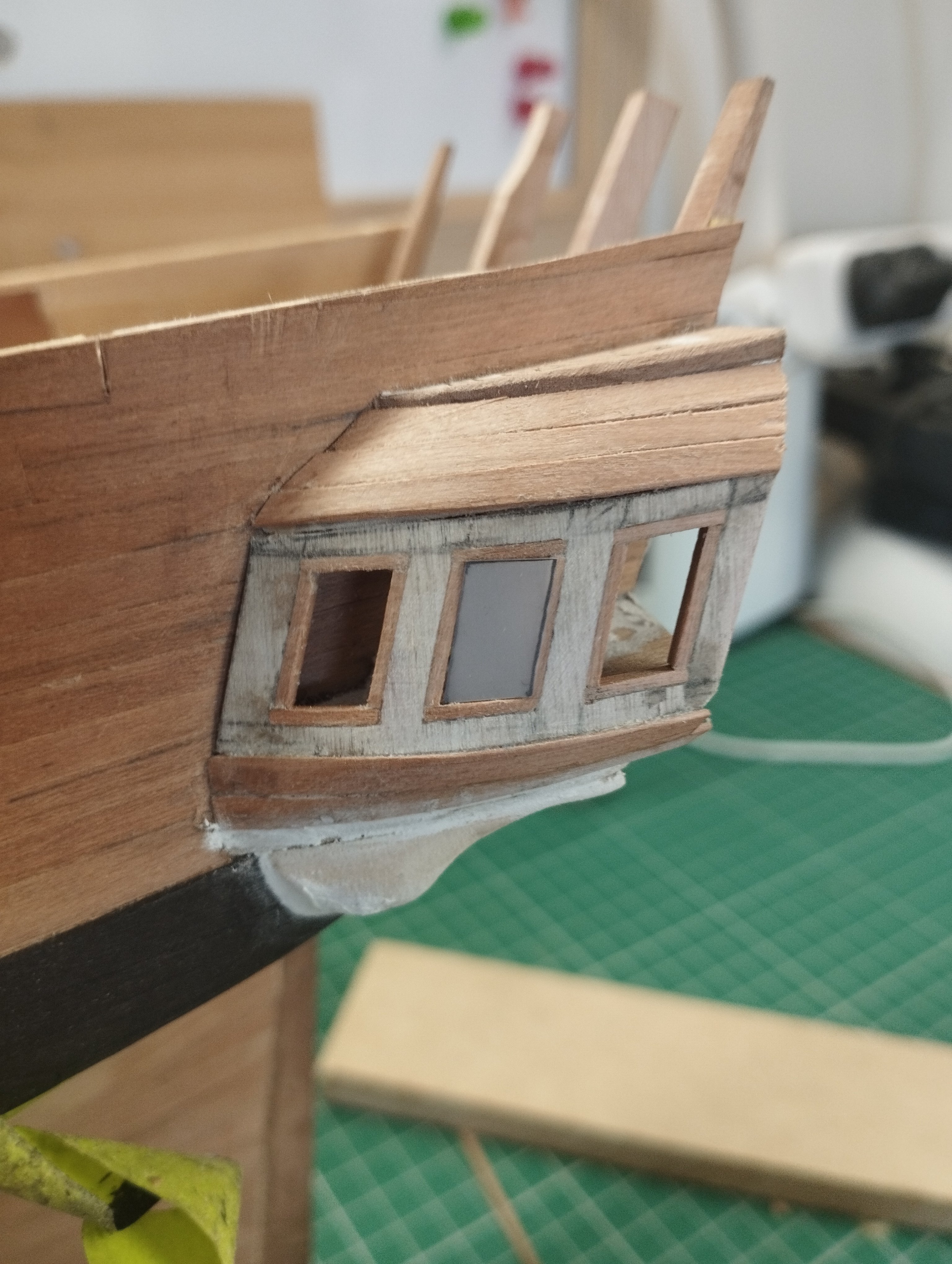
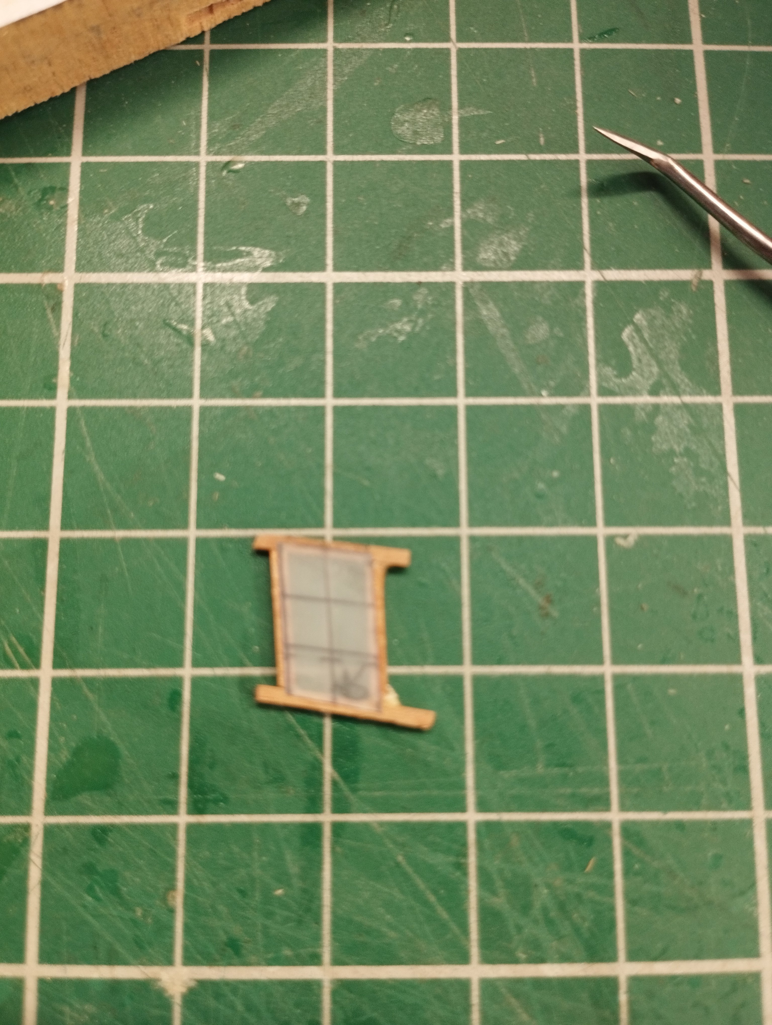
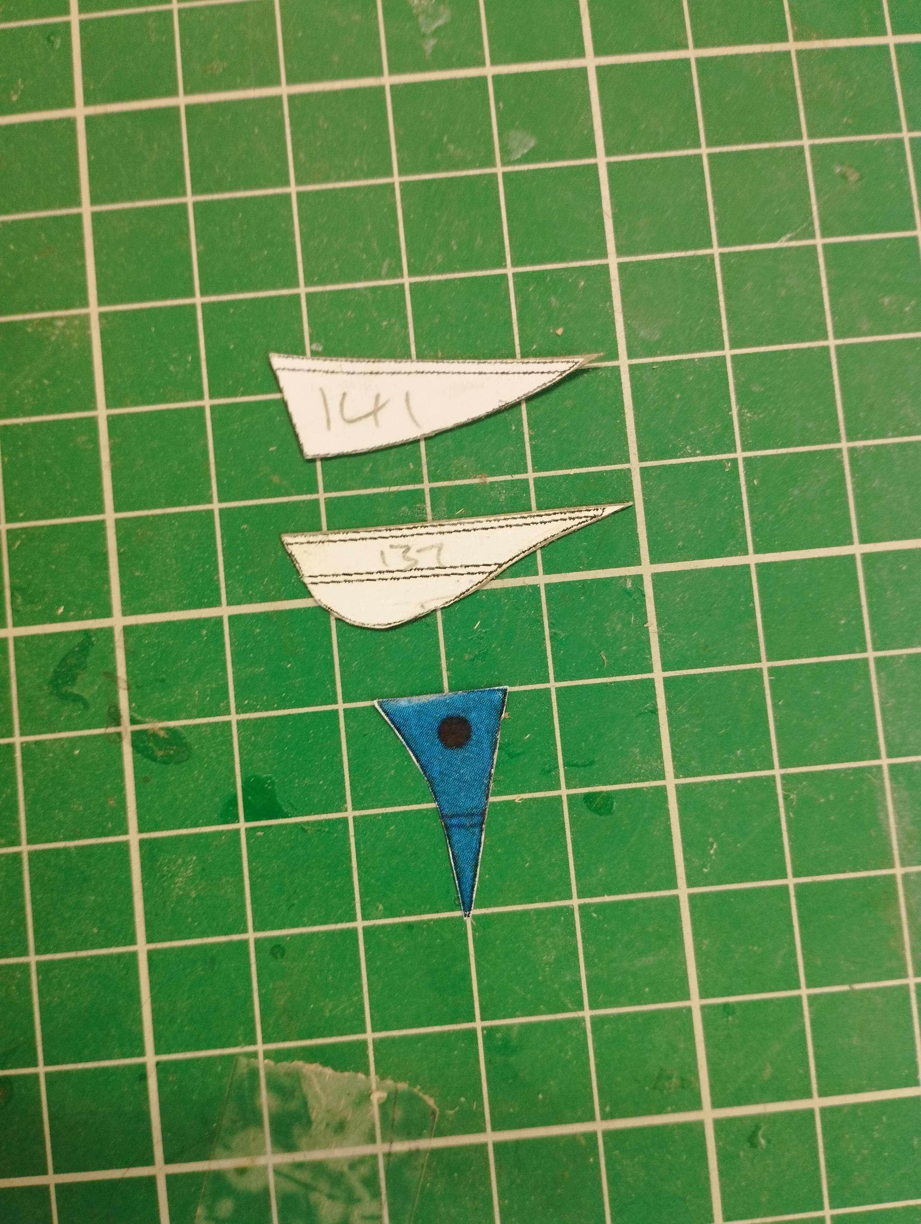
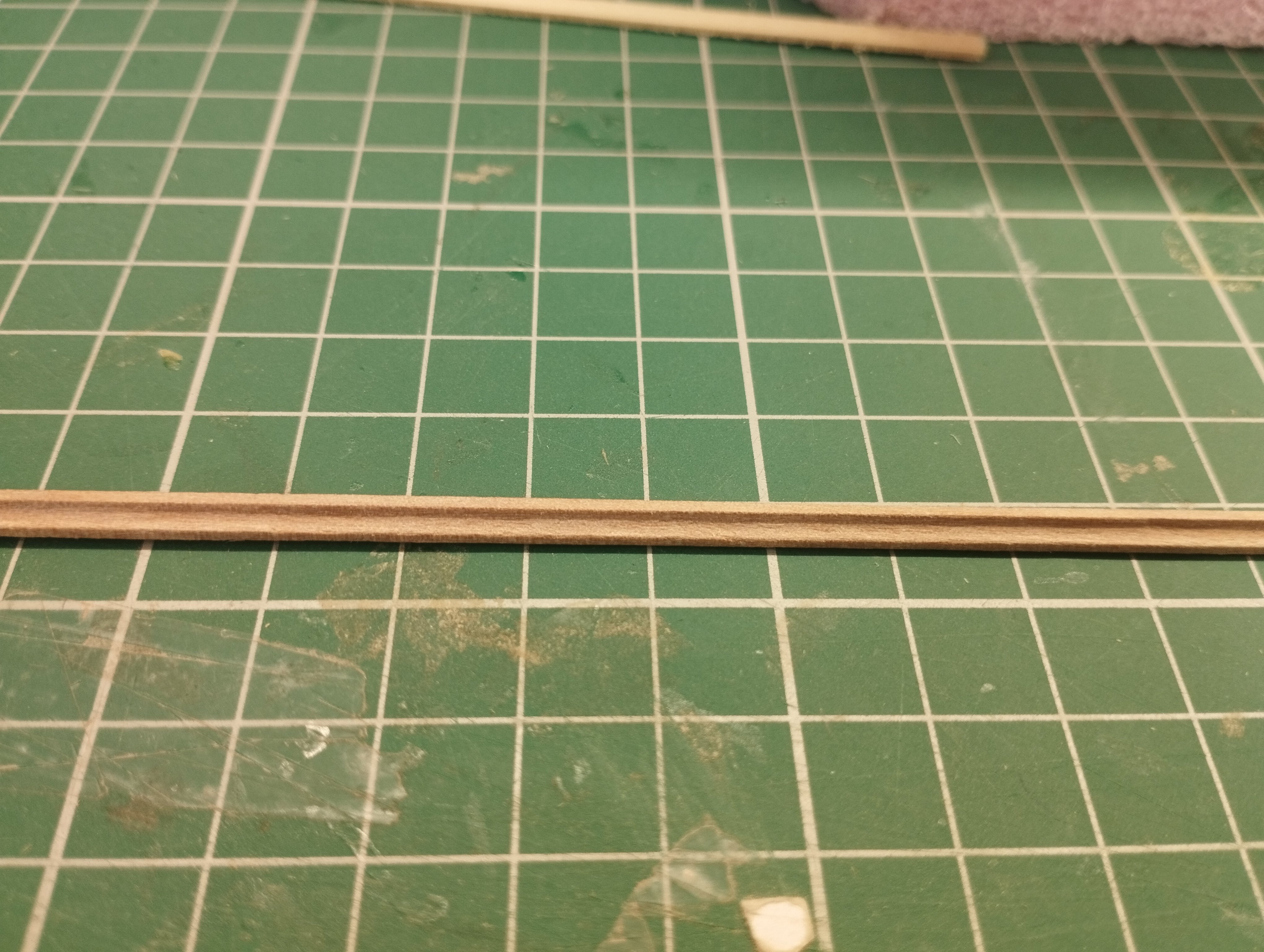
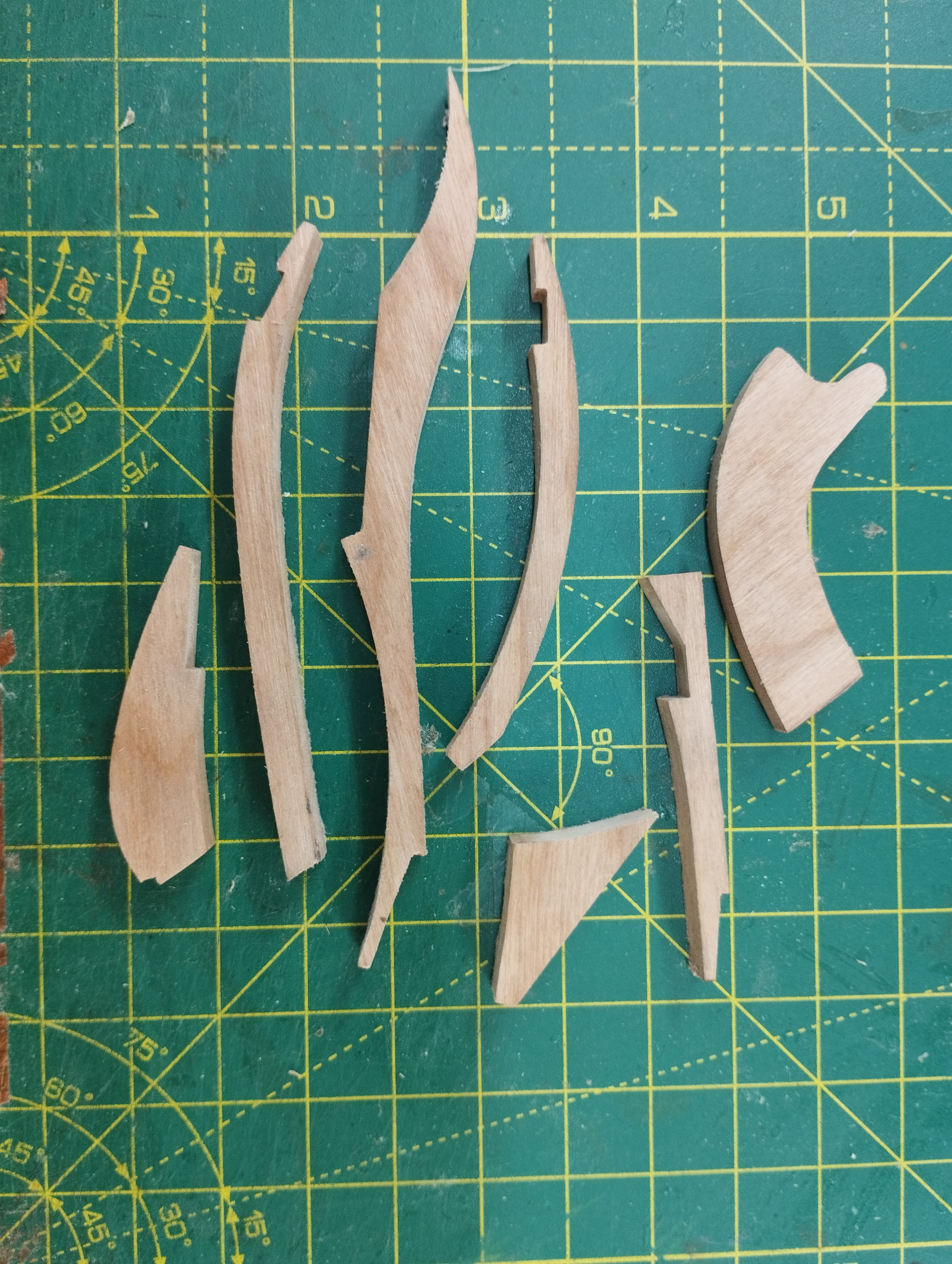
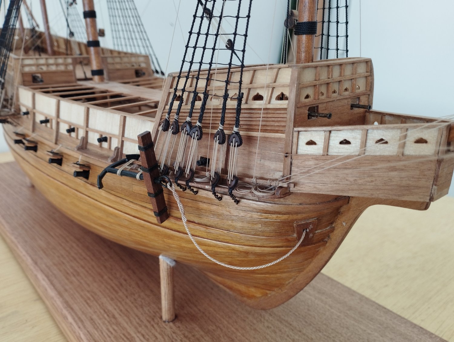
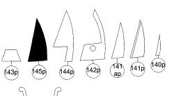
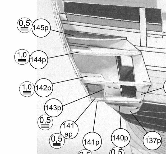
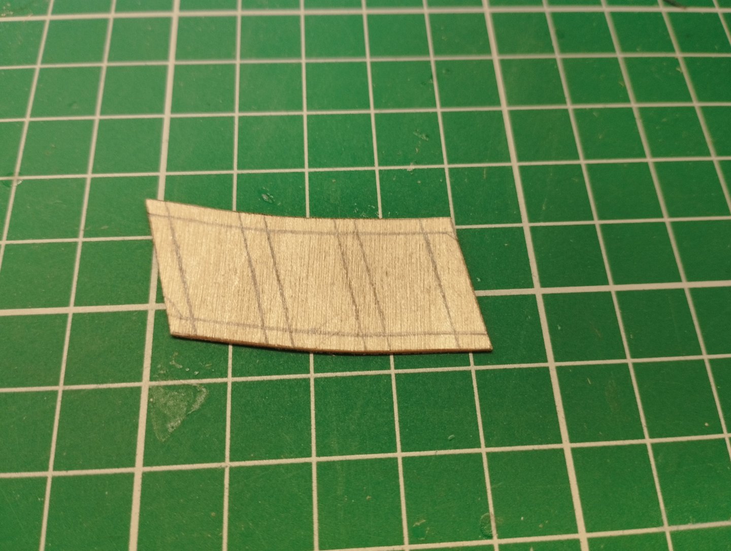
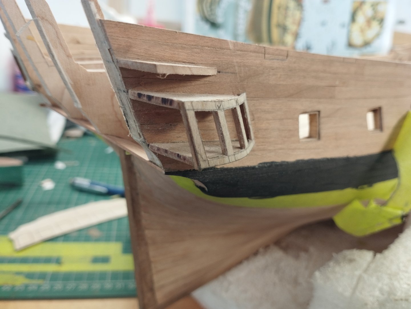
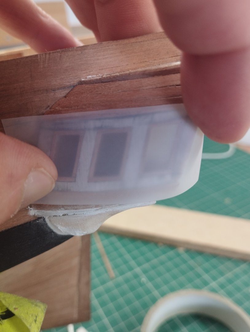
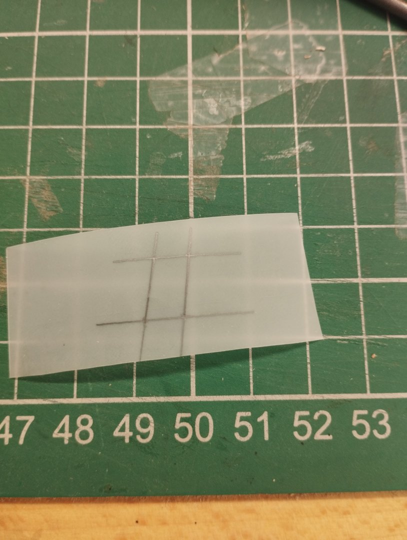
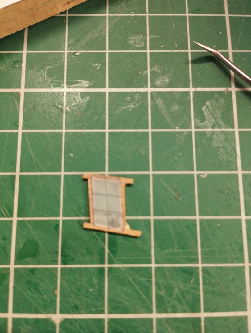
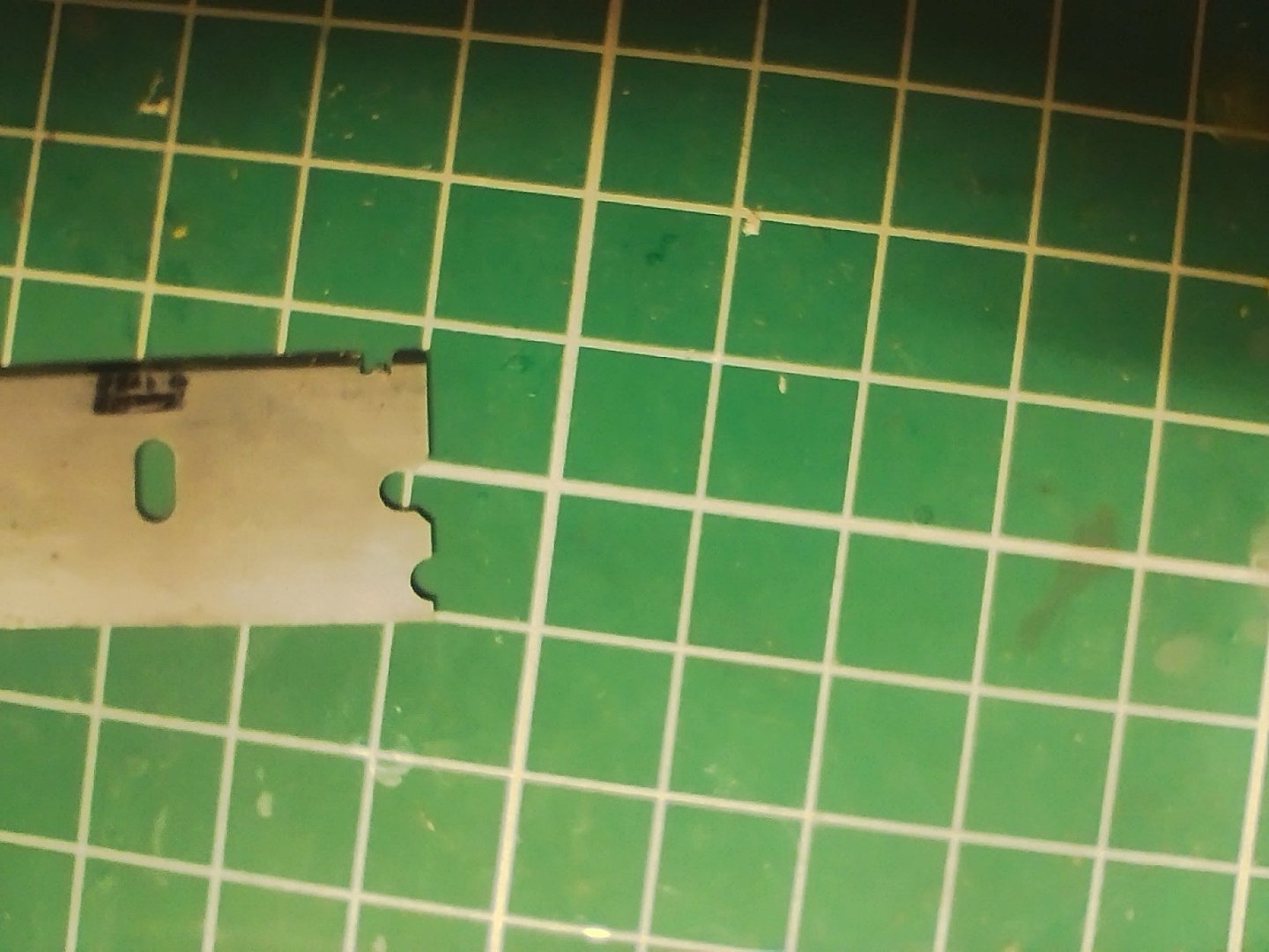
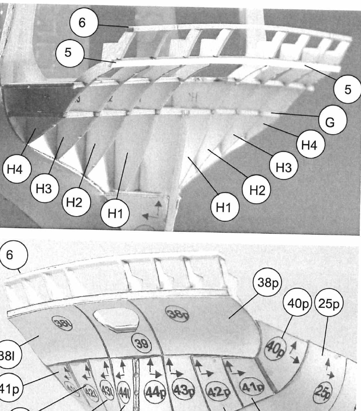
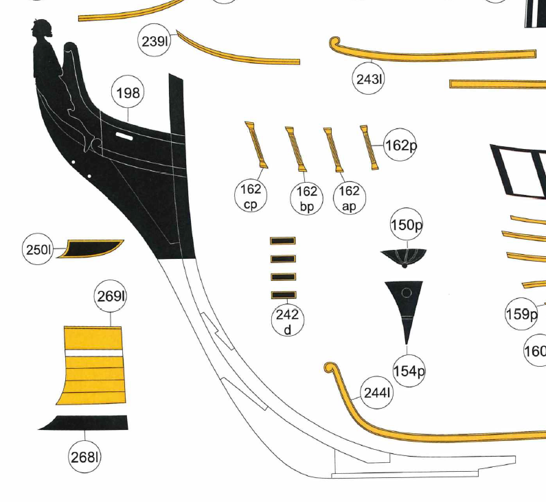
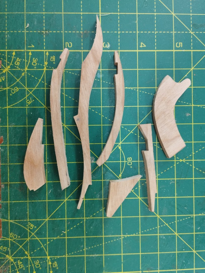
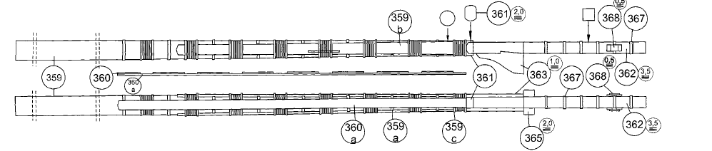
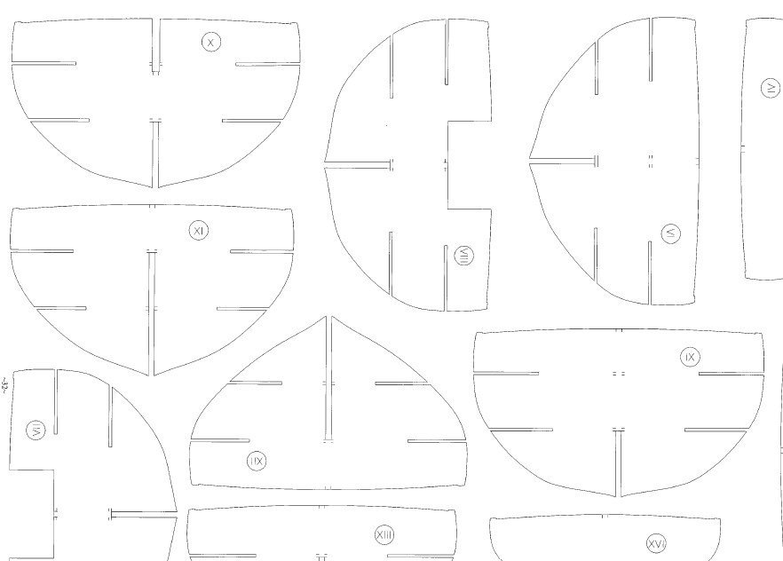
Hi All Must be time for an update. I've been working on the stern and quarter galleries and was hoping to combine these into one post but but time available will mean I split these into two. I'll concentrate on the quarter galleries in this one and show where I'm up to...generally I like to complete a section before posting but this is an update on where I'm at and is more of a work in progress than a finished piece of work. In all my models to date I've not had to deal with constructing quarter galleries so this was venturing into new territory. Using the parts depicted in the paper model for the formers (left photo) and the side template of the ship (middle) for placement and a pictorial view (right) on what it should look like The formers were made of 1.5mm cherry, simplified as I'm not showing any internals and glued to the side of the hull. Having no scale plans available it's critical to maintain reference points along the hull so that correct positioning of the hull template is maintained Next came the forming of the window frames using 1.5mm ply and the paper model parts as a guide I then used 1mm x 2mm cherry for the external window frames. Some planking was also completed at this stage aided by filler blocks between the formers Modelling the internal frames was more tricky and I'm sure there are far better ways of achieving a better result. Using see through film I marked the corners of the widows and drew the shape of the frame and cut this out double checking that the shape was a good fit Using this template I glued 1mm x 1mm cherry so that roughly half was overhanging the template, apologies the photo below is not the best but hopefully you get the idea Once the glue is dry it's then a matter of sanding the "external" wood back to the template and fine tuning to fit the window opening. I then used 1mm x 0.5mm cherry to make the individual widow frames (and I can't find any photos of this)....but if you imagine from the photo above that the lines marked are the actual pieces of wood then I first glued the vertical piece and then the individual cross pieces. This was all painted white and backed with black card an clear craft glue used to simulate glass (white glue would give the same result). Because I used 1mm x 2mm for the external frames this gave depth that allowed the internal frames to be set back a little to give some definition The rails were made from 1.2 x 1.5mm cherry and a simple scraper was made from a razor blade The making of the "bottom" of the galleries (not sure what this rounded part is called) which you can see in the right hand photo above required the use of 3 templates to get the required (or close to) shape and fortunately although not the intended purpose there is enough provided in the paper model to fashion this piece. Part 141 below is a former piece of the galleries Part 137 is the shape againt the hull and the blue piece is the shape that ties into the planking These were glued to a block of Jelutong and sanded top a shape (or at least what I thought was to shape) and glued to the hull and over the wales. If you look at a couple of photos above where I'm describing the marking of the external window frames this originally was quite chunky and required quite an amount of shaping to get a better look. It's far from perfect but I'm quite happy with the result and will look a lot better once painted. I'll leave it here for now and will follow up with a post on the stern area soon Thanks for dropping by Mark


-
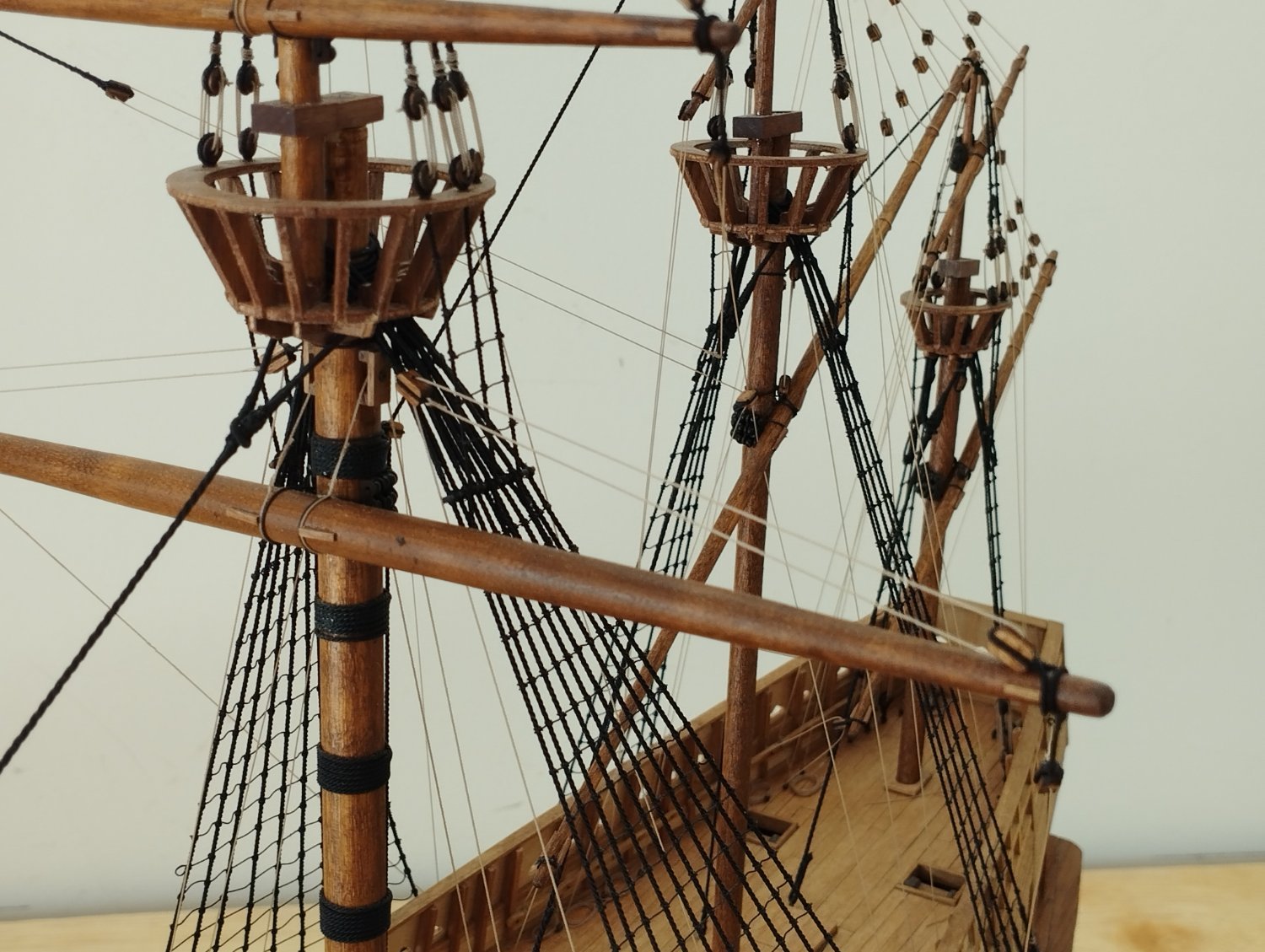
To help keep things stable I put a pin in the yard and drill a corresponding hole in the mast. Where the two meet I file them a little flat and then use a bit of epoxy to glue the two together. It's saved me numerous times as I've inadvertently knocked the yards when doing the rigging
-
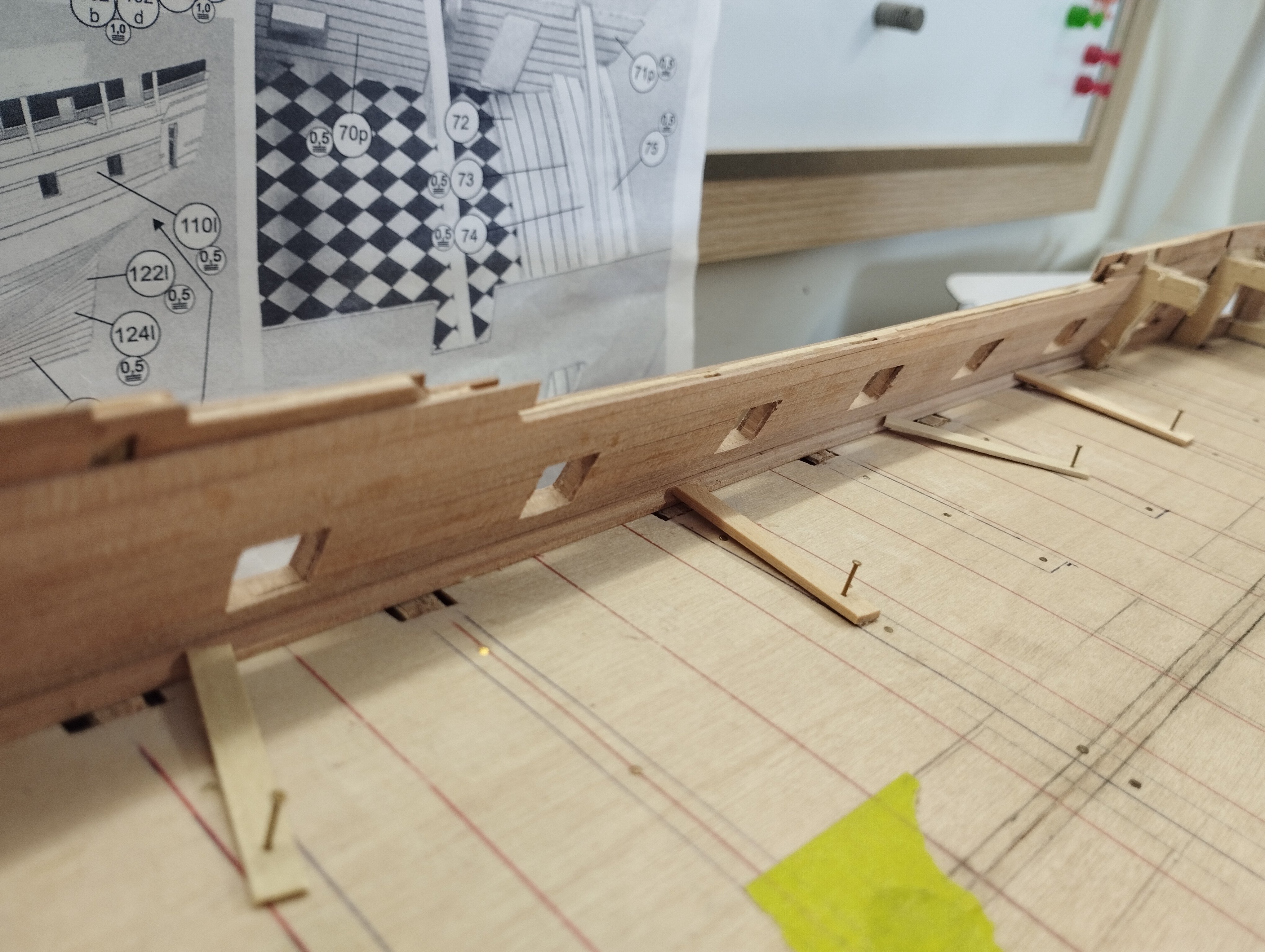
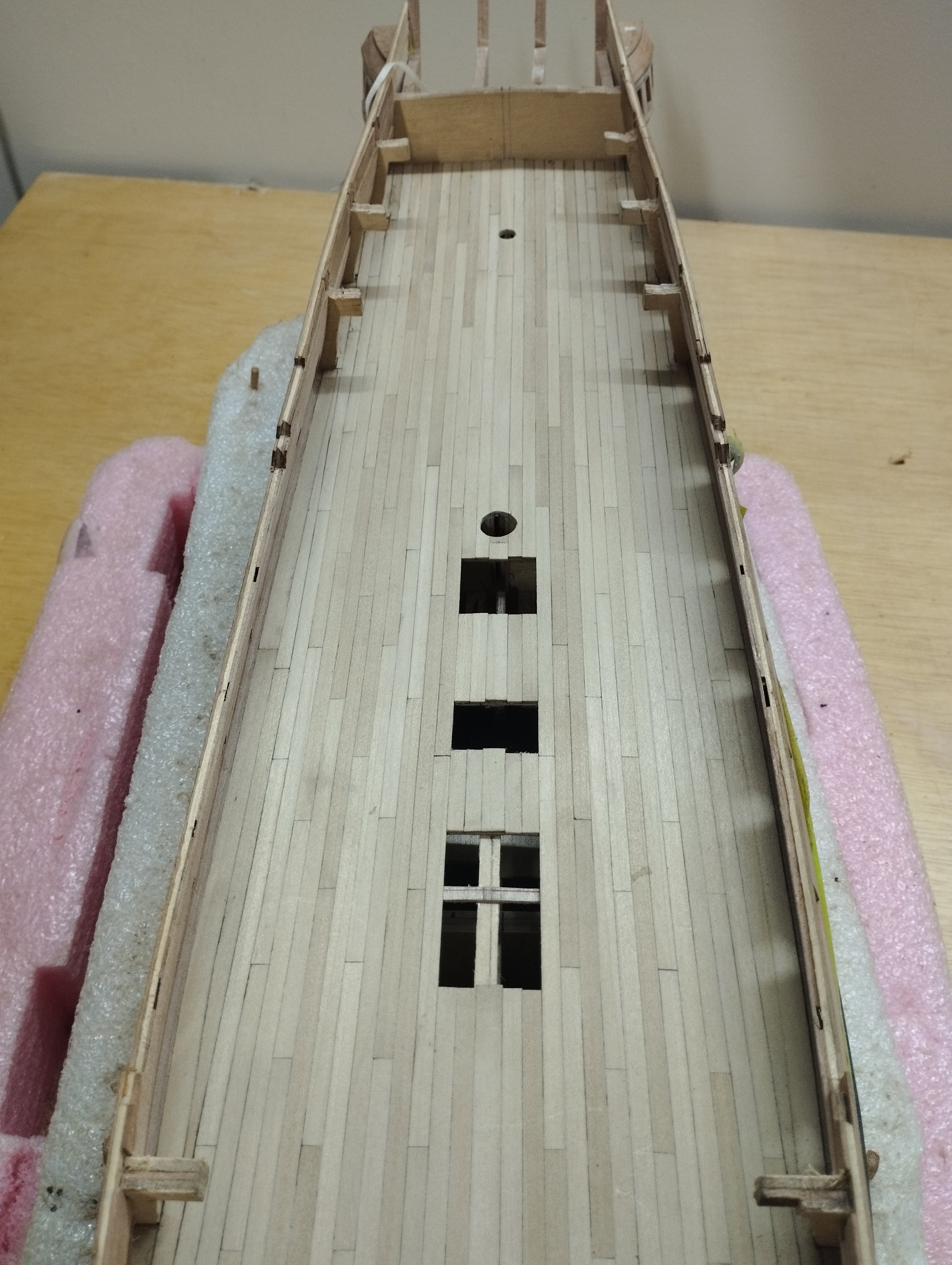
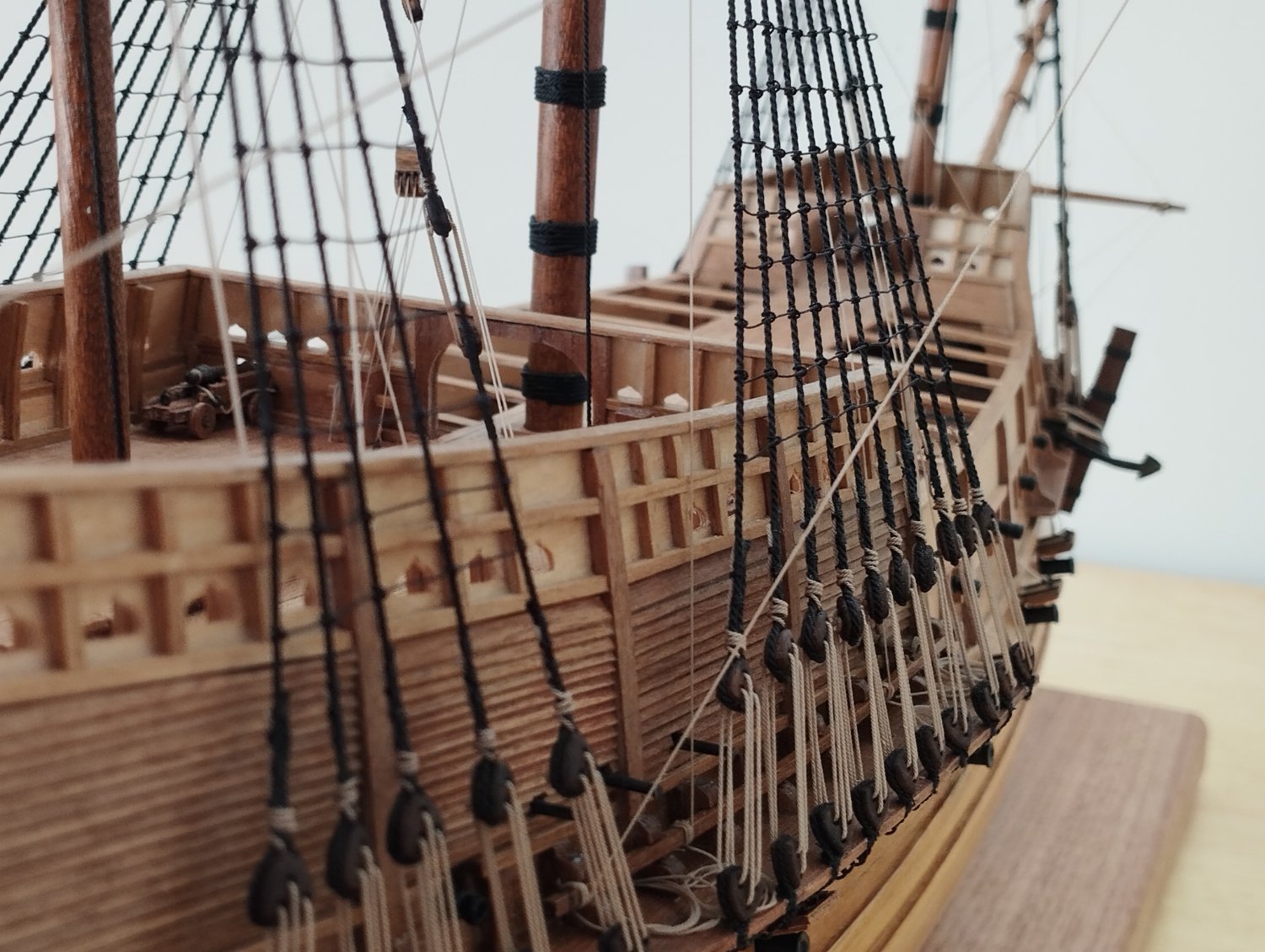
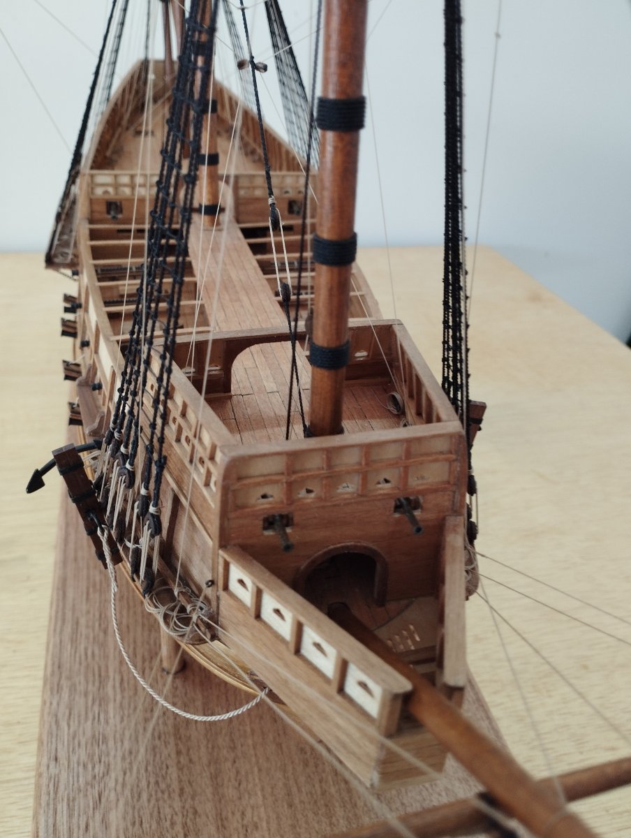
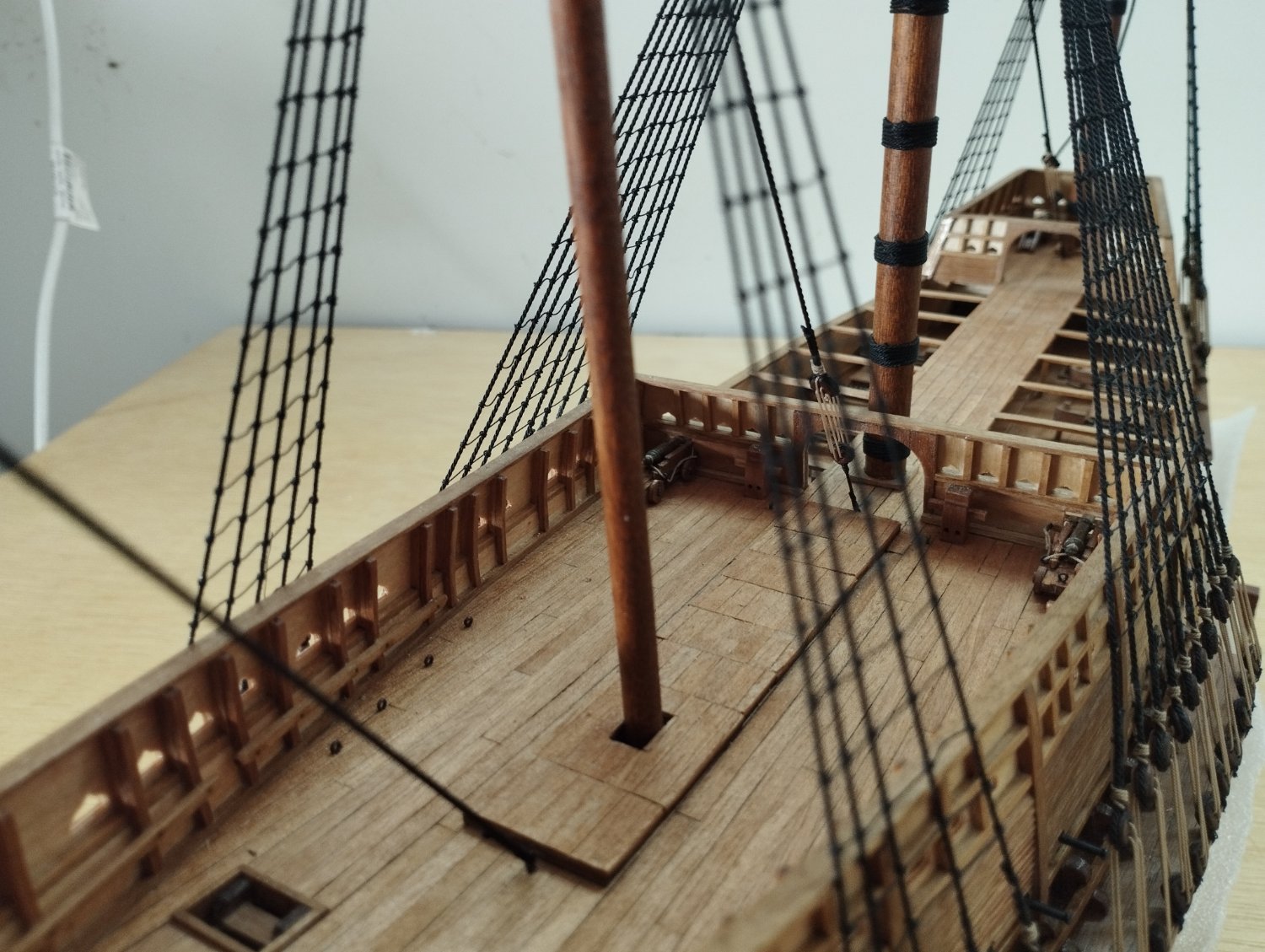
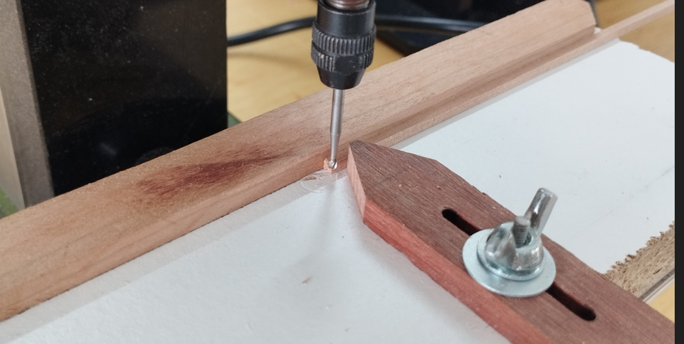
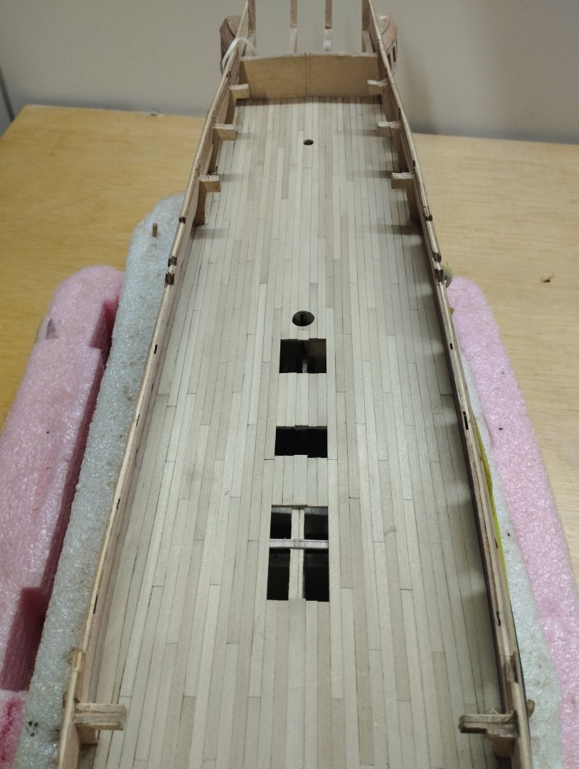
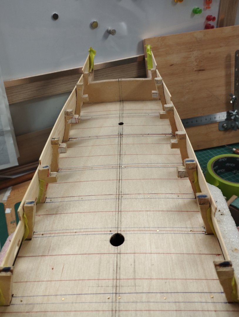
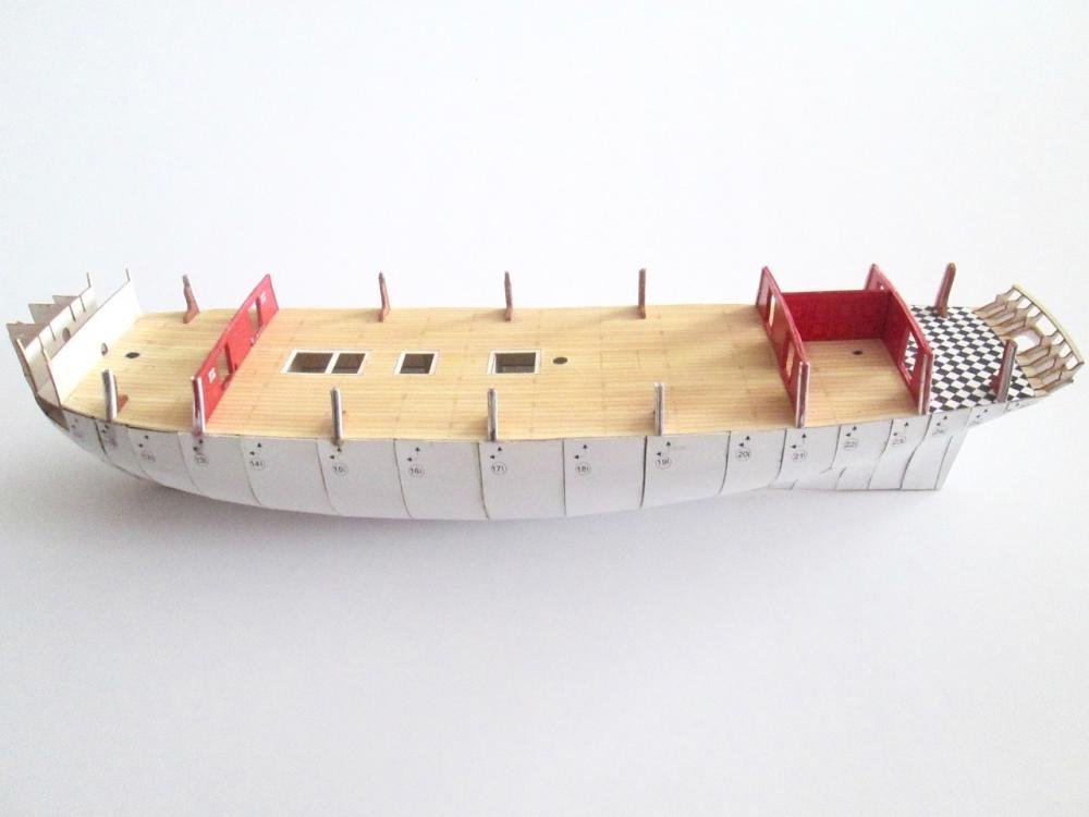
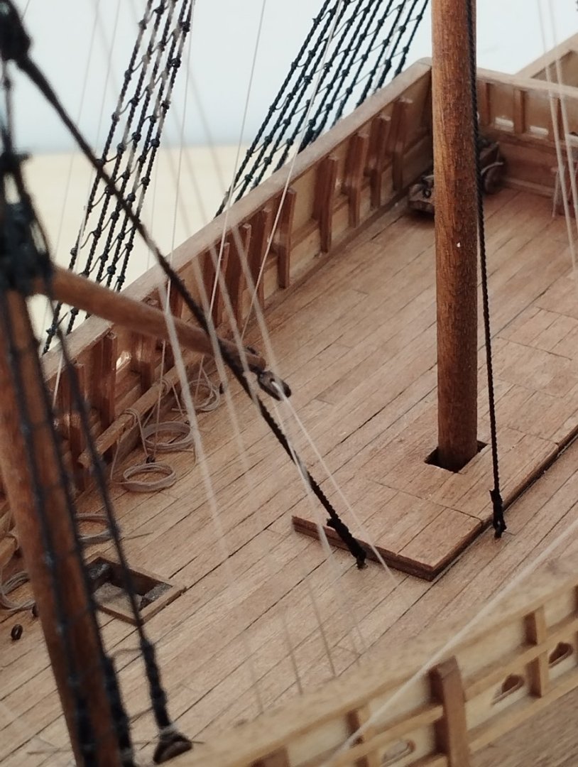
Hi All Quick up date to show planking of the main deck. Although the plans don't provide for a waterway I've modeled a basic version of those shown in Peter Goodwins reference book on the construction and fitting of a Sailing Man of War. Using a 2mm x 2mm length of cherry I ran this past a ball nose mill bit to provide the required profile. This took several passes to achieve the correct profile as I needed 1mm at the top and bottom of the concave shape The table fixed to the milling machine is simply a piece of melamine board with a fence glued to run the stock against. I also added a version of an adjustable "feather board" to help keep the stock tight against the fence as it passes the mill bit. The waterway was added to the false deck. I've removed the temporary bulkhead extensions discussed in post#1 and added additional internal planking to thicken the bulwarks. First was an additional 1mm of cherry that I had left over from the external planking and the final planking is 1mm of Tasmanian Myrtle and this will be left natural and not painted. Total thickness of the bulwarks is now 4.5mm I've cheated slightly in that the waterway is only fitted to part of the deck where it will be visible, I've not ran it the full length of the ship. I've used poplar for the planking. King plank and margin planks are 1mm x 6mm the rest of the planking is 1mm x 4mm. To represent the caulking I use a medium hardness charcoal pencil. A 4 butt shift pattern has been used The waterway is flush with the deck planking having allowed the 1mm and I've just got to add the spirketting which will be 1mm to fit against the top of the waterway Thanks for dropping by Mark

-
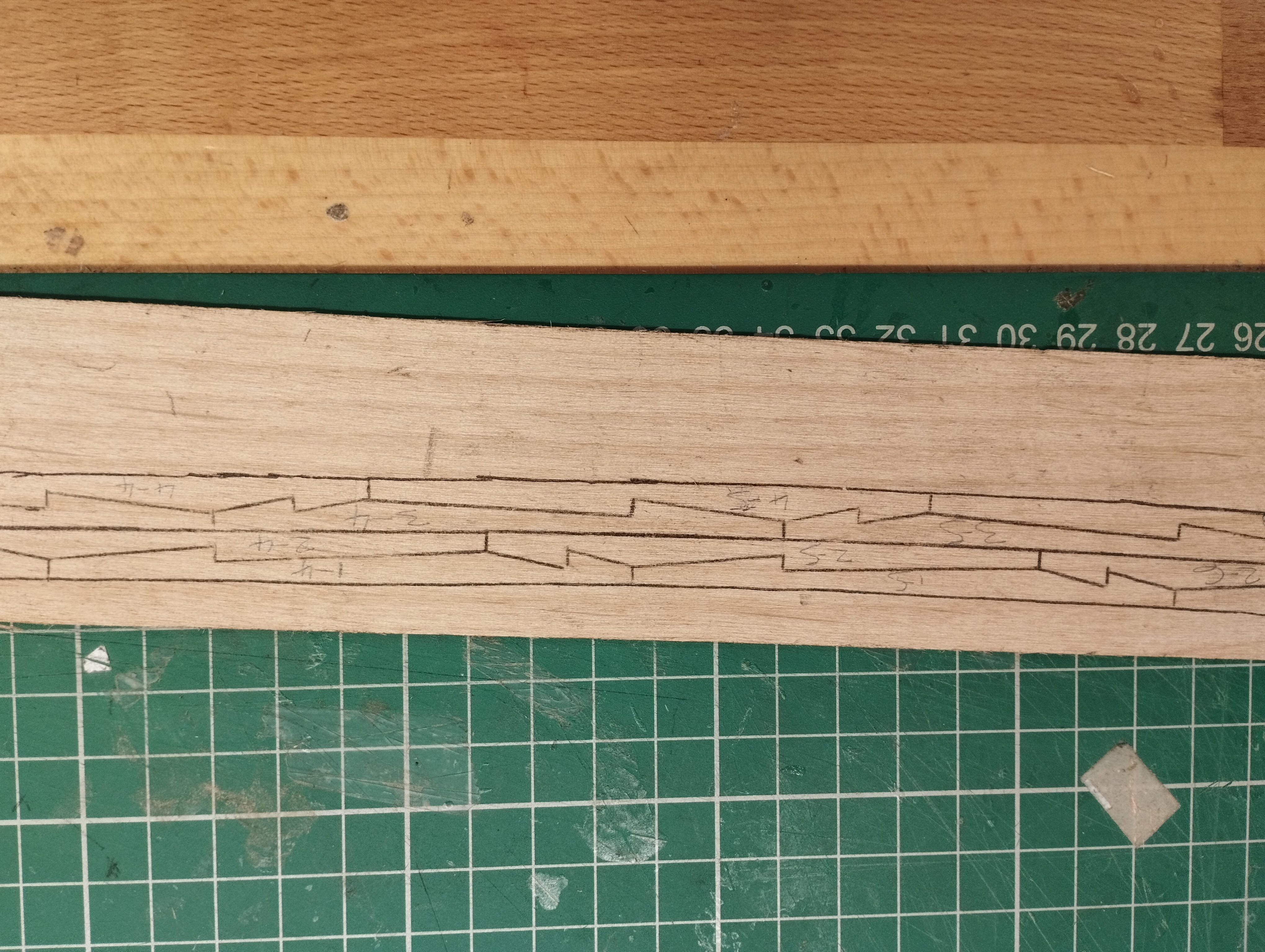
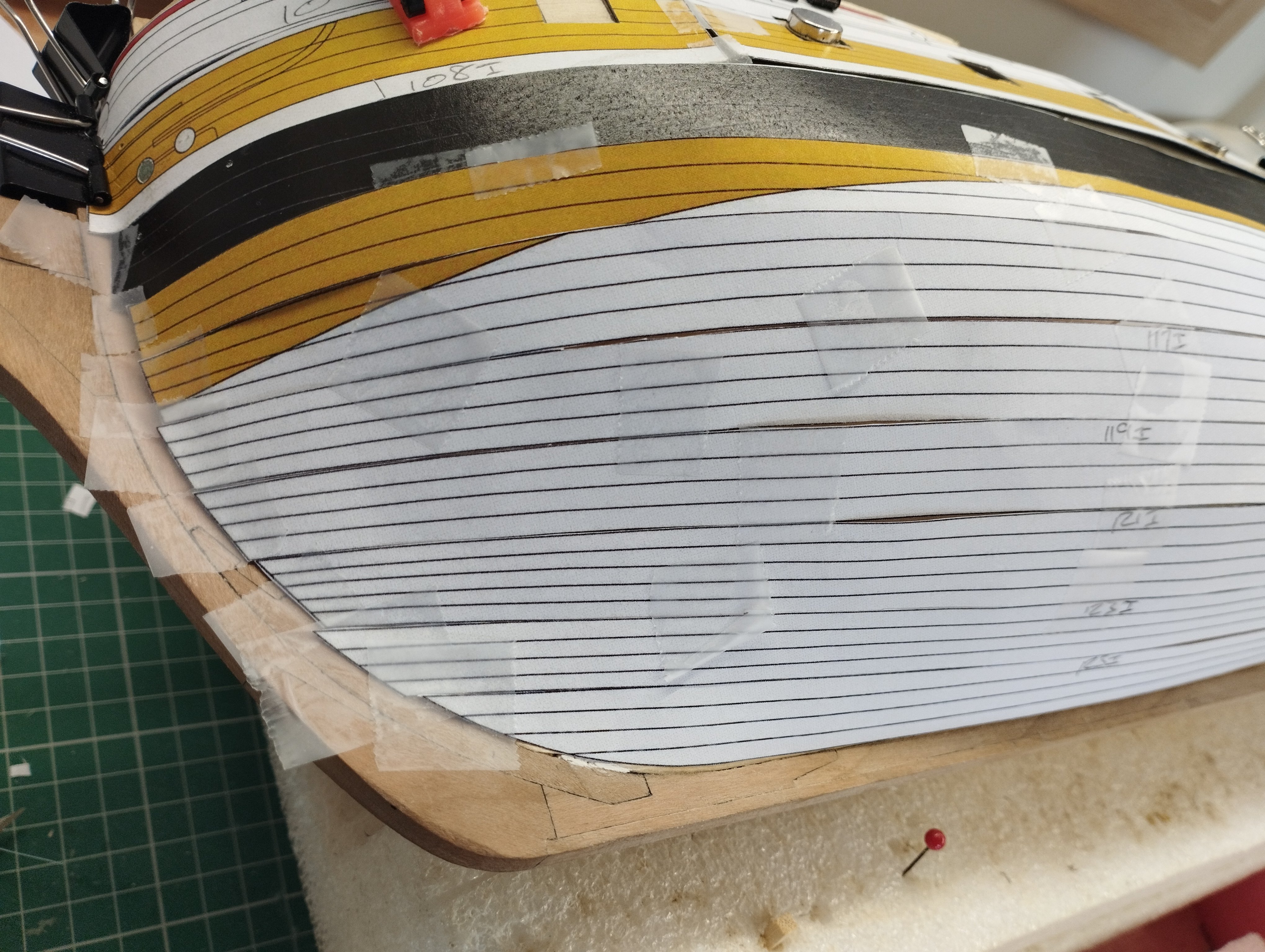
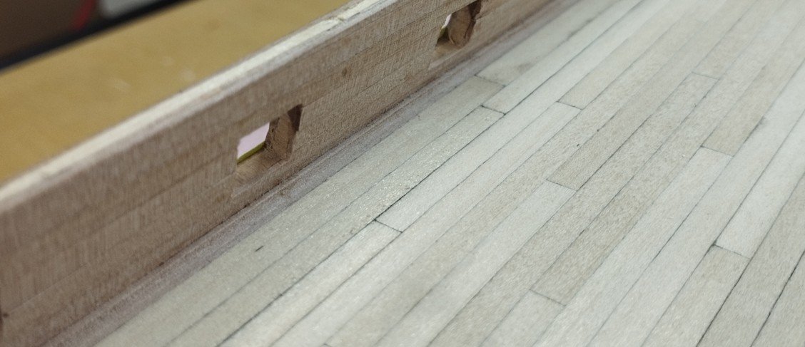
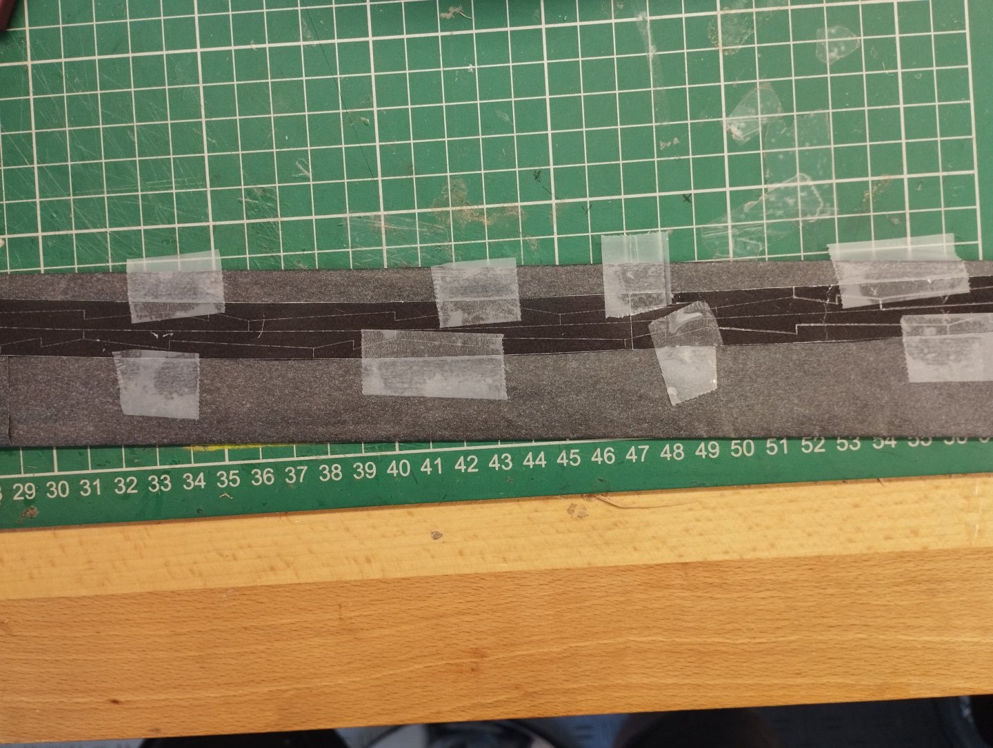
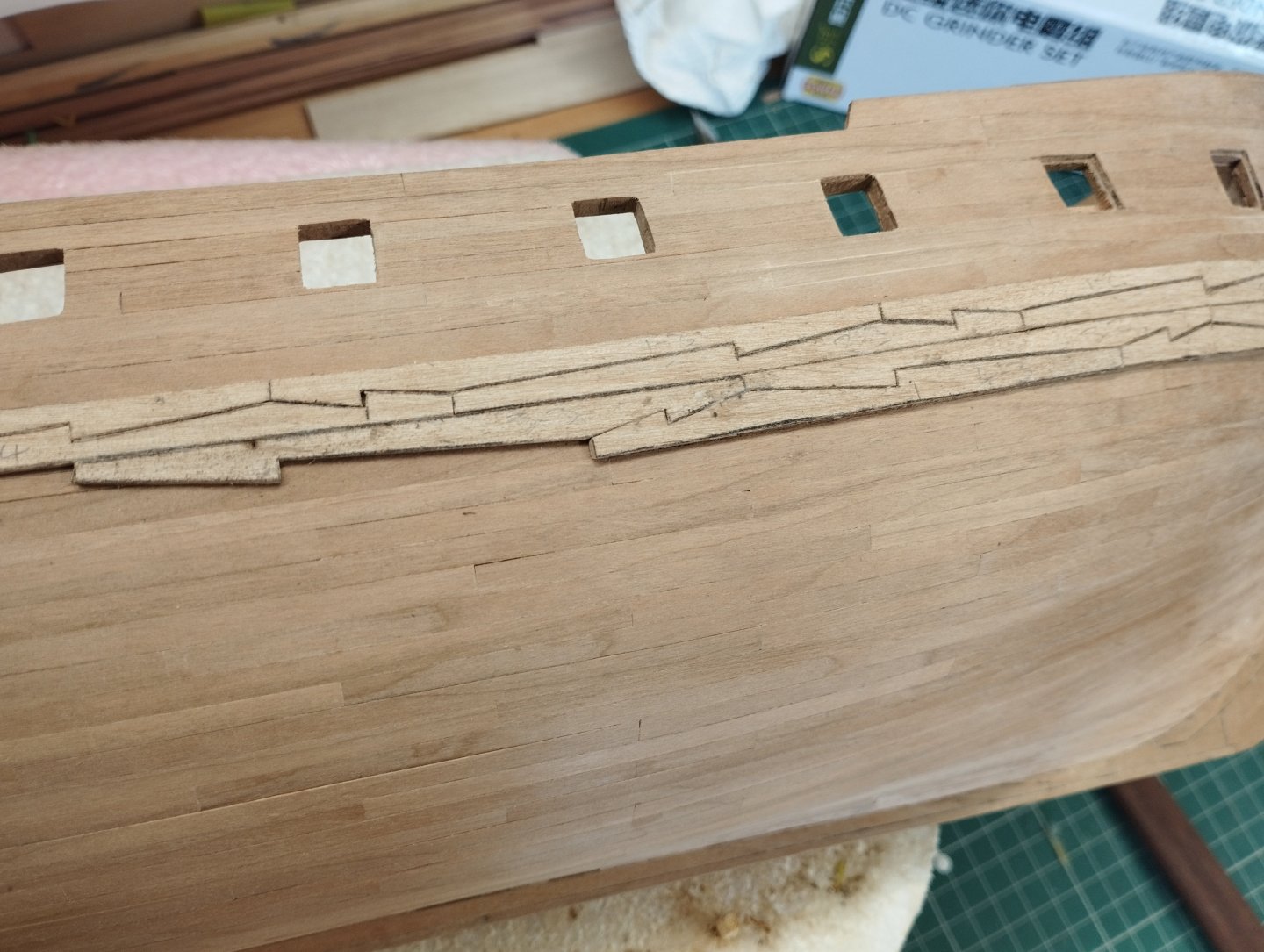
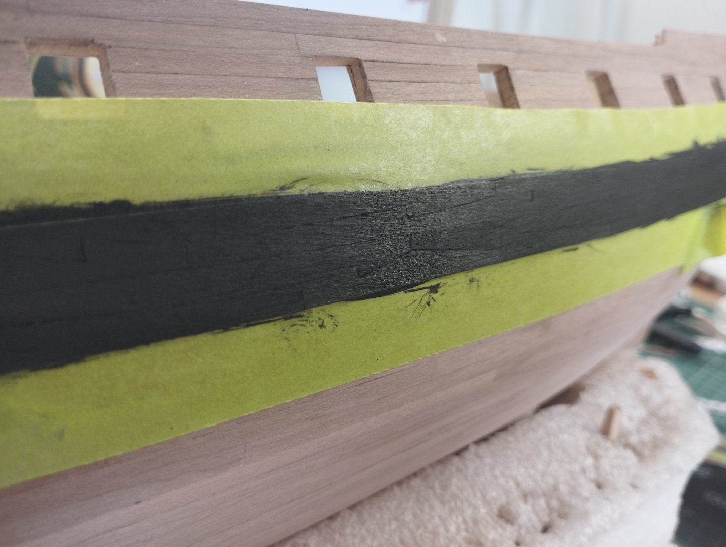
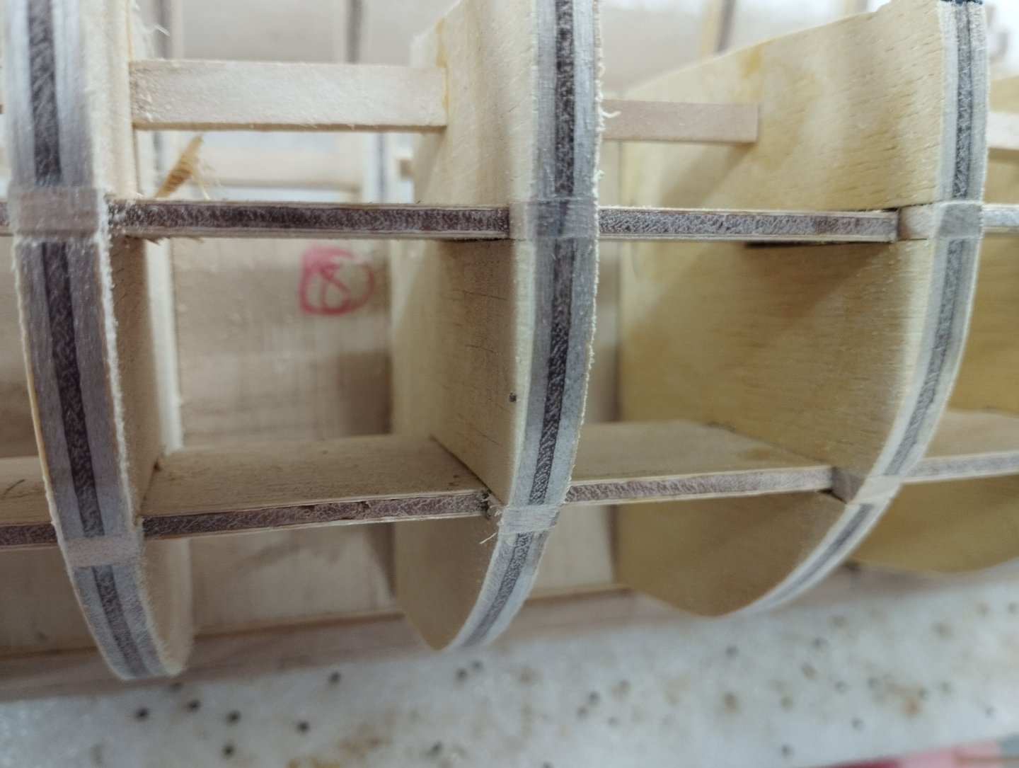
Hi All Thanks for the likes. Wales are now complete. The paper model simply has a paper template glued to a sufficiently thickness of card and stuck appropriately on the model. The template shows a hook and butt planking and I've used this to provide the shape of the planks for the wales I taped the template to some carbon paper and this was then taped to some Alder milled to 1mm. I used Alder for no other purpose than I had some deep enough (50mm) from stock that allowed the template to fit. The lines were then drawn over with a 0.3 mm pencil to provide the cuts required. The planks were individually numbered and cut out with a knife, below shows the work in progress Once complete I masked off the hull and used black wood stain to finish. I didn't use paint as I wanted to keep as much definition of the planking as possible seeing as how I had put the effort in. Masking tape will stay in place for the time being as I work on the quarter galleries and there is a further row of planking required just above the wales which I'll complete later. Thanks for looking in Mark


-
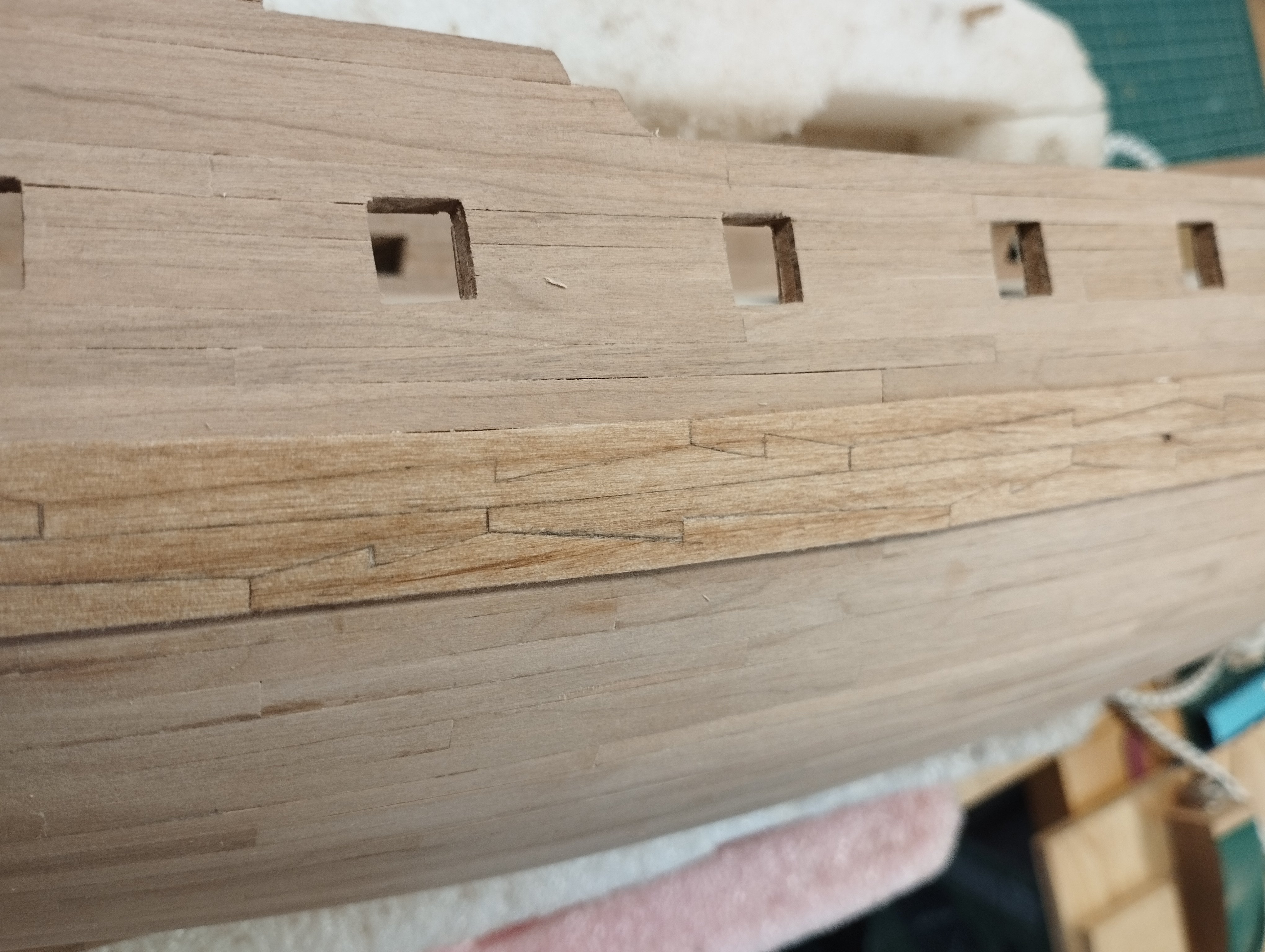
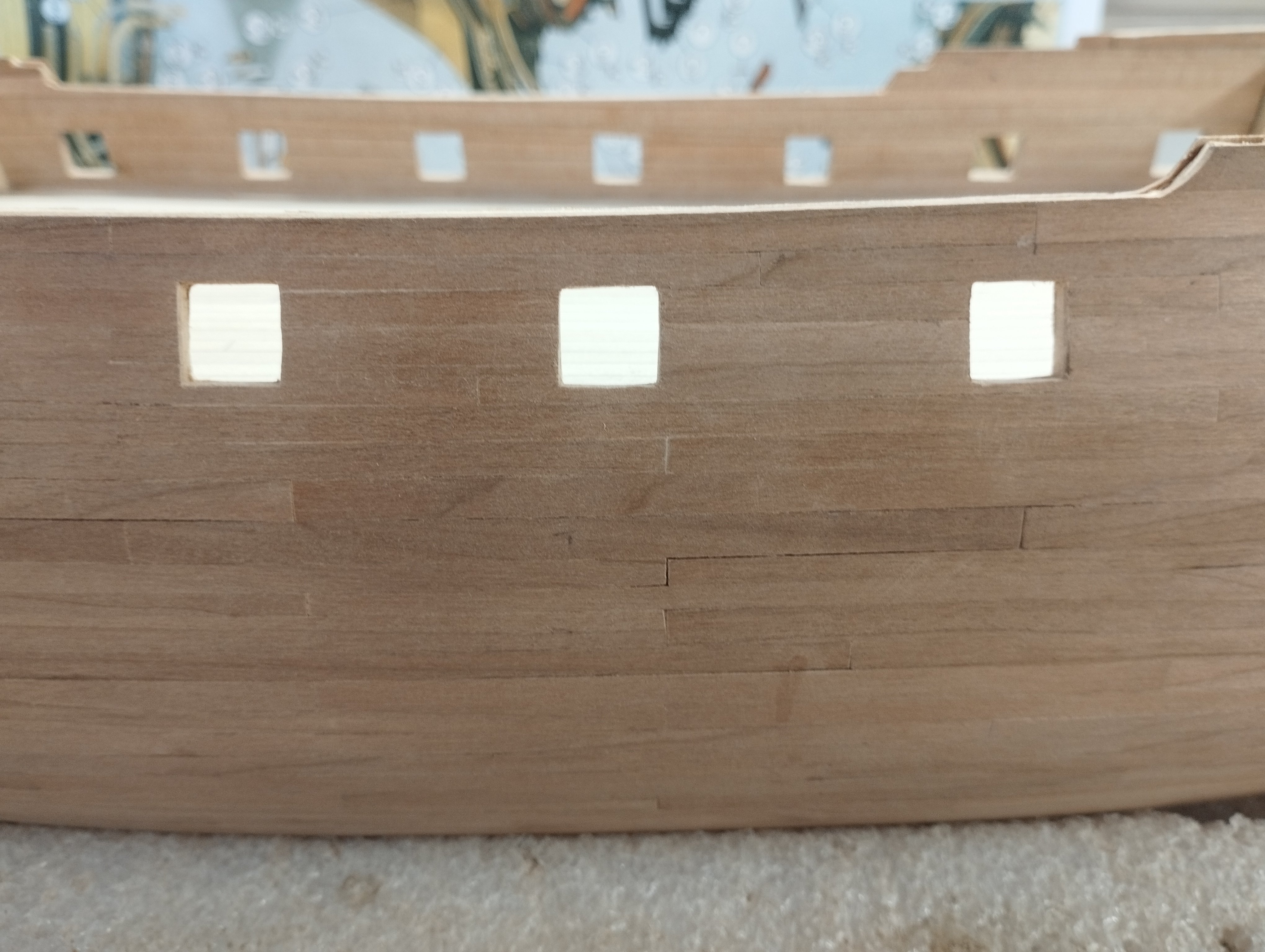
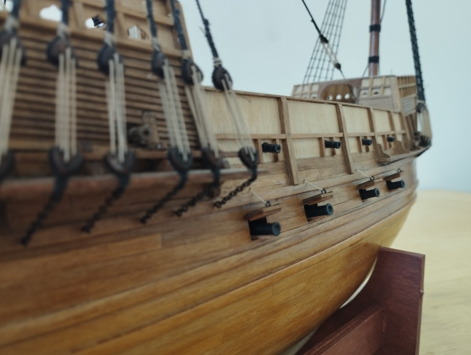
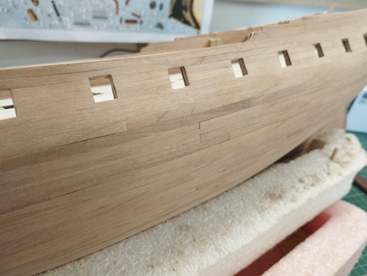
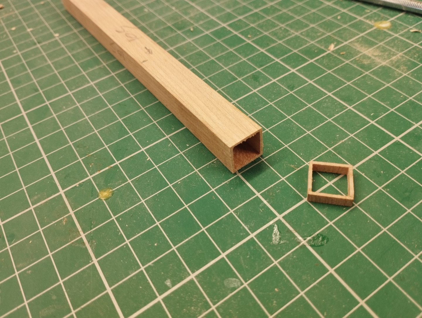
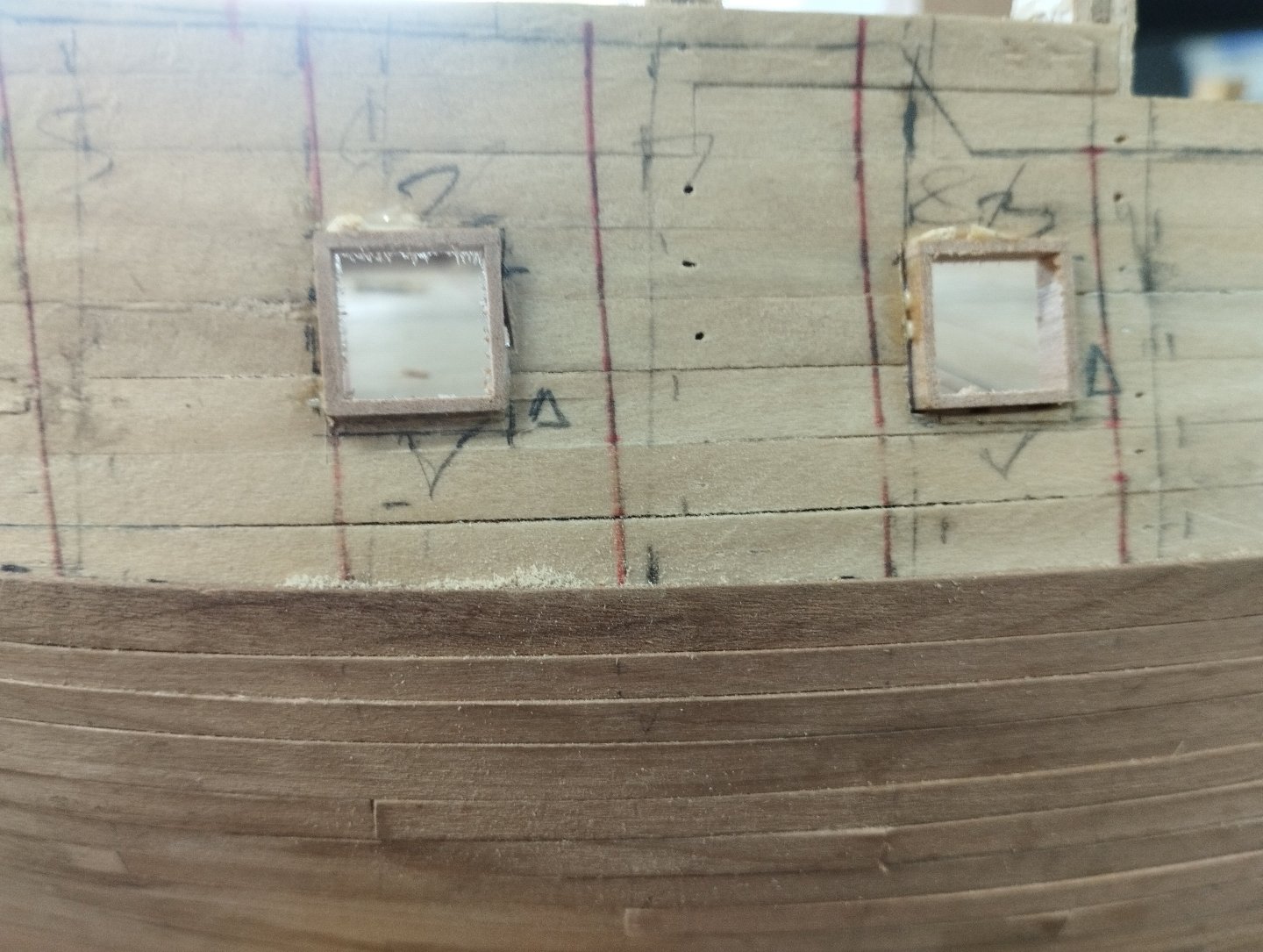
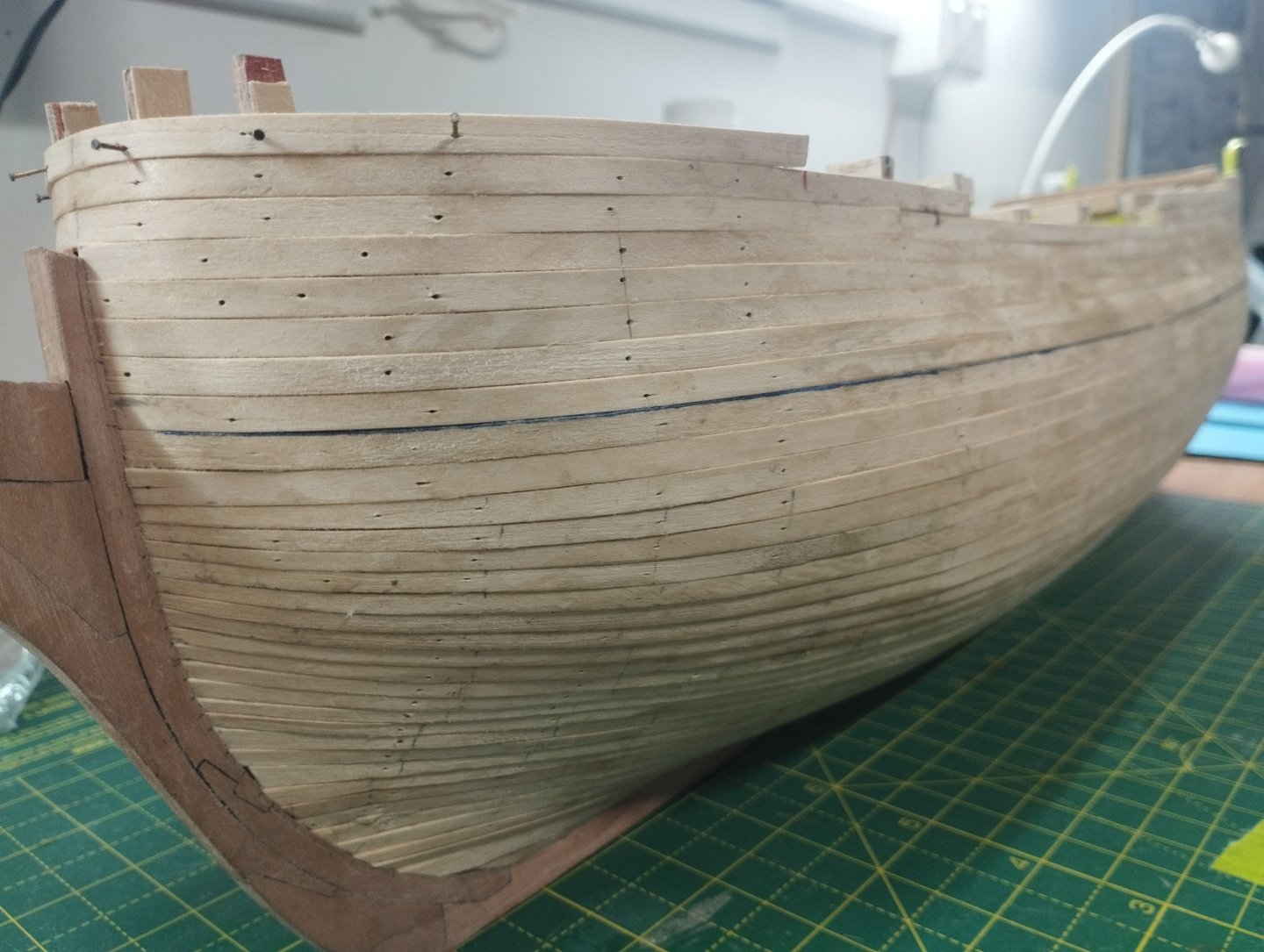
Hi All First things first....Happy New Year and hoping you all have a great 2025. Looking back at the date of my last post it's taken me 7 months to complete the second layer of planking - I envy those who can plank in a matter of weeks as it (obviously) to take me an age to do. This seems such a small update bearing in mind the effort Planking has been done with cherry at 4mm x 1mm and in 100mm lengths. I've used a 4 shift butt shift.....not sure if this is historically accurate but I like the pattern. I've a little work to do in finishing off and it needs a sand but the following photos show the progress Side view.....there are a few gaps 3-4 strakes below the gun ports but this was rough planking as they will be covered by the wales To ensure the ports were all the same size, I made a "tube" and sliced an appropriate length to go through all layers of planking (internal and external). First step was to create a former off the correct squareness and then used 1mm cherry to "plank" around the former Following shows the ports installed Just some more photos showing the planking Hopefully the next post won't be as long in the making Thanks for looking in Mark


-
Hi Gregg I bought this....see my unboxing post below Its useful for small jobs in hard to reach places, I use my own sandpaper with double sided tape as the supplied grits are too fine for wood work. Mark
-
Byrnes table saw - belt tensioning
Mr Pleasant replied to Mr Pleasant's topic in Modeling tools and Workshop Equipment
Hi Mark Thanks for this, I'll do this next time I have the saw out for use. Mark -
Hi All Is there a way to tension the belt? I was ripping some planks today at it sounded as if the belt was rattling against the belt guard. I removed the guard but there was no apparent way to apply more tension to the belt apart from lifting the motor on its hinge point. As a result I've chocked some wood under the motor and this has solved the problem. Anyone know a better way? Thanks Mark
-
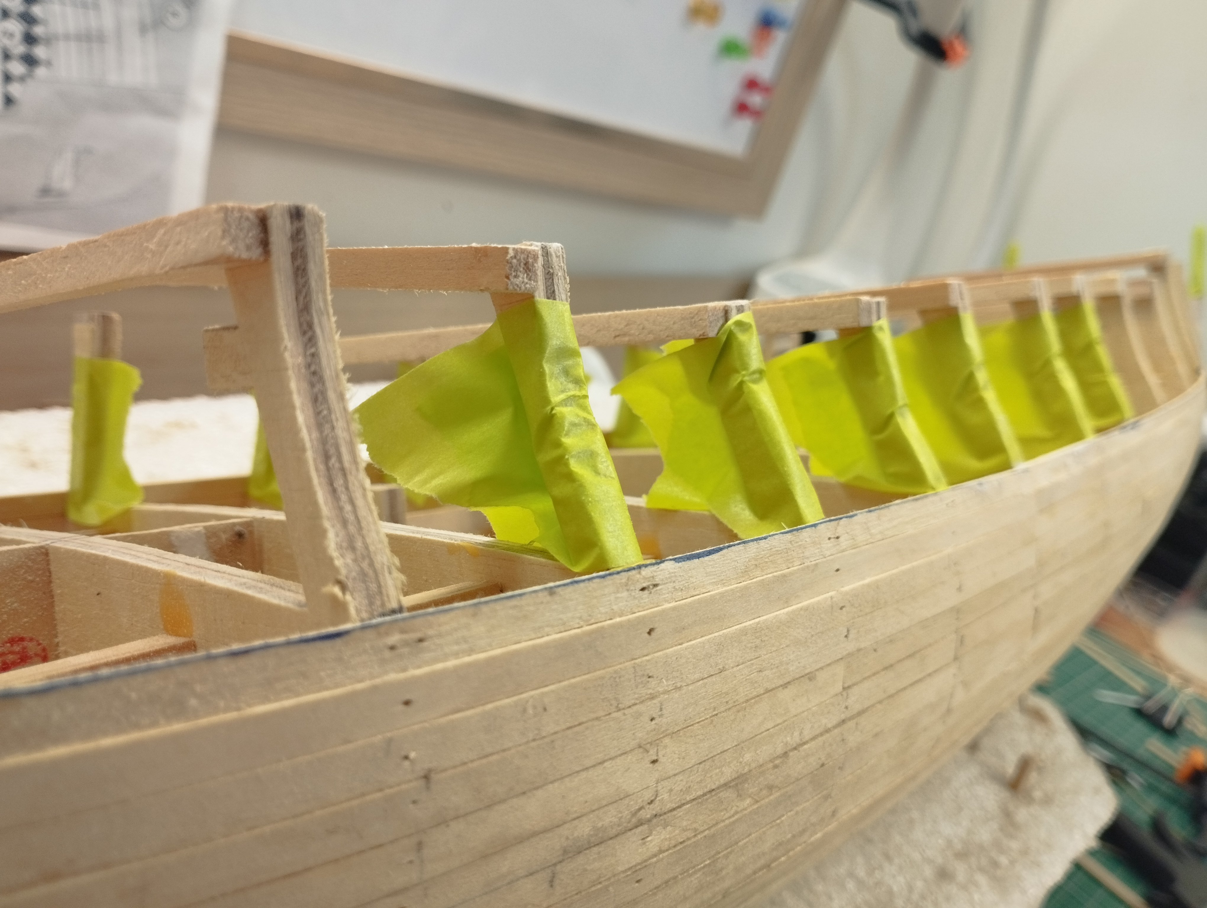
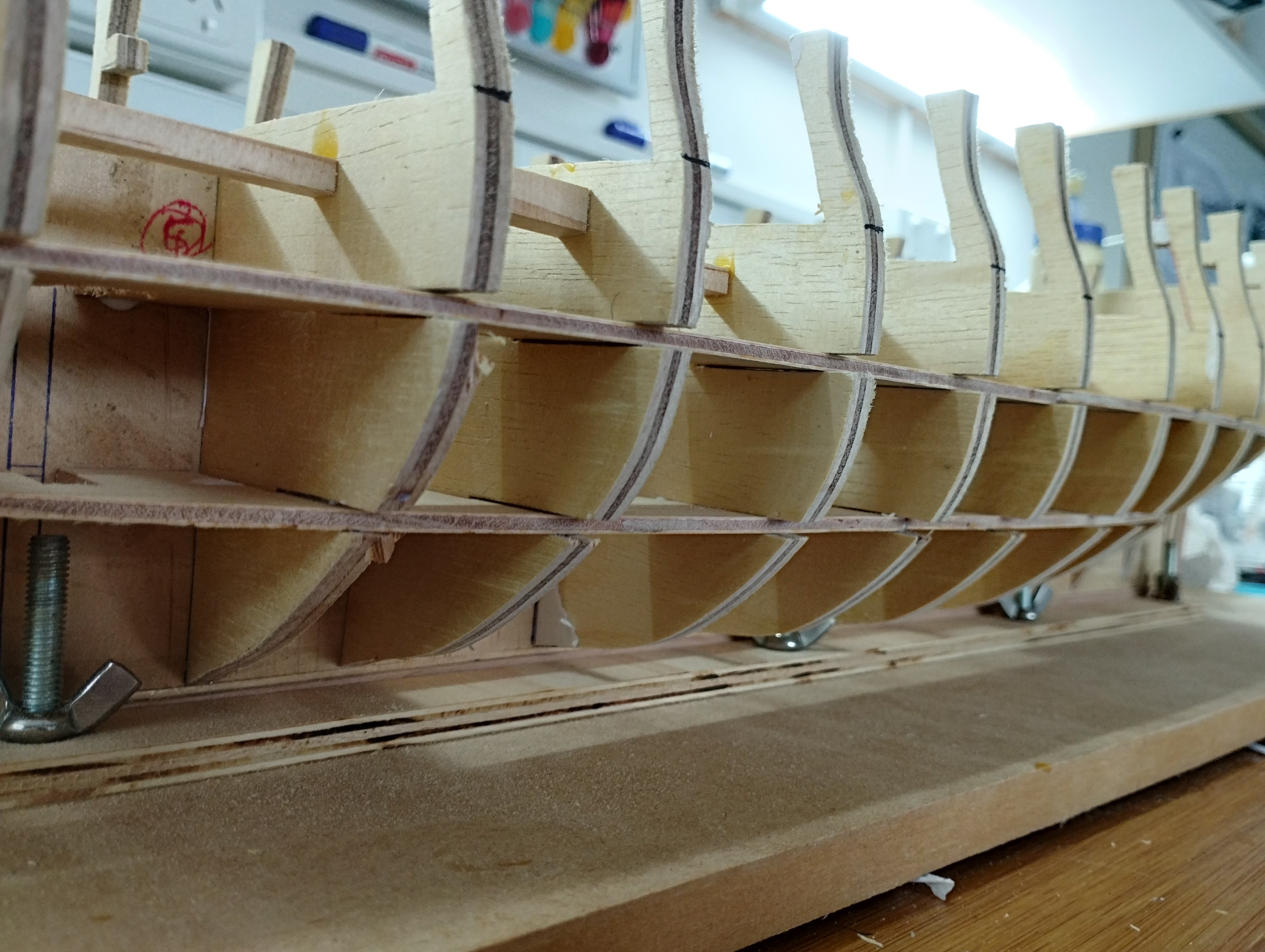
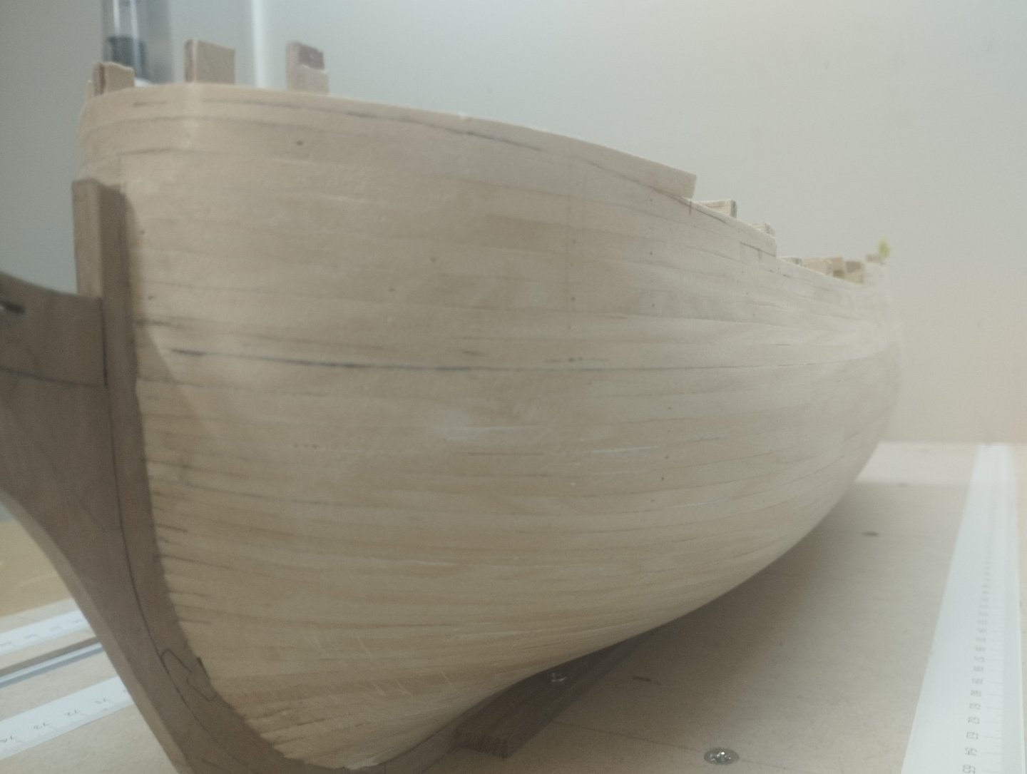
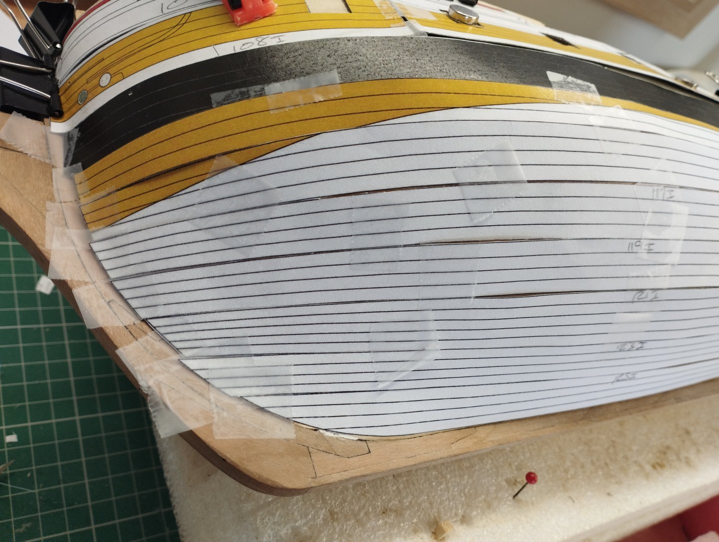
Hi All Thanks for the likes....time for a quick update. First layer of planking is now complete, below shows a bit of the progress, rough finish and after sanding. I placed tape around some of the bulkheads where I didn't want the planks to adhere to as these bulkhead extensions are to be cut away in future. I could have used templates to cut the bulwarks out of some ply but I've elected to plank instead. I also added some strengthening across the bulkhead extensions to protect and reduce the risk of them breaking them during planking. I used hoop pine for the planking and milled to 5mm x 1.5mm strips. Hoop pine has no discernable grain and bends quite easily....most importantly it stays straight after been cut into strips from a larger plank The planking turned out relatively ok, however, for transparency.....I did make a slight error. In the previous post I mentioned that I'd fair the mdf that I added as packing, which I did. What I didn't do was fair the "leg" above this and this has resulted in a run of concave planking for 5 or so planks. This will be hidden by the galleries but leaving like this will make it awkward to shape the formers of the galleries so I'll fill and sand this gap to get a straight run Fashioned a bit of a mast step glue well for all three masts as the 3mm spine would not give enough surface to glue onto. I know some people just rely on the rigging to keep the masts upright....but not me , more glue the better, no way am I relying on my rigging to keep anything straight As a quick check on how accurate I am at this stage to the paper model, I overlaid the paper planking templates onto the hull and all appears ok. Normally I would line off the hull for the second planking by working out the bands but as things look ok, I'll use the templates to give the bands and tweak as I go along (you can just make out the separate planking templates by the numbers I've written on them) . At the top you can just see the templates that could have been used to cut bulwarks out of ply And finally I added the false deck for the main deck. A joggle stick was used to shape the false deck and cut from 0.8mm ply. I had to install in separate pieces as I couldn't get it into place in single go. Holes cut (not vey well but sort of round) for the masts. I've marked the deck at every 20mm to help with the planking shift pattern Thanks for dropping in Mark


-
Use a piece of thin card or paper say 10mm in width. Stand it on its edge and form it around the bow area along your red line and mark the start and finish points. This will give the length of the space that you need to fit the planks to. Divide this length by the number of plank runs required at midship bulkhead (or however you've determined the number of planking runs required) this will give you the width of the blanks at the bow. Mark
-
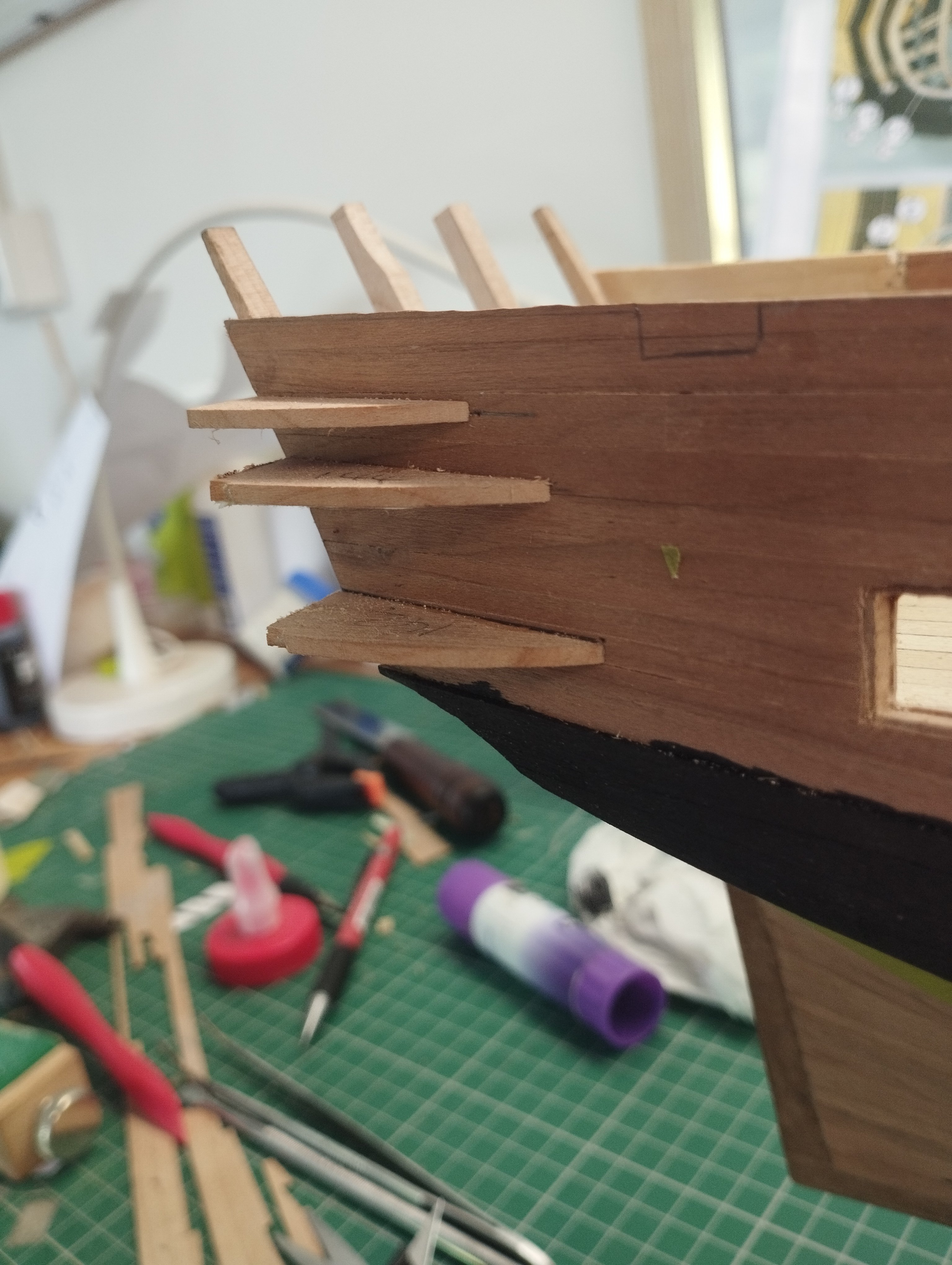
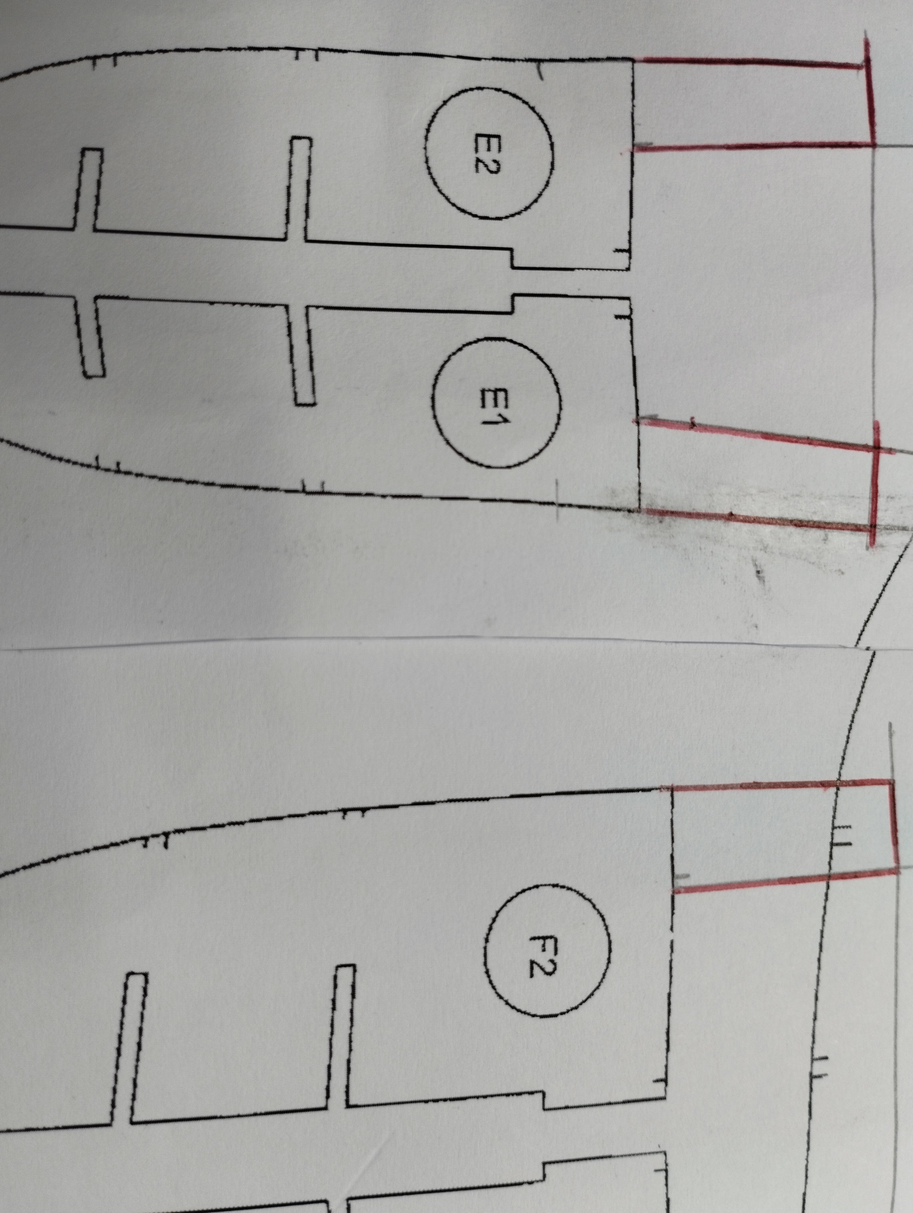
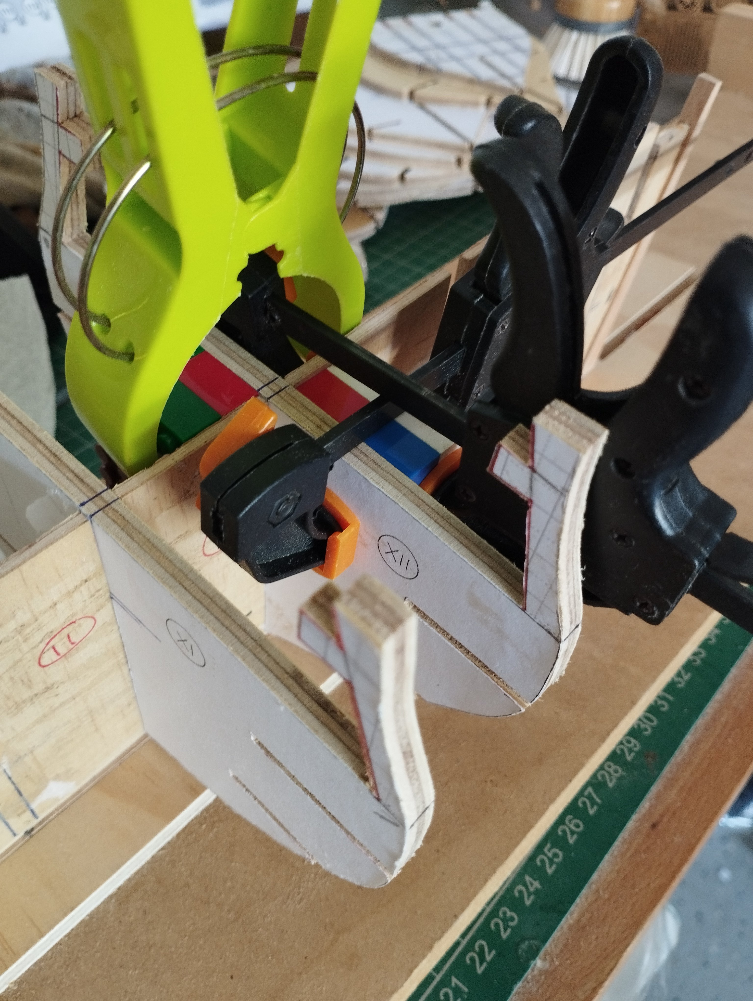
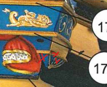
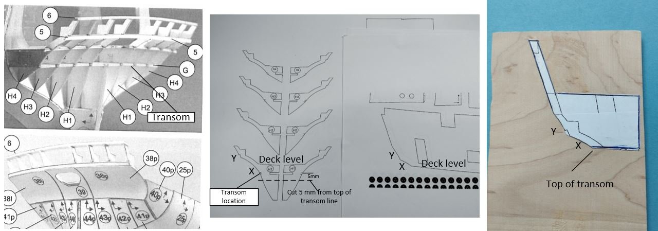
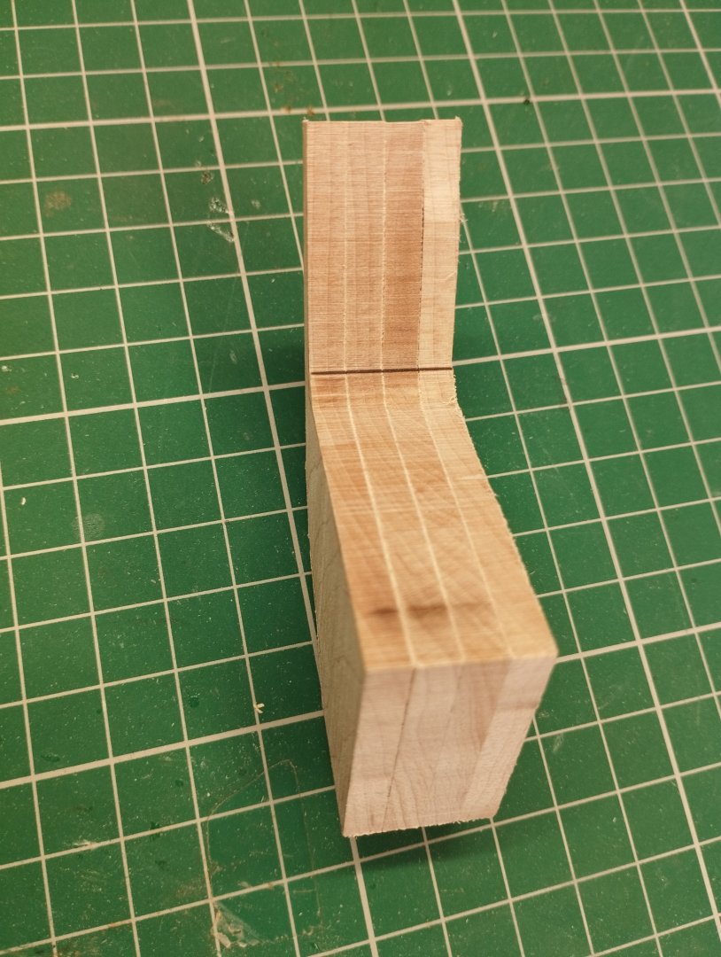
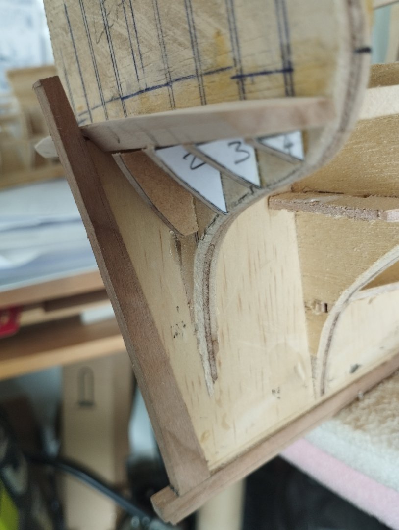
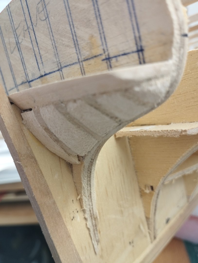
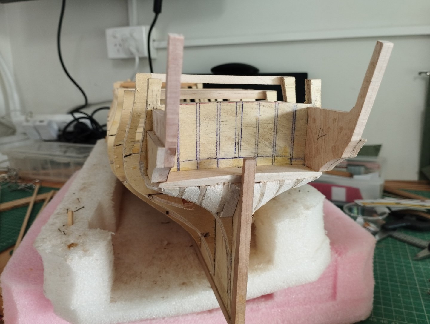
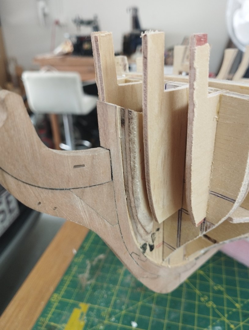
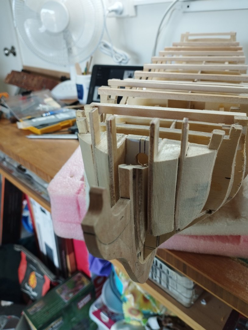
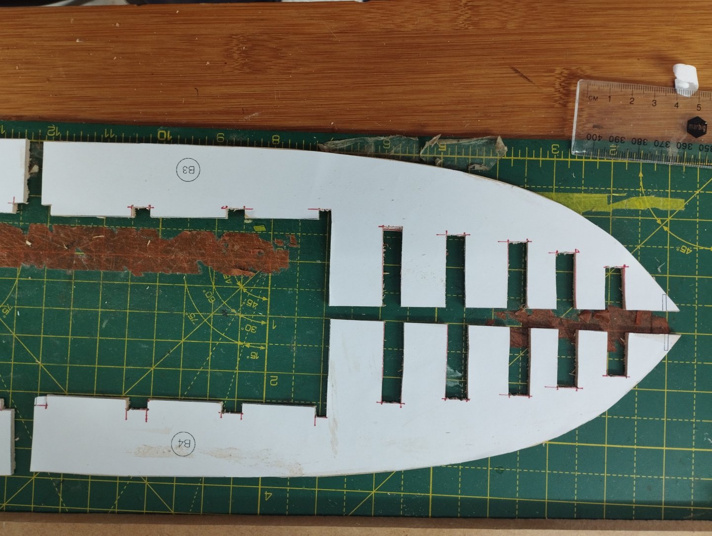
Hi All Thanks for the likes... Moving onto the stern area, this needed some manipulation to how the paper model is constructed. Hopefully my explanation of how I achieved this is not to confusing. Firstly for context this is how the paper model is done This formation allows for the modelling of the internals and for a moment my ambition threatened to overrule my ability, eventually, however reality prevailed and I decided against going this far. This means I have to change parts H1 to H4 (top left) to accommodate the fixing of the stern fascia. The paper model simply has this glued on top of part 6 (top left) and to the bulwarks and relies on the flexibility of the card to get some curvature. Although there are no corresponding parts to what I need to achieve, there is enough information provided for me to fashion the parts needed and this explained (hopefully) below Part G (above top left) is the transom and this was fashioned out of some hard maple 5mm thick by the template provide in plan view and the curvature determined by the markings on bulkhead 17 (horizontal markings). A chamfer was then created for the planking Next was extending parts H1-H4 to allow the forming and fitting of the stern fascia at a later date. To achieve this I used common features of two templates to give me the final shape Middle picture above....X, Y and the deck level are common on the formers H1-H4 and to the bulwark templates. These were glued one on top the other to produce a single template shown in the right. Blanks were then cut from hard maple using the template ...I'm only using H1 and H4 on both sides of the stern post and omitting H2 and H3 The only difference in the finished parts of H1 and H4 is the length that attaches to the transom to give the curvature of the stern fascia and this was cut to the correct size H1 and H4 templates were then used by subtracting 5mm for the transom to give me the shaping for the planking below the transom. Below shows these fitted and then filled with balsa and shaped Finally H4's are glued in place, with a bit of additional padding (3mm mdf) to help with the run of planking. This will be sanded for a fair line. I'm not installing the H1's at this stage as they will interfere with the planking Hope this all makes some sort of sense. Thanks for looking in Mark
-
Byrnes Saw for sale in the UK
Mr Pleasant replied to Some Idea's topic in Modeling tools and Workshop Equipment
It sold for £1020 which is roughly US$1300 and the thicknesser sold for £445. For comparison the saw was US$520 in July last year when I bought mine. -
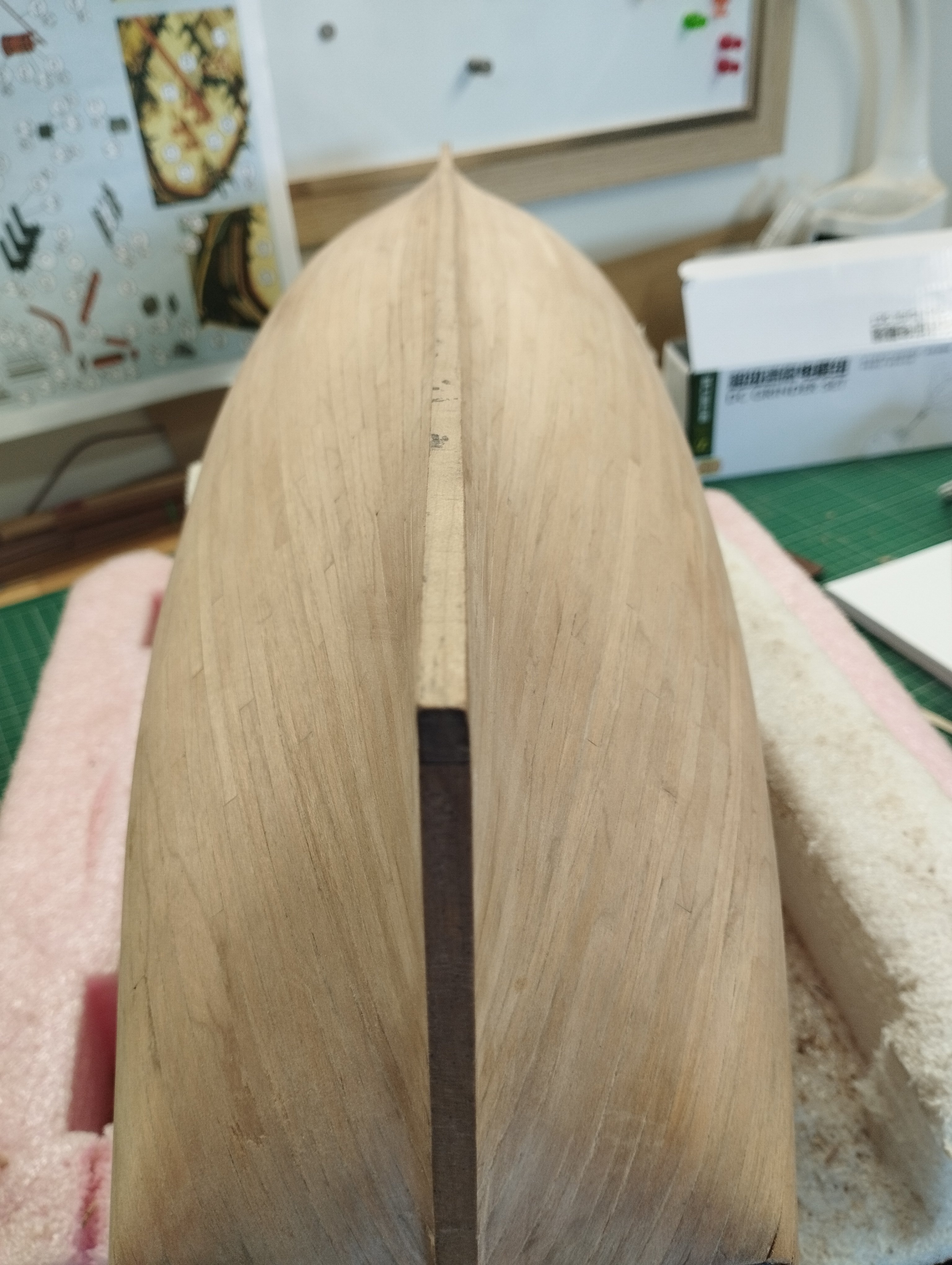
Hi All Thanks for the likes.... Just a quick post setting out the bow area for planking. This isn't the way I've done it in the past but seeing as how I'm experimenting in how I can use a paper model as the basis of a wooden version I've stuck with the way the paper model is done. From left to right shows the process First I extended the formers (red lines) above the deck level with sacrificial tabs to aid in the planking around the bow above the level of the deck Next shows them fitted and I've added some 6mm ply against the spine that follows the curve of the stem post and in line with the rabbet piece i fitted in post #1 Finally I've filled between the formers with Jelutong wood. This sands quite easy but takes nails better than balsa should I need to More functional than pretty Thanks for looking in Mark

-
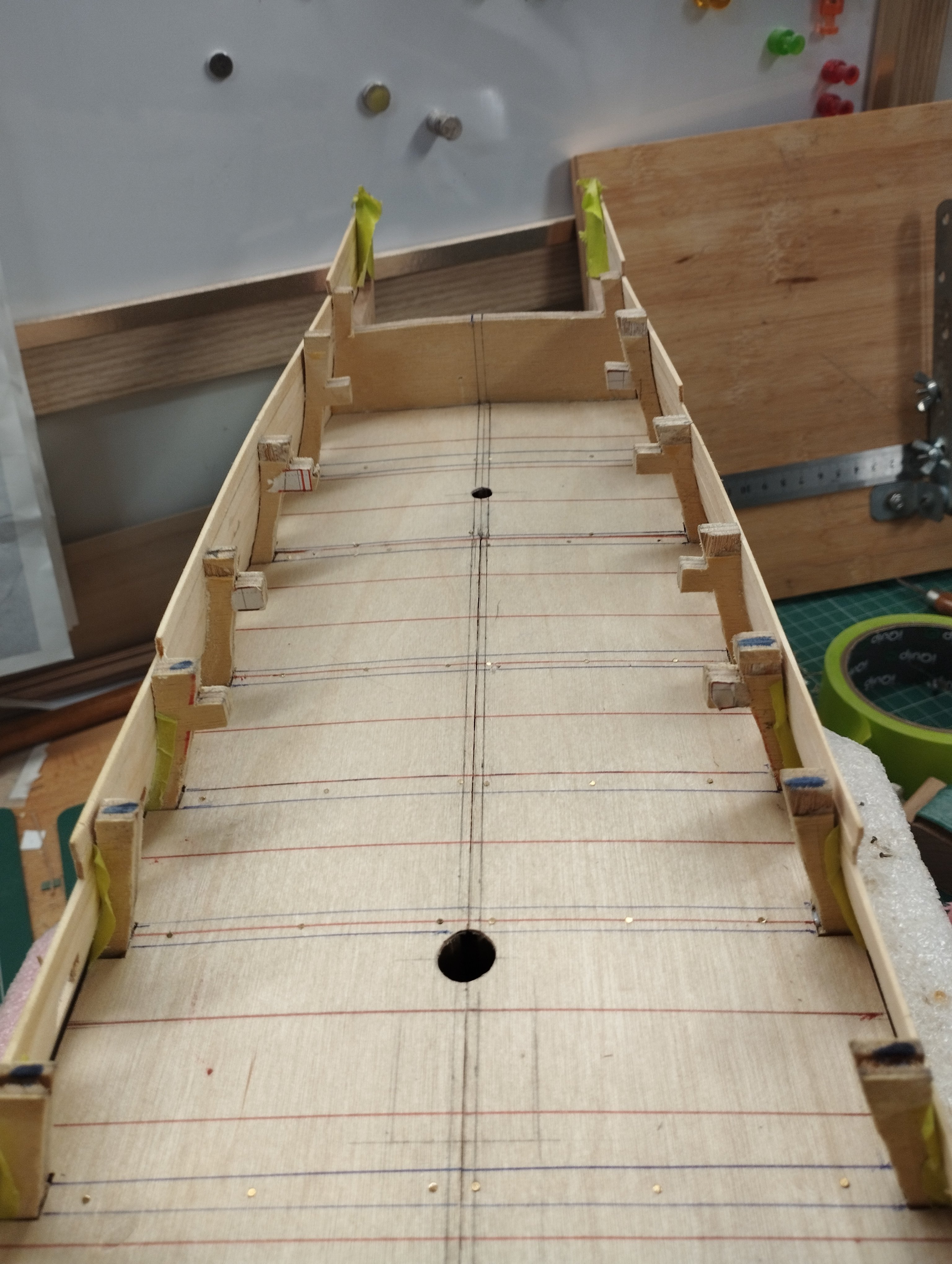
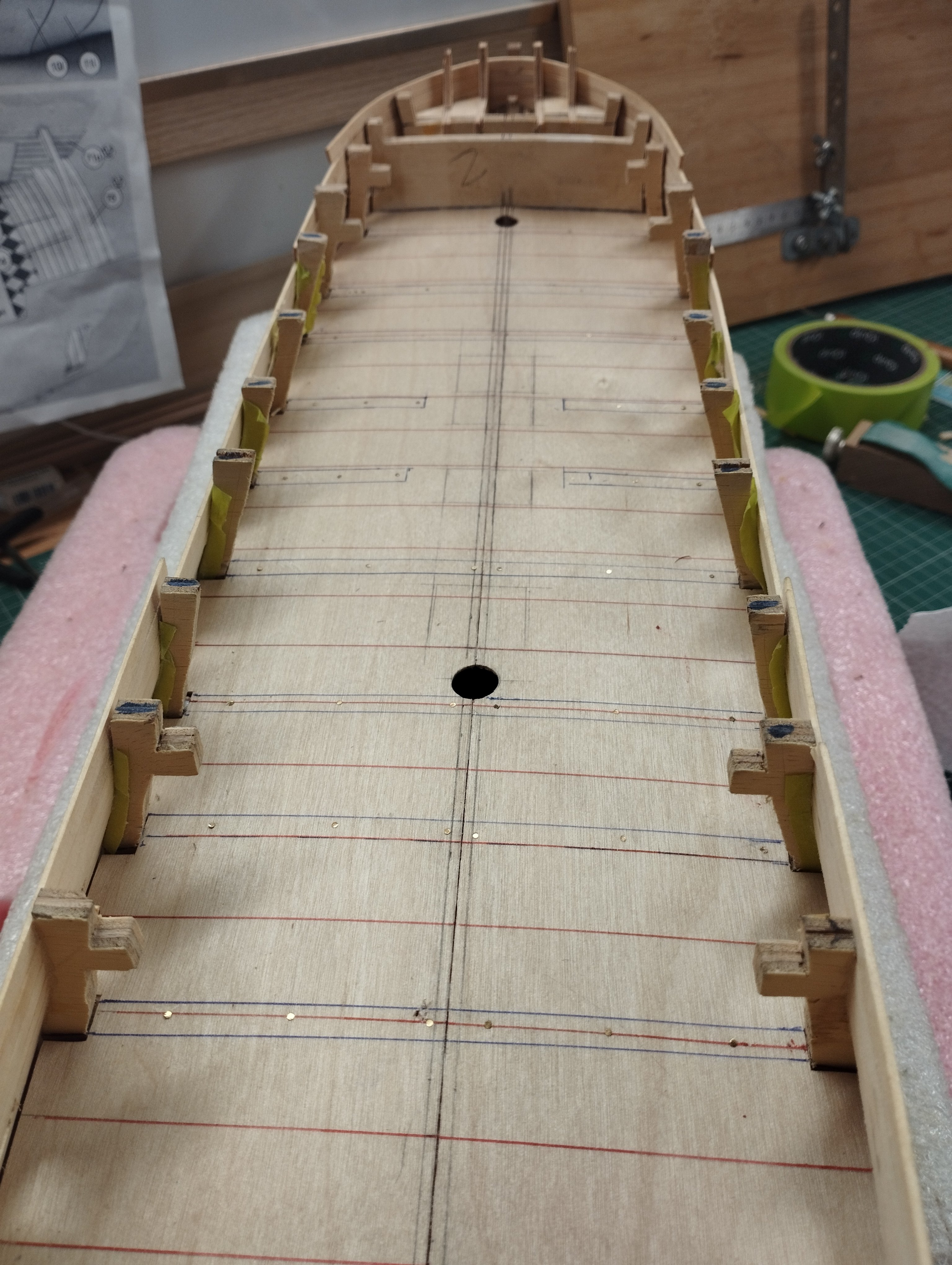
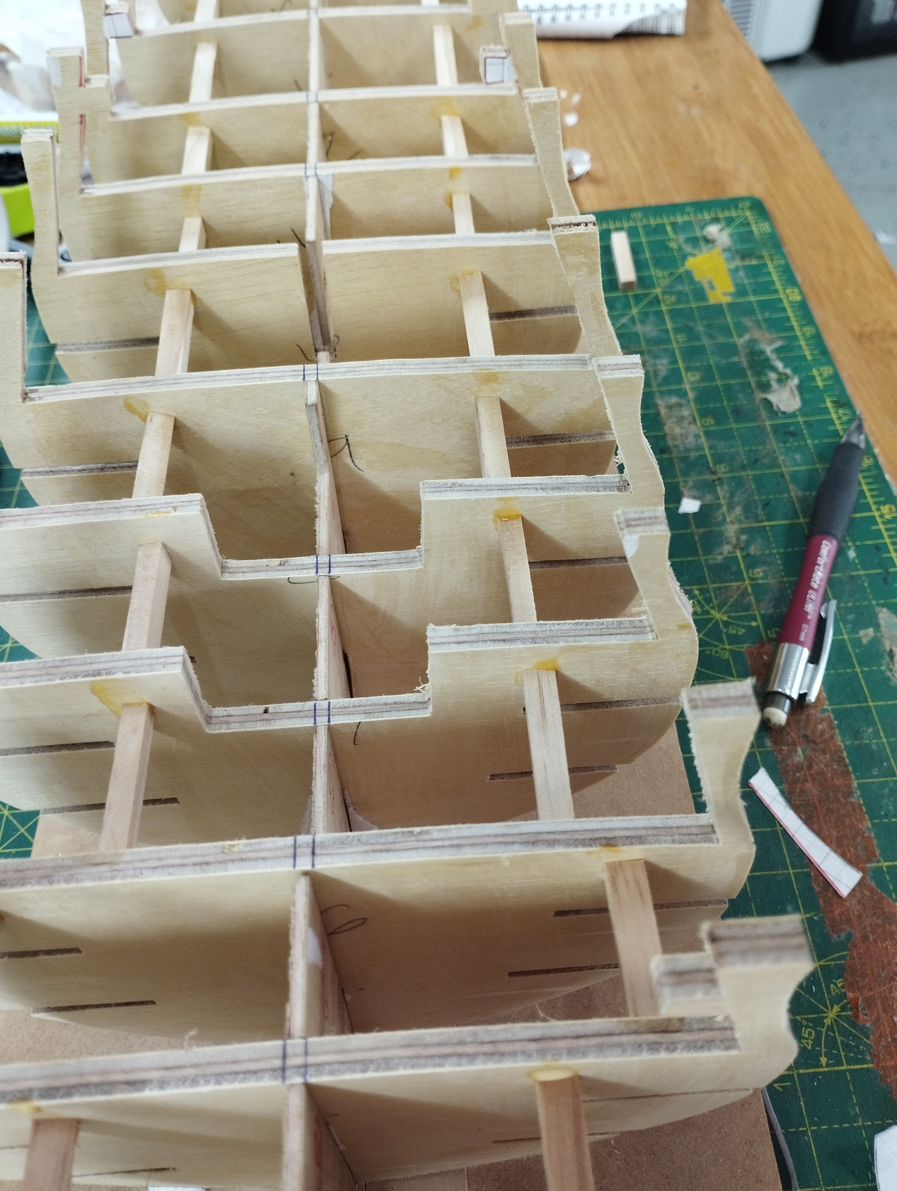
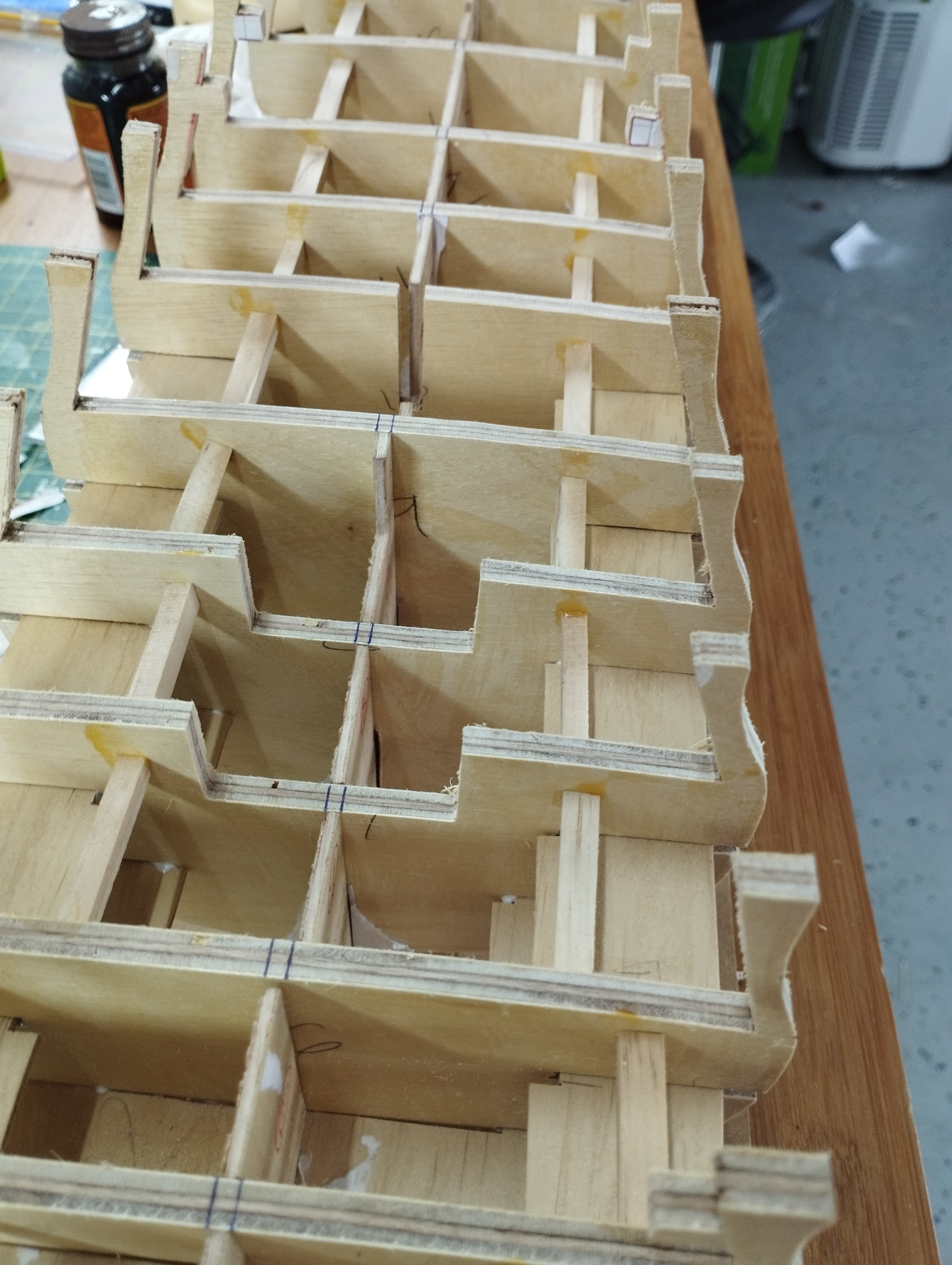
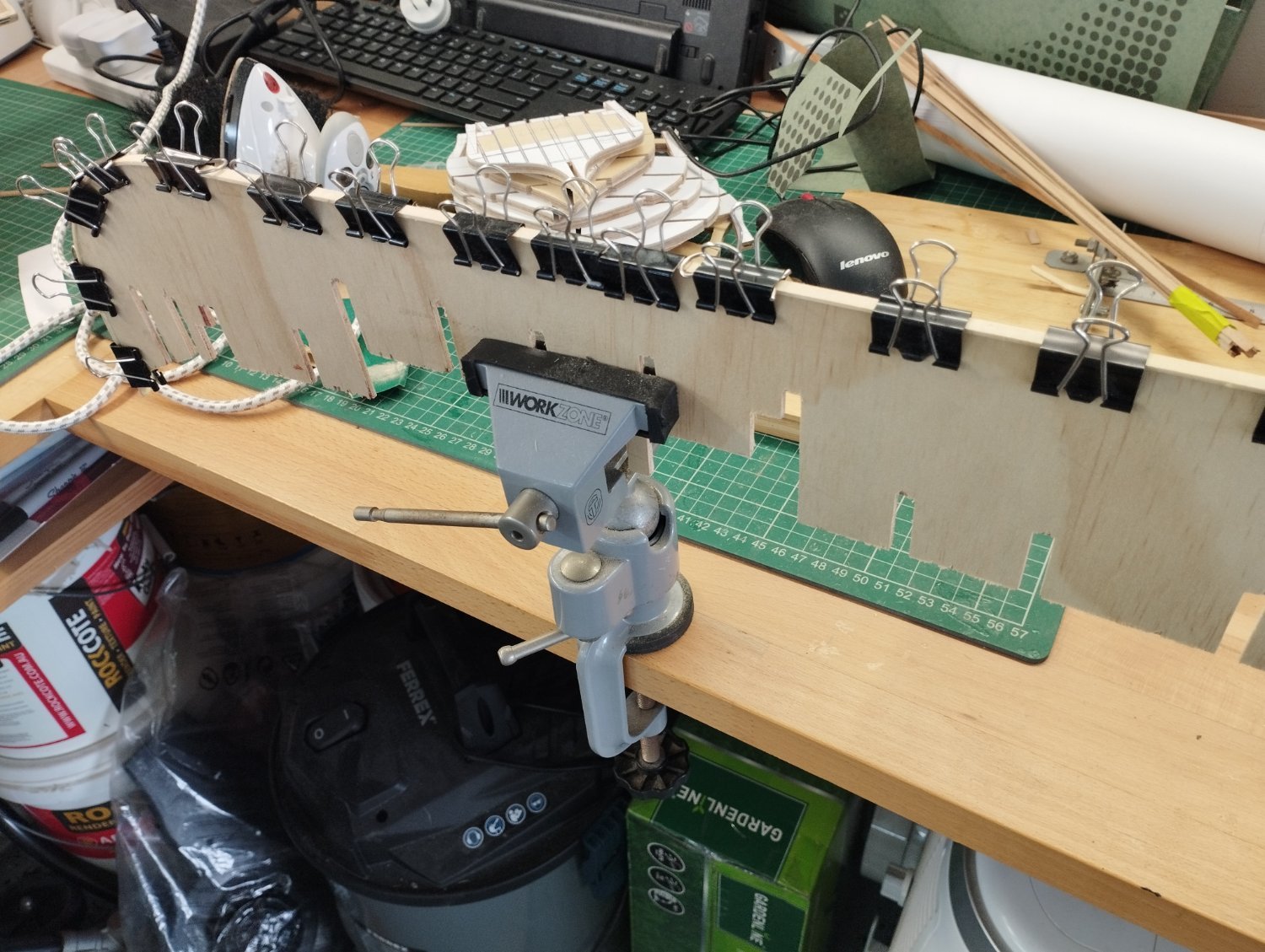
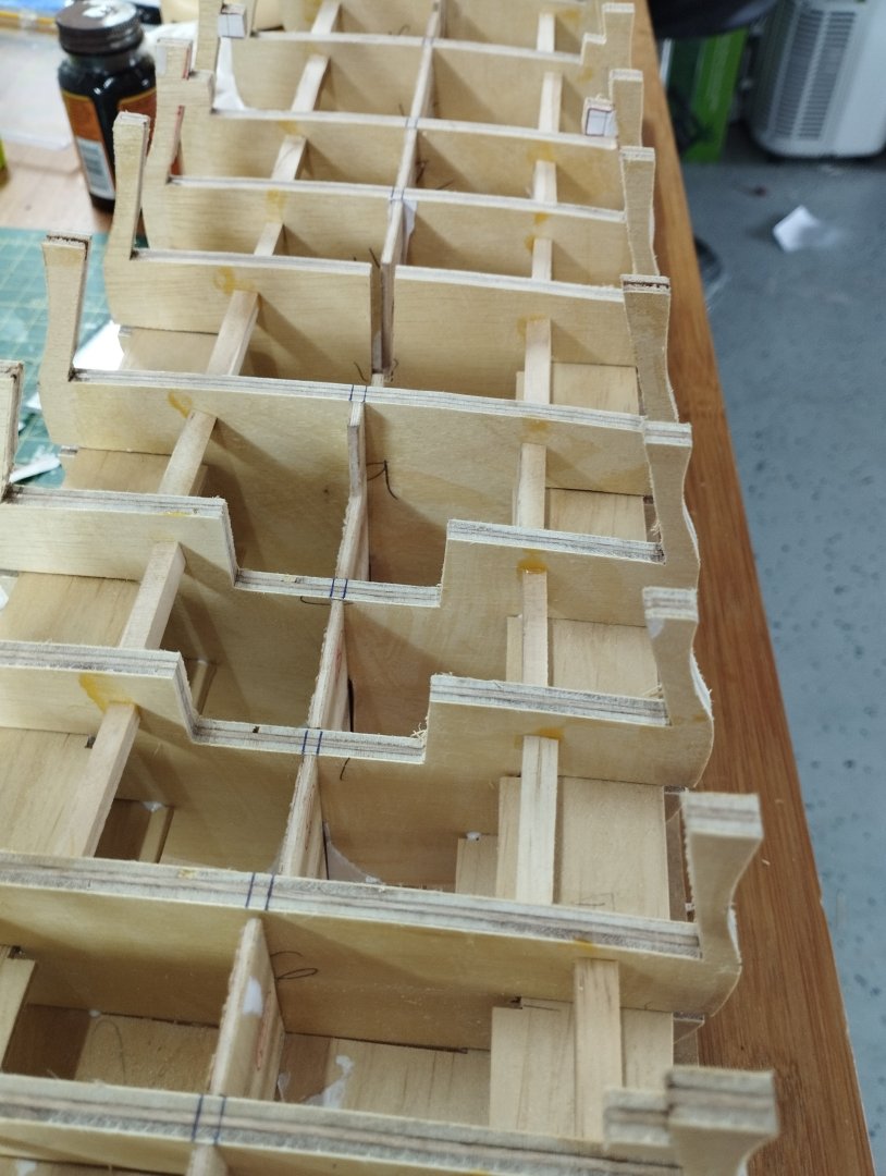
Hi All Thanks for the likes. Onto fitting the bulkheads A quick jig was made to keep the spine vertical whilst the bulkheads were fitted. Bulkheads kept square using Lego and clamps Once all bulkheads were fitted I added spacers to keep everything square, this is simply achieved by taking measurements of the gaps between the same bulkheads on either side of the spine and taking the average, two pieces of stock are then cut to that length and glued in place between the bulkheads The 3mm ply spine is still flimsy at this point so bracing pieces are required. These are cut from the templates provided and 3mm ply is used. I cut the bracing pieces roughly 5mm less wide than the templates so that the edge of the bracing pieces were clear of the bulkhead edges.. Following shows a couple of the bracing pieces cut and installed clear of the bulkhead edges Gaps in the bulkheads are plugged with some pine and sanded flush The frame is now rock solid and straight Thanks for dropping by Mark


-
Hi All Thanks for the likes @GrandpaPhil hope you start back on your card version, it's looking good so far @jpalmer1970 thanks, happy to have you along Ok, stem part next....this has been broken down into its component parts and glued up I've milled some cherry to a 6mm thickness for the stem, keel/false keel and stern post pieces and mixed some black acrylic paint into PVA glue for the joints. Some of the joints are not perfectly tight but I'm fairly happy for a first attempt All glued to the "keel" piece I've scored a line along the cherry 1mm in from the "keel" piece (if you zoom in really close you can just see it) , I'll cut this away after the first planking to use as a rabbet for the 2nd planking. I'm hoping the scoring will help in a smooth removal The 6mm cherry is centered on the 3mm "keel" leaving 1.5mm on each side to take the 1st planking which will be.......yeah, you guessed it 1.5mm in thickness. Thanks for looking in Mark Mark

-
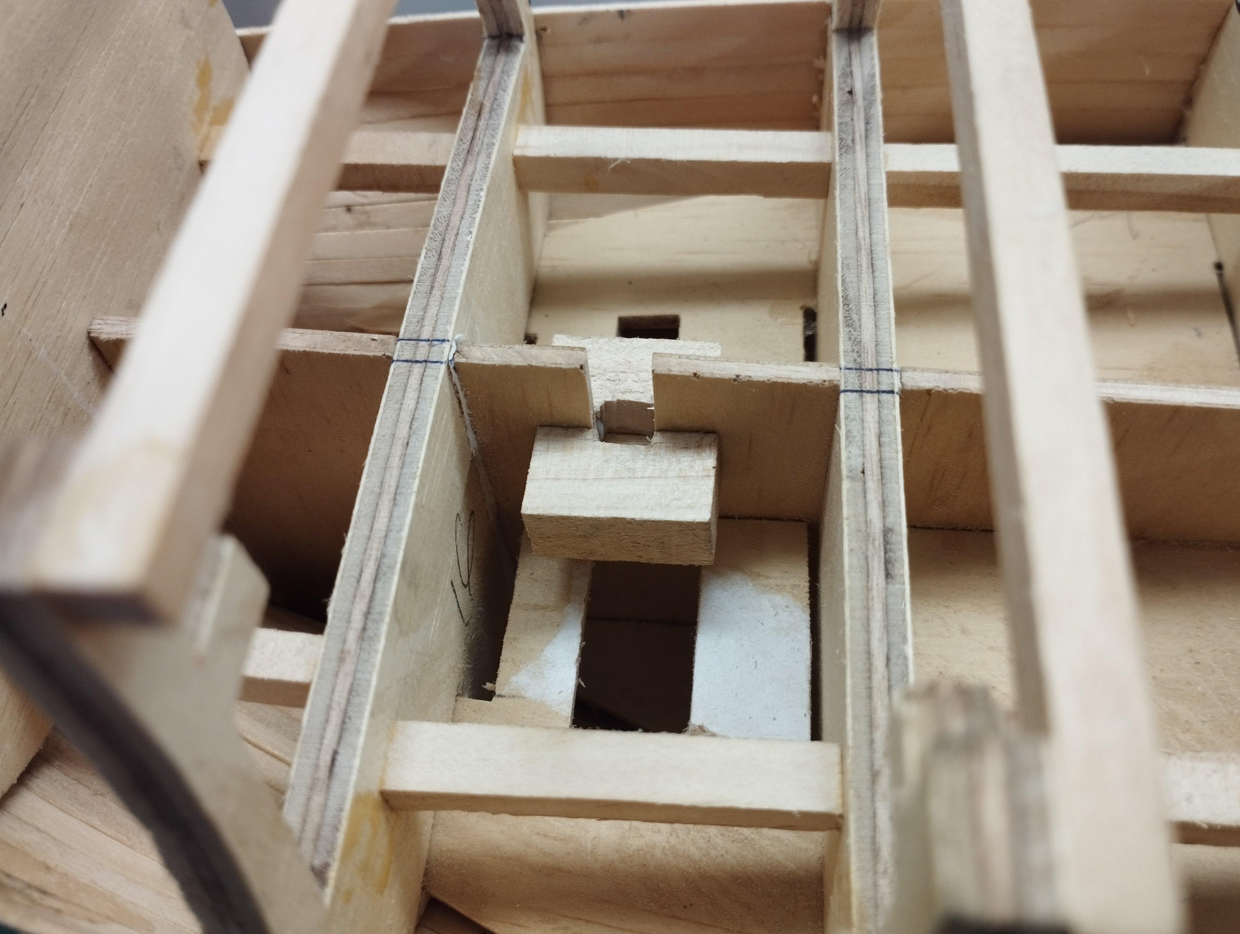
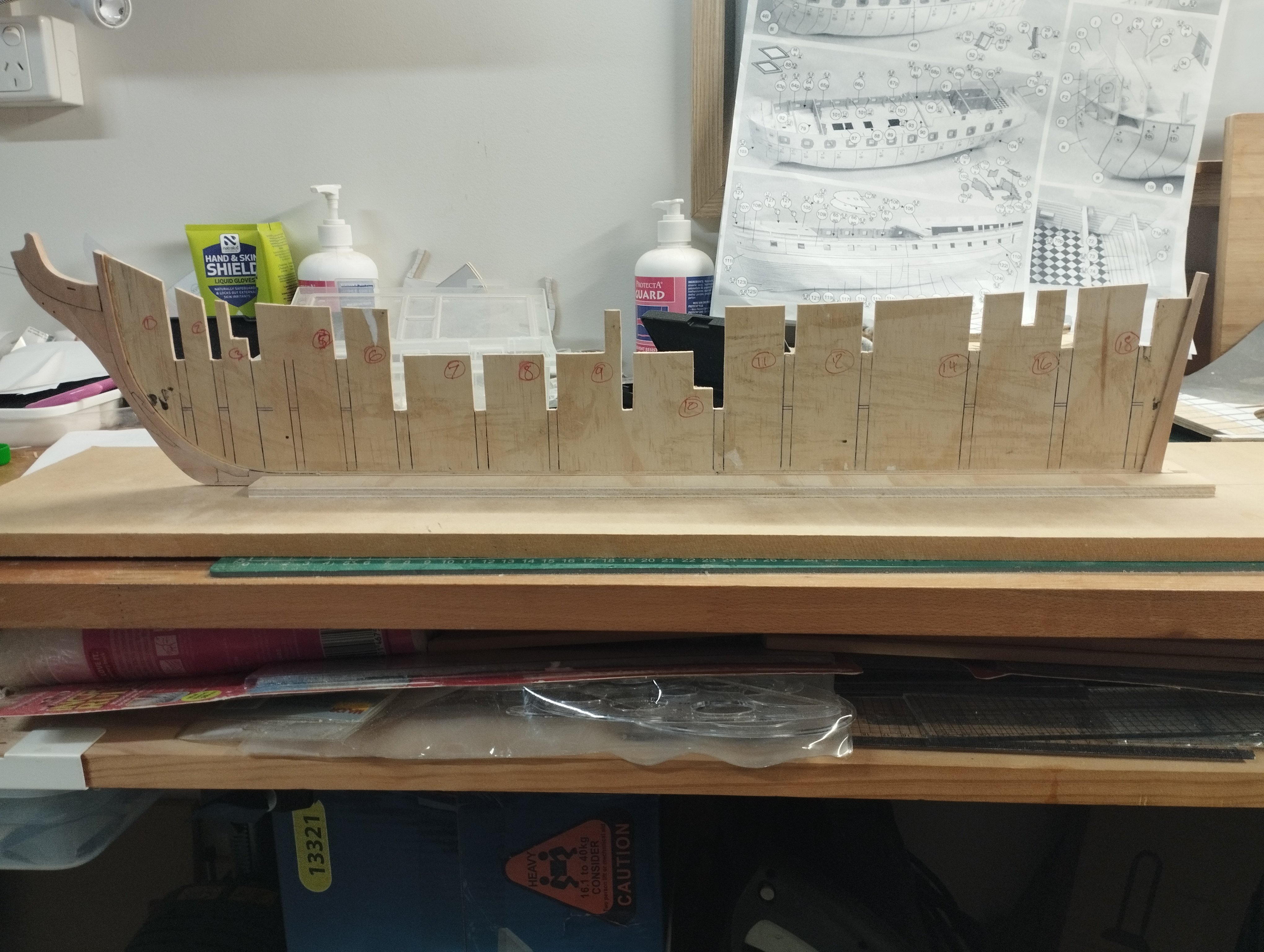
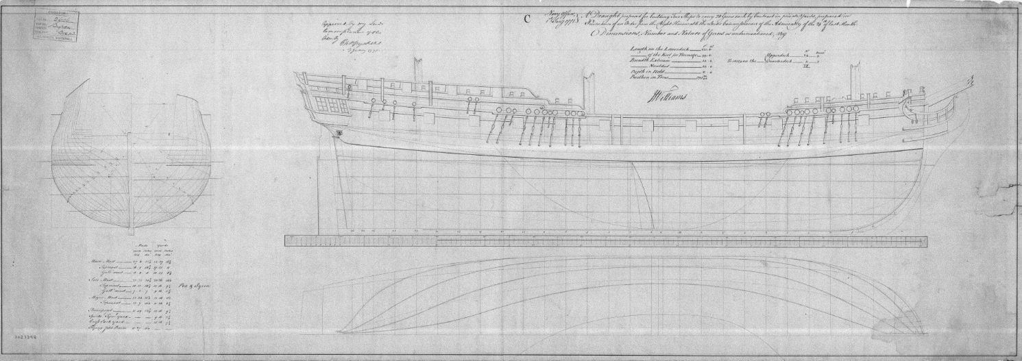
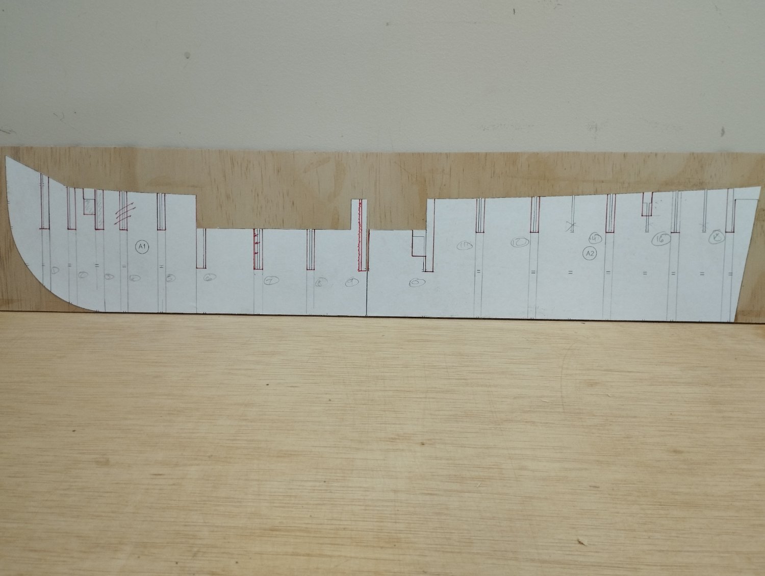
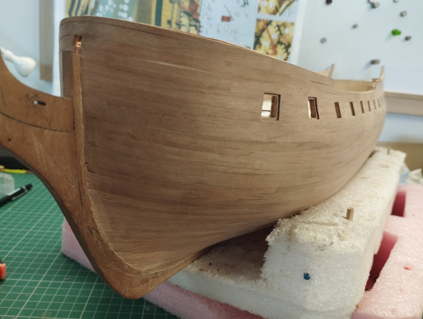
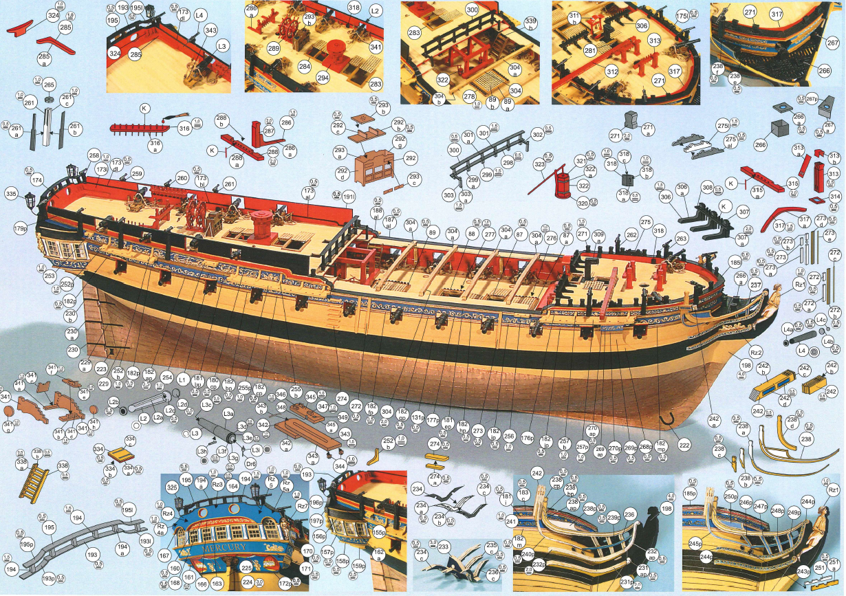
Hi All It's with a little trepidation that I start this build log and as such a word of caution is required..... If you are of a nervous disposition and easily offended by poor quality workmanship, find a complete disregard of historical accuracy extremely upsetting and deem lowering the quality of this forum as morally outrageous then then I beg you to avert your eyes and leave now as the following content is probably not for you. Ok, for those of you that are still with me and made of stronger stuff there are some points that I need to make you aware of before I start a) I am not at one with wood b) tools are not a natural extension of my hands c) I do not see a plan on paper and turn it into a 3D matrix in my mind and compute complex curves and angles instantly d) If there are two ways to do something, I'll choose the wrong one e) If there is an easy way and a hard way, I'll inadvertently do it the hard way e) I was not blessed with any real woodworking skills and I have to make do with my God given abilities f) I enjoy making ship models and I struggle daily to overcome the points above. Let's begin This is my fourth model ship (see signature for details) and my first attempt at a scratch build. I'll be using the paper model by Shipways as the basis of the build and will be using as much as what is contained in the paper parts as templates to assist as I attempt to covert it into a wooden model. I've also downloaded the plans of Syren from wiki commons as an aid as the paper "plans" do not contain plans as such...what is provided is along the lines of Syren download The content of the paper model is really good and has excellent rigging, belaying, mast and yard info and in my opinion is as good as Caldercraft rigging plans...small example of rigging info Masts The paper model is at a scale of 1:96 so the first order of the day was to scan the sheets and print out at a scale of 1:64 and to try and identify what parts are printed on the 30+ A3 sheets and compile into a spreadsheet for ease of location. Bulk heads were cut out of 6mm plywood....this is just normal ply from the local hardware store (Bunnings), I know there is discussion in another topic on the merits of using something better but I've got to work with what I can get easily in my little corner of Queensland.... but first a little manipulation of the templates was required. As below the bulkhead templates only go to the main deck level and make no provision for the bulwarks The way the paper model caters for these is to add internal supports to the deck as shown in the photo below which has been copied from the paper build log of Mercury by @catopower These supports are few and far between and made from the templates I've used these templates to form an extension of the bulkheads I know I could have used the Syren plans to form the bulkheads but I want to use as much as what is provided as part of this build "Keel" piece is made from 3mm plywood....I can hear the gasps now "that won't be strong enough to support 6mm bulkheads....far too flimsy"....I originally considered the 6mm ply but this would result in a loss of definition of the bulkheads once a 6mm slot was cut into them. I've repositioned the bulkheads slightly to centre them over where the thin card bulkheads would have gone. The bulkheads at stem and stern have been positioned so that the face is identical to where the card bulkhead would be as I need to use these as refernece points for the bow and stern works. I've also omitted 3 bulkheads (no's 4, 13 and 17) as I deemed them not necessary with the 6mm ply and closeness to the others A strip of 1.5mm has been glued to the "keel" piece to form a rabbet for the planking. I'm further on than this but will call it a day for this initial post. Thanks for looking in Mark Thanks for looking in


-
Using a card-kit to ¨scratchbuild¨ a ship?
Mr Pleasant replied to ubjs's topic in RC Kits & Scratch building
I'm doing this for the HMS Enterprise using the Shipyard card model kit. Have upscaled from 1:96 to 1:64 and I'm just building a rough prototype to work out the stern and bow areas.....watch this space, build log coming in the New Year once I've worked through some of the issues in relation to converting this to a wood model as to what is provided in the paper plans -
Thanks Patrick I'll certainly be following your build of the Mary Rose
- 50 replies
-
- 1
-

-
- mary rose
- caldercraft
- (and 1 more)
-
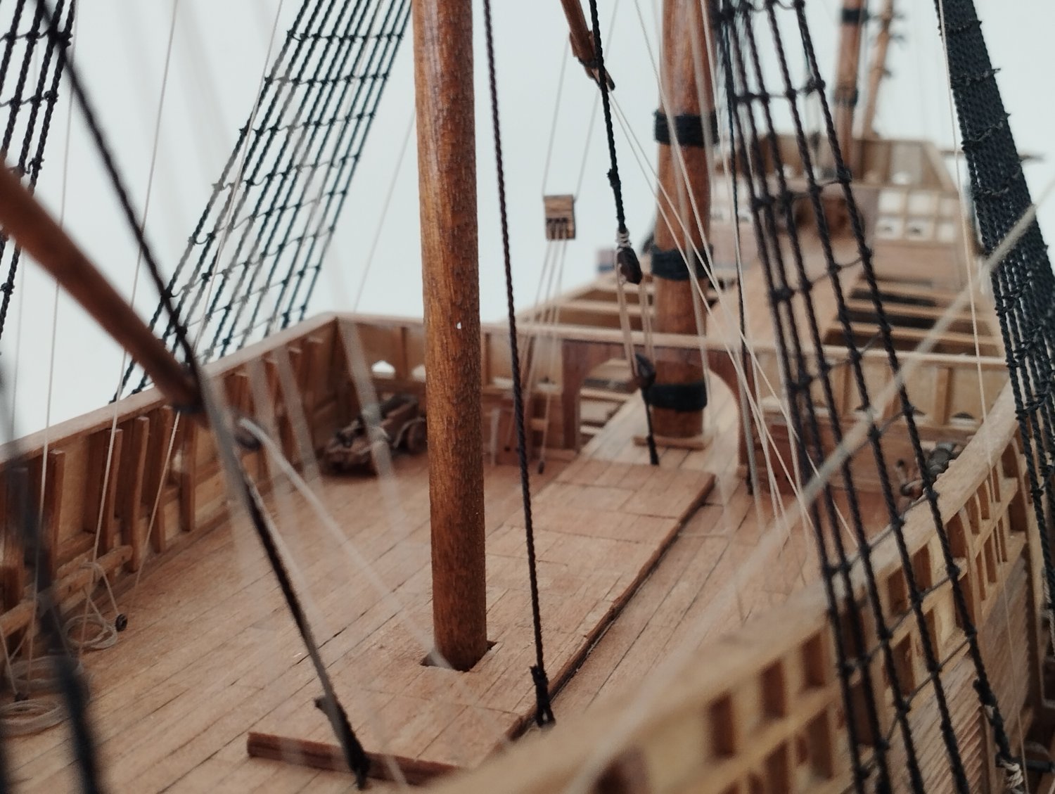
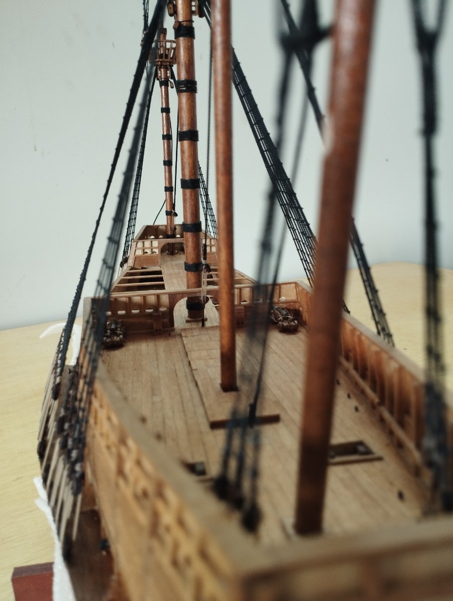
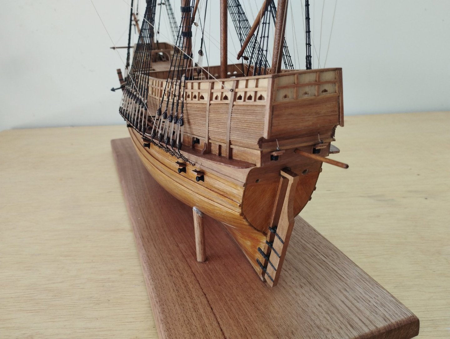
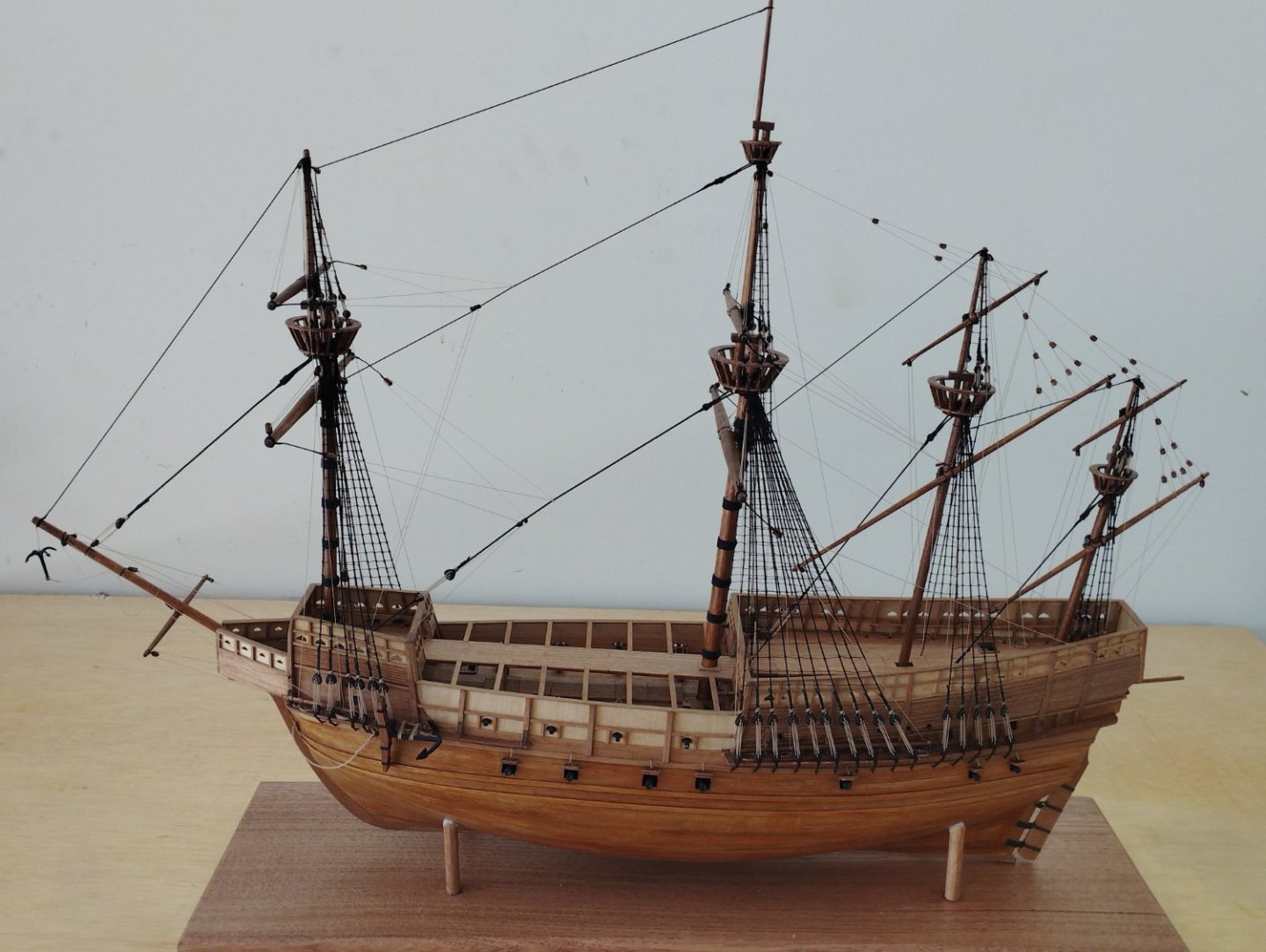
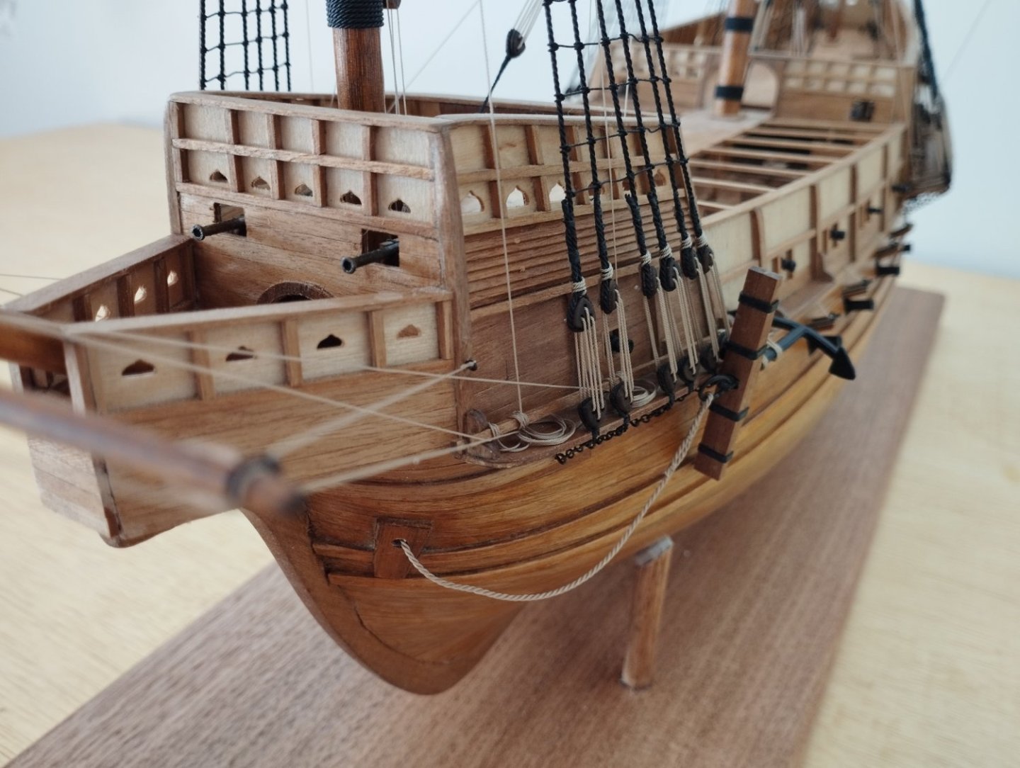
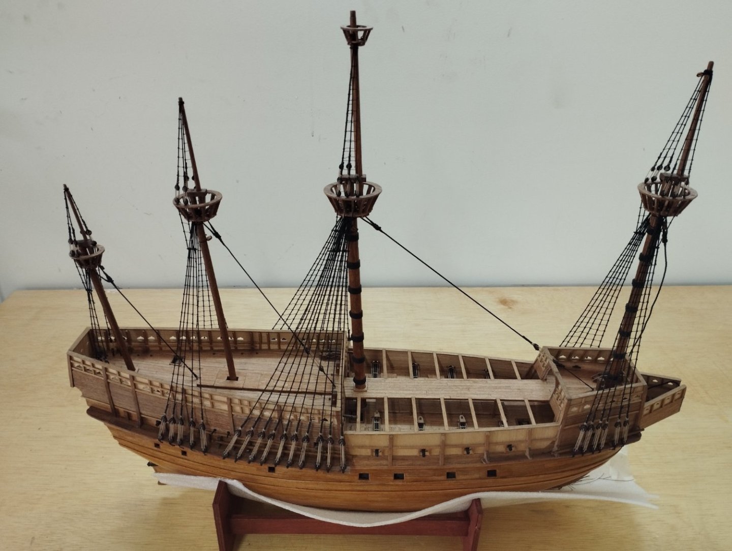
Hi All Thanks for the likes and comments and thanks to Fishhooks for posting on the error in the mast dimensions provided in the plans. This is what the forum is about after all, I've learned a lot and continue to do so and hopefully this build log will prove some assistance to those who are in the middle of building this model or who are considering starting. I started this on the 28/12/2020 and finally finished on 05/09/2023. The model out of the box builds fairly well and I think the preceding posts point out all the main pitfalls I came across. The only things I've changed are the making of my own rope and the addition of the two cannons at the stern. The following photos show the end result of a model I've enjoyed building. Thanks again for stopping by Mark


- 50 replies
-
- 15
-

-

-
- mary rose
- caldercraft
- (and 1 more)
-
Will be interesting to see if this solves the problem entirely or if you still need to widen the channels. If you're not doing a build log a pm would be nice when you get to that stage to satisfy my curiosity. Mark
-
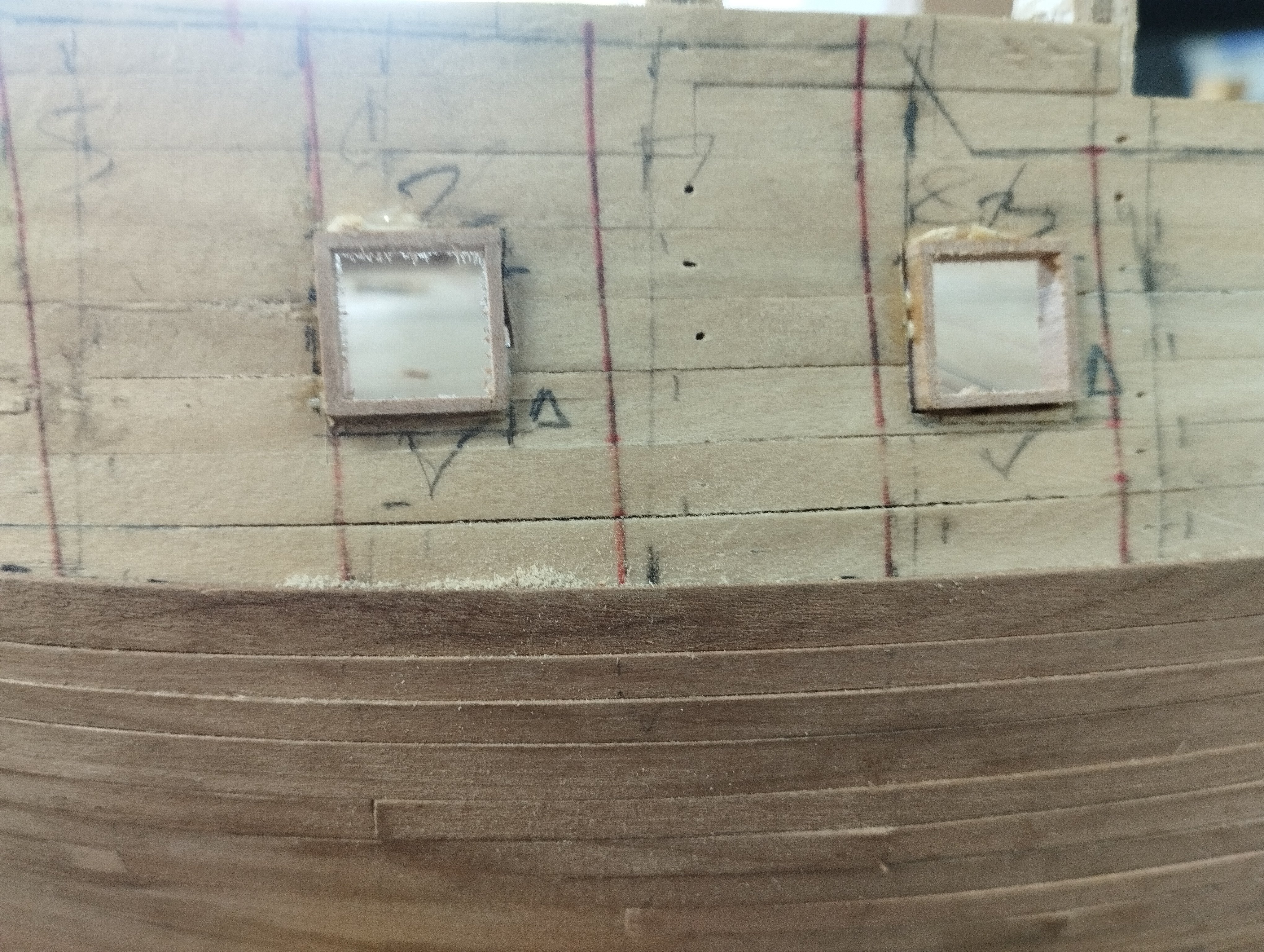
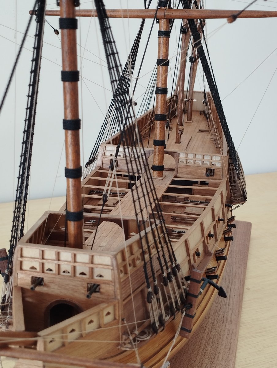
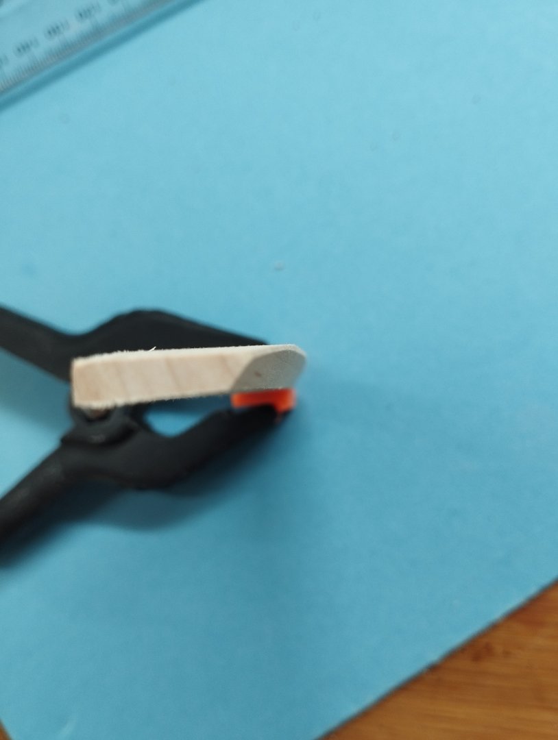
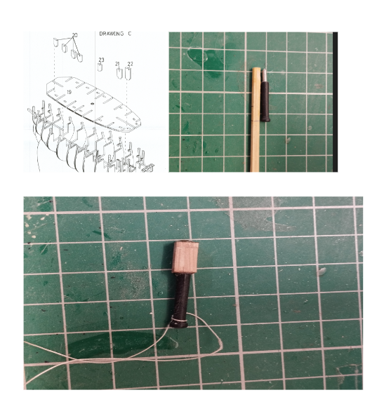
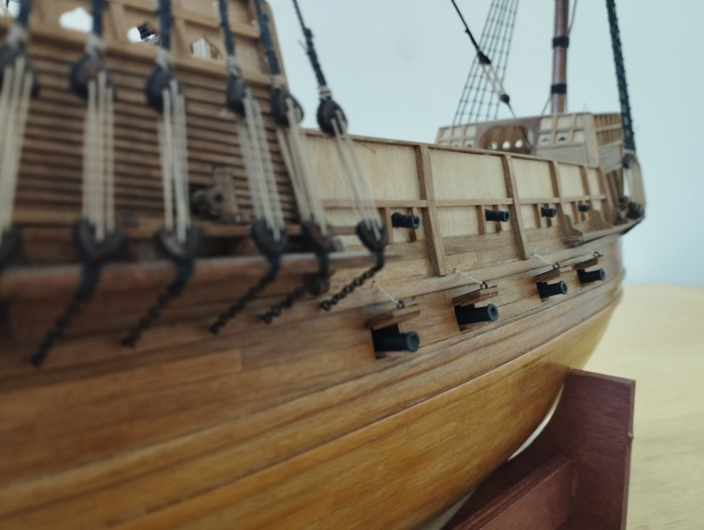
Hi All Thanks for the comments and likes. Small update on progress... Cannons are now installed but not without a few small issues shown below. The plans asked for dummy cannon blocks to be installed at the framing stage in the pre defined slots shown in the top left image with the intent that holes are drilled into the blocks to accept the dummy cannons. Top right image, the wood gauge shows the depth from the dummy block to the edge of the frame (pencil mark). The unpainted part of the cannon is of a lesser diameter than the barrel and is to fit in the hole drilled in the block. However following this course of action would lead to the cannons being far recessed inside the hull. To overcome this blocks were made and the cannons fixed to these to effectively increase the length of the cannon as shown in the bottom image. The assembly was then glued against the dummy cannon blocks....the thread was was used as a recovery mechanism in case the cannons fell inside the hull whilst the glue was setting Cannons are now installed and I'm onto the running rigging Thanks for dropping by Mark
- 50 replies
-
- 8
-
-
-
- mary rose
- caldercraft
- (and 1 more)
-
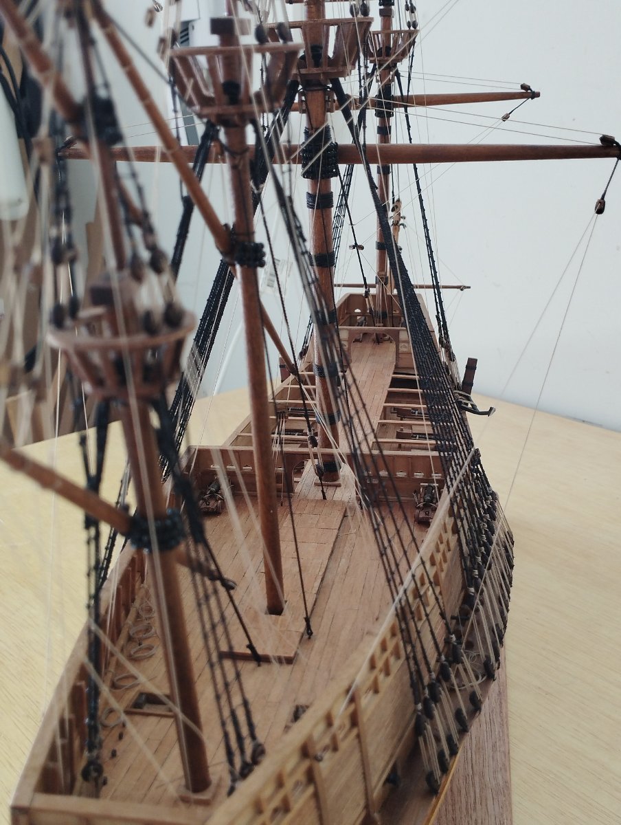
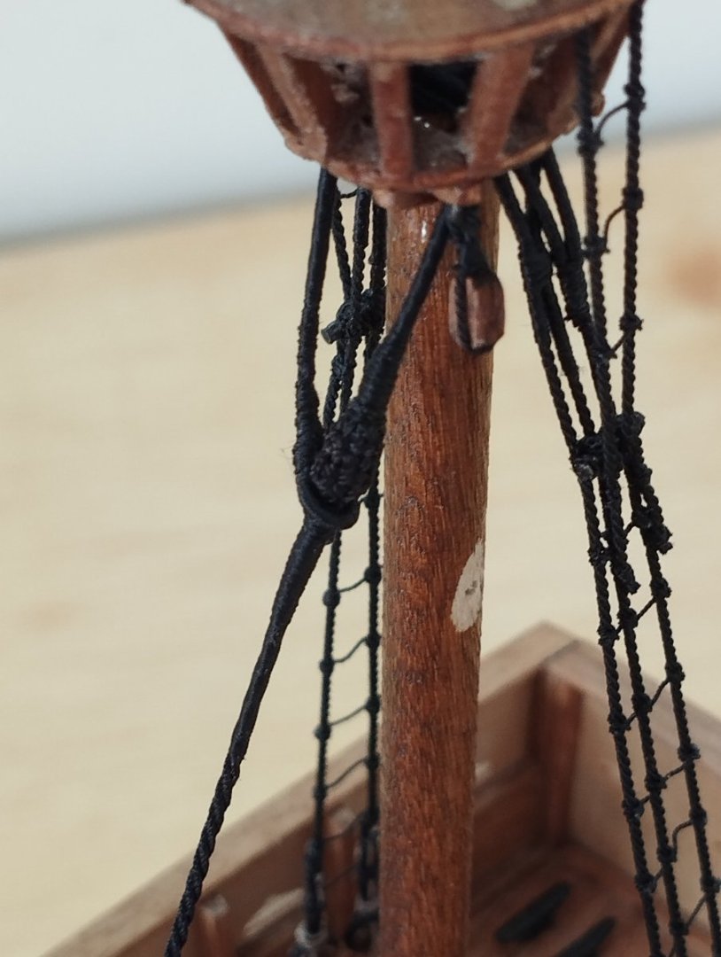
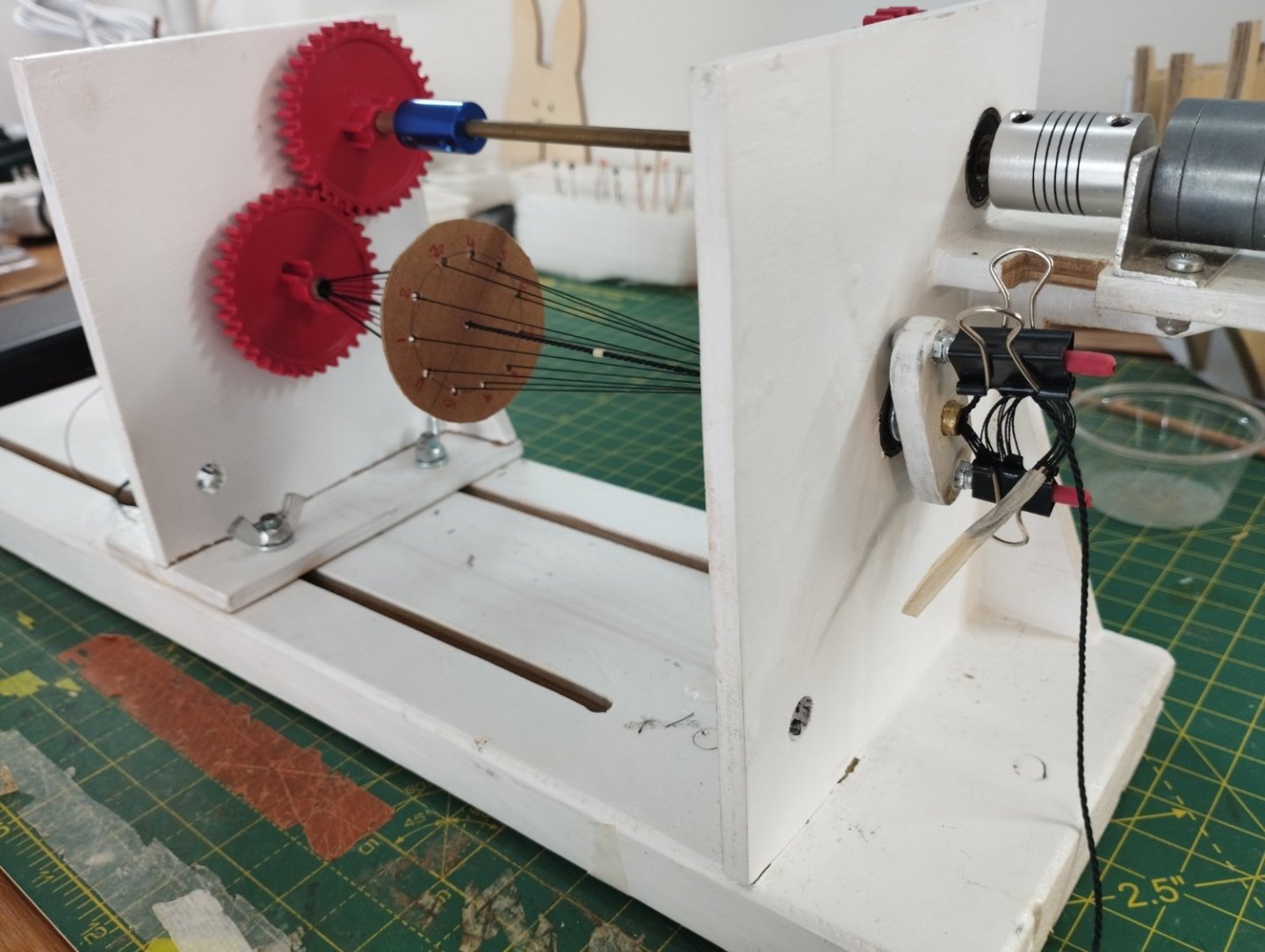
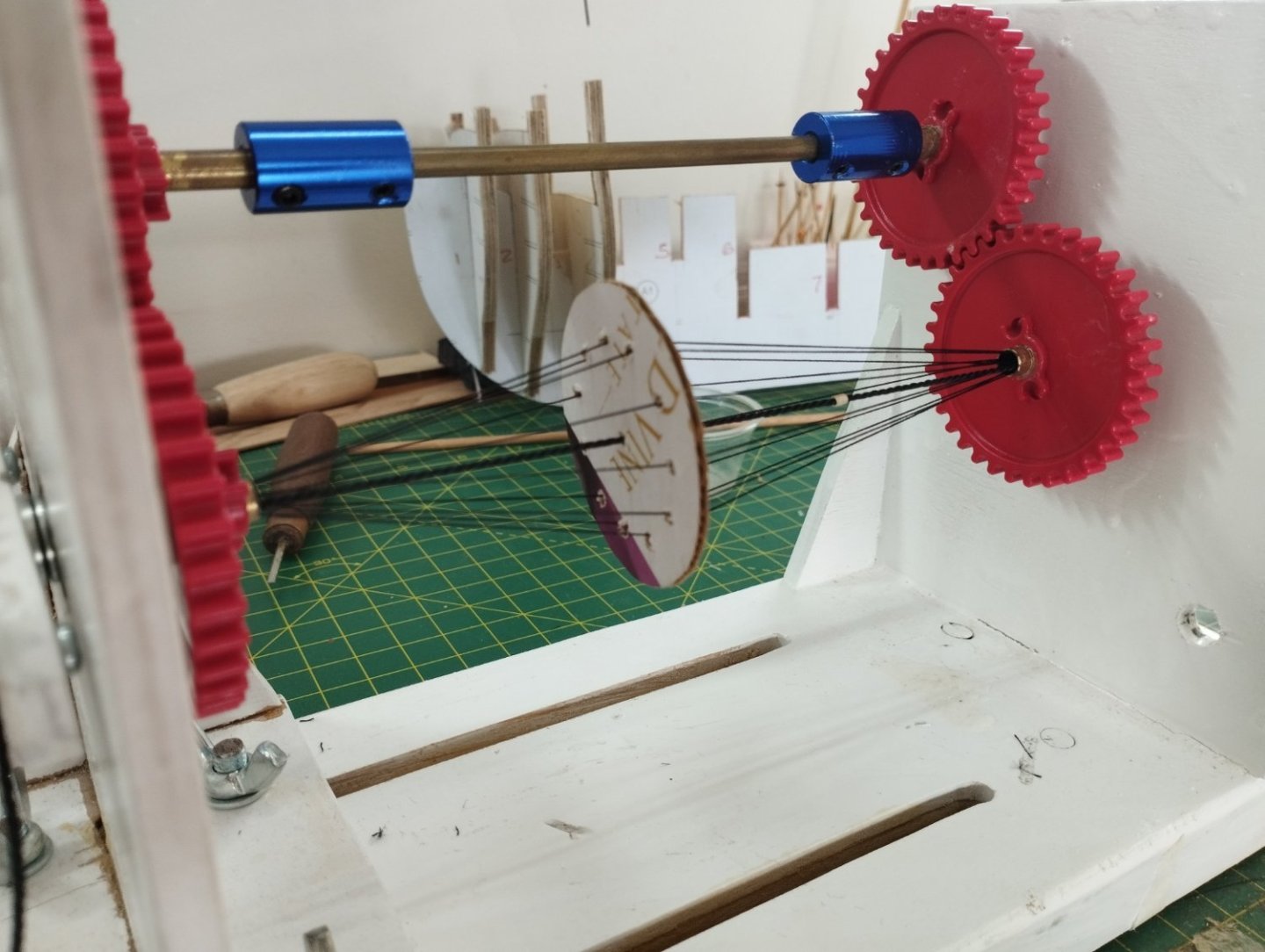
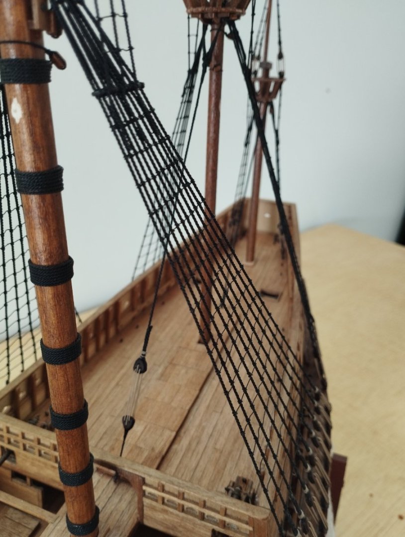
Wow, where did that time go!!!!! 9 month since my last post. Standing rigging and ratlines are now pretty much complete, I've done the stays with "mice" although the instructions didn't call for them and the plans were a little unclear in this regard and the AoTS that I have doesn't have a lot of detail regarding the rigging. There's quite a lot of resource on this site on the making of a mouse and after quite a lot of trial and error I've managed to get something that I'm fairly happy with The setup that I got best results with was to use a serving machine. This allowed me to keep the weaving threads tight but also made the weaving a lot easier than other methods I tried as I could keep turning the weaving threads towards me once I had gone over and under a pair. Thread used was Mara 30 and is probably a little on the large size but was all I had in large quantity as there is a lot of waste, 11 weaving threads were used. The circle used to keep the threads separated is simply a piece of card with the 11 holes punched thorough, I numbered the holes as I found this helped me keep track of the weaving thread as I went under and over the threads. The mouse former was turned on a lathe and is roughly 3mm in length Once this was set up it was "simply" a matter of threading the weaving thread under and over a pair and turning the gears of the serving machine towards me to weave under and over the next pair and so on. Once the former was covered then I served a length of the stay and formed the eye to stop against the mouse. Following photos give an idea where I'm at Thanks for looking in and hopefully my next post won't be too far away Mark


- 50 replies
-
- 8
-
-
- mary rose
- caldercraft
- (and 1 more)
-
Hi Meredith Have sent you a PM Mark
-
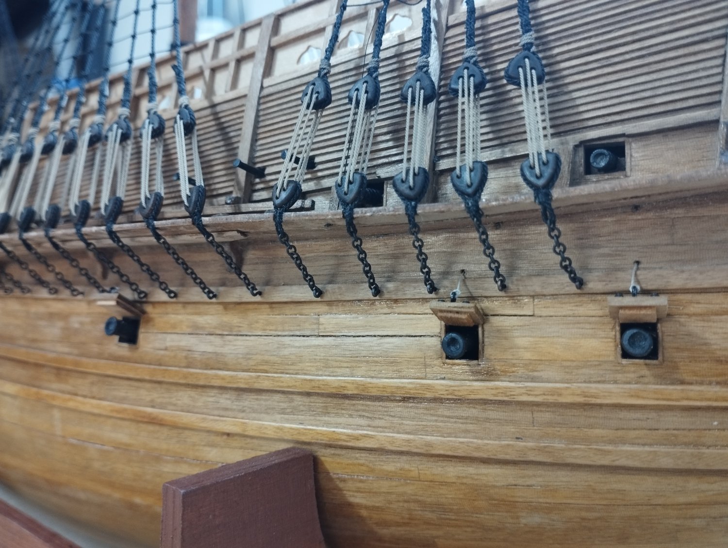
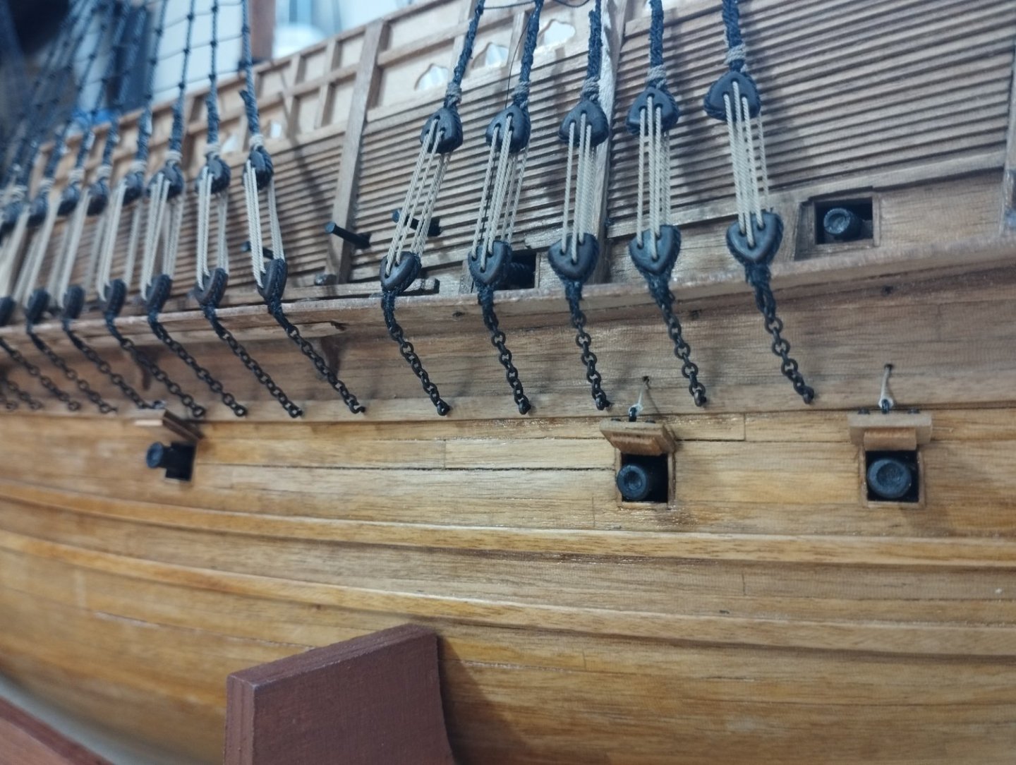
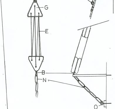
Thanks Steven I have the AoTS book and did consider the chainwork option but the chain supplied in the kit is so soft that I think I would have struggled soldering the ring from the dead eye to it and I didn't fancy making up my own chain so I elected to go with the plans as below where "B" is thread Also, it's not the first time I've had issues with Caldercraft models and the shrouds. I got caught out on the Endeavour and this was a problem with the kit and is discussed by others in a thread in the "masts and rigging section". I think it's something similar in that the main mast should be slightly longer than what is given in the plans and the channels should be slightly wider. But all good, hopefully others who are planning on building this ship can learn from my mistakes. Mark
- 50 replies
-
- 2
-
-
- mary rose
- caldercraft
- (and 1 more)