Supplies of the Ship Modeler's Handbook are running out. Get your copy NOW before they are gone! Click on photo to order.
×


hamilton
-
Posts
1,925 -
Joined
-
Last visited
Content Type
Profiles
Forums
Gallery
Events
Everything posted by hamilton
-
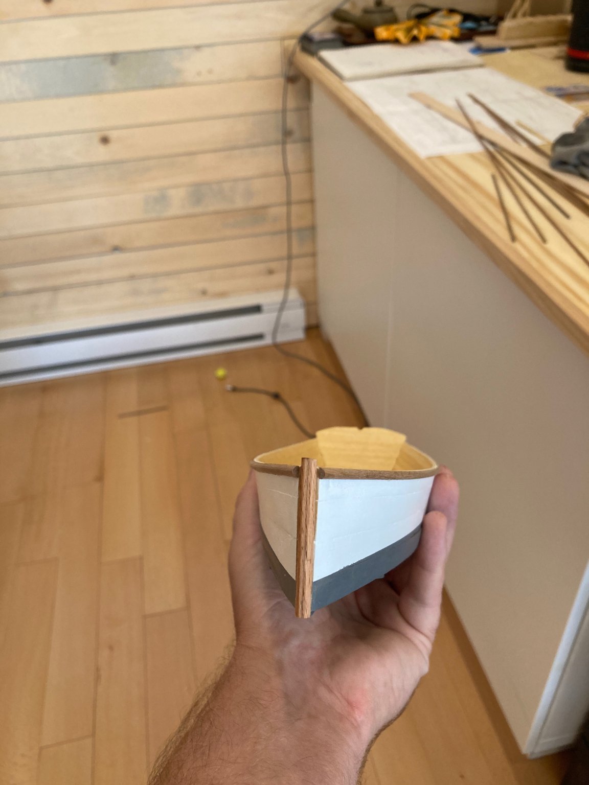
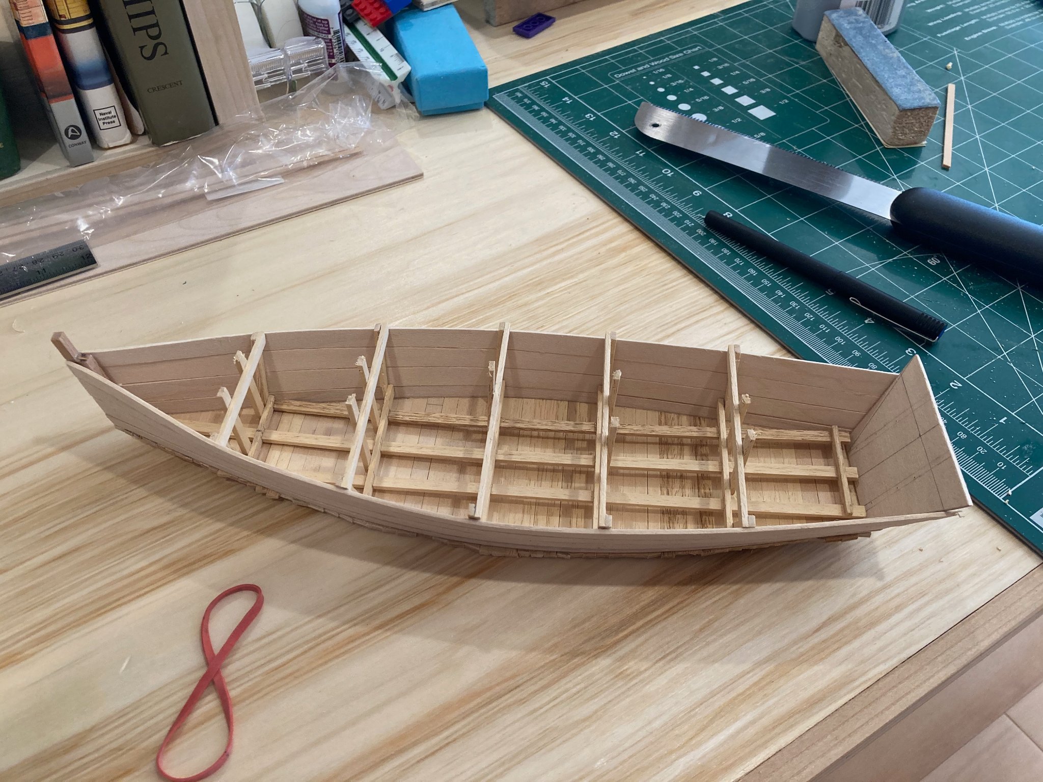
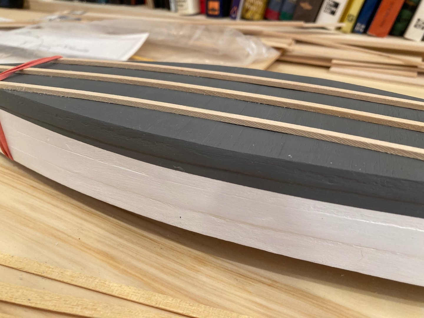
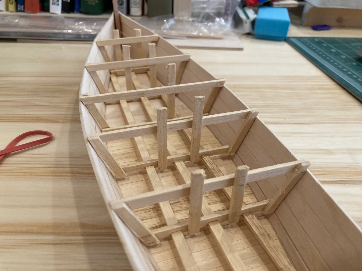
 Back in the shop again today - tail end of my summer vacation so trying to make the most of it! This morning, I installed the outboard rails - a sheer strake cut from 1/8 x 1/16 half-round mahogany and what I'm calling a "vanity strake" below that - 1/8" x .5mm pre-painted lime, which was included as outboard bulwark planking on the Corel Greuhound kit which I built up some years ago as HMS Blandford. I think the accent looks nice, though for a full sized skiff, this added feature would be pretty impractical - hence "vanity strake". After lunch I'm planning on starting to add frames inboard from 1/16 x 1/16 mahogany - so hopefully another update by the end of the day...really wanted to get this model finished before heading back to work, but it doesn't look like that's to be.....oh well - I'll be able to scratch out some time here and there before things get really busy at the office in September.... Bye for now and enjoy! hamilton
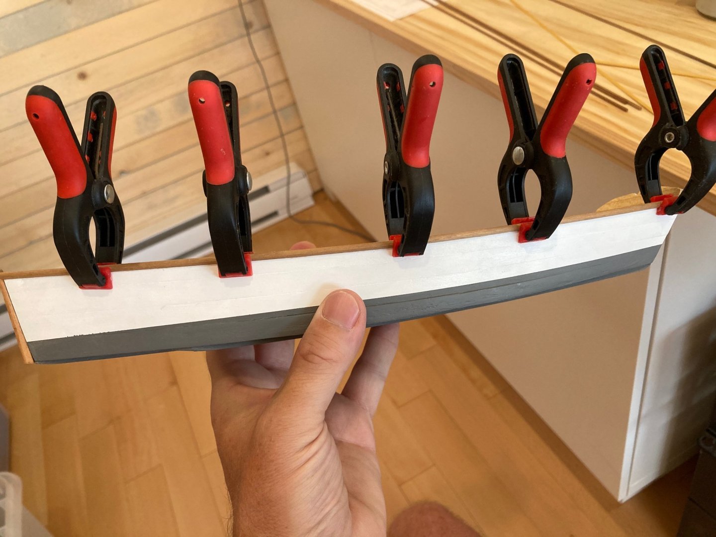


-
Thanks John - it certainly feels good to bring this little model together. Maybe back to something bigger once the summer's over.... hamilton
-
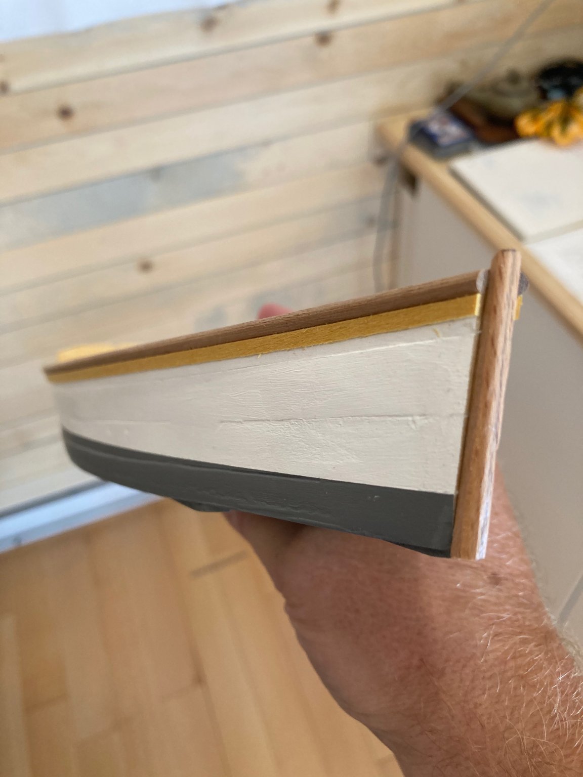
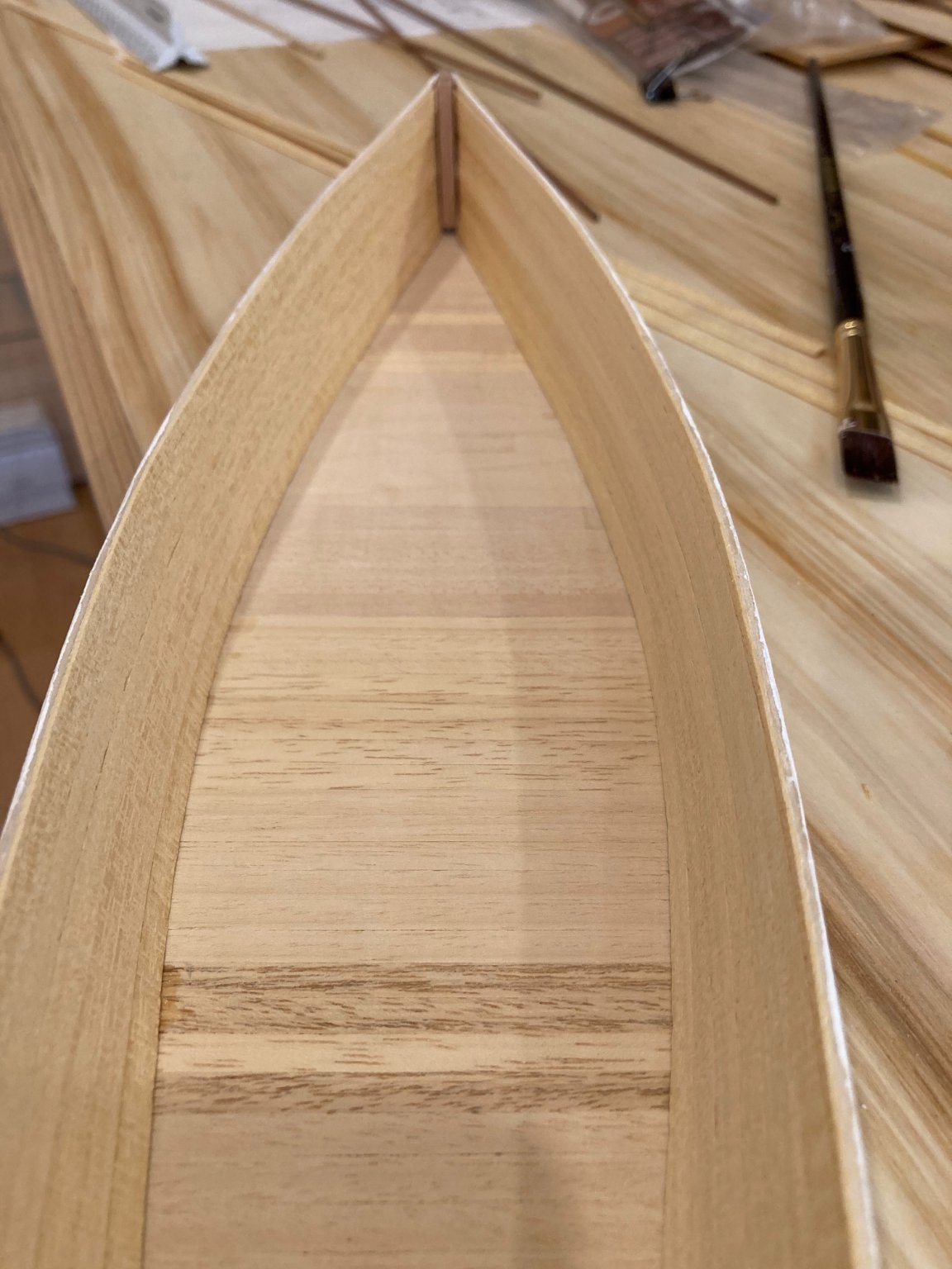
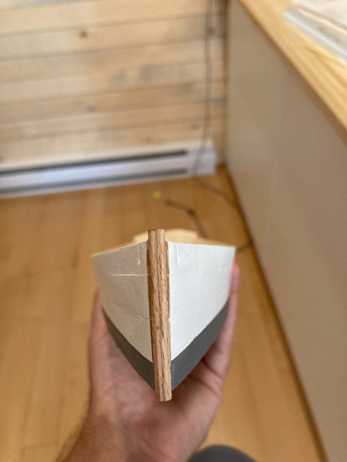
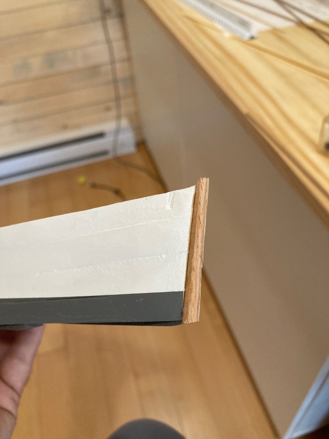
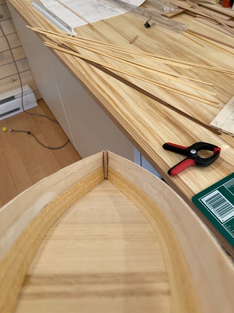
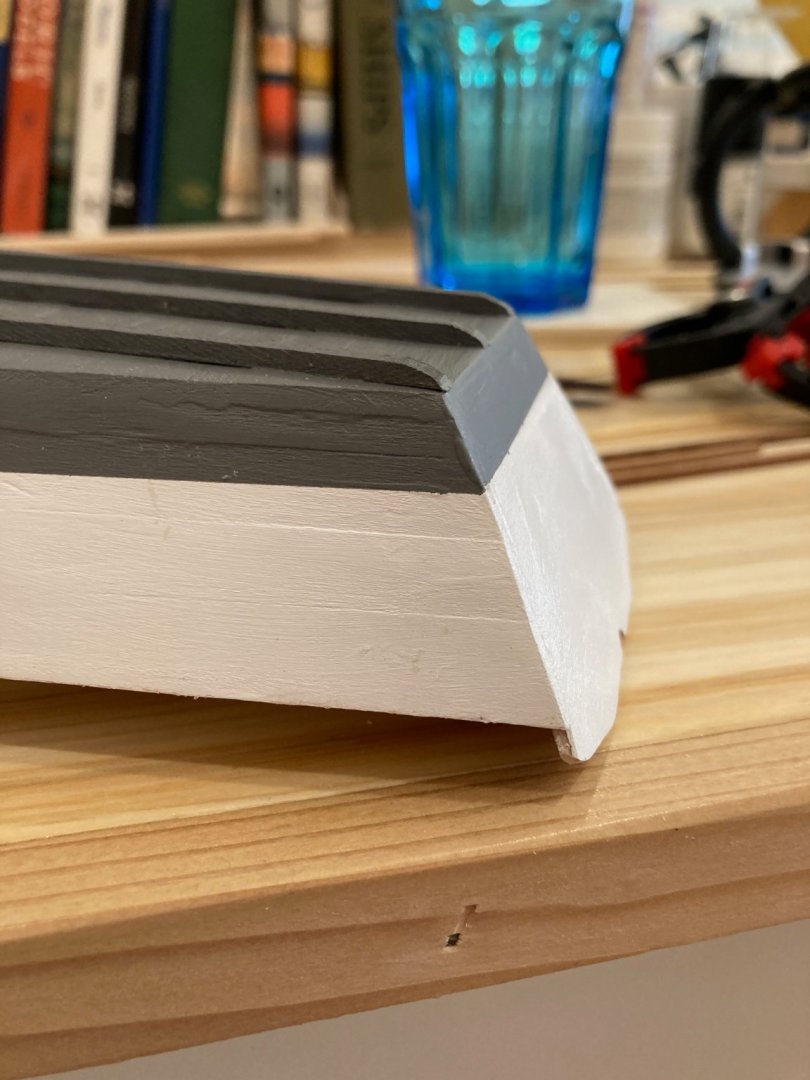
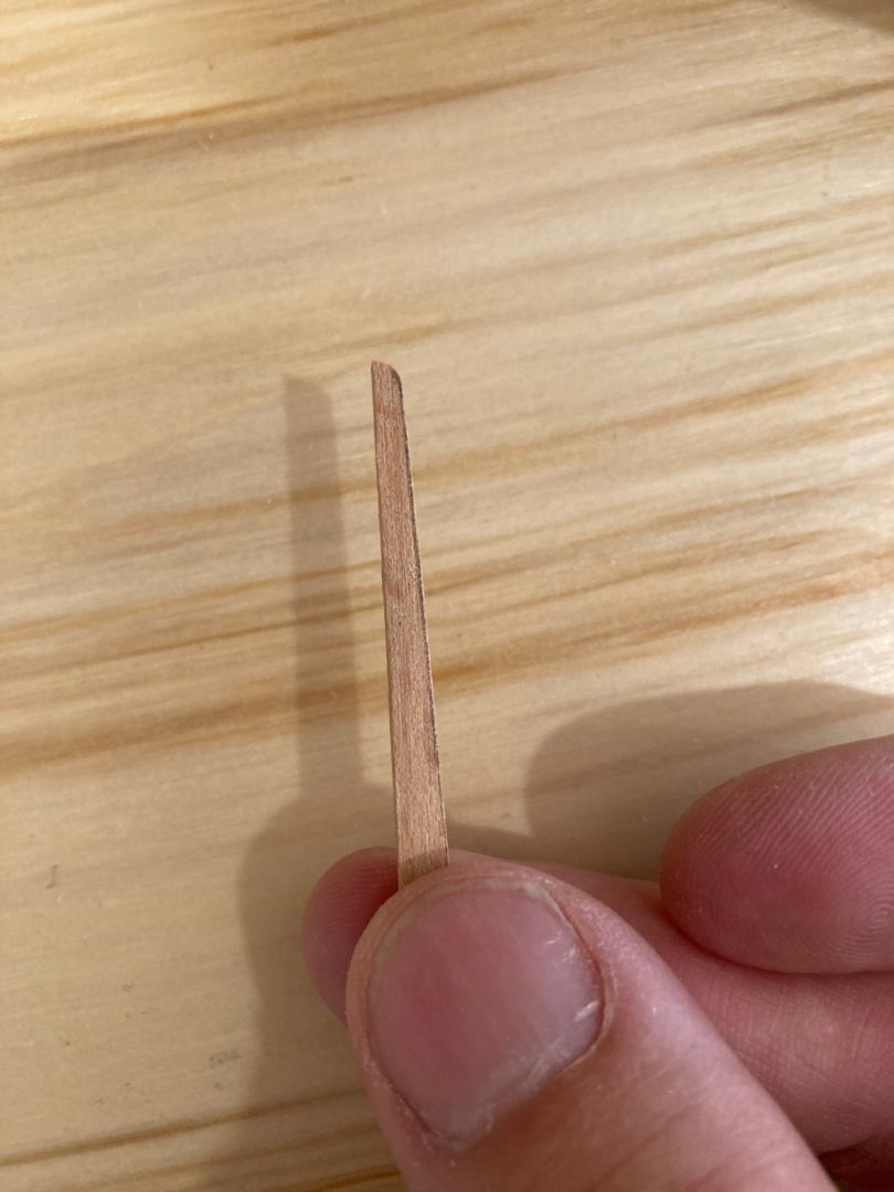
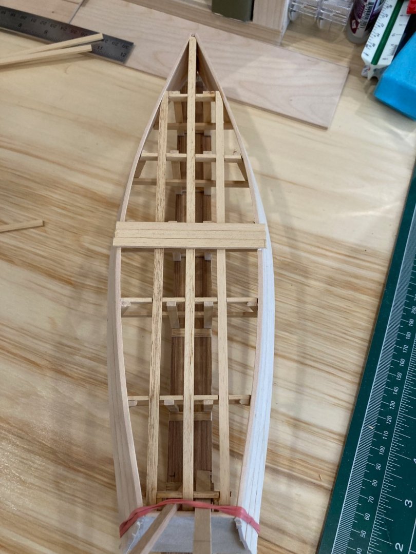
Hello all It's been a very busy and productive day in the workshop. I followed through on the .5mm inboard planking, including the inboard transom, added and finished the rubbing strakes on the bottom, and fashioned and installed the outer stem. I gave the inboard planking a decent sanding, but will do a bit more and finish them with some wipe-on poly - the photos below show them unfinished. The rubbing strakes were pretty straightforward - I made them from 1/8 x 3/32" lime, angling off the stern and bow ends as per the plans. The stem tapers in the sided dimension from 1 5/8" to 1" (full) from the head to the heel and also has a slight taper in the molded dimension. To achieve this on a relatively small strip, I glued the piece to a larger scrap of 1/4" ply (leftover from the molds) and sanded the taper in on the drum sander. It was easy to loosen the piece afterwards, clean it up and fit it to the hull. There is a flat section along the front 3/4" wide (full), which I filed in more or less....I kept misplacing my glasses all day - not sure what's happening, but I'm not quite ready to get a strap for them to hang around my neck, so for now I'll have to depend on my short-term memory improving....anyways, I think she's shaping up - I'll finish the out rails (1/8 x 1/16" half round mahogany) and start on adding the frames (1/16"x 1/16" mahogany) tomorrow - then it will just be the stringers, thwarts and in-rails to complete before the basic model is complete - unless I go for a rig....still undecided..... Enjoy! hamilton


-
Feature Suggestion
hamilton replied to CDR_Ret's topic in Using the MSW forum - **NO MODELING CONTENT IN THIS SUB-FORUM**
Aha! Thanks B.E. - much appreciated! hamilton -
Feature Suggestion
hamilton replied to CDR_Ret's topic in Using the MSW forum - **NO MODELING CONTENT IN THIS SUB-FORUM**
These arrows don't appear for me when I maximise the gallery images....so I can't navigate them - not sure why this is....I wonder if Terry is experiencing this same issue? hamilton -
Yes - I think it will look much nicer with some clean looking planking inboard - thanks for dropping bye John! hamilton
-
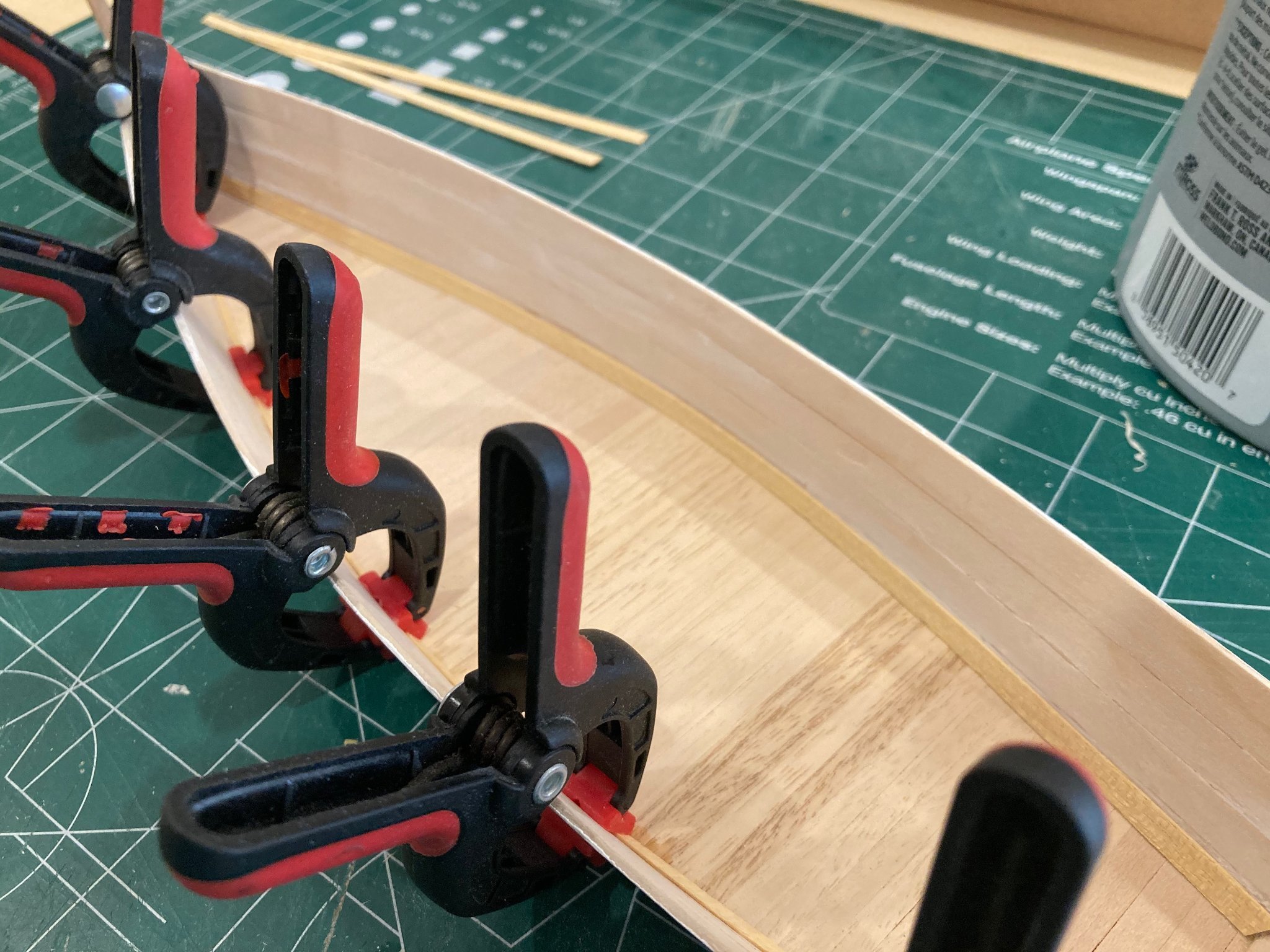
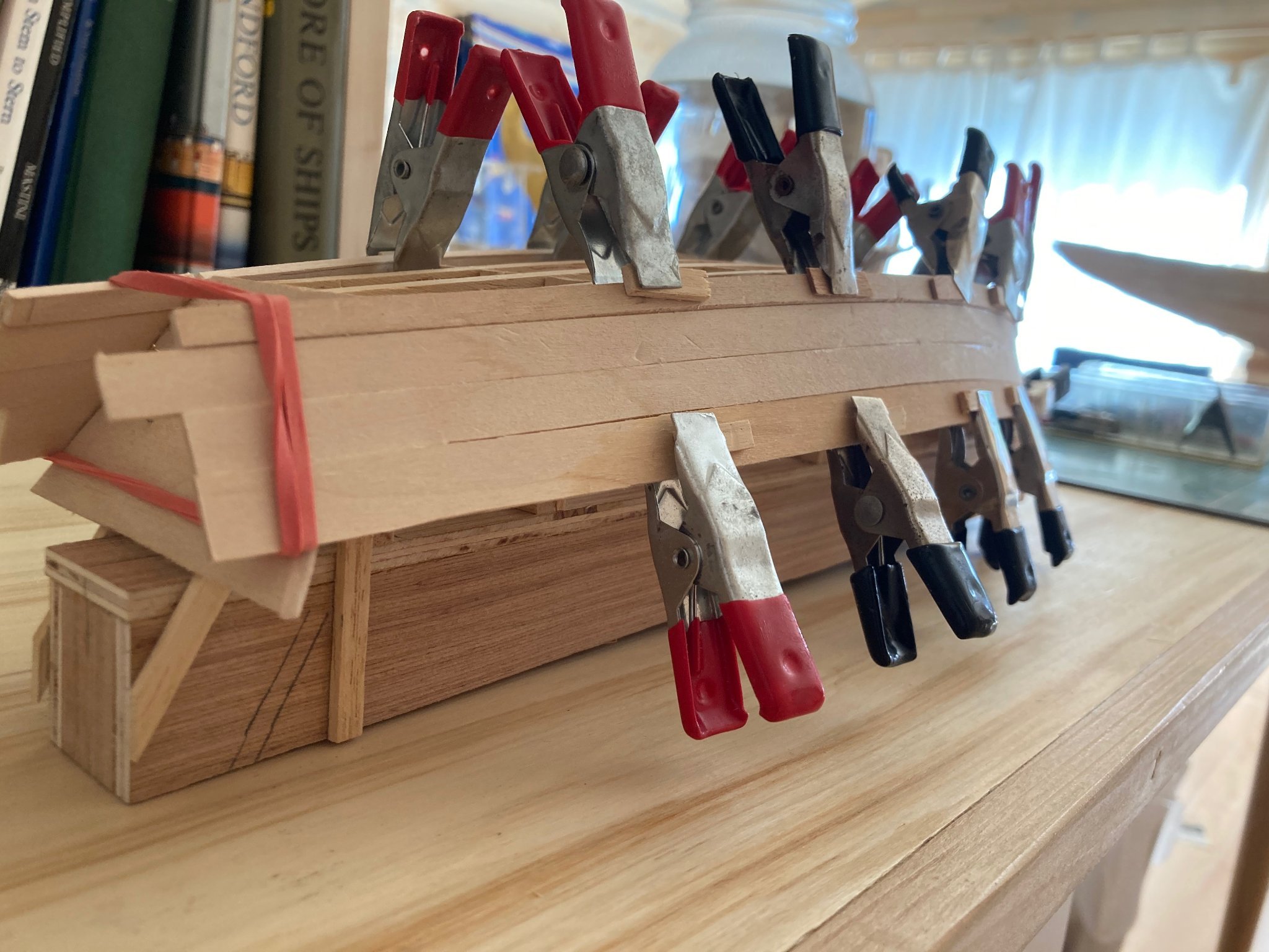
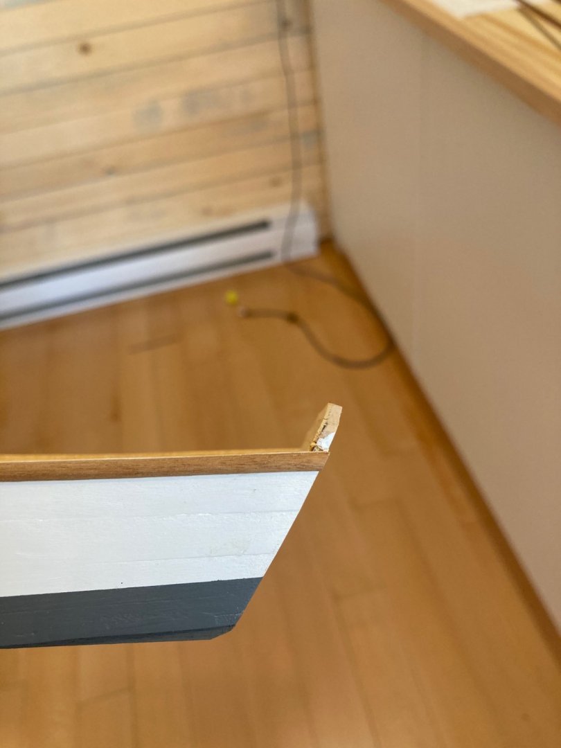
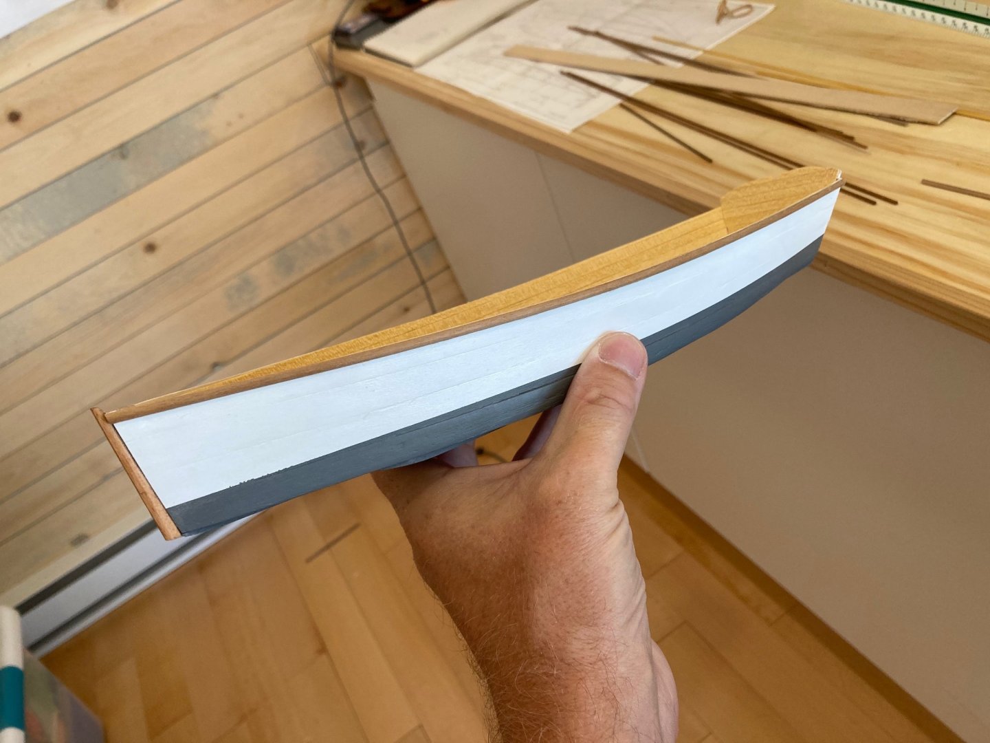
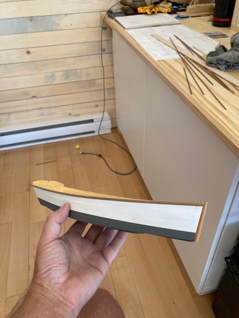
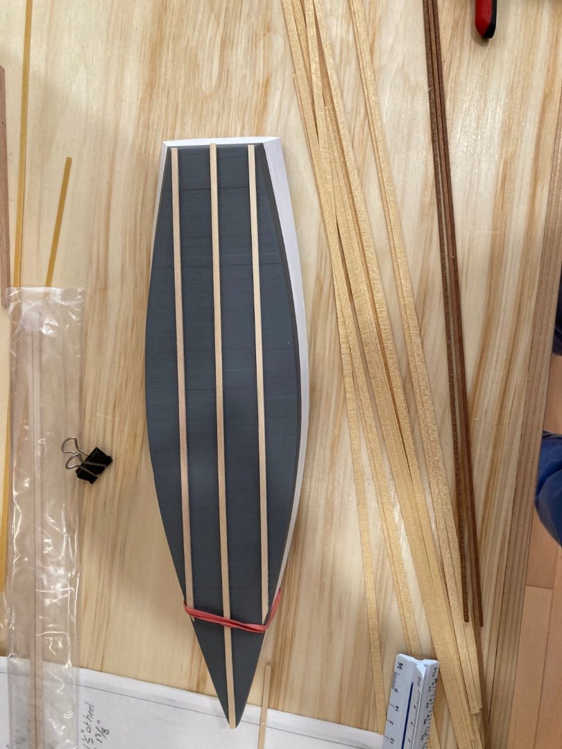
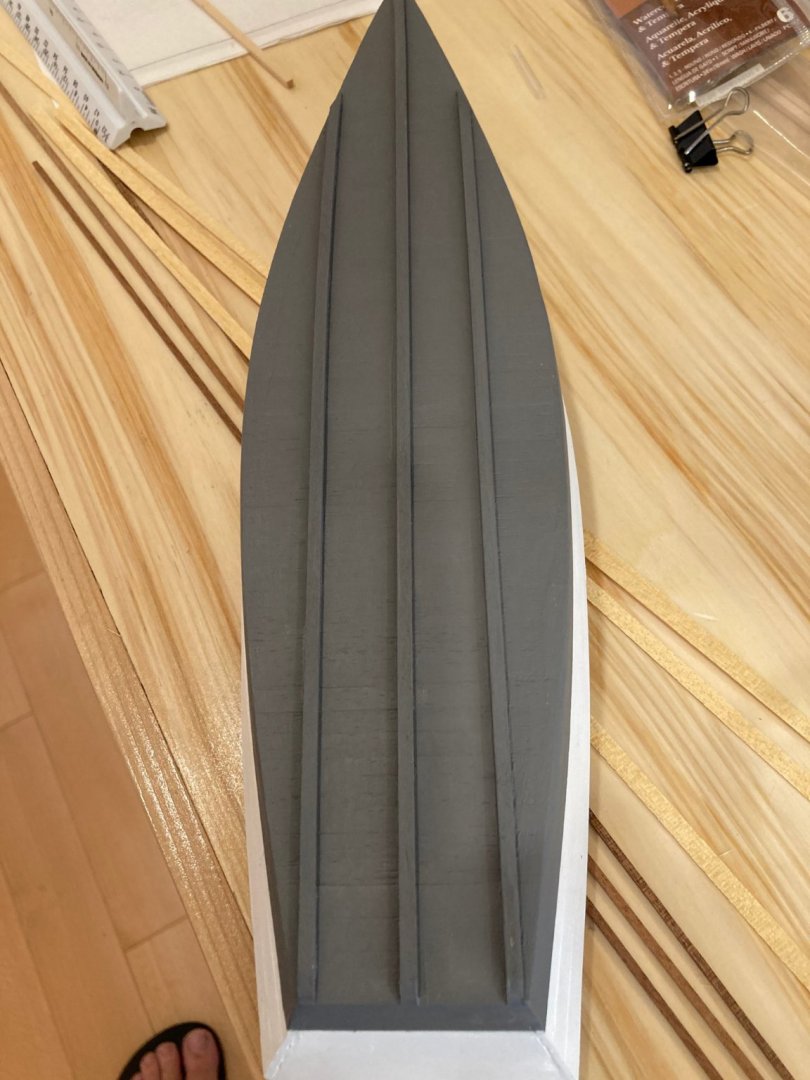
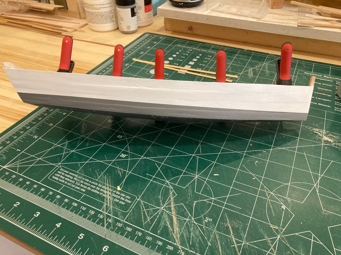
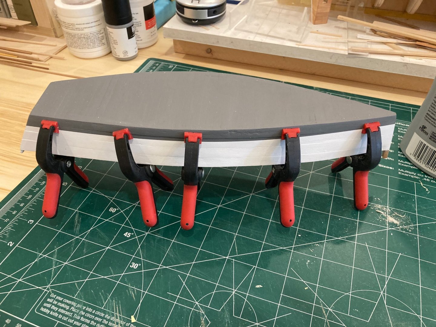
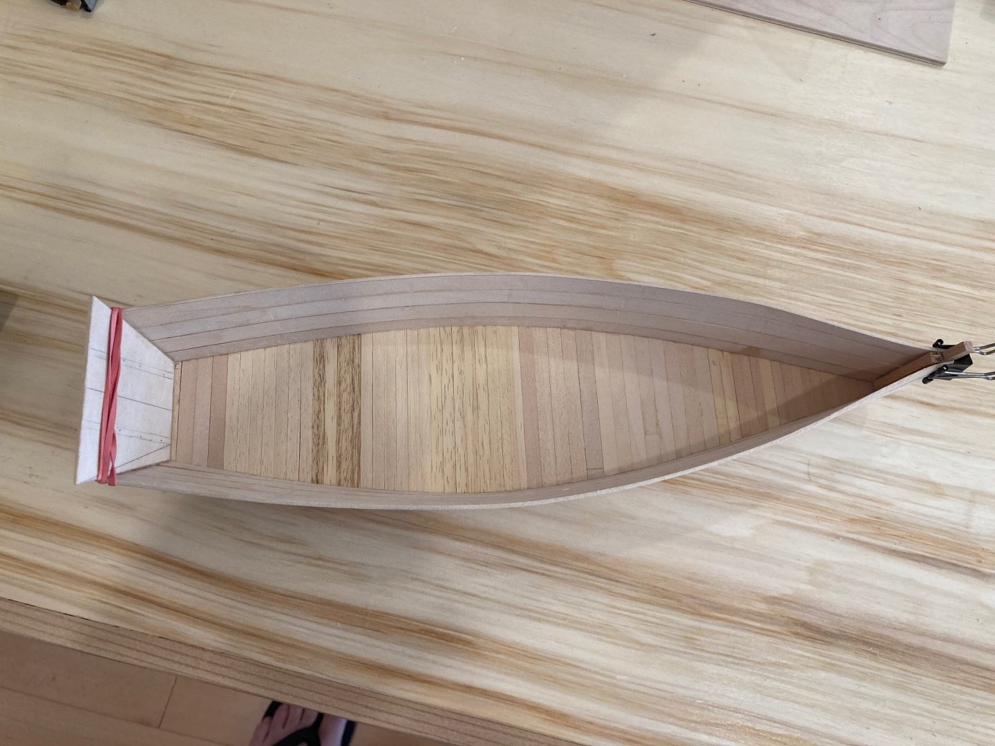
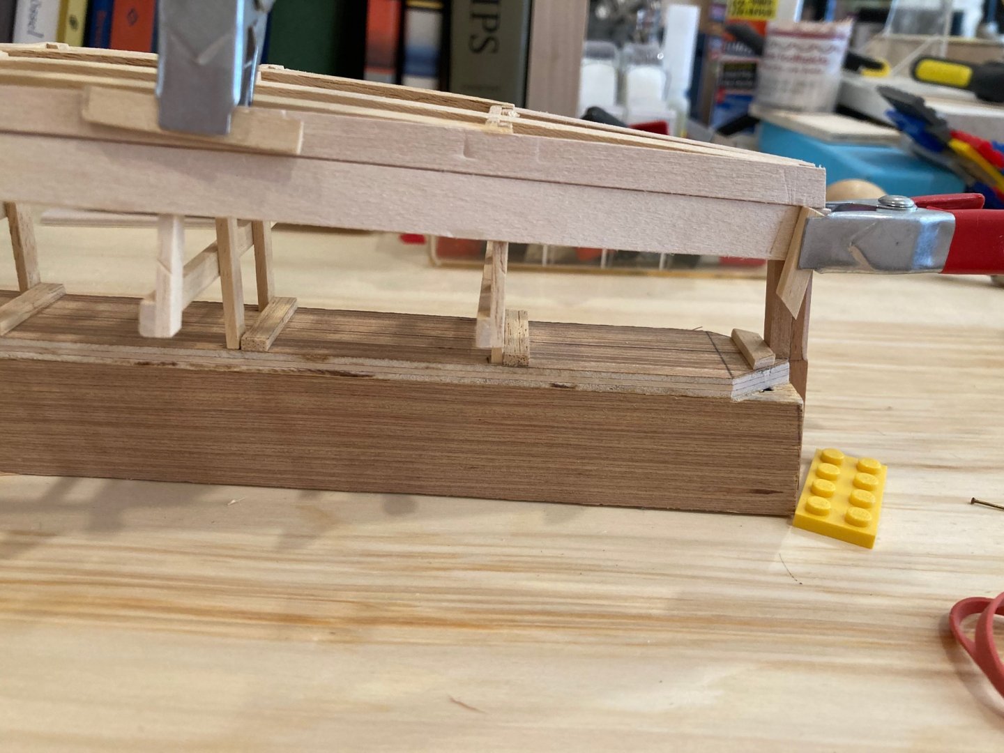
Hello again: Back from our vacation now and returned to the heat and smoke of the Pacific Northwest...mostly been doing laundry today, but had a bit of time to puzzle out some things on the OC Skiff and do some minor work. Before going away I did finish outboard - white above the waterline and a dark grey below. My main quandary at this point was the inboard finishing. I wanted to go for a natural wood finish inboard, but the filler I used to seal up some of the broader seams between planks meant that a natural finish would look a bit uneven and weird. I thought for a minute about painting, but I really didn't like that idea, so I decided to add some very thin (.5mm) planking inboard. I had quite a bit of usable material left over from my build of the Fair Rosamund so am using that - it's thin enough that it won't make the topside planking look too weighty and is a decent enough tone that a few coats of wipe-on poly should bring out a good natural finish. The final image below shows the first strake of inboard planking set on the starboard side and clamped in to port. Enjoy - hope you're all doing well out there. hamilton

-
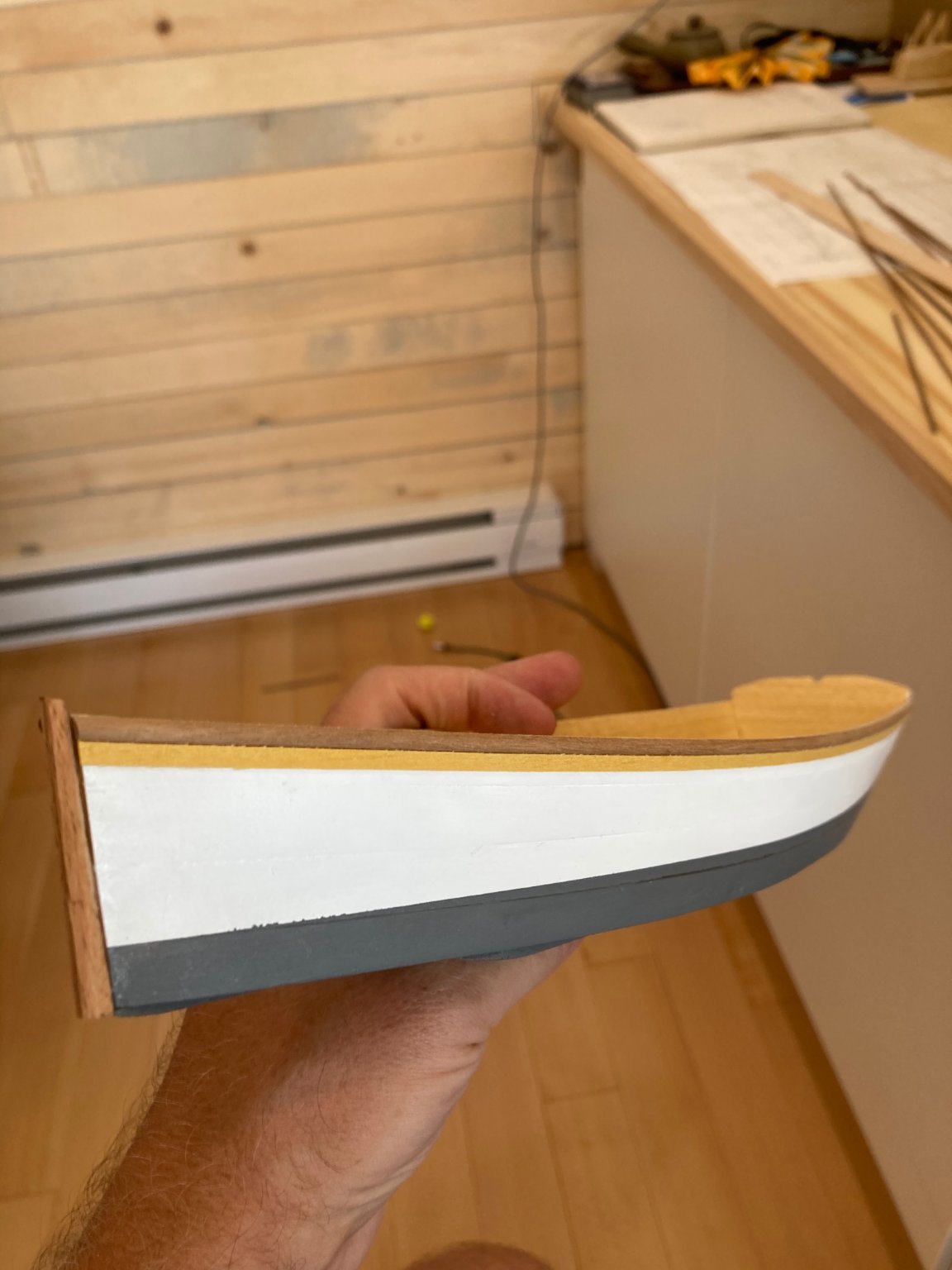
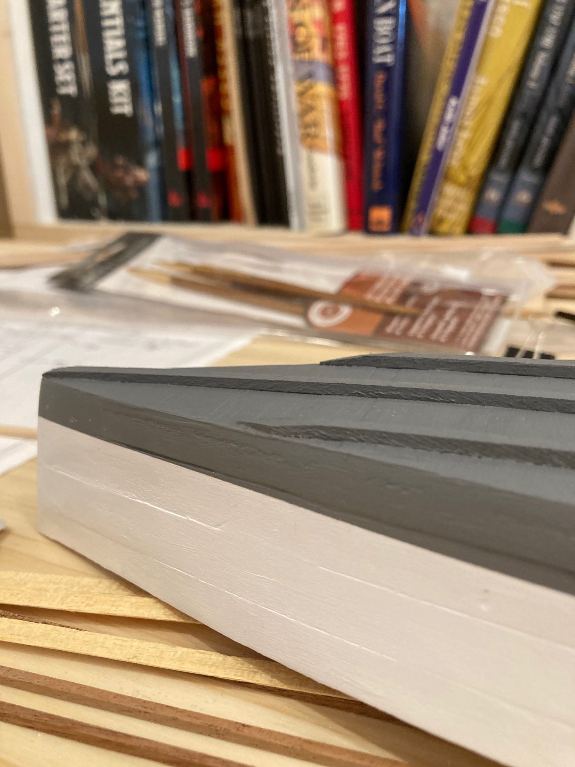
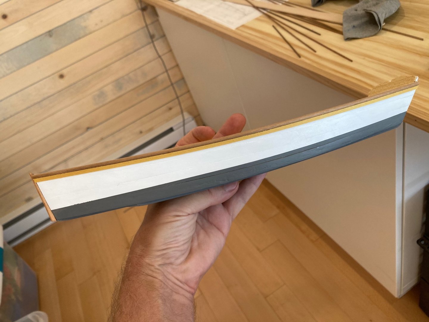
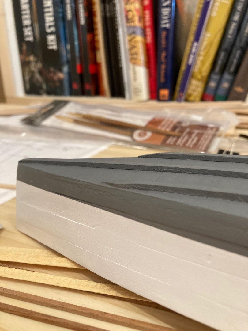
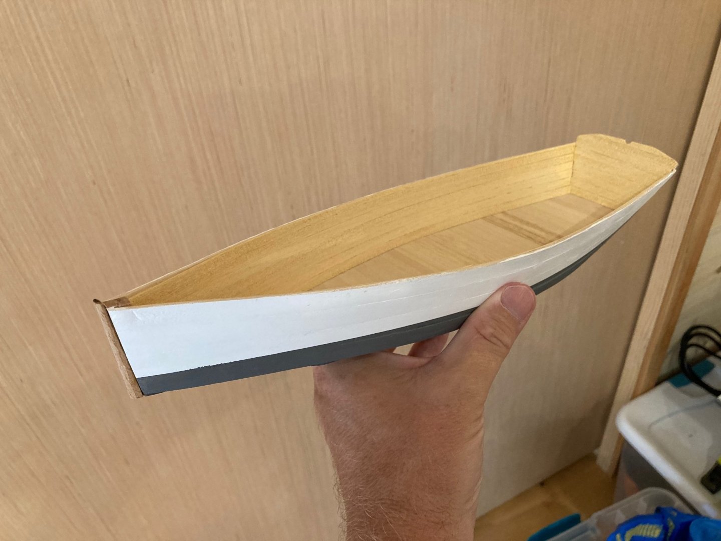
Hello all Quick update (without photos, I'm afraid). I spent a bit of time filling the small and not so small errors in the topside planking and sanding the hull quite a lot inside and out in preparation for finishing. I'm still undecided on the interior, whether to paint it white (to hide my mistakes) or use a stain for a wood finish (as would suit the actual skiff). I used a bit of acrylic wood filler inboard and these places will really stand out in a harsh way with a wood stain...but I could subject the inboard areas to more rigorous sanding and maybe reduce the offensiveness.... The outboard finish is more straightforward. I applied three coats of primer to the outboard planking, transom and bottom and then masked off the waterline. Below the waterline I've put two coats of neutral grey, and the upper hull will be white. I found some nice half round mahogany about 1/8" wide and 1/16" think that will serve as the outside rail, and left natural. I will then put a very thin (1/64") strip of pre-painted walnut leftover from way back in my Blandford days - this will provide a nice accent with the wood against the white hull. In any case, this last work is not yet complete, but we're leaving on vacation tomorrow morning until Aug 12 - so nothing happening here till then...kind of don't want to take a break, which is a good sign...feeling that same eagerness to move forward that is familiar from prior to my accident, so I'm quite happy about that....when I return, I'll finish painting outboard, do some staining tests and make a final decision about inboard finish, then add the rubbing strakes to the bottom and start on the frames inboard.... Sorry no photo update this time! But more will follow when we're back. Bye for now - stay cool if you're in a hot zone like we are! hamilton
-
Wow - the time, trouble and revision was definitely worth it - for these result and I imagine for all the other frames you'll have to assemble! Looking forward to watching this one come together - I saw another one of these from an MSW member and can't recall who, unfortunately (sorry to you if you're reading this!) and it builds into a really nice model. Have fun! hamilton
-
Thanks all for this feedback! Ron - these pictures are very clarifying in terms of the lug rig set-up - especially for the downhaul. Spyglass - that link is also extremely useful - I guess I didn't dig deeply enough during my own searches!! Thanks again all for the info! hamilton
-
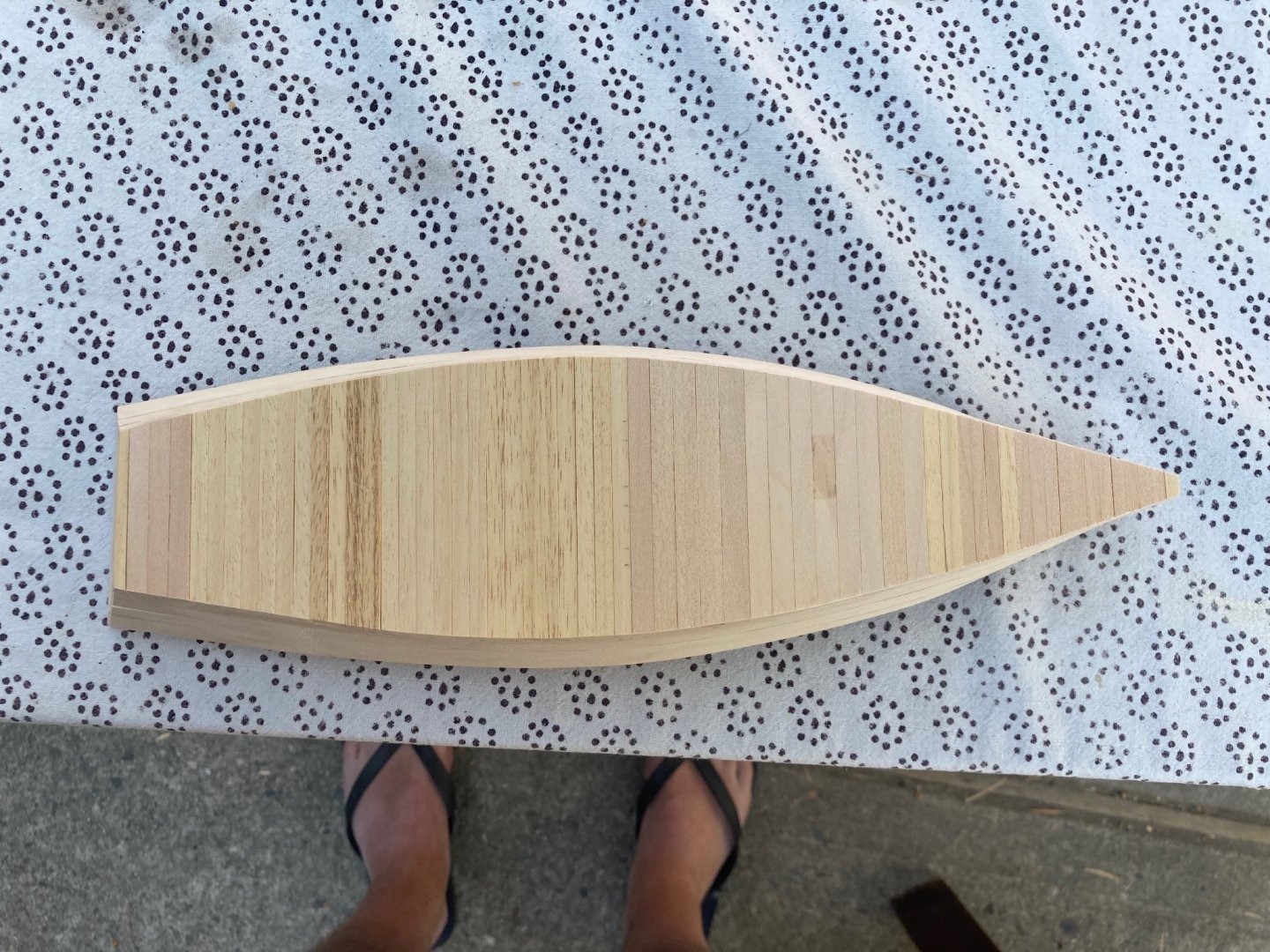
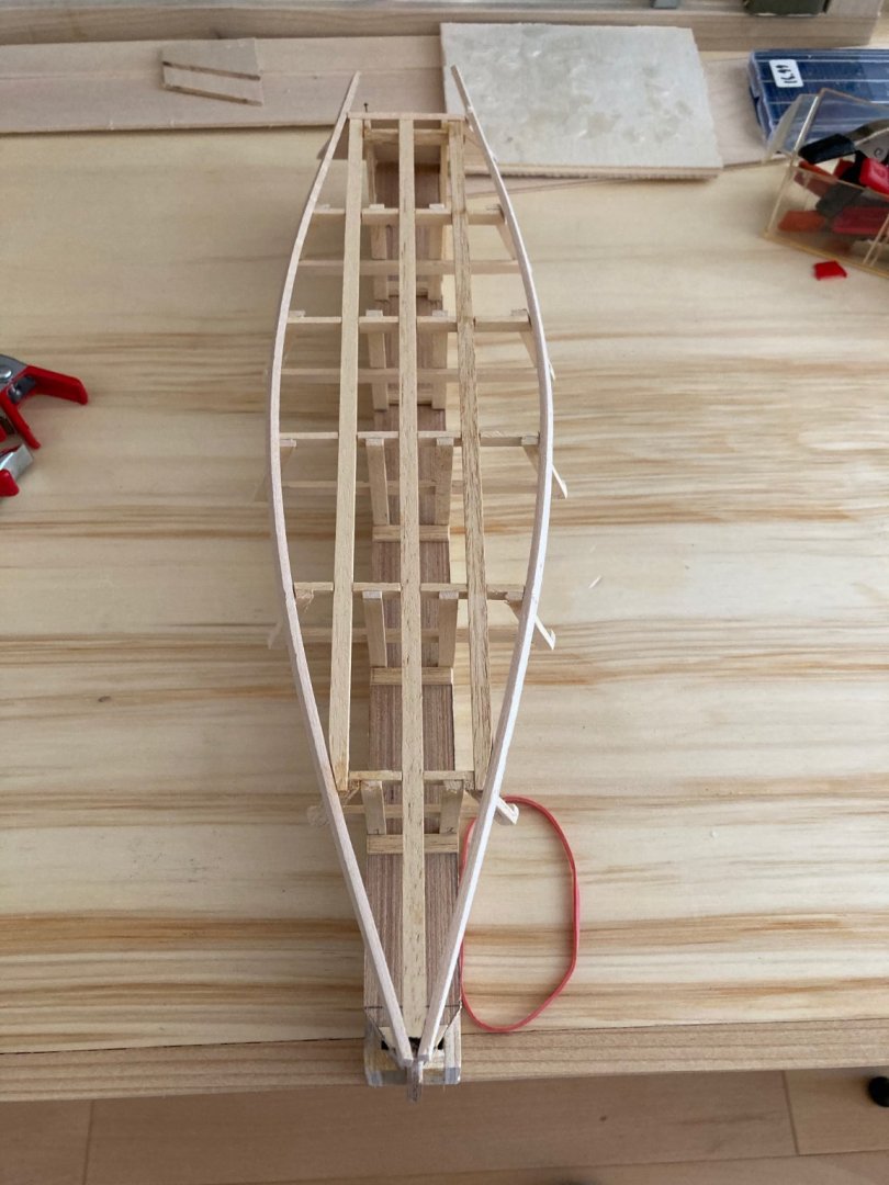
Is this the post that will push this log onto page 2? I'm always curious....(edit - it wasn't!) In any case I've now finished the bottom planking, done some preliminary cleaning up of the hull and taken her off the molds. The next step will be to fashion three rubbing strakes for the hull bottom and then finish the interior and exterior. Initially I wanted to leave the interior natural, but I'm skeptical about whether I can get a nice wood finish with the materials I'm using. So I'll likely finish both inboard and outboard but keep a natural finish for the frames, stringers, rails, thwarts and forward covering board. This will also help hide some of the defects in the hull - you'll see (if you haven't already) that there is a bit of filling to do here and there.... The last bit of work I did today was to add some shape to the transom and file out a sculling slot along the centreline. It's occurred to me that if I'm going to add a rig to this skiff I'll need to add a stern post and rudder....but this can wait a bit until after the previously described steps are complete.... in any case, enjoy the pics and bye for now hamilton

-
Thanks Alan and Spyglass! Very helpful descriptions/photos. I'll see what I can do once the time comes to consider a sail arrangement. Thanks again! hamilton
-
Hi there: I'm wondering if anyone has any resources on how to set up a lug rig for a small vessel - this is in relation to a current small build I've got going of a 14' rowing skiff. I saw an image of it adapted for sail with a lug rig, but as hard as I've tried to examine images of this rig, I haven't been able to find many details on the set-up...any assistance or resources on this would be greatly appreciated. Thanks in advance hamilton
-
Thanks John - if the full sized build is as straightforward as the scale one, then it may indeed be a future prospect... hamilton
-
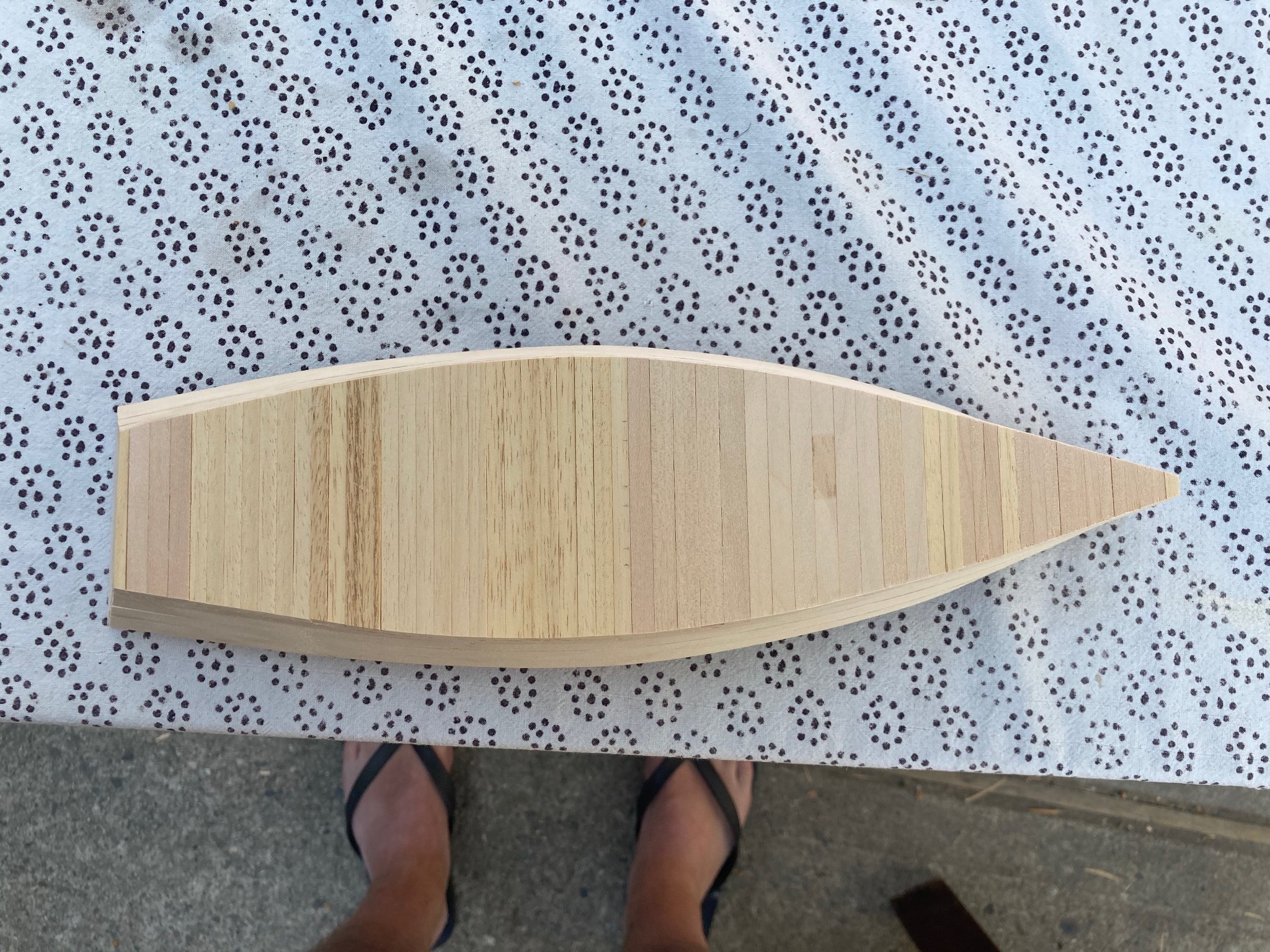
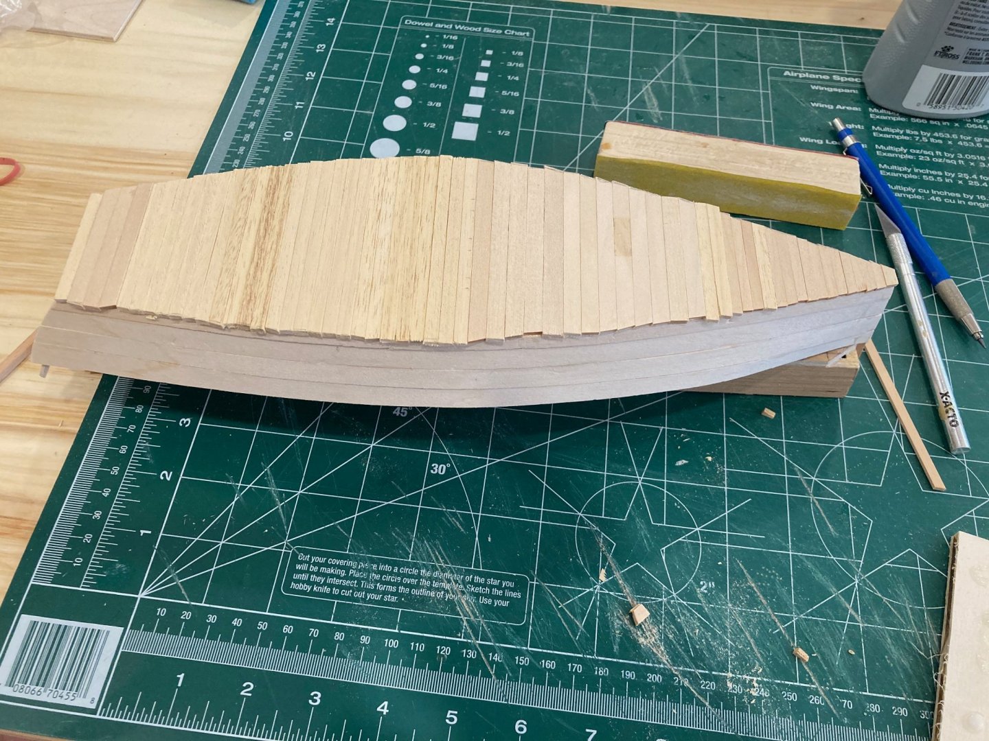
The topsides of the OC Skiff are now planked - three strakes plus garboard port and starboard - not difficult, though I had to reposition (and re-glue) a couple of the planks a couple of times. And of course you'll see that hull looks a bit scarred up from misplace or slipped clamps and other little knicks and dings sustained in the work process. A bit of filler and a lot of sanding and shaving will soon follow to neaten this up. And the exterior hull will be painted, so much of these marks, gaps, etc. will eventually blend in. I've now started laying out the bottom planking. Working with leftover materials from previous build has meant that I'm using planks of a consistent thickness (3/32") but of varying widths (3/16-1/4"). I could have taken a bit more time to achieve consistency here, but I figured that this will not be too noticeable when the model is displayed. We're heading out of town this coming weekend for our annual cabin getaway, but I'm hoping to be close to finished this model by the time we head out - unless, of course, I decide to add a rig. I saw some images of this boat carrying a lug rig, but I've not been abler to find any images of how this rig works, whether I would need to add shrouds or stays, or how some of the running rigging (specifically the downhaul) would be set up....Any resources any of you might have on such a rig would be very helpful and much appreciated! In the meantime, enjoy the photos. hamilton


-
HMS Euryalus 1803 by rlb - 1:48 scale
hamilton replied to rlb's topic in - Build logs for subjects built 1801 - 1850
Hi Ron - can you teach me how to be as careful and precise as you are? As with your Oneida log I really appreciate the explanations and descriptions you provide of your process. I always learn a lot reading through your logs. Very impressive work here hamilton- 122 replies
-
- 5
-

-
- Euryalus
- Plank-on-frame
- (and 4 more)
-
Thanks Mark - it feels good to be back! hamilton
-
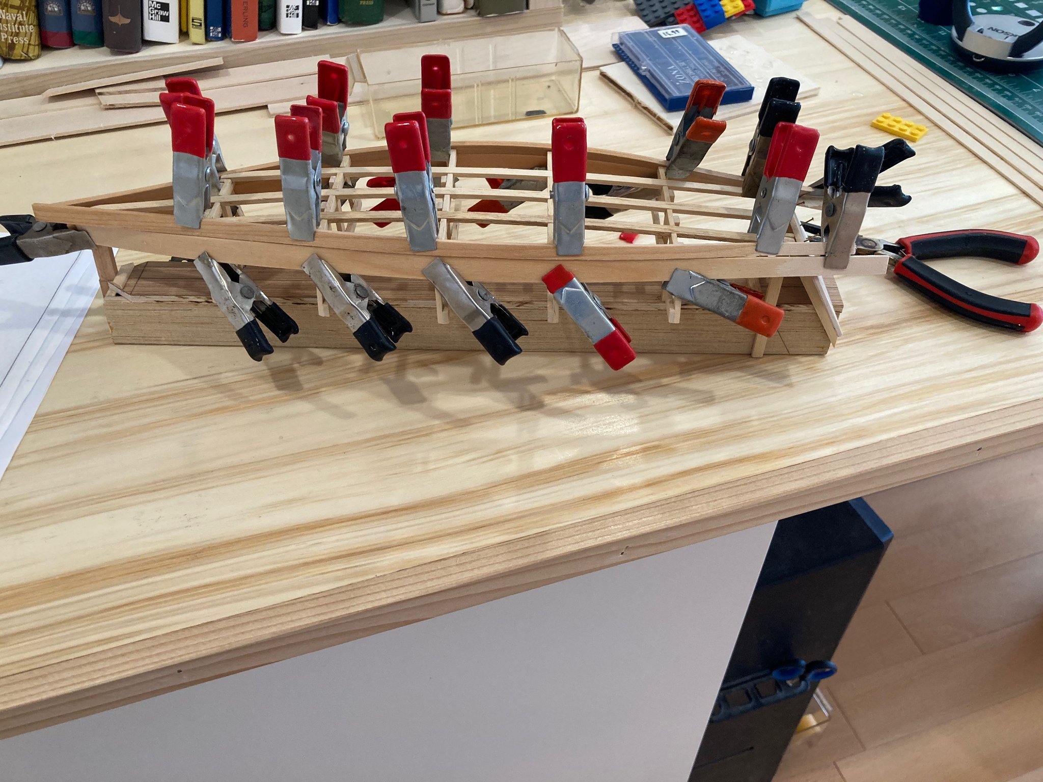
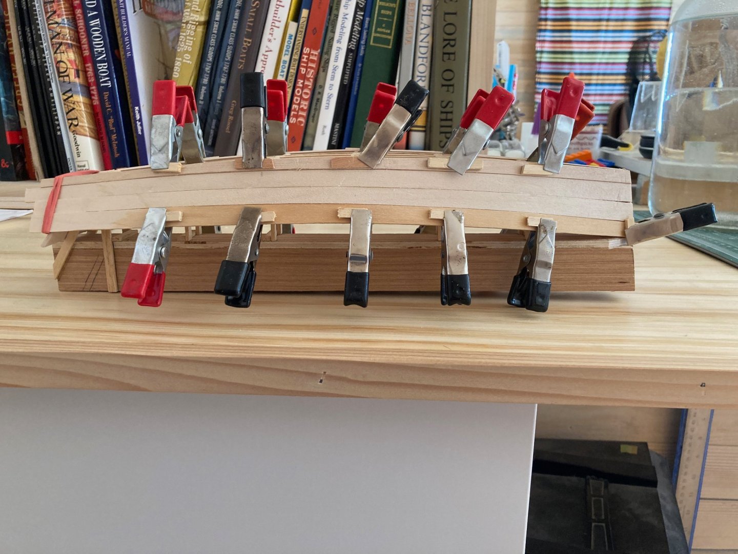
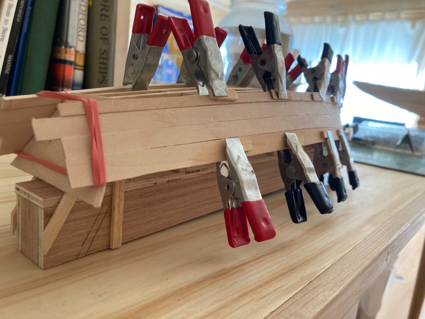
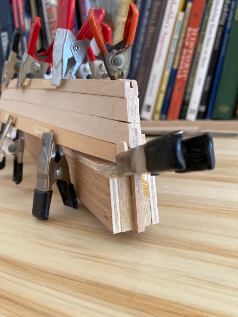
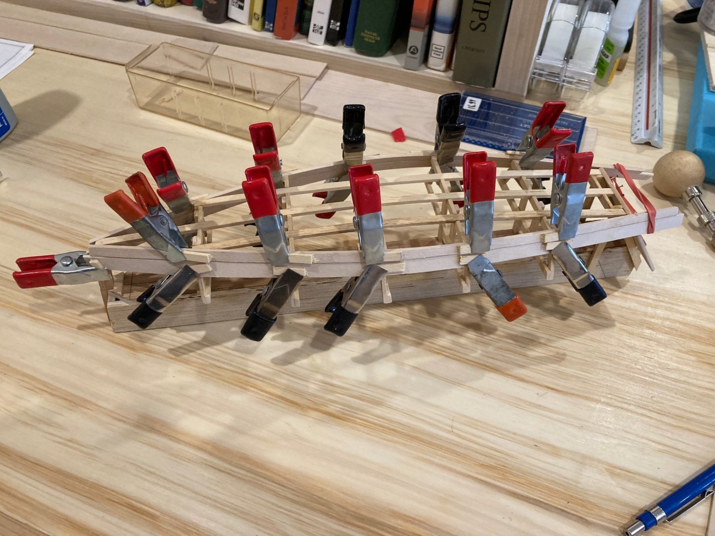
And here she is with the first side plank fit, bristling like a porcupine......another plank tomorrow and (if I can get an hour) the last one on Saturday. Then on to doing some refining work on the garboard and planking the bottom. I'll add some rubbing strakes in line with the ribbands on the building molds and then she'll be ready to be flipped over and attention paid inboard - this will no doubt be the fastest model I have ever made! Though I may see if I can whip up a sailing rig for her despite lack of plans, details or any particular knowledge of how this might work practically on a boat such as this! Enjoy! hamilton

-
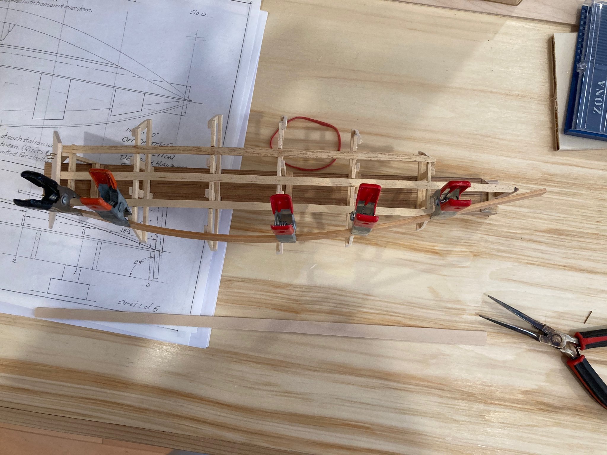
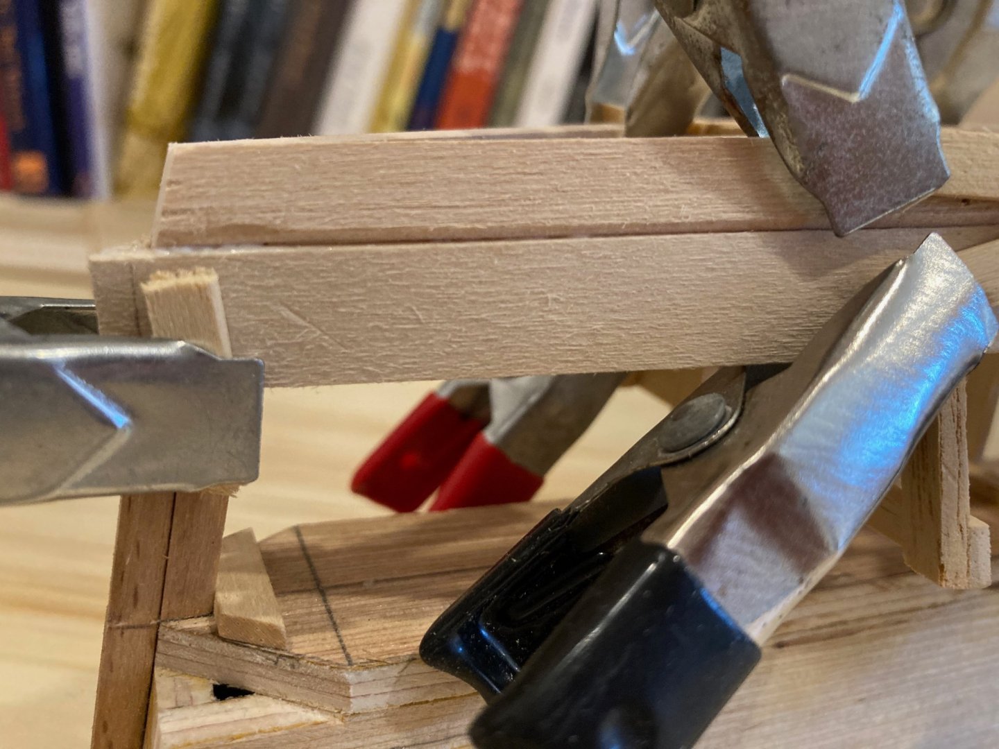
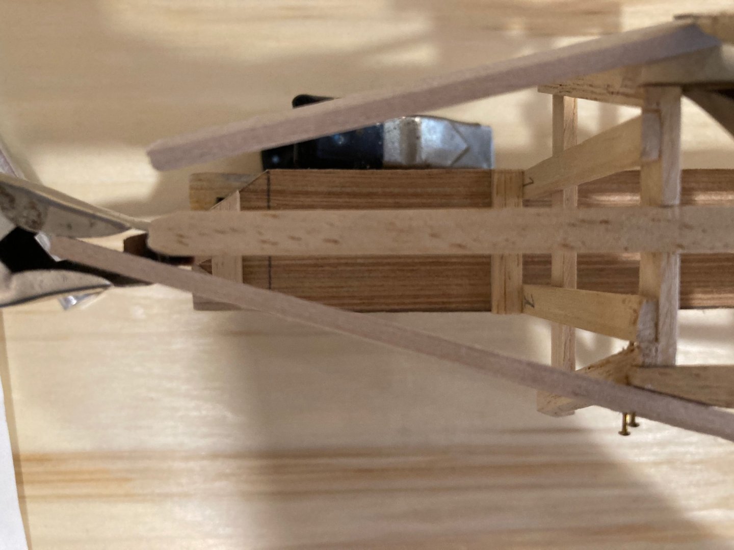
Yeah Ron it was very hard to tolerate for a while, but I thought that if I could work out how to do it once I could do it again with this minor impediment. And now for a small update on the OC Skiff. I've fit the garboard strakes now and am ready to move on to the remainder of the side planking after a bit more prep work is complete. I've already milled and tapered all the side planking (3/64" lime cut to 5" and tapered to 4" in a straight taper) but a few things need to be done to prep. The first strake above the garboard needs a slight chamfer along the back edge to make a tight joint with the garboard plank. Also - and this is contrary to all planking I've done on other models, the planks are wider at the stem than at the transom - the taper running back from fore to aft. It took me a while to figure this out as my instinct was to imagine that planks usually taper towards the bows. In any case, like the garboard, the planks will be installed over-long and trimmed/sanded down to fit. In the end, the fitting of the garboard strake was very touchy, mostly because it is only fastened at the stem and transom. On one side I inserted brass nails to hold the plank in place (as you'll see in some of the photos - but this process soon appeared unnecessary, and I reverted to clamping the planks to the molds to hold the position. I'll have to retain these clamps until the side planking is complete - removing them probably as I proceed through the bottom planking. This is to prevent the "drift" of the planking in the vertical dimension - though maybe this isn't necessary? Couldn't hurt I suppose... Anyways, here are some photos of the garboard plank attached - side planking will proceed (slowly) over the coming days - probably going to do one strake each side every day - but since there are only three strakes it's not much bother! Enjoy! hamilton

-
Thanks for the comments and votes of confidence Ron and John. Ron - yes the injury was a real bummer, but I've learned to adapt around it. The hardest thing is that I have not, until quite recently, been able to play the guitar - but in the last year I've knuckled down and brought myself close to where my abilities were prior to the accident - this is actually one of those achievements that has re-oriented me to modelling, as well. John - yes, the whole series is well worth the watching - it's a very good practical guide to the various stages of construction and it is amazing to see these kids hard at work fitting planks, planing, and caulking the hull! I only wish I had grown up in an environment like that. hamilton
-
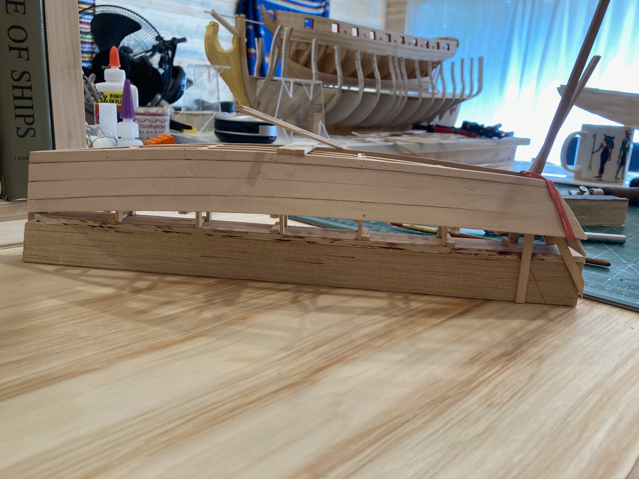
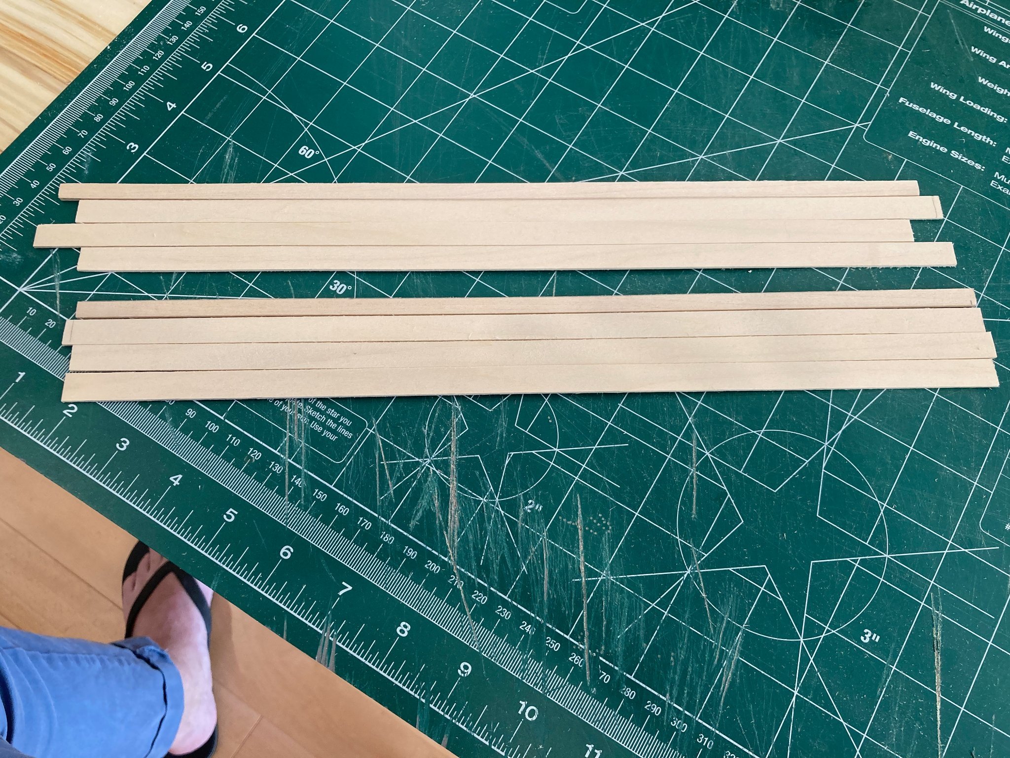
With the fitting of the transom, the model is now ready for the side planking. The planking of the full-sized skiff consists of a thicker (7/8") garboard strake and three strakes of topside planking (9/16"). Fudging the numbers a little bit, I'm using 3/32" basswood for the garboard and 3/64" basswood for the topside planking. The width of the garboard planking tapers through its length from 3-1/4" to 2-5/8" (full) in a straight taper - no spiling!! The topside planks also have a straight taper from 5" to 4" (full). I milled some 3-1/4" (and a bit) strips from the 3/32" basswood sheet and some 5" strips (and a bit) from the 3/64" sheet. Tapering these was pretty easy, using a 24" straightedge and going in repeated light moves on the tapering line. I'm not quite sure about the use of basswood for the planking - it seems that there is certainly an opportunity to use nicer hardwoods and to produce a nice natural finished model. I do have a supply of boxwood and some scraps of other exotic hardwoods from previous builds, but I'm saving the boxwood for a special project and I don't have the other woods in dimensions I need....so I will likely be painting the exterior, staining and varnishing the interior and using hardwoods for the frames, rails, thwarts and so forth.... In any case, after cutting and tapering the planks I had to start wrestling with the question of how to fit them. In full-sized construction, the strakes are screwed temporarily into the molds, with these holes being re-used later to attach an interior frame. This isn't really an option for me at this scale, at least not in the same way. I'm still considering the best way to fit the strakes, but I have thought of two options - would be very happy to hear any thoughts on either or both of these.... 1. Do the same thing as I did with the transom - that is, temporarily pin the strakes to the molds, and then carefully edge-glue the strakes as well as fixing them to the transom and inner stem. Theoretically, the planking should hold together and then I can simply remove the pins and lift the hull off the molds....."theoretically".... 2. Glue the strakes to the molds, as well as edge-gluing them. Then, when it's time to turn her over, I will cut the molds off at the base of the verticals and then gently pry and detach the molds. This seems likely to result in some damage to the interior planking of the boat - but this may not matter much, since frames will be added to cover where the molds were previously attached.. Anyway, again - thoughts on these (or other) possibilities are most welcome I did soak the garboards and the first strake of topside planks and they are now clamped and drying on the molds - and this is where I've come to in the process so far, so will be considering the planking over the next day or so....Photos follow. Enjoy! hamilton


-
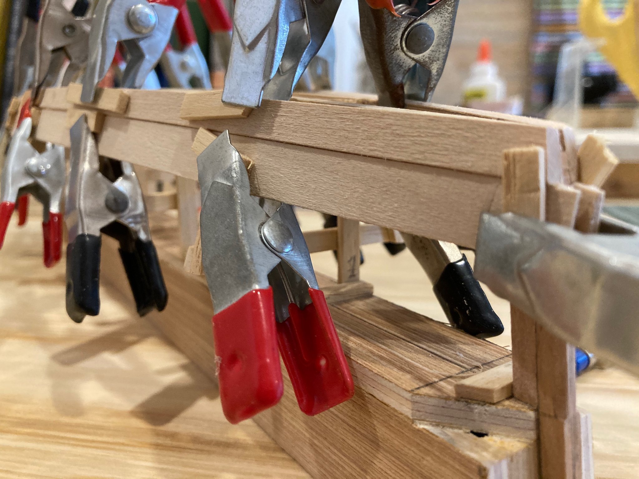
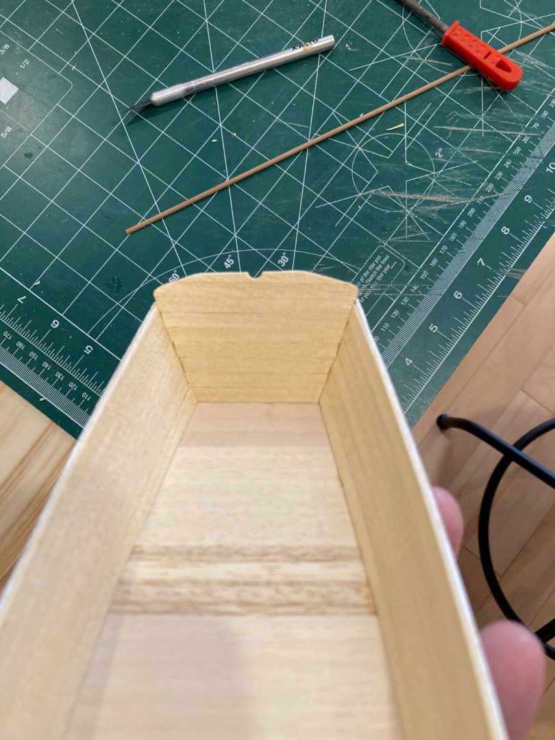
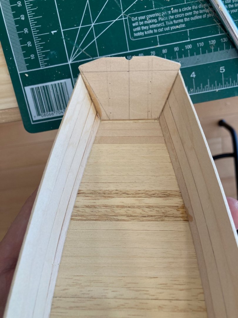
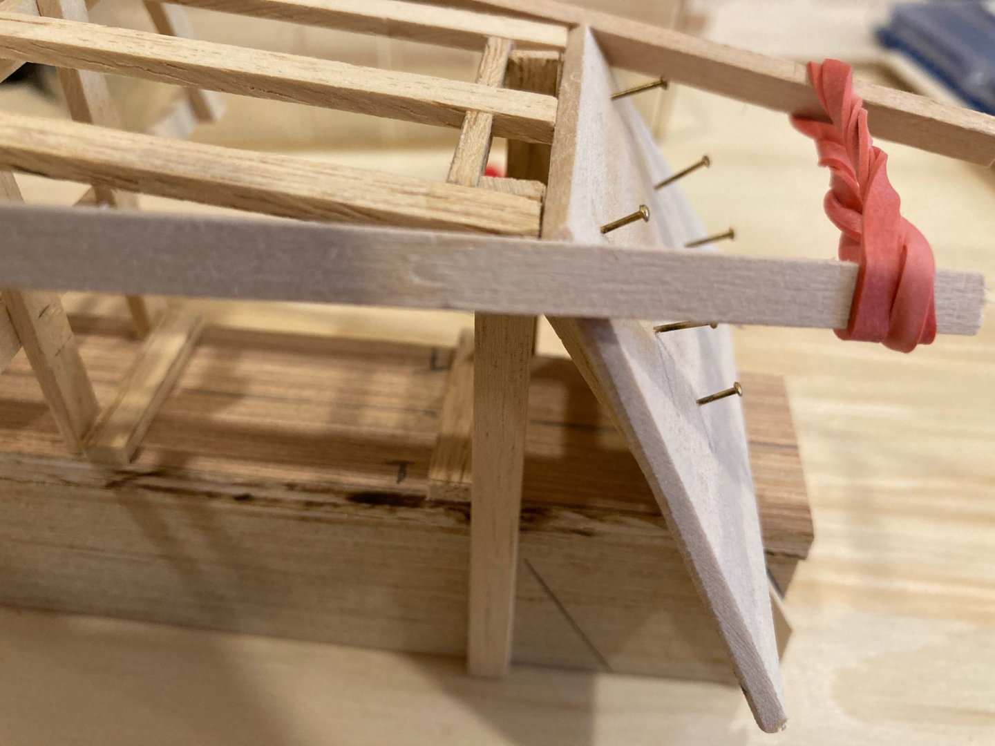
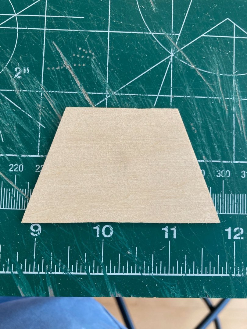
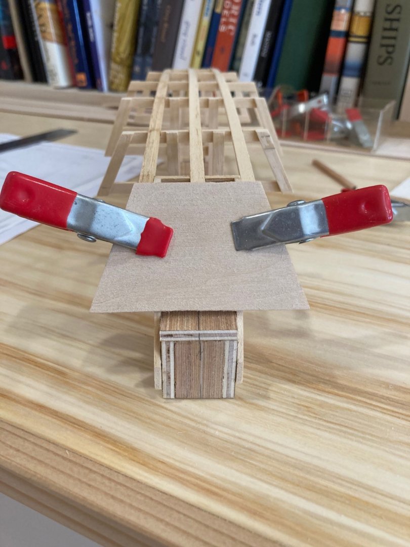
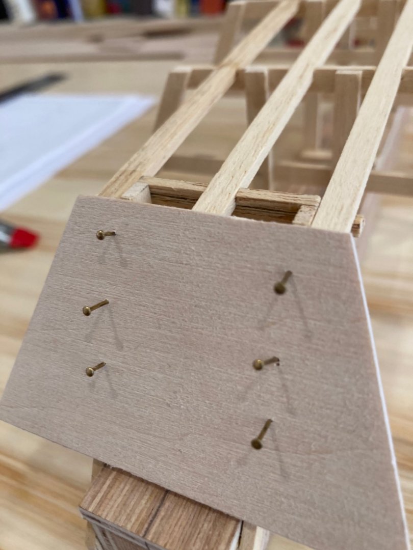
The transom was pretty easy to make. In the full-sized skiff it is built up out of edge-glued lumber, but I had some 3/32" basswood sheeting lying around that was perfect for the purpose, so I simplified things for the model. Offsets were taken from the plans and transferred to the basswood sheet. I then rough cut it and sanded it to final shape. The mounting of the transom turned out to be a bit tricky, though I think it also introduced me to a technique that will be used for the side planking and garboard strakes. The transom needs to be stable in its mounting to the transom frame, but it can't be glued on, since the boat will need to be removed from the skeleton at some point. I marked a centreline on the transom piece and used this as reference for dry mounting the transom on its frame. Once clamped in place, I marked the outlines of the angled transom frames on the inside of the transom itself. I then pre-drilled holes in the marked out areas and into the transom frame supports. I then tacked the transom in place using the small brass nails that come with every model kit (and that I have only ever used very sparingly).... Here are some images showing how this went. Enjoy! hamilton
-
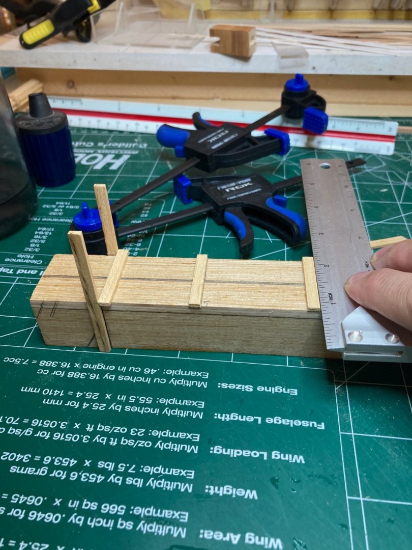
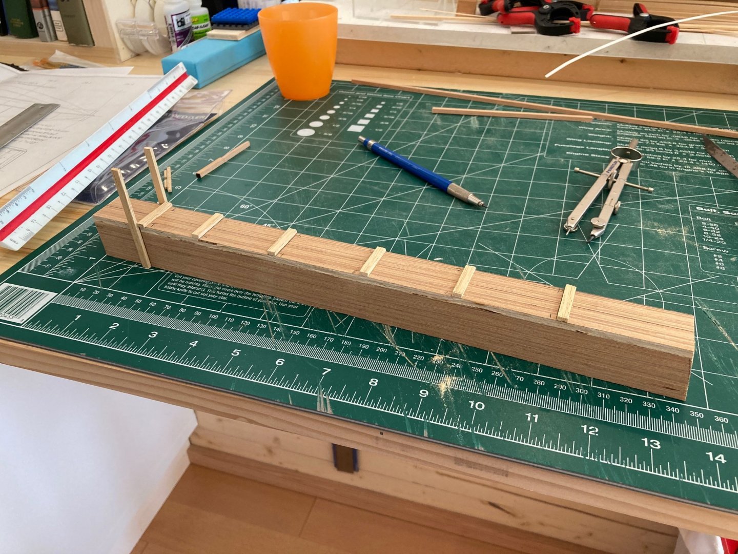
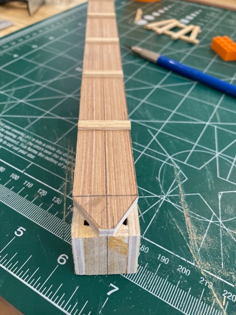
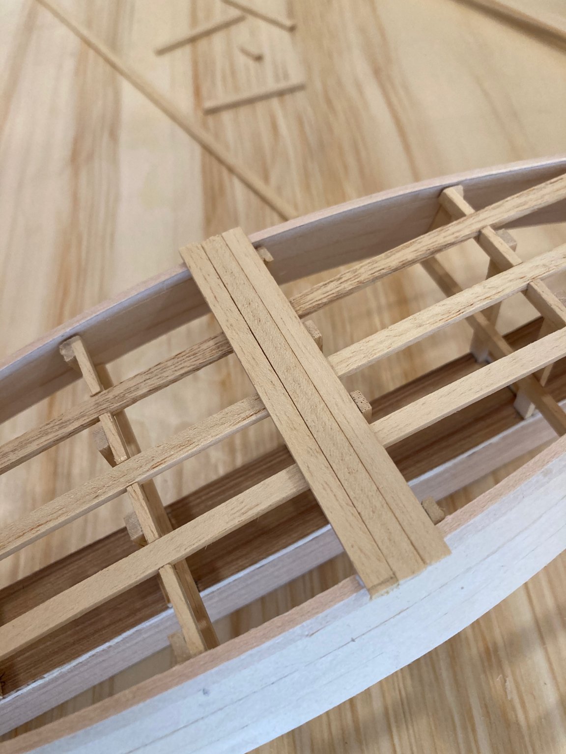
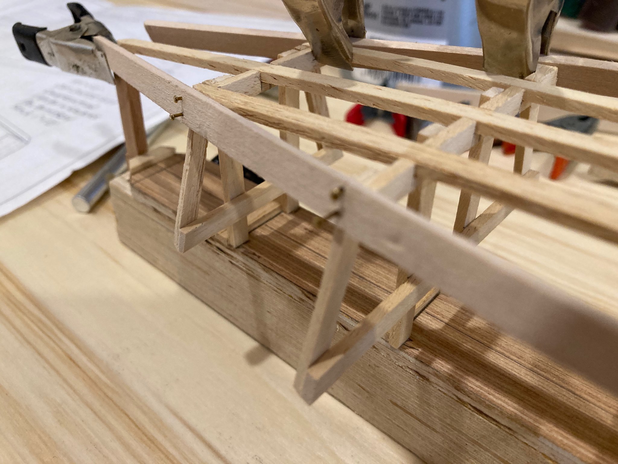
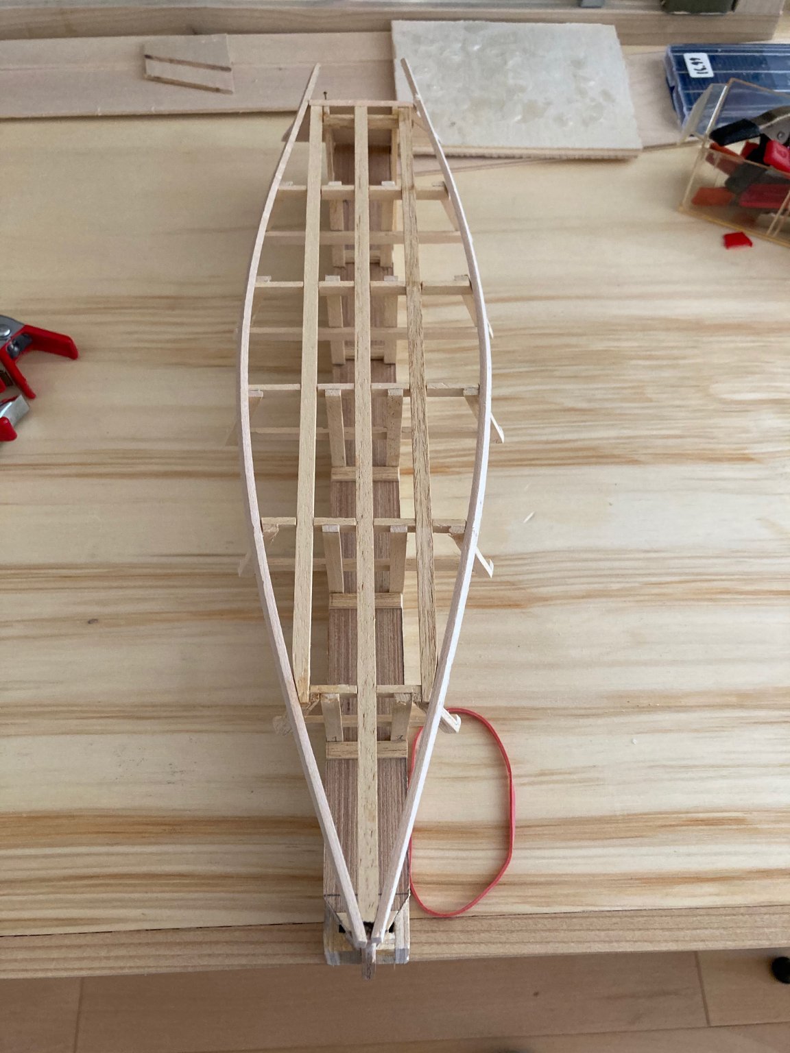
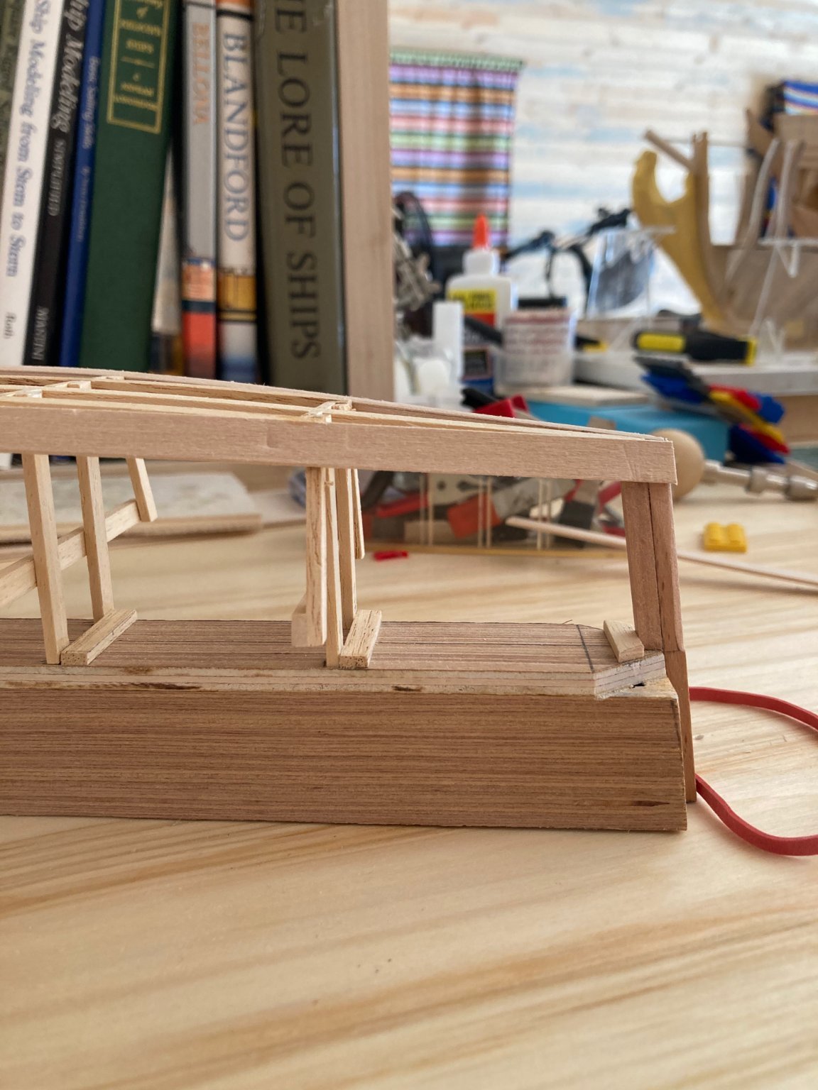
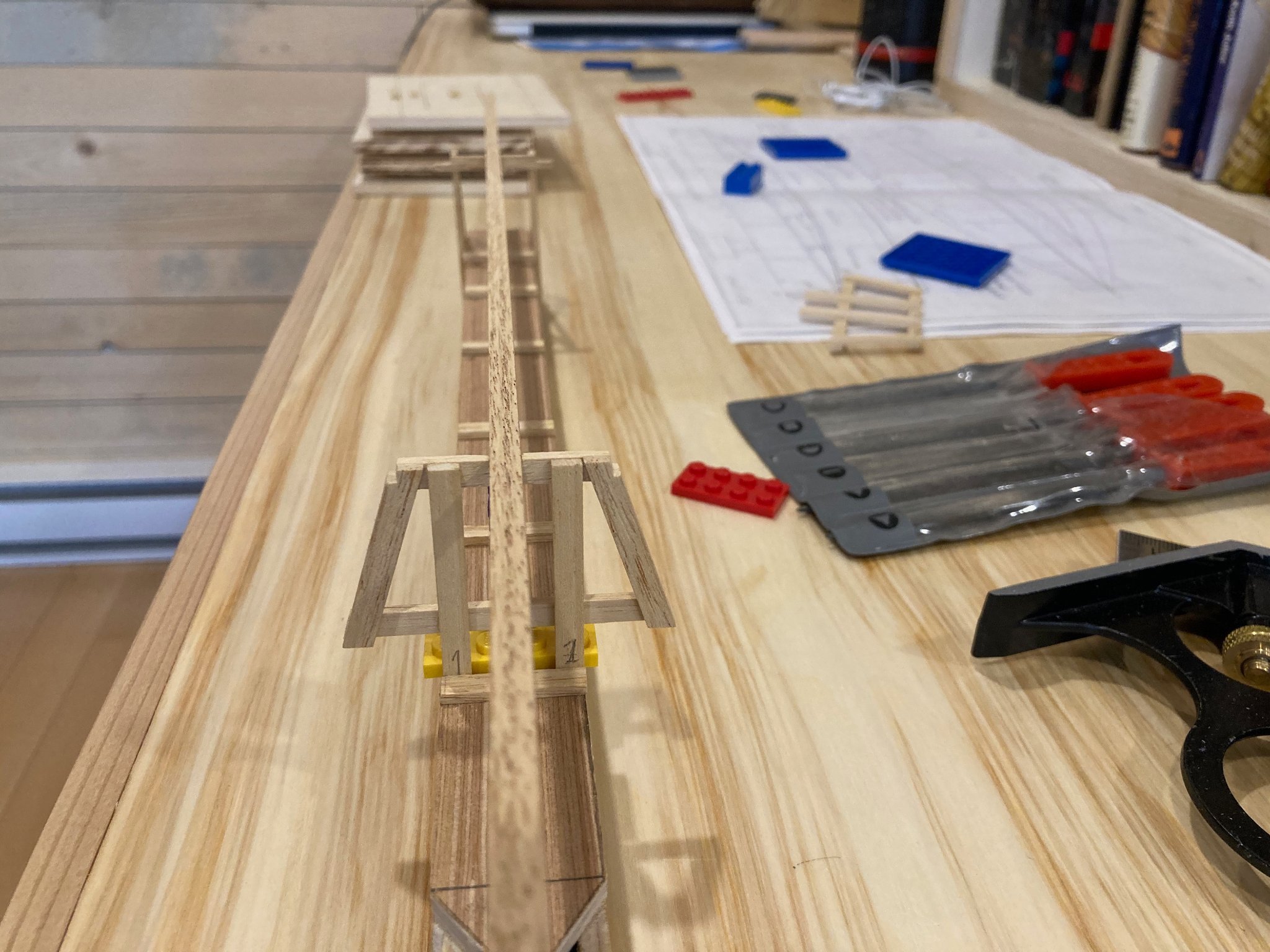
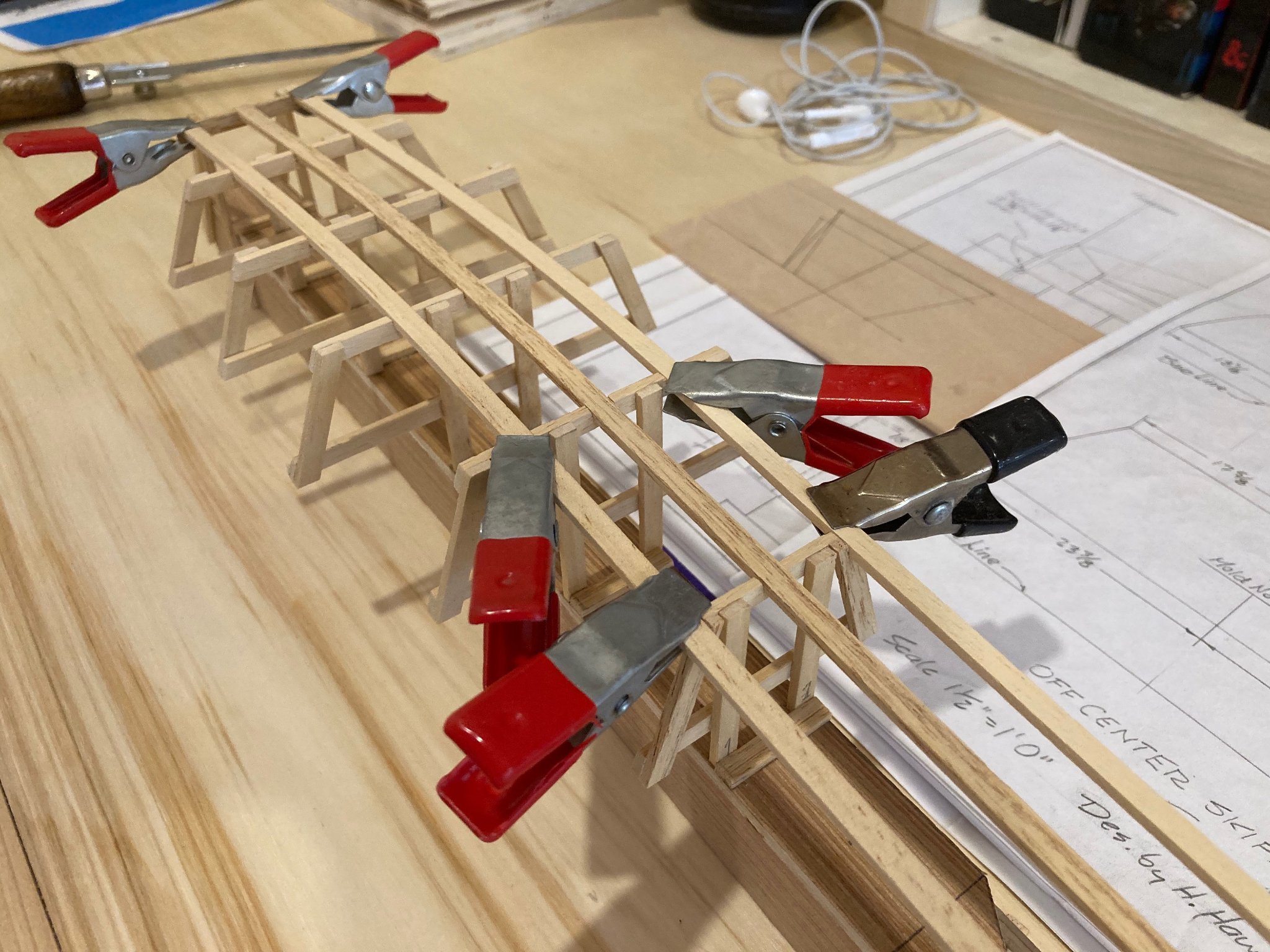
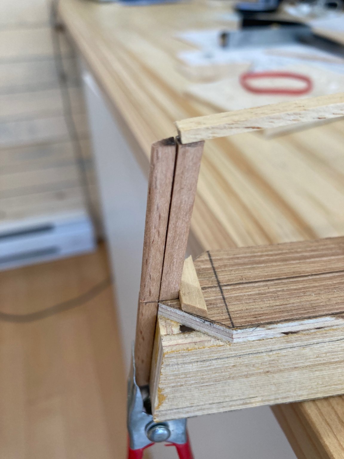
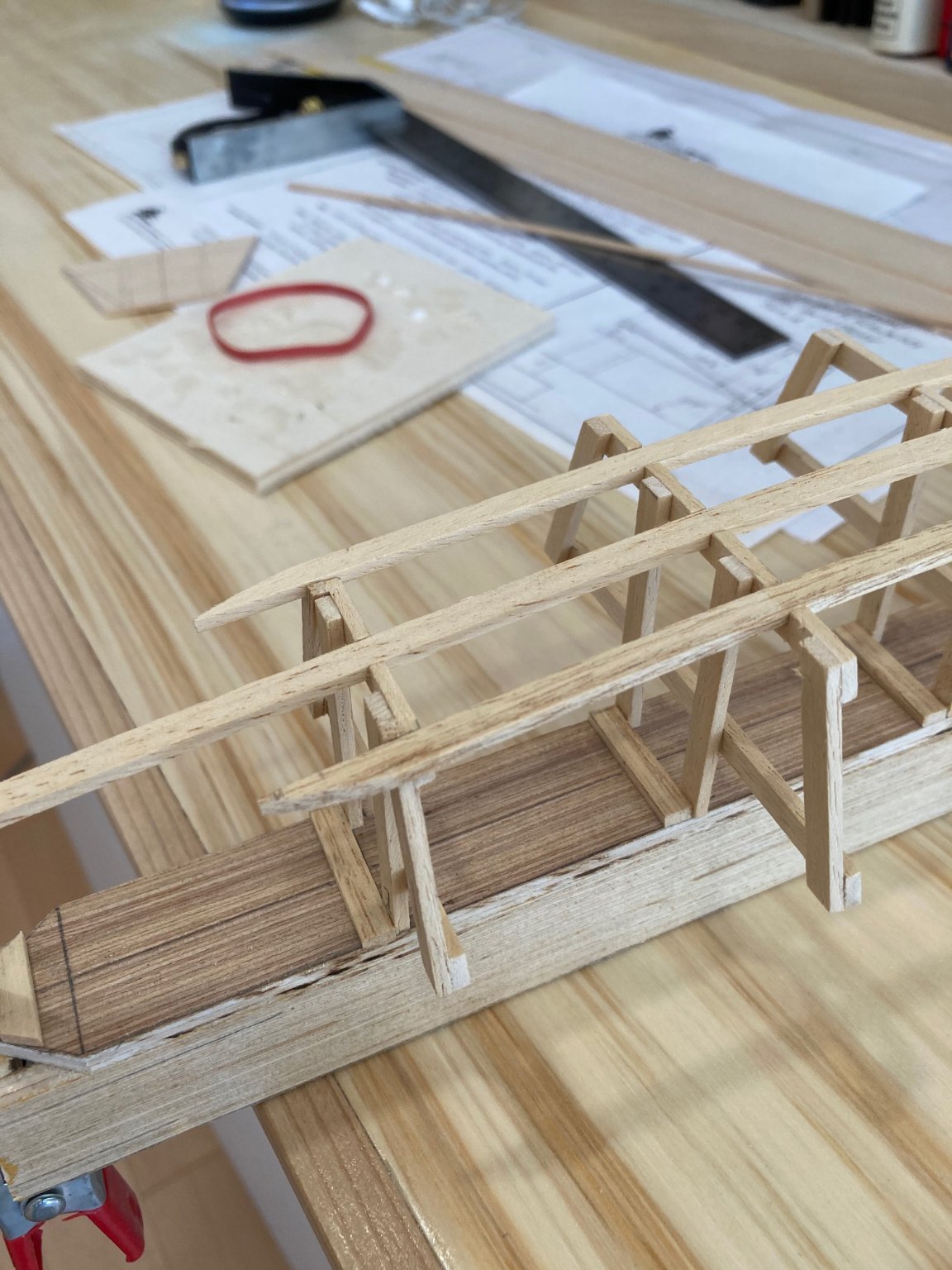
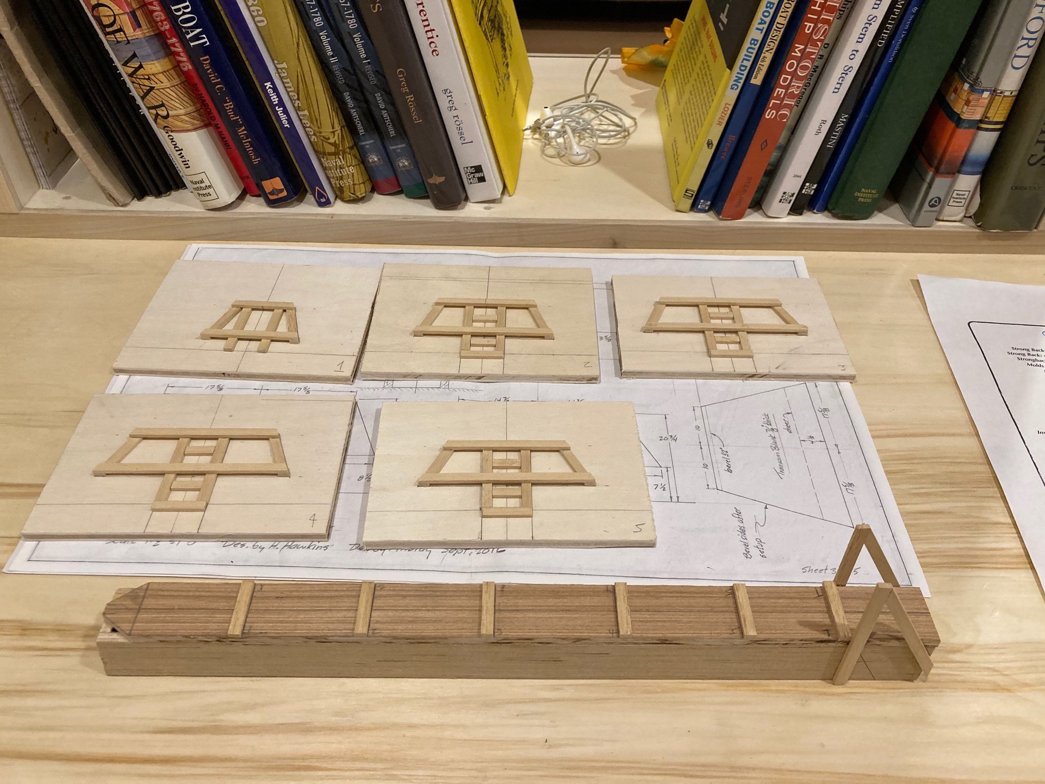
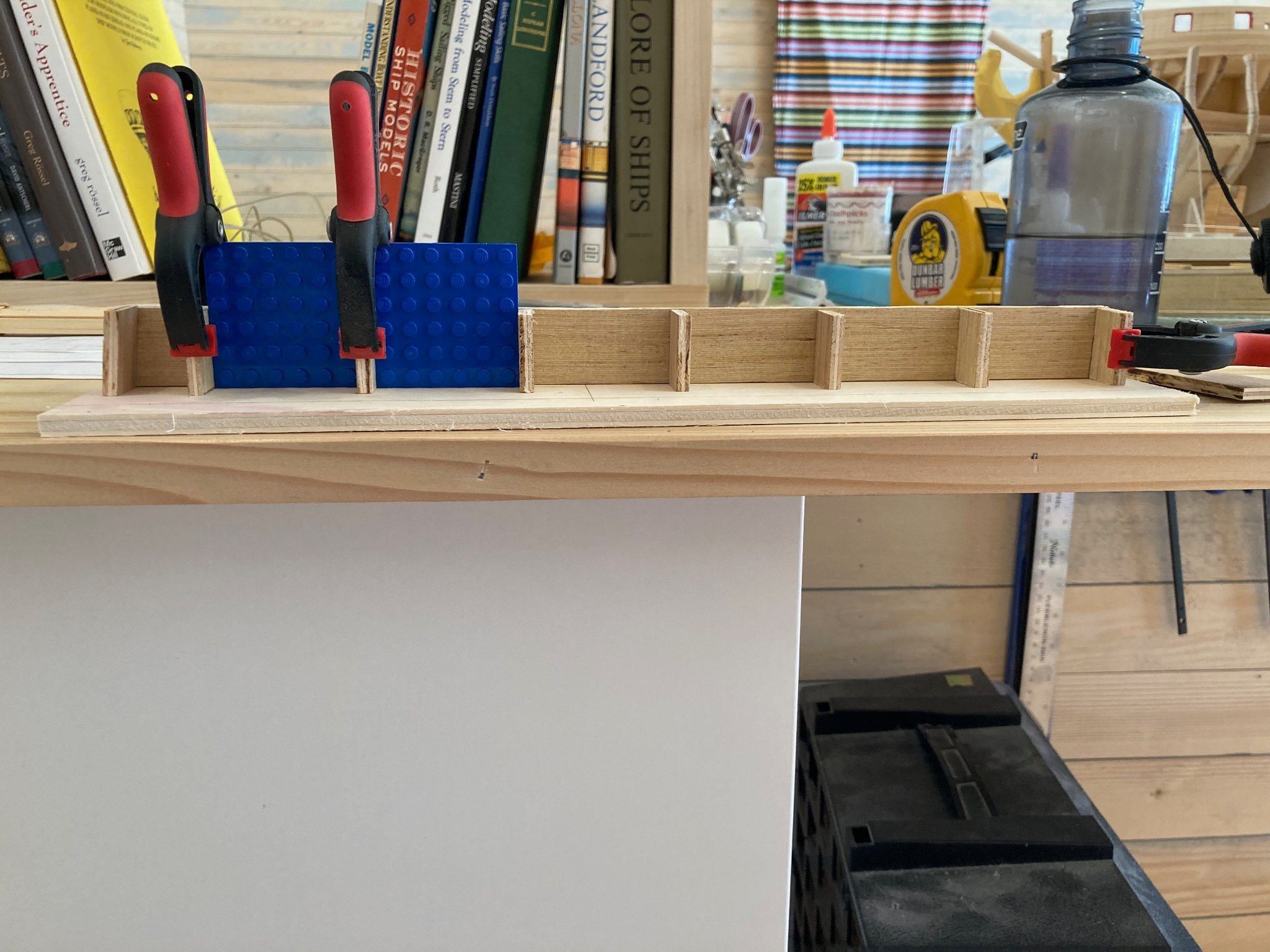
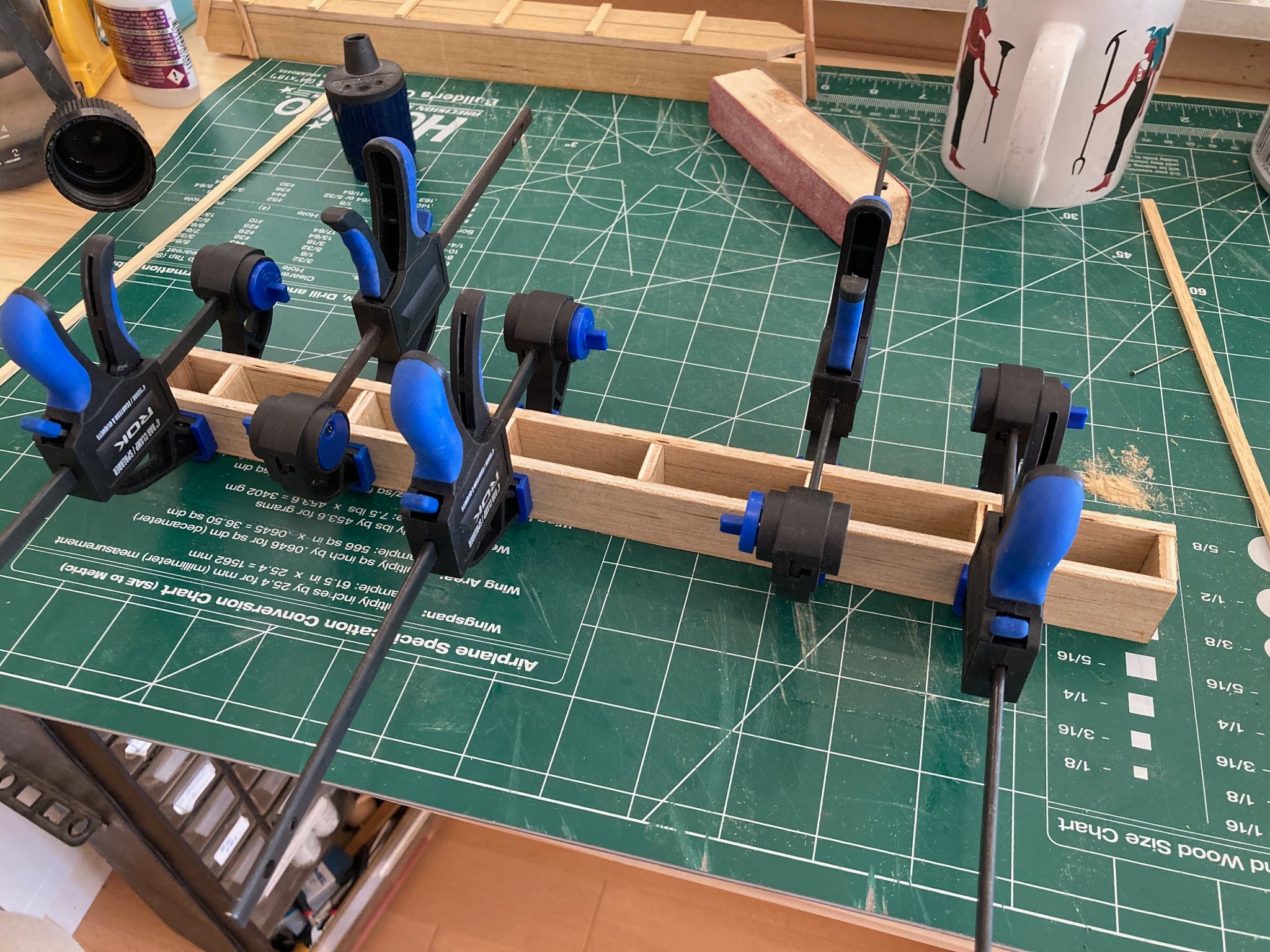
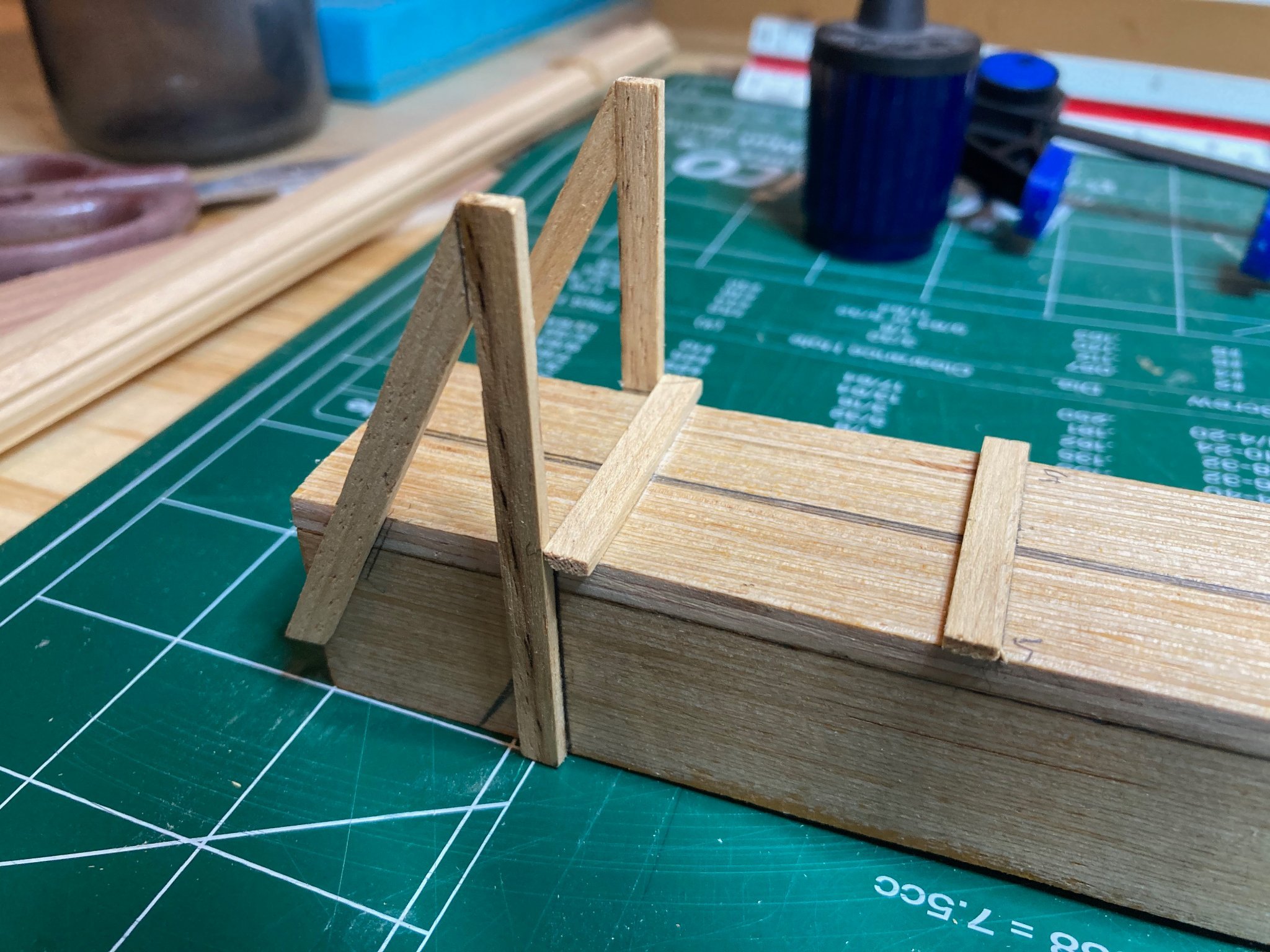
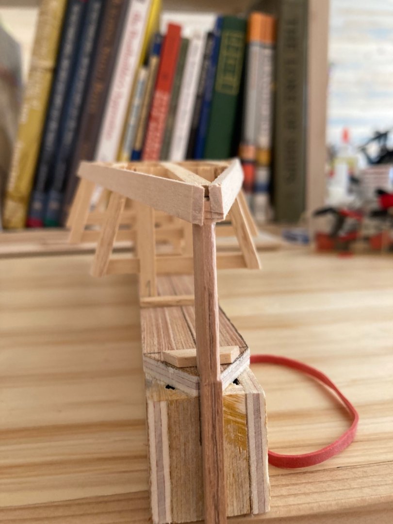
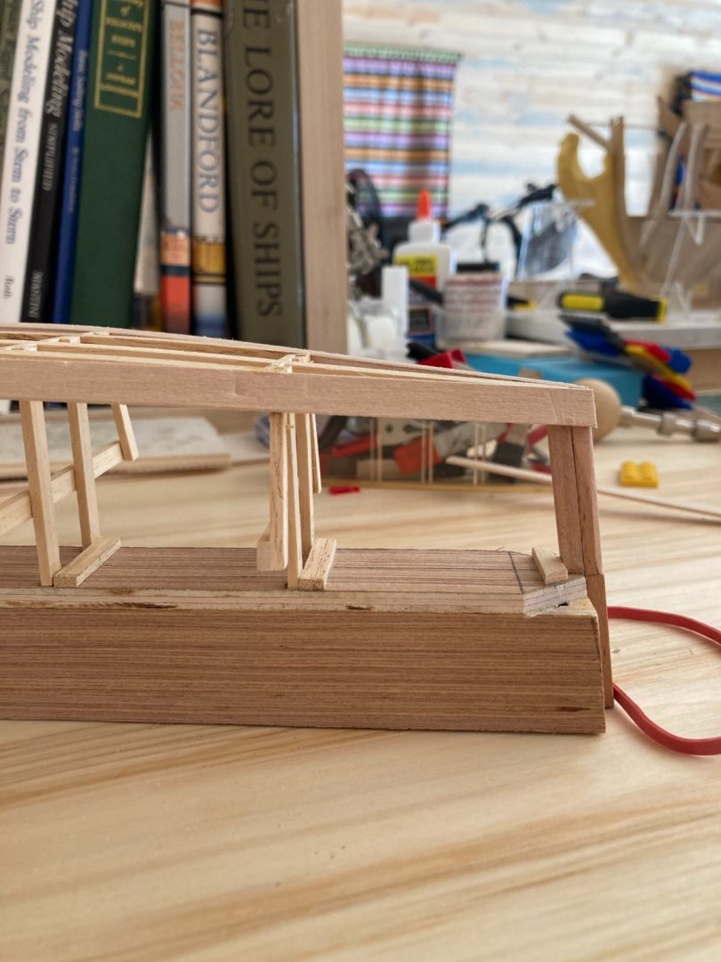
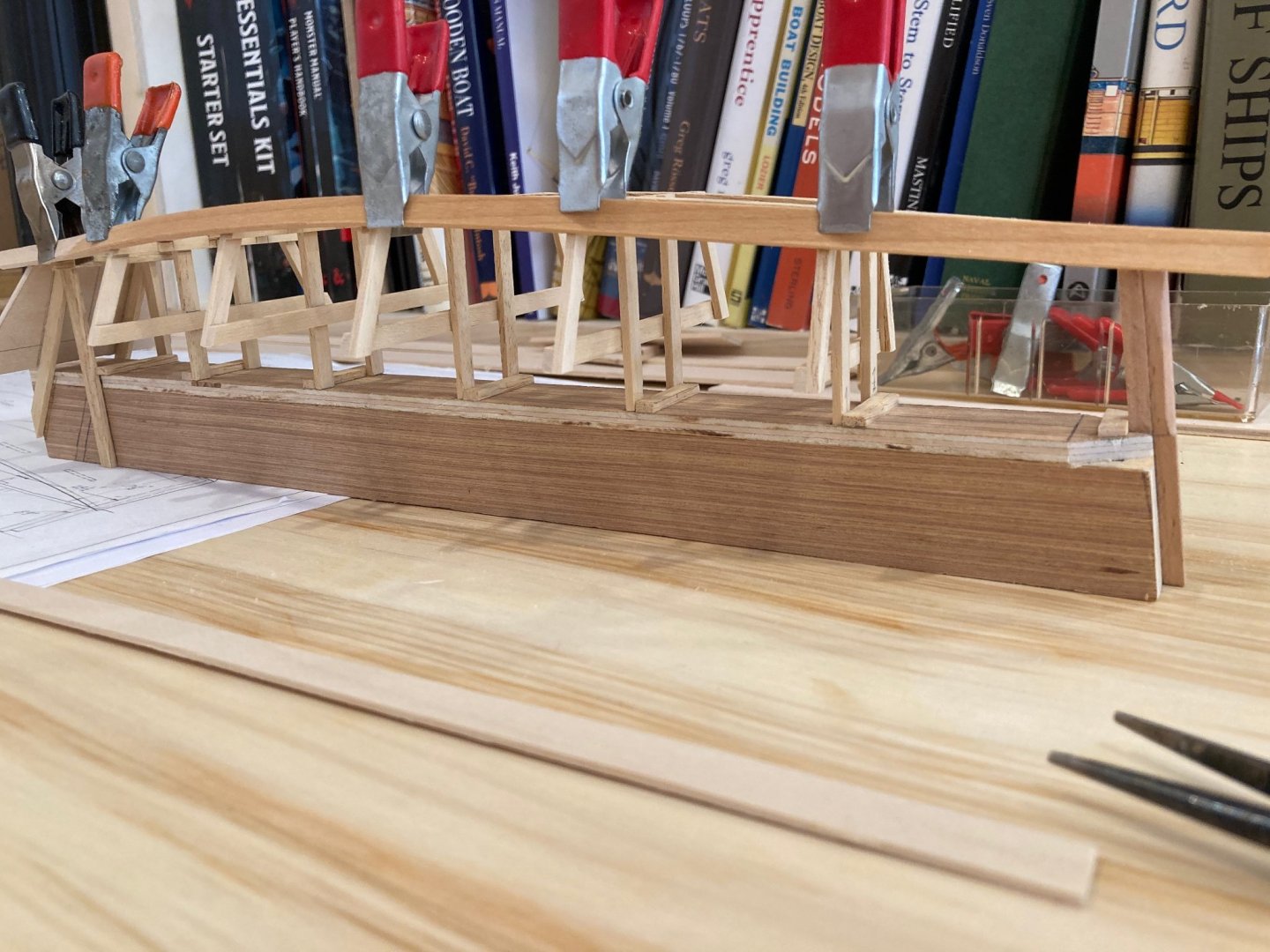
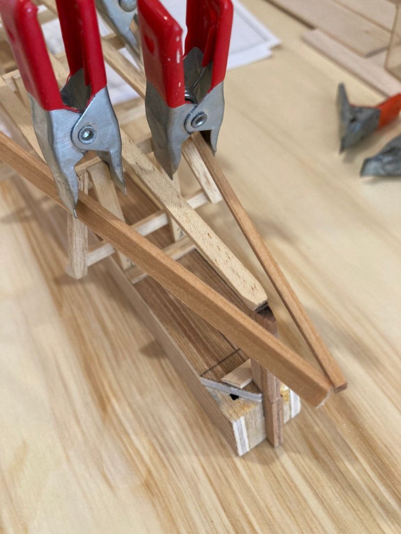
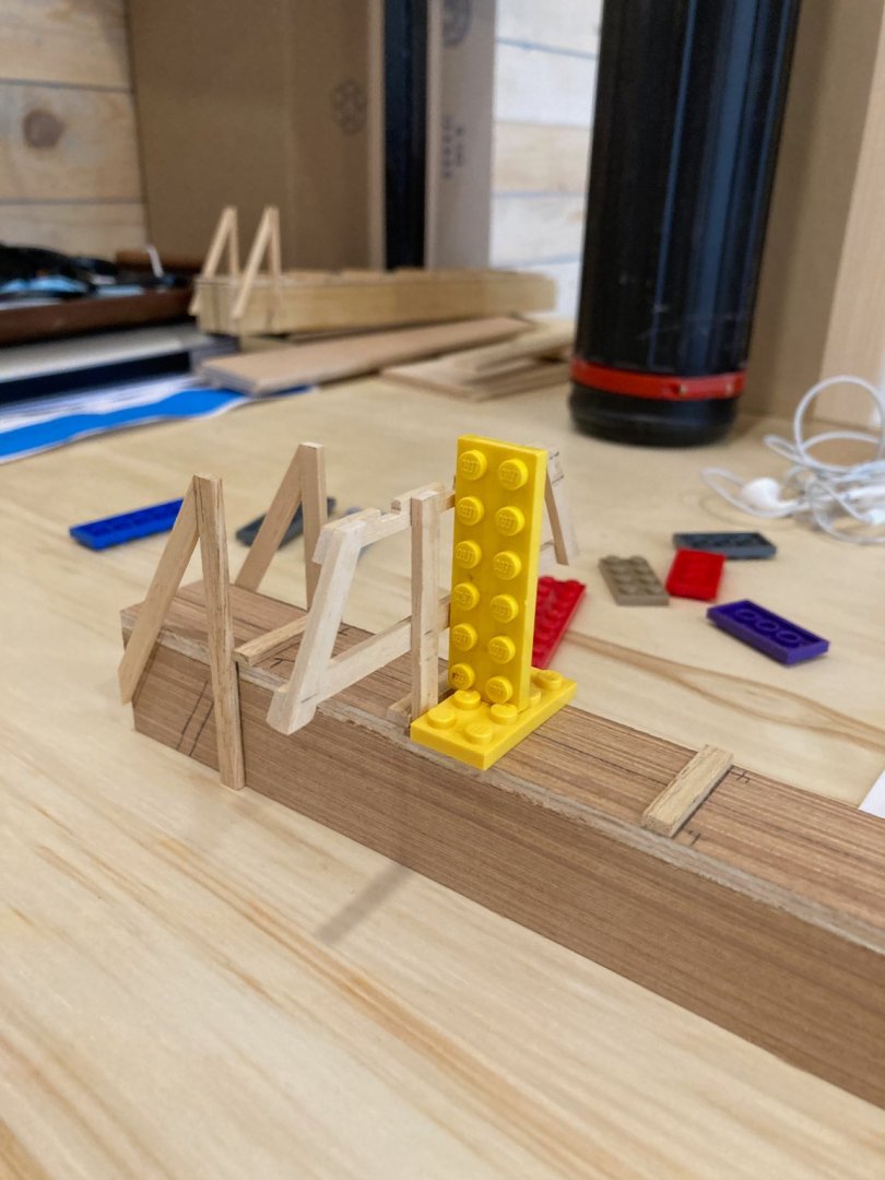
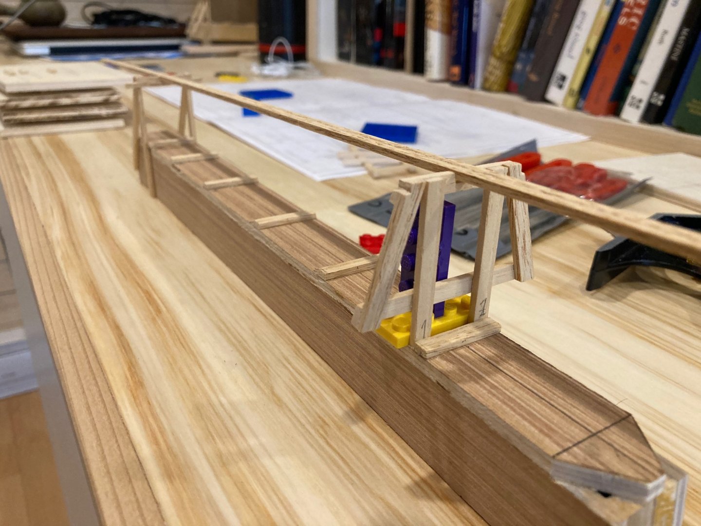
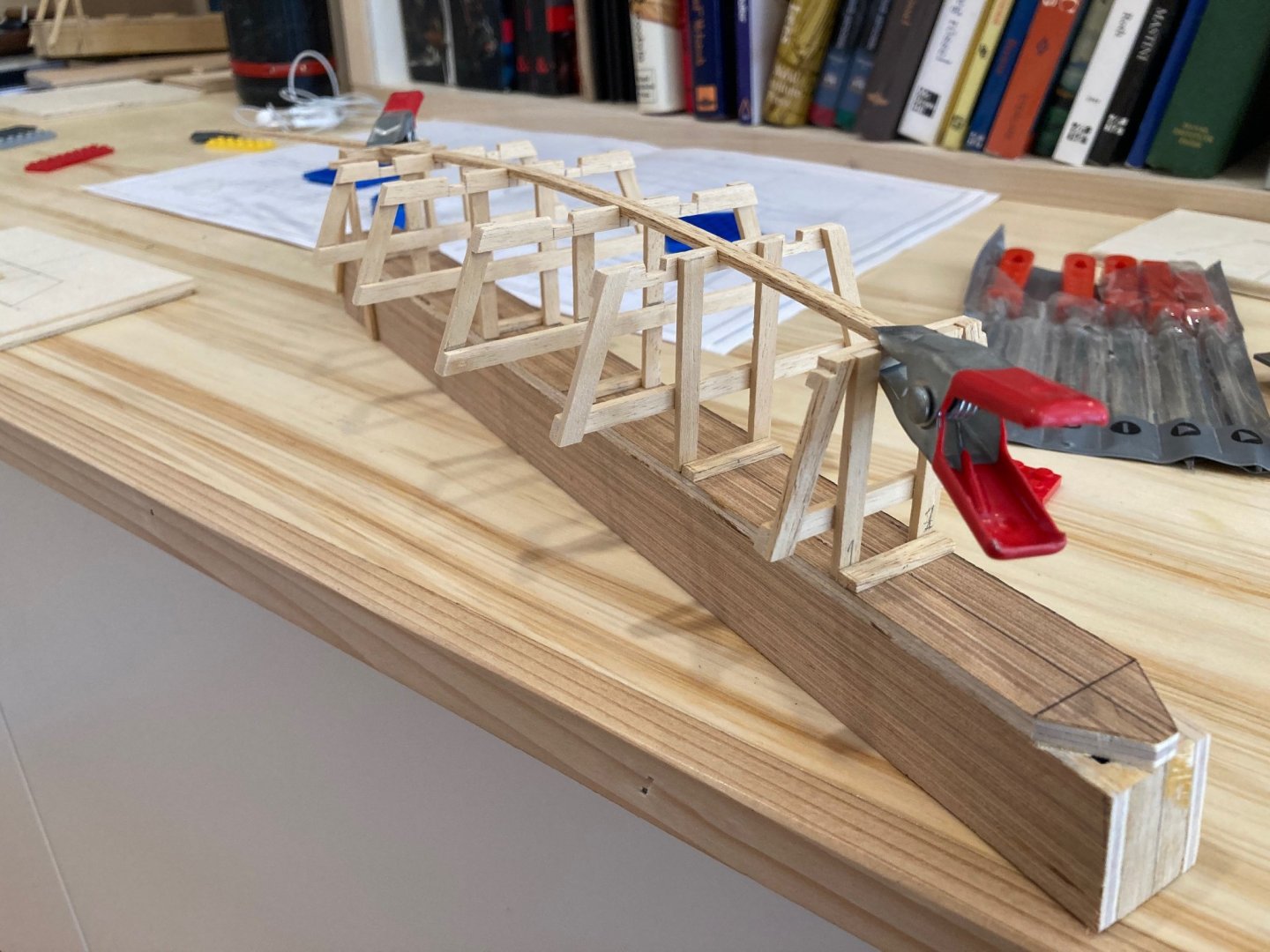
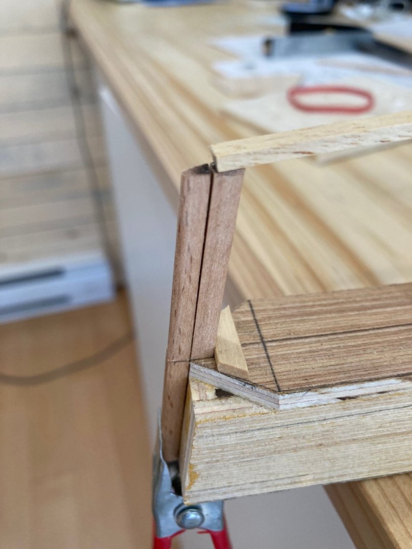
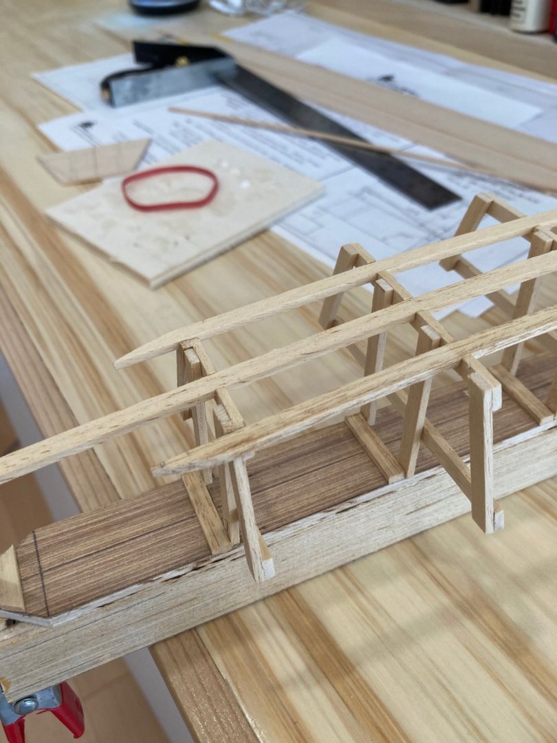
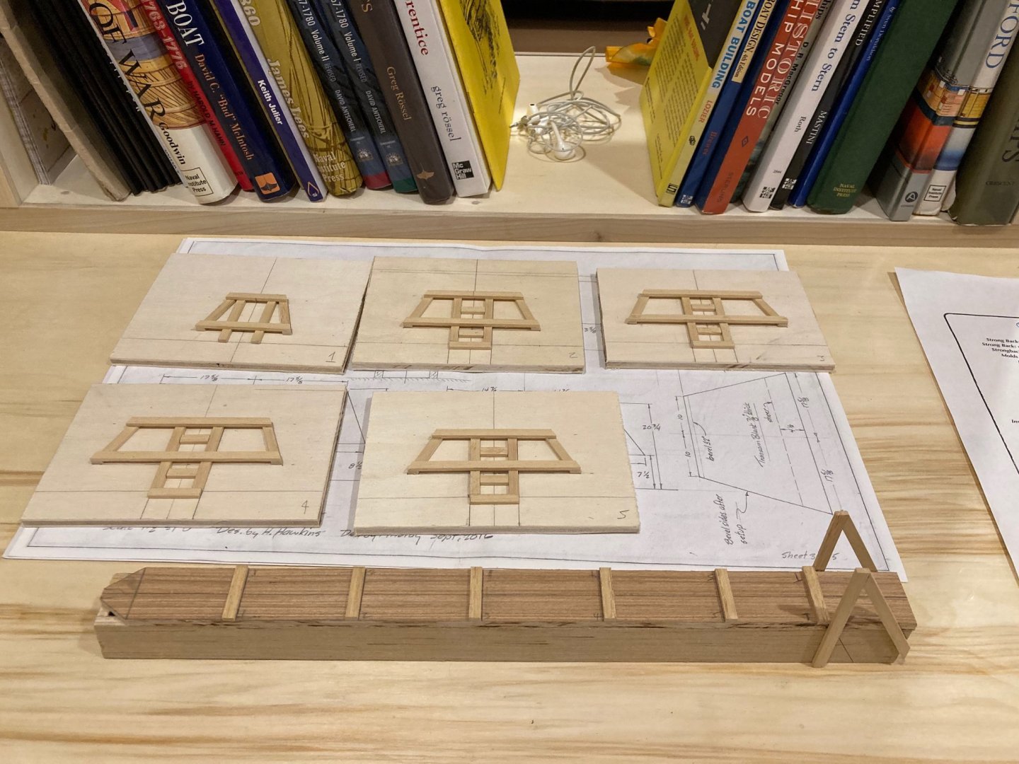
The next stage is to set up the molds on the strongback. This was, again, very finicky but not difficult, and was greatly assisted by the use of a 1/4" x 1/8" ribband along the centre notches between the transom frame and mold 1. The first stage here was to mark the centre line on all the molds using the strongback centre line as reference. For this, I made a small square jig out of a couple of flat 2 x 4 lego pieces angled together - sometimes I think that modellers use more lego than my kids ever have!! These jigs also ensure both squareness across the station lines and in the vertical plane. Anyway, once the centrelines were brought up, and the ribband notches widened around them, I used a 1/4" x 1/8" lime strip to set the molds square and in alignment. The lego brace allowed for a good fit against the station braces, while the ribband provided stability through the mold. I was very gratified to see the nice, sweet curve that the ribband made once the molds were all in place! The final step here was to cut and install the three ribbands in place. These serve a couple of purposes. There's the obvious one of providing structural stability and strength to the framework, but they also serve as reference points for the rubbing strakes that will be added to the bottom of the boat much later. As part of this process, I made a stem bracket to support the centre ribband at the bow, This is a temporary piece, cut to the height of the stem, but serving only to maintain the lines of the boat's bottom. In the photo below, you can also see the inner stem, which is rough tapered through its length from a roughly trapezoidal shape at the upper end to a triangular one at its base. I made the inner stem from a 1/4" x 1/4" strip of beech. The port and starboard ribbands also had to be trimmed back and faired to the run of the planking, as you'll see in one of the images below. Photos documenting these steps follow. Enjoy! hamilton


-
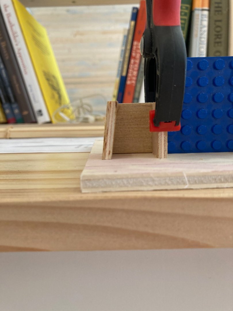
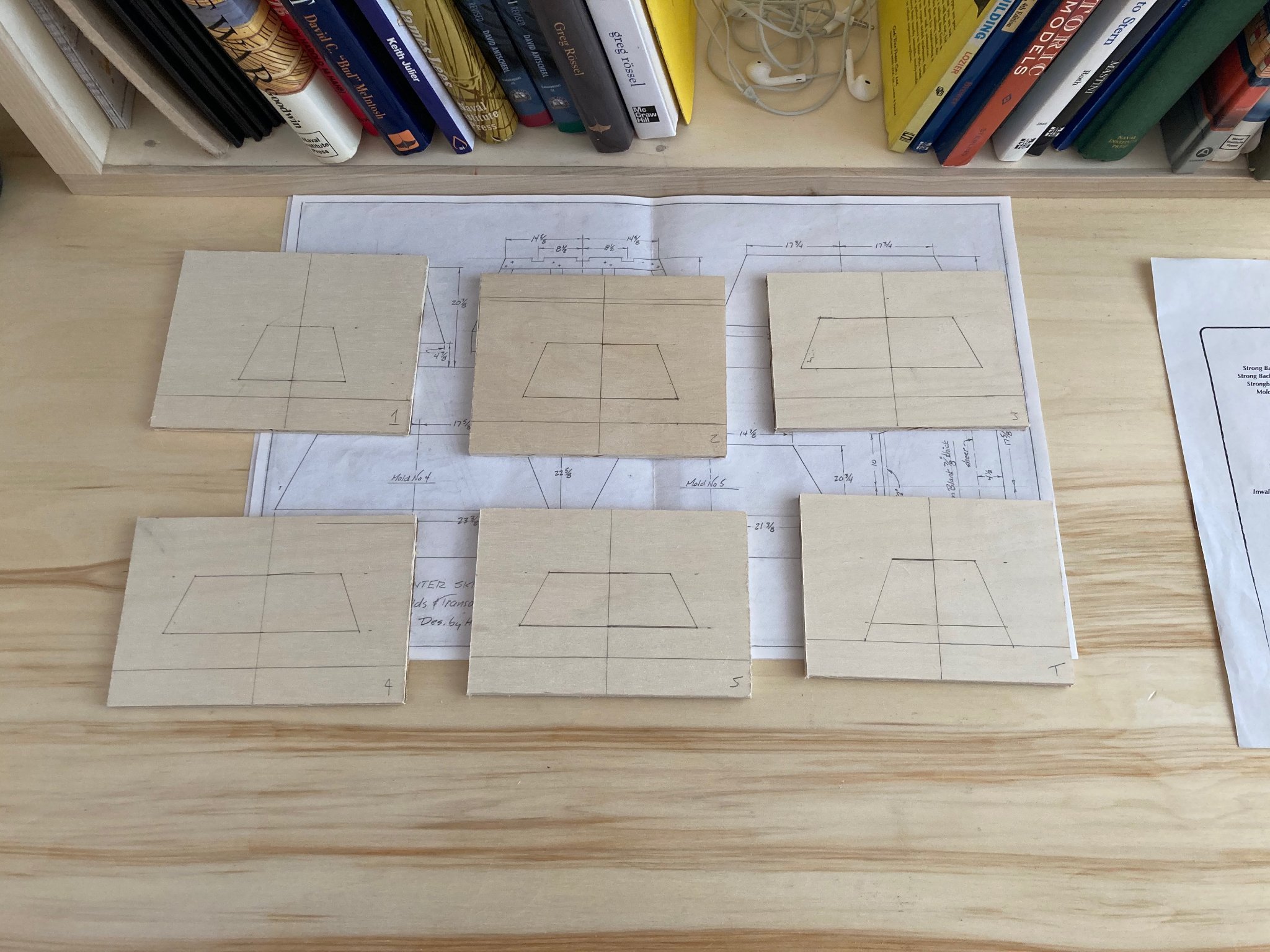
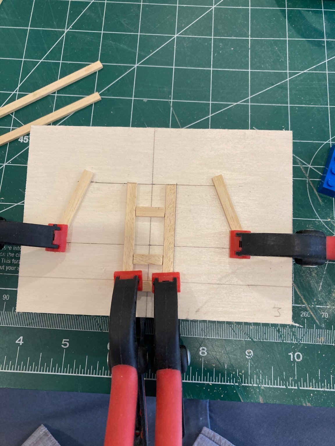
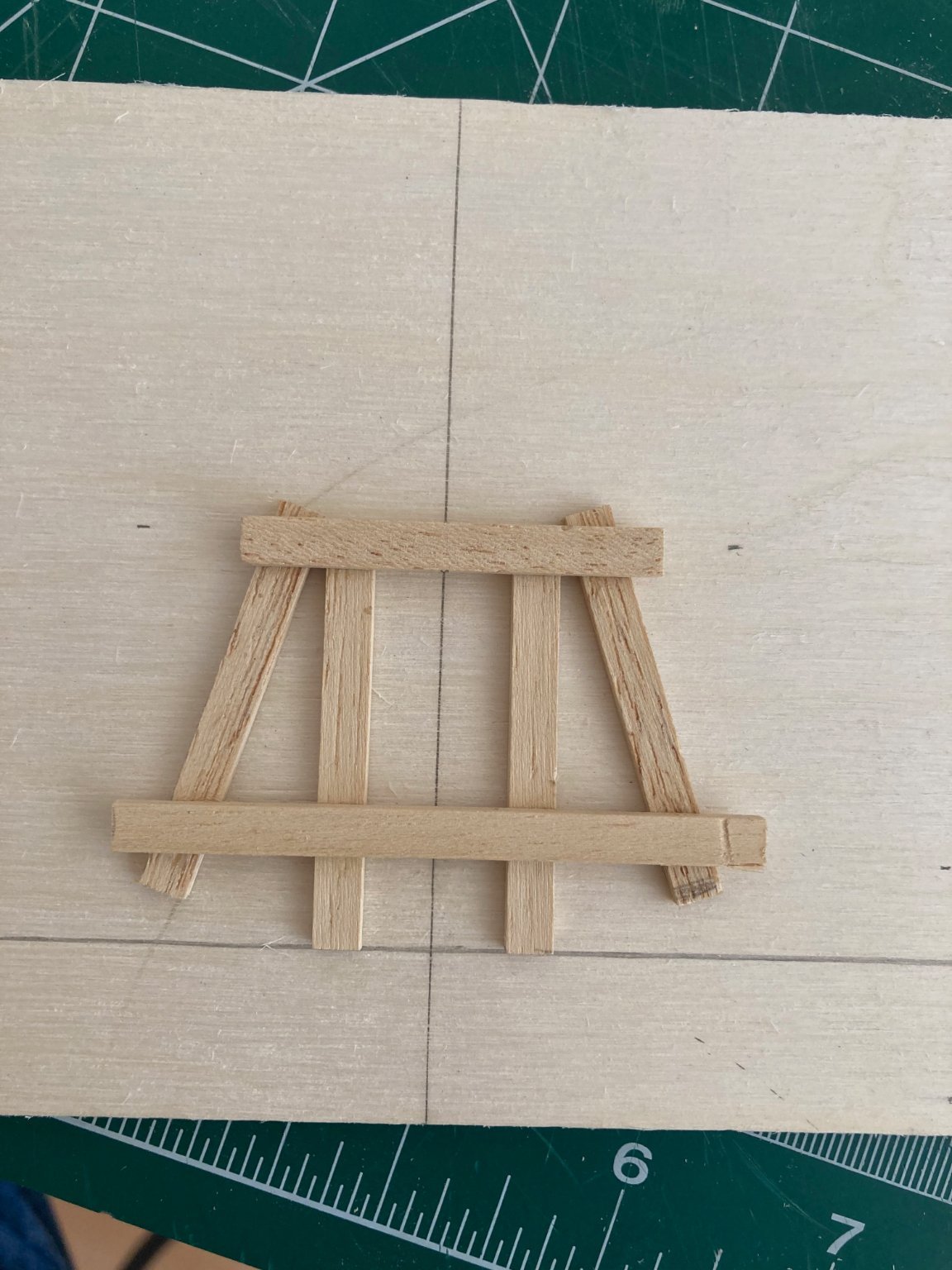
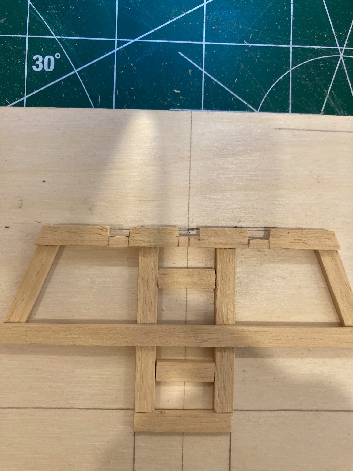
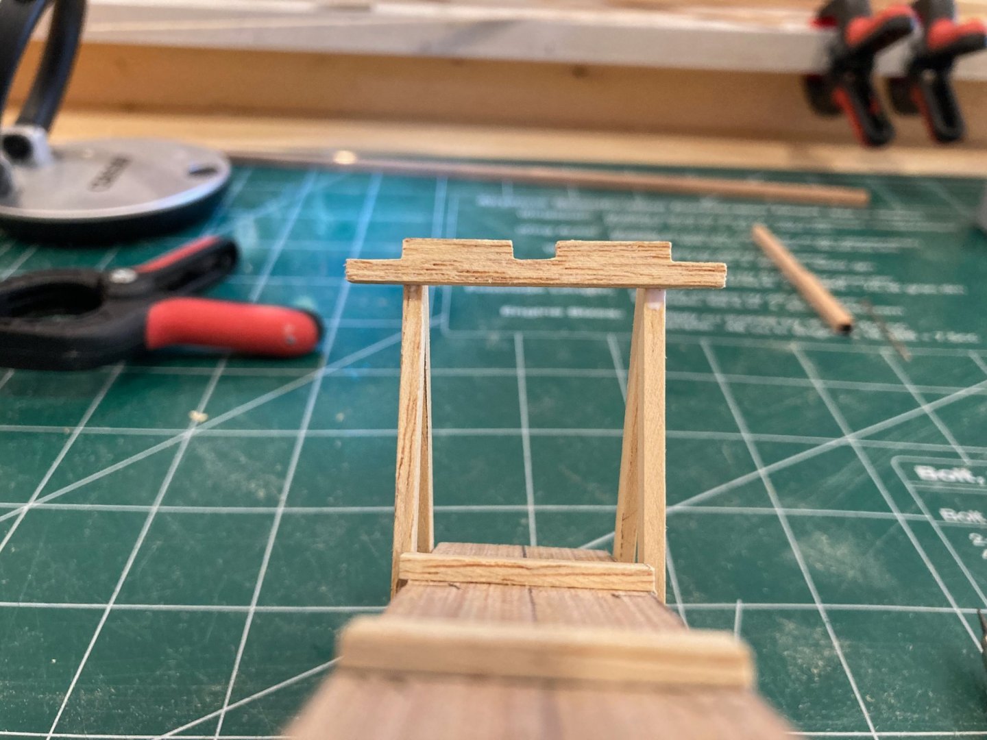
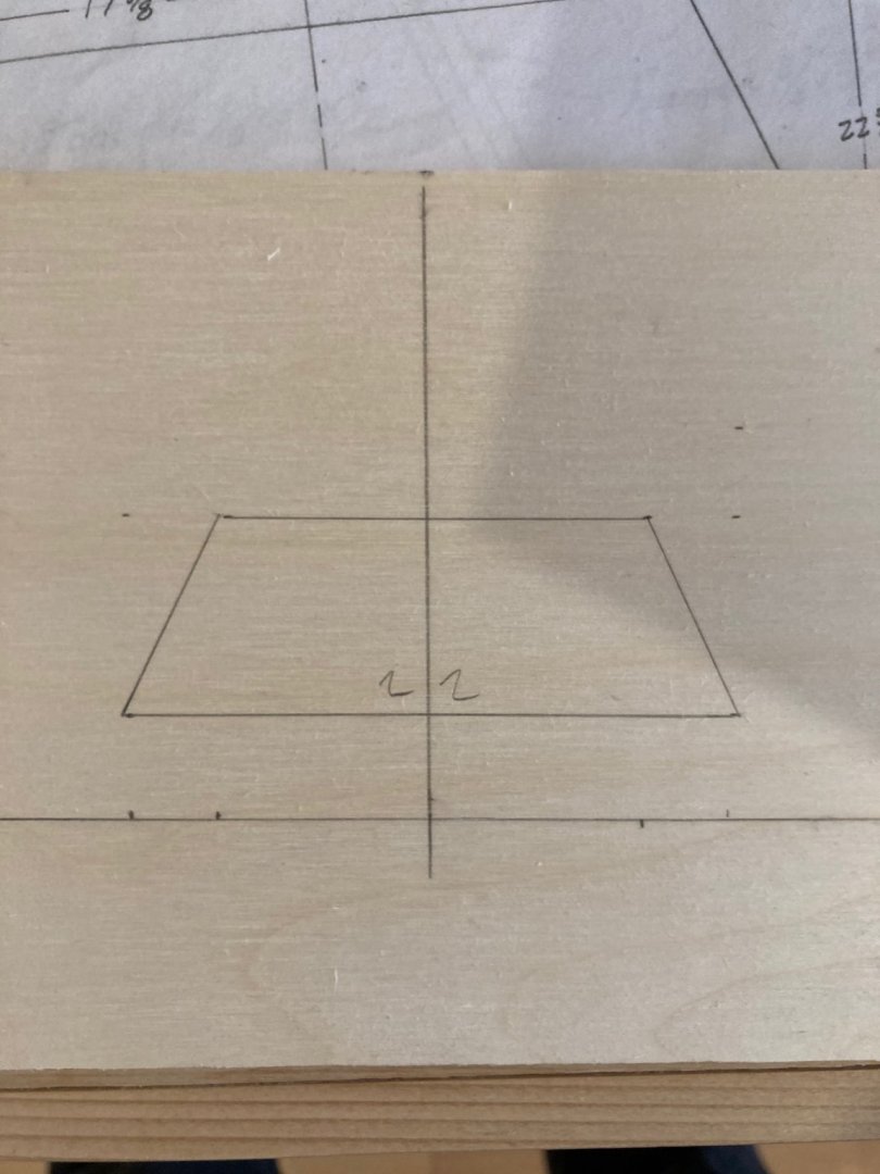
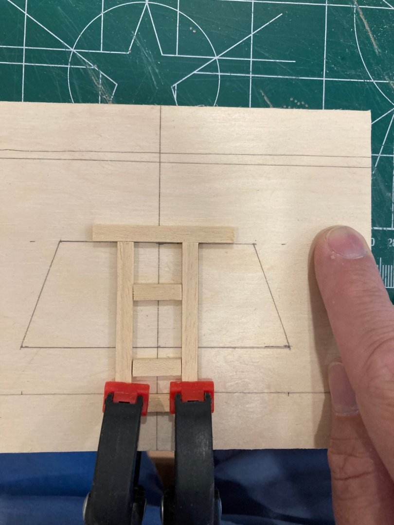
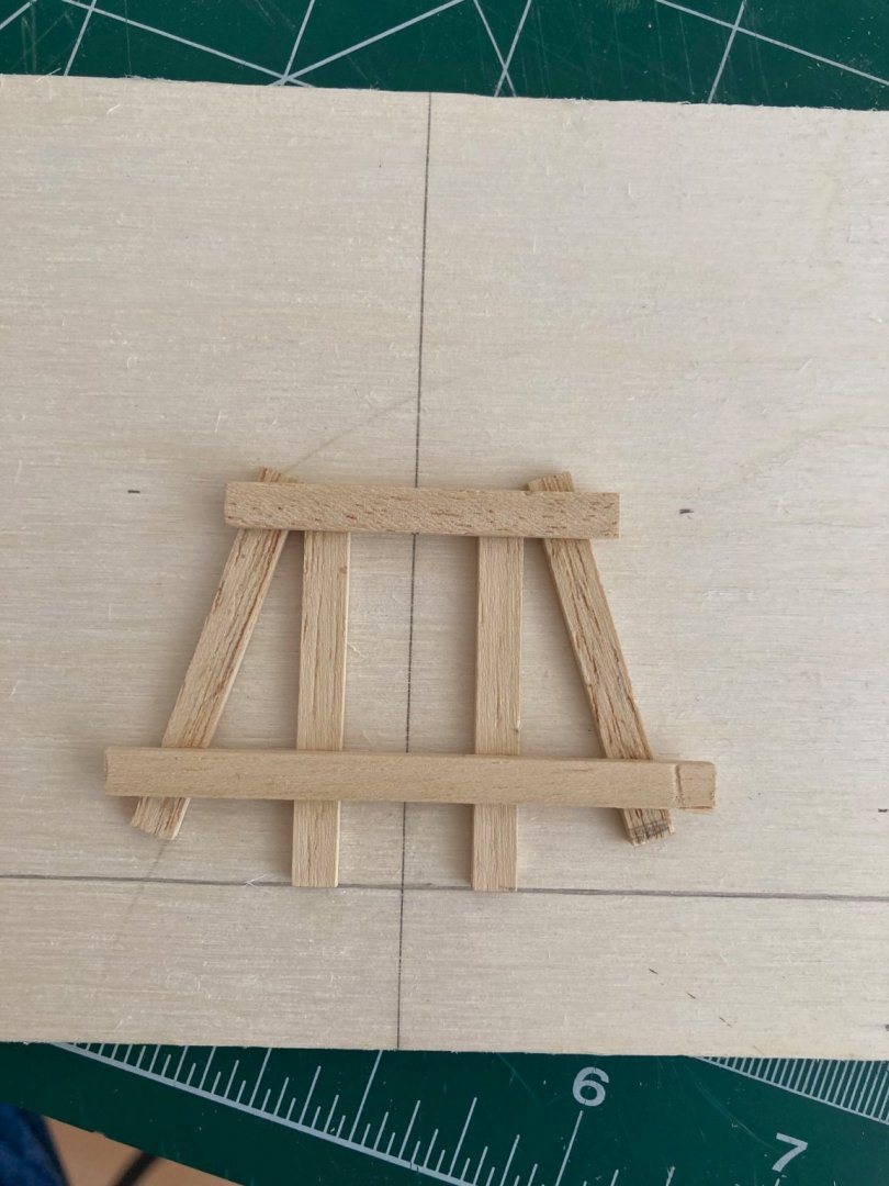
Hello again: Following the construction of the strongback it was time to make the molds. There are 5 molds plus the transom. These were made using the same 1/8" x 1/4" lime that was used for the transom bracket and the braces on the station lines. Taking off the measurements from the plans was finicky (especially where there were fractional measures in the /8 range) but not too difficult - keeping a very sharp pencil and using a magnifying lens helped considerably. I did have to make a few of the molds a couple of times as I made some calculation errors the first go around, but in the end, the results were good - symmetrical, solid and accurate to the offsets given on the plans. For each of the molds, I first drew a baseline and centre line on a small piece of 1/4" plywood. I then took the offsets from the drawing to make a basic outline of the mold (to the inside of the planking). I then fixed a 1/4" x 1/8" lime strip along the baseline to act as an anchor piece for the construction of the mold. Two more pieces were cut to act as braces for the verticals to insure that they retained a consistent 12" run from their outside edges. The bracing strip that you see in one of the images below is not fixed, but is used to ensure symmetry in the verticals and (later) to help brace the whole mold while it's being glued up. The verticals and the angled sides of the mold both lie on the control edge, so the side pieces were clamped down in position as a next step, with clamps being added at the base of the verticals for stability and accuracy in setting the horizontal pieces. All these pieces (with the exception of the verticals) were cut overlength and then shaved down on the disc sander - which I am increasingly finding to be one of the most useful and indispensable tools in the shop. The final step in mold construction was to cut three notches in the smaller crosspiece to allow for the ribbands which serve as structural reinforcements later in the process. A crossbar with similar notches was also made for the transom support frame. These also serve the purpose of ensuring the correct alignment of the molds once they are set up on the strongback. Here are some images documenting the process. Enjoy! hamilton


-
Hello all. The first stage in the construction of the OC Skiff is building a strongback on which the molds will rest. I built this from some 1/4" plywood that our contractors left over from the renovation of our garage, which is where my workshop is located. The strongback's dimensions are 12" x 14', with a number of 9" bracing pieces on the interior for strength. The forward end of the strongback is raked at 83 degrees to (later) support the inner stem. A centre line and station lines were marked on the strongback, including a reference line where the verticals of the transom support frame will go. Several 1/8" lime strips were used as support braces at each of the reference lines to add stability to the molds, once they are attached. The forward end of strongback cap also had to be cut to a 1/4" point at the end to accommodate the sheer planking where it connects to the inner stem. Finally, the transom support frame (raked at 60 degrees) was added. Here are some pictures to document the process...somehow I failed to get an overall shot of the finished strongback.....Enjoy! hamilton