Jobbie
-
Posts
220 -
Joined
-
Last visited
Content Type
Profiles
Forums
Gallery
Events
Everything posted by Jobbie
-
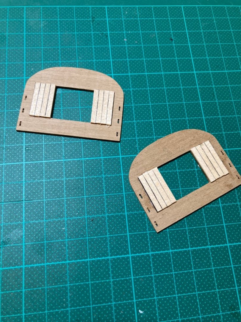
 I did. Thanks. After all that, I find I’m not too happy with the look of the tops. They’re a different wood strip to the deck and look more bleached. I don’t have any deck planks left over to re-lay the tops. I’m thinking about painting over the planks with black to match the kit’s box-top photo. Thoughts?
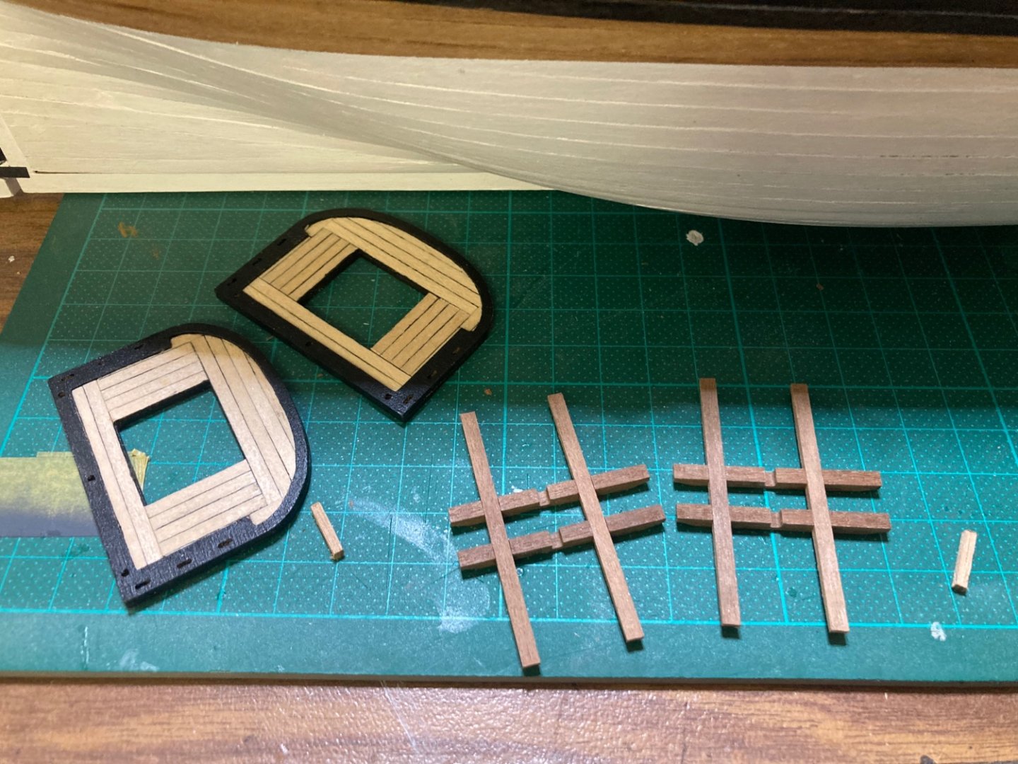

-
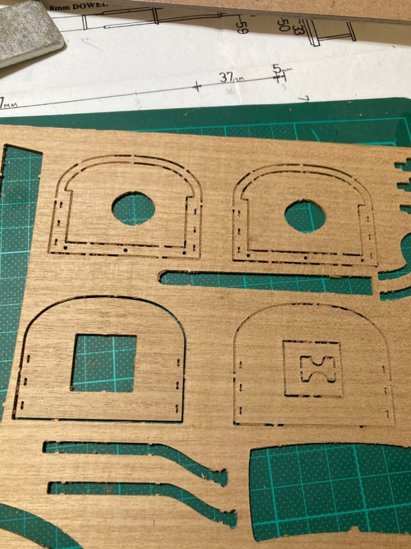
Tops. The image on the box-top shows the tops painted black. They look great but I want to plank them. I have 3mm x 1mm basswood leftover from another kit, so I’m simply laminating the pre-cut tops. My hope is to have their edge-boards painted black and placed flush around my planks. I’ll paint the undersides black.
-
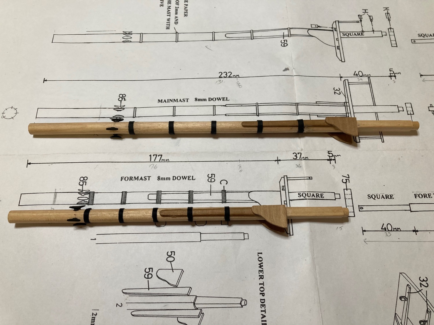
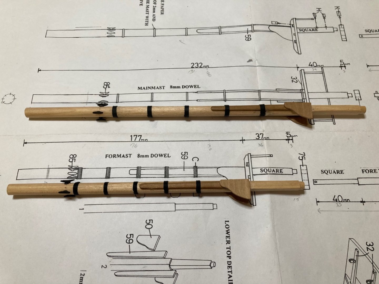
Wooldings. There’s rope wooldings on the foremast and iron hoops on the mainmast. According to Longridge’s “Anatomy of Nelson’s Ships” book, the British Admiralty changed from rope wooldings to iron hoops a few years before Trafalgar- 1805. HM Brig Supply was part of the First Fleet- 1788. That tracks. 0.5mm black hemp as rope. Black cartridge paper as iron.
-
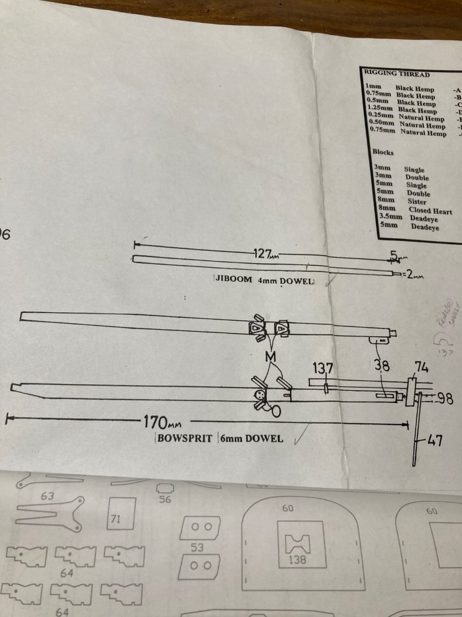
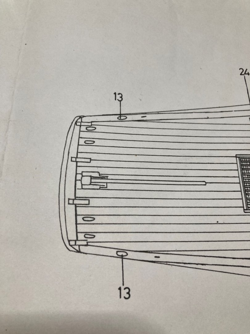
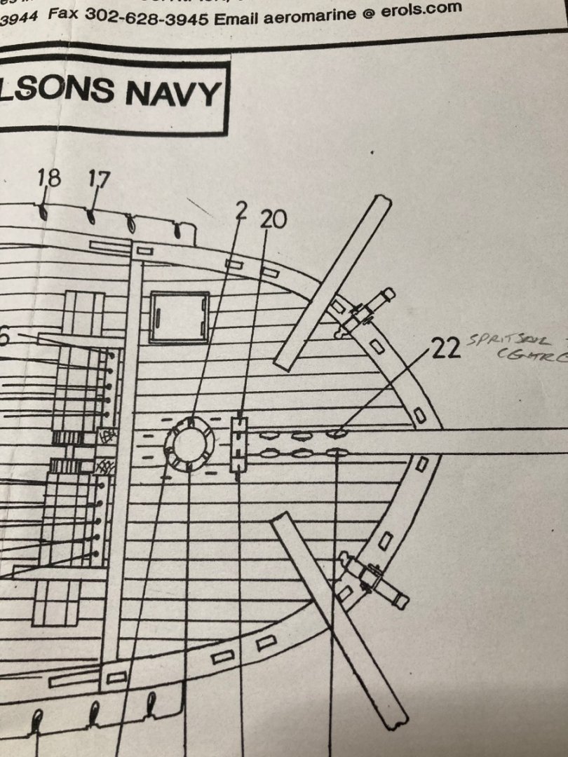
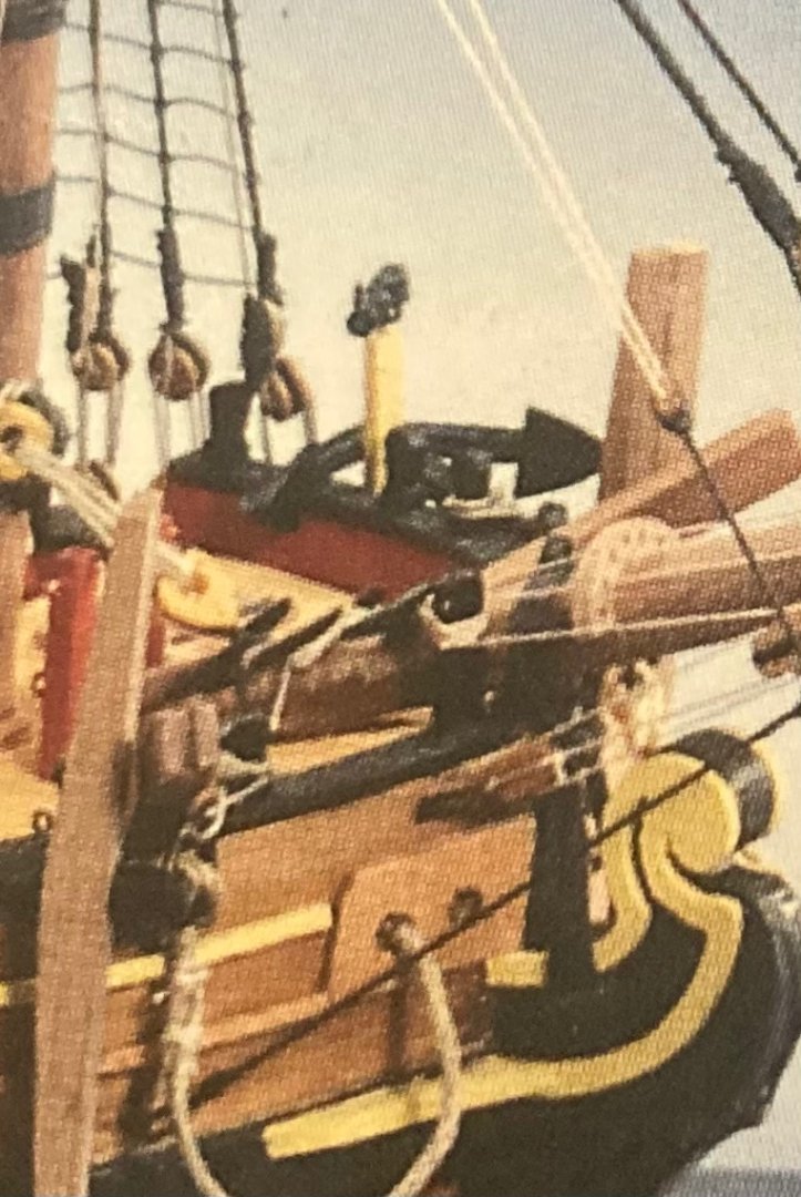
This brings up the third bowsprit error. There aren’t enough cleats (part 85 - casting - qty 25) in the kit to complete the bowsprit as shown on sheet 3. The cleats are placed as follows (Sheet 3 of 6- (Shrouds & ratlines.) - Top view. From stern to bow; 4x cleats across the rear edge of the ship, 2x on the bulwark capping either side of the tiller, 7x around the base of the mainmast, 2x inside the bulwarks either side of the main hatch, 2x inside the bulwarks either side of the forward hatch, 7x around the base of the foremast. 24 total - 25 supplied. On the same plan, and indeed on the photos on the box-top, there’s 6x cleats shown on the aft end of the bowsprit. I’m 5x short if this is correct. I’ve emailed JoTiKa / Caldercraft / Shipwrightshop.com (whatever they’re calling themselves this week) with a view of correcting these errors in the plans for future customers. I’m not holding my breath. Initially, I was just going to cut down on the number of cleats on the masts and move some to the bowsprit, but I don’t like how they look now. I’ll hopefully buy new cleats from Float-A-Boat, the Australian supplier, once they reopen in February. Happy to pay for them myself.
-
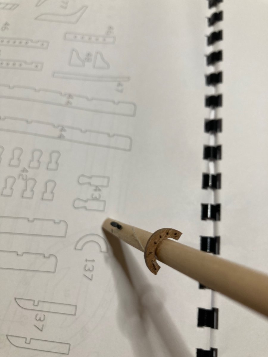
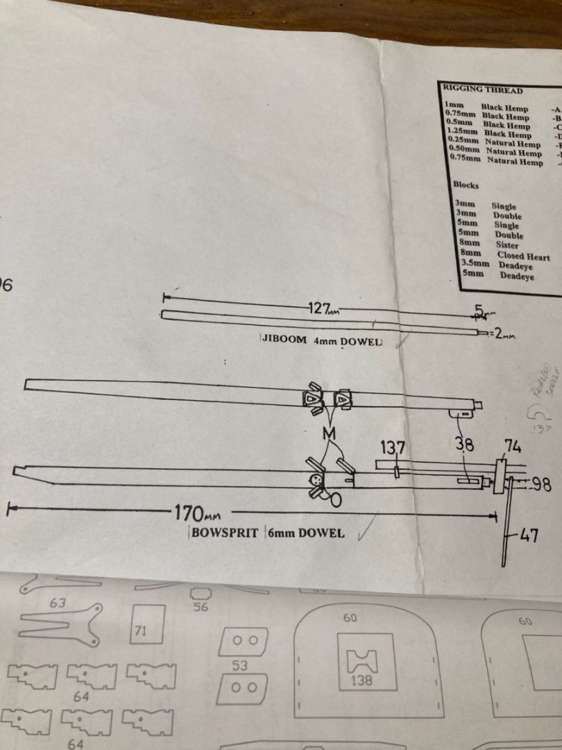
This leads to the second error. Part 137 (fairlead saddle) isn’t shown on any plan or written in the instructions. To find out where it’s placed, I had to take a photo of the bowsprit on the boxtop and zoom in a great deal. The fairlead saddle’s placed just forward of the bowsprit’s gammoning to separate the spiritsail boom’s running rigging (#3 x2 & #20 x1) before they’re tied to cleats (Sheet 3 of 6- (Shrouds & ratlines.) - Top view. however. Maybe the fairlead saddle’s a deliberate omission by Caldercraft. The saddle has an 8mm internal diameter and the bowsprit’s 6mm dowel.

-
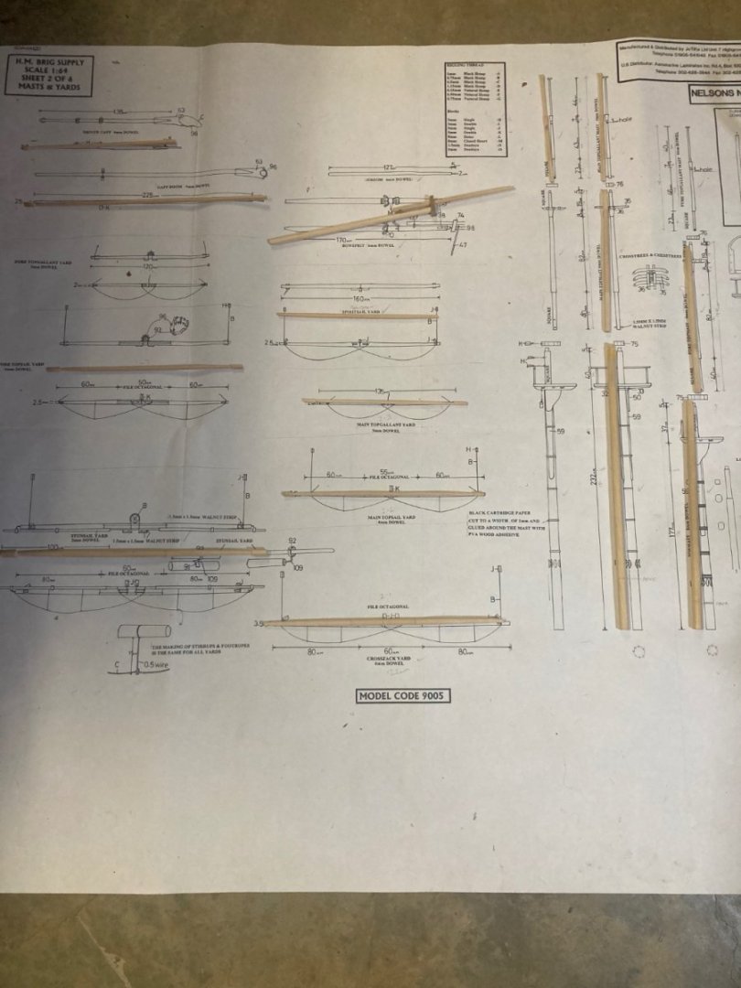
I’ve found a couple of errors in the kit in regards to the bowsprit. Sheet 2 of 6- (Mast and yards); Whereas the build instructions state “Glue on the jib-boom saddle (138) to the bow-sprit as shown on the plan”, the plan itself refers to part 137. Part 138 is the correct part. It’s listed as 138 (Jib-boom support saddle) in the parts list and is pre-cut, located inside the Lubber’s Hole on the 1.5mm walnut sheet.
-
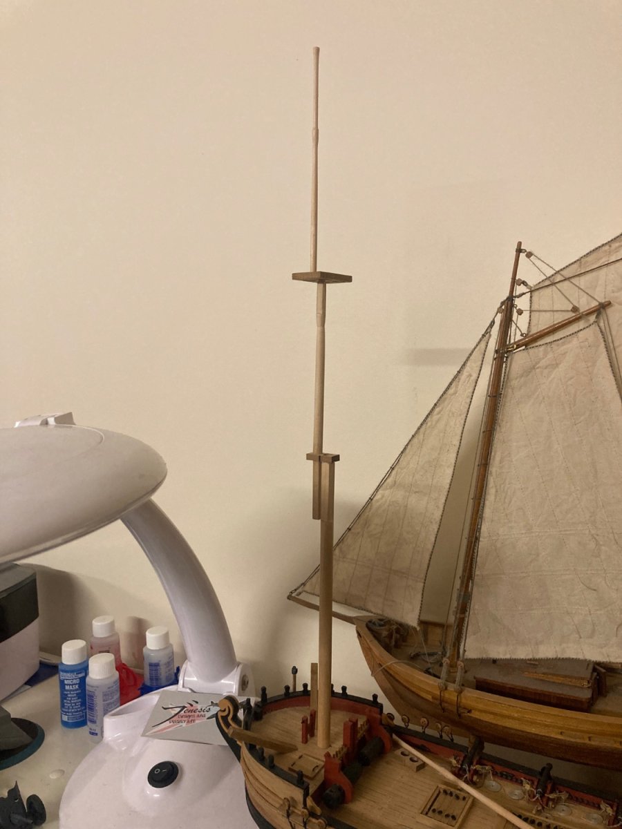
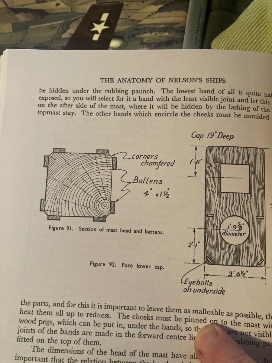
If someone asked me if C Nepean Longridge’s book ‘Anatomy Of Nelson’s Ships’ helped me in getting the trestle-trees correctly horizontal on top of the mast’s cheeks, I can truthfully answer yes.
-
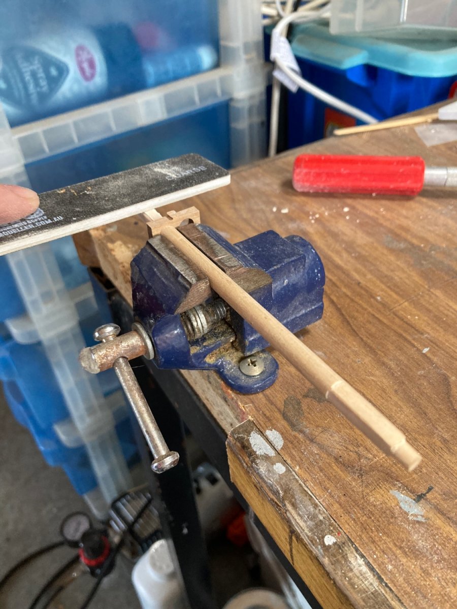
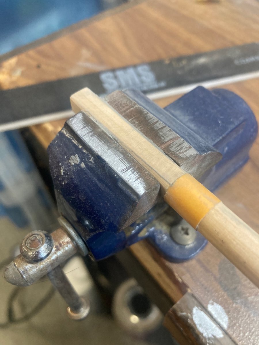
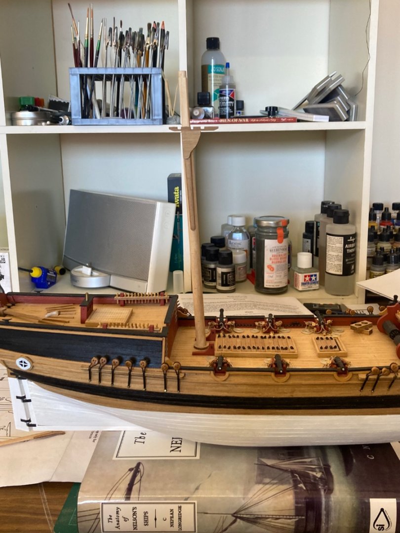
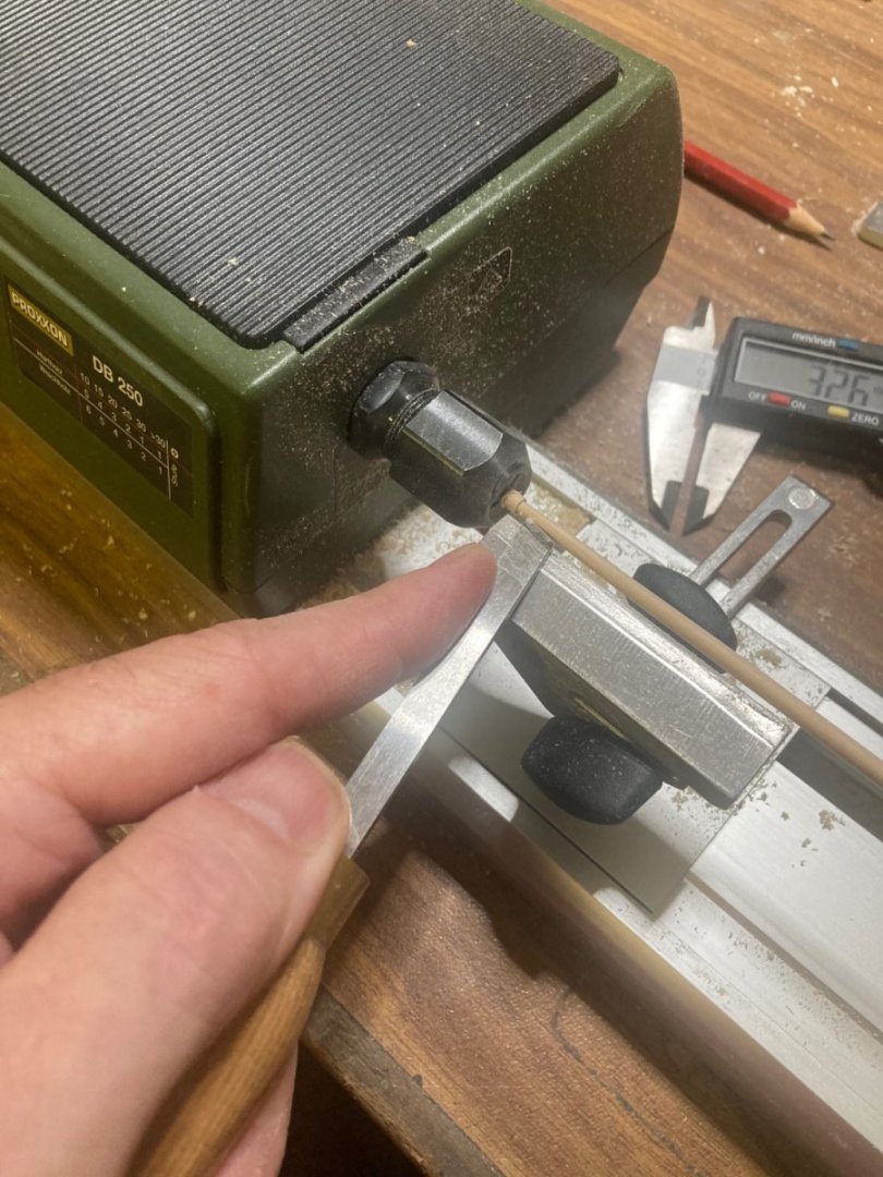
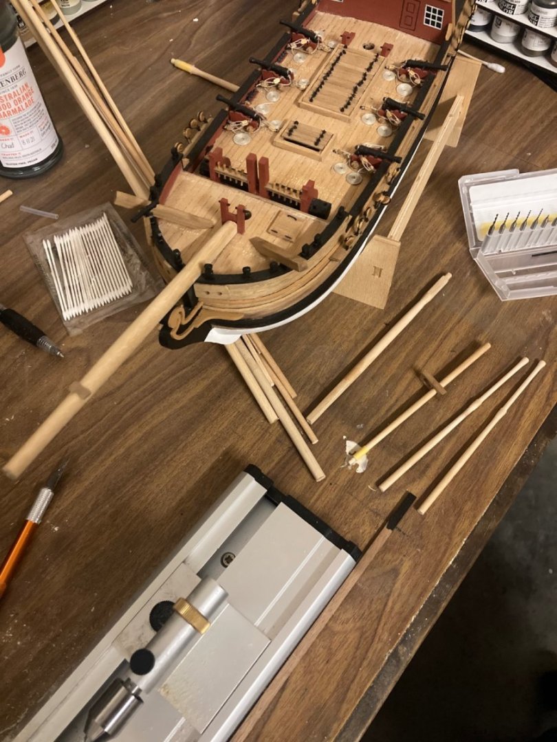
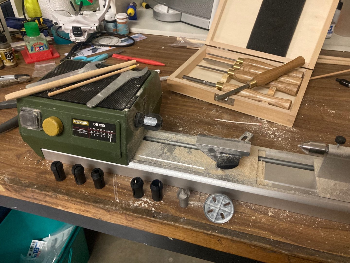
The lathe is making short work of the yards. Sawdust everywhere!
-
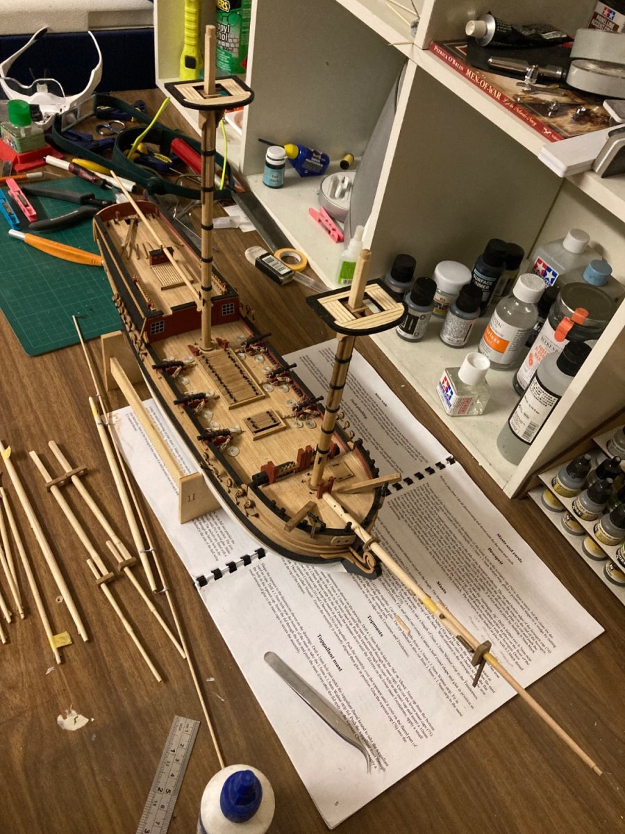
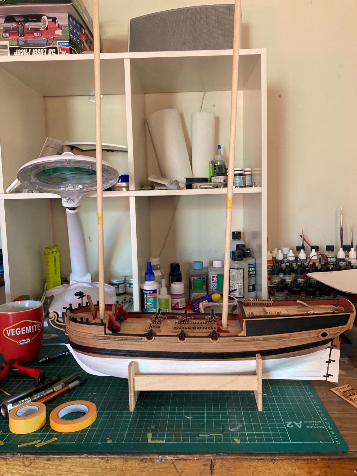
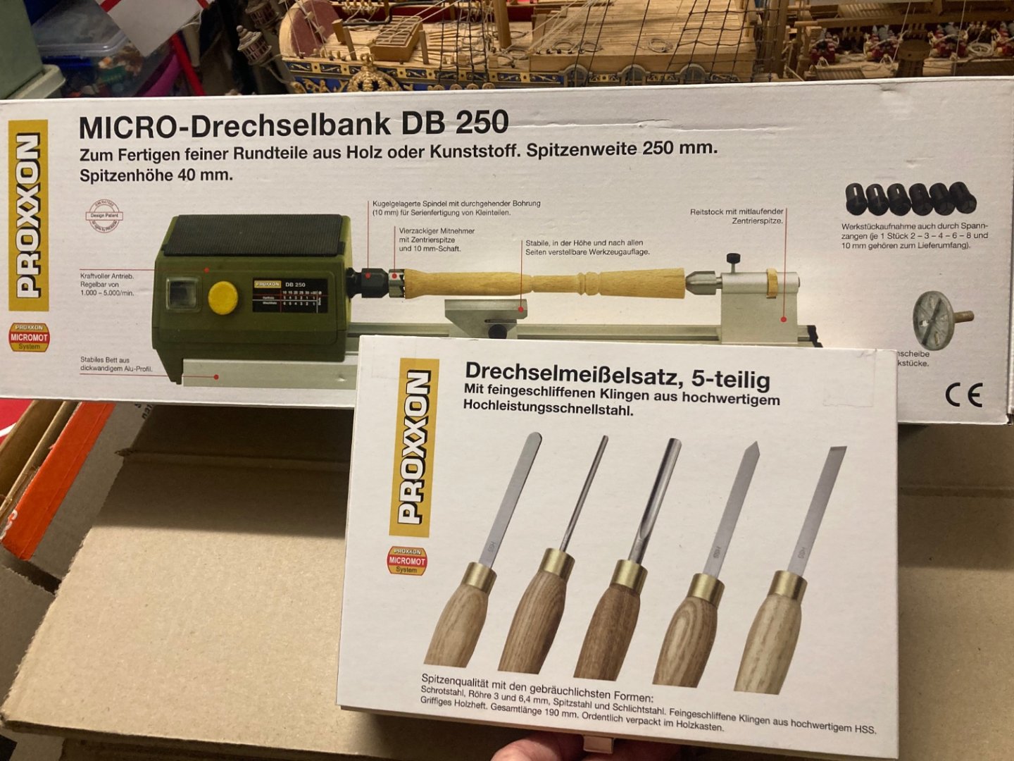
In the last month, my 27 year career in the Royal Australian Air Force came crashing to a halt. I’ve been medically discharged as a result of a spinal condition. As a retirement gift, my darling wife graciously allowed the release of funds to purchase a Proxxon DB 250 wood lathe and turning chisels. Whilst I wouldn’t class them as essential, these are certainly making the turning and tapering of masts and yards for the Supply easier. And it’s really a joy to use. The HMS Supply once again replaces plastic kits on my bench.

-
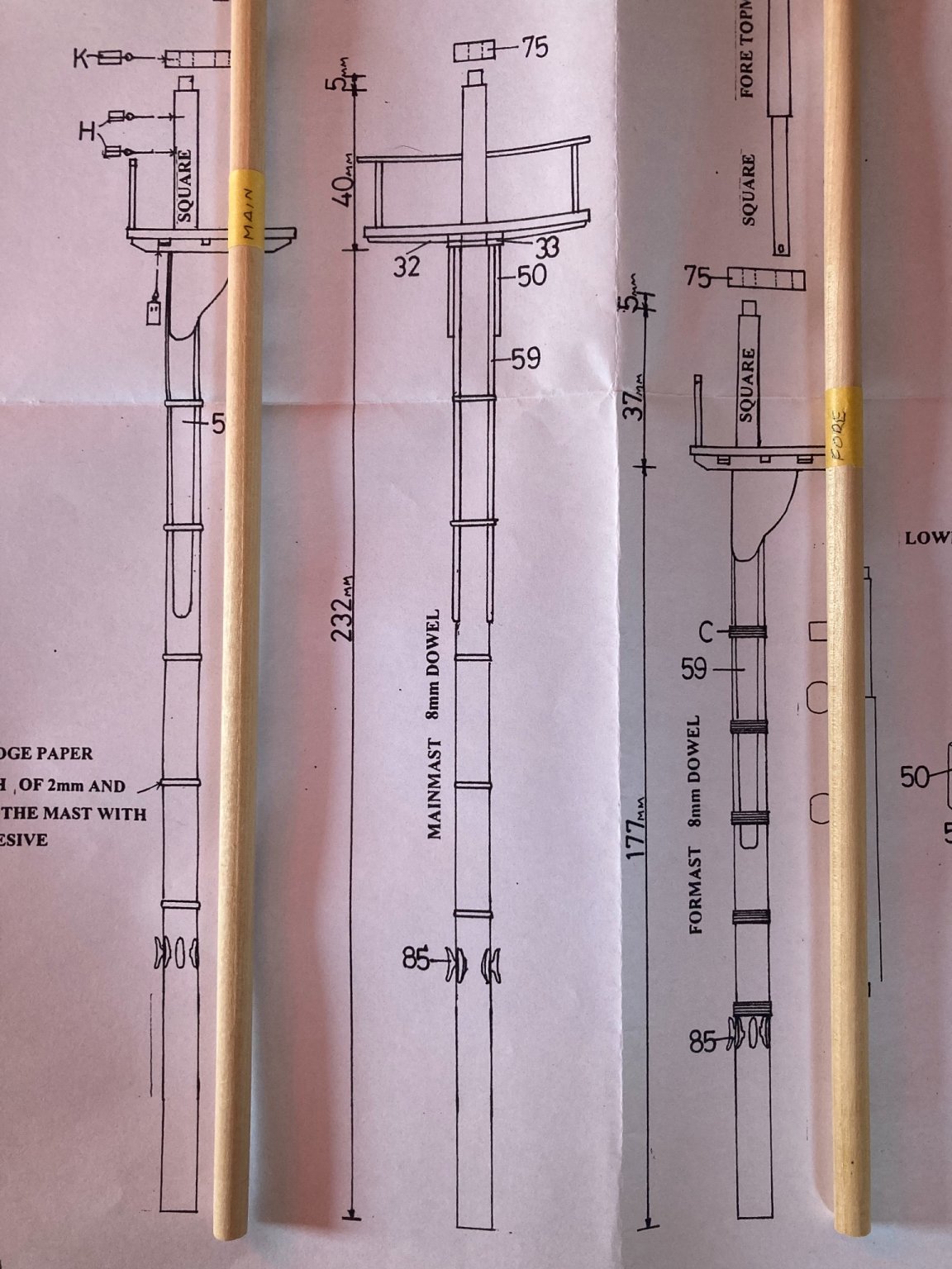
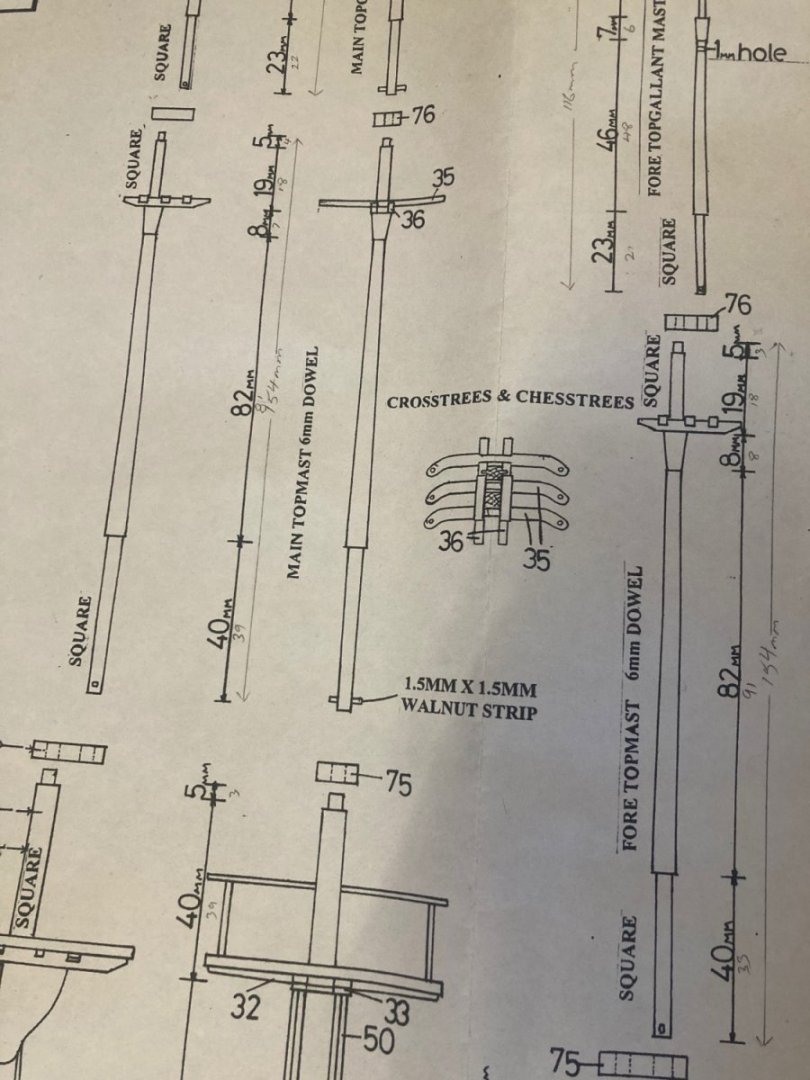
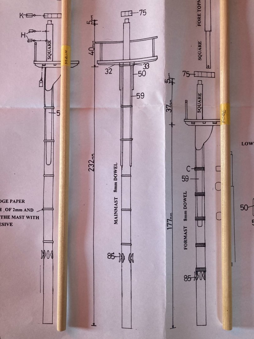
There’s a slight problem with the dimensions in the plans for the topmasts. the instructions state “The make-up of both masts is almost identical except for the height.” In fact, the fore-mast height (177mm) and main-mast height (232mm) is the only difference between the two. However... The fore topmast and main topmast are drawn differently. Whilst the overall length for both is 154mm, and the lengths are written the same, the fore topmast is out as much as 9mm when measured with a ruler. For a 1:1 drawing, that’s pretty poor. Every other mast dimension is consistently 1mm out. I’m perfectly fine with that, as it’s probably the difference between a 1:1 drawing and a photo-copy of one. Both the fore topgallant and main topgallant masts are identical in drawn and actual dimensions, so I’ll make two identical topmasts to the dimensions shown for the main mast. Problem solved.
-
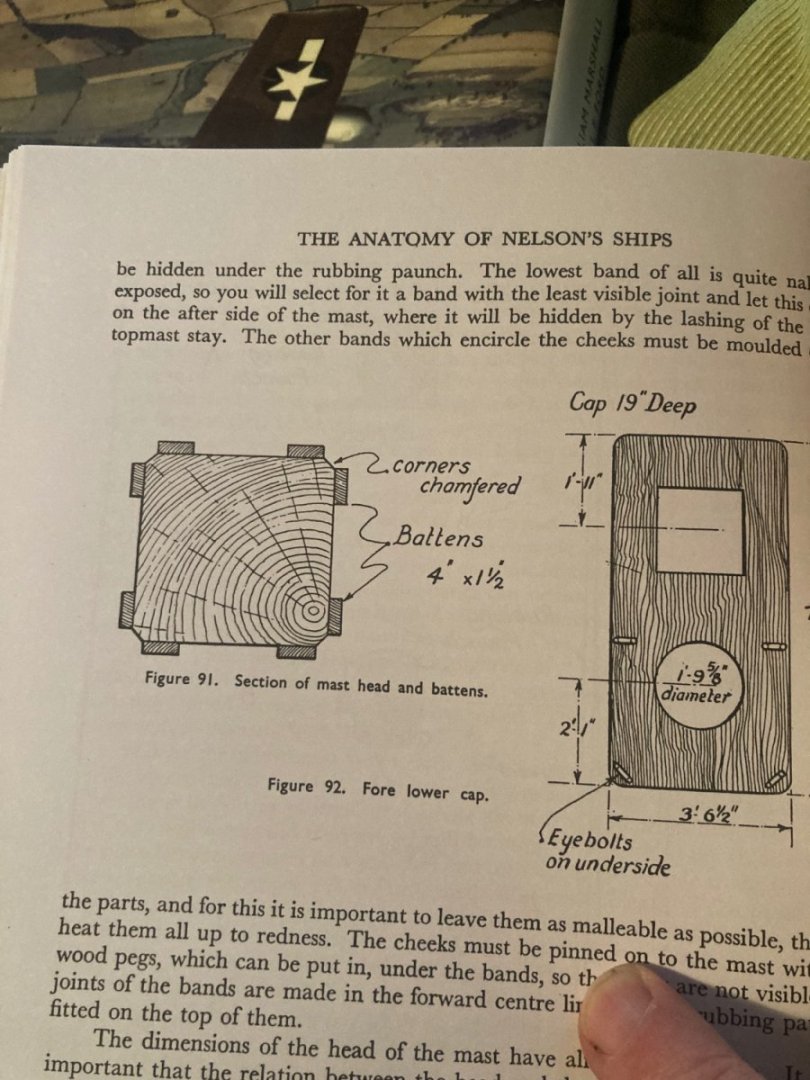
So then. Onwards and upwards. Literally. I’ve started shaping the masts with a combination of file and sanding stick. A question; In Longridge’s The Anatomy of Nelson’s Ships book, fig 91 (page 166) shows vertical battens fitted to the corners of the square mast-head. Would all the masting details shown in this book be applied to an Admiralty ship the size of the Supply?
-
Allan, that’s very interesting. It’s detail like this that I find fascinating, but I just don’t know where to find it. I would have thought the Supply had stern windows, but I quite like the ‘out of box’ look of her.
-
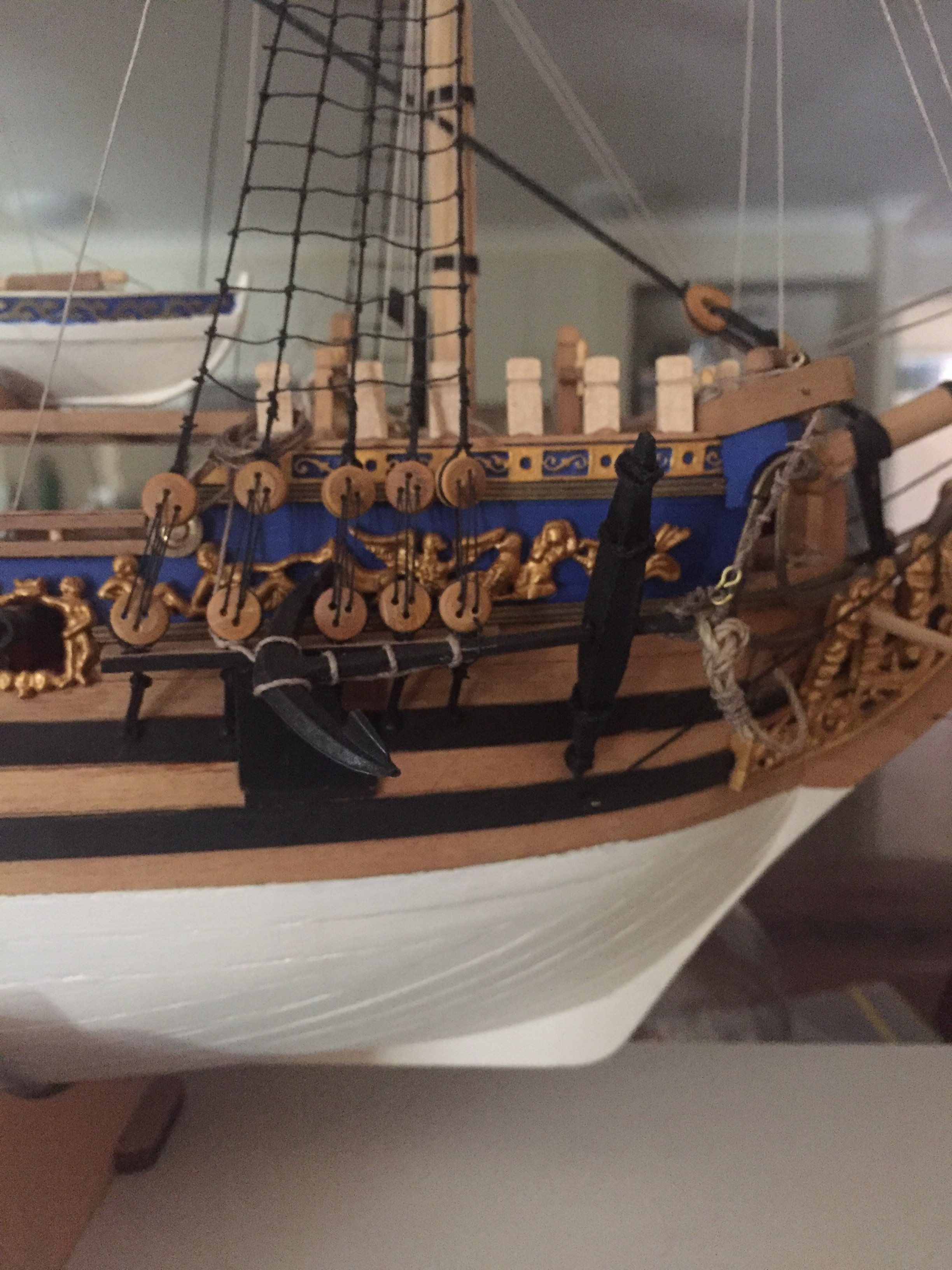
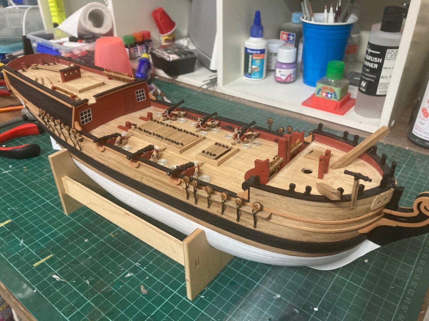
Thirty-odd deadeyes were finally fitted along the Supply’s chain-plates. I painted all the brass parts black to represent wrought iron.
-
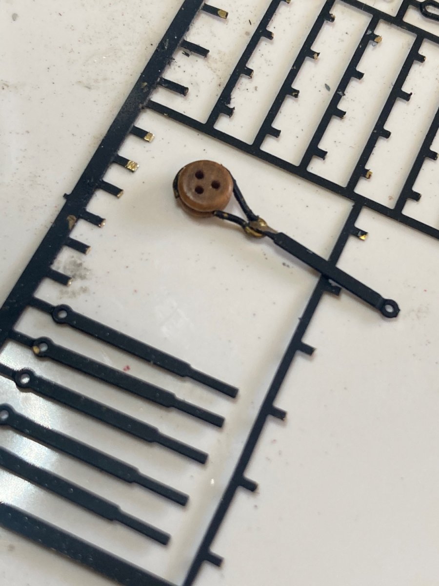
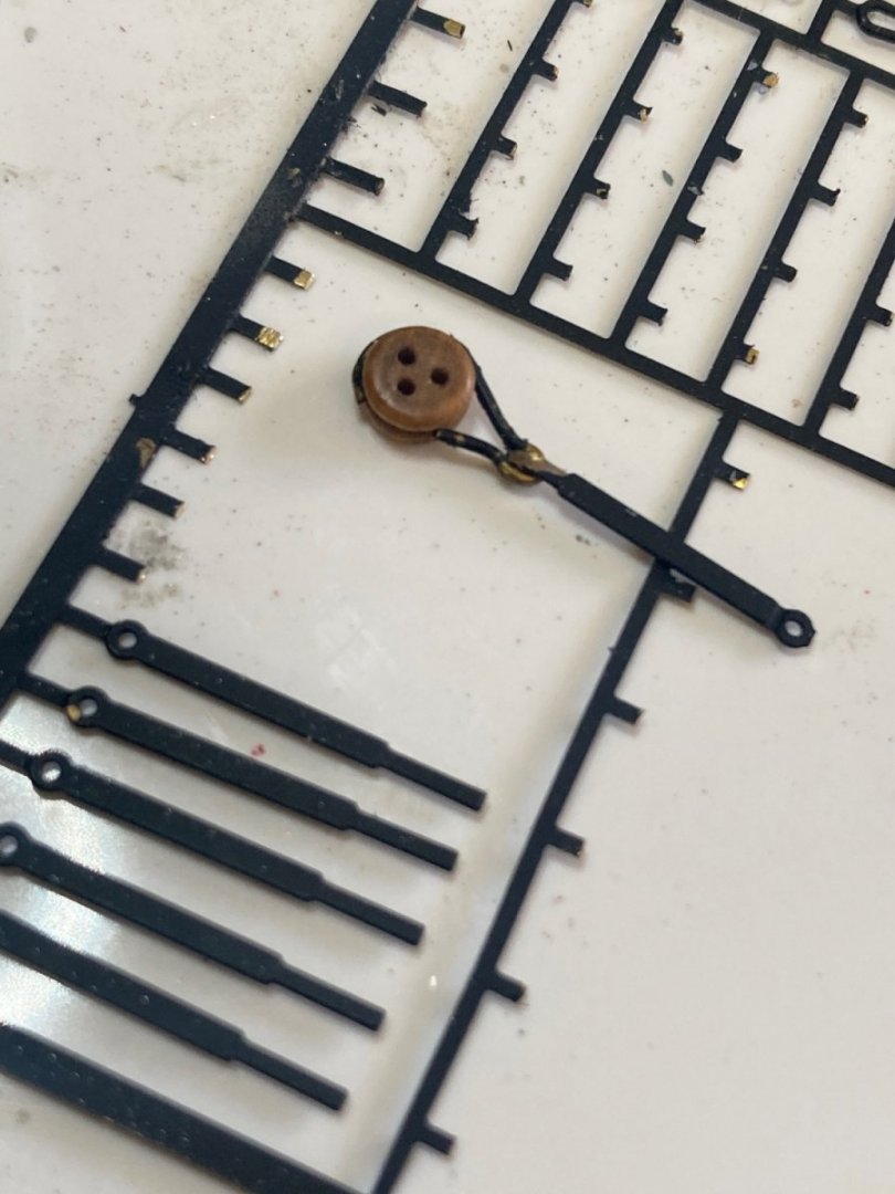
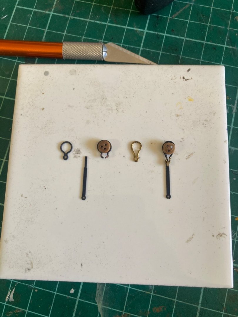
For six months now, I’ve been pondering what to do about a problem I’ve encountered with mounting the deadeyes to the chain-plates. Kit part 101 (5mm deadeye strops) are wire loops that surround the deadeyes, then have kit part 78 (deadeye straps) bend around their lower hoop. The trouble is the wire strops have a gap at the lower hoop after the deadeye is inserted. When you apply upwards tension to the deadeye, the copper strops simply pull out of the brass straps. This is why I haven’t progressed…I needed to fix this. I thought about using a two-part epoxy to glue them together, but I wanted the deadeyes to be able to pivot. On a recent trip to Melbourne (Australia), I dropped into “Float-a-boat”, the Caldercraft supplier, to have a look at alternatives. I bought three packs of ten replacement deadeyes and straps at $AU15 each. In this photo, from left to right: The kit supplied strop, part 101. The kit supplied strap, part 78. The 5mm deadeye installed in the strop. The aftermarket strop, and The new strop fitted to the strap. i decided not to use the rest of the brass chains that came with the new parts.
-
The notch I think you’re referring to on the cabin facia is for the bulwark and capping rail. The foredeck facia has no notch because it’s shorter than the height of the bulwarks. You’ll be fine. Enjoy your build.
-
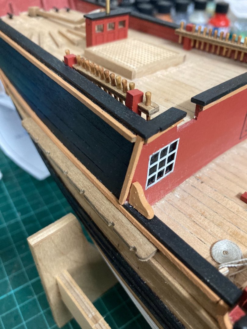
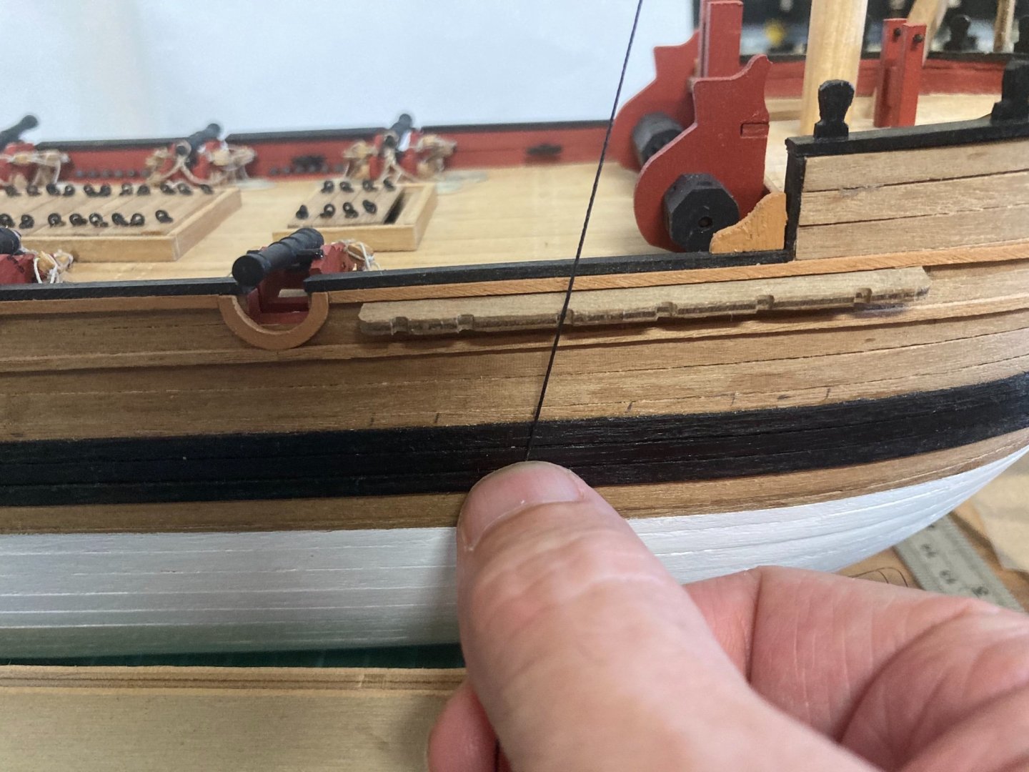
My second error was the cabin wall facia. I meant to plank the main deck, then do the hull’s first planking, then fit the facia (part 57) and sand its outside edges flush with the first planking. Then, when the second planking’s completed, the hull would have extend over the top of the facia’s outside edges and sanded flush. If I did that, the vertical yellow ochre strip in my photo would have been flush with the top yellow strip running aft. In reality, my errors aren’t really noticeable. But you will need to have everything on the sides of the hull flush and contoured to enable a nice, smooth hull plank run.
-
Hijack away, I wouldn’t care in the slightest. Yes, the facias should be fitted first to frame 3 (forecastle aft) and frame 8 (cabin forward), then sanded flush with the outside edge-lines of those frames. In reality, I fitted both my facias after the deck planking was completed, but I made two mistakes by doing that: If I fitted the smaller, foredeck facia first, I would have sanded its top edge down, flush with the fore-deck ply (part 22). Then the fore-deck’s planks would have covered over the forward facia’s upper edge. Mine looks ok, but I regret not continuing the forecastle planks over the top of the small facia.
-
Thanks very much! Humbly appreciated.
-
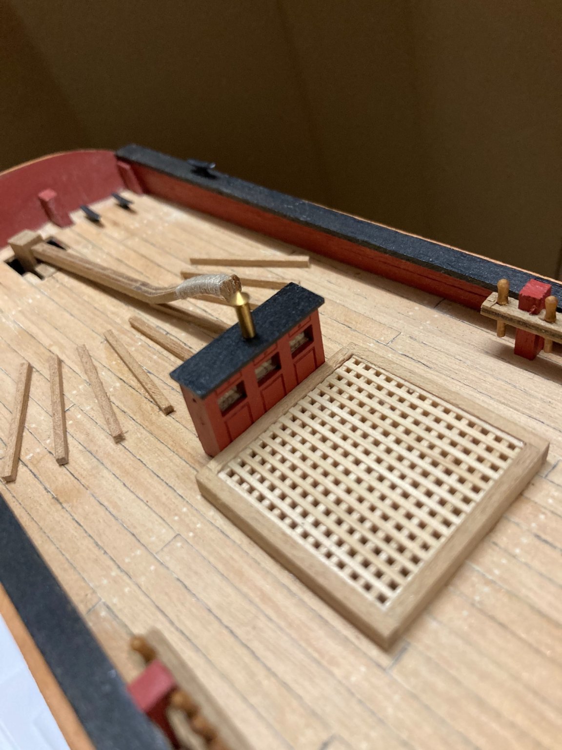
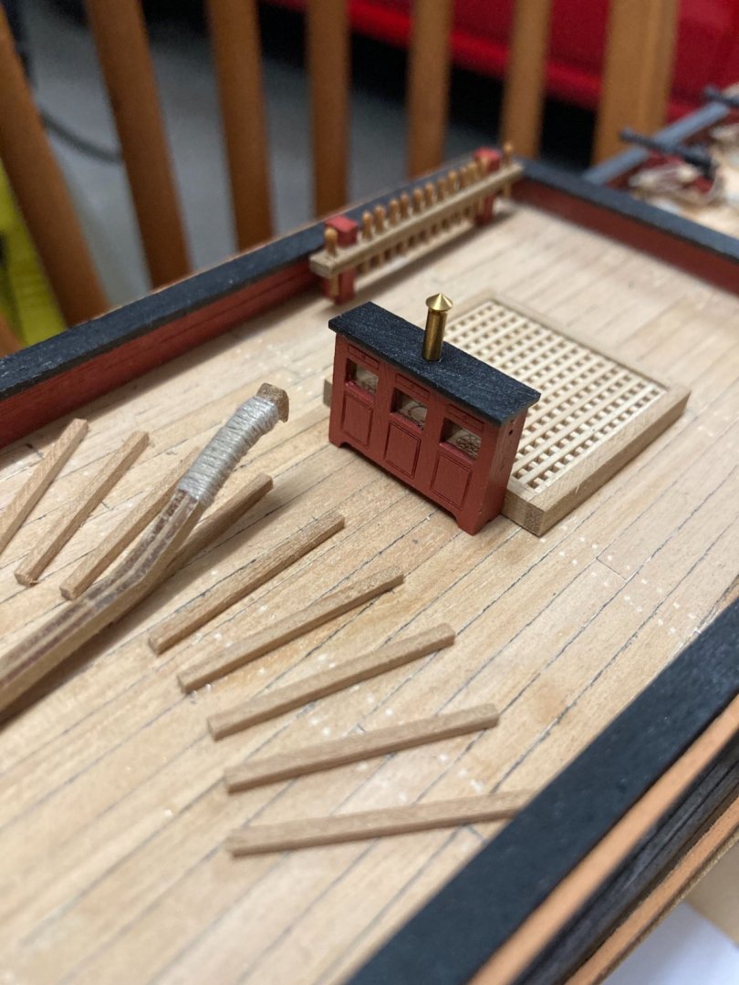
The binnacle’s complete. I think it’s a worthwhile addition to the kit. I decided to leave the brass chimney unpainted. I’ve placed two pieces of thin polycarbonate inside the binnacle to simulate glazing. It looked odd without. I hadn’t bothered glazing the other windows of the ship, but because they have black backgrounds, I still don’t think it’s necessary.

-
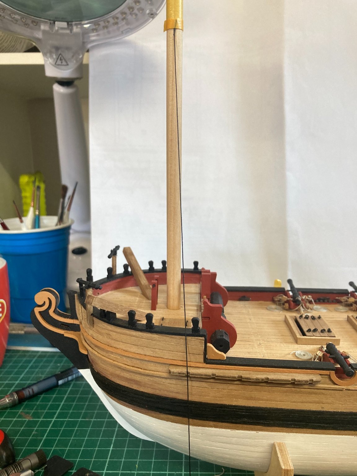
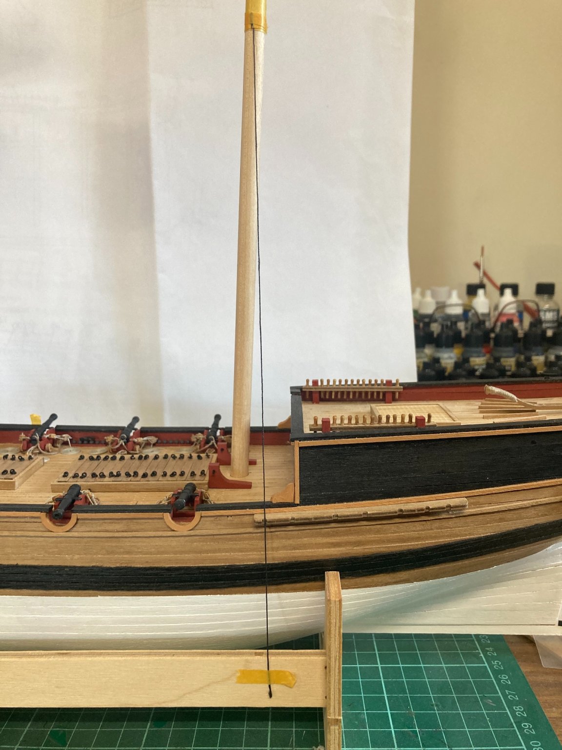
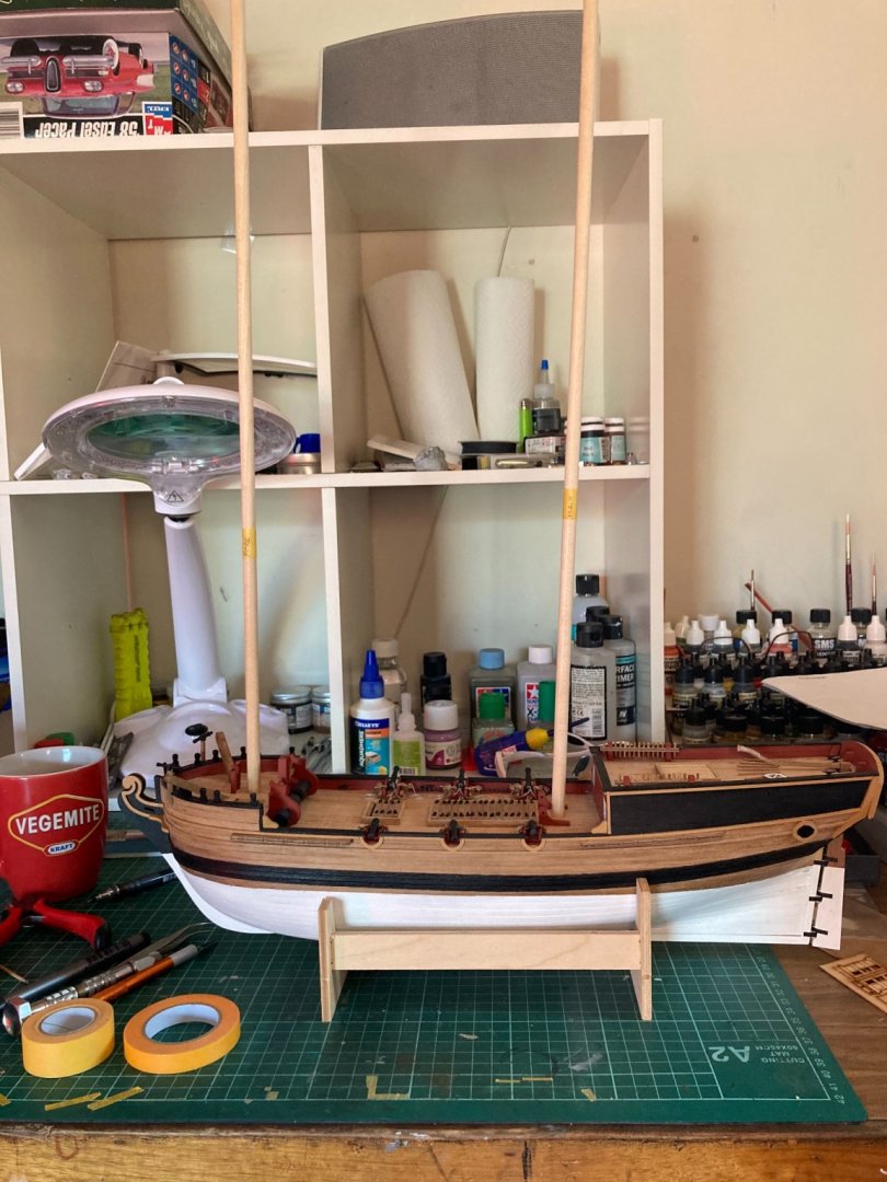
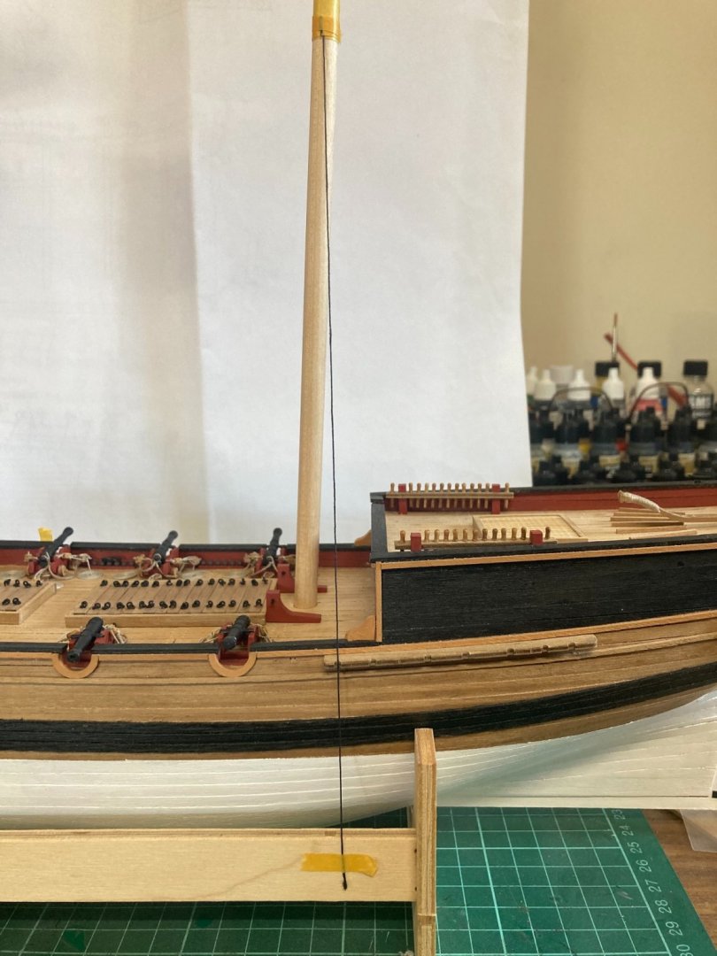
I measured the height of the tops from the plans, then taped a cord at that height. Then I dropped each mast into its hole, pulled the cord into each strop recess on the chain-plates and marked the hull just above the main-wale. My rearrangement of the aft chain-plate’s locations worked out well: Both fore and main mast’s foremost shroud’s ended up being just off the vertical. The aft sweep of the masts themselves is, of course, governed by their slots in the false keel.

-
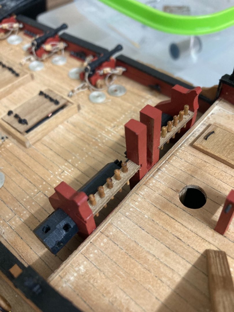
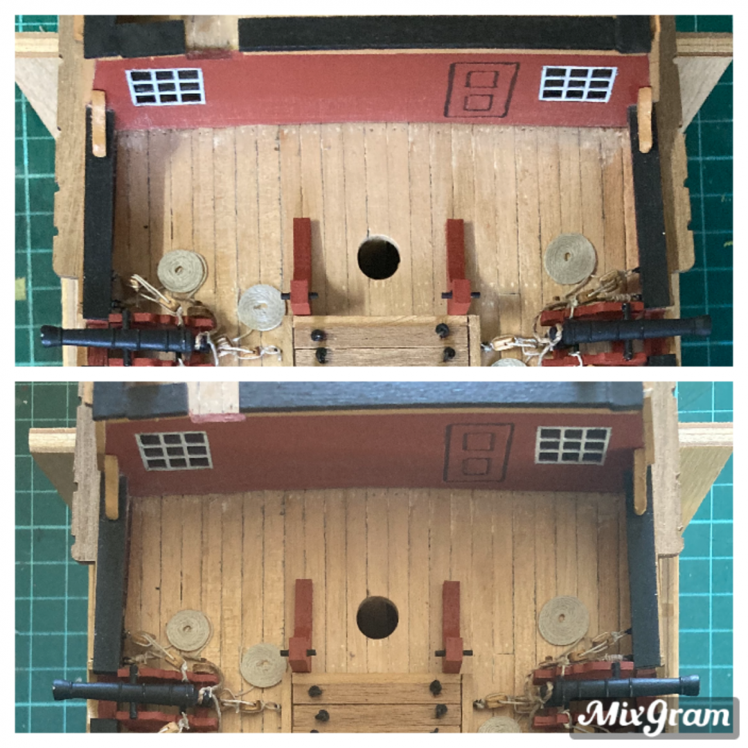
Flipping all four chain-plates drastically altered the shroud’s angles and measurements, so both main-mast chain-plates had to be moved rearwards to compensate. You can see the difference in the photos; (top- before, bottom-after). The main-mast rakes aft a few degrees more than the fore-mast. Now I’ve done that, both mast’s forward-most shrouds begin at the mid-point of each main-top and drop down to finish in-line with the rear edge of the mast. Long-winded, difficult to explain but easy to achieve.
-
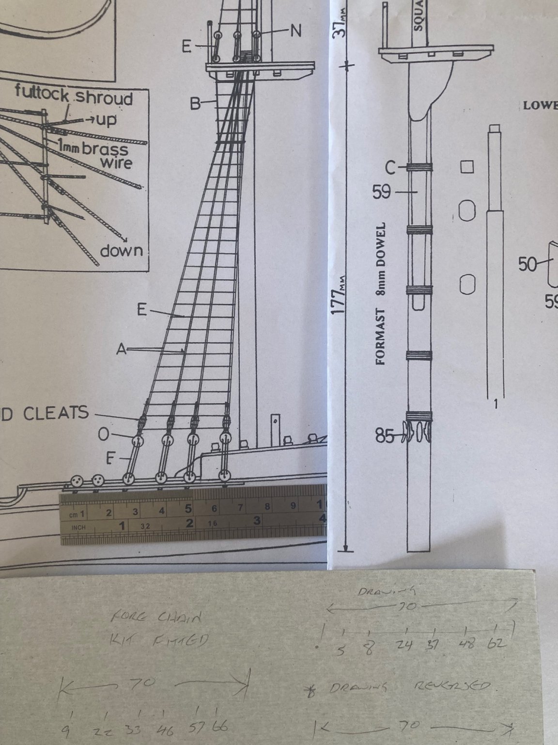
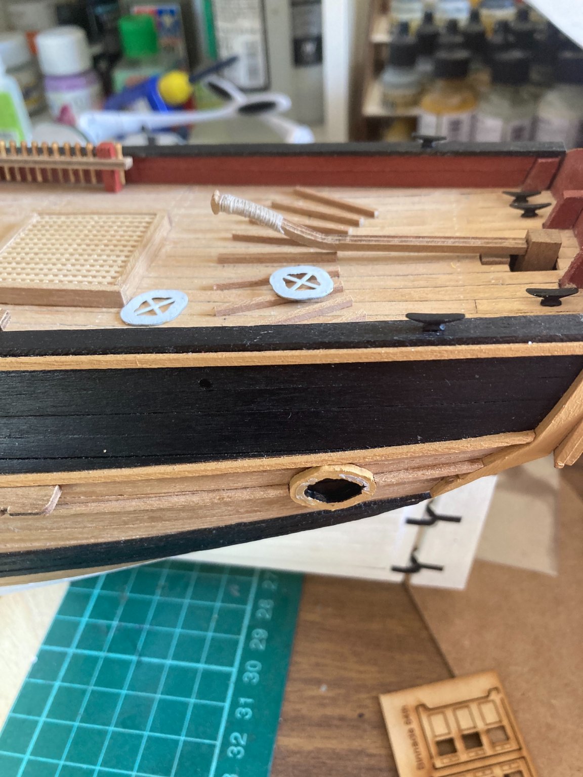
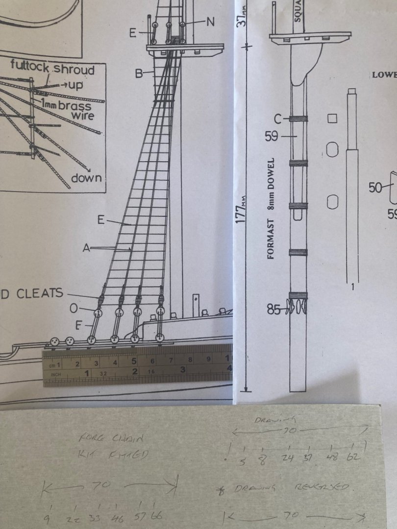
All that remains on the hull now are fitting the shroud’s lower dead-eyes, the poop-deck ladder and the after-market binnacle. Then I work forwards and upwards. So….time for a story. The lower dead-eye’s chain-strops are to be fitted with each one slightly angled in-line with its shroud. In order to gauge that angle, I dropped each mast-dowel into its hole and measured up to the height of the lower mast-top from the plans. Then I secured a rope at that height and bought it to meet its lower attaching point. Odd- the angles didn’t really match the drawing. Out came a ruler… I measured the total length of the forward RHS chain-plate: 70mm. Correct. The rear’s 80mm. I measured the distance from the aft edge of the plate to each pre-cut strop-slot: 5mm, 8mm, 24mm, 37mm, 48mm and 62mm. Then I measured the same on my kit: 9mm, 22mm, 33mm, 46mm, 57mm & 66mm. Hmm. Then I flipped the ruler upside-down and measured from the top RHS to the strop-slots: 8mm, 22mm, 32mm, 46mm, 56mm & 64mm….Riiiiight! I had fitted the forward chain-plates upside-down! Now I measured the rear chain-plate… I had fitted that upside-down, too! It’s very easy to do- they look the same mounted each way. They were all relatively easy to remove using bent long-nosed pliers as a lever.
-
I previously hadn’t painted black inside the quarter-windows. They were bothering me more than I thought they would so I removed them and… you know…

-
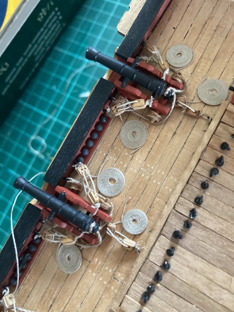
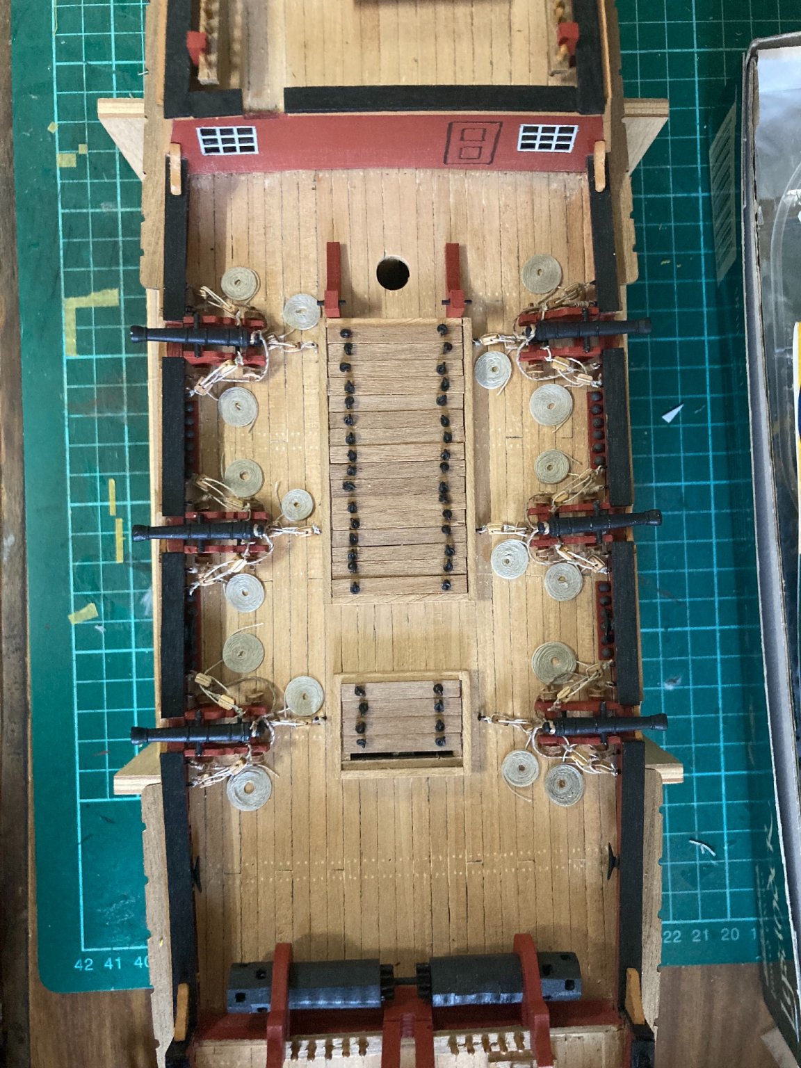
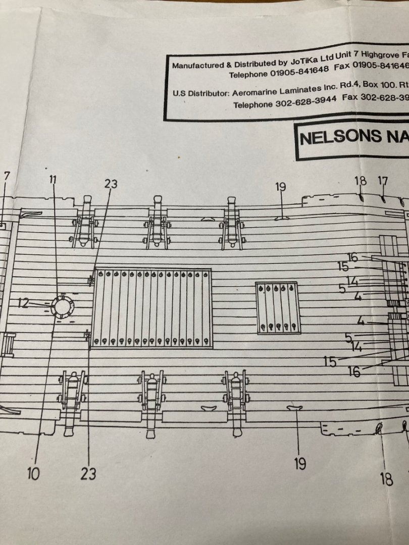
Main deck’s now complete. Feedback, please? I’d appreciate honesty- Are these coils oversized?