Jobbie
-
Posts
220 -
Joined
-
Last visited
Content Type
Profiles
Forums
Gallery
Events
Everything posted by Jobbie
-
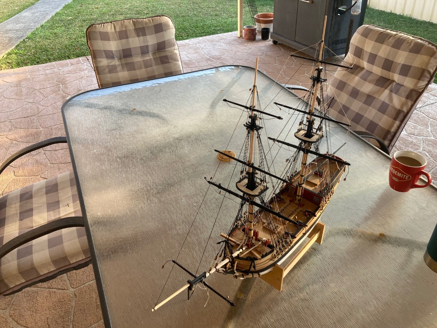
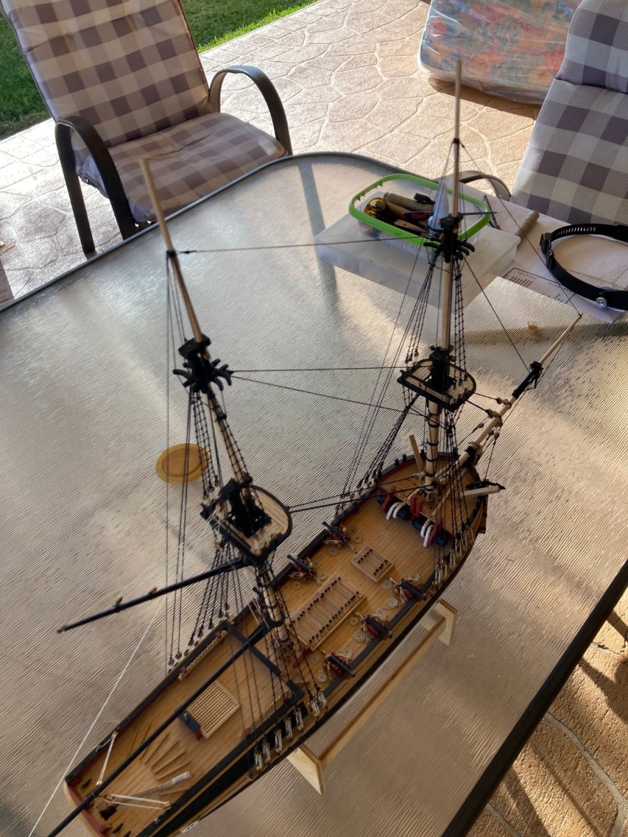
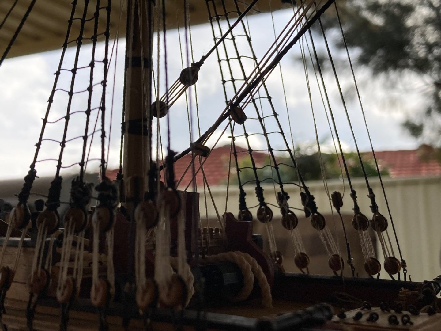
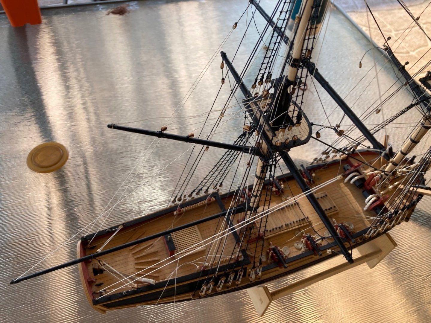
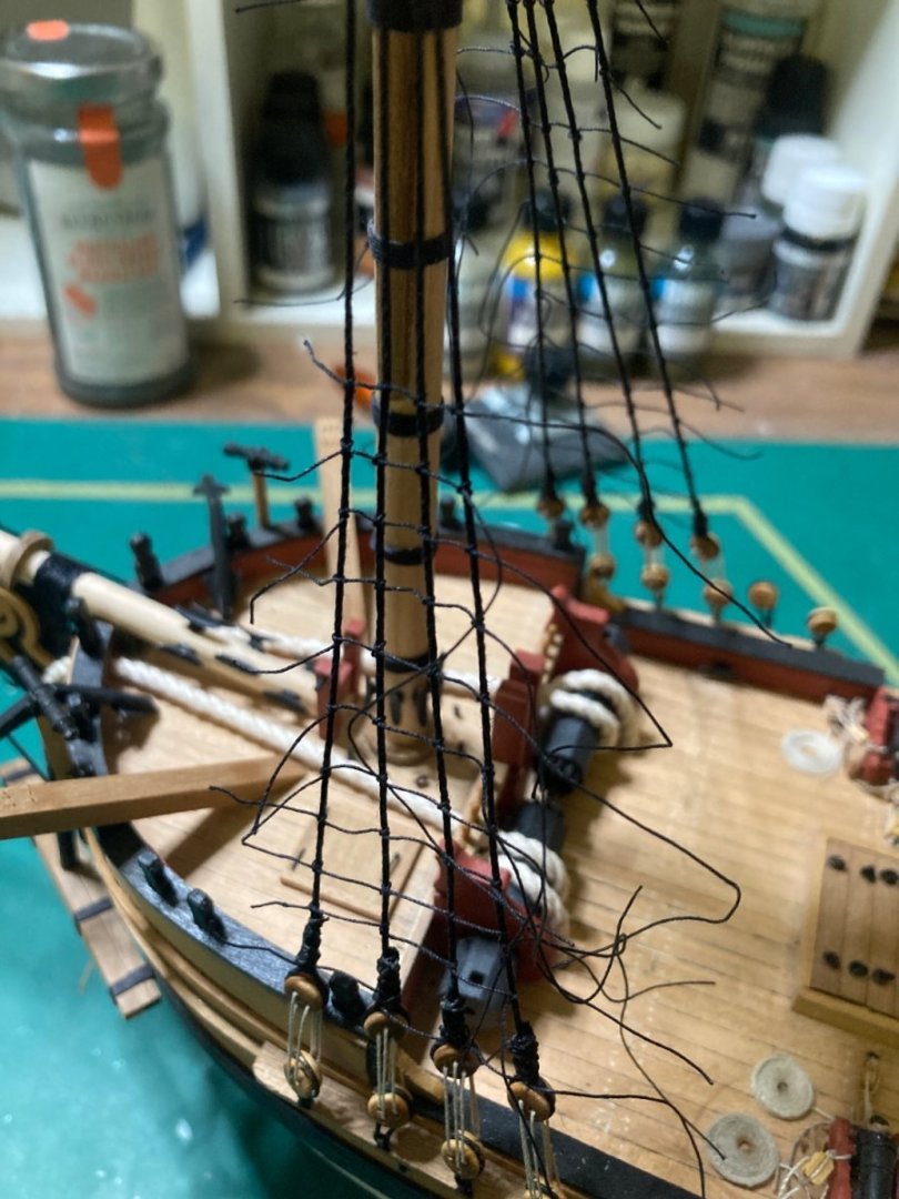
 I’ve now completed the rigging for the lower yardarm on both masts. Both the foremast’s main and topsail braces run through blocks down along the main-stay. They get very close to each other but don’t rub on each other when rigging according to the plans. I don’t particularly like the way these port and starboard braces run through double blocks together above the windlass because their working load wouldn’t be parallel to the pulley’s axle. But I’ll leave it to match the plans as a reference for other builders of this kit. All the rigging except for the spirit-sail yard is now complete. Coils of rope need to be placed on the pin-rails where ropes are lashed and the anchors both need suspending on their cat-heads….then this project’s complete.


-
Yes, I’m getting there. I’m simply loving this build. I’m impressed with your list of builds, too. I’m an avid plastic scale modeller, too. See “The scale model twins” on Facebook.
-
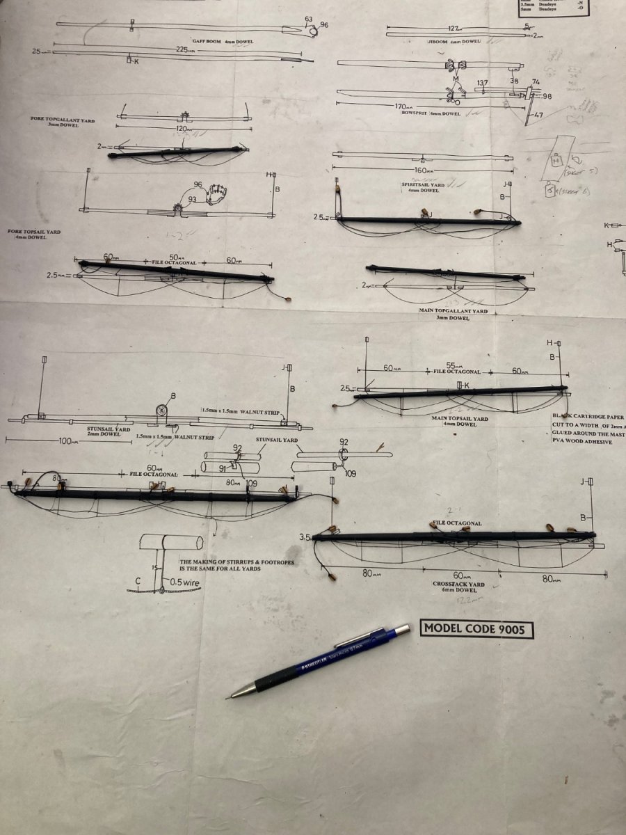
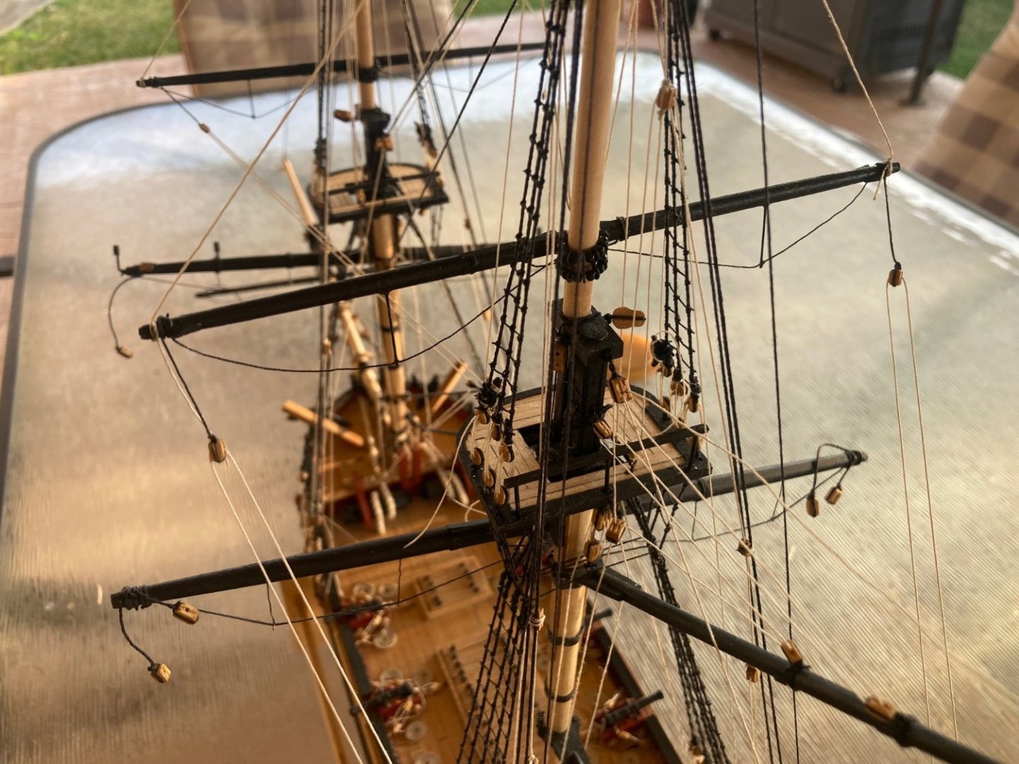
The top four yardarm’s are now complete. I found no real issues with their rigging plans. However, I’ve relocated the main mast’s top-sail yard’s brace-tackle blocks from the aft bulwarks to the transom in order to hopefully avoid interference with the lower, larger cross-jack yard’s braces.


-
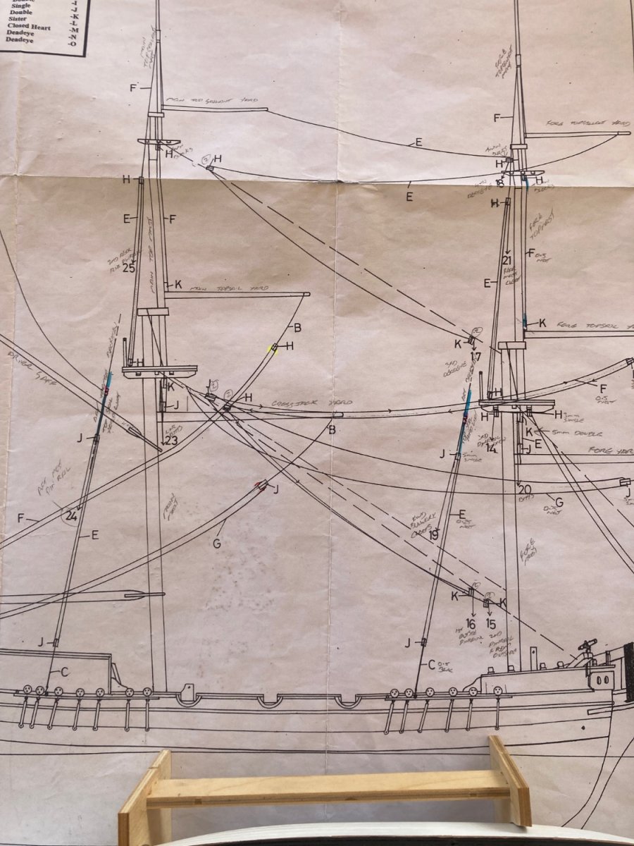
The foremast’s topsail yard’s braces, as per the kit’s rigging plan. They’re shown running down along each side of the main-mast’s back-stay then through a double block before belaying at the fore-mast pin-rail.


-
Oh, you’re absolutely correct. I’ll go back and amend my previous post. Thanks.
-
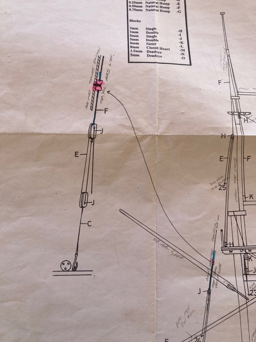
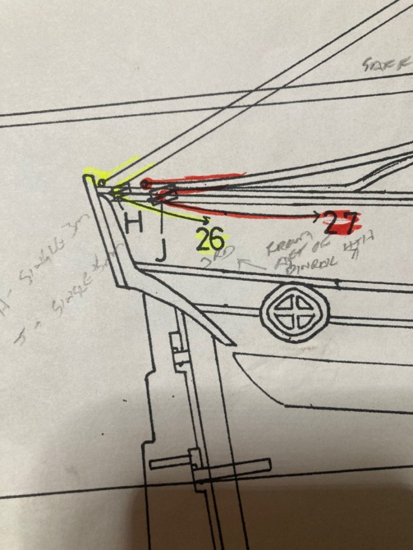
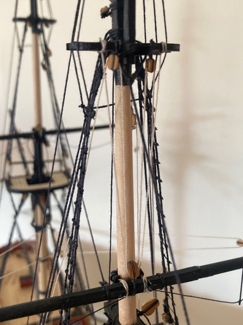
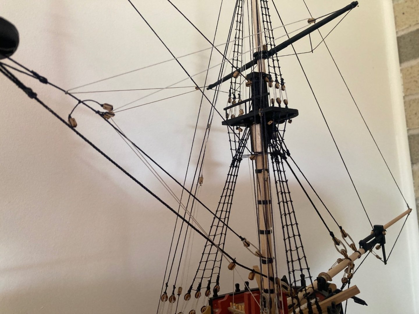
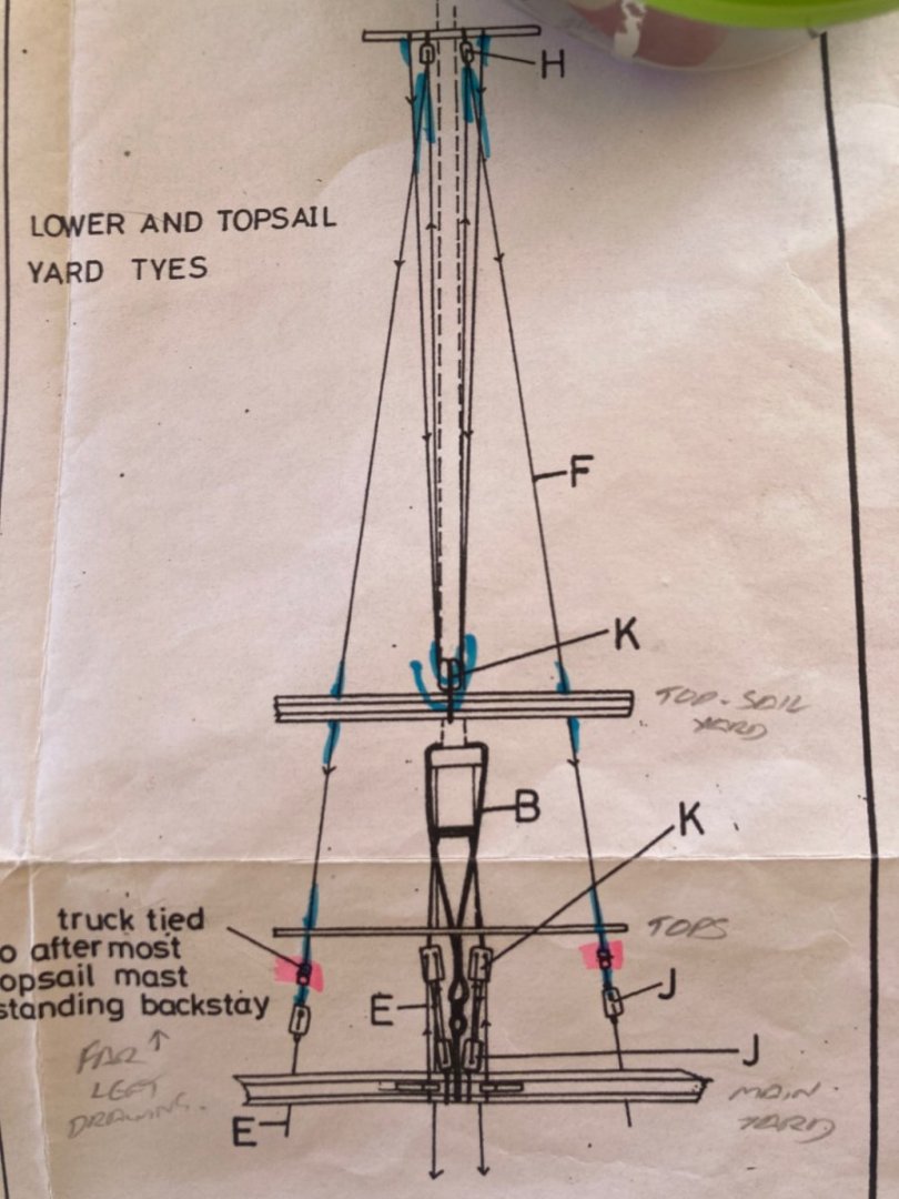
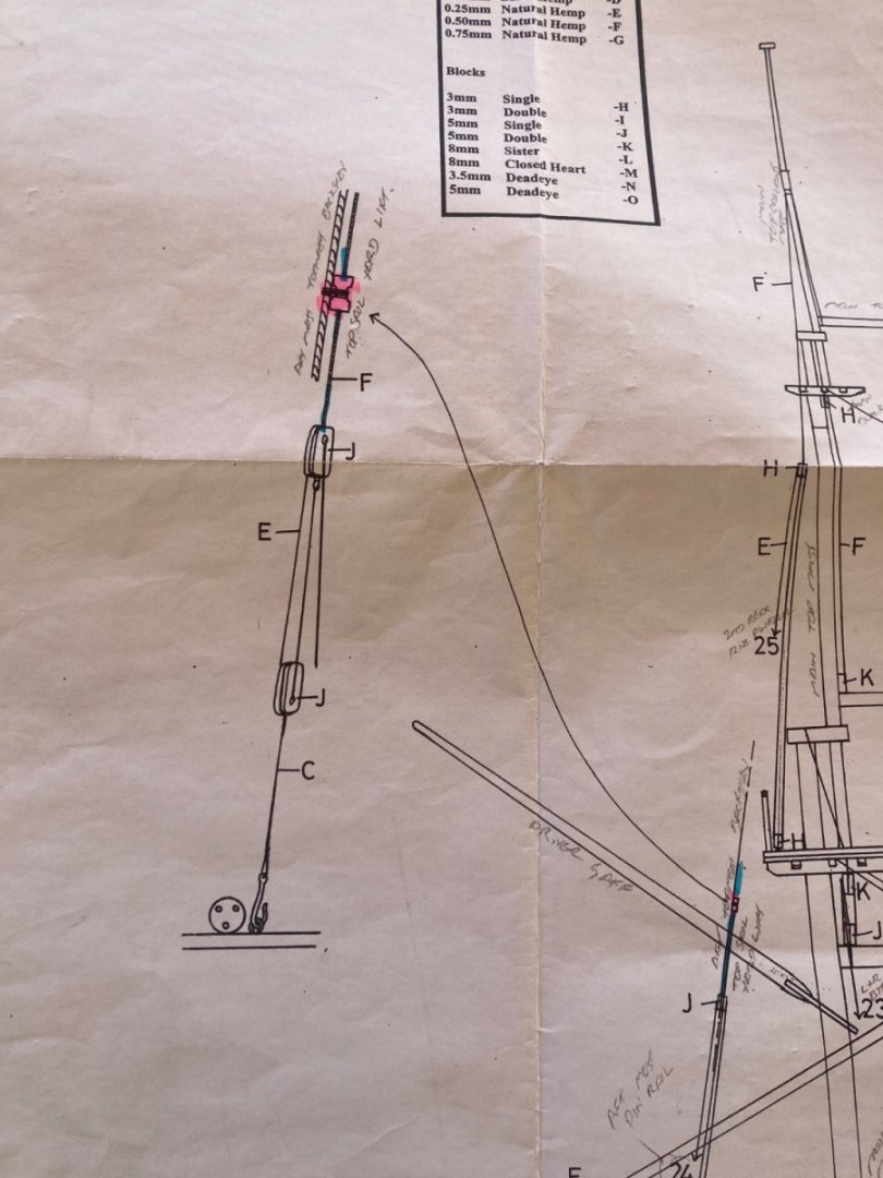
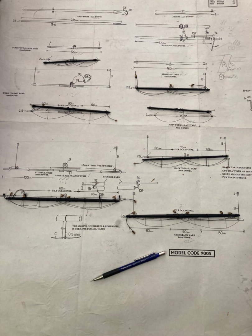
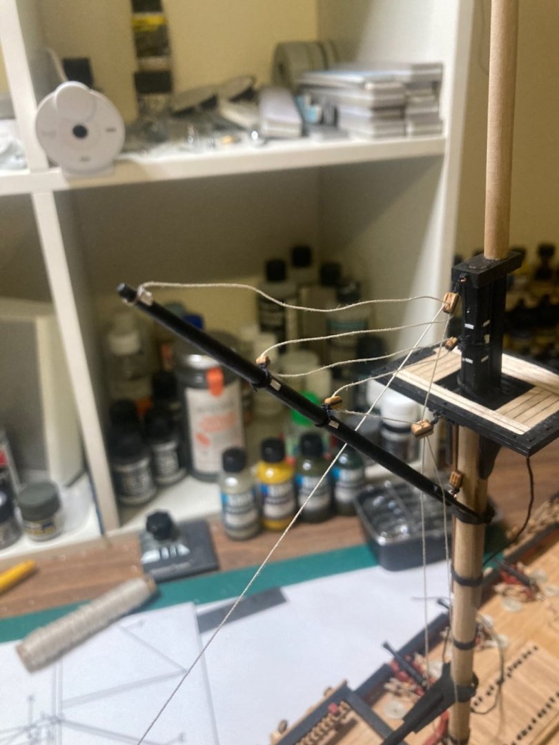
There’s a rather confusing, not clearly described or drawn part of the running rigging plan on sheet 6. I believe I’ve worked it out, so I’ll share it here to possibly aid other builders. The lifting tackle (tyes) for the top-sail yards (the two middle yards) start off with the port and starboard ropes being tied to the upper forward-most cross-trees. From there they drop down to the yard, pass in opposite directions through a double block in the middle (K; 5mm double block), then back up to the cross-trees. Then they pass through two separate blocks tied to the cross-trees (H; 3mm single block) and down through a truck: a hole drilled through a section of square wood that’s been lashed to the aft-most top-mast back-stay. (6th deadeye from the front on the fore-mast, 7th deadeye from the front on the main-mast. I used 1.5mm x 1.5mm walnut, cut into 3mm lengths for the 4x trucks. From there, the top-sail yard tyes terminate at a block (J; 5mm single block). A second block is lashed to the chain-plates. The final hauled rope on each side passes through both blocks and gets tied off: Forward inner bulwark cleat for the fore, aft-most belaying pin on the quarterdeck for the main. I’ve probably confused you more, haven’t I?

-
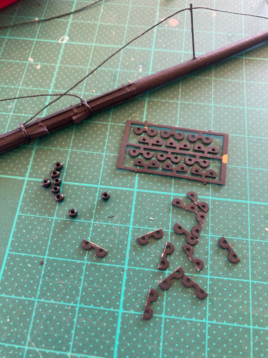
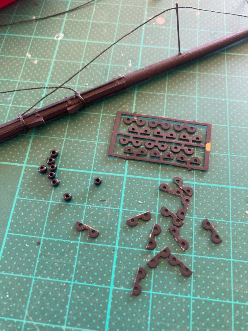
The brass topsail yard’s parral ribs have been airbrushed with Vallejo black primer before assembly with the parral trucks (beads).
-
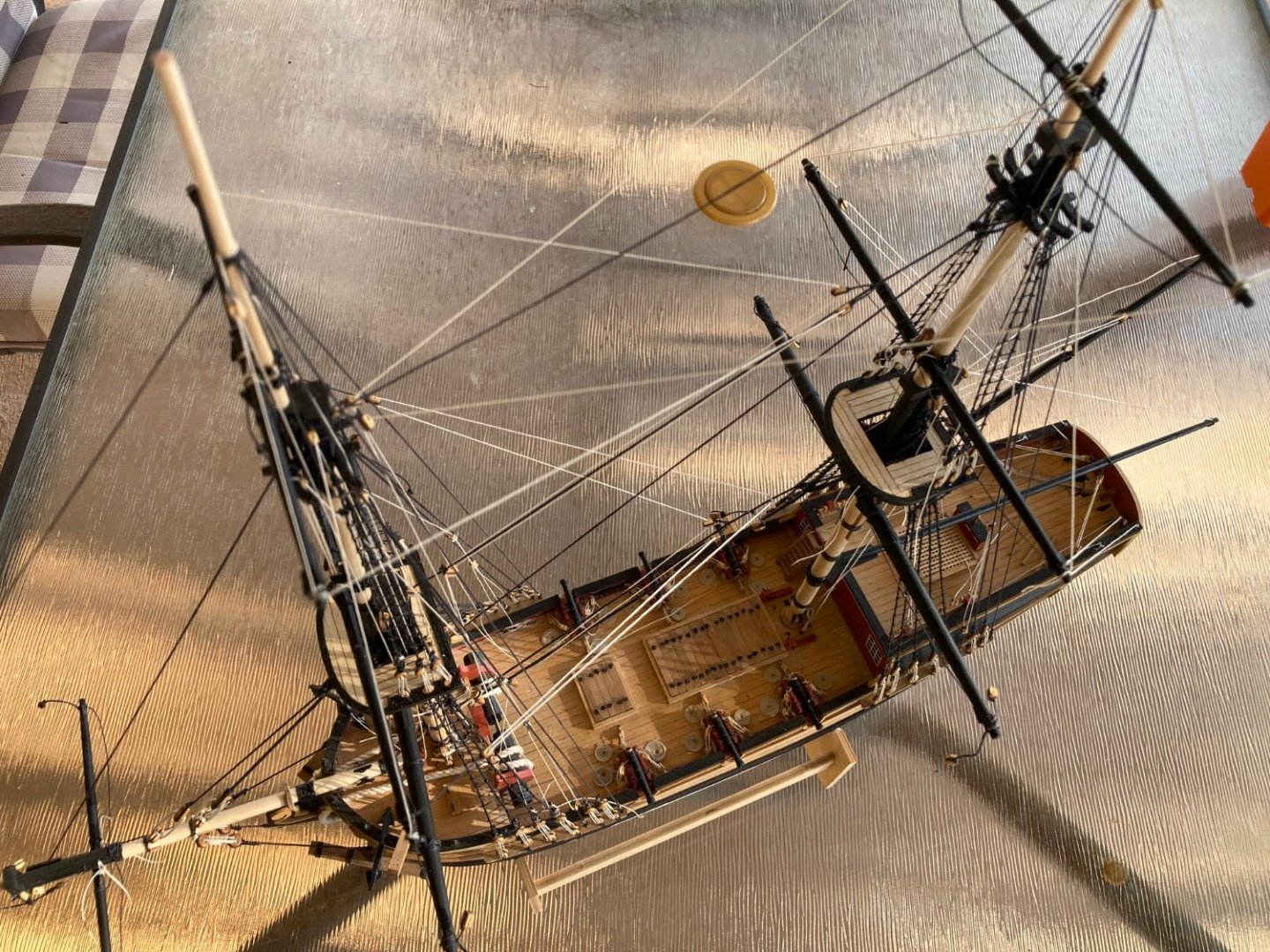
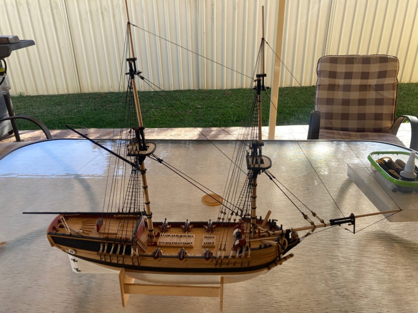
All the standing rigging has now been completed with no real problems. The yard-arms had been completed a few months ago. Time to hang them.

-
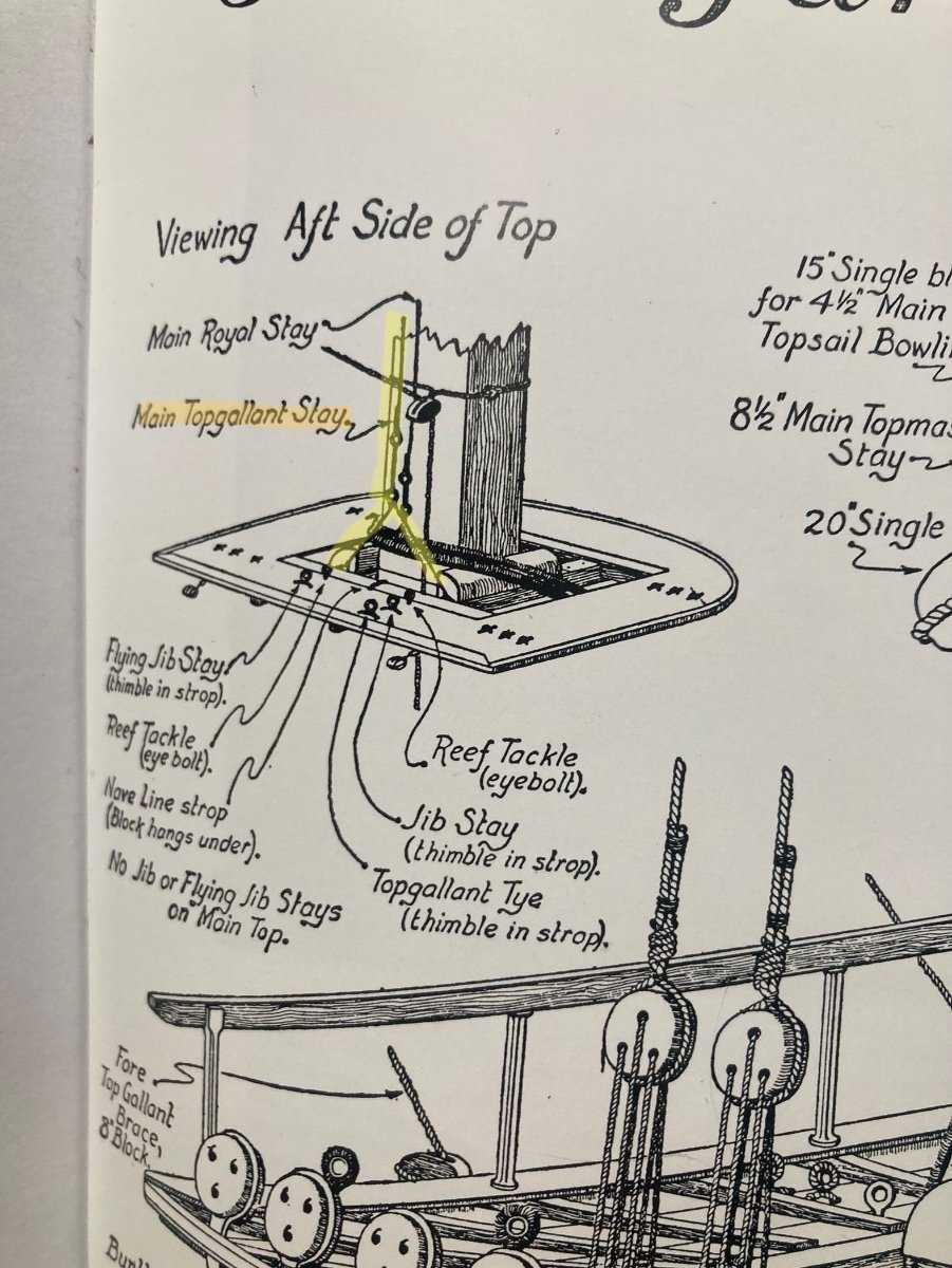
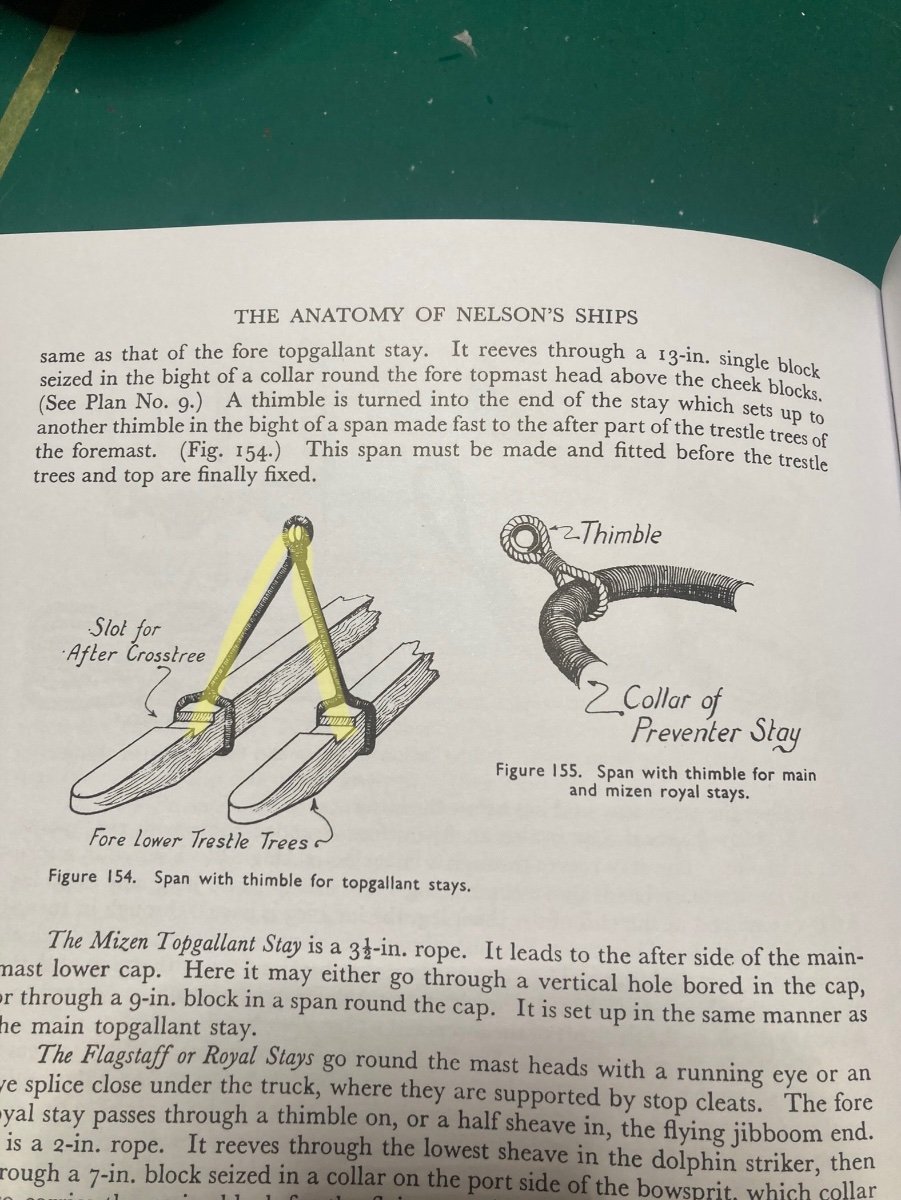
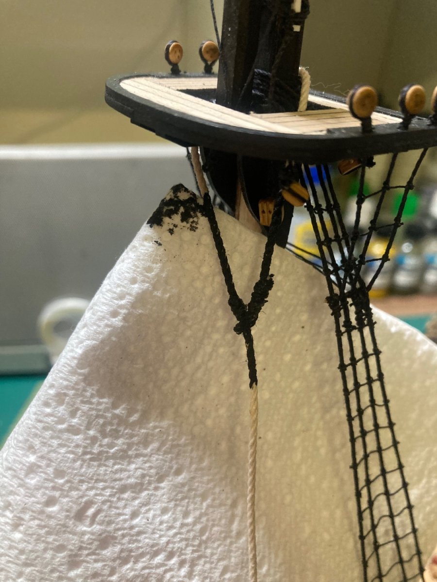
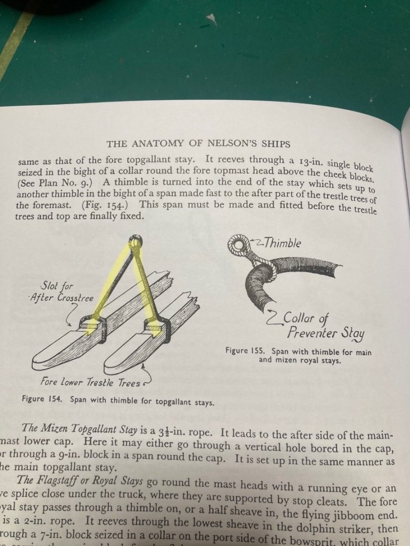
The termination of the main topgallant backstay was easier than expected. I followed the book’s method of a vee-stirrup on the fore-top. The main topmast’s backstay drops through the port-side lubber’s hole.

-
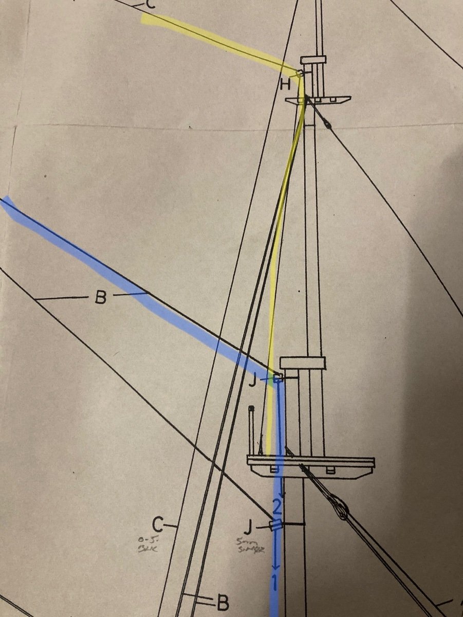
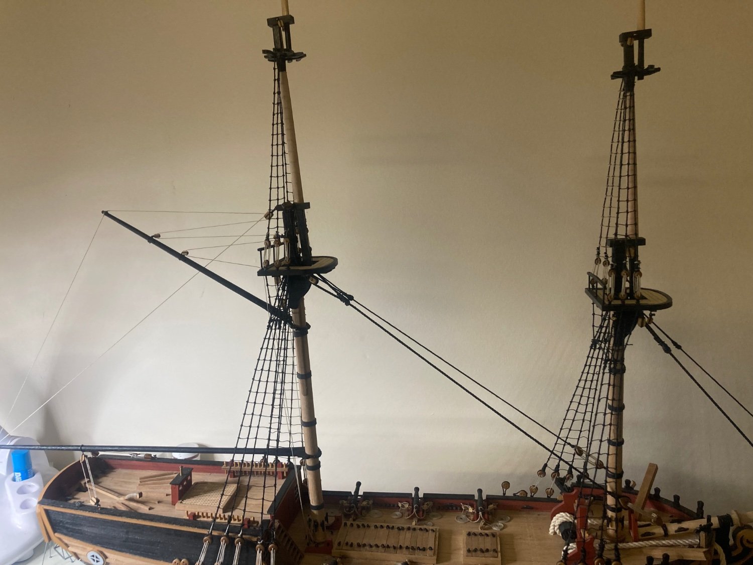
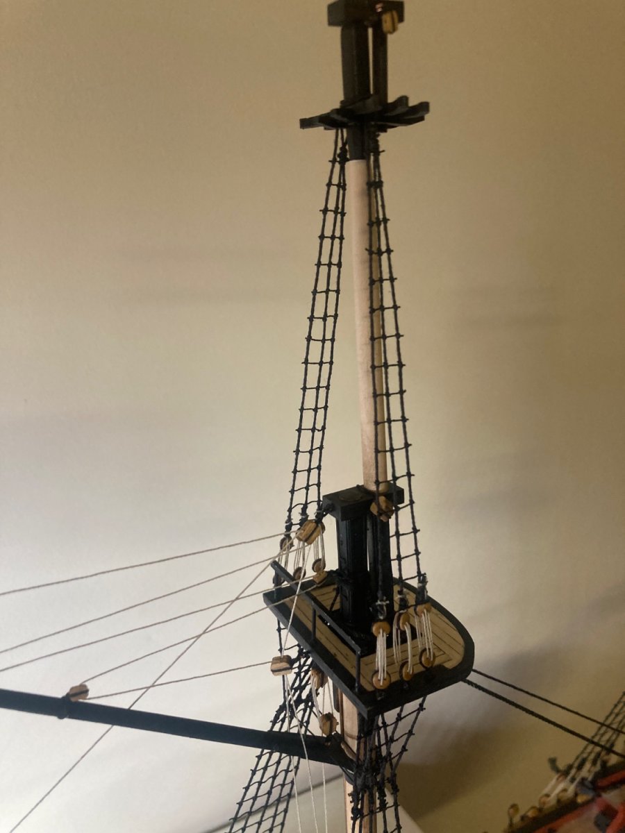
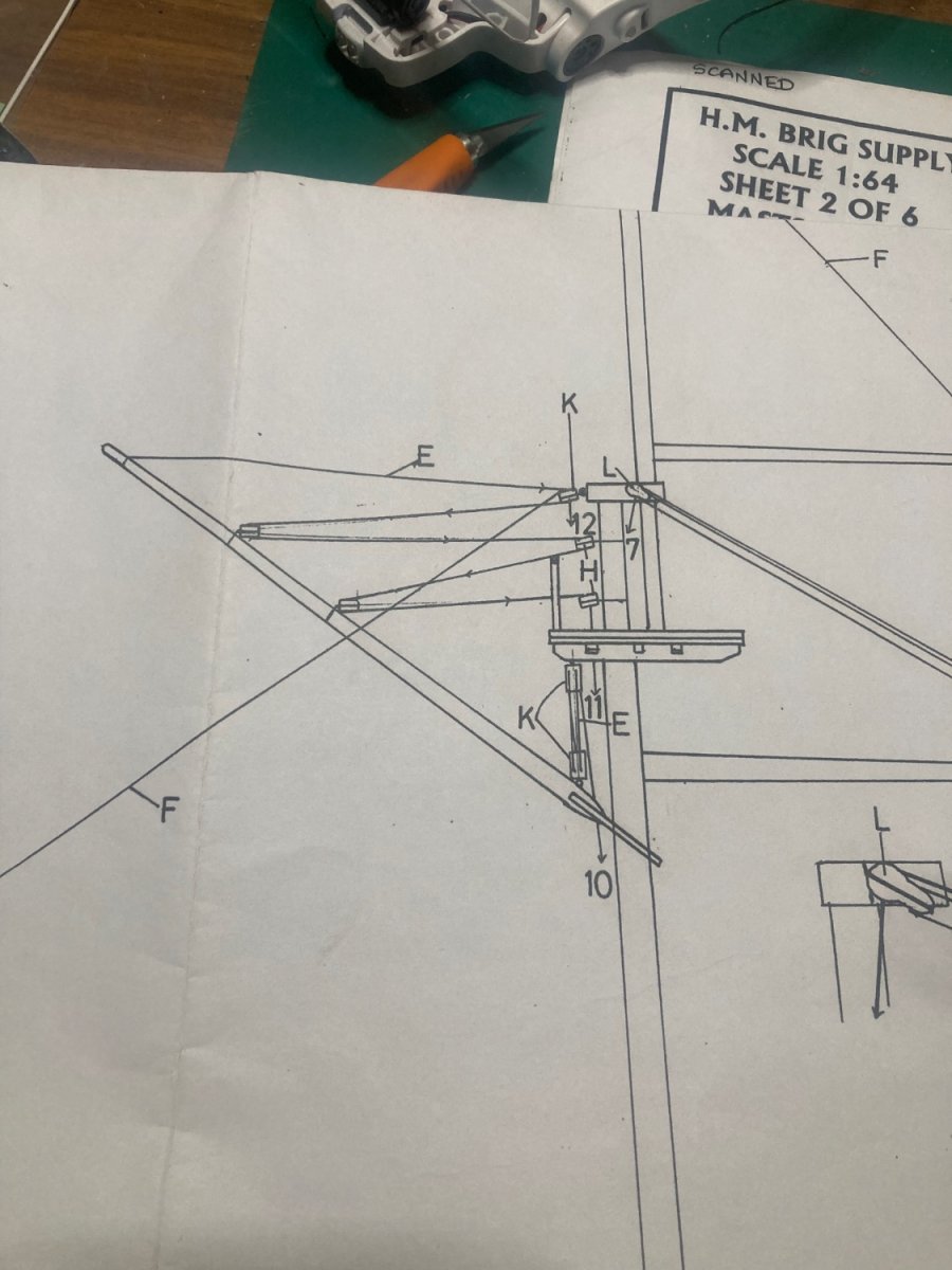
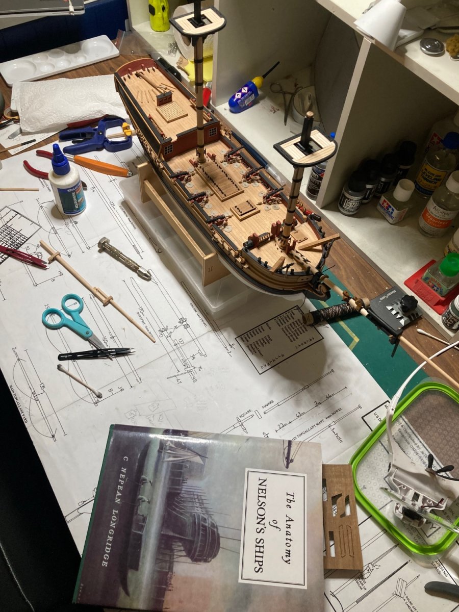
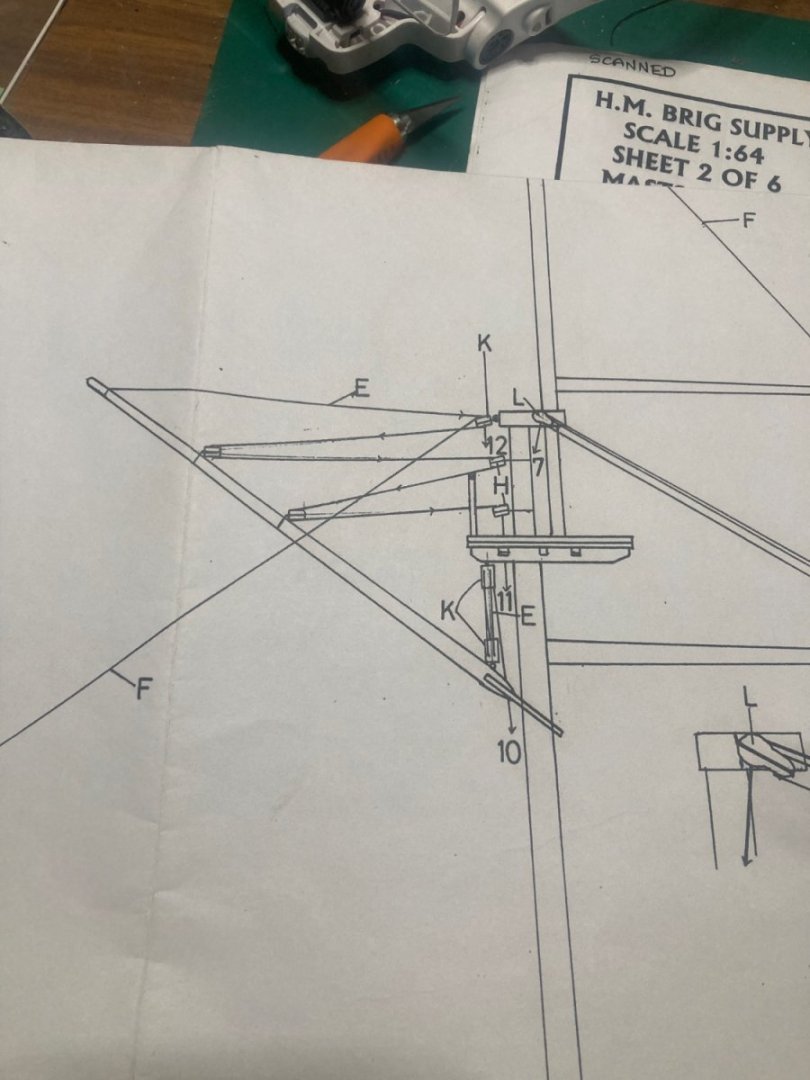
Oh, Great Oracle, a question…. Main topgallant backstay. My plans for Caldercraft’s 1:64 HM Brig Supply show the stay (highlighted in yellow) terminates on the fore-mast’s top. C. Nepean Longridge’s Anatomy of Nelson’s Ships book only really relates to HMS Victory. It shows the main topgallant stay terminates at a v-shaped stirrup lashed to the foremast trestle-trees which support the fore-top. Would there be a different termination method on smaller logistics vessels such as the Supply? Also, for bonus points; the main topmast’s backstay (highlighted in blue) show the line passes through a block at the masthead, then passes through the top to terminate at the deck. As there’s no hole in the platform behind the masthead, how would I do that? Drill a hole?


-
I’ve now completed the top-mast’s shrouds. I’ve been using some leftover Artesania Latina black 0.25mm rope for the ratlines, but I’ve finally run out of it. So the fore topmast’s port’s ratlines are done with the Caldercraft supplied natural 0.25mm rope. They’re soon to be dyed black with Indian ink. I’d done a test; one of the lower ratlines was natural colour, then dyed black. I honestly can’t remember which one….So, that’s good! On to the topmast’s backstays.

-
Funny...I found your build of the Supply while looking for guidance of the self-same rigging! Your build looks very nice indeed. Well played, that man!
-
The fore-stay and main-stay are 1.5mm rope. I’ve dyed them black with Indian ink on a paint brush.

-
I’ve completed the main-mast’s shrouds and ratlines. The futtock shrouds and catharpins have been finished as well. I’ll fit the main and fore-stays before moving onto the topmast shrouds.


-
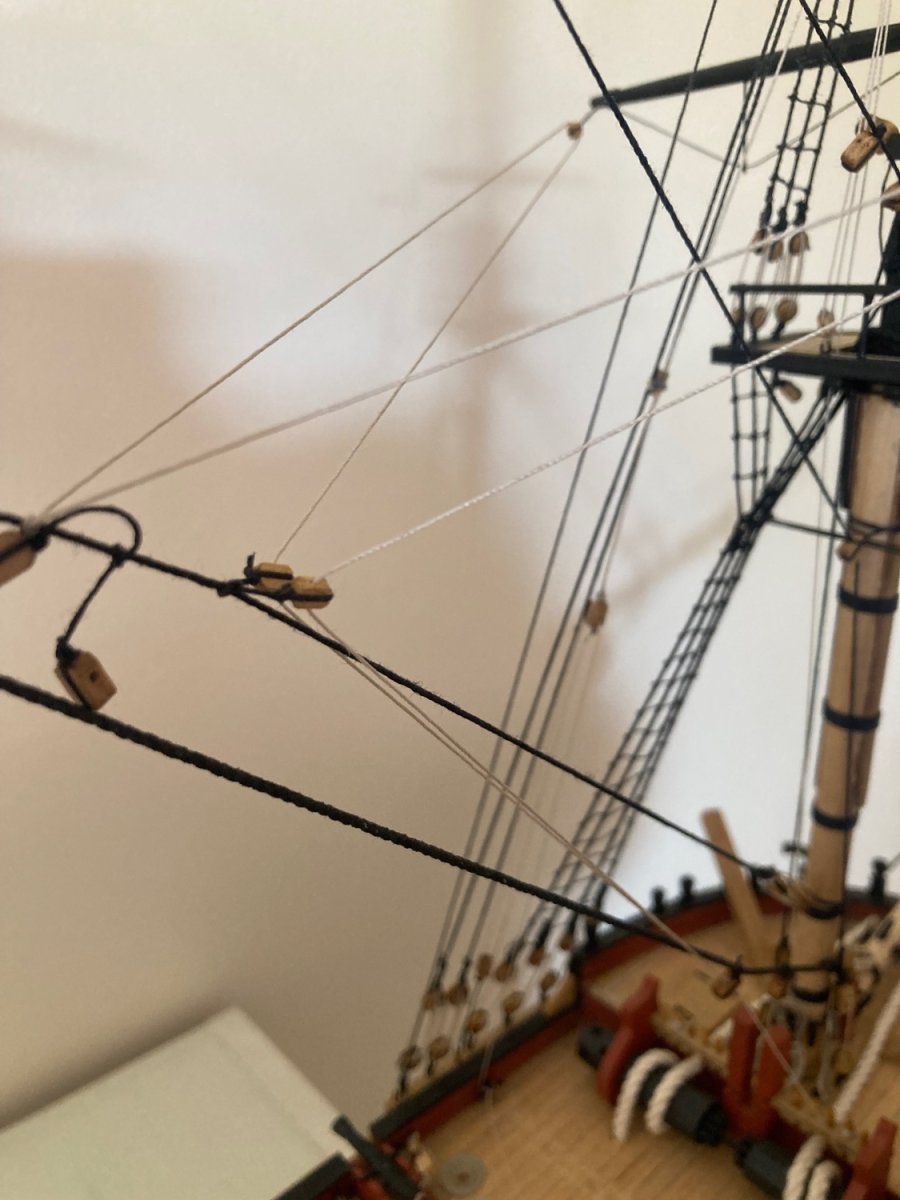
Because there’s virtually no weight to the driver-gaff, its running rigging appeared too loose. So I’ve added two extra ropes down to the quarterdeck to keep it under tension. They’re not in the plans but they don’t look too out of place. (I hope.) The three blocks for the gaff’s tackle are supposed to be all mounted behind the main mast-head. The rope’s run down the mast would be fowled by the the top, so I relocated the lowest block to the rear of the top. I made it a double block to accommodate both the upper and lower gaff’s tackle in the same manner.
-
I’ve attached the gaff-booms before I rig the main shrouds. Advice sought: The plans show the support rope for the driver gaff passing through three blocks at the rear of the main mast-head before dropping vertically down to be lashed on a cleat at the base of the mast. But the main-top’s in the way. Should the rope pass through the right-hand side lubber’s hole? (Where it will rub.) Or down behind the top? (Where it will rub.) or should I drill a small hole in the main-top behind the mast for the driver gaff rope to pass without impediment? (Edit) Solution: Duh…I’ll just move the lowest of the three blocks to sit at the rear edge of the main-top. Simple. Sometimes you have to hit the “submit” button before nutting it out.
-
S t u n n i n g build, there, Jason. Very well done indeed. Congratulations.
- 800 replies
-
- 3
-

-

-
- snake
- caldercraft
- (and 1 more)
-
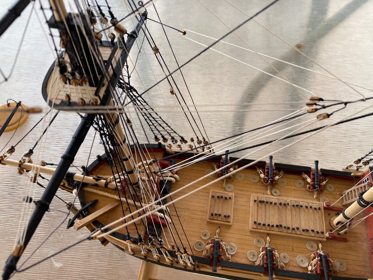
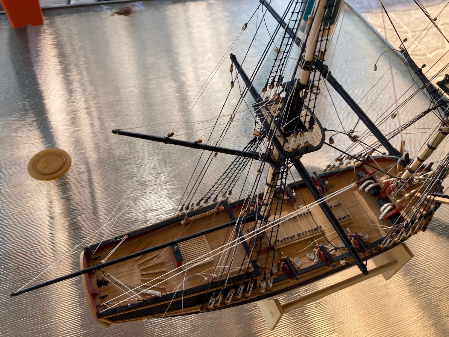
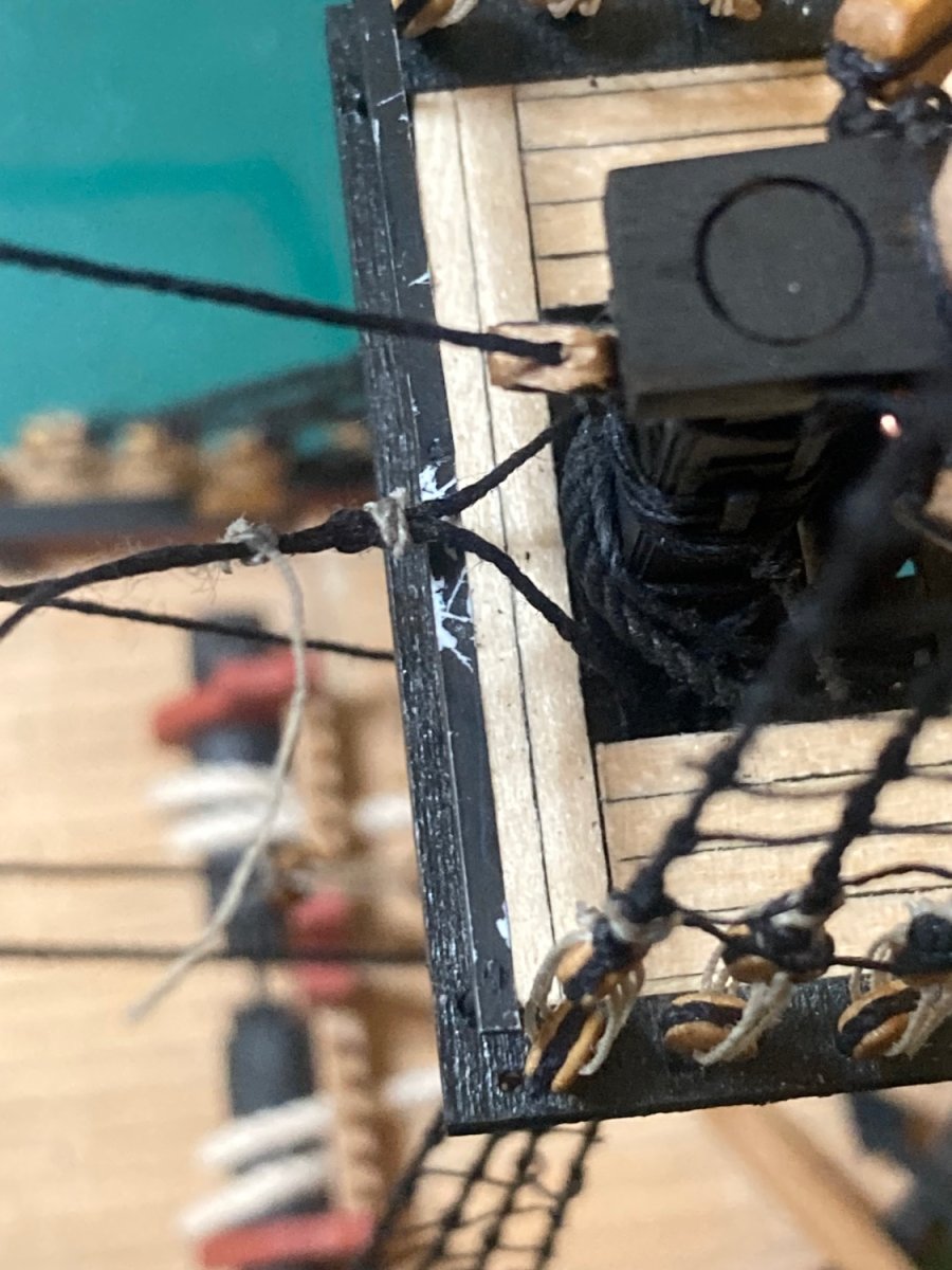
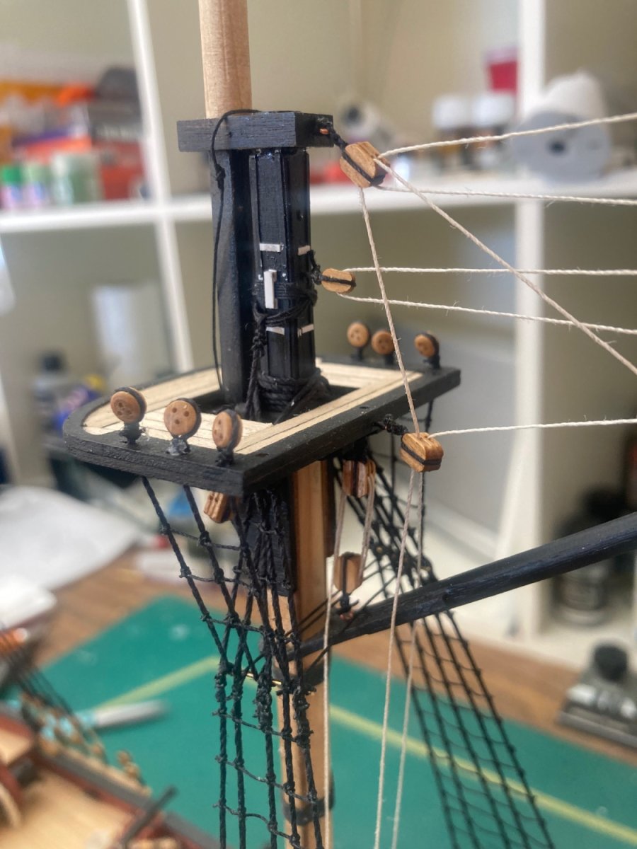
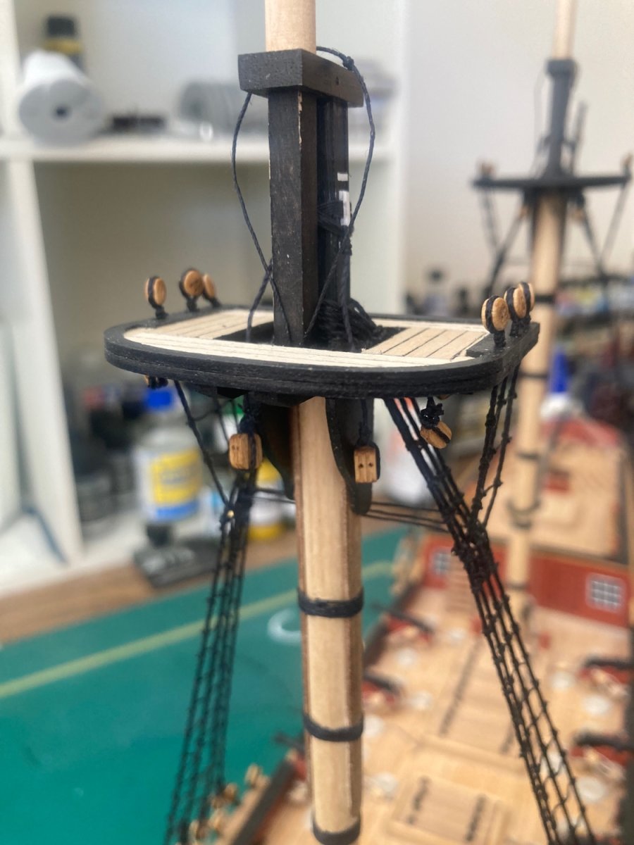
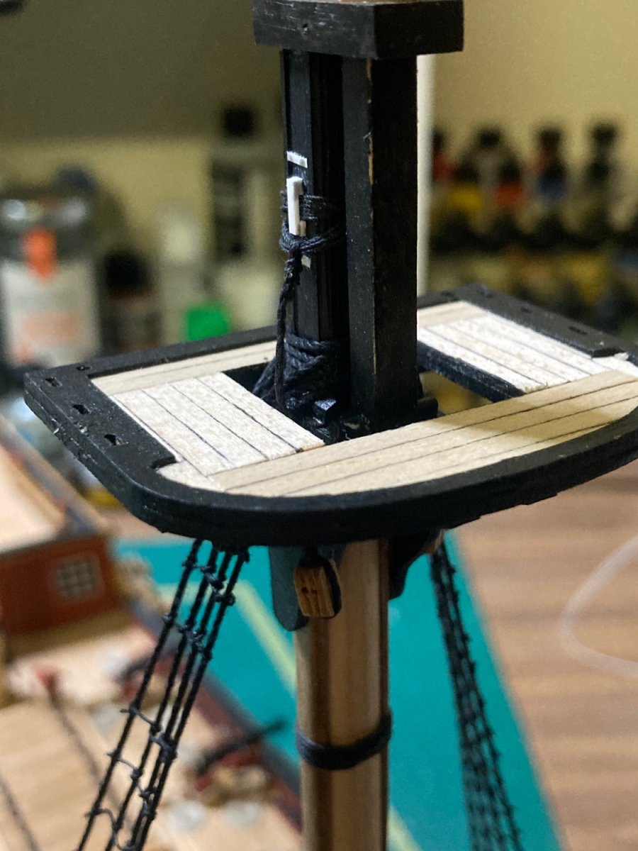
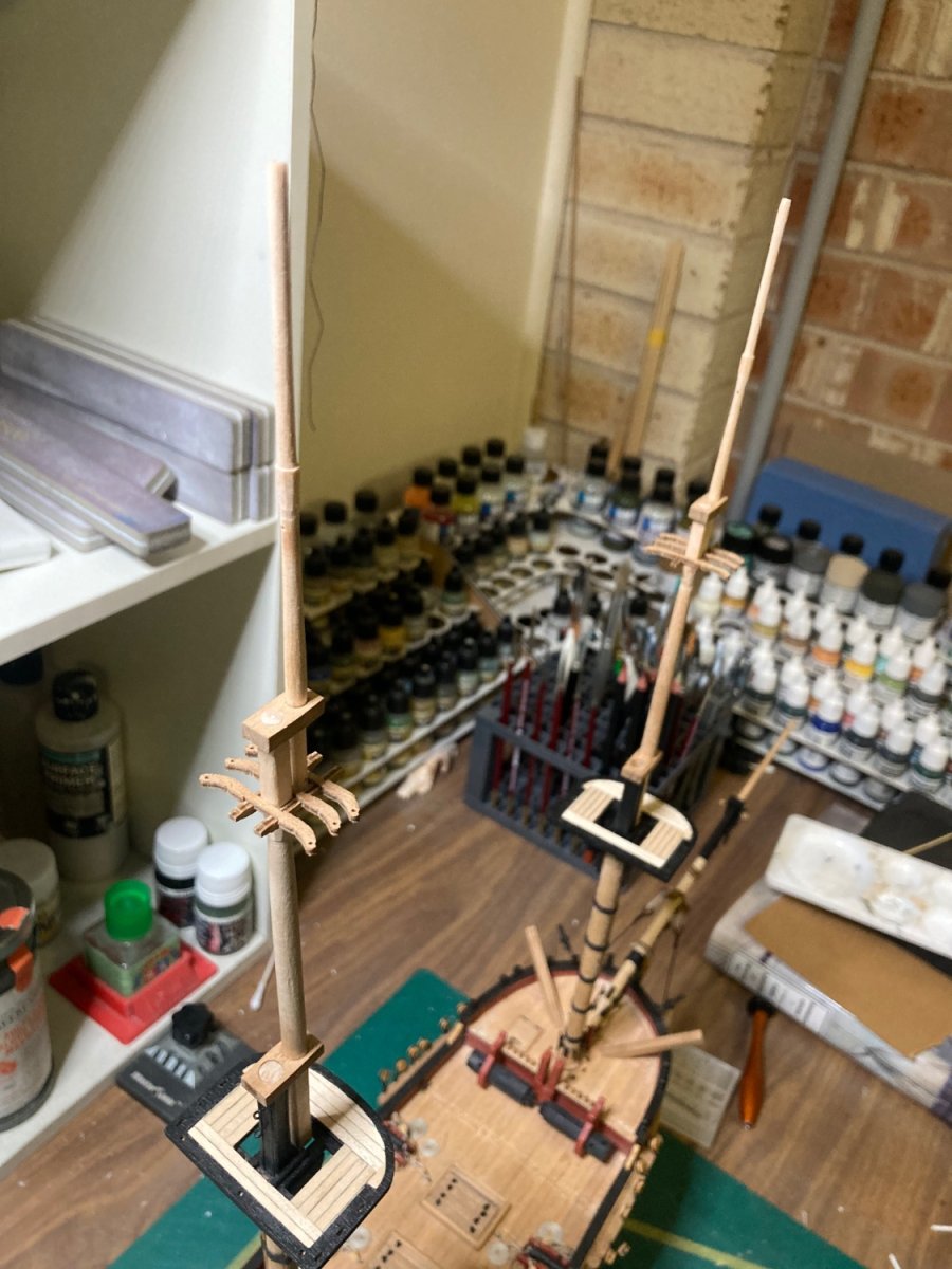
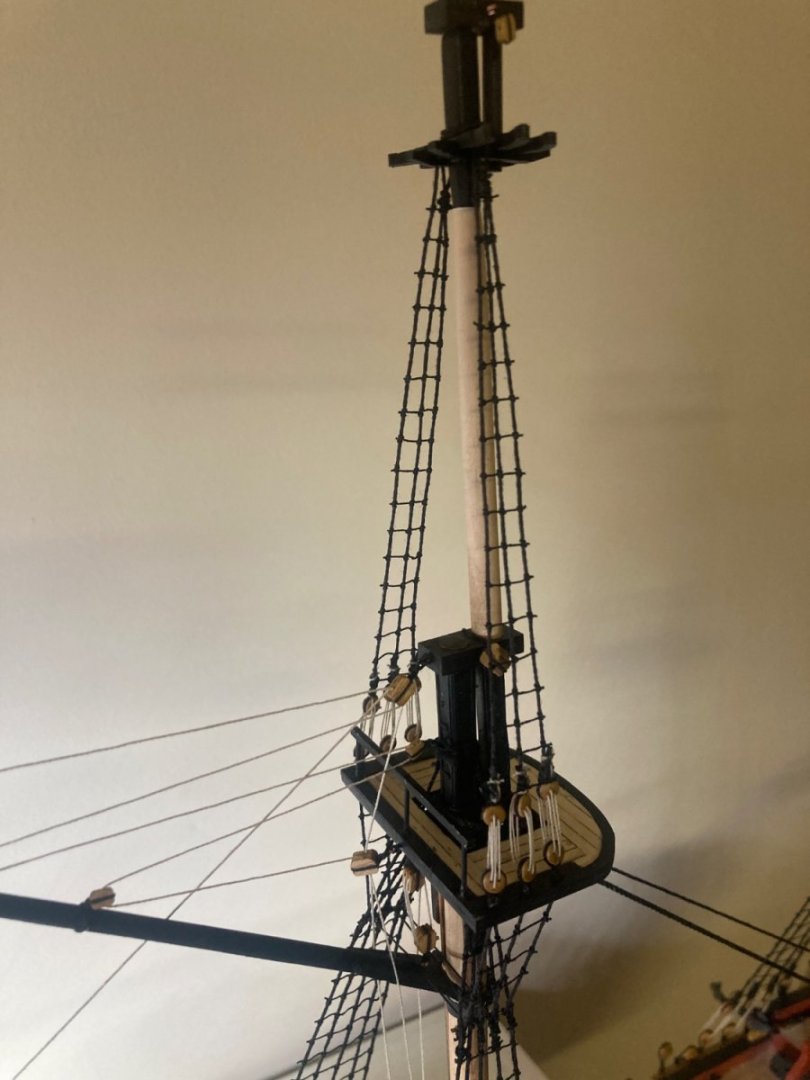
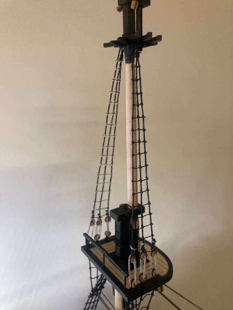
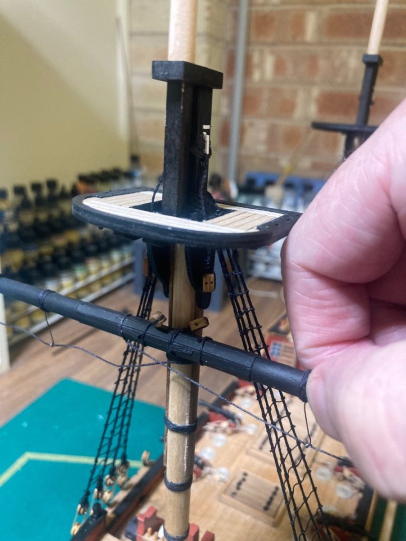
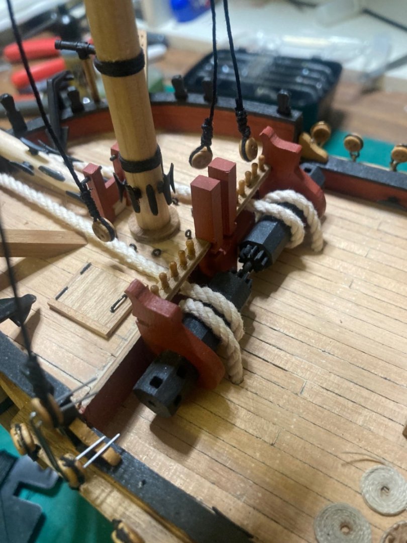
Caldercraft 1:64 HM Brig Supply. With the fore-mast’s lower shrouds and rat-lines completed, I’m thinking about how I’m going to suspend the fore-yard. Referencing a drawing from the book “The Anatomy Of Nelson’s Ships”, I’m trying to improve on the kit’s accuracy. But I’ll simplify it a fair bit because it’s not the Victory… So I made elm-cleats out of Evergreen styrene and glued them to the fore and main-top. I left them open at the top end. Then I wound 0.5mm thread around the tops using 2mm rod as a spacer, then dropped them into the open cleat before closing its top off. Rinse and repeat three more times. (I’ll paint the styrene black later.) From these rope coils hang the jeer-strops: Thicker rope to which the jeer-blocks are attached at the bottom. These pass through the lubber’s hole. Rope around the yards pass through the block’s pulleys and take the weight of the lower masts. The ropes will be lashed to the deck and tied off by the cleats around the base of the masts.


-
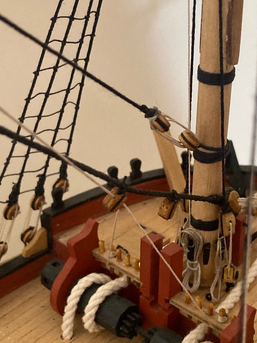
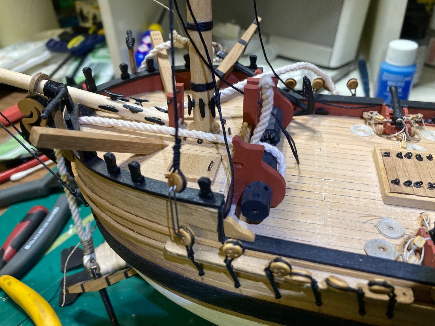
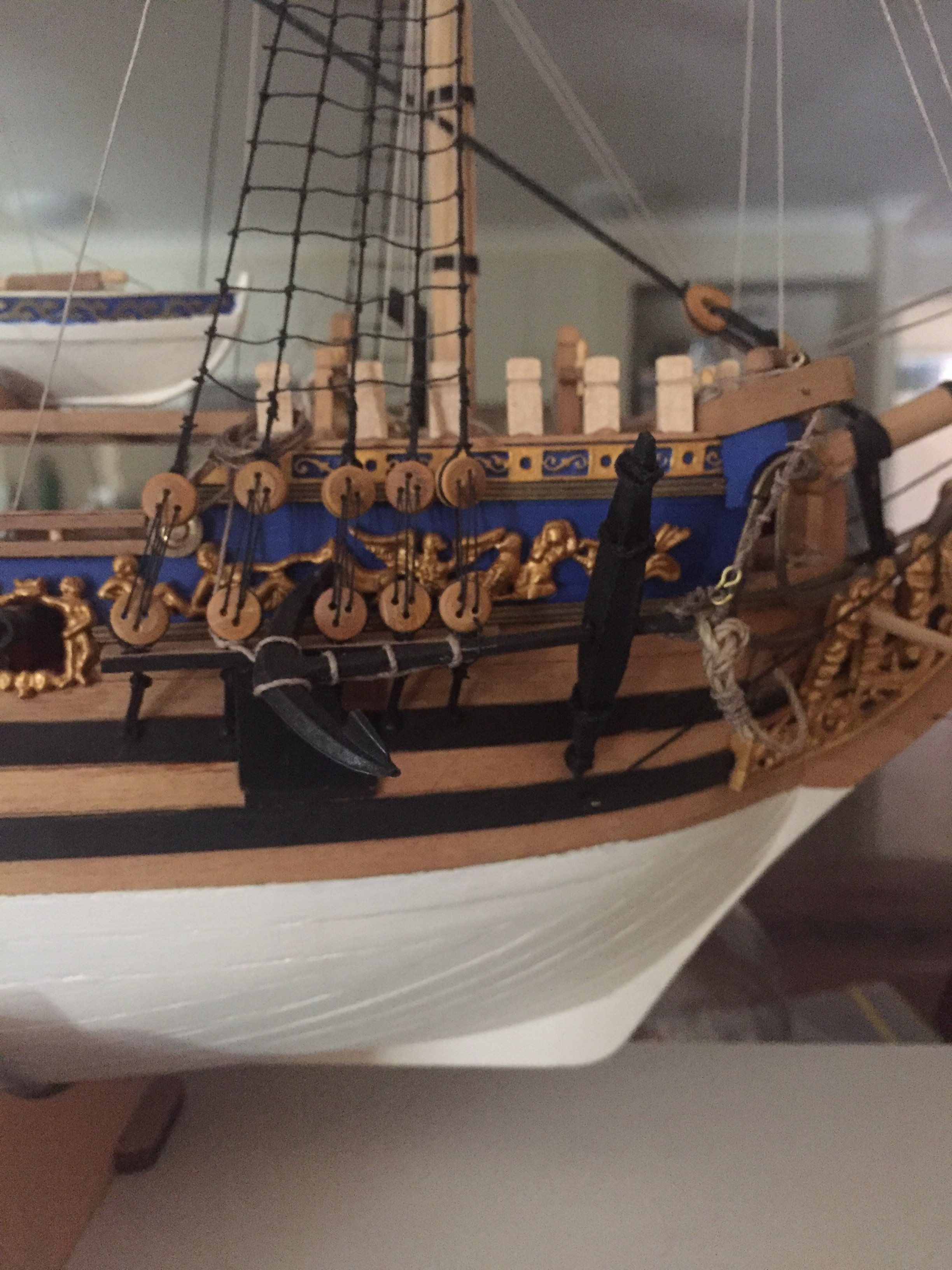
My anchor cable solution. I’m not overly impressed by the length provided. An extra 20cm wouldn’t have bankrupted JoTiKa…. But here we are. The front four shroud deadeyes have been rigged to length. I’m calling it a night.
-
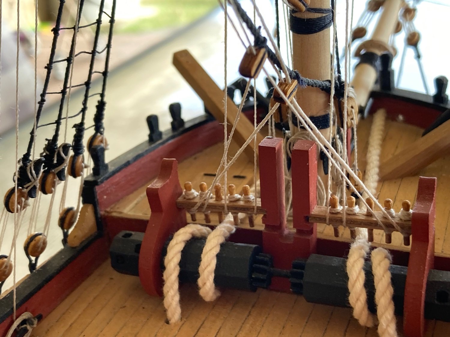
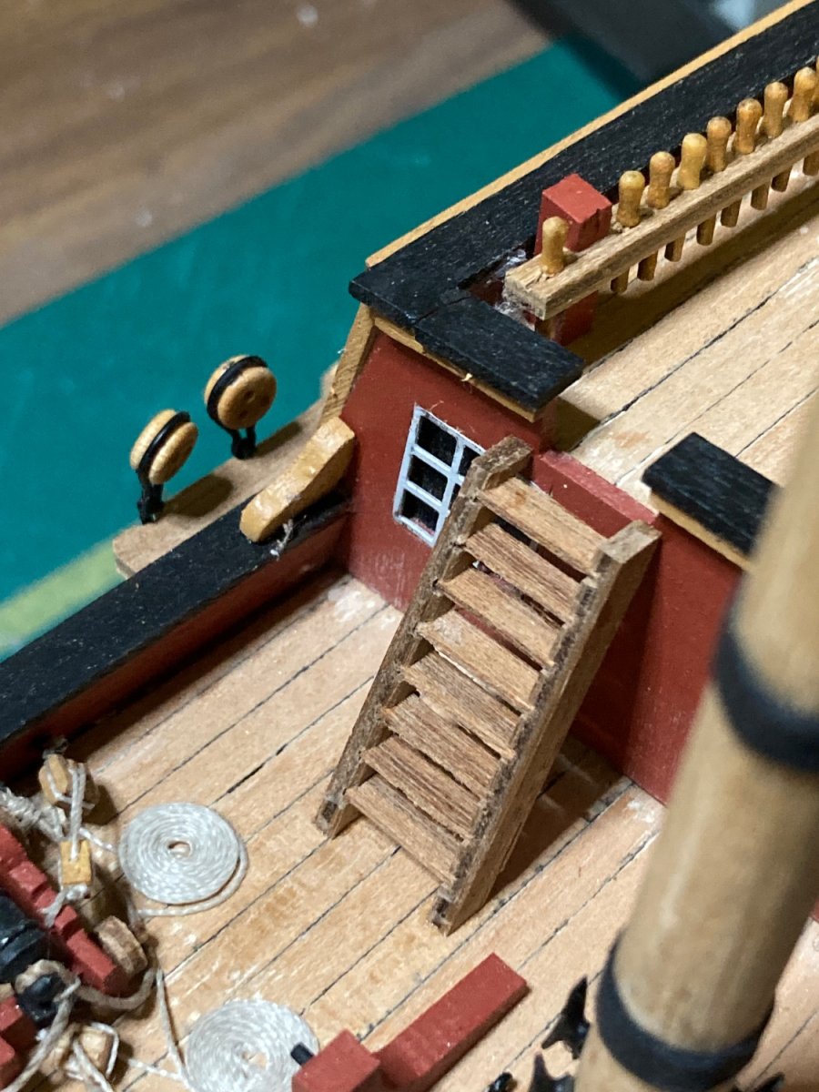
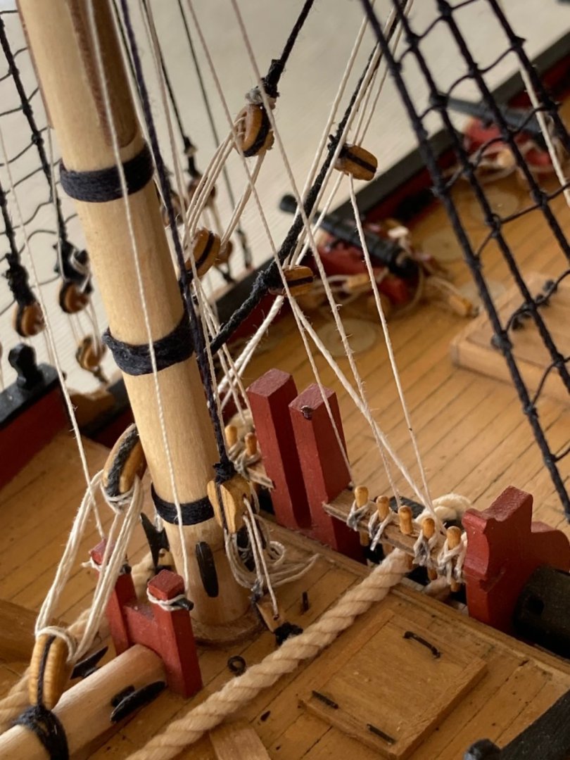
I was planning on wrapping the anchor cables twice around the winch, then through the main deck’s forward hatch, but only 500mm of 2.5mm natural hemp is supplied for the anchor cable. So I’ve had to simplify the anchor cable’s routing method. A clove-hitch at both ends of the cable to prevent unravelling, then two in the centre with a cut in between. 2x 250mm lengths per anchor. A simple bight at the anchor’s ring that’s been west-country whipped, then only once around the winch. I’ll drill two holes through the deck behind the winch and push the cables through. Shrouds; The plans recommend a piece of wire with two 90° bends 15mm apart be used to space the deadeyes apart before lashing them. So…yep. That happened. More west-country whipping. (Ten years of being a Scout leader has paid off.) The quarterdeck ladder’s been mounted: the last of the deck fittings. Huzzah!


-
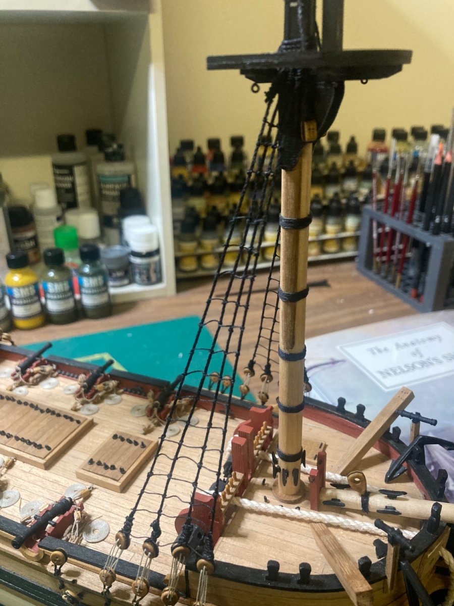
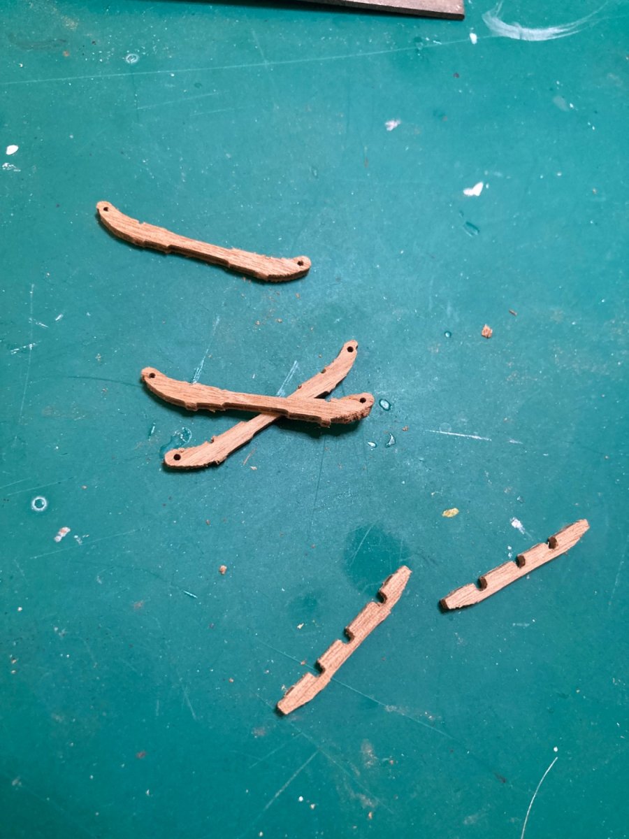
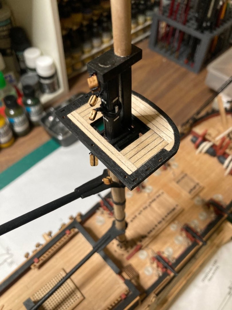
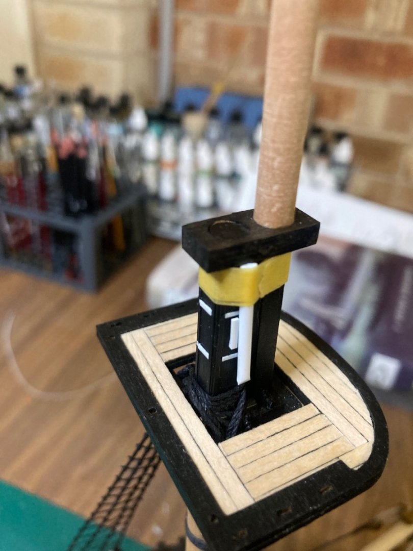
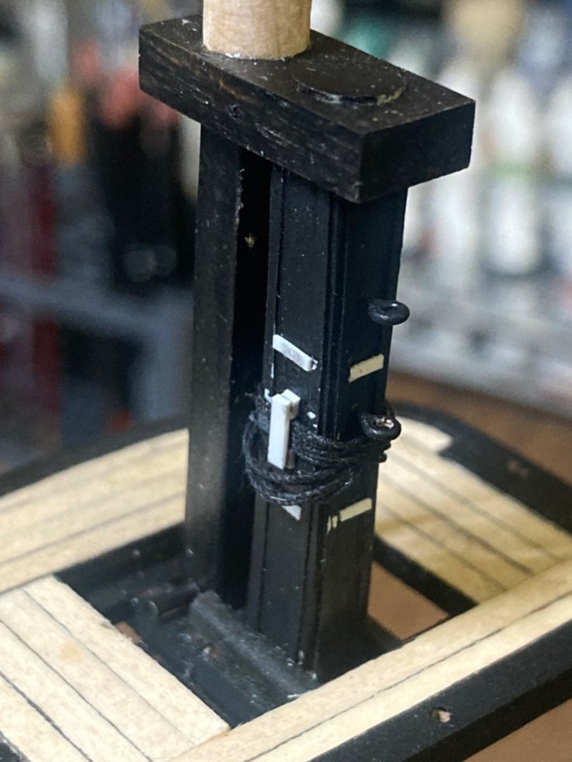
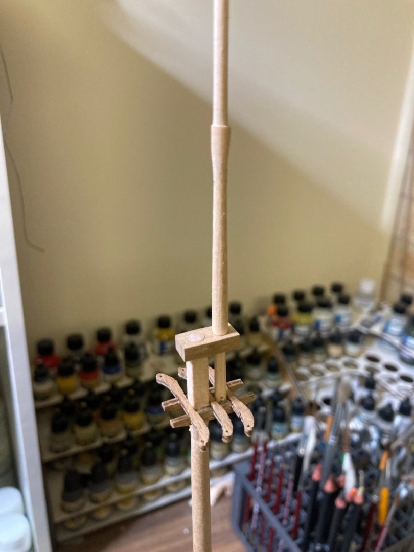
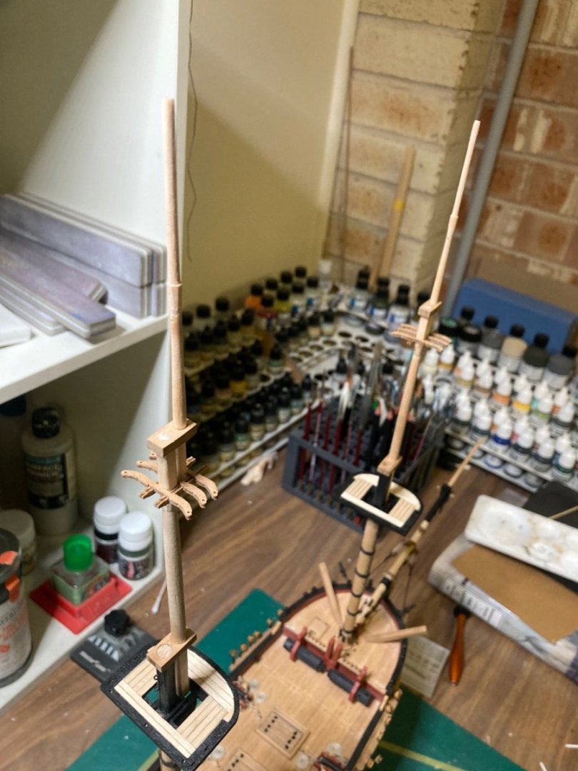
The chesstrees and crosstrees were cut out of the parts frame. I took the opportunity to remove the last two remaining kit parts from the frames: The ladder sides for the quarterdeck. After a bit of work, the trees were fitted near the topmast’s uppers, resting on the “hounds”; the point where the mast changes from an octagonal taper to a smaller diameter square. The topgallant masts rest on the chesstrees with a fid in the same way the topmasts rest on the mast’s tops further down. I’m really enjoying myself. It’s been too long.

-
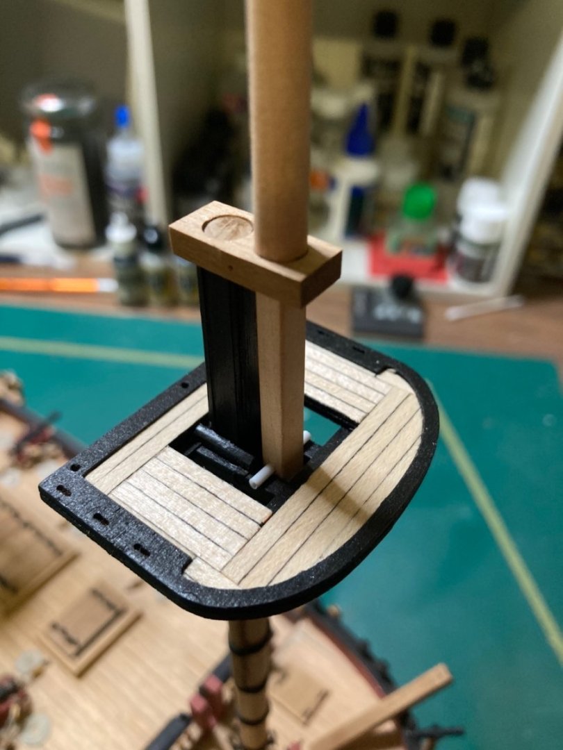
The fore and main topmasts have now been drilled through at the bottom. The beam that supports their weight (the fid) is pushed through once the mast has been lowered through the lower mast’s caps.
-
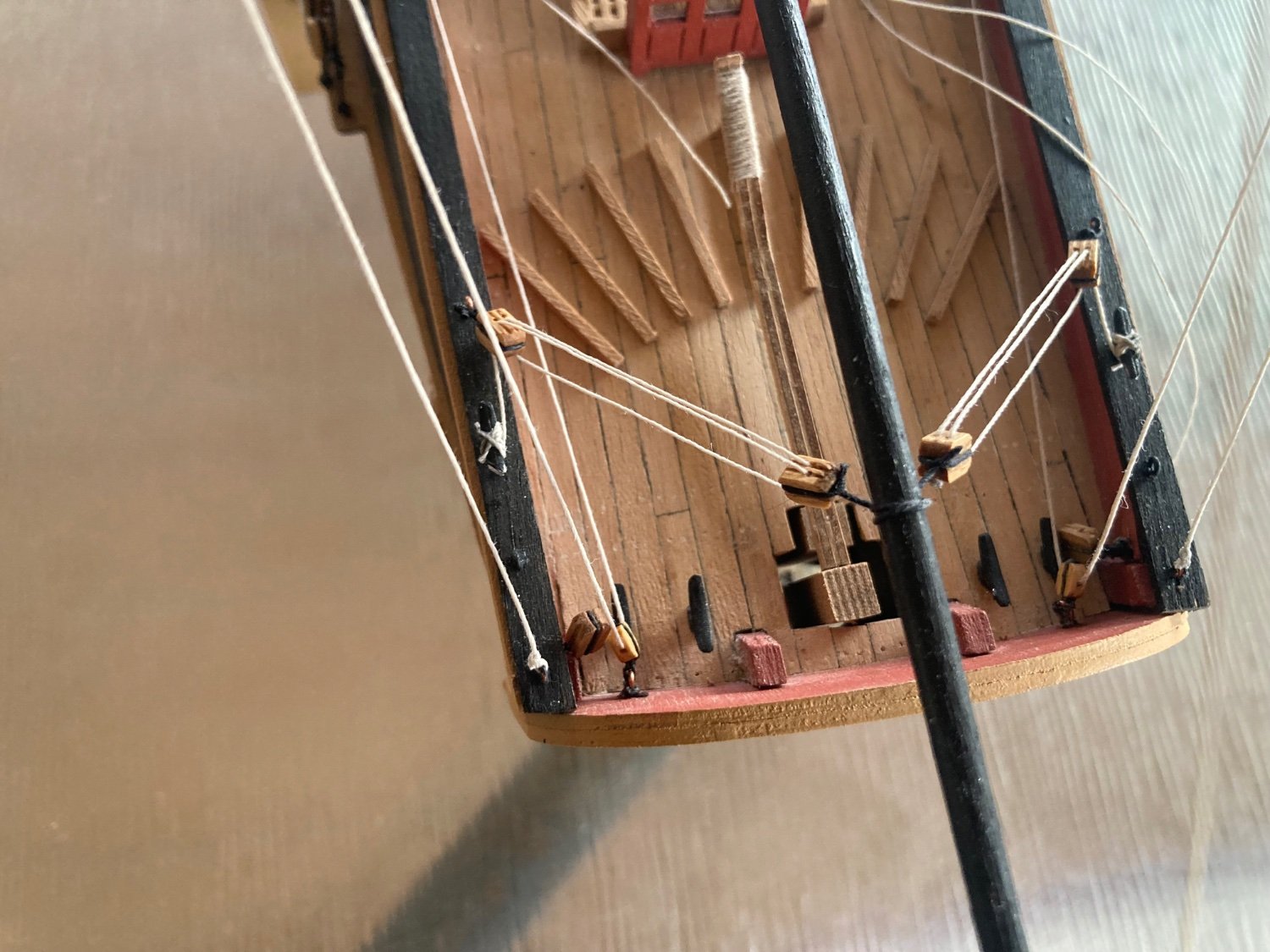
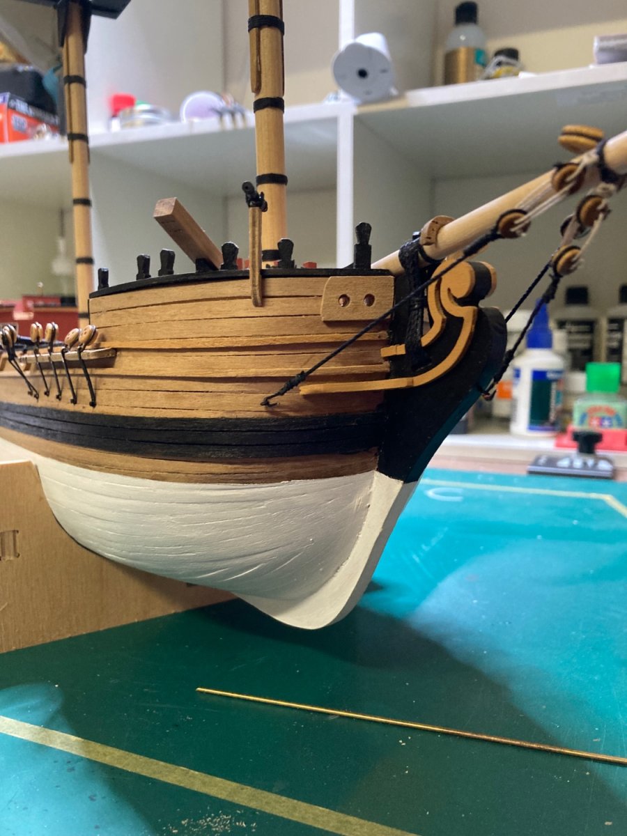
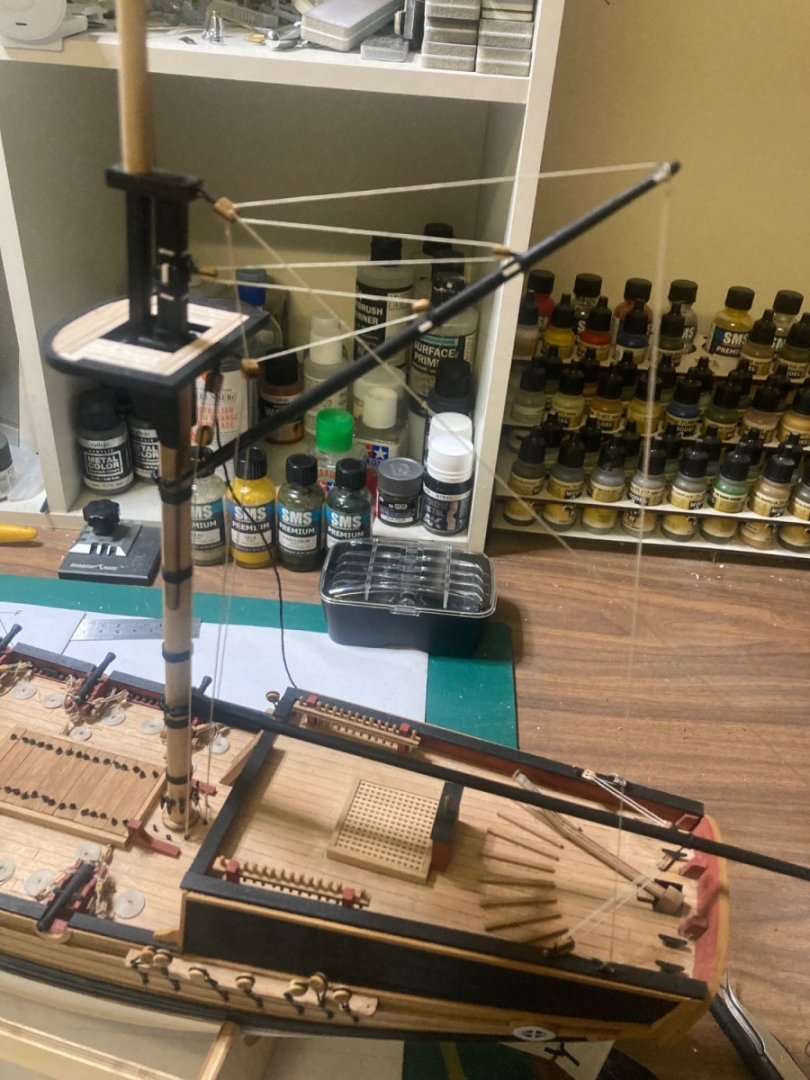
The bowsprit’s now mounted, gammoned and three stays have been rigged with eyelets, hooks and deadeyes.


-
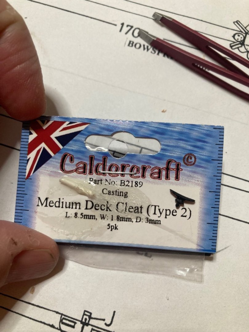
Well, after Caldercraft advised me they were going to send me the 5x missing deck cleats, I waited three months. Nothing arrived. I re-sent the email, asking if they were in the mail. My email enquiry received no response. So I just bought some from my local supplier. AU$2.95. My wife tells me I should have just bought them months ago. Yep. So… Five months later… I finally have the parts I need. Time to progress the build.
-
I’ve had a response from Caldercraft regarding the errors in the plans: ”I have now had a chance to look through the information that you provided and, as you say, there are a couple of human errors on the plans/parts list which we have now corrected with your assistance. Errors 1 and 2, with regard to the incorrect part number (#137 should be #138) on plan sheet 2 has now been corrected and positioning of part #137, previously missing, has now also been added to all plans. Error 3, the incorrect quantity of cleats, #85, being provided/shown on the plan sheets has now been corrected. We are always grateful to customers reaching out to us with potential errors in order to put things right; with the greatest will in the world, it doesn’t matter how many times we proof read and check over plans/manuals something always gets through! Despite the kit of Supply being on sale for many years, from the serial number it appears your kit was manufactured in 2014, to my knowledge this is the first time these issues have ever been raised. We are more than happy to send you the 5 additional cleats in order to allow the kit to be completed as intended.” Very pleased with their response.