KurtH
-
Posts
425 -
Joined
-
Last visited
1 Follower

-
 KurtH reacted to a post in a topic:
Christiania 1774 by TJM – approx. 1:67-1:64 – Danish Light Frigate based on Vanguard Models HMS Sphinx
KurtH reacted to a post in a topic:
Christiania 1774 by TJM – approx. 1:67-1:64 – Danish Light Frigate based on Vanguard Models HMS Sphinx
-
KurtH reacted to a post in a topic:
Lancha Chilota by JacquesCousteau – Scale 1:32 – Chilean Coasting Sloop
-
KurtH reacted to a post in a topic:
USS Constitution by threebs - BlueJacket Shipcrafters - 1/8" scale
-
KurtH reacted to a post in a topic:
USS Constitution by g8rfan99 - BlueJacket Shipcrafters - 1/98
-
KurtH reacted to a post in a topic:
Lancha Chilota by JacquesCousteau – Scale 1:32 – Chilean Coasting Sloop
-
KurtH reacted to a post in a topic:
Lancha Chilota by JacquesCousteau – Scale 1:32 – Chilean Coasting Sloop
-
KurtH reacted to a post in a topic:
USS Constitution by g8rfan99 - BlueJacket Shipcrafters - 1/98
-
KurtH reacted to a post in a topic:
Lancha Chilota by JacquesCousteau – Scale 1:32 – Chilean Coasting Sloop
-
KurtH reacted to a post in a topic:
Red Jacket by John Ruy - Marine Model Company - 1/16”=1’ (1/192 scale) - Vintage Solid Hull Clipper Ship Kit
-
KurtH reacted to a post in a topic:
Pinas by rcweir - Kolderstok - Scale 1:50 - Cross-Section - Dutch 17th Century ship
-
Wow!! What a great job you have done with the bowheads! Yours is the only bowheads with this configuration I have seen on any wooden model build other than the one by Herb Ebson a photo of which which I posted above. Congrats!!
-
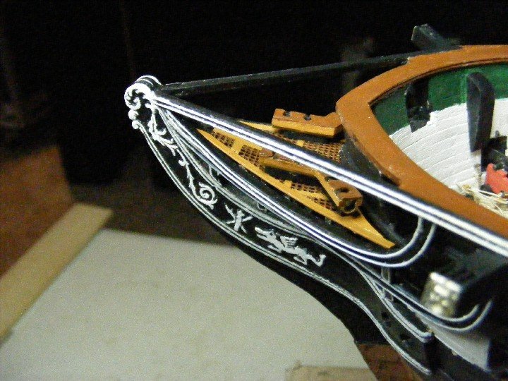
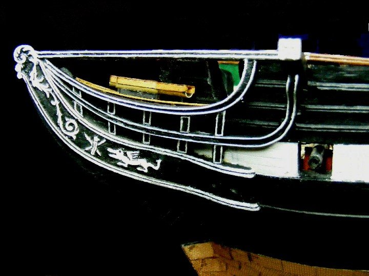
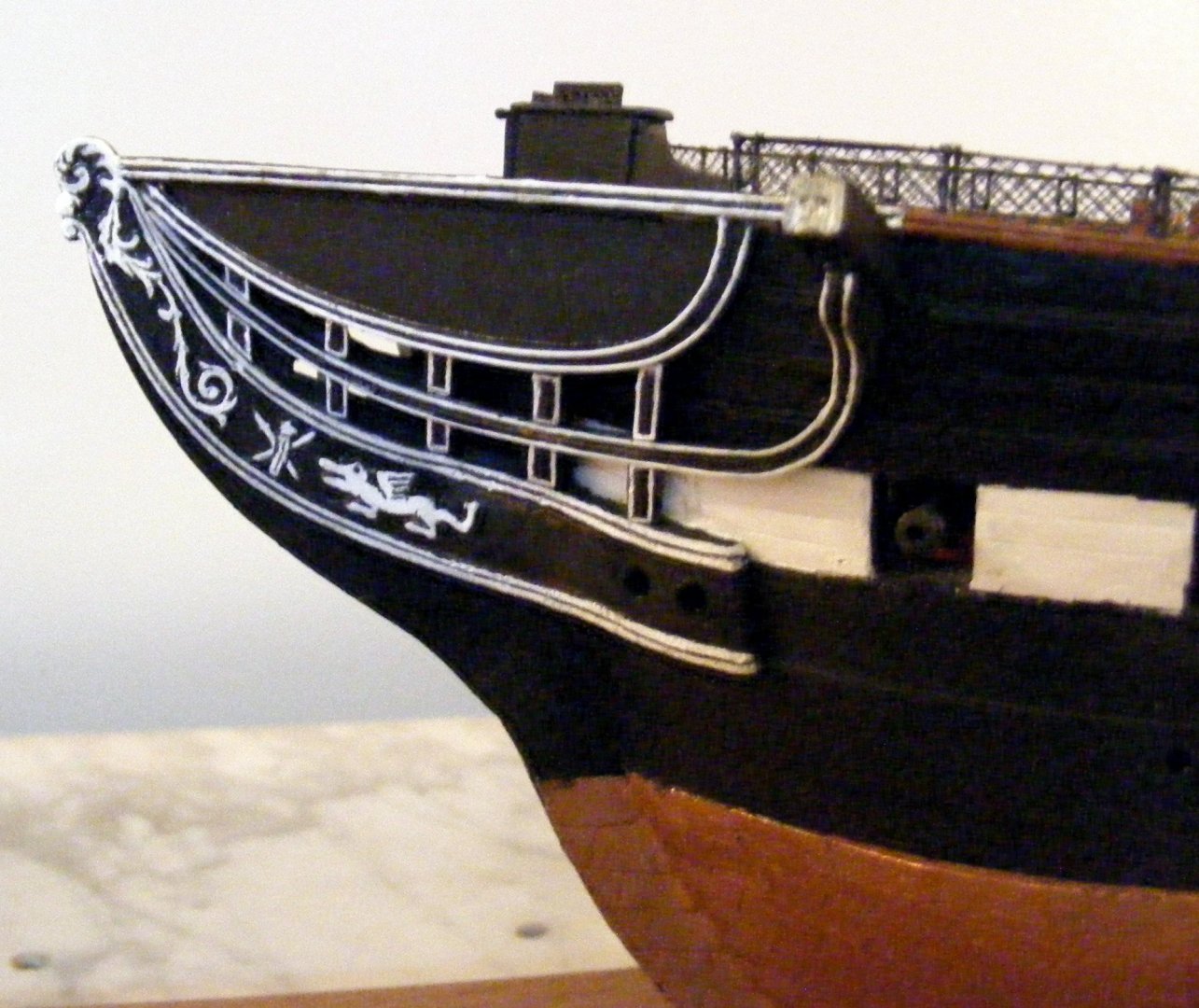
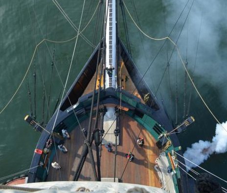
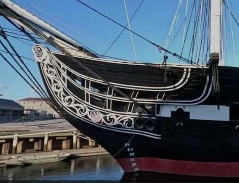
First, some definitions. The straight rail which extends from the cap rail to the billet head is what I call the false rail. The rail below that is what I call the main rail. The lowest one that curves upward to become the cathead knee is what I call the second rail. Looking straight down on the bow of the carved hull provided in the kit, you can see that it is semicircular. The provided PE grating is designed to fit this profile. You can see in this photo of the actual ship that this design is wrong: Accordingly, I altered the profile of the bow when I did the hull shaping. It looks like you did the same. Consequently I made major changes to the PE piece narrowing it quite a lot and adding Britannia metal strips on each side to replace the framing that I cut away: I did not cut any additional notches out of the center. I believe that it sits on top of the stem, but I cannot remember for sure. As you can see, I had to shorten the seats of ease so that they would fit into the reduced space. My intention was that the grating would curve to match the curve of the main rail. As you can see, it sits slightly above the rail. This defect was fortunately masked when I installed the carboard (canvas) covering: The bowsprit sits a millimeter or so above the grating on my model, but I see no reason not to have it sit on the grating. However, since the angle of the bowsprit is different than the grating the only contact would be at the aft edge of the grating.
-
Sorry to be so late in answering your question. I used the clunky Britannia Metal cast trailboard. I did not have to remove wood from the stem knee to get a good fit at the end, but I regretted not having tapered the stem knee to a point before gluing them on. I did encounter a host of other similar problems throughout the build. It seemed that I was constantly fettlin things in order to make everything fit. E, g, the main fife rail assembly was a nightmare. Being inexperienced at building from wooden kits, I just thought that it was part of the process.
-
rcweir reacted to a post in a topic:
HMS Sphinx by KurtH - Vanguard Models - 1/64 - First POB Model
-
brunnels reacted to a post in a topic:
HMS Sphinx by KurtH - Vanguard Models - 1/64 - First POB Model
-
Knocklouder reacted to a post in a topic:
HMS Sphinx by KurtH - Vanguard Models - 1/64 - First POB Model
-
Thukydides reacted to a post in a topic:
HMS Sphinx by KurtH - Vanguard Models - 1/64 - First POB Model
-
SaltyScot reacted to a post in a topic:
HMS Sphinx by KurtH - Vanguard Models - 1/64 - First POB Model
-
My BJ kit did supply a Britannia metal cast of the Lion face. However, it is square rather than rectangular as is the current sculpture
-
ccoyle reacted to a post in a topic:
HMS Sphinx by KurtH - Vanguard Models - 1/64 - First POB Model
-
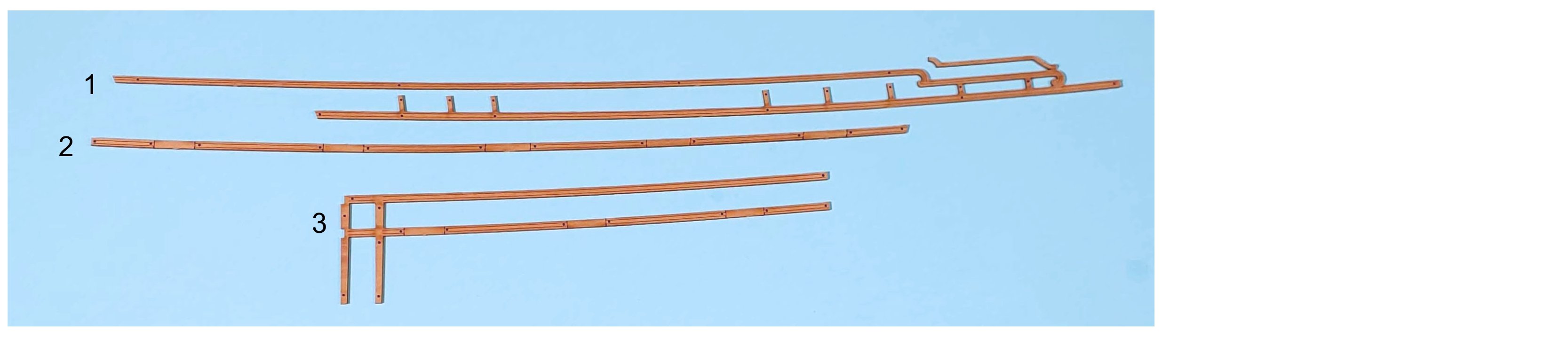
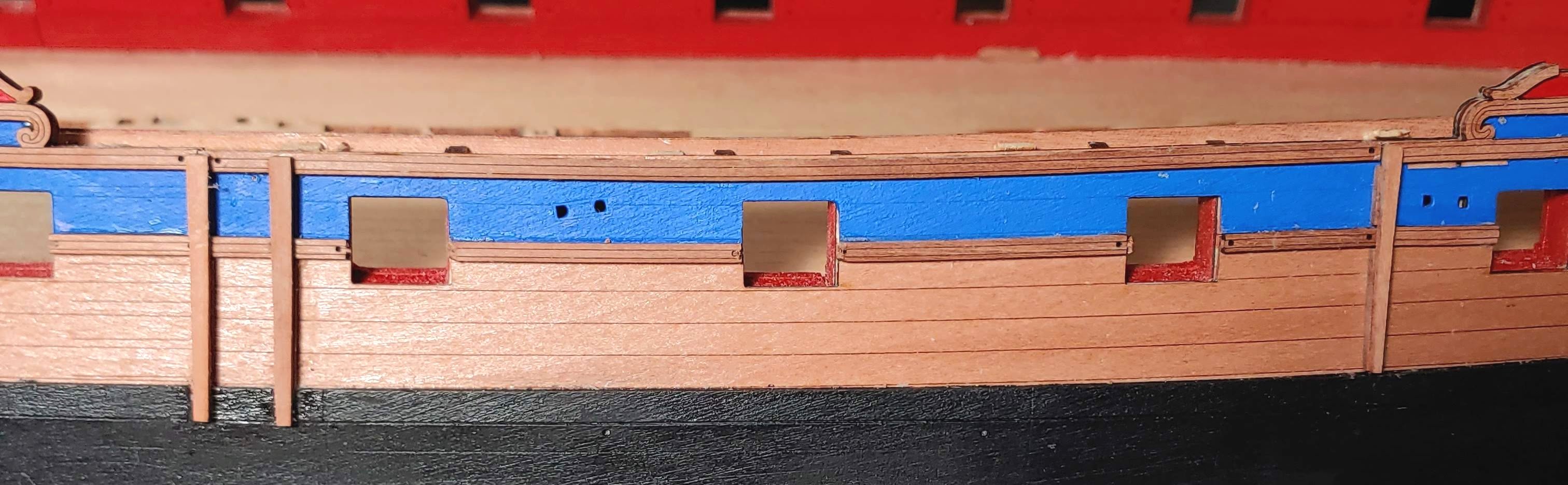
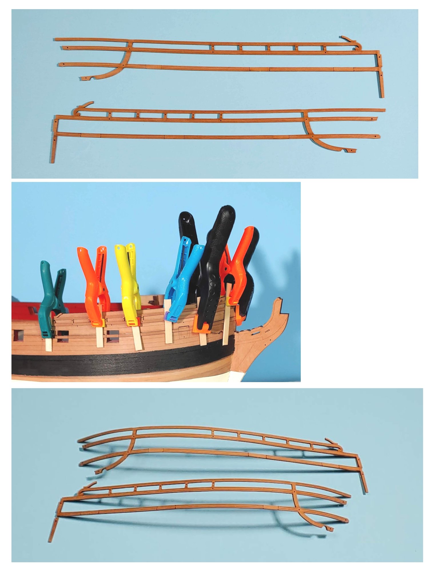
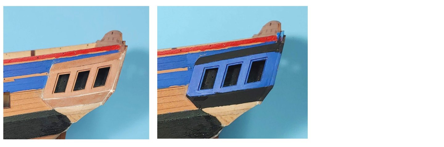
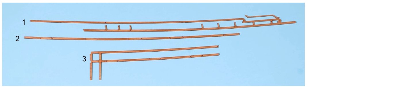
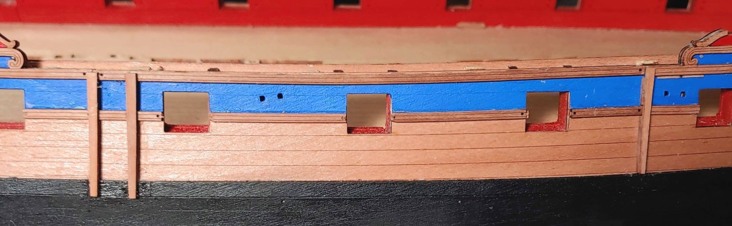
Quarter gallery filled then painted: Rail patterns: 1. Sheer rail pattern 2. Waist rail pattern 3. Sheer and waist rail pattern The pin holes provided in the rails and in the hull were critical in being able to place the rails in place quickly and accurately before the glue set. Rail patterns installed: Side fender patterns (left), and chess tree patterns (right) Fender and chess tree patterns installed: Current state of play: It is time for me to step away from this build in order to do my yearly video job. I expect to resume work late in July.


-
 catopower reacted to a post in a topic:
USS Constitution by KurtH - FINISHED - BlueJacket Shipcrafters - 1/96 - First wood model kit
catopower reacted to a post in a topic:
USS Constitution by KurtH - FINISHED - BlueJacket Shipcrafters - 1/96 - First wood model kit
-
catopower reacted to a post in a topic:
USS Constitution by KurtH - FINISHED - BlueJacket Shipcrafters - 1/96 - First wood model kit
-
catopower reacted to a post in a topic:
USS Constitution by KurtH - FINISHED - BlueJacket Shipcrafters - 1/96 - First wood model kit
-
Unegawahya reacted to a post in a topic:
USS Constitution by KurtH - FINISHED - BlueJacket Shipcrafters - 1/96 - First wood model kit
-
Check to see of the stem and stern post align. I neglected to do that and paid the price later
-
Thanks Ron! Your work on the quarter galleries is really amazing!!
-
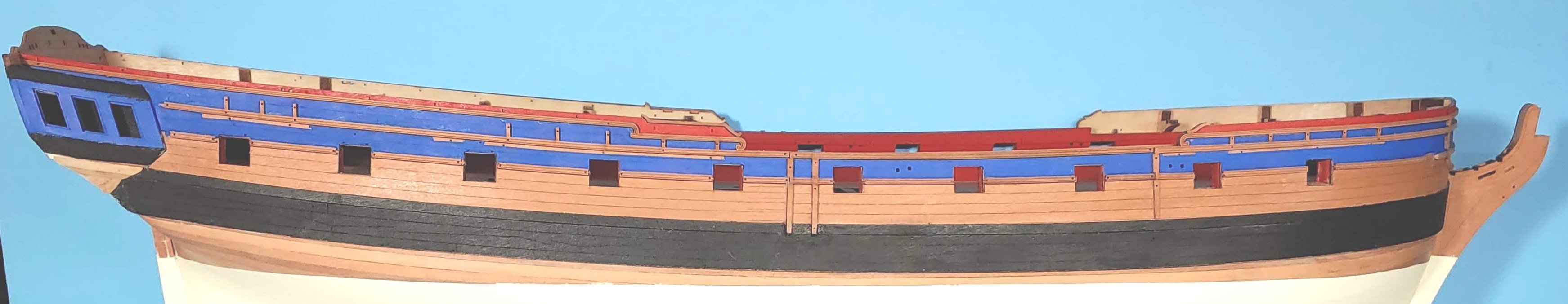
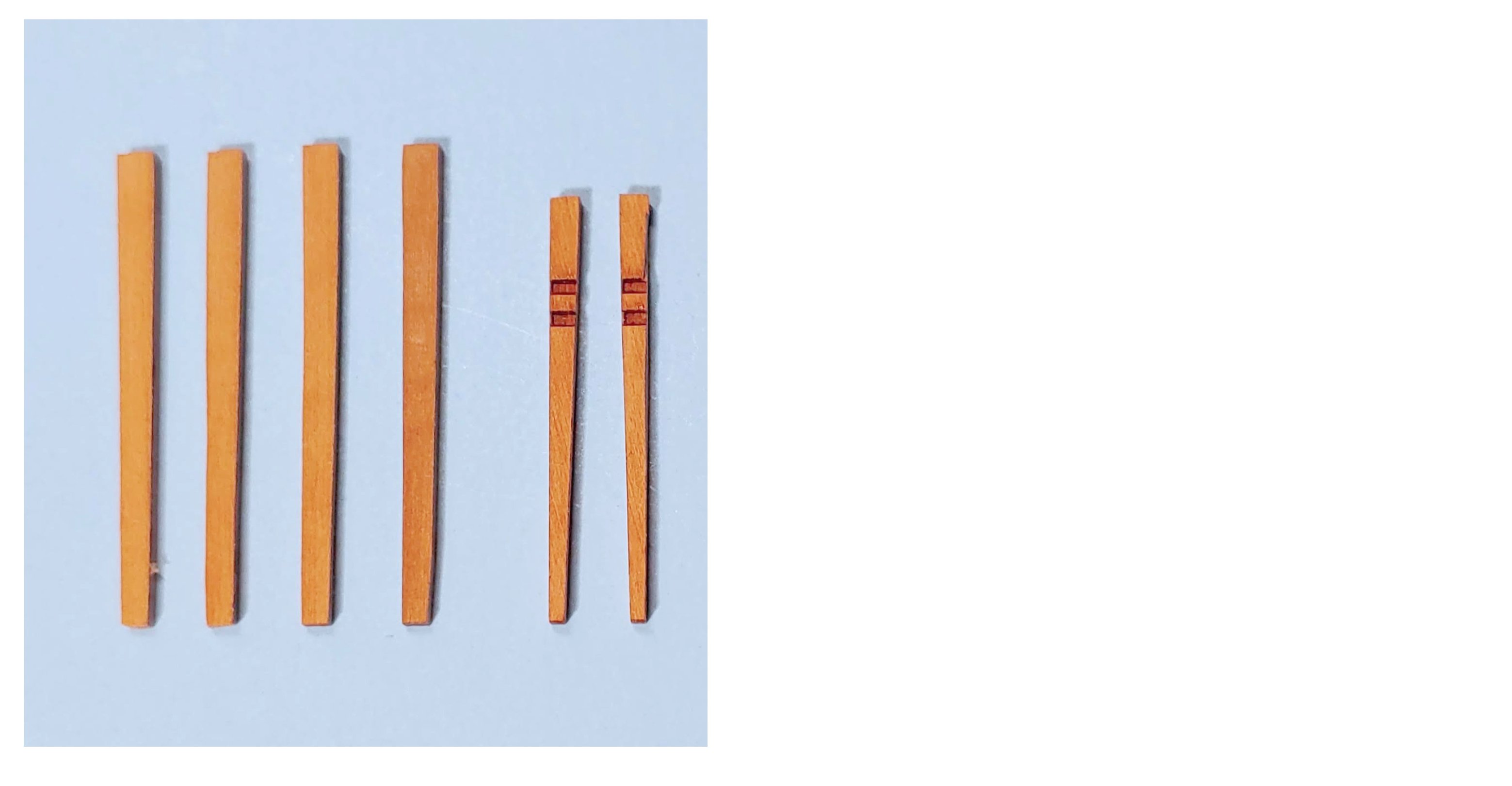
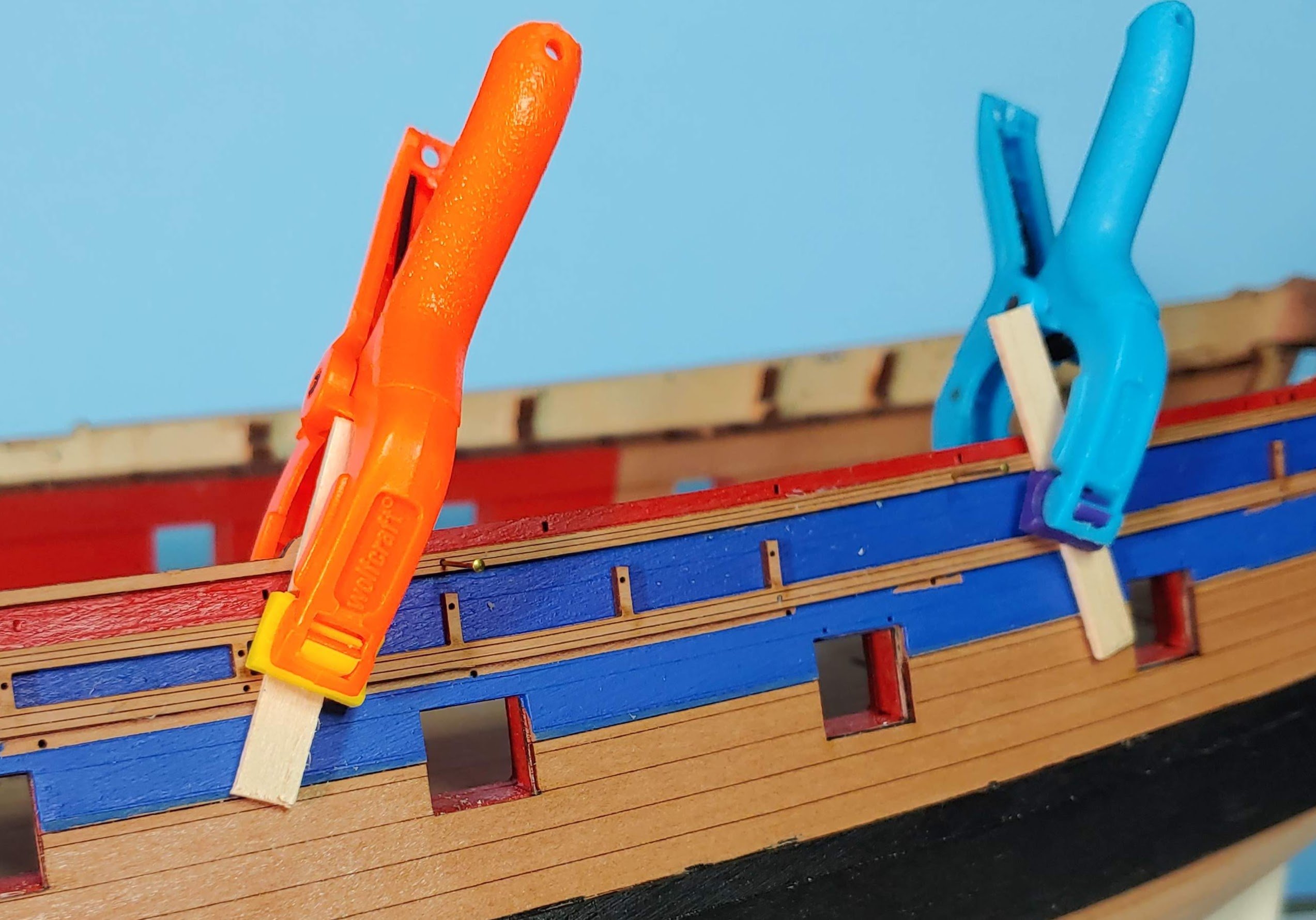
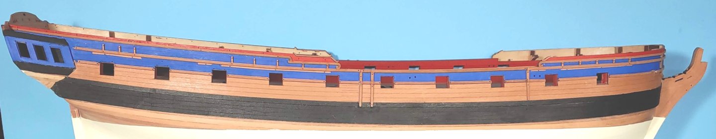
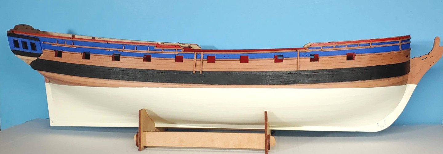
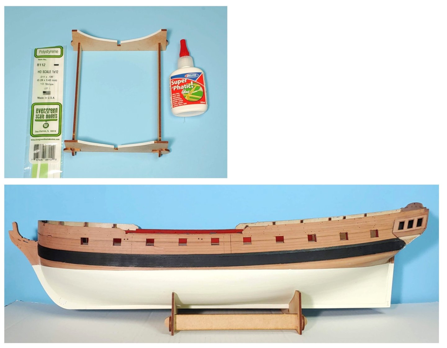
Modification of the cradle to prevent marking up the ship's bottom. Ship unmasked and set on the cradle: Preparation of the forward rails: I have painted the hull in preparation for the rail installation. The colors are Tamiya Flat Red (Same as the interior), and Vallejo Royal Blue. Since I plan to use Vallejo Yellow Ochre for the decorations rather than Gold, I thought a deeper shade of blue would create a better contrast. Vallejo Matt Acrylic Varnish was used for the natural wood areas, and as a base for the paint. I am not sure that I can install the rails before going out of town for 2 weeks, so I thought I should post what I have now. I just realized that more filling needs to be done on the quarter galleries, so I am leaving them unpainted for now.


-
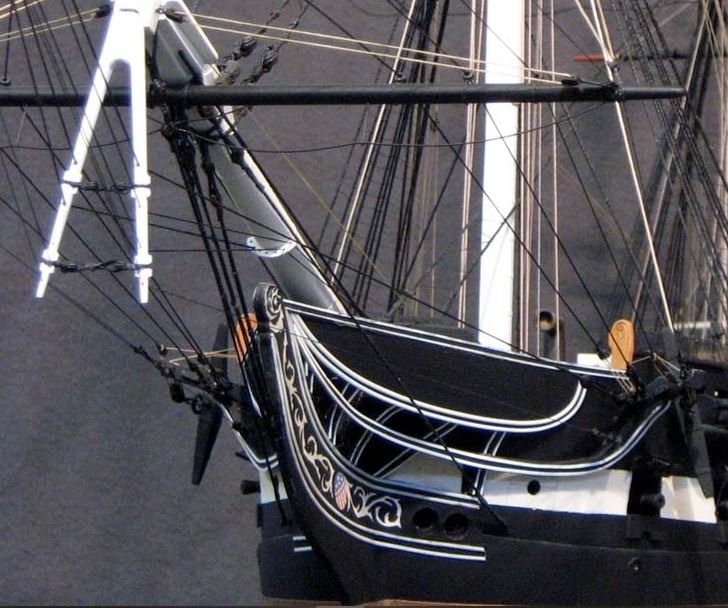
In a book of photos published in 1991 which I bought when I visited Constitution, foretack boomkins are in place. They look identical to those on the Hull model. I am guessing that since the courses were not set when they last sailed her, and likely will not be set if they sail her again, the boomkins will no longer be needed, hence their present absence.
-
Here is one: Hope this helps.
-
I have been unable to replicate the search that turned up those photos, but here is one more that I downloaded at that time.
-
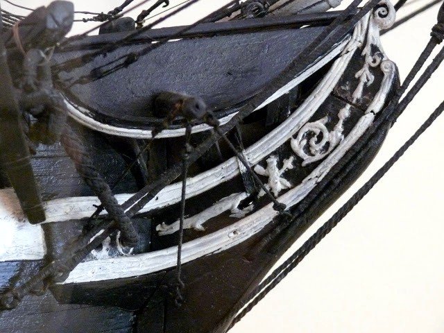
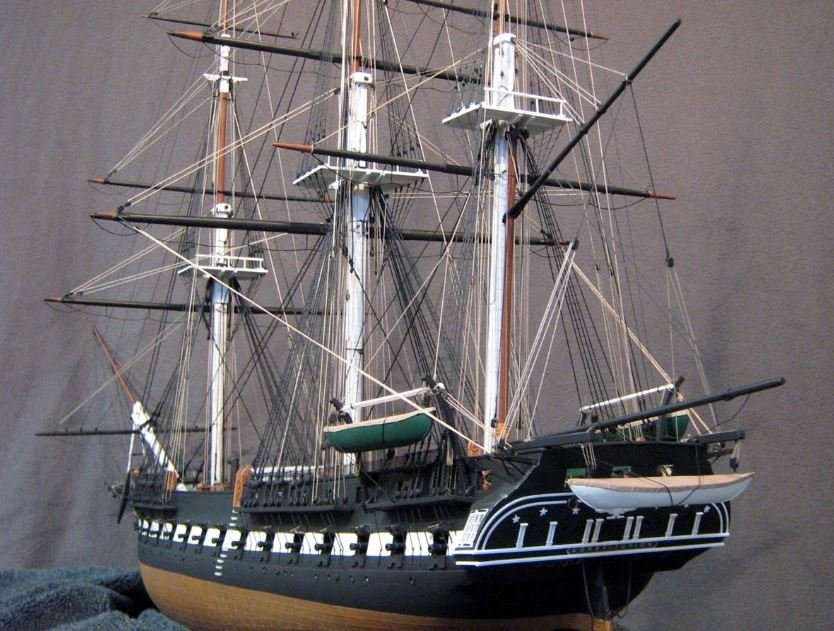
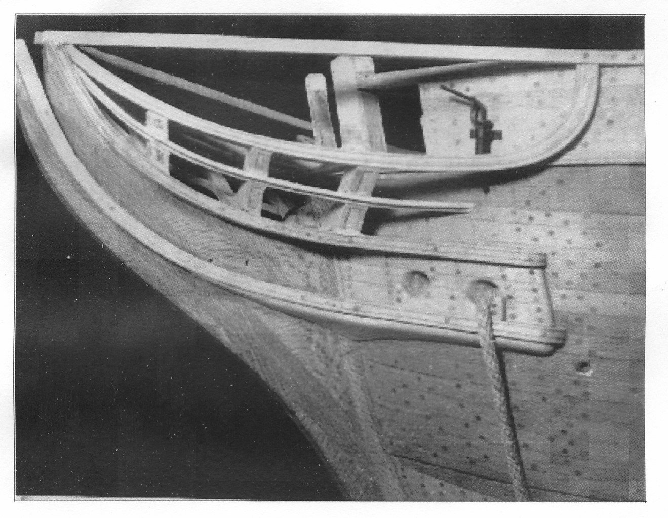
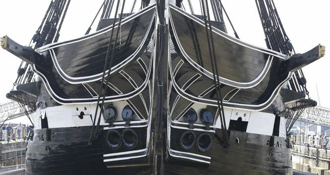
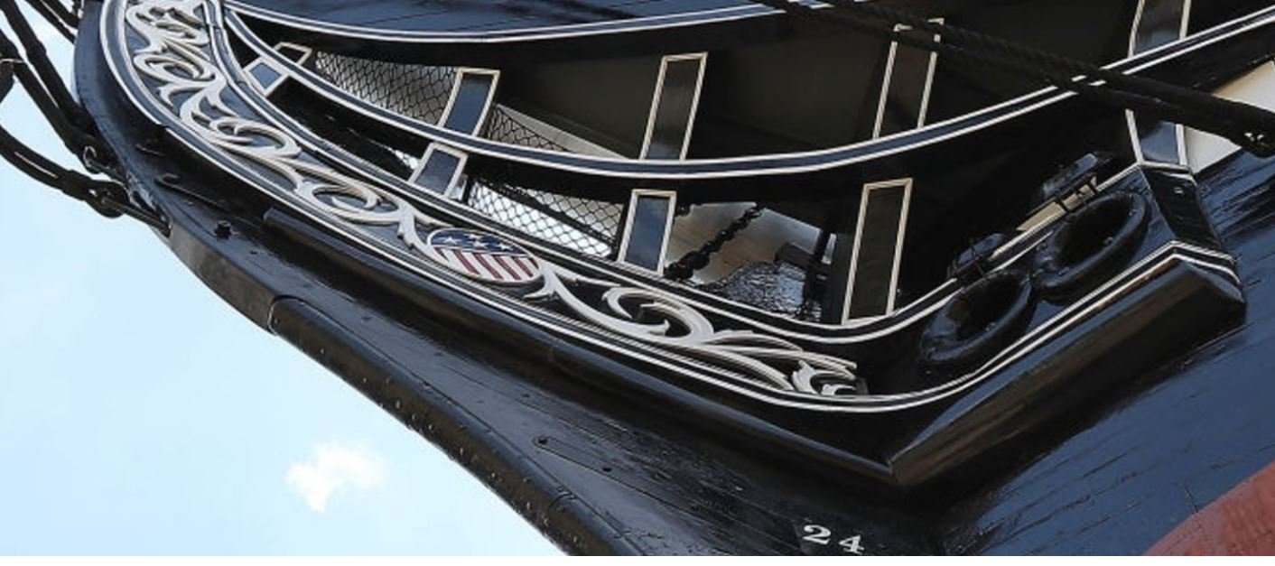
I thought it might be a good idea to give you a heads up concerning the pitfalls I encountered when doing the bowheads in case you are not aware of them already. The plans given on page 48 of the instruction book represent the restoration which was done in 1978 and is the current configuration. The scale is not given, but I was able to figure out that it is 1/96, and so can be used as is for the model. This configuration conflicts with the elevation plan in two ways: the cathead emerges from the hull at the forecastle deck level in the plan and in photo 24 on page 50, but does so just below the caprail on the real ship. Consequently the photo shows a "squashed" version of the bowhead structure compared to the real thing. The deck plan also shows the position of the catheads forward of their present position. I did not catch this until after I finished the build and saw that I had a foreshortened version of the structure. Here is a build photo of a superb model by Herb Ebson showing the simpler version of the bowheads shown in the Campbell plans: This is the configuration of the bows that the Revell model uses. The Model Shipways Constitution uses the current appearance. Perhaps one of the many builders of that kit might be willing to share the measurement from the stem to the cathead if you decide to use the plans given on page 48. By the way, the Ebson model uses real trennels, not simulated ones, and there are working brass sheaves in all the blocks. In case you do not already have them, here are some photos of the real ship you might find useful: Note the complex curves and variable beveling of the outboard edges of the bowhead timbers. Whenever I see a model of the Constitution, the first thing I look at is the bowhead. That is the most difficult part of the build in my opinion., and the Constitution bow is the most complex and challenging of any ship I have yet seen. The most successful rendering of this that I have seen is a build from the MS kit by Jerod Matwiy: One more thing. The cast metal trailboard provided in the kit is different from the current version, so some creative fettlin' will be needed to integrate it into the current configuration.
-
Amazing work! This kit demands great resourcefulness and creativity which you have shown. Congrats!
-
Thank you so much Ronald! I greatly appreciate your kind words.