


robert Lamba
-
Posts
93 -
Joined
-
Last visited
Content Type
Profiles
Forums
Gallery
Events
Posts posted by robert Lamba
-
-
14 minutes ago, piratepete007 said:
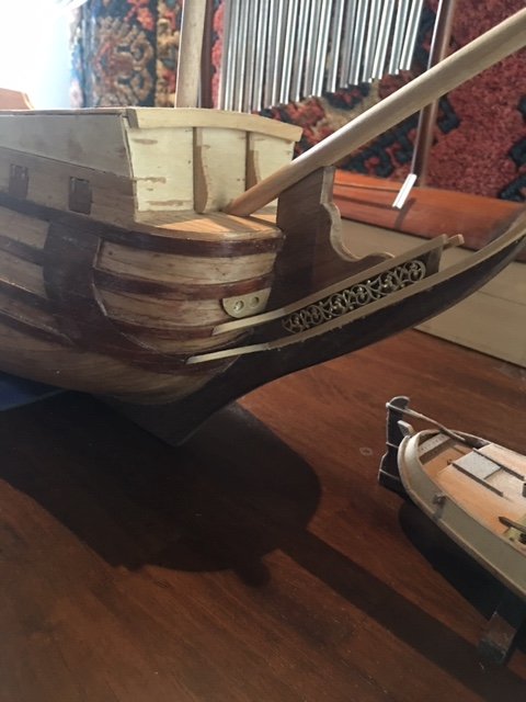
Robert, looking good and I must say that the wale positioning at the stern and the bow is very impressive. So often, this is a feature that can easily look clumsy on a build. Yours looks pristine.
Pete
In hindsight that bottom wale sould have curved down a couple mm's in the middle. It was better when I first laid it out before gluing, somehow I lost track of where it should've been.
-
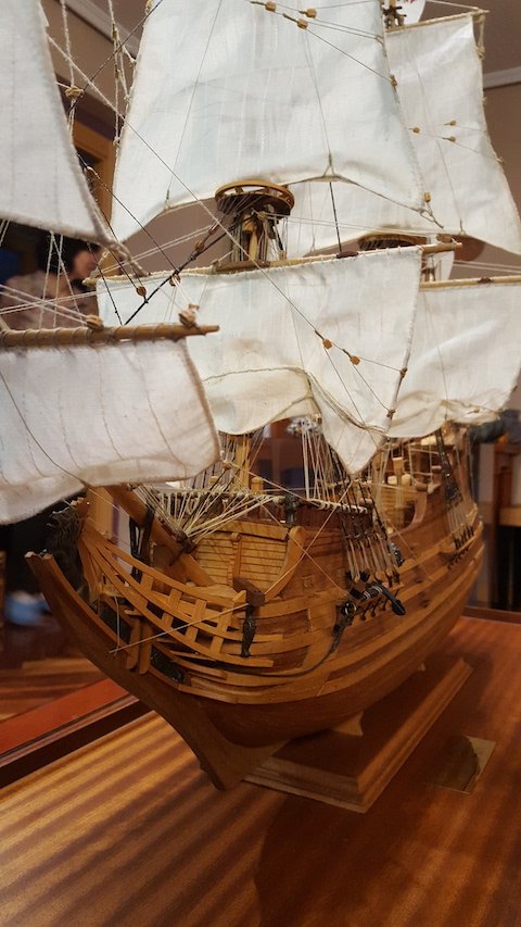
I've forgot to update my build progress! Most of my posts have been in 7 pages of conversation with PiratePete.
Here are some photos of progress to date.
-
On 8/19/2019 at 4:00 PM, greatgalleons said:
Hi there I'm watching your build with interest because I have this kit. It has four large sheets of plans and a small booklet with instructions and a separate parts list with wood size and lengths to use. It's still a bit confusing browsing through it all, very vague to tell the truth. The mast and spars wood are all pre cut to length in the kit but I do not see a detailed plans sheet for the mast dimensions and rigging in my kit. I don't know if I'm missing some more plans or if this is all that's provided. There is some material to use for making sails but no plans provided to plot out the shapes for the sails. I think this kit is terribly lacking in instructions to begin with. Hope to see your progress.
I'm being guided through the process by pirate pete I'm learning a lot. If you need advice I'm happy to pass on what I've learned and mistakes I've made. You probably have info that I'd find helpful as well, different minds come up with different approaches and solutions.
-
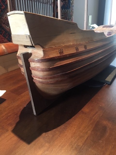
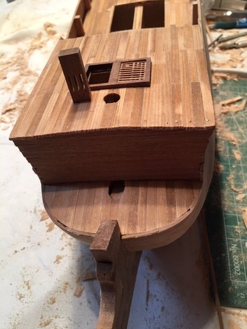
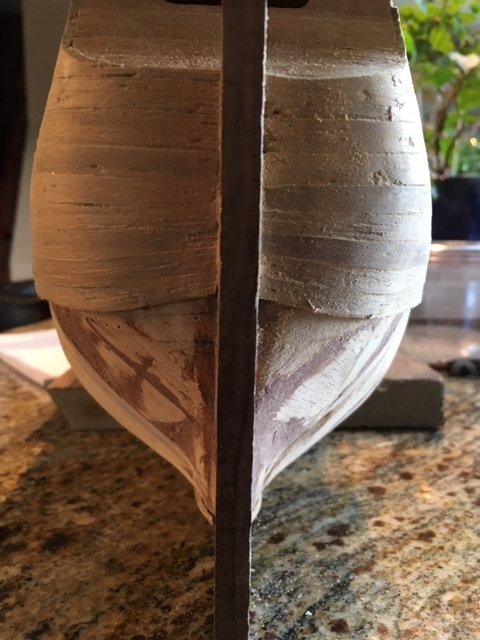
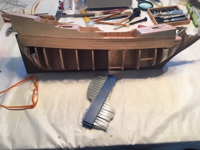
My first planked hull! Good learning experience for my next project, I made errors but nothing I can't hide.
I've applied two coats of satin varathane to highlight areas that may need more sanding and show the woods actual colour so I can custom match wood fillers to fill small blemishes. The hull below the wales will be painted, the bottom wale covers the seam where the lower planking met the descending planks in the middle
- piratepete007, marktiedens, mtaylor and 1 other
-
 4
4
-
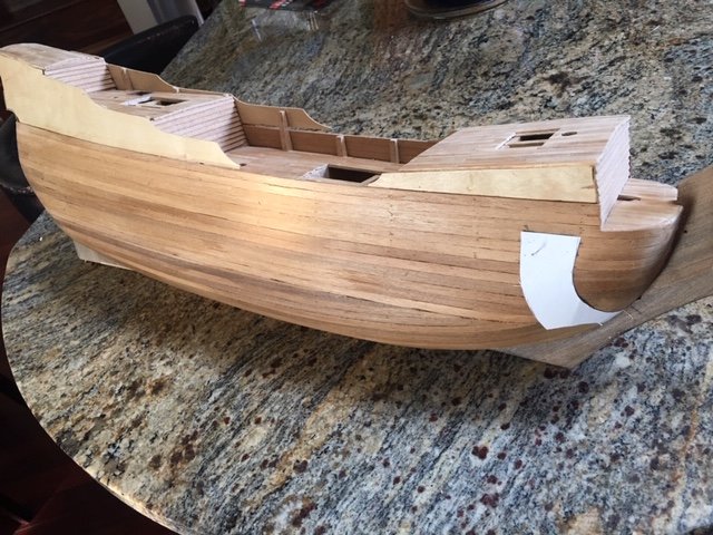
Slow progress, I think I spend ten times as much time looking and pondering my next move than I do working on the ship.
I've brought the upper planking down twelve rows and and the lower section up eleven, only 6 more required to close up the hull, but how to proceed with those last six🙄 ?
The plans I have show the lower planks curving up into I think what would be called wales at the stem, running beneath two wales running the length of the ship. At least that was my intention. I've been comparing what I've been doing to two other builds of Derfflinger whose builders chose a different approach, eliminating the upward curve of lower planks into the stem and instead ran them straight as possible. Both builders also left of the descending band of wales(?) on the bow, I have no idea why they're quite obvious on the plans.

-
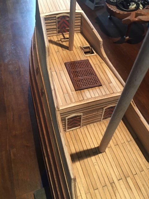
I've come across a number of knight-heads on other Derfflinger builds that offer different builders solutions for placement. One builder mounted his on the deck beside the hatch grates. Another mounted his on top of the grate, which looked alright but that doesn't seem a likely position as it wouldn't have any strength on an actual ship. The the third is below deck which presents problems for my experience level when it comes to the final rigging.
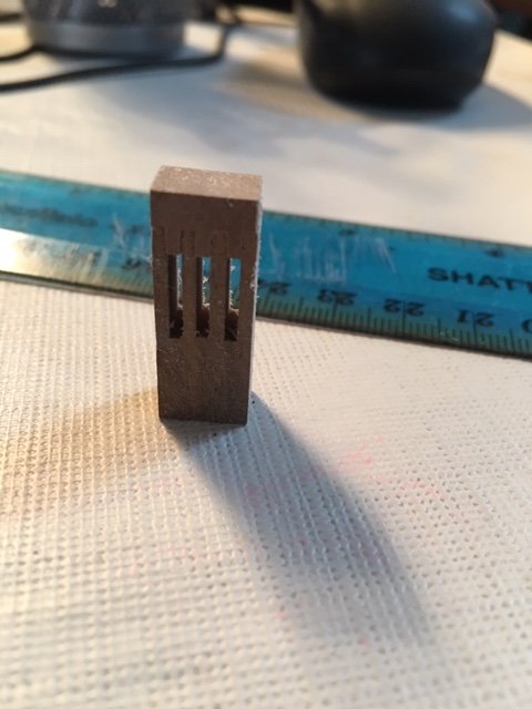
And then there is the issue of the knighthead itself, are there not actual pulleys inside the knightshead? there is no option for the that in my kit. Without pulleys how do keep the lines from pulling tight to the top of the knighthead, how do I simulate/build a pulley in such a tiny space?
-
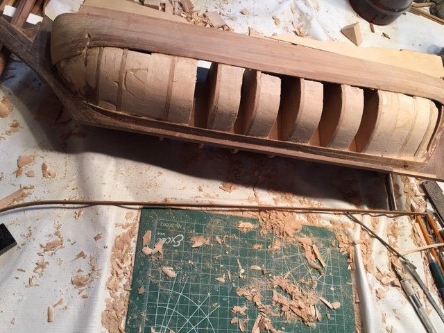
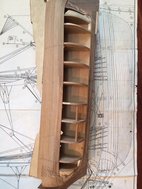
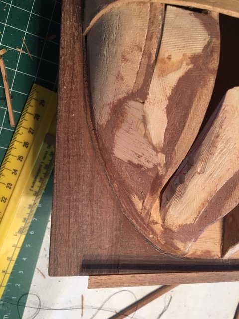
I made contact with pirate pete to gather some much needed advice. Put in additional filler blocks between bulkheads that should make the attaching of planks a bit easier in the stem and stern with their multiple compound curves. One side is filled and contoured which took about 6hrs, I made the switch to balsa from hemlock that I had used previously, hemlock is a pain to carve and shape. Not sure as yet if I'll do the center bulkhead on the other side those sections are quite straight and don't have the complex curves to the stem and stern.
-
how am I doing?
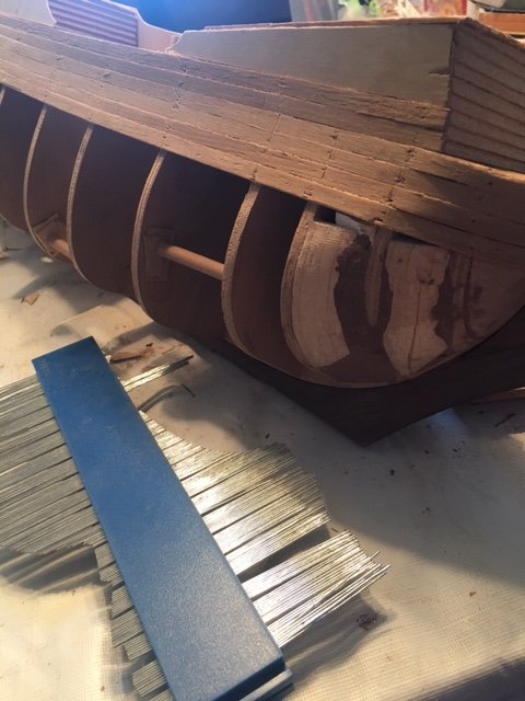
I've made some progress the bends at both stem and stern were a brittle planks kept breaking, splintering or splitting particularly at the stem. Finally solved that by soaking in ammonia and for the more difficult of the two ends, realized late 🙄where the bend begins I could use shorter pieces because they would be hidden.
Where I stopped now is approximately where the lowest wale runs, I didn't want to go lower until I got some feedback. I can see I'm going to run into crowding issues on the stem and the opposite with the stern.
-
I managed to shortened things up a bit on both ends, when compared to plans underneath it still seems a bit long. I'll experiment with some scrap pieces and see if I can get it shorter.
-
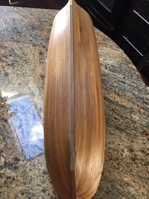
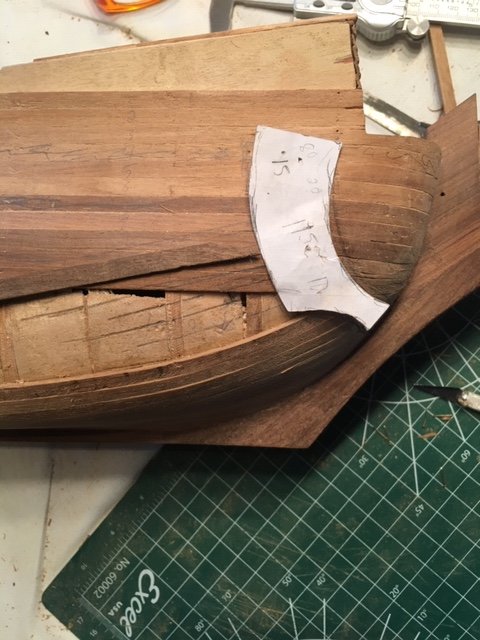
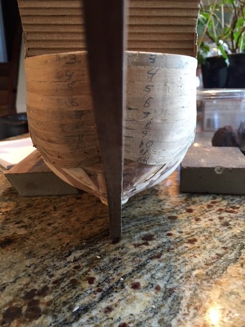
I tapered and beveled the garboard but haven't bent or glued it down. In the picture I have the garboard where it will end on the bow, is it to far up? I'm not sure how to bring it lower other than to reduce it in it's entire length. I
I read elsewhere not end with less than half a plank, does that apply in this situation as well?
-
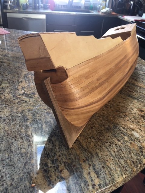
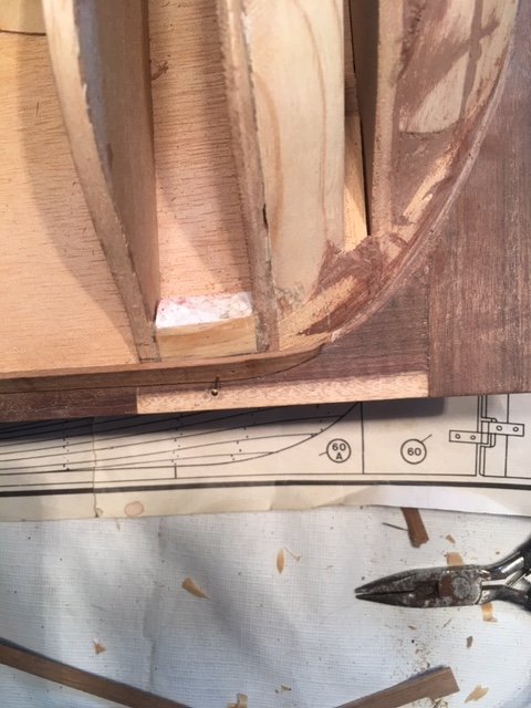
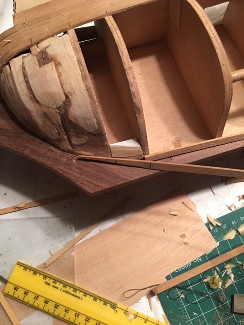
Studying at the hull wondering where to start planking I researched other postings and came across a couple that said I should rabbet the false keel for the planks to recess into and then be covered by the actual keel.
Well I don't have a false keel, the garboard for the most of it's length lies flat to the keel only at the bow and particularly the stern does it twist. How do I handle that?
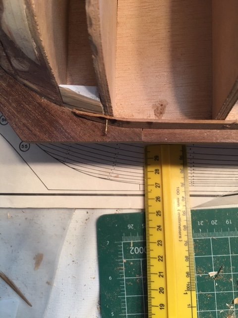
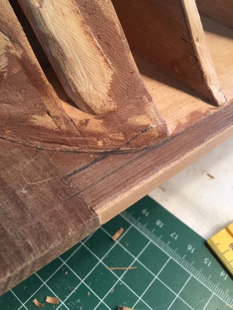
In one picture I've drawn a curved line the width of the planks where the keel meets the hull, on the upper stern it's 90 degrees so planks would butt nicely except for 41mm between that vertical and the bottom keel. What should I do for that 41mm? Do I need to carve out a channel in the keel or can I just taper the planking to fit?
The second picture I drew an extended line for the garboard at the stern where it begins it's upward, do I have placement correct?
-
I added four filler blocks to both the bow and stern, checked the curves with my contour gauge, shimmed any low spots with balsa, filed and sanded them till they blended in with curvatures. Skimmed both ends with wood filler and sanded smooth. Then I checked both sides of stern and bow with my contour gauge again removing any high spots with a file and sanding stick.
A few little details to attend to below deck and I think I'm ready to finish planking.
-
Excellent suggestion on the pin in the knighthead as there still access to the deck from underneath I may have look at seeing if I can drive a pin through from underneath. Or glue a block under the deck drill a hole in it to fit the pin from above more giving it more surface area to be glued.
Leaving the knighthead on the lower deck unglued until the rigging stage, I'd considered the same but wasn't sure it was a good idea but now that you confirm what I was considering I'll do that as well. I'll leave the grate unglued as well since the rigging needs to pass through it.
thanks
R
-
-
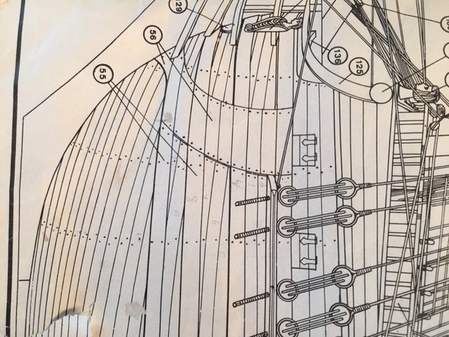
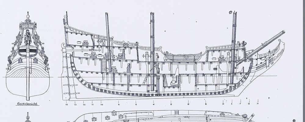
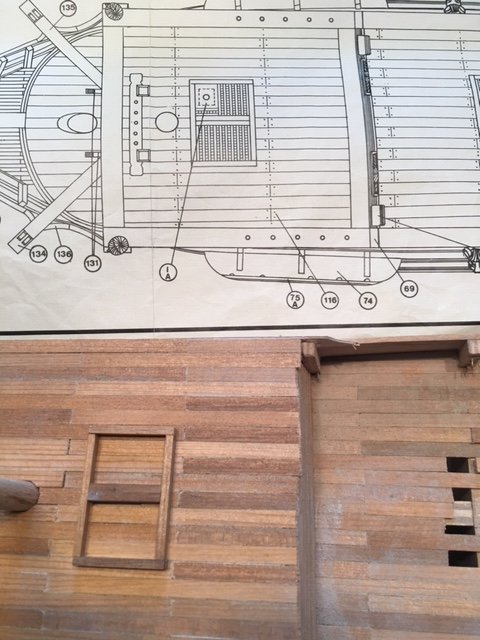
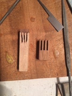
The knighthead is shown in this plan below the deck, reading some of piratepete's notes he extended them deep into the hull like the masts so as to be secure. Which is good plan but the two in my kit are deck mount, I could glue them to a longer shaft but that isn't going to any stronger than gluing directly to the deck.
Is there a super glue for wood? I could attempt two fabricate new longer knightheads, I'm not sure how that will go.
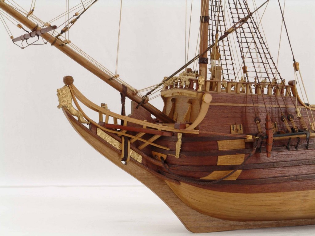
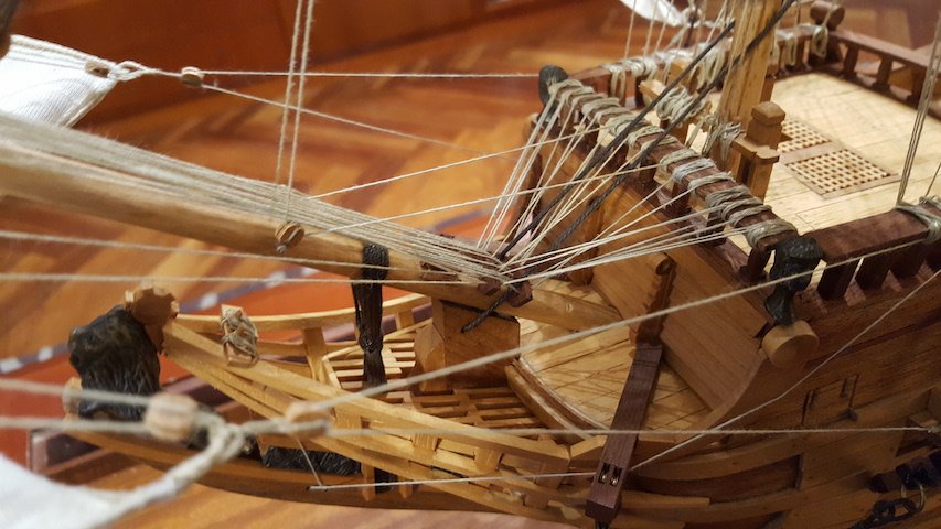
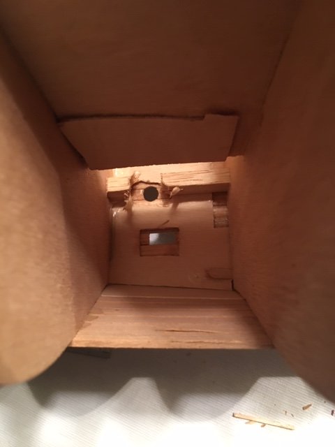
Accessing the knighthead below deck for rigging will be difficult to say the least, the hole to access it will only be 10x10mm. In the picture below just behind the mast is that a Knighthead, if it is then the builder either made an extended knighthead to bring up from the lower deck or he mounted the shorter knighthead that came with the kit onto the deck.
-
Thanks Mark I'll get in contact with pirate pete and see what he can tell me.
- mtaylor and marktiedens
-
2
-
4 hours ago, amateur said:
All derflingers are build according to the same plan: a plan drawn by RolfHoeckel , a German wirter on historic ships. The plan is drawn somewhere around the forties, and is notquite historically accurate.
the internet is full of it (eg here https://www.westfriesmuseum.info/critical-look/ )
there is definitely a knighthead in that position,, just as Mark shows. Whatever Dikarmade f it,it is not a galley for sure: ships in that period had there galley amidships, and is was just a brick box, nothing fancy.
Jan
thanks that leaves no doubt I'll have to bookmark that page for future reference
- mtaylor and marktiedens
-
2
-
Dikar has been gone for a long time so there's no one to contact.
There is no side view plan of ship interior and I as yet haven't found an unidentified part that resembles a knighthead. There a single knighthead for the rear mast.
I did finally did find a clear view of the opening, on the side of the Dikar box🙄, it's very small picture I needed a magnifying glass, but sufficient enough to see there was no knighthead protruding. Whatever was used is invisible below the deck.
I'll need to fabricate a part, placing it securely below deck will not be easy nor will be attaching the rigging. An eye head screw would be simple and secure but not an aesthetically ideal solution.
- mtaylor and marktiedens
-
2
-
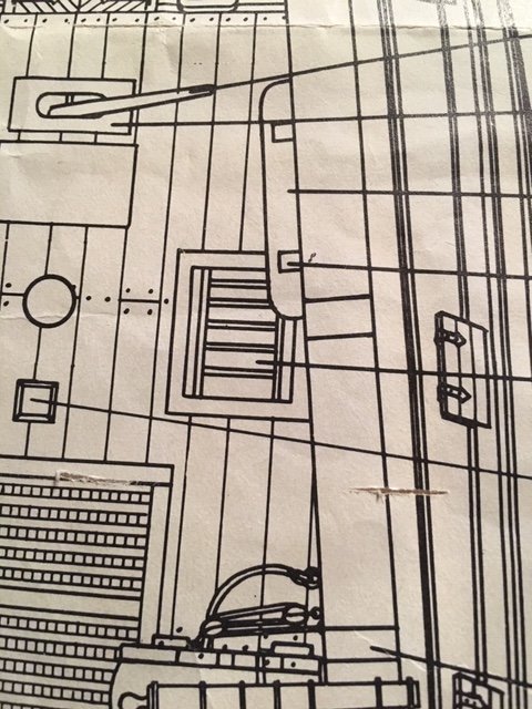
I think you may right. I laid the rigging plans next to the deck plan and there is a large block pointing in the correct direction and the only thing there on the deck plan is the mystery circle and square.
I looked at other photos of Derfflinger by the other builder but has nothing there, it's possible he didn't know either as it's not on the plans.
So what do you make of the plans, how should I interpret that circle and dotted line square, what do they represent?
- marktiedens and mtaylor
-
2
-
-
On 2/14/2019 at 10:11 PM, marktiedens said:
Is it possible that it`s a knighthead for the lower yard halliard? Some of the ships of this era had a knighthead fastened to the lower deck & passed through a hole in the upper deck - Vasa for example. Those set-ups were usually offset to one side so as not to foul the stays.
Mark
Thanks for the suggestion, I had to look up what a knighthead was. If you look at the plan I posted aren't there two just forward and offset either side of the area in question? Do you think there would be another on the lower deck?
-
11 minutes ago, mtaylor said:
I don't think they "galvanized" steel back then. Stoves were either on a slab of iron or a layer of firebrick. The chimneys were iron and black.
I only mentioned galvanized because that's what I'm familiar with. I have been looking for other examples from what was used in 1683 but no luck so far.
Iron is possible but that seems heavy for that application, tin, copper, brass or bronze are all options.
-
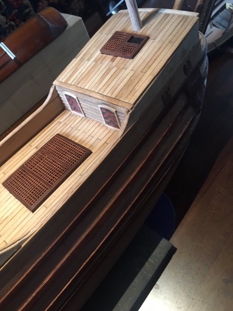
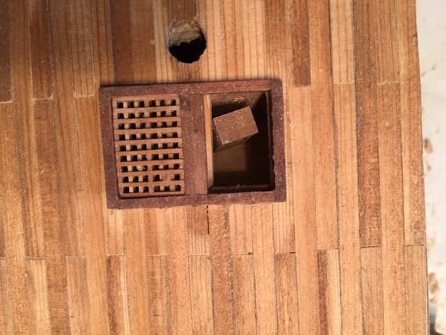
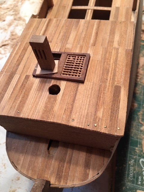
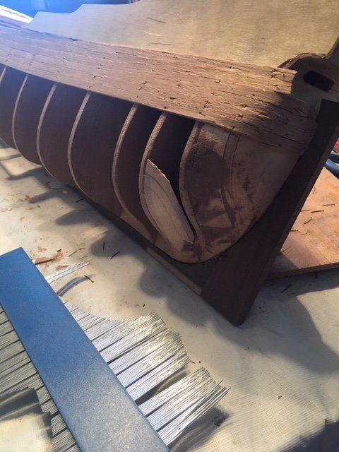
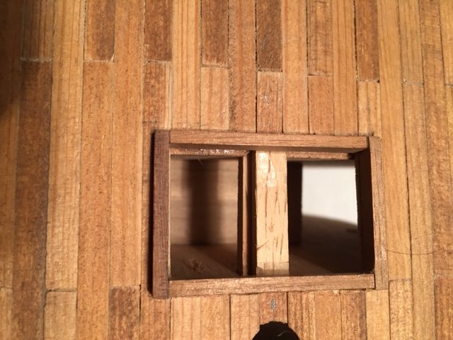
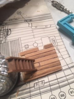
Well the mystery of where part 1A went is solved I cut of the grate opening and 1A can be clearly seen below. A bit pointless having it there if a grate is cover is fully obscuring the opening below. I'll just paint it a flat black. Unless I can find a very small thin piece of copper for the the Flue collar I may use the soft metal from a wine bottle seal they're normally a steel grey, not sure what I'll use for a flue.
So Dikar has a lower deck for a place where I really didn't need one and then where there should be one at the bottom of a staircase to a lower deck there is none. Being very inexperienced 40 years ago that never occurred to me so now I have the pleasure of maneuvering/fitting a lower deck up inside a partially planked hull.
-
If you click on the image above it should enlarge. There are two halves to the grate opening with a supporting framework, so typically a full grate on each side. In the image it appears the grate on top is divided as well, the piece on the right still in it's frame and the left side below the grate frame. I don't know what to make of that.
You mention a steel plate, that would resemble the flue system we still use today. A collar of galvanized metal with the flue in the center, the collar isolating the flue from combustible material.
I'm going to open up the deck under the grate next and maybe get a better idea of how to proceed.
- GrandpaPhil and mtaylor
-
2

1683 Urca Derfflinger by Robert Lamba - Dikar - Scale 1:62 -
in - Kit build logs for subjects built from 1501 - 1750
Posted
You can use the plans themselves for a template of the sails and mast dimensions, it only took me 40 yrs to realize that the plans are actual size of the finished model, lol.
Four sheets of plans is all that came with the kit, plus the materials list and instruction booklet. I lost my instruction booklet a couple decades back along with the parts list, I'm guessing as to what goes where and the construction procedure. I've had to backtrack and guess at a lot of what I've done. Pirate Pete has helped enormously. If you want to share photos of your parts list and instruction booklet it would be a great help to other Derflinger builders.