Martes
-
Posts
984 -
Joined
Content Type
Profiles
Forums
Gallery
Events
Everything posted by Martes
-
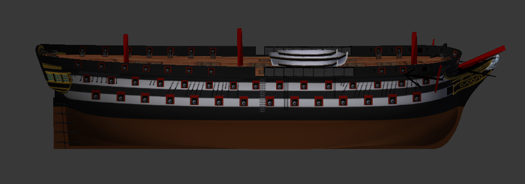
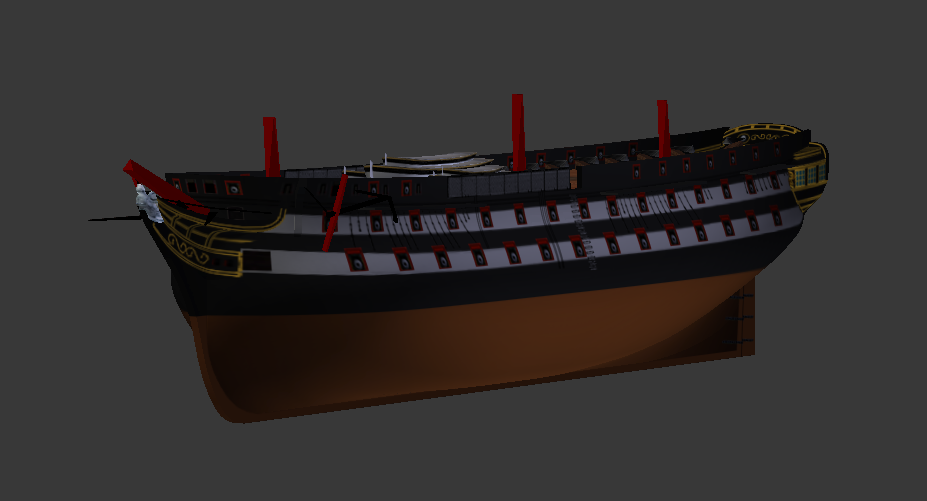
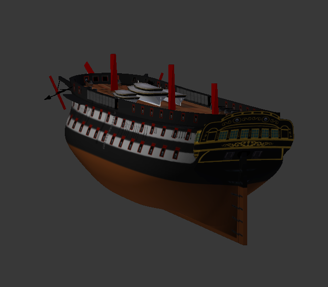
Thanks, @Kestros1 Indeed it is much better, but it still ignores the planking, that that should look something like this (this plan is for a different ship, of course): The lines on the original plan are dashed, the planking thickness for each frame is in solid lines. Note, though, that especially on the rounding of the bow, the plank thickness is perpendicular to the surface, and thus in the transverse cut will appear significantly thicker (see this post where I explained it, for example). So your real outline, accounting for the thicker keel, should look something like this (note the waterline marks, the give a rough idea of the planking thickness in corresponding places, as well as the steps at the intersection of the frames and the keel): It is possible, Fusion 360 has some feature to automatically make an envelope of at least fixed thickness around a complex mesh that follows the frames (like Solidify operator in Blender) that make this process somewhat easier, but I haven't found any reliable way to do it except manually.
-
I am very much afraid it is little late, but hawseholes really ought to be closer to the centerline, and their cuts are parallel to the centerline, not perpendicular to the surface of the hull in the place of the cut. And by the way, why the sudden rectangular cut of the bow? It was round on those ships.
-
It's a very common error, everybody falls for it at some point. Planking may appear something thin and negligible, but in fact it adds a very substantial volume to the outside form of the ship. Also note that it's the thickness is not uniform, and the planking is thicker towards the wales. Figures in the great cabin is a very nice touch. Will the top cabin be removable to manipulate them?
-
Does the model include the planking or not? The front view makes the hull appear as if it includes the planking. The stern view shows the hull as if it follows the frame lines. By the way, there is a good quality set of plans of her sistership Tourterelle on wikipedia: https://commons.wikimedia.org/w/index.php?title=Special:MediaSearch&fulltext=Search&search=tourterelle+rmg It shows the French configuration, but it may be of assistance. I suppose the extremely wide keel is for the plastic endurance, but those small frigates never had the poop cabin aft even in French configuration, and the deck should not be flat, but slightly curved towards the centerline.
-
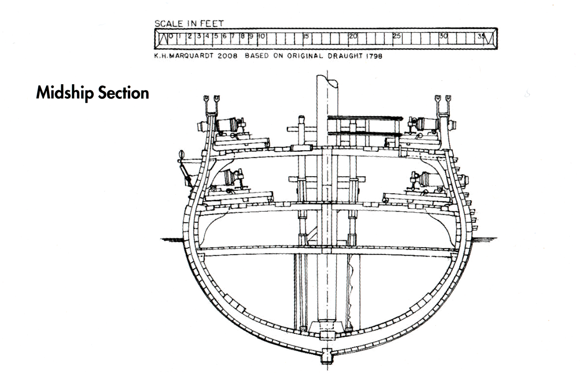
The AOTS book contains the frame thickness in cross-section views (p. 62 and forward)
-
Also, boolean can come in conflict with mirror, especially if both objects have mirror before boolean is applied, and generate mirrored geometry inside the mesh.
-
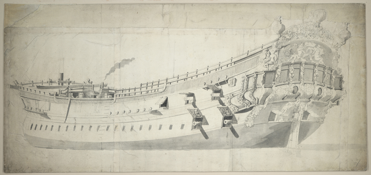
https://commons.wikimedia.org/wiki/File:'Pelican'_(1777)_RMG_J7944.png
-
3D Brig 'Rose' in Blender 3.3x
Martes replied to 3DShipWright's topic in CAD and 3D Modelling/Drafting Plans with Software
Yes, just submerge her to X or XI, and it will look all right. By the way, get rid of those marks as well, they were invented late 19-th century and weren't nearly present in the age of sail. -
3D Brig 'Rose' in Blender 3.3x
Martes replied to 3DShipWright's topic in CAD and 3D Modelling/Drafting Plans with Software
It is indeed a nice touch It does, however, add to the list of anachronistic features that could not have been present at the end of 18th century, like the netting around the guns and the dockyard support rings. As I wrote sometimes ago, the waterline should be higher. It does depend on the stage of the cruise, of course, but the ship does ride too high both to be stable and to have sufficient weapons and supplies on board in your representation. It is not unknown that empty water casks would be filled with seawater to preserve the trim of the ship in some cases. It should be somewhere around XI mark forward. The coppering may reach the waterline, or be a little bit lower. And the gunports and oar ports. While they are usually left open, it should technically be possible to safely shut them with board lids, and for that they need to have sills, like a door: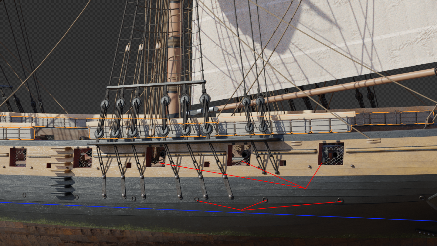
-
That's absolutely pixel-induced illusion. And I am quite proud it's so convincing
-
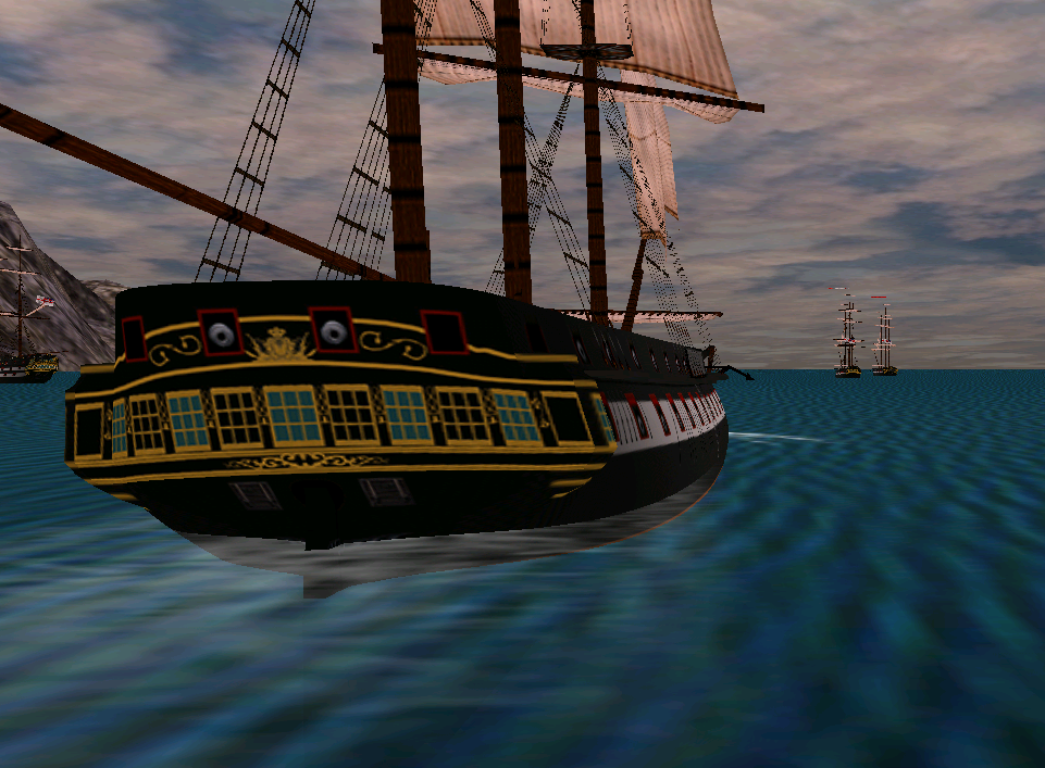
Nate, First of all, thanks, I am very glad you like them Remember, I deal with a very specific game, which is extremely old and imposing a number of not very obvious restrictions, so everything I do is somehow directed to circumvent those restrictions and still get aesthetically pleasing result. The rule is 1 object -> 1 material -> 1 texture. Multiple objects can share a material (and the texture), but an object cannot contain more than one and a material cannot reference more than one texture. The game can substitute the textures under certain conditions at runtime (config file sets the paint schemes for different navies and damage textures). Also, I have to be very careful with order in which the objects are processed during export. This order is used by the game engine (which is OLD and based on DirectDraw, not even Direct3D) to determine which object will obscure all the others if it is visible. If I place the deck after the hull, for example, it will poke through when rendered. This imposes a limit on the number of objects, their placement and the number and structure of the textures. Obviously, there are no normal maps or anything like it. Everything is just drawn as is, including shadow to give the hull a bit of volume. But then, when you look at a ship from any distance, you won't see any planking details or anything like that under the thick layers of paint that usually covers the hull. I more or less used the Unicorn for the paint basic scheme And to make any modification relatively easy, the I mostly use "project from view (bounds)" on the hull and the stern, since that allows to move the vertices around as much as I want and quickly reapply the texture (which is, essentially, a painted side or stern view of the ship) afterwards - as long as the limits of the bounding rectangle remain the same. What I am not sure is if any of those tricks can be useful for more modern environment, but they definitely work for me.
-
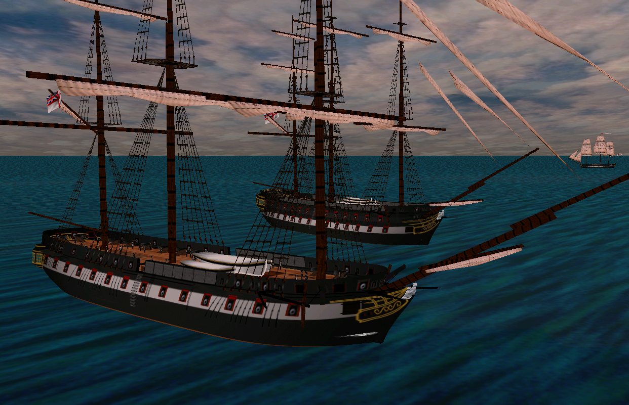
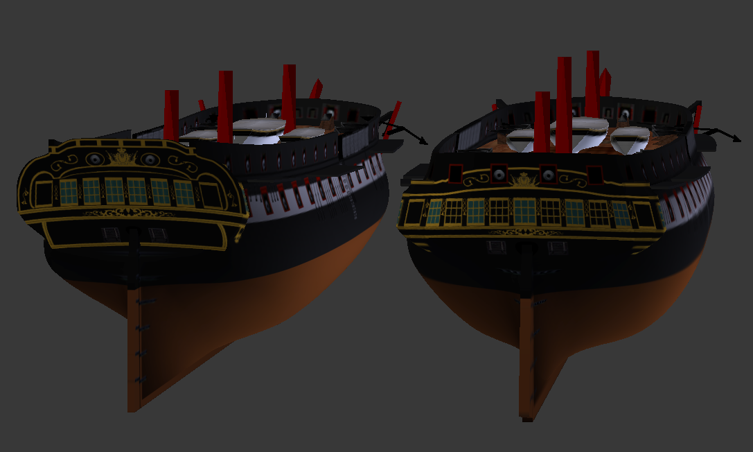
I found that while I really like the black paint for the flush-decked long 74, an absence of a regular, two-striped variant greatly disturbs my sense of order. So I made an appropriate skin to mend this:
-
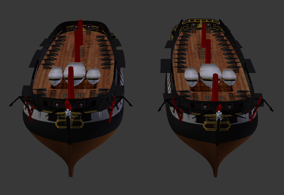
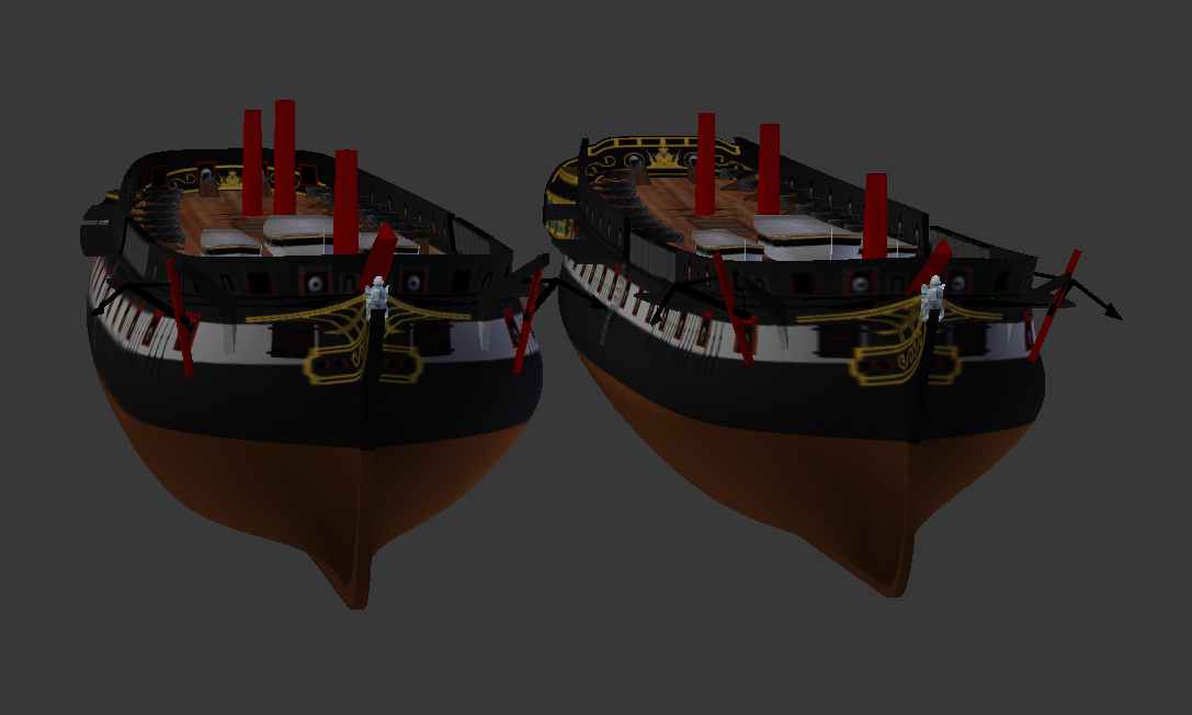
A close-up on both variants of cut-down 74.
-
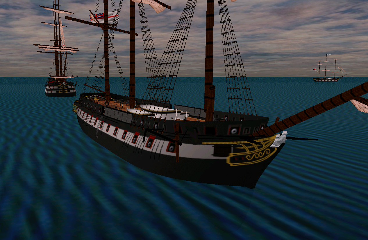
Fixed the mast placement in config file:
-
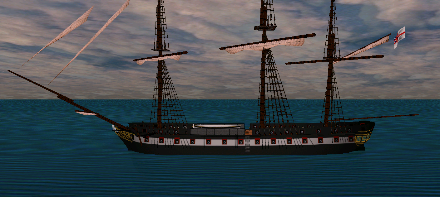
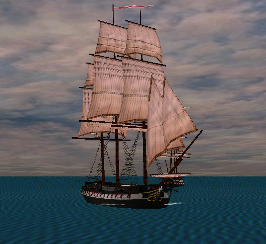
Traditional post-launch sailing test:
-
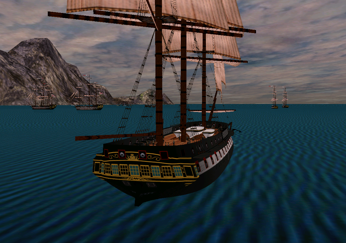
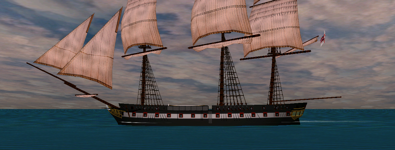
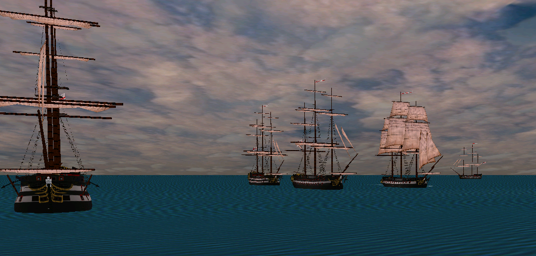
To emphasize the sense of scale: 74-razee, Egyptienne, Liffey, Belle Poule. Keep in mind that Liffey was considered large for a frigate, and was already carrying 24pdr battery. Belle Poule is admittedly small (although, again, for her time she was also relatively large and several similar ships were rearmed with 18pdr guns against original 12pdrs in British service), and what I miss here is the "standard" 38 (18pdr) - that would be the Virginie when I finally get around to rebuild her. And don't let the decorations and raised heads fool you - all of them are still French hull forms.
-
Colossus, being built to the lines of the Courageux of 1753, is also sufficiently French in that regard. They are both relatively sharp at the entry (quite unlike the absolutely French ships by Forfait, but we'll leave that at the moment), but the difference is in absolute values, of course. She's simply narrower at 43' 8" against 48" breadth of the 74 (and the razee), with only 2.5 feet difference in length and that shows. After all, she was built for 24-pounders and speed, not 32/36 pounders and standing in the line of battle.
-
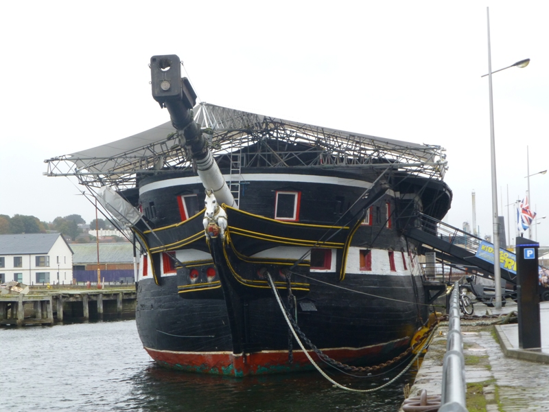
HMS Victory Renovation - Outer Planking Removed
Martes replied to Steve20's topic in Nautical/Naval History
Curiously, Lambert (Last Sailing Battlefleet) mentions that certain group from Rochefort seems to have succeeded to assemble necessary funds to keep her, but then the Admiralty got cold feet about returning her to France and said she won't survive being towed cross-channel. Well, she didn't, explosive charges made sure of it. -
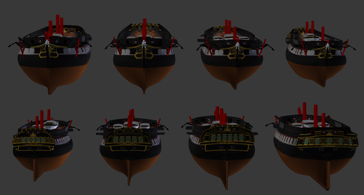
One of the things that constantly amuse me is when somebody compares L'Egyptienne to a 74-razee. Yes, they are (more or less) of the same length. But you can't mistake one for another (and not because of the stern): L'Egyptienne (top right, bottom left) is much slimmer, her hull long and narrow, compared to the round bulk of the cut down 74-gun ship.
-
The next logical step in exploiting the hull of the Colossus is to razee it completely, creating a regular - if very, very heavy - frigate. As those conversions took place after 1815, almost all the ships were fitted with this or that variant of round stern, and they all were different, so I had to choose one of them, which certainly wasn't easy. You may note that some of the stern lights are actually shut and fitted with faux-windows, and the glassed ones could have served as additional gunports, except the central one, where the rudder head is located. But it was very, very difficult to choose between this variant, with smaller, 2-window quarter galleries and the more traditional with 3 windows, but in the end I went for this one as slightly more exotic, but still pleasing the eye, as far as this arrangement can. For stern reference, I used the the plan for the Vindictive. Anyway, the closest ship to my interpretation was the Grampus (ex-Tremendous), which was originally almost completely similar to the Colossus. And I am not nearly done with this hull.
-
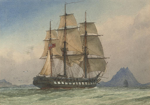
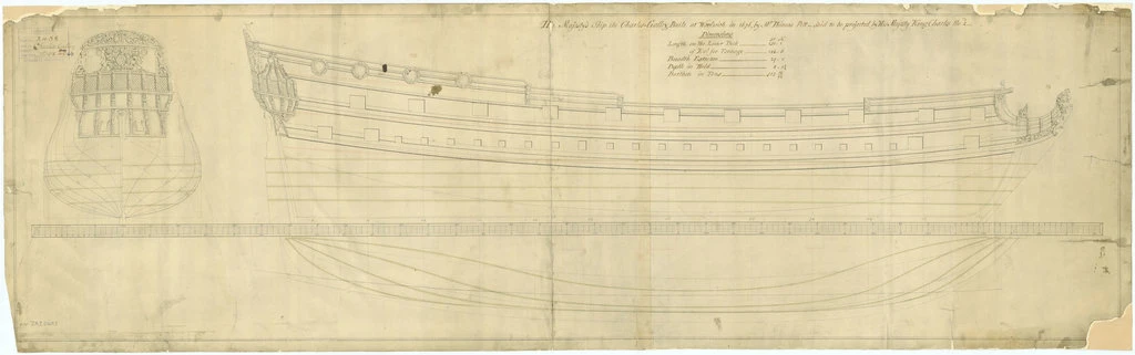
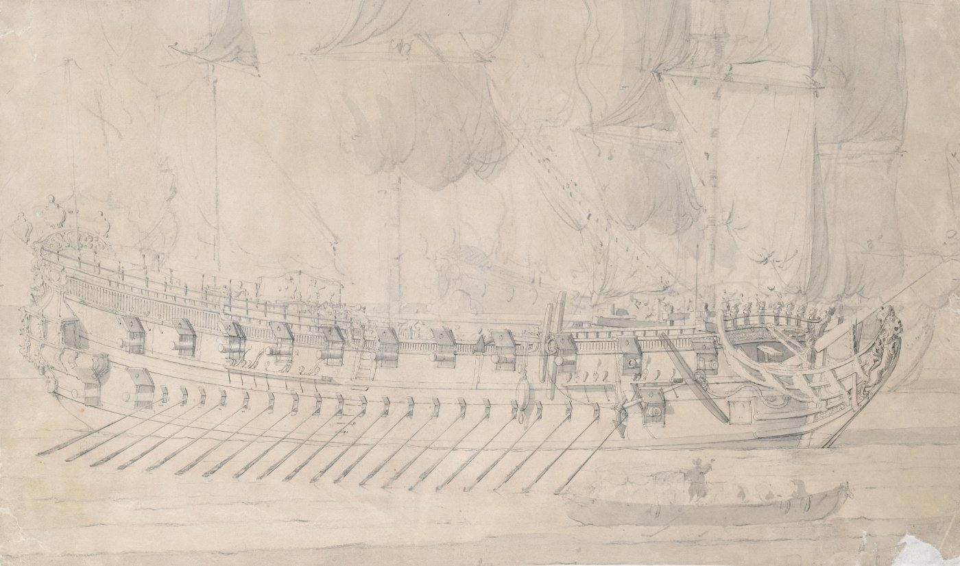
There is a plan in RMG collection (it is probably a later, 18th century copy or a reconstruction, but that's the closest you can get): https://prints.rmg.co.uk/products/lines-plan-for-vessel-charles-galley-1676-j6899 And a couple of portraits by Van de Velde:
-
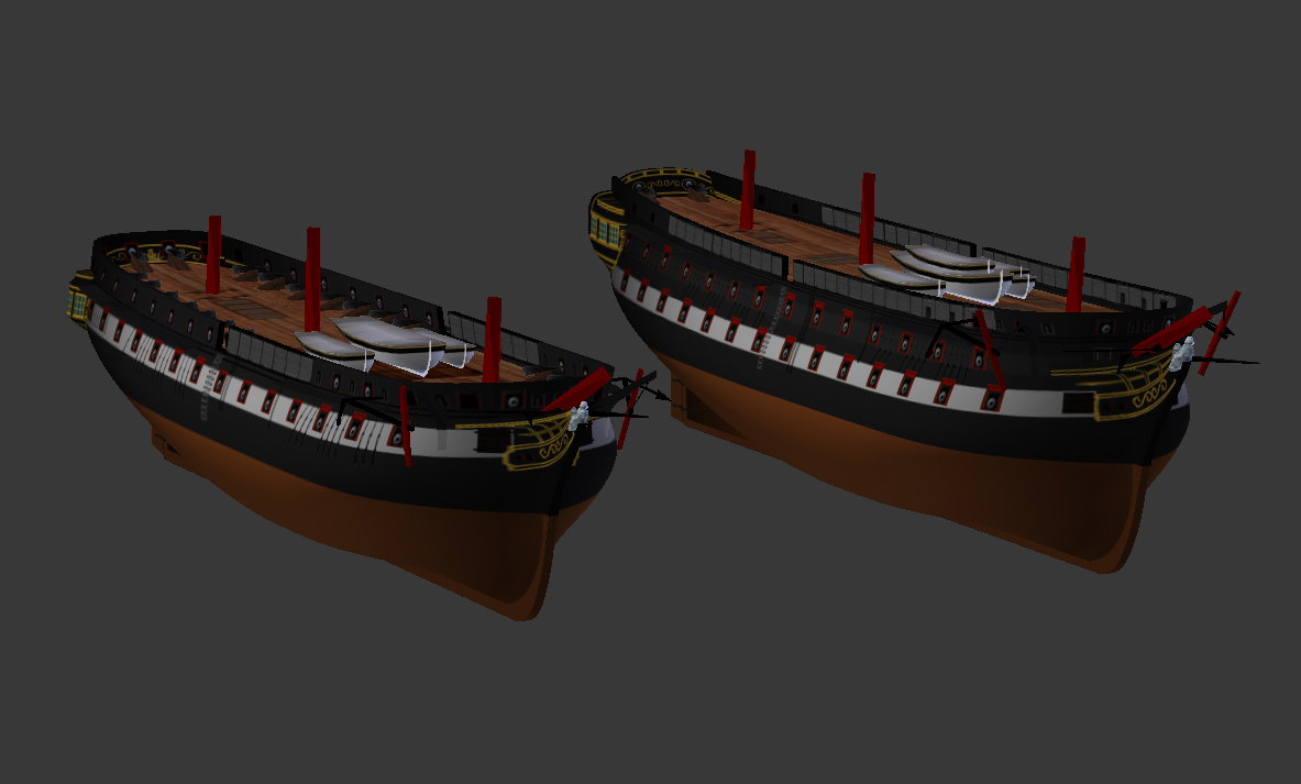
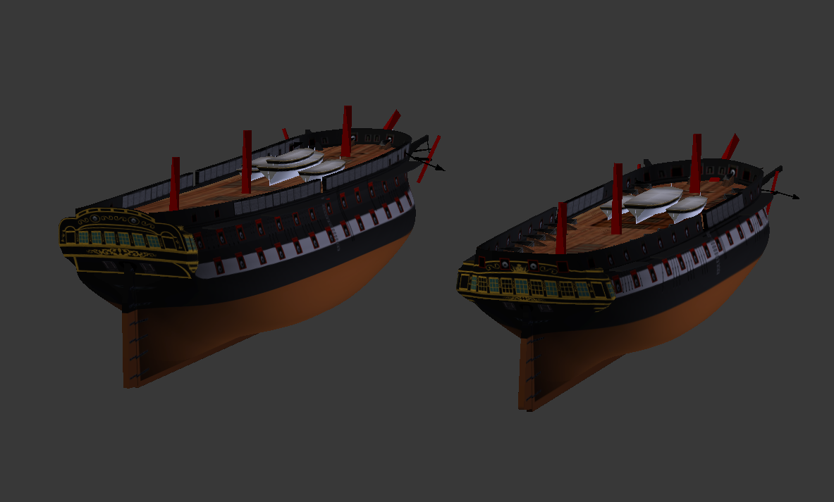
USF Confederacy in 3D | Blender
Martes replied to 3DShipWright's topic in CAD and 3D Modelling/Drafting Plans with Software
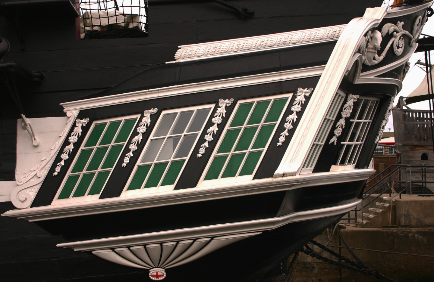
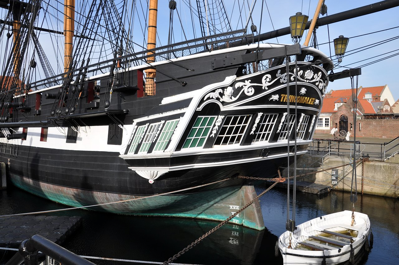
It is also probable, that parts of the side windows would be shut as on Trincomalee above, to provide some privacy to the galleries And the same with the stern windows, as maybe they would have moved the usual settee from the stern to enjoy the view, but there is still the box of the rudderhead to fit in the center. On a side note, what is quite peculiar, that the her hull lines look neither British, nor French. They appear to be strongly influenced by F. H. af Chapman's "Architectura Navalis Mercatoria" and his "Treatise on shipbuilding". Technically this is entirely possible (the books were published in 1768 and 1775), but very interesting nevertheless as to the why and how was this style chosen, being quite the cutting edge of ship design at the time.- 107 replies
-
- 1
-

-
- Frigate
- Confederacy
- (and 1 more)
-
USF Confederacy in 3D | Blender
Martes replied to 3DShipWright's topic in CAD and 3D Modelling/Drafting Plans with Software
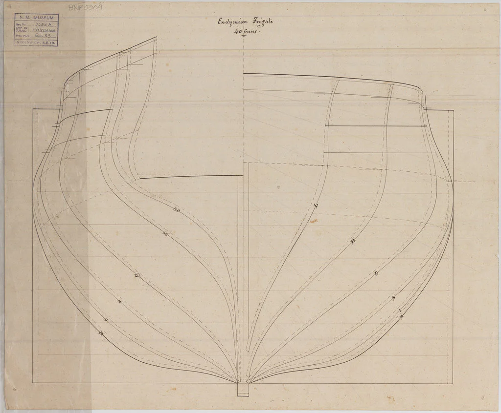
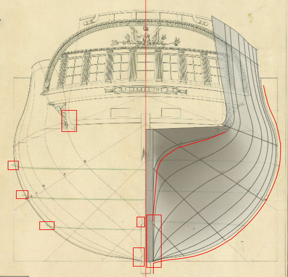
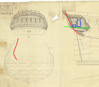
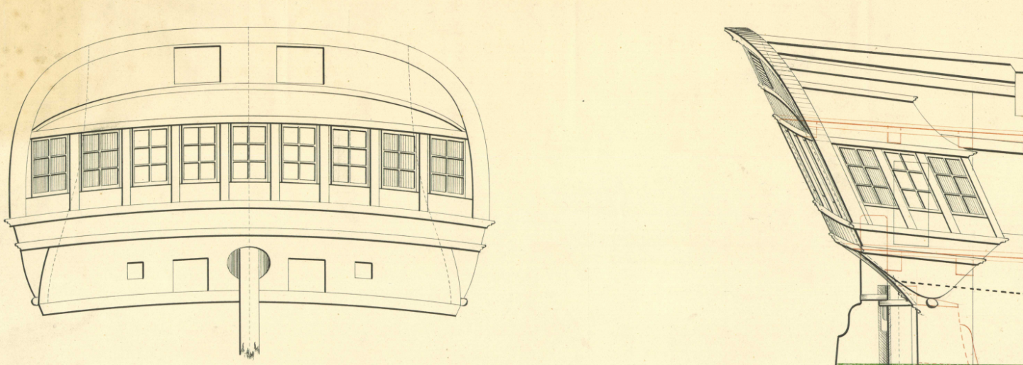
Fitting the lines and the stern on the original plan (low-res as it is): you can see that the last line replicates the frame of the transom and all the way up to the taffrail. This line is not vertical if viewed from the side, but represents the aftermost edge of the hull framing. I marked the tentative positions of the door and the seat of ease in blue, with green marking the level of the deck. The window, as you can see, is clearly crossed by the hull and thus is definitely dummy, French style.
- 107 replies
-
- 2
-
-
- Frigate
- Confederacy
- (and 1 more)
-
USF Confederacy in 3D | Blender
Martes replied to 3DShipWright's topic in CAD and 3D Modelling/Drafting Plans with Software
It is very, very unlikely. I am not aware any ship at that time would be built like that - this renders the gallery unusable, after all.- 107 replies
-
- 1
-
-
- Frigate
- Confederacy
- (and 1 more)
-
USF Confederacy in 3D | Blender
Martes replied to 3DShipWright's topic in CAD and 3D Modelling/Drafting Plans with Software
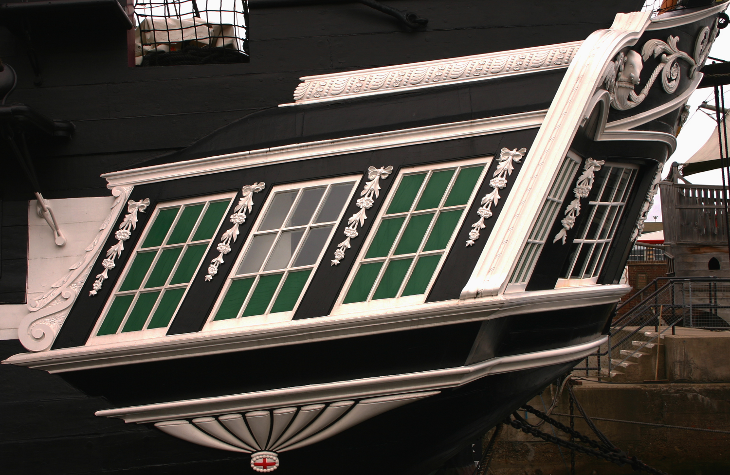
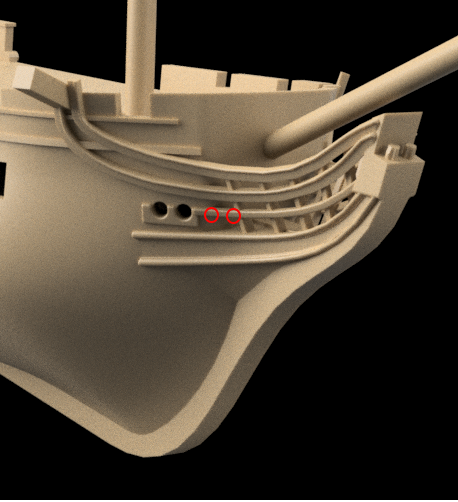
that is. I am not sure if those windows overlap with the ship framing (on some French ships they do), but quarter galleries usually did not have open windows to the stern. Diana Trincomalee L'Africaine - note how the dotted contour of the frame crosses the second window and the position of the door inside. There were different manners of decorating the places where those windows would be, from putting dummy window frames or wooden blinds to various decorations there, but since the plan shows framed window, so it should be.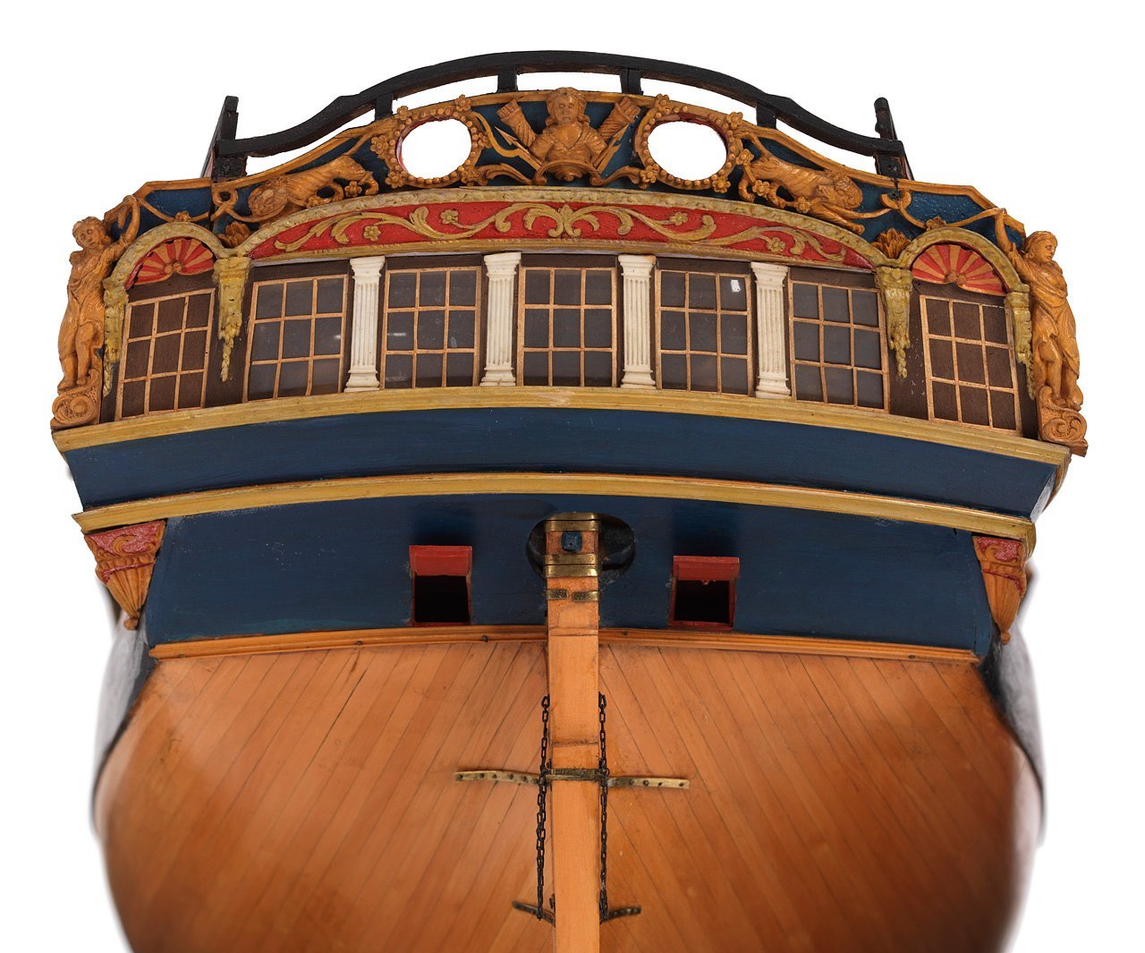
- 107 replies
-
- 2
-
-
- Frigate
- Confederacy
- (and 1 more)