Martes
-
Posts
981 -
Joined
Content Type
Profiles
Forums
Gallery
Events
Everything posted by Martes
-
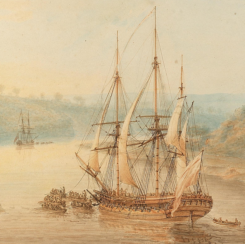
The original file was at Bonhams, I think, under the title "A frigate under tow down the Avon Gorge". But I can't find it now, not on the fly at least. A very similar image, though, is on ArtUK site: https://artuk.org/discover/artworks/the-avon-gorge-at-sunset-188005 And is attributed to Nicholas Pocock. However, when I look closely, it may be possible that the sail is not like a jib, but has a vertical cut forward and is additionally fixed to the foremast somewhere under the top. So it begs the question - whether this was a standard sail supplied to ships for such situations, to emulate fore-and-aft rig (and how effective it could have been?) or this is a local captain's initiative and improvisation?
-
Does anybody have any idea what the sail on the mainmast is? It looks like an oversized jib.
-
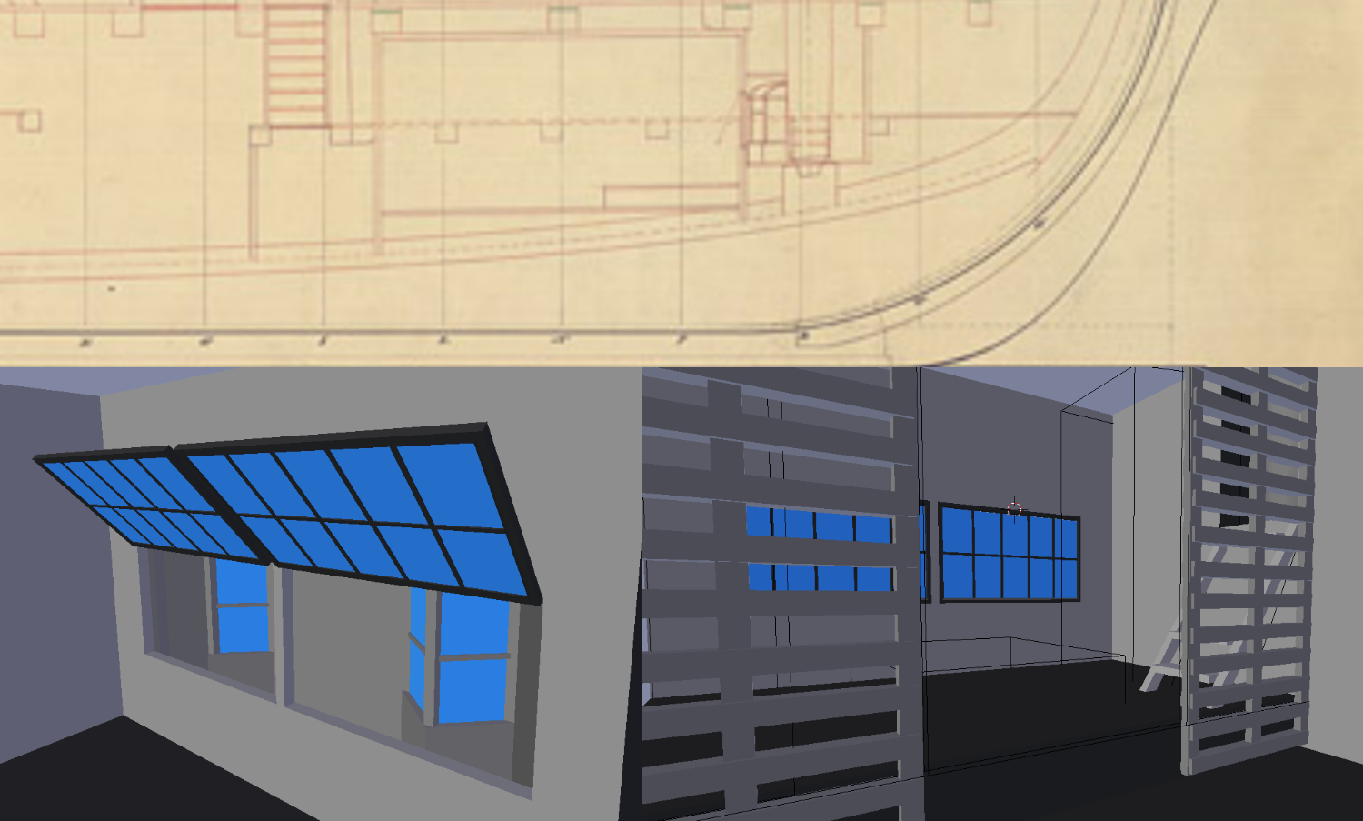
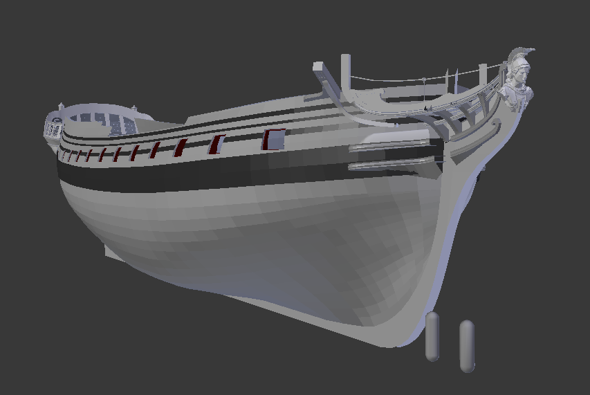
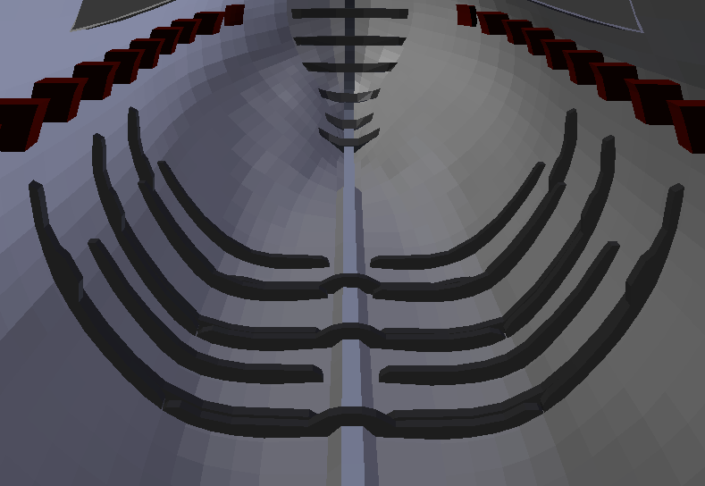
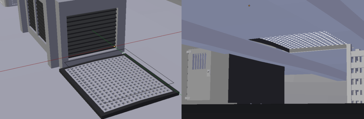
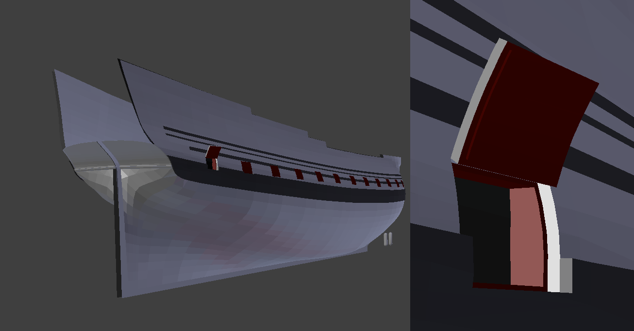
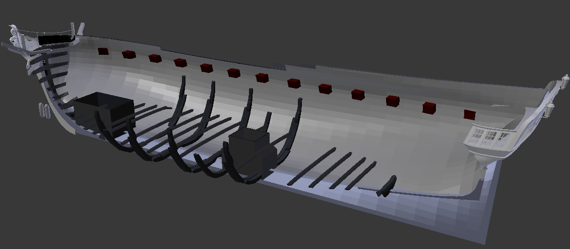
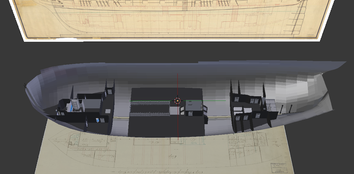
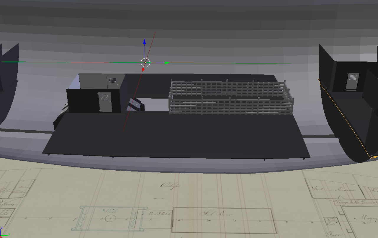
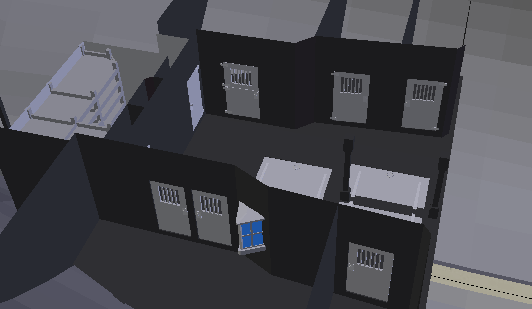
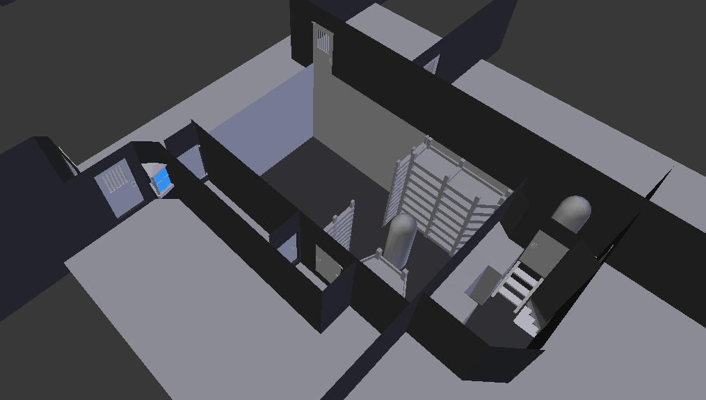
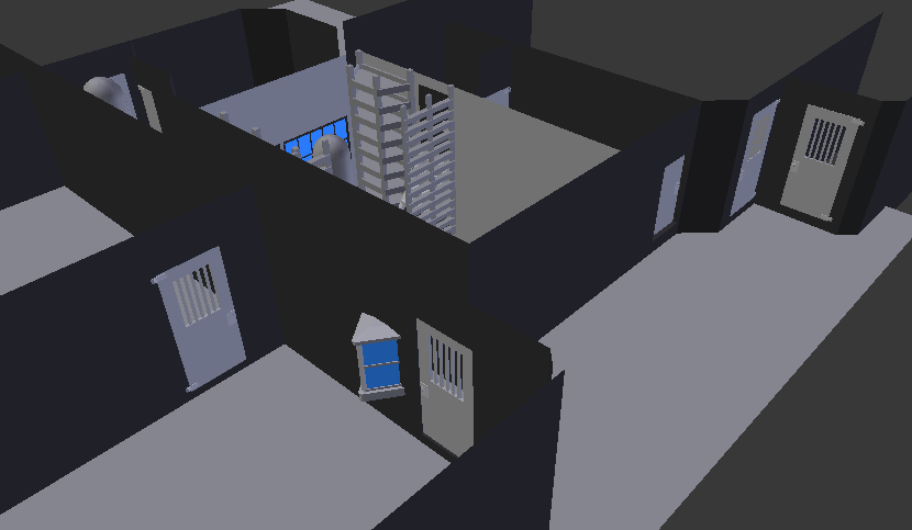
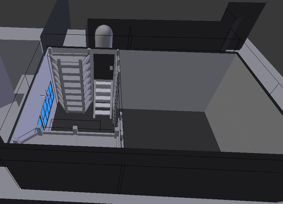
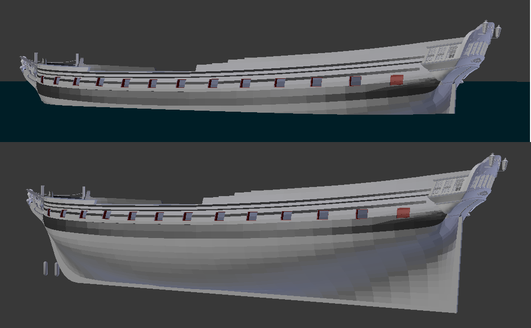
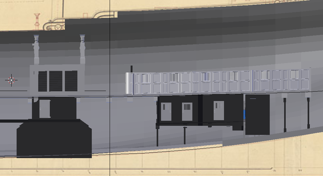
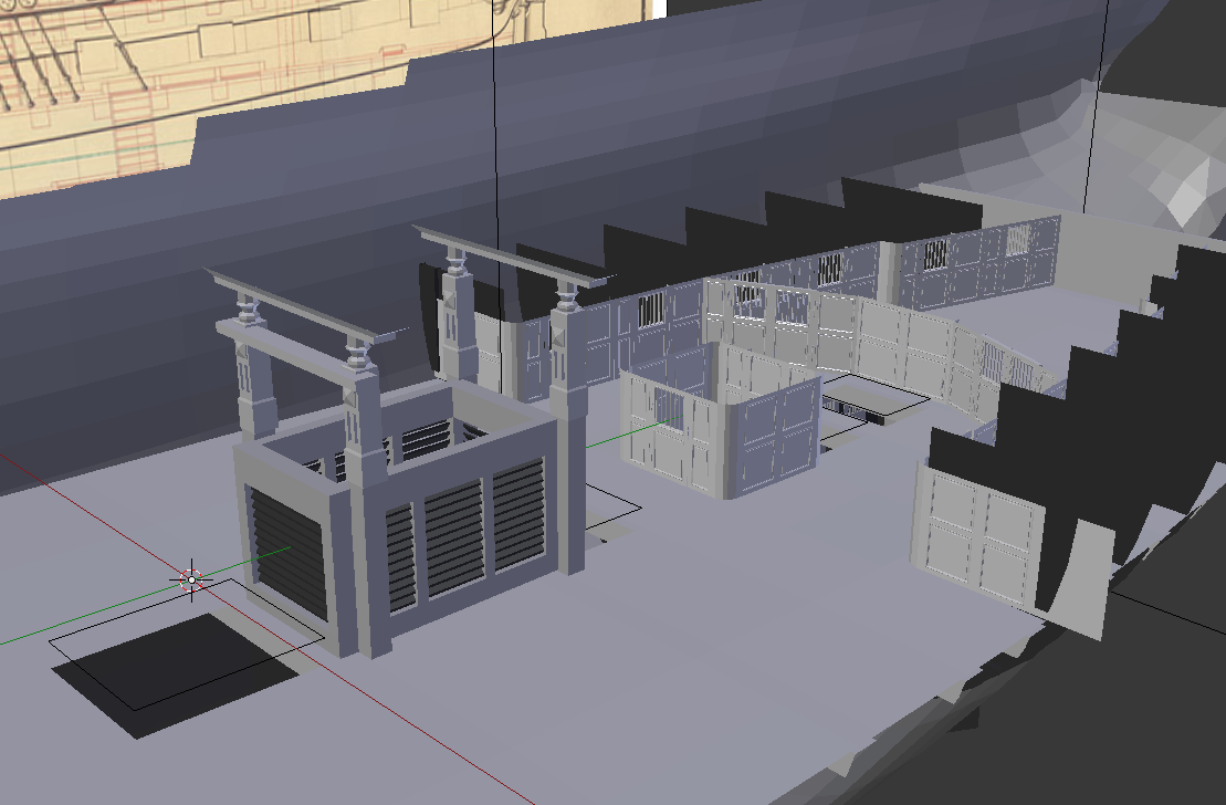
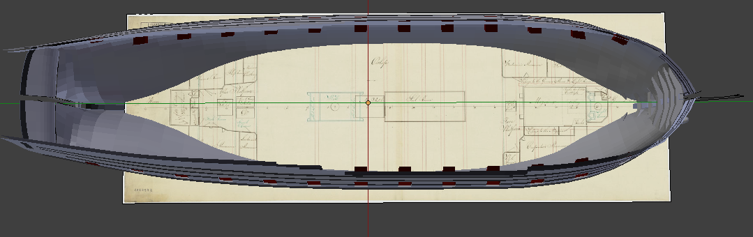
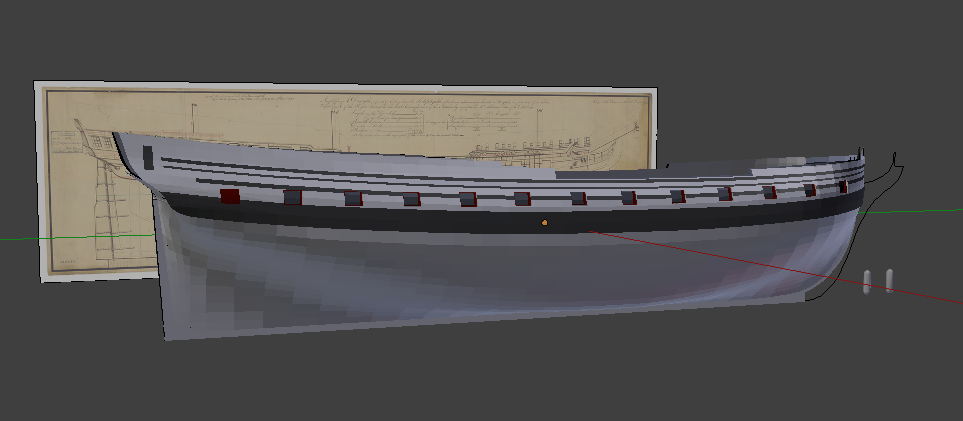
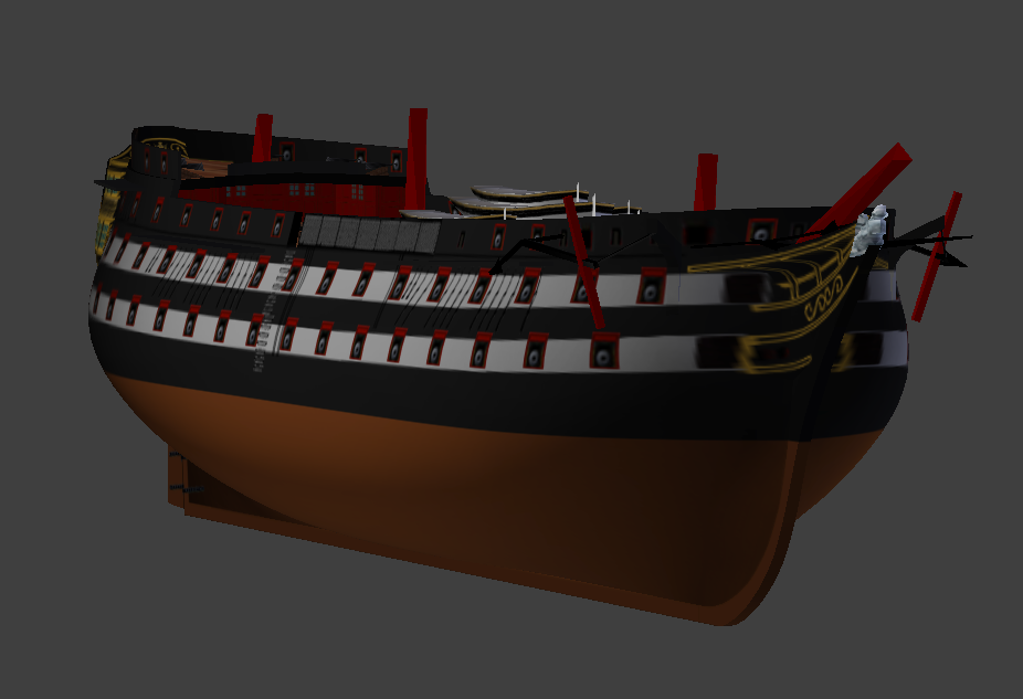
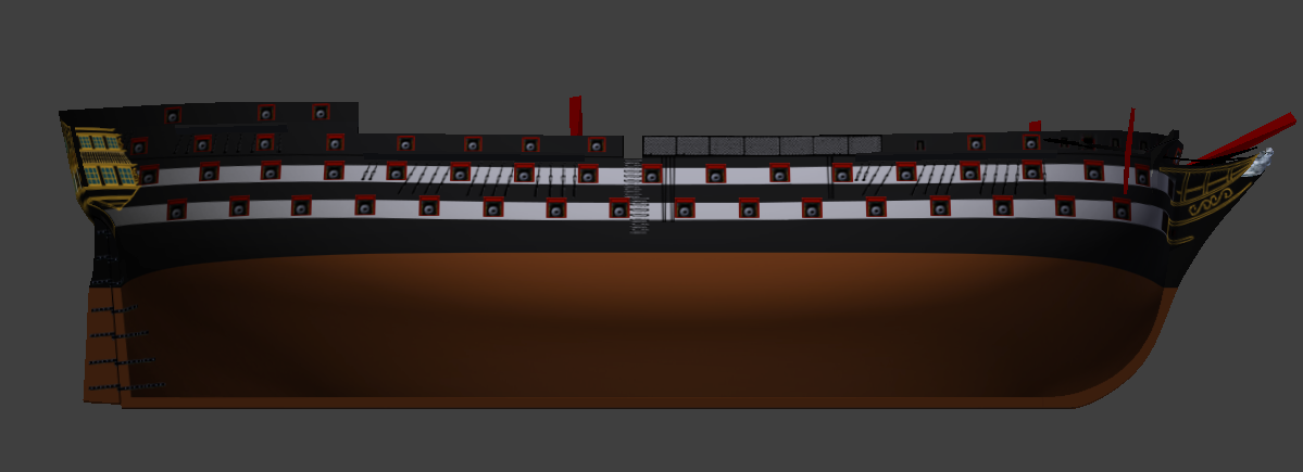
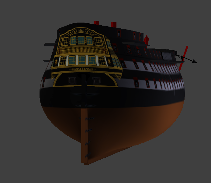
Seeing all the Indefatigable craze going on, I remembered I had an unfinished model of the ship I did back in 2017. It included quite a lot of details, but I couldn't get past the lower deck as I realized there is no way I would handle all the texturing even if I have most of the yet unplaced meshes at hand, and then moved to another game which had very different model requirements. But I thought I could still show it off. The strange grey cylinders are human-size for scale and comparison. And if anyone would want to give it a go, I can probably share the files.


-
USF Confederacy in 3D | Blender
Martes replied to 3DShipWright's topic in CAD and 3D Modelling/Drafting Plans with Software
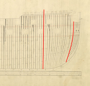
Pair by pair, as each frame on your screenshot is in fact two frames combined together. Note about the cant frames forward. At that time it appears the standard was to use them up to the beakhead (Intrepid - and remember, your ship is +/- the size of a 64 with unarmed lower deck) Or the catheads, which is the same when the bow is round (Constitution) So I would suggest to rotate and compress the pairs depicted forward like this: It would not be 100% accurate (it can never be, we don't know the real parameters of the frames), but it will resemble real structure closely enough.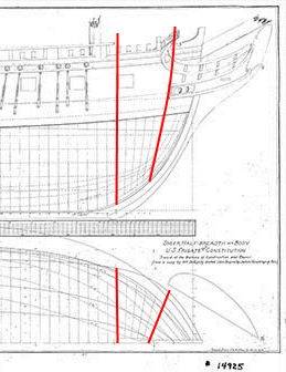
- 107 replies
-
- 1
-

-
- Frigate
- Confederacy
- (and 1 more)
-
USF Confederacy in 3D | Blender
Martes replied to 3DShipWright's topic in CAD and 3D Modelling/Drafting Plans with Software
If Constitution is of any reference, it appears that she has a) cant frames, British style, combined with b) very densely positioned frame pairs, French style, but with almost no spaces between them And, again, if I remember correctly, the British considered Chesapeake "overbuilt for her size", meaning she had even more wood than a British frigate of similar size would be composed of. North America had no shortage of wood, but in several, especially early, cases it was just not seasoned enough and prone to rot. In short, I tend to think that the frames you have on the plans (if they have any connection to real structure _at all_, since they look as based on British "as taken" plan, and the British did not record the plan stations as correlated with actual frame positioning, rather simply measuring the shape of the ship at certain distances from the perpendiculars) represent pairs (i.e should be divided to two different, but adjacent structures), shown with pairs between them omitted for modelling purposes. Additionally, note that Harold Hahn himself writes in his book 'Ships of the American Revolution and their models' that his plans are highly stylised, primarily in intention to build models faster and for aesthetics. This leaves the question of hull ends. Because the spacing between the cant frames is also totally unrealistic and has to be, unfortunately, completely reworked - either referencing British contemporary models or (if you find it) a structure from Constitution. Also, note that Hahn's reconstruction has also economized on the transoms: comparing to both to British examples and the Constitution.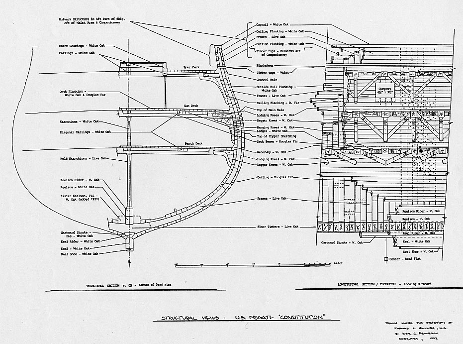
- 107 replies
-
- 1
-
-
- Frigate
- Confederacy
- (and 1 more)
-
USF Confederacy in 3D | Blender
Martes replied to 3DShipWright's topic in CAD and 3D Modelling/Drafting Plans with Software
Just a little bit. But there is a manner of making framed models with omitting one or several of the frames each iteration, so it may be a little dangerous to fall for that and take that as the real structure. And it's best to notice early. Also, IIRC, the term "main frames" refers to the pairs of frames in British structures, and in that sense all the frames in French structure are "main". The single frames are called "filler frames". But the composition of the two frames in the pair is different. One would have a single floor extending to both sides, the other would look like your last screenshot. Although I am not sure you want to go that deep into the structure- 107 replies
-
- 1
-
-
- Frigate
- Confederacy
- (and 1 more)
-
USF Confederacy in 3D | Blender
Martes replied to 3DShipWright's topic in CAD and 3D Modelling/Drafting Plans with Software
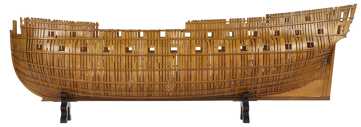
If by using the term "main frame" you mean each gap is filled by a secondary frame it is possible. Also, each frame is not solid and consists of several parts, main or not. If not, however, consider two factors. First, here is an example of contemporary British frigate (the Triton of 1773), which was considerably smaller: https://www.rmg.co.uk/collections/objects/rmgc-object-83032 Or a contemporary British 64-gunner (a ship of a comparable size): https://www.rmg.co.uk/collections/objects/rmgc-object-66486 The French framing differed in having no cant framing on the ends (they were all vertical) and having each pair placed together (and not 2-1-1-2 or 2-1-1-1-2 as the British did). And look in the thread here. https://modelshipworld.com/topic/33702-frames-on-early-18th-century-french-ships/ Even the French construction in very extreme cases had a ratio of 2:1 wood:space. Usually it would be between 4:1 and 5:1. Your model shows 1:1. Even brigs did not have such a light structure. Is the room-and-space parameter known for the Confederacy, just in case?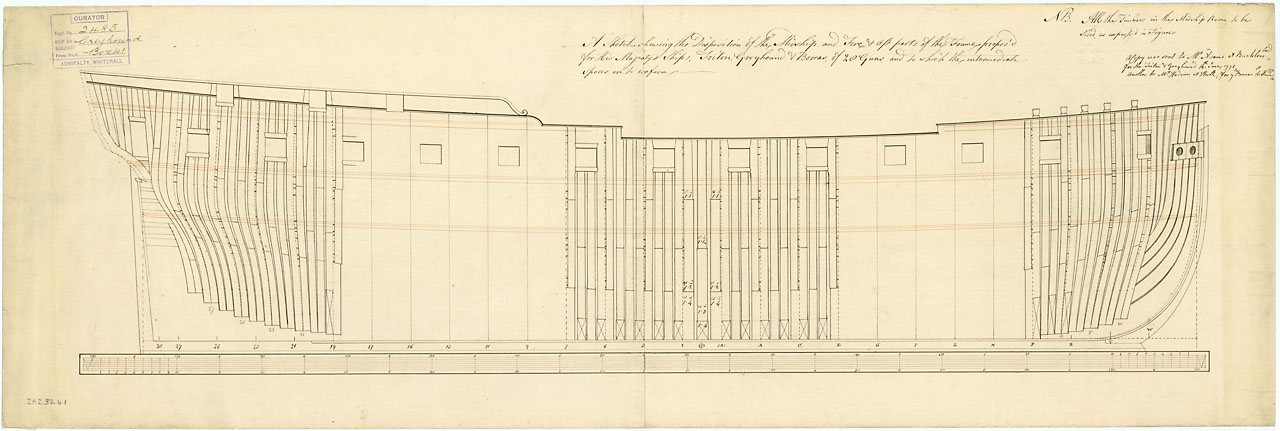
- 107 replies
-
- 2
-

-
-
- Frigate
- Confederacy
- (and 1 more)
-
USF Confederacy in 3D | Blender
Martes replied to 3DShipWright's topic in CAD and 3D Modelling/Drafting Plans with Software
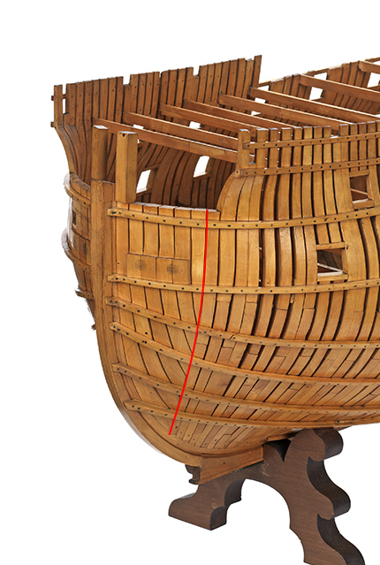
Are you absolutely sure about the frame structure? Do those frames, depicted on the plan, represent single frames or pairs, and are you sure there should not be another frame between them that was omitted for model style purpose? I have seen at least one model of the Confederacy that shows very different set of frames: Taken from here: https://www.shaffers-ships.com/usf-confereracy.html The structure depicted here is British style, with pairs separated by filling frames. It may be possible (I don't know) that the ship could have been built by French style, where there are only pairs separated by slightly wider gaps, but it is very unlikely to be as you have on your model now.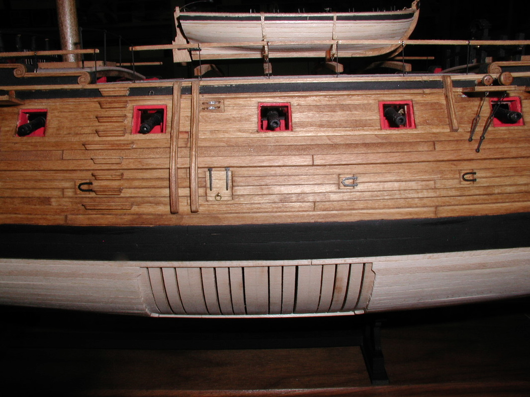
- 107 replies
-
- 2
-
-
- Frigate
- Confederacy
- (and 1 more)
-
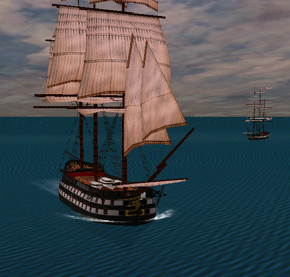
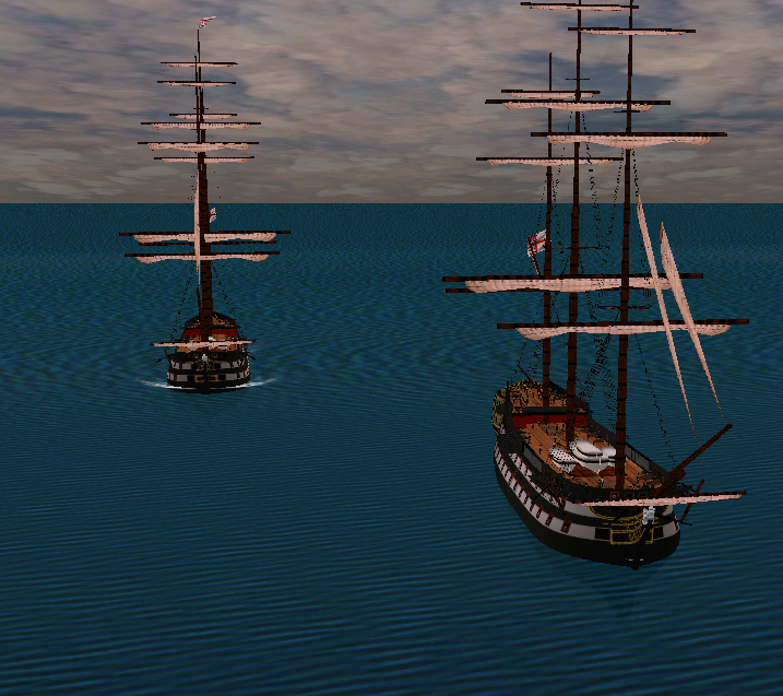
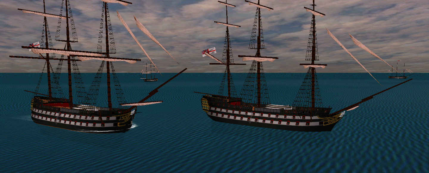
And sailing test:

-
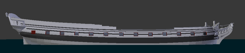
Finished yet another iteration of Cambridge - the same fix of the fore part, more or less, that was applied to most of the ships already, with various little adjustments to head rails and texture. If more detailed testing will not reveal serious deficiencies, it will be possible to begin backporting the hull to make a new version of Christian VII... And possibly, something else.
-
Mathew Baker's early concept of ship hull design, ca. 1570
Martes replied to Waldemar's topic in Nautical/Naval History
I wonder how peer-review system passed a reconstruction that does not provide a clear comparison to the original and did not attempt to compare 3d meshes of both. -
USF Confederacy in 3D | Blender
Martes replied to 3DShipWright's topic in CAD and 3D Modelling/Drafting Plans with Software
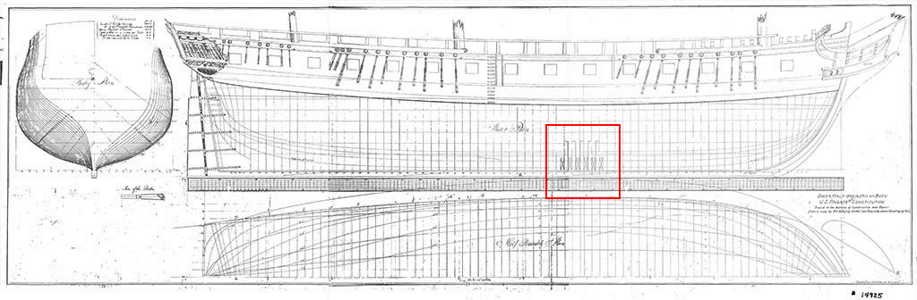
RMG has a set of deck plans, should you need them, and an original lines taken off her. https://www.rmg.co.uk/collections/object?vessels[0]=Confederate (captured 1781)- 107 replies
-
- 1
-
-
- Frigate
- Confederacy
- (and 1 more)
-
2nd rate London 1656 – the art of the shipwright
Martes replied to Waldemar's topic in Nautical/Naval History
@Richard Endsor, As an initiator, in a sense, of this thread - as it was I who suggested to @Waldemar to look into this plan, I feel an obligation to reply. When we saw your interest in the topic we were delighted and hoped that - knowing you were a leading expert in the field and working on the subject - you may provide some information that you possess but which have eluded us, the ship's timbers and their sizes, for once, or anything regarding reconstructing the profile. Were you reluctant to share this information, you could have left us to play our games of numbers and lines, and stayed a celestial being, an author to be cited and referenced. You could have waited until we ran - if indeed we ran - into a wall and deliver the coup-de-grace. We had a plan B exactly for this event. And if we didn't run into a wall - well, there would be a one more version of reconstruction, and the final comparison would still depend on whether any parts of the original ship's structure are raised and measured, provided they survive that long. We had a discussion here not very long ago concerning the difference between the reconstructed replica of the Hermione (which was built referencing a contemporary treatise by Morineau) and the remains of the real ship, which case is even more striking as the remains of the ship were measured and known before the replica project began. In my worst nightmare couldn't I imagine to see a thread degrading into a comment referring to somebody's knowledge of any language or personal traits with an impossible amount of condescending as a final argument in a dispute over existing and readable texts, even with understanding this comment is fueled by an obvious conflict of interest. I sincerely hope that the above comment will be removed and forgotten. -
2nd rate London 1656 – the art of the shipwright
Martes replied to Waldemar's topic in Nautical/Naval History
@Mark P, @Richard Endsor I would also like to remind the initial premise of the reconstruction here was to extract as much data as possible from those plans, being a first-hand period document, and to verify whether it is possible to recreate a feasible hull on their basis. @Waldemar in our correspondence told me, that it is much easier to rely on general procedures of the period, the general dimensions and possibly the midship section, and produce a typical period ship that would conform to the known dimensions, and that he could do it very quickly. That potential reconstruction would probably have had fixed floor radii and most of other characteristic design features of the period, as we know them. Would it resemble the London? Only the wreck can tell, if any frames are excavated or at least measured. However, that was not what he intended, because it would effectively discard the same first-hand document we are looking at. Somebody, somewhere around 1660's has put quite an effort into creating this plan. We already understand that there is no way a the hull was built exactly as it is depicted, there are too many bumps and inconsistencies, and yet, we would first want to catalogue them, filter through and understand what is a genuine feature that could have been done then and what is a graphical error or inaccuracy of the author. After all, what do we know of Captain John Taylor? If he was a navy captain, does that mean he was rather an amateur and not a professional shipbuilder? Could he have used some non-mainstream techniques with little regard to the heresy he committed? -
2nd rate London 1656 – the art of the shipwright
Martes replied to Waldemar's topic in Nautical/Naval History
I will put the table of those measurements here. And, from Winfield. Antelope Woolwich Dyd. [M/Shipwright Christopher Pett] Dimensions & tons: 120ft 0in keel x 36ft 0in x 14ft 0in. 828 (by calc, 827 88/94) bm. London Chatham Dyd. [M/Shipwright Capt. John Taylor] As built: 123ft 6in keel x 40ft 0in x 16ft 6in. 1,050 bm. As girdled: 123ft 6in keel x 41ft 0in x 16ft 6in. 1,103 (1,104 26/94 by calc.) bm. The ships are very close in length, but the Antelope is considerably narrower. Leaving aside the question of floors for the moment, what can the measurements of Antelope tell us about the London? How the timber and room would change if the length remains almost the same, but the ship is made wider? The rake of the stem and the stern? I remember the arc of the stem could be usually dependent on the ship's breadth, so would the stem on London differ considerably from that of the Antelope?
-
2nd rate London 1656 – the art of the shipwright
Martes replied to Waldemar's topic in Nautical/Naval History
Both Winfield (British Warships 1603-1617) and Franklin (Navy Board Ship Models 1650-1750) say the model is closest in dimensions to the Antelope of 1651. It was also compared to Speaker and Fairfax, as far as I remember. The model of Riksapplet is indeed very sharp and round, especially for a 3-decker, but there is at least one more Swedish ship, probably made by Sheldon's son or grandson Swedish ship Sparre, by Sheldon A 1037 VIII https://www.sa.dk/ao-soegesider/da/billedviser?epid=17149179#208027,39521509 That displays very similar hull to the model. The ship is either the Sparre of 1724 or even later of 1748, so it definitely can't serve as a direct reference, but the design recycling is interesting in this case. Other early 18th century ships signed by Charles or Gilbert Sheldon are very different.
-
2nd rate London 1656 – the art of the shipwright
Martes replied to Waldemar's topic in Nautical/Naval History
I feel compelled to note that the Bellona is a very controversial example here, herself being based on the lines of the French L'Invincible (1747) (Winfield, British warships 1714-1792), and is not the most typical representative of the native British design school (as opposed to the practice of incorporating foreign designs) of the 18th century. That the plans are not ships building plans is obvious - they carry post-Restoration decoration, while Van de Velde portraits show the Commonwealth style and arms on the stern. Some details, like the form of the taffrail, are very similar. Still, for some reason they were drawn as they were, and they contain some system and probably some hints to the original, that would be somewhat wasteful to disregard outright. As I mentioned earlier, it would be much easier if we had the lines of the Antelope model to analyze. But, alas, we don't, so we try to examine the possibilities. -
Drawings of ship flags of different states. XVIII c.
Martes replied to greenstone's topic in Nautical/Naval History
One could suppose that some Cromwellian rogues, but since 18 and 19 carry the same inscription it is more feasible that those were flags of the ships that switched over to William of Orange. -
2nd rate London 1656 – the art of the shipwright
Martes replied to Waldemar's topic in Nautical/Naval History
@Richard Endsor, thank you very much for looking in and welcome! Indeed, at this stage we used the 3D mesh to simply verify the feasibility of the hull and spot problematic places. And there are lots of them. The premise of this undertaking was the hope that, unlike later ships in 18th century, a ship of this period can be "recalculated", if a method of the design was determined, and utilizing @Waldemar's familiarity with period methods to reconstruct the profile and, eventually, the appearance of the ship. For London we know the most basic dimensions (Winfield, and it is a separate question of where he got them and if there is something more there) - the keel length, the breadth and depth in hold. Initially it was hoped to derive the missing dimensions of the ship - rake of the stem and the stern, room and space, distance between stations and the length of middle body from this set, however we soon understood it to be impossible due to the inconsistencies that plague these plans. My suggestion at that stage was to look at the closest reference we have - the 1650s model from RMG that is generally identified as the Antelope and while narrower is very close in size and time of construction to the London. We have photos of the model and some measurements in the Franklin book, including measured parameters of the stem, stern and R&S, however it is not entirely clear how they would relate to those on the London, which is only slightly longer, but considerably wider. I suppose it would be of enormous help if there were lines taken off that model, but I am unaware of such a set in existence. -
The state of the French Navy, July 1st, 1691
Martes replied to Martes's topic in Nautical/Naval History
And it was first rate intel then. Also that the real lion's share is dedicated to midshipmen (pages and pages of them!) is understandable given their relative numbers, but still very funny. -
Orders issued by the Duke of York 1661–1668
Martes replied to Waldemar's topic in Nautical/Naval History
And that's done as well. https://modelshipworld.com/topic/33926-album-of-drawings-of-cannons-and-mortars-from-archive-of-peter-the-great/ -
Album of drawings of cannons and mortars Mostly mortars, but I spotted at least one naval gun.
-
- 3
-
-
Orders issued by the Duke of York 1661–1668
Martes replied to Waldemar's topic in Nautical/Naval History
Eugen @greenstone, I can't express enough thanks for pointing us to those documents. -
The state of the French Navy, July 1st, 1691
Martes replied to Martes's topic in Nautical/Naval History
I wonder what Gerard would say. -
Orders issued by the Duke of York 1661–1668
Martes replied to Waldemar's topic in Nautical/Naval History
Browsing the same folder, I saw two very interesting documents relating to Sweden (naval articles and a general report on the country) and a book on French naval signals (all for 1690s), but they are written in more elaborate and dense font and are slightly more difficult to read.