iMustBeCrazy
-
Posts
974 -
Joined
-
Last visited
Content Type
Profiles
Forums
Gallery
Events
Everything posted by iMustBeCrazy
-
 Not by me, I'm certain that it's two tanks with the coolant to port of the fuel tank. It has a conical bottom like the fuel tank and is probably 'tear drop' shaped (like an aluminium mast). It shares the fuel tank mount. Meanwhile I've found a new puzzle.
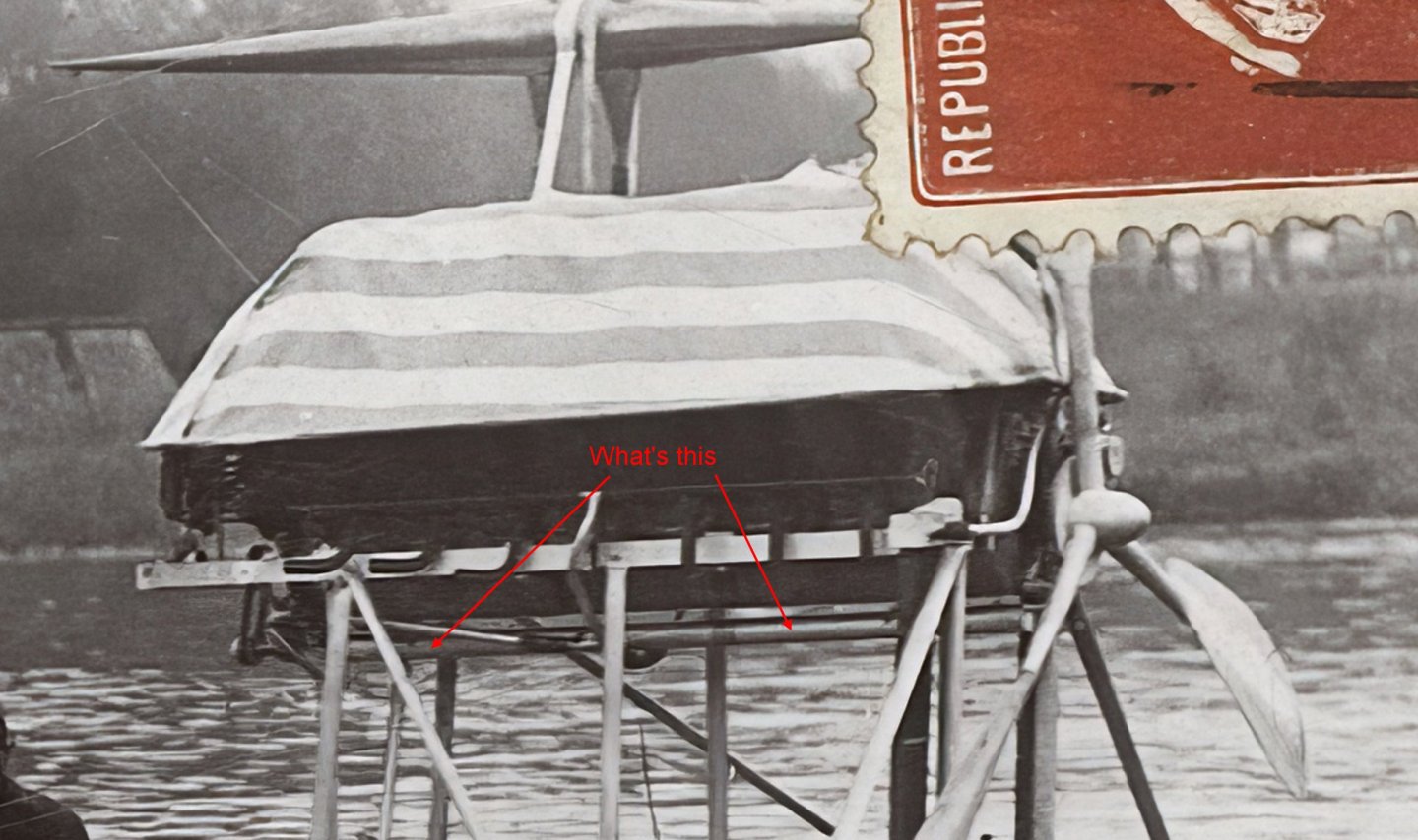
- 288 replies
-
- 1
-

-
- Santos Dumont No. 18
- hydroplane
- (and 1 more)
-
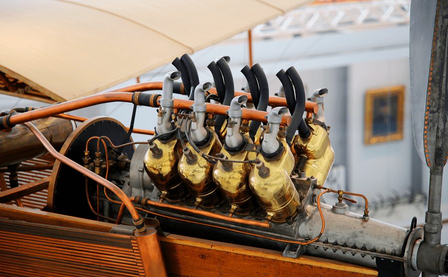
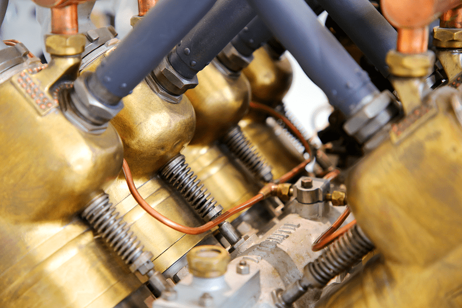
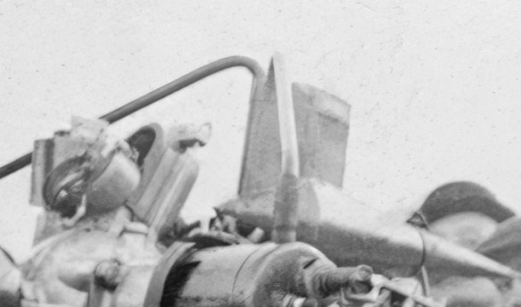
I'm not sure but I think what you're seeing might be the body of the device, it's really hard to tell. Anyway, I can't find a definite oil pump on any of the Antoinette engine images, it is probably internal. See post 241. The pic above I interpret Lets start from scratch, there is a journal (a path for fluid) through the block running the length of the engine above the camshaft. It is always seen with a copper pipe attached. This would have to be for fuel or oil. I now believe fuel. Near the connection there is an aluminium block with a brass 'nut', I think this is a regulator. In the above pic the pipes also go to the dash, I'm guessing to a priming pump so as to get fuel to the cylinders before the fuel pump is turning. This is still common in aircraft. There is a tap into the journal mid engine (V8) with lines going (apparently) to the injectors. Which again suggests fuel. Why am I bringing this up? Well with the magneto on the aft end of the engine there is no room to get pipe into the journal at that end so either all the fuel plumbing is external or the fuel now goes in the front and perhaps the fuel pump is there too. But then what is the belt driven device aft?
- 288 replies
-
- 3
-
-

-
- Santos Dumont No. 18
- hydroplane
- (and 1 more)
-
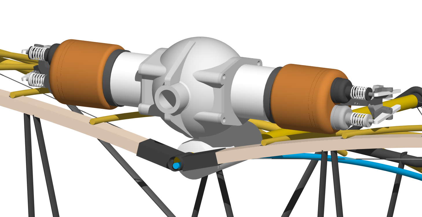
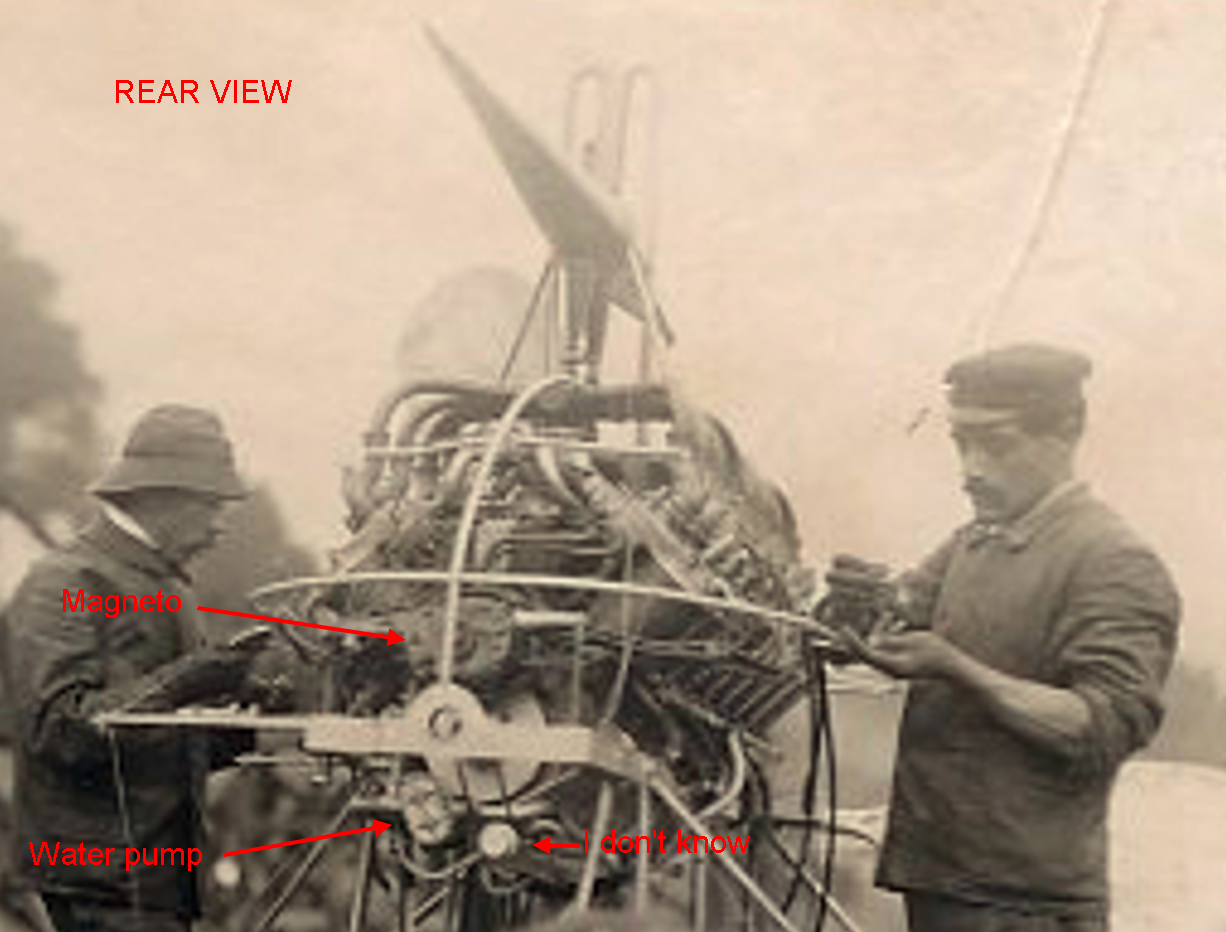
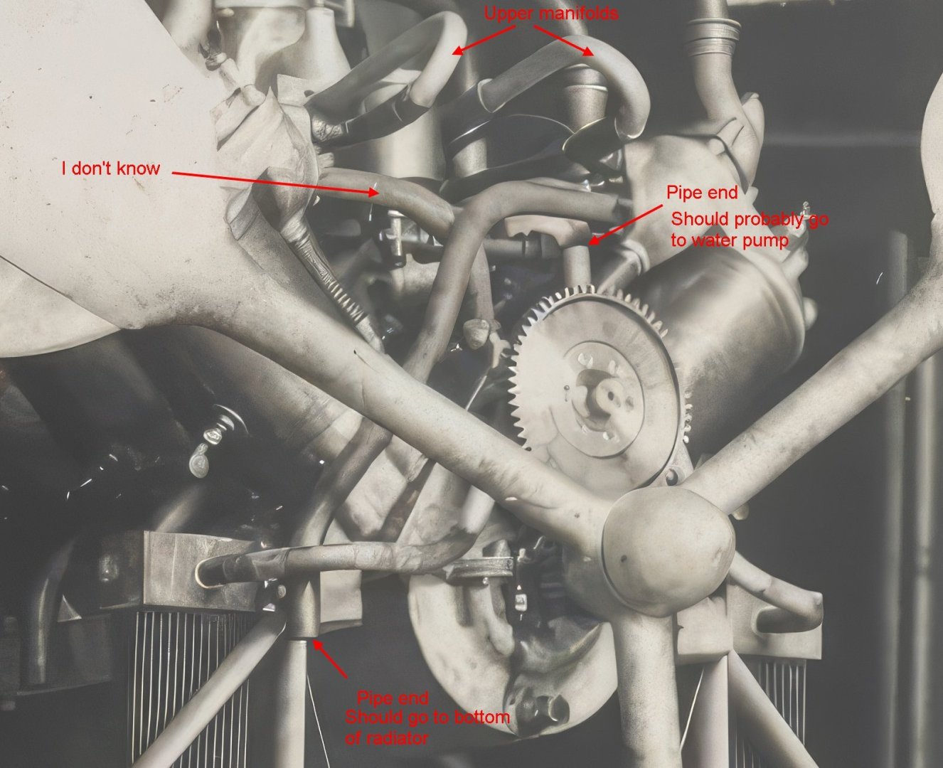
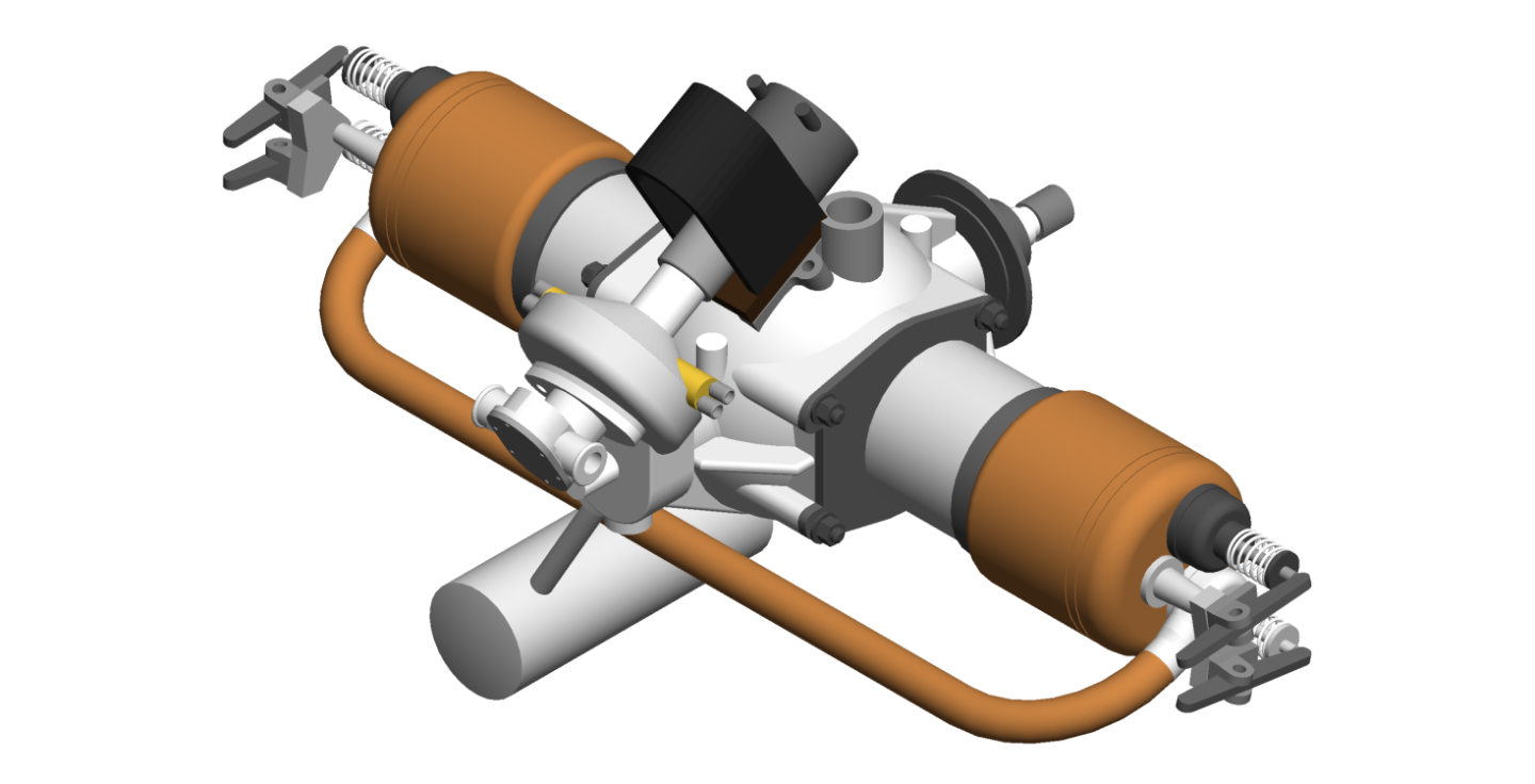
I thought so but boy do I have a curved ball for you, what if they turned the whole engine around? It was designed to be able to be run backwards. Lets ignore that for the moment and stick with what we know. On the aft end we have a magneto, a water pump and another belt driven device (probably a fuel pump but we don't know). The magneto must be gear driven using the same (type and size) gears as the camshaft. On the forward end we have a possible pulley (?) driving possibly another pulley (??) driving another device. We cannot see crank or camshaft gears but they may still be there. Coolant (most likely) comes down from the header tank into the 'Y' manifold, into the top of both radiators, out the bottom of the radiators to another 'Y' manifold, along the hull to the back of the engine and up to the water pump, out both sides of the water pump to the lower cylinder manifolds, out the upper cylinder manifolds to two 'T' joints (a guess) and back to the header tank via the two bent pipes.
- 288 replies
-
- 3
-
-
- Santos Dumont No. 18
- hydroplane
- (and 1 more)
-
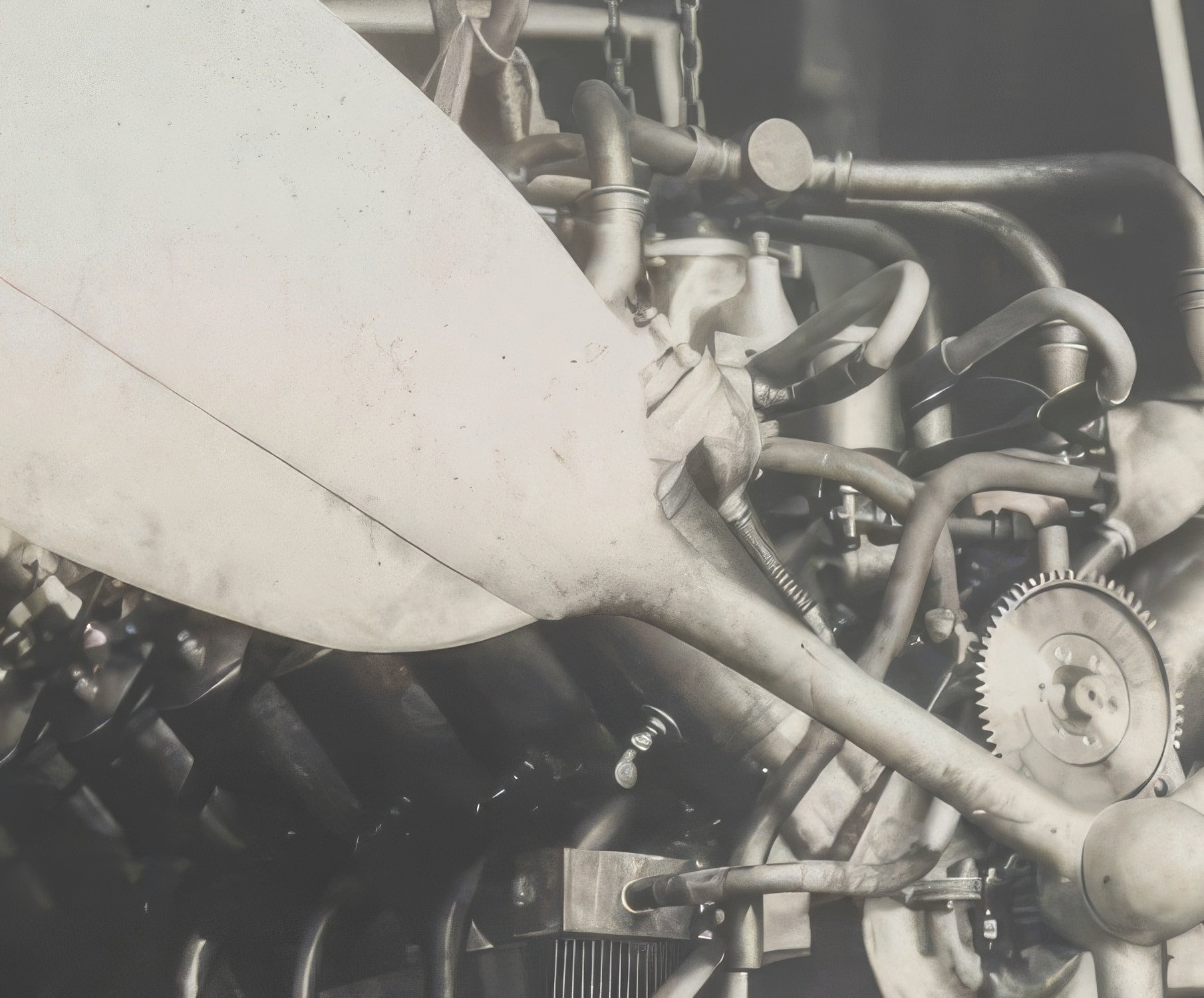
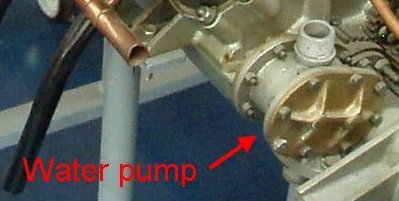
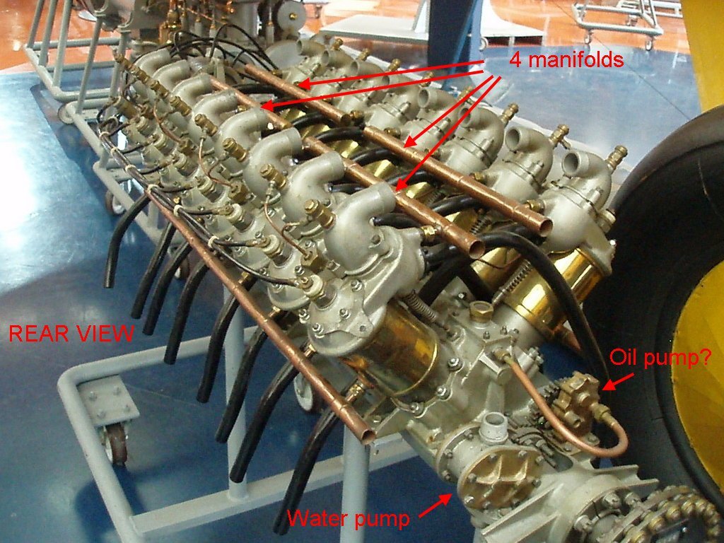
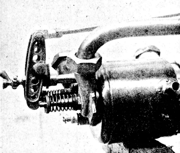
Keith, these are crops from pics in post 221. I think it's fairly obvious from the outlet that this is a water pump, not fuel or oil. And the double cross pattern here is the same but it has been rotated so the outlets are horizontal.
- 288 replies
-
- 4
-
-
- Santos Dumont No. 18
- hydroplane
- (and 1 more)
-
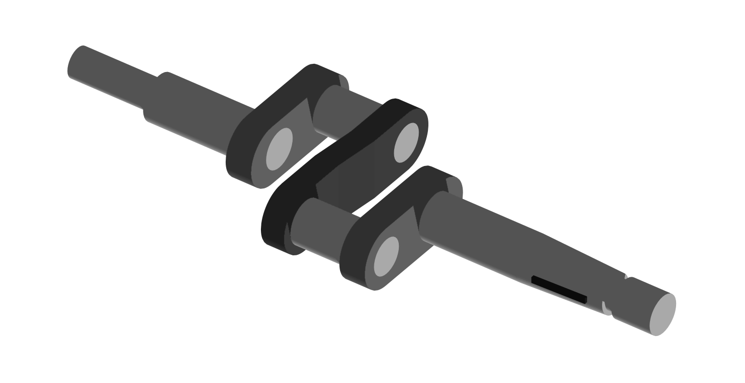
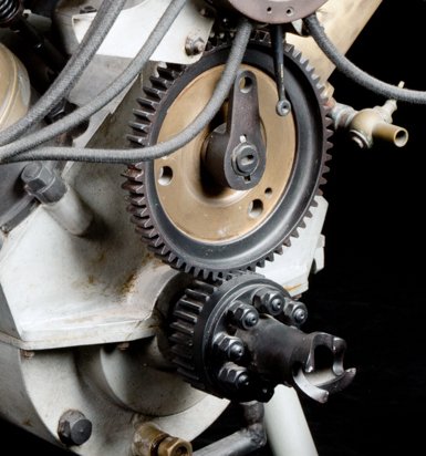
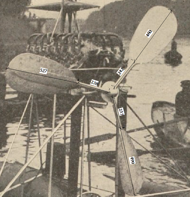
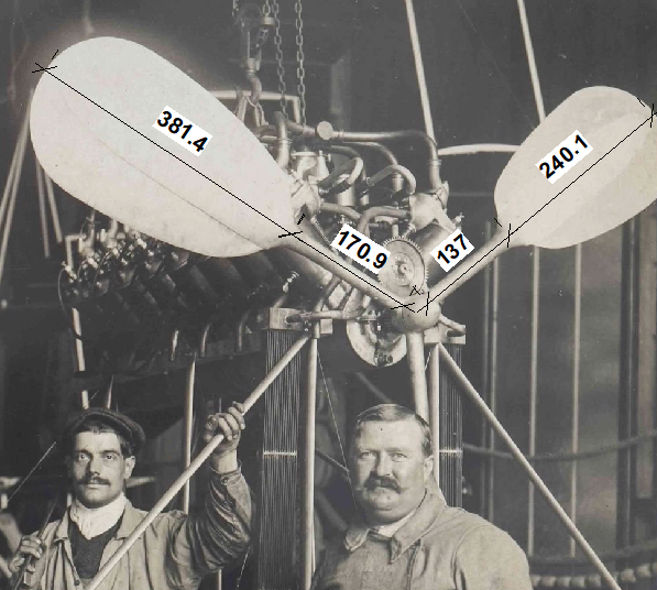
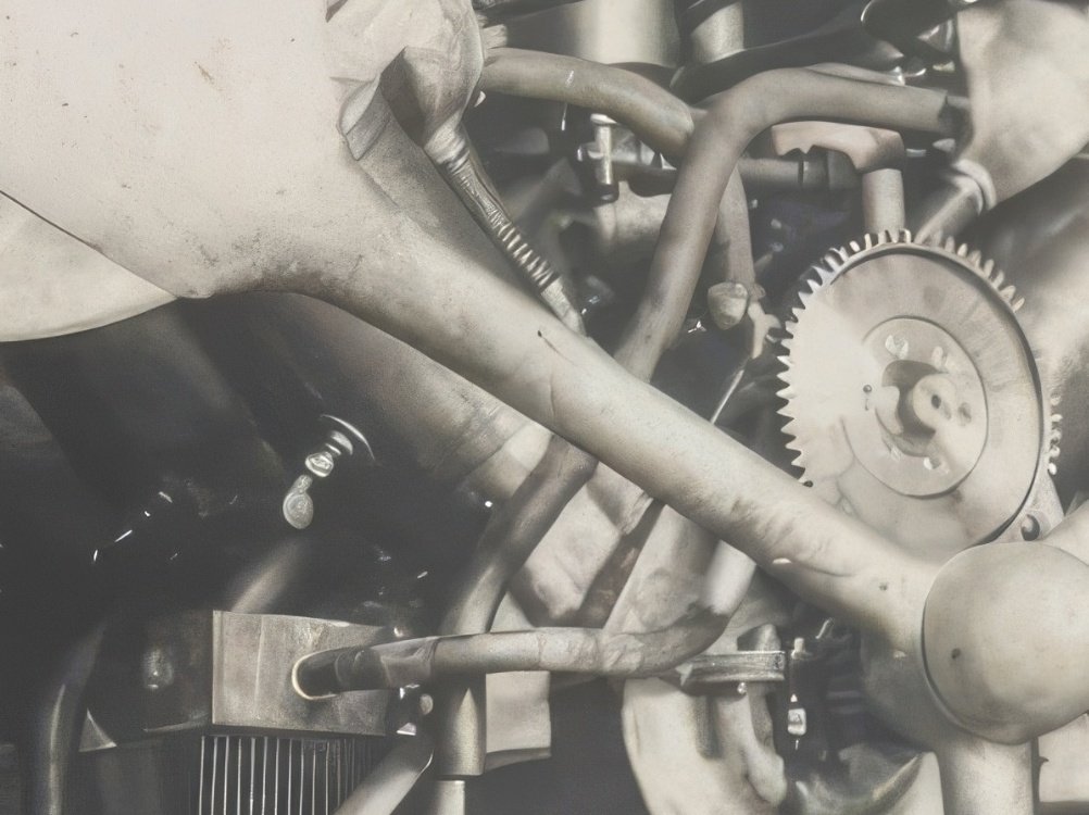
Now, bear with me I've just woken up so I might get some of this wrong. The prop, I think, is driven directly off the crankshaft. The gear on the crankshaft has 32 teeth, the gear on the camshaft has 64 so the ratio is 2:1. It's a four stroke. It's easier to see in this V8 pic (and you can count a quarter of the teeth on the v16 and get the same result): Then I found this: The Antoinette engines used a primitive type of direct fuel injection. A belt-driven fuel pump at the rear of the engine fed fuel into a small reservoir (injector) located above each intake valve. So it needs a fuel pump as well as an oil pump and a water pump. Or is my 'oil pump' a fuel pump, I still need to check but I don't think so yes it probably is.
- 288 replies
-
- 4
-
-
- Santos Dumont No. 18
- hydroplane
- (and 1 more)
-
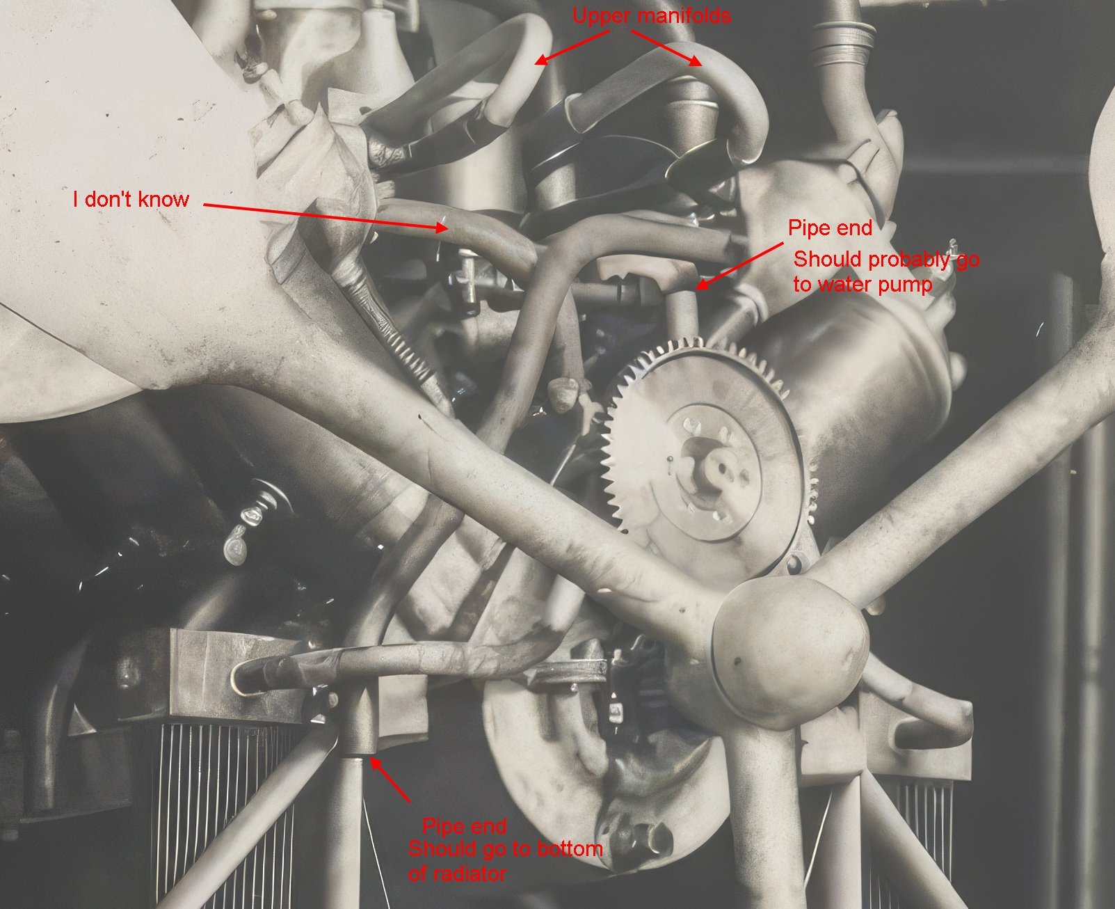
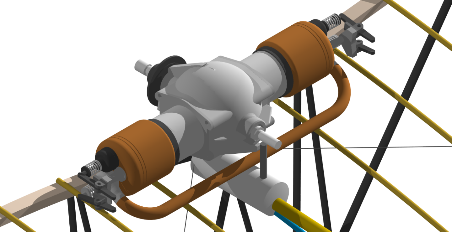
Ok, I think this nails the water pump. The "I don't know" may be a booster pump given the extent of the plumbing and the height of the header tank. Maybe. The ?? (post 215) may be a gear driven oil pump moved to the front. Just a guess. The top pipe from the radiator 'Y" manifold could go to the water pump or the lower cylinder manifolds. In the top pic it looks like the water pump feeds the lower cylinder manifolds. EDIT: Sounds like I mostly agree with William.
- 288 replies
-
- 5
-
-

-
- Santos Dumont No. 18
- hydroplane
- (and 1 more)
-
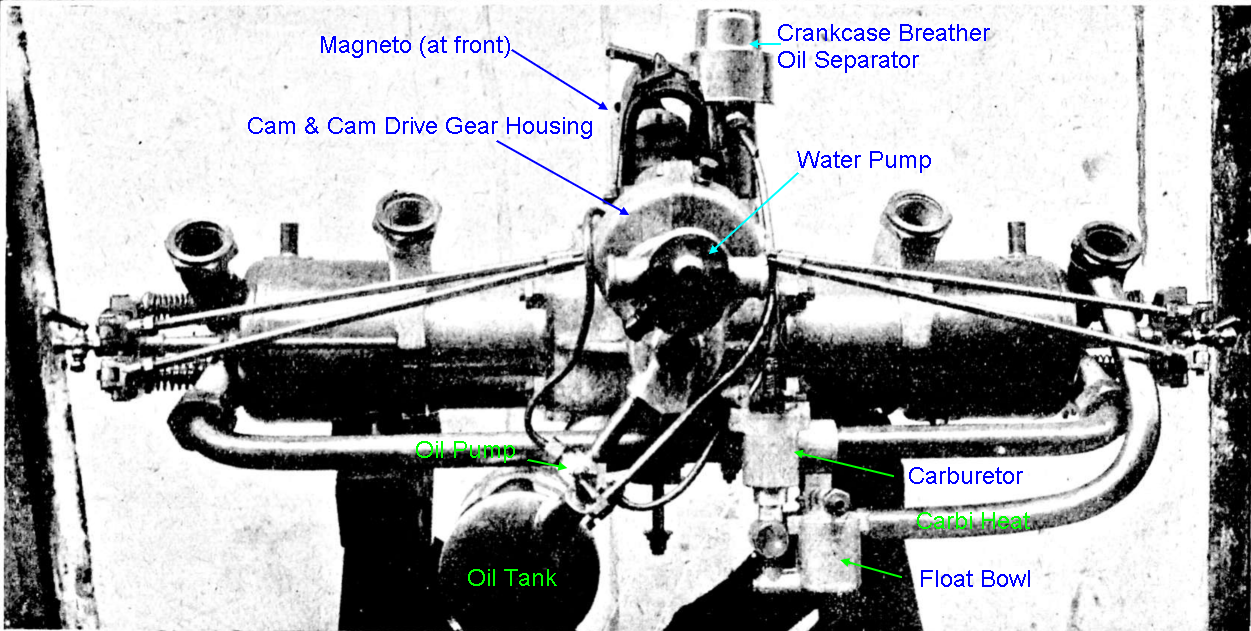
The red arrow is pointing to the camshaft drive gear, note that the pipes to the radiator join behind it and go up then bend back to run along the top of the block.

- 288 replies
-
- 5
-
-
- Santos Dumont No. 18
- hydroplane
- (and 1 more)
-
Greg, The Demoiselle had a coolant header tank there so I suspect that's it. So, from the header tank through the radiators to the water pump through the lower manifold through the cylinder jackets to the upper manifold and back to the header tank. Demoiselle below.
- 288 replies
-
- 4
-
-
- Santos Dumont No. 18
- hydroplane
- (and 1 more)
-
I've been trying to nut out what's going on up front, and failed. Having the water pump aft was normal on the V8 and having the magneto aft helps keep it out of the spray. But what ? and ?? are I have no idea. There's not much space for ? to be a pulley and ?? could be gear driven so why would you need a pulley?????

- 288 replies
-
- 5
-
-
-

-
- Santos Dumont No. 18
- hydroplane
- (and 1 more)
-
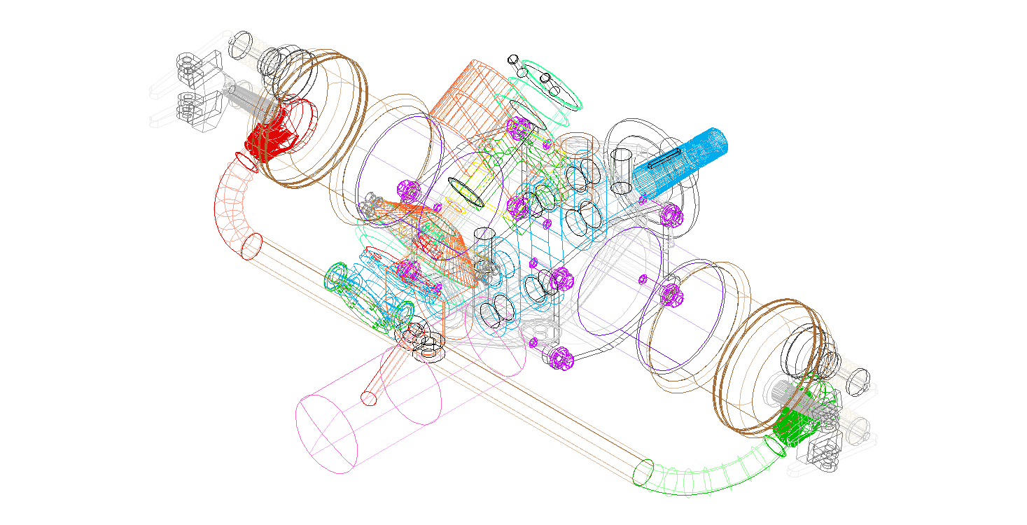
The progress is a little more visible this time, I've added a cam housing, cam shaft and cams, cam followers, a water pump and a magneto. I've also moved the oil tank to the side and done some stupid things we're not going to talk about.

-
You could try gluing the brass to a backing then when finished cutting soak it in the appropriate solvent to remove it.
-
Not much visible progress, I built the intake manifolds and piping (you can see one, rear right, in the second last photo. And that's a real crankshaft: I found some more photos of a 40hp Darracq, very close to the one used. I was wondering how they moved the Oil Tank and Pump to clear the bamboo longeron, now I know.

-
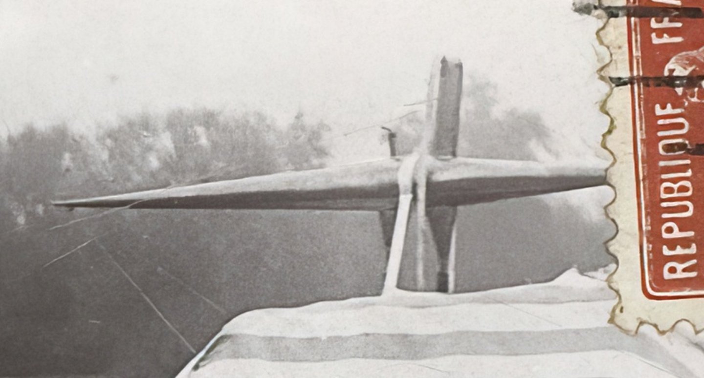
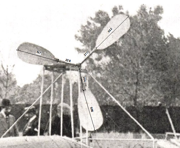
Ok, I've averaged 4 photos: They come out as: 2.1:1 2.0:1 2.0:1 2.1:1 So I'm guessing 2:1. These photos are not to scale so don't read anything else in the numbers. Greg, note the clearance between the prop and the hull in the last shot when considering the diameter.
- 288 replies
-
- 8
-
-
- Santos Dumont No. 18
- hydroplane
- (and 1 more)
-
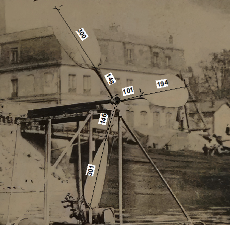
Greg, I think you're pretty close. My estimation is that the shaft should come out to about the cylinder heads and that the blades are two and a bit (two and a half?) longer. The diameter is most probably a nice round metric number. Actually most of the measurements would be.
- 288 replies
-
- 6
-
-
- Santos Dumont No. 18
- hydroplane
- (and 1 more)
-
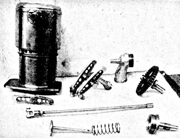
More detail on the engine:

-
Some more progress on the engine today. It should look like this (note, rear view): It currently looks like this:


-
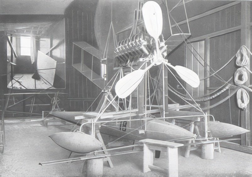
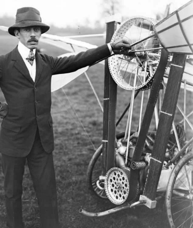
And still not as scary as a 1909 Demoiselle.
-
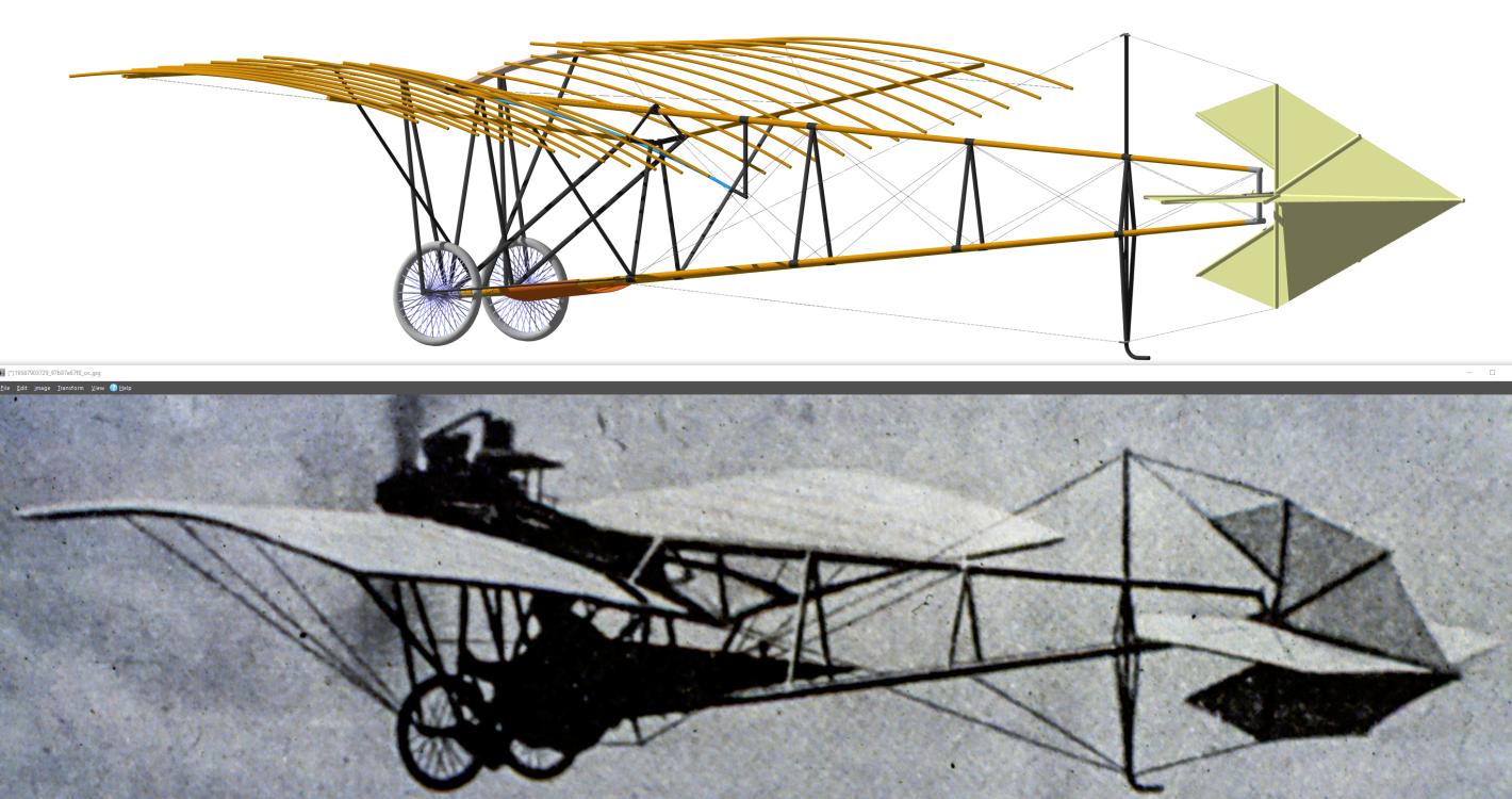
Here we go again..... The Demoiselle came in three main variants, the 19, the 20 and the 21. I believe Santos-Dumont was only involved in the 19 and 20 while other third parties made versions of the 20 and 21. Santos-Dumont made changes on the fly, the 20 started with a V8 but was refitted with a two cylinder horizontally opposed engine slightly more powerful than the 19. Anyway, it's confusing. I'm drawing what I think was the latest 20 which I'm designating (unofficially) the 20d. It won't by any means be perfect but should be reasonable: The main bit are mostly done, just everything else to do. And I've started on the engine.


-
That's a very good question, somewhere in the 20's.
- 288 replies
-
- 3
-
-
- Santos Dumont No. 18
- hydroplane
- (and 1 more)
-
This was the first version of the '20' with the V8 between his legs (well almost) I think I'm doing the last version of the '20' with the water cooled twin (which I'm just starting drawing, luckily there's a patent with drawings). He re-used everything. It makes it really hard to work out if a photo is earlier or later.
- 288 replies
-
- 4
-
-
- Santos Dumont No. 18
- hydroplane
- (and 1 more)
-
Greg, I hadn't noticed this before: Anything look familiar?
- 288 replies
-
- 6
-
-
- Santos Dumont No. 18
- hydroplane
- (and 1 more)
-
Maybe. I have to move in the next few months so I'm not starting anything non digital. If/when I do it would probably be in 1:8 to match Camel and SE5a kits I have.
- 288 replies
-
- 6
-
-

-
- Santos Dumont No. 18
- hydroplane
- (and 1 more)