


iMustBeCrazy
-
Posts
967 -
Joined
-
Last visited
Content Type
Profiles
Forums
Gallery
Events
Everything posted by iMustBeCrazy
-
 I haven't fully thought this out but perhaps bore out these disks to take a shaft for alignment? Then your supports could support the shaft and be standardised, some fixed to a base some moveable to wherever you're working.
- 288 replies
-
- 4
-

-
- Santos Dumont No. 18
- hydroplane
- (and 1 more)
-
Thanks Tony. Biggest worry at the moment (apart from everything else) is the MDF bulwarks, I have to fair one side unsupported so that I can plank or line them so they are supported to fair the other 🤷♂️
-
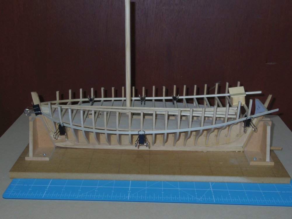
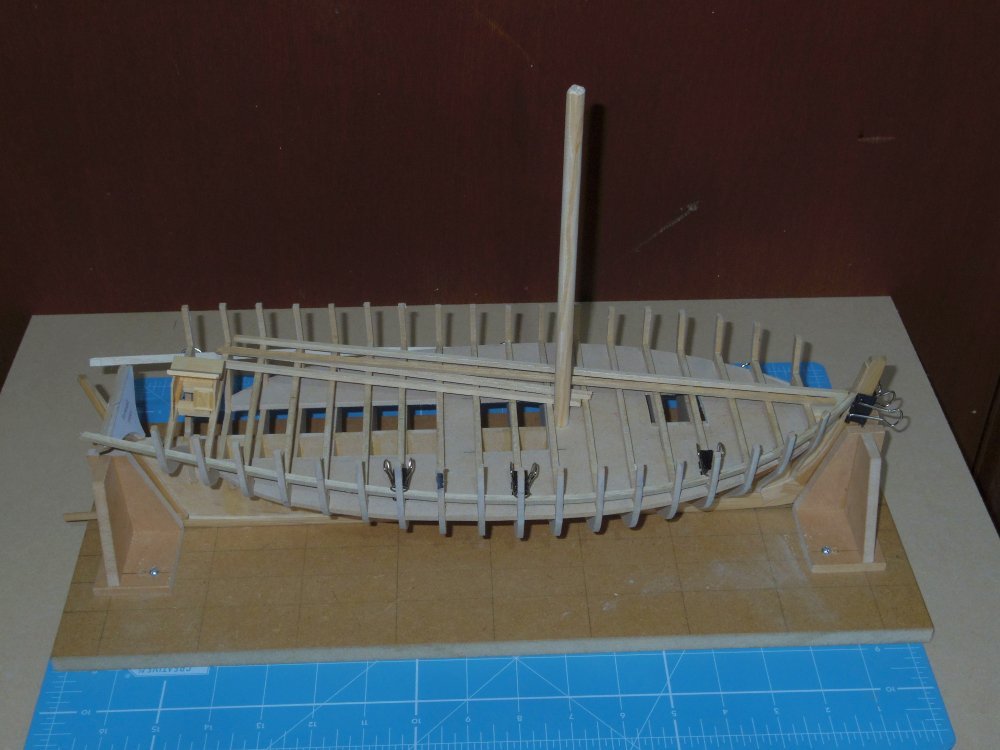
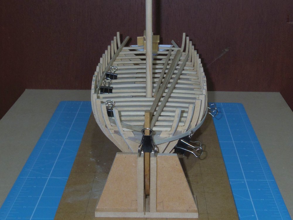
Some progress, in a forwards direction Build board built, 'deck beams' bent, everything glued up to and inc the 'deck beams'. Wale being test fitted (again), waterway being worked out (they're next I think). After the waterways it'll have to be the counter timbers, that will be fun.
-
First issue with the drawings, moulds 2 and 4 have the labels swapped, 2 should be 4 and 4 should be 2.
-
Hopefully
-
Initial drawings (Ver 1.0) added to post #1.
-
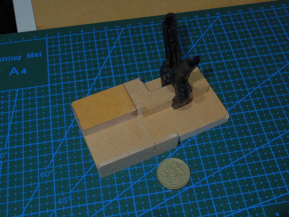
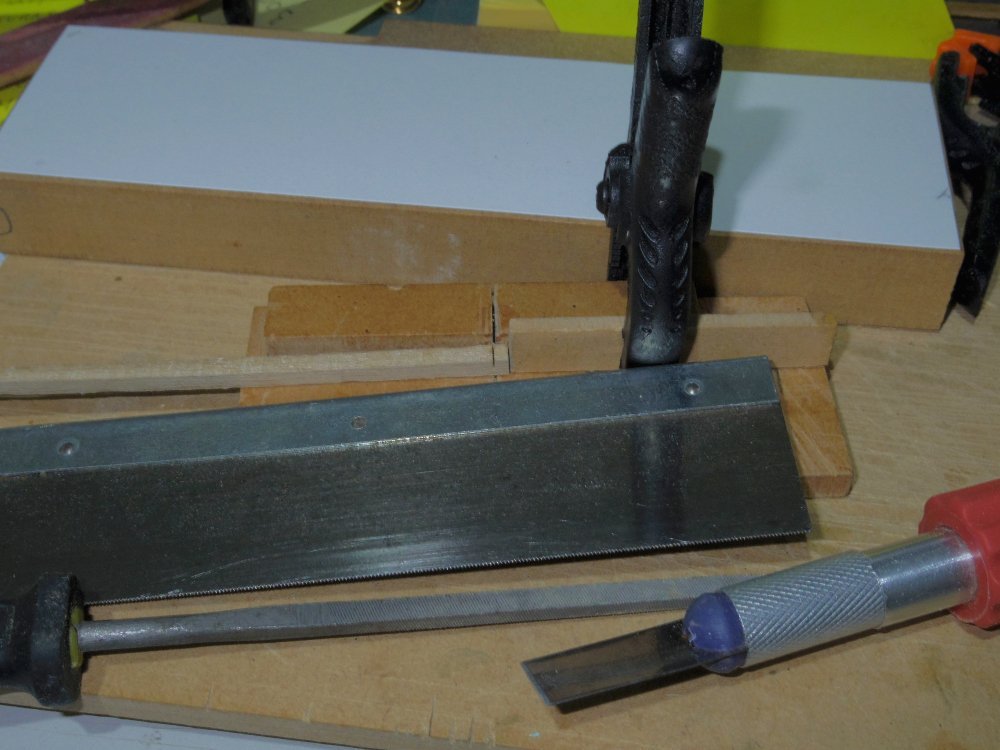
Yes and yes. I used 9mm mdf plus a piece of 3mm. Base is 100x50 big enough to be useful small enough to be handy. The top bits are 25x40 with the right one notched to allow clamping a stop. Everything is just glued in place. Make sure the corners where they meet the saw are square. Glue the left block first and allow the dry then use a straight edge (ruler) and scribe the cut line. Glue the right block using the saw as a spacer and a straight edge to align the blocks, let dry. Glue the 3mm guide and let dry. Cut the guide slot in the 3mm piece. Done. The only things that matter are the squareness of the slots (two sides/corners of each block and the guide) and the alignment of the two blocks. You could do the guide in two pieces using the straight edge to align the left side and the saw the right.
-
And here we have the CrazyCutter MkII
-
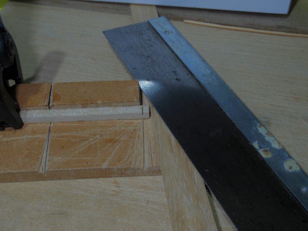
Looking closely at my 'old worn out' razor saw it's actually a pull saw but I like it better as a push saw. 😕
-
A mixture, or some stained some not? Part of the idea is to break up the 'sameness' of the decking.
-
Tim, I use a cutting guide (one sided mitre box) and a razor saw for the cross cut then mostly a chisel blade and a file to remove and clean up the rest. Instead of the chisel blade you could also use the razor saw lying on a spacer. I really should remake the cutting guide with the guide piece twice as deep and twice as high (it's currently 12mm deep and 6mm high).
-
I've finished mine for now, had a couple of issues related to using thicker wood than I had drawn, I should have updated the drawing then I would have picked up the issues.
-
Well that's done for now, I'll decide whether to leave doors/lids open when I actually fit it.
-
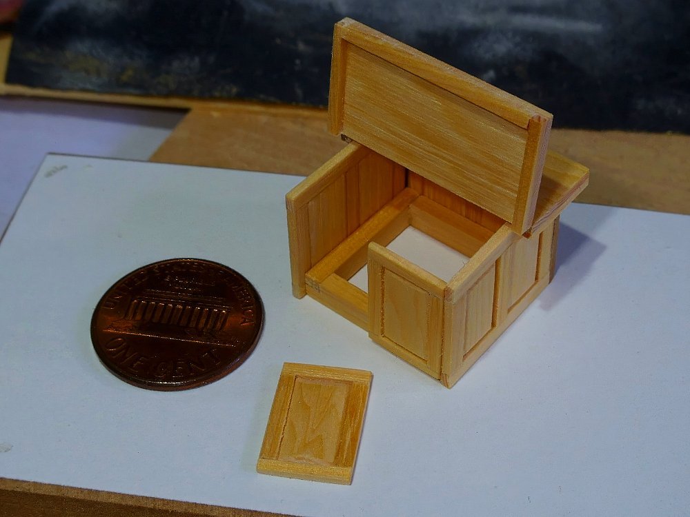
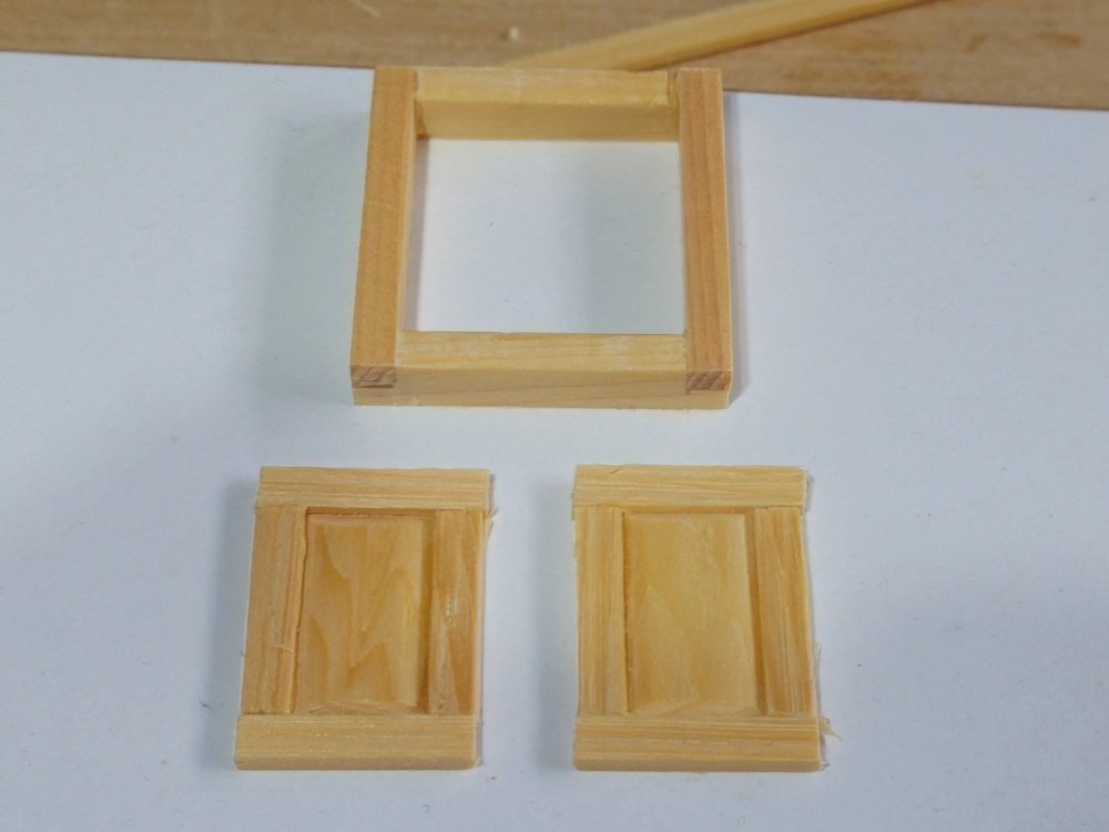
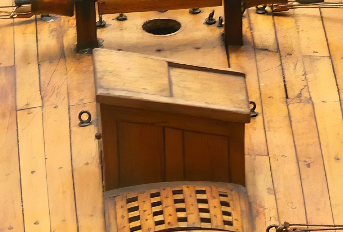
Sorry about the delays. Basically I test fitted a wale and found that a straight plank just wouldn't work, I finally figured that the finer bow messed things up (compared to Cheerful) and that a curve was needed forward. I did that and it fits nicely but I guess the rest of the planking will need similar. I also marked the wales on the drawings but when I made two new moulds the wale didn't quite line up with the marks, probably something to do with the fairing but the stem midships and transom are all good with the wale just laying without any coercion. More on the wale when I get around to planking. Now, Tim is building Speedy, a descendant of Lapwing and has distracted me (see the discussion in his log) so I've started building mine: Just the coaming and doors for the moment, I forgot the obligatory 1 cent coin but the doors are about 15mm high and awaiting the glue to dry before sanding.
-
The hull is quite narrow there, most efficient use of space? Give me an hour.
-
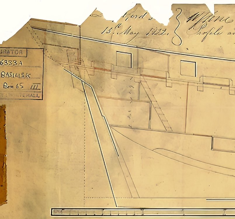
You should be, and I'm sure you will find it indispensable. Meanwhile there's this Vigilant drawing which shows that the companionway may well have sat on the coaming. But after playing around and cutting some wood I've nearly decided the companionway was actually a solid block of wood with the doors (badly) painted on
-
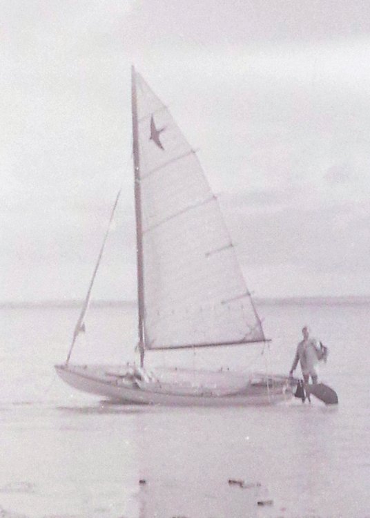
Thanks Mark. No she's an 18' Swallow, designed by (I think) a Sydney dentist.
-
If you edit post #1 you can edit the title.
- 33 replies
-
- 1
-

-
- Bounty Jolly Boat
- Artesania Latina
- (and 1 more)
-
A quick google would suggest that by the early 19th century you could get almost any hinge you could imagine. I think something like this in black or brass:
-
My best guess? I think the aim would be watertight or near to it, this is officer country. You don't want the Captain breaking his leg slipping on a wet ladder. The roof might even be just two very wide boards. As I said, a gutter under the join at the hinge. Probably a half lap where the door meet, the lid covers the top of the doors. But still guesses.
-
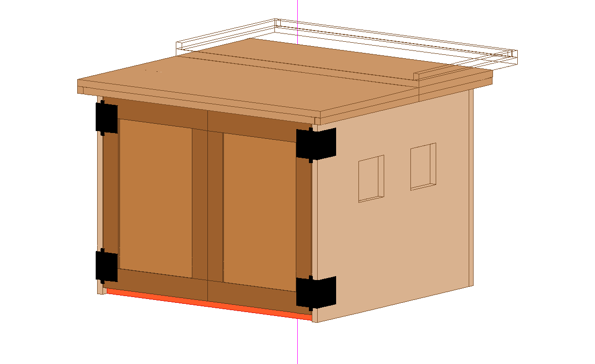
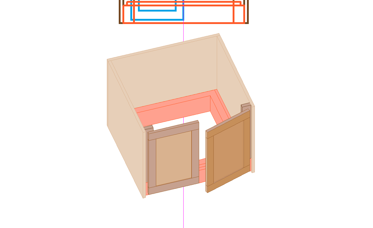
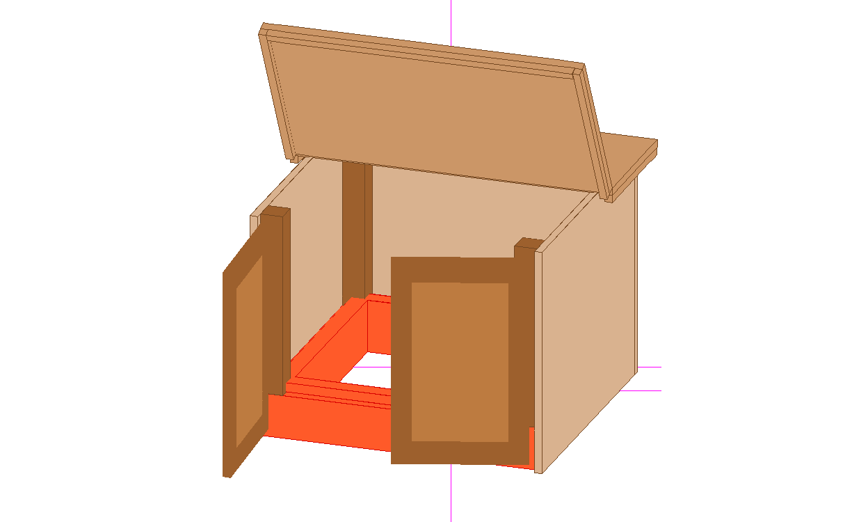
Yes, but it still must be removable. I'm still thinking a flat hinged lid but with the hinge line offset 2 or three inches to port and a drip rail (1" x 1") around the underside of the lid (not drawn yet). Still need the lid, panels on the other side, glass on the forward and aft sides, 3" timbers in all four corners (replacing those 1x3 bits at the doors). Like this:
-
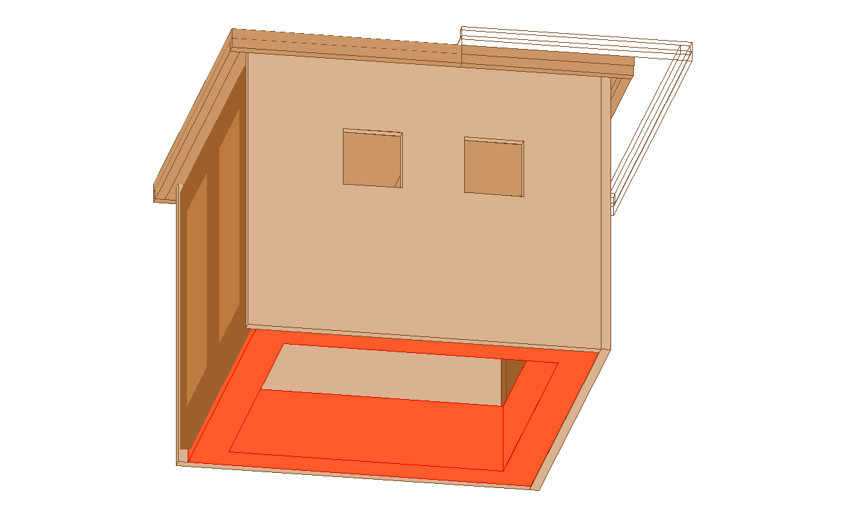
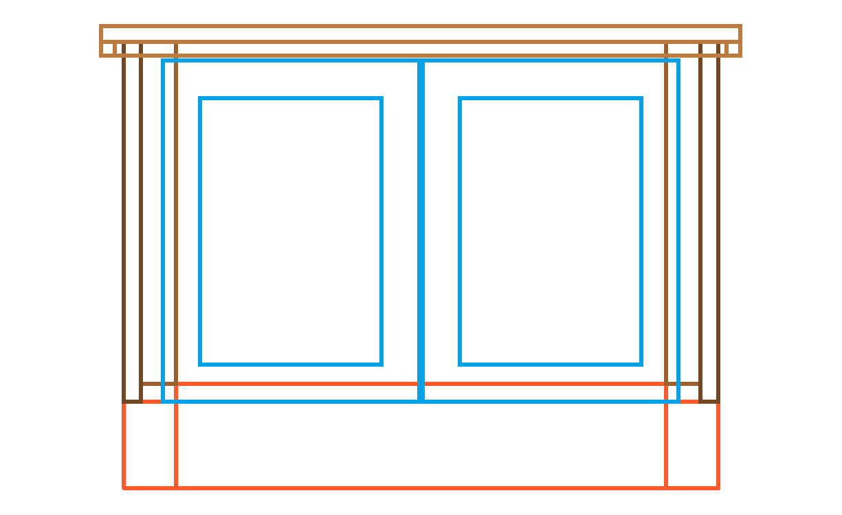
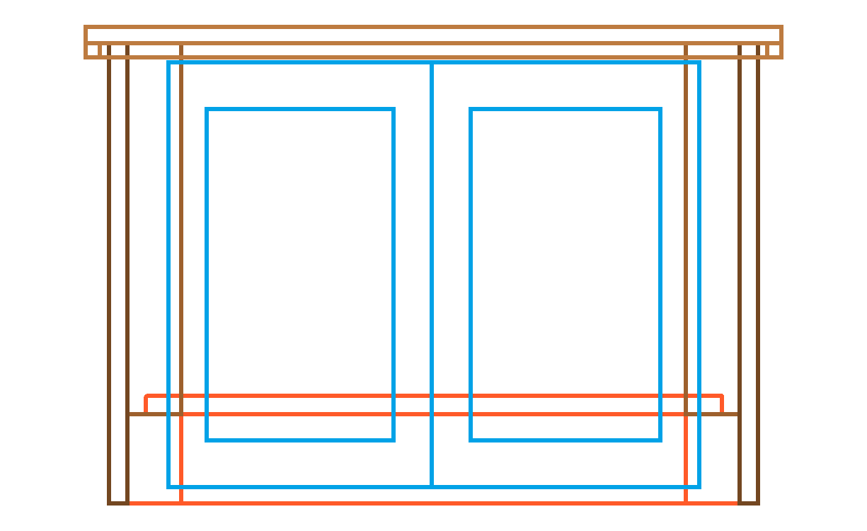
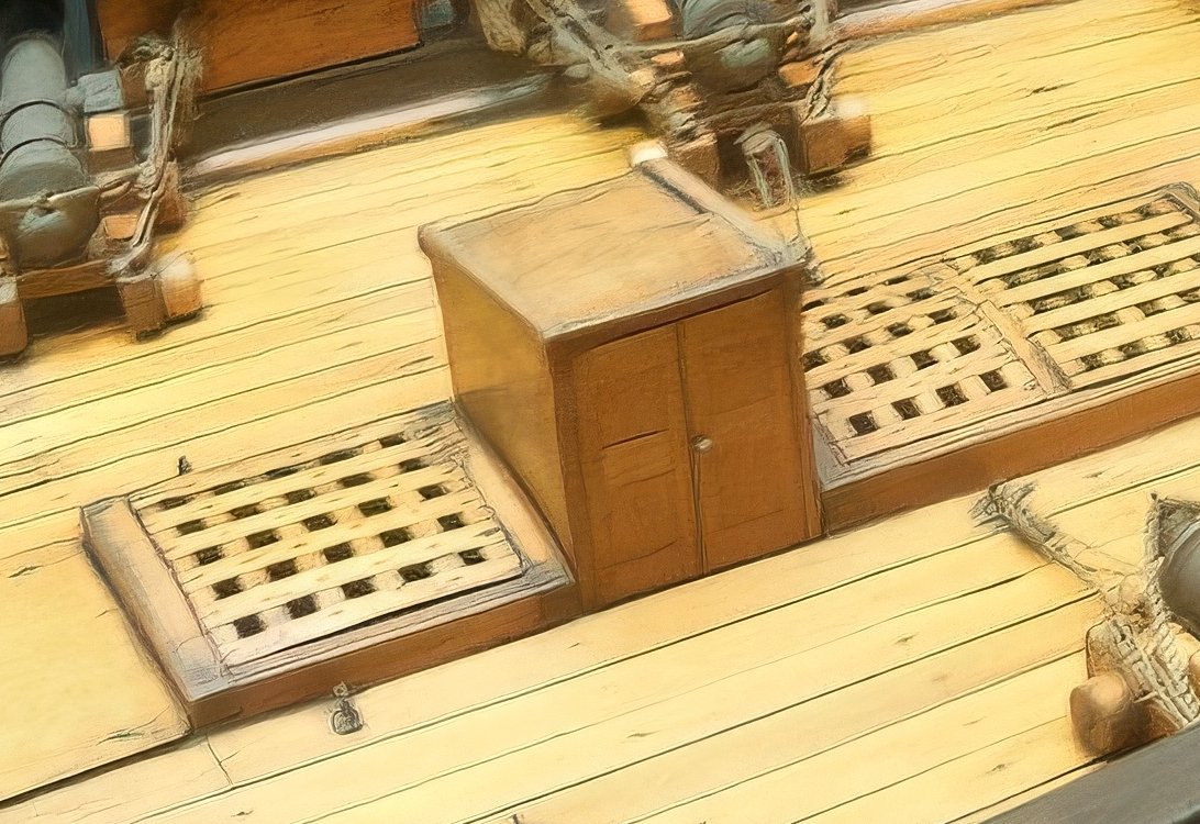
A couple of possibilities, the first built on top of the hatch coaming the other surrounding it. I think the latter is more likely based on drawings and models.
-
This Brig (original photos by Larry Van Es) looks close to me.
-
As I said, I'd just make the whole thing square to the deck. The shuttlecock is sitting against a skylight, the companionway is forward of that and has a sliding roof.
-
ZAZ6430 also shows them on the side and covers Fancy, Kite, Racer and Sprightly. Speedy is also mentioned. The Vigilant class opens aft. Head first like a shuttlecock? I'll do some enlargements of your paintings.