iMustBeCrazy
-
Posts
967 -
Joined
-
Last visited
Content Type
Profiles
Forums
Gallery
Events
Everything posted by iMustBeCrazy
-
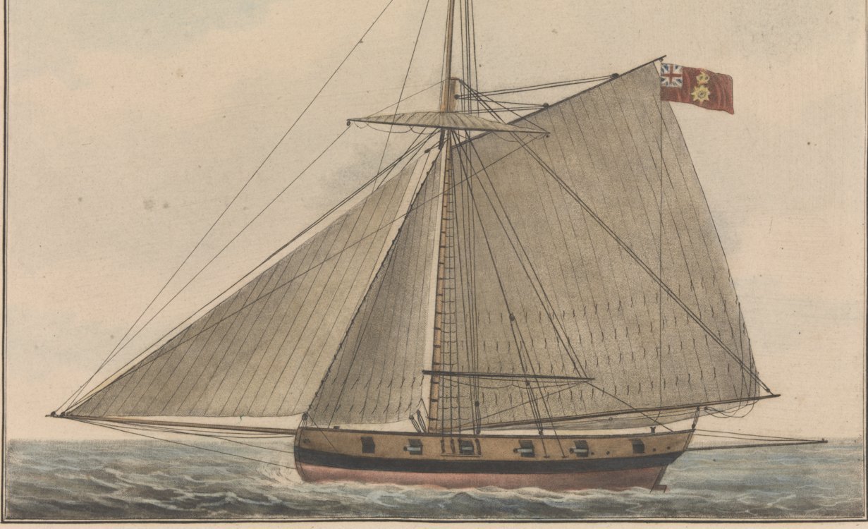
 Pretty good guess, https://www.rmg.co.uk/collections/objects/rmgc-object-15591
 -
Working in Huon Pine makes me cry with every cut, every piece you can buy these days is salvaged. You could try using plane shavings, a thick shaving would be about 0.2mm with very little wastage.
- 288 replies
-
- 4
-

-
- Santos Dumont No. 18
- hydroplane
- (and 1 more)
-
Tim, this is a bit of a tough one. I did a bit of experimental archaeology (masking tape outline on floor) and unless the roof opening is at least 18" (and I mean absolute minium) I would have trouble getting in in a reasonably dignified manner (admittedly I'm not a flexible as a young commander). As it is I suspect the normal method of entry would be to sit on the deck with your legs over the coaming and stand on the ladder two or three rungs down. But contemporary models show you're most likely on the right track. I would suggest it was built over a hatchway with a raised coaming just like the bread room one but with no grating, square to the deck not the keel as drawn, it may slope down to port (or may not) to assist draining, tight joints to reduce leaks, it may have a small gutter under the hinge, it may be glazed on at least one side. Alternatively it may have a half sliding roof. Of course I may be completely wrong. This might give you an idea as to how small it is although this one is lower than that on Speedy:
-
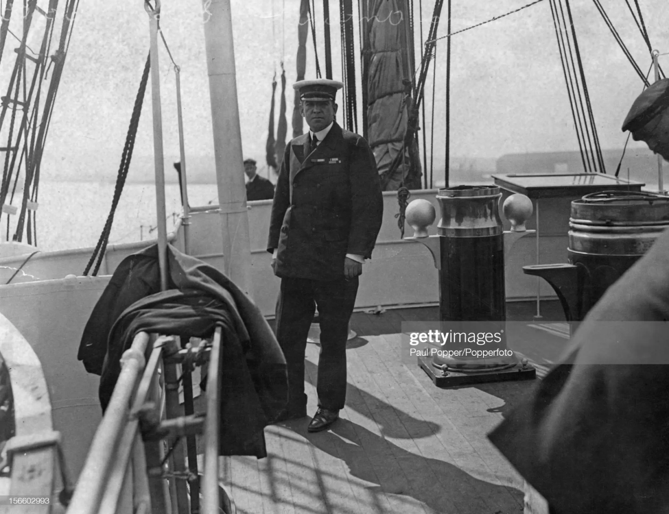
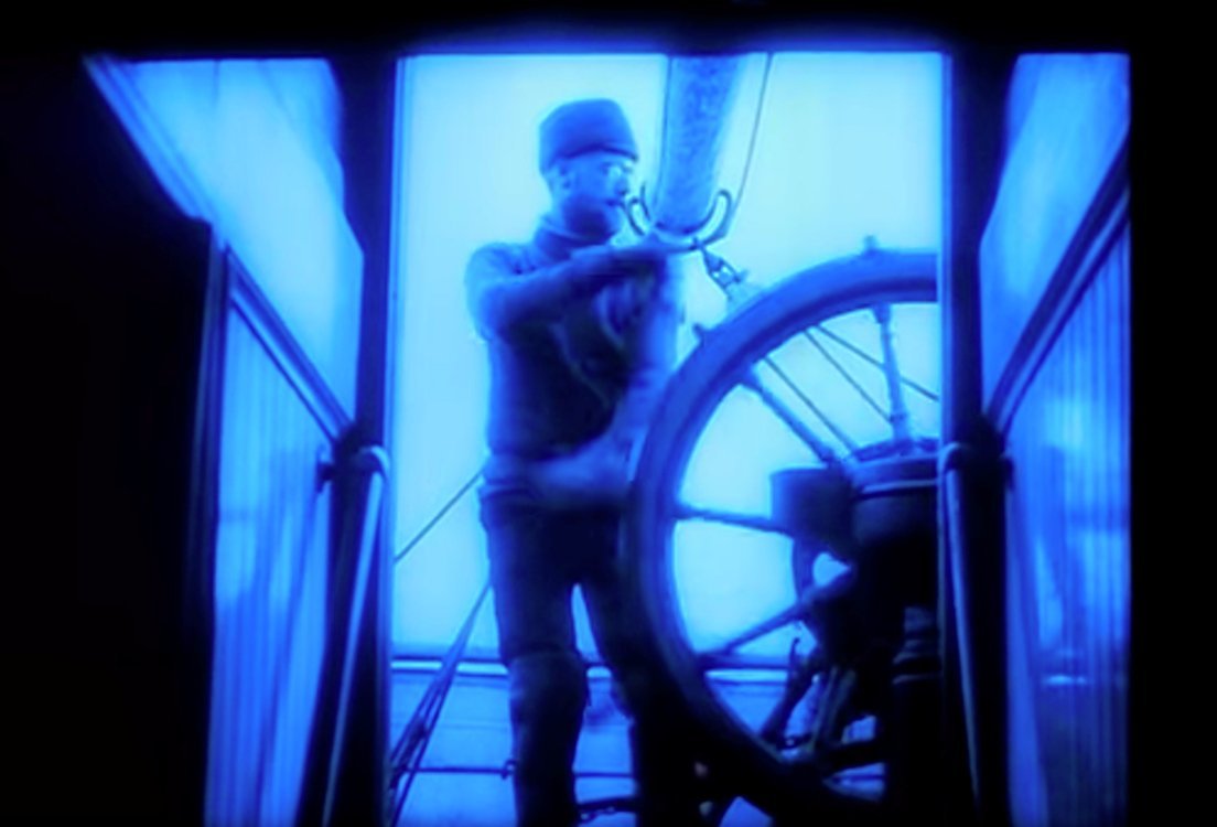
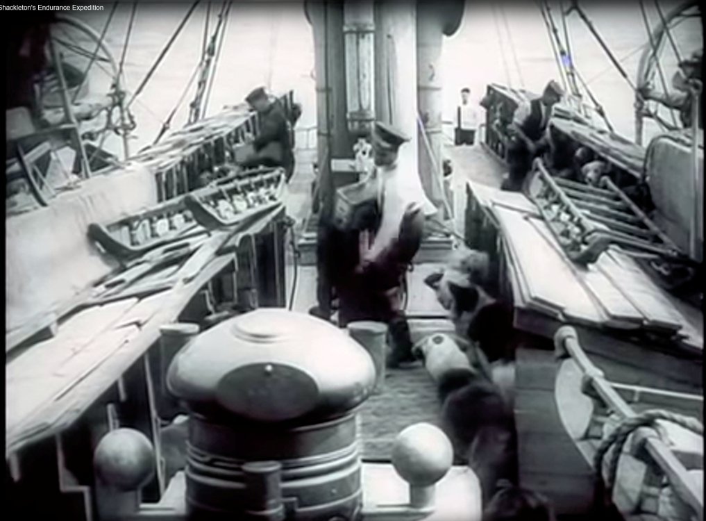
Not me, I'm building something with no photos. It's much more umm 'fun'. Meanwhile the was a program on TV the other day which had bits of Hurleys movies, I didn't know about them. Some bits from youtube. This shot caused me to speculate that they changed compasses. However I now realise that the forward compass it a normal binnacle compass and the aft one is an azimuth compass for taking sights. And alters some of my speculation as to where things were on deck as the (azimuth) compass shown is further aft.


- 205 replies
-
- 3
-
-
- Endurance
- Shackleton
- (and 2 more)
-
Owner and Master. Curious I guess. We have just been discussing water coming up around the rudder so a flush grate sounded like a silly idea, you mentioned Cheerful so I looked at her drawings. The first indeed showed a flush grate but the second showed the alteration. Most drawings don't actually show grates (another of those "we don't show everything" things) however one that does is Tower, a tender for the transport of pressed men, which shows a grating which can be locked. And by the way, your grating does look nice.
-
A raised grating to access the bread room was the norm with Cheerful being an exception, however she was later modified (ZAZ6472) so it must have been a bad idea.
-
I was thinking barrels of cognac, thus joining the smugglers. There would likely be six, they should disappear through the deck (or appear to).
-
You've said a few times "it's not Speedy", are you joining the other team?
-
I was thinking the same later but couldn't find any evidence. But I think you're right.
-
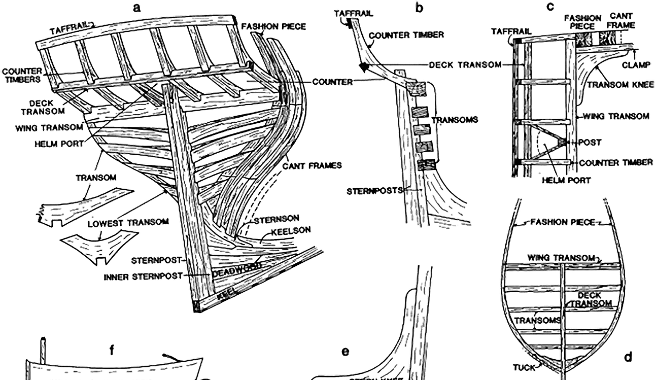
And it is your decision, you are owner and master. However, many things are left off the drawings, none of the 'family portraits' show catheads, horses, backstays, ............. as far as I can remember. Counter timbers. They usually stand on the wing transom and extend to the taffrail.
-
ZAZ6349 (Vigilant as fitted) I think is the only 'family member' drawing that shows anything. It's quite an elaborate structure with two wc's and a number of lockers and extends all the way to the stern. I suspect they had a canvas cover over the slot and tiller.
-
You might find THIS thread useful.
-
It's the Danish version, G5757 . A much nicer tiller indeed.
-
Yep. Don't blame you, lots of things just don't scale well.
-
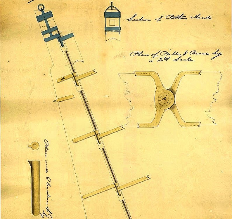
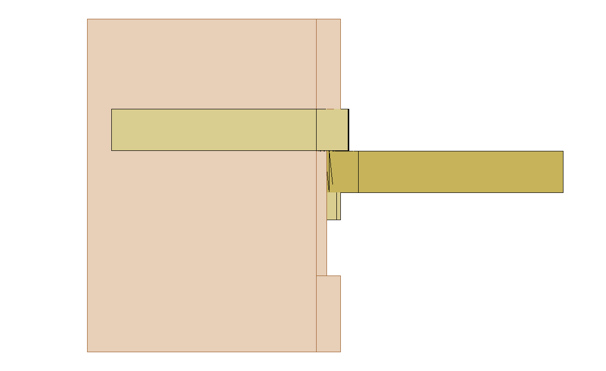
Another interesting one, dated 1830. Note that the forward edge of the pintle lines up roughly with the forward edge of the rudder and that the 'notch' is depicted dashed indicating a pocket which will look like a shallow notch from the side.
-
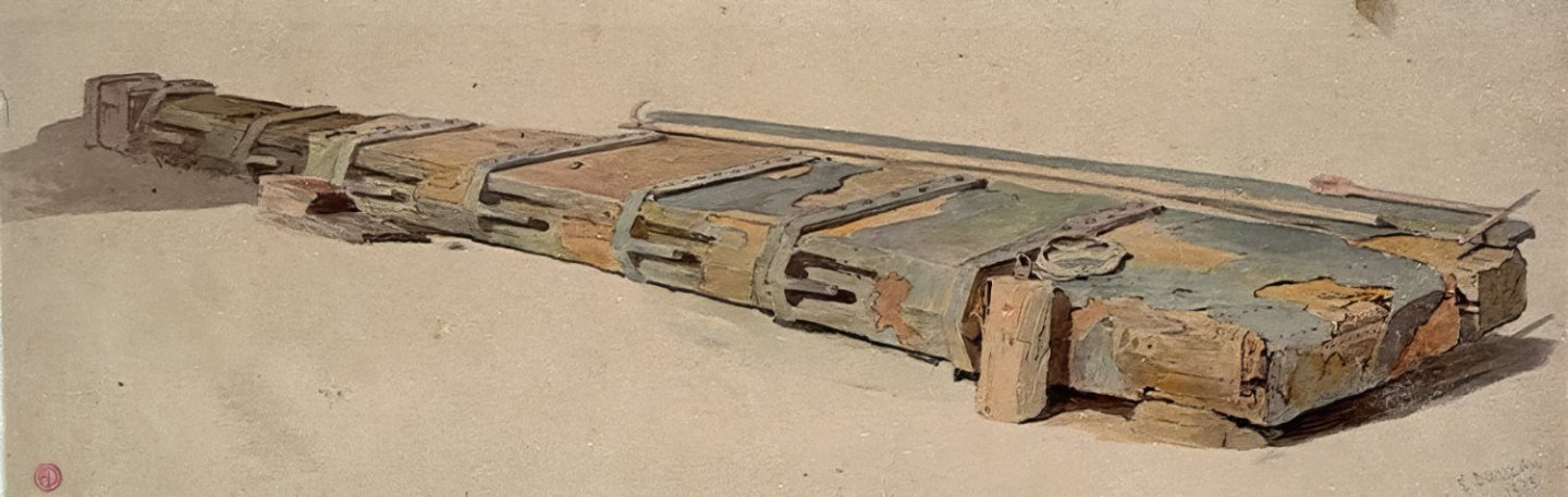
This one's interesting, Study of a rudder lying on the shore 1835.
-
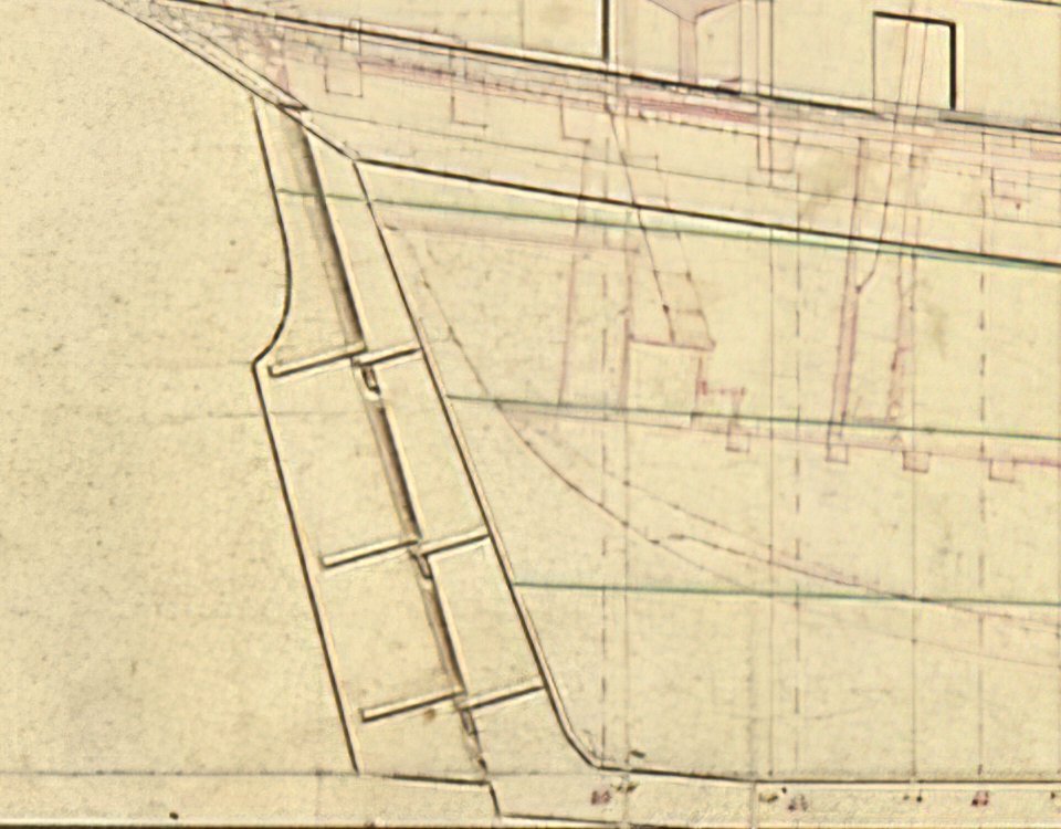
It all has to be done sometime and the brain needs a little vacation from time to time. Sometimes it needs a little ego boost (look what I did! type of thing). The sternpost probably tapered (say 8 inches to 6 inches) and also the rudder (say 6 inches to 4 inches) and the rudder had a rounded leading edge (see shading on drawing). Then again I might be wrong: https://collections.rmg.co.uk/media/543/233/l0251.jpg https://collections.rmg.co.uk/media/544/197/l0418_001.jpg https://collections.rmg.co.uk/media/543/699/l0330_002.jpg It seems the only tapering was from top to bottom. Add it to the list of things drawings don't show.
-
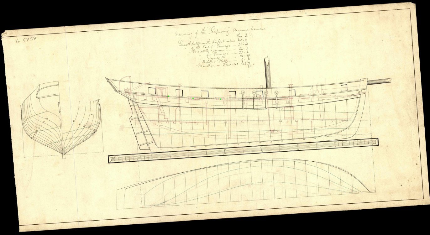
I can find only one picture showing what are probably scuppers, none of the drawings show them. However there must have been some kind of deck drainage. It is possible that the bulwark planking had a gap at deck level but Lapwing/Speedy drawings show waterways so that's ruled out, which leaves scuppers. Given the waterline, I would guess aft of the pumps possibly between the gun ports as below (tiny green dots).
-
It does. I think I'll enhance the drawing with a couple of other views and this version will be the standard one. I'll leave the complex version and may use it in a full PoF if I go there later.
-
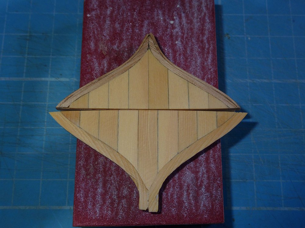
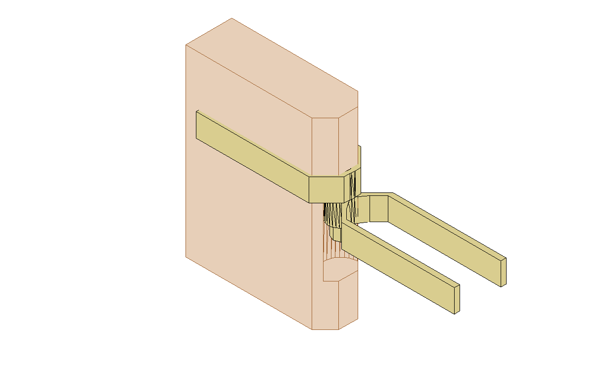
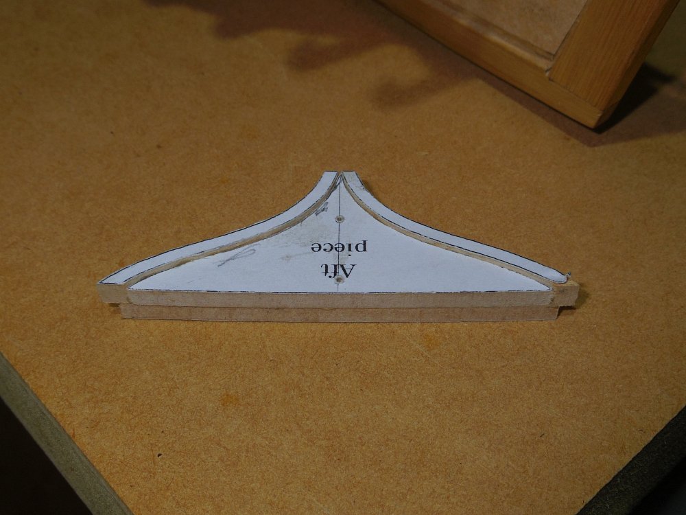
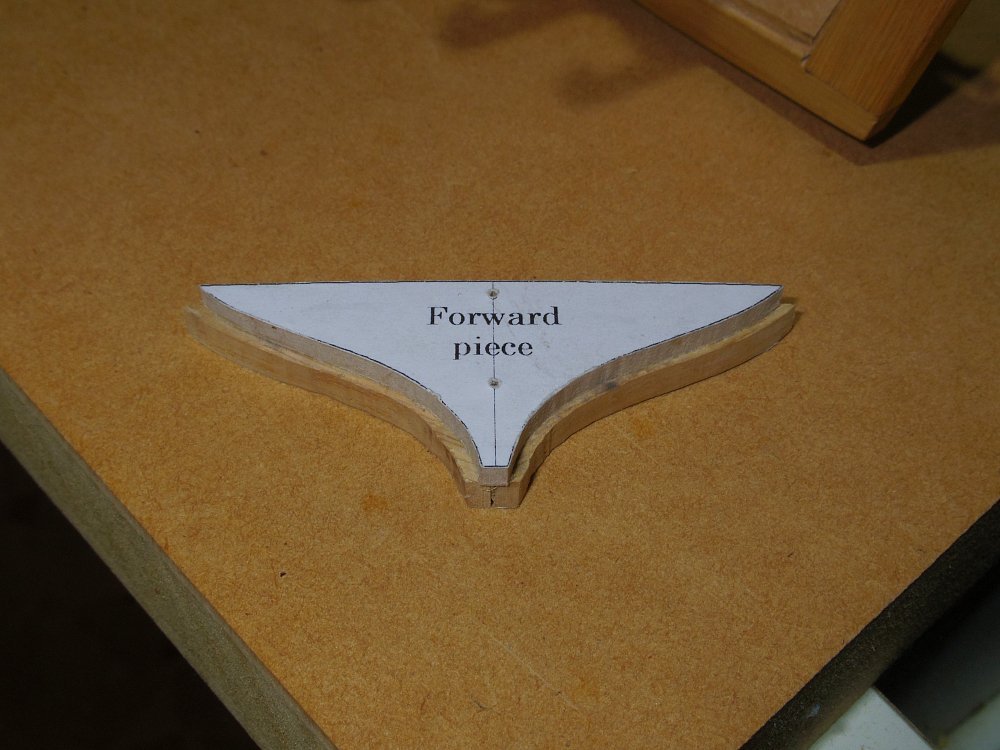
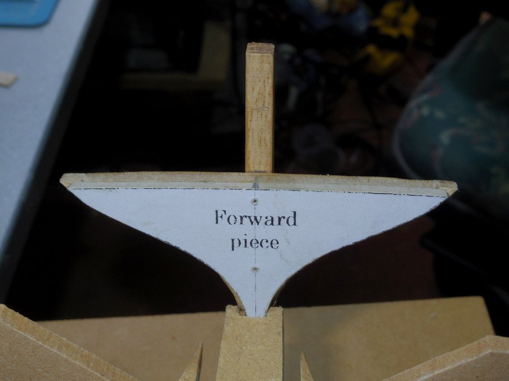
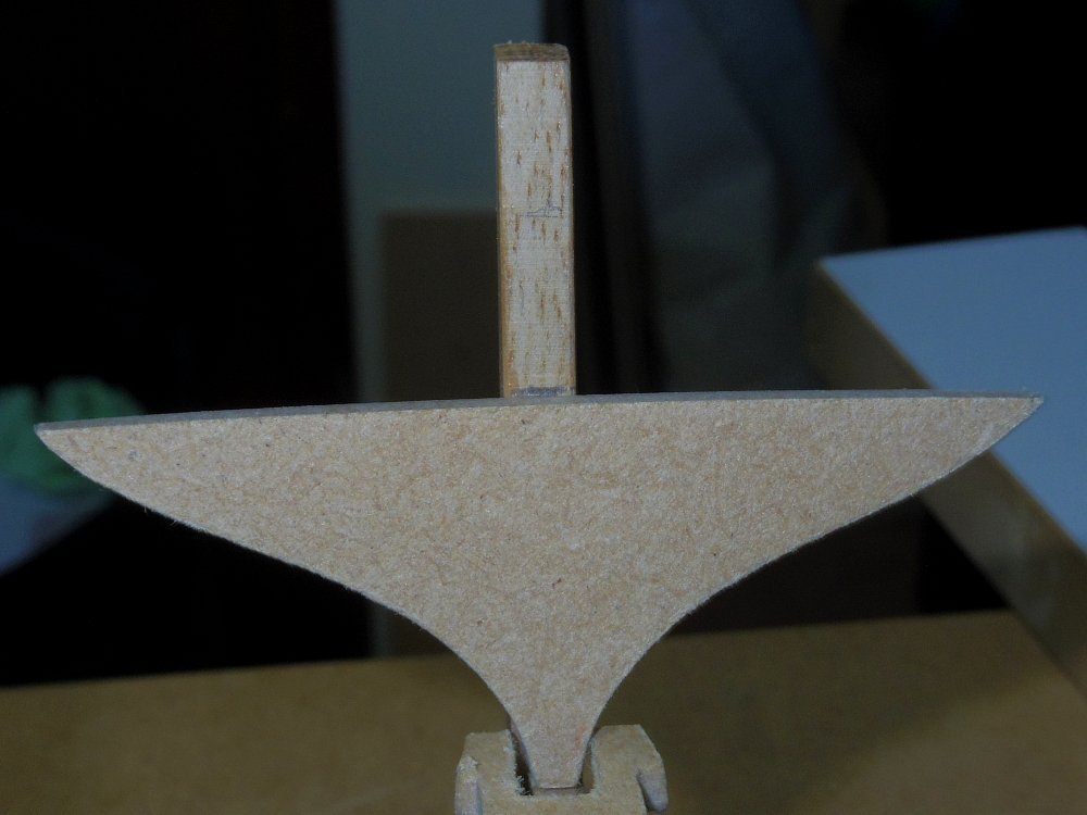
Done! Trims glued in place to the Aft piece then the Aft piece glued to the Forward piece. This provides the rabbets without having to cut them. Sitting in place. And it fits. (provided it mates up with the counter).
-
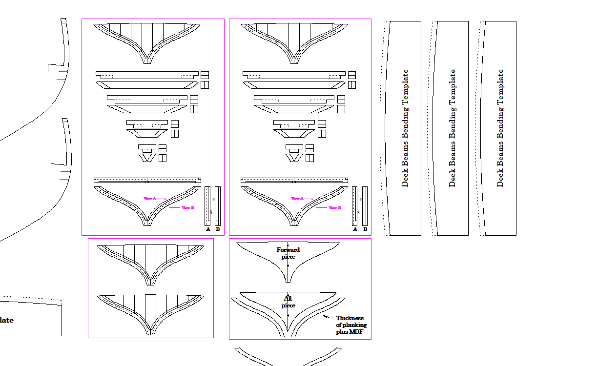
Required? Anyway, I re-drawn a simple outline an test fitted it, looks ok. I've also re-drawn the complex version and added a different simplified version.
-
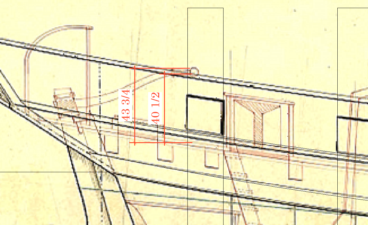
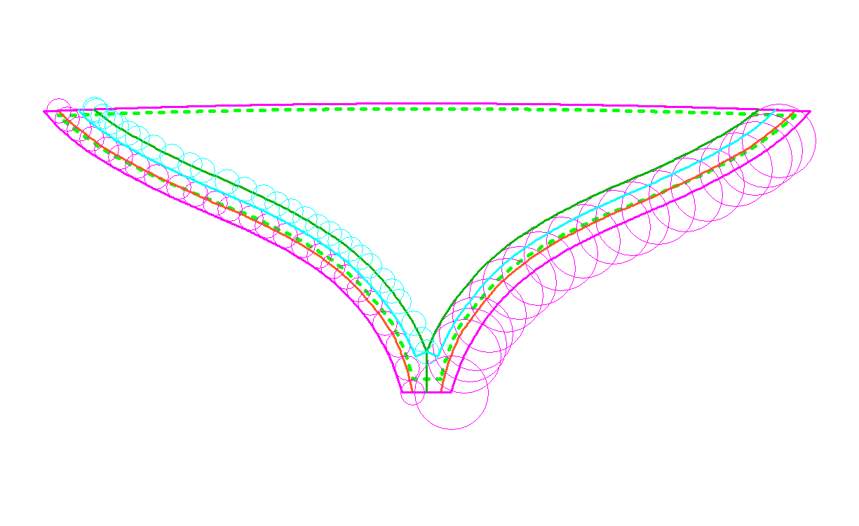
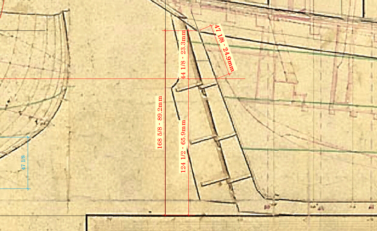
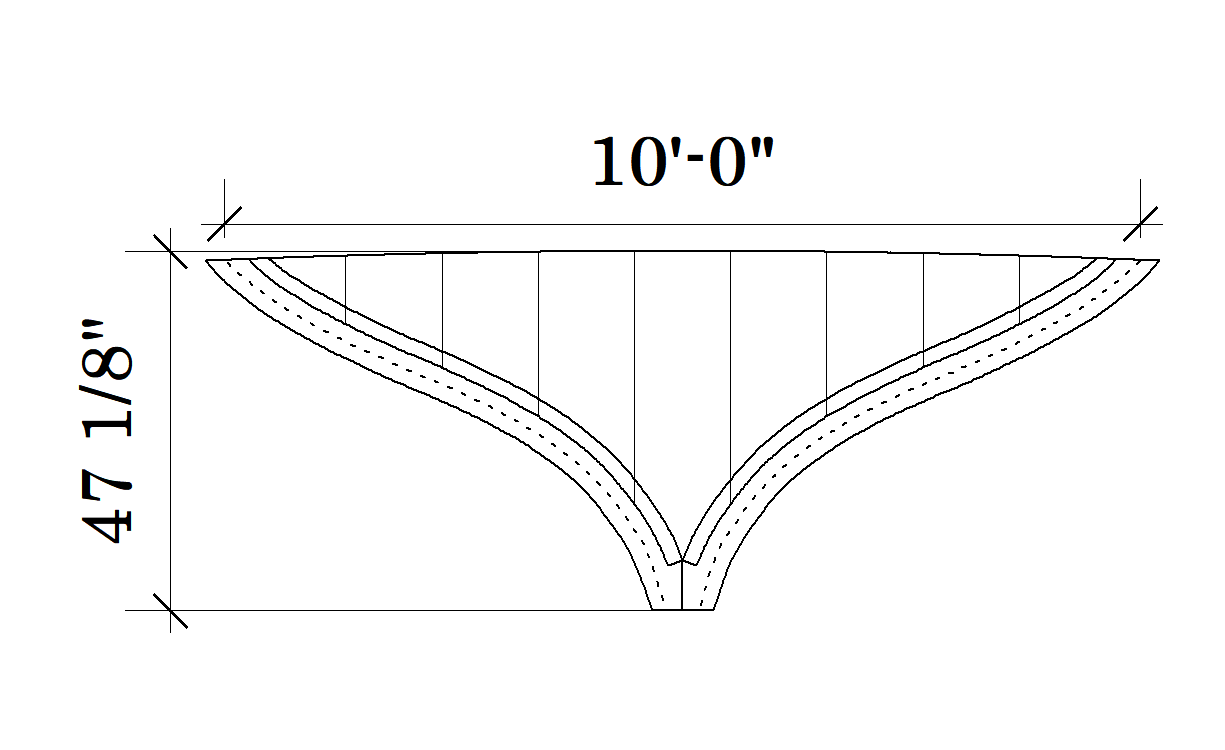
Well, hopefully third times the charm. Yep stuffed up again, the second one's too tall. So I've deleted all my transom drawings and have started agian. Measurements taken from the plans. These are in full scale inches and model scale millimetres and the two heights above keel have been transferred to the model. The other two measurements are the height of the transom, vertically as drawn and the actual height. So the drawing must be stretched vertically by the ratio 47 1/8 divided by 44 1/8 (or 24.9/23.3). The green dashed lines below represent the as drawn, the orange as stretched. Then I have to work out the trim pieces and the rabbets. As the orange line now represents the transom inside the hull planking I need a new line 2" outside the orange line. So with the aid of the small pink circles, we get the pink line (this ignores the fact that the hull widens as it goes forwards). This also gives the hull planking rabbet on the forward side of the trim pieces (between the pink and orange lines). To get the width of the trim (6 inches) I use the big circles giving the dark green line. And the small blue circles give the aft rabbet (light blue line) for the transom planking. Oh what fun.
-
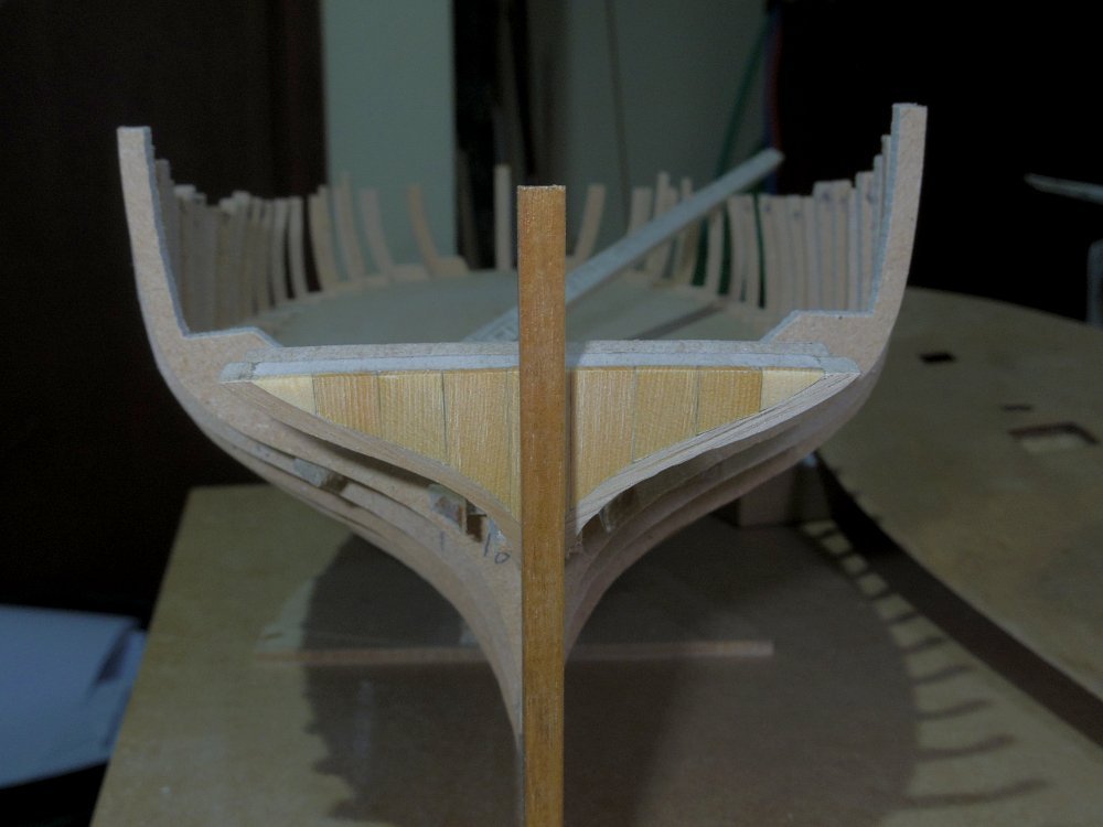
Thanks Tim. New v old. You might check out Chucks Cheerful thread ( Page 5 ), first image shows a model cutter with a similar stern and over the next few pages Chuck shows how he did it on Cheerful.