

capnharv2
-
Posts
722 -
Joined
-
Last visited
Content Type
Profiles
Forums
Gallery
Events
Posts posted by capnharv2
-
-
Steve, Geoff,
I'm getting to that point on my boats. I was going to use styrene, but Steve's comment about card stock got me thinking about doing that. Maybe do one of each?
Thanks,
Harvey
-
Very nice! We should bring our Swifts to next month's meeting and compare notes.
Oh, I tried the "view new content" on the iPod. Same response as the laptop (no new content found). My guess is it's either a problem on the site or a problem with my account. But it's a minor gripe.
Thanks,
Harvey
-
Does the line move a sail (or a spar the sail is attached to)? Then it's running rigging.
If it's called a shroud or stay, it's likely standing rigging. If it's a lift, halyard, sheet, reef line bunt line, leach line, brailing line (I know there are others) it's running rigging.
Also, standing rigging is generally black (it wasn't adjusted much and was tarred to preserve it) and running rigging is the white/cream/light brown color line.
It's fun to learn all this stuff. I'm still learning, and hope to for a long time.
If you guys want to go sailing, let me know and we can go out on our boat. Another thing to consider is take a sail on Lady Washington or Hawiian Chieftan this summer when they're in Everett (or Seattle).
http://historicalseaport.org/sail-with-us/buy-tickets/adventure-sail/
I tell my sailing students that it took 4000 years to develop the language of ships and sailing, so don't expect to learn it overnight.
Hope that helps.
Thanks,
Harvey
-
When you add the ratlines is really up to you.
Waiting till the end does give you additional space to work with the running rigging. Does any of the running rigging tie off on the shrouds (it would tie off to a cleat on the shrouds, but 1:144 scale cleats are a bit small.)?
Really, the gamut of rigging runs from yo-yos like me wanting to build up the masts and rigging the way they would have done it in the yard.
to
Building up the complete mast (with all spars, and rigging attached) off the ship and installing the mast and rig it then.
And everything in between.
The important thing is-have fun!
Thanks,
Harvey
-
-
Tony,
I'd worked on various CAD systems for 30+ years-none of this was obvious to me

I find that, as I get older, that my mind becomes more "brittle". It's harder for me to pick up on something new-like a new (to me) tool like TurboCad.
Thanks for posting that that link.
Harvey
-
Bob,
Looking good on the rebuild!
Harvey
-
Jared,
If you want cherry veneer please let me know and I'll bring it to the next meeting.
I've got a few pictures of my Swift in the gallery. I'll try to post some pictures with the cabin tops off.
Your model is looking really good! I like the shape of your cap rail at the bow and the stern quarter. Very smooth.
No, the view new content tab still doesn't work after clearing the cache and history. I'm going to try it on my iPod to see if I get the same error.
Thanks,
Harvey
-
Looks great Sarah! What metal model do you have on order?
Harvey
-
-
I only know enough about RC to cause problems, but . . .
Most of the RC sailboats I've seen are sloops with a main and a jib on a boom. I believe they are run off the same servo. The flying, non boomed jib could be more of an issue since the amount of sheet the servo would have to take in is quite large. Floyd would certainly know more about it than me.

The main topsail is easy because it's an extension of the mainsail control-same servo (unless you want to get fancy and put a gaff vang on her
 ).
).You might look at what these guys do
http://www.modelsailingships.com/
Thanks,
Harvey
-
A friend asked a couple of questions on drilling the spoke holes:
When you drilled the spoke holes, how did you stabilize/hold the work piece, V-block?
I hope this clarifies things:

How did you ensure alignment for drilling on lines perpendicular to the long axis of the work piece?
The longer lines are parallel to the long axis. As long as I kept the long lines parallel to the vice jaws I could move the piece to the opposite end to drill the hole in the other rim. I drilled one hole in each rim before I rotated the piece in the vise to do the next 2 holes. Not changing the setup between drilling those 2 holes kept that error from creeping in.
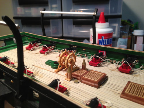
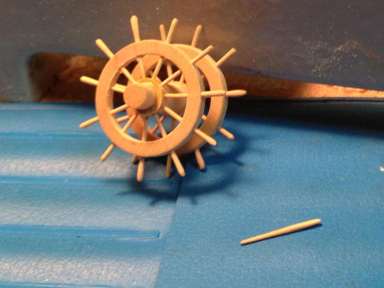
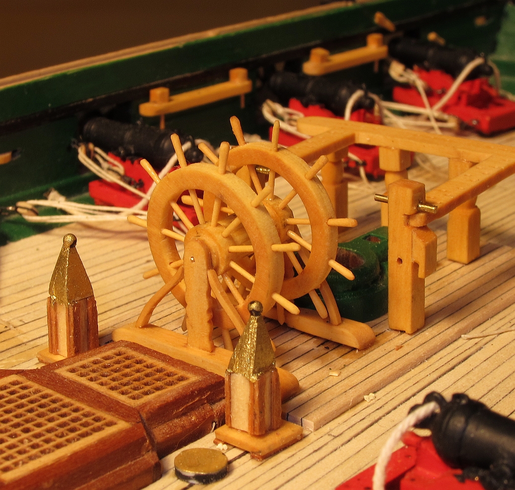
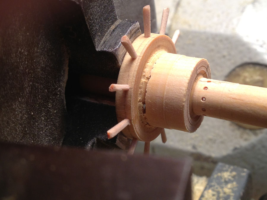
Lastly, here's a picture of the installed wheel from Saturday's PSSM meeting. Thank you Mike Graff for the excellent photo:

Thanks,
Harvey
-
Tim,
NIce! I like your method of placing the stanchion bases.
Thanks,
Harvey
-
Tony, Wayne,
I apologize for getting back to you guys so late. I appreciate your comments.
Tony, I'll look into the Paul Tracey videos. I searched for TC tutorial videos a few months ago and could only find pay sites-and I'm cheap! So thanks for the link.
Wayne, I've heard more good than bad about Turbocad(in general), and I paid for the basic application, so I want to learn it. It's plenty useful for other drafting/drawing jobs around the house (although it's still easier for me to just grab pencil and paper at this time). I tried Sketchup a few months ago, but I had a compatability problem with it on my computer, so I had to take it off. I went to the TC forums, but didn't search deep enough. I'll do that.
Thanks again for your help and encouragement.
Harvey
-
What could I do to improve it?
Well, some of the spokes that go into the hub are not in the same plane. If I had drilled it using an X-Y table, I could have reduced that error.
A dividing head would have made it easier to drill the holes circumferentially. As it is, they came out fairly well spaced.
A true boring bar setup to cut out the middle section would have given me crisper edges.
But overall, I'm pretty happy with the results:
Thanks,
Harvey
-
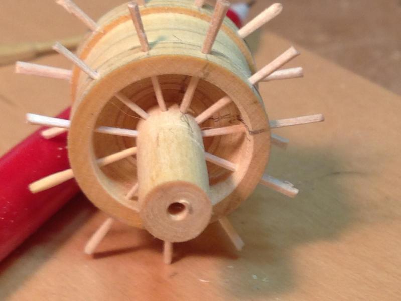
I left the toothpicks in and started to turn the middle down. That's where I learned that toothpick won't hold the rim in place after you cut it away. This picture shows the first rim cut off and removed, and the second rim just breaking loose:
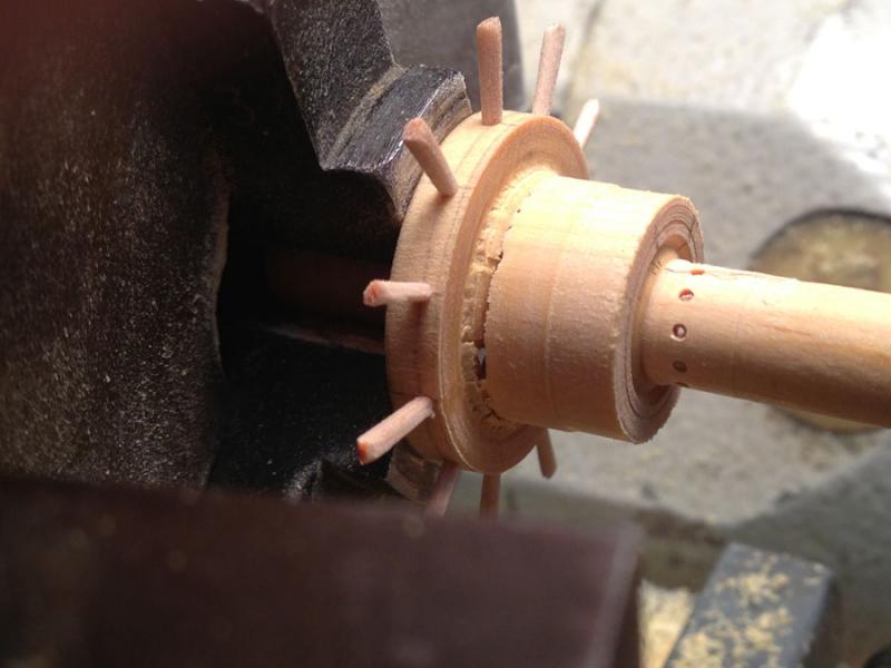
Note the pencil marks across the holes in the hub-those are my index marks to make sure I get the correct rim on the correct side and to line the rim and hub up. As much as I would like to make the rims and hubs perfectly interchangeable-well, I'm far from perfect.
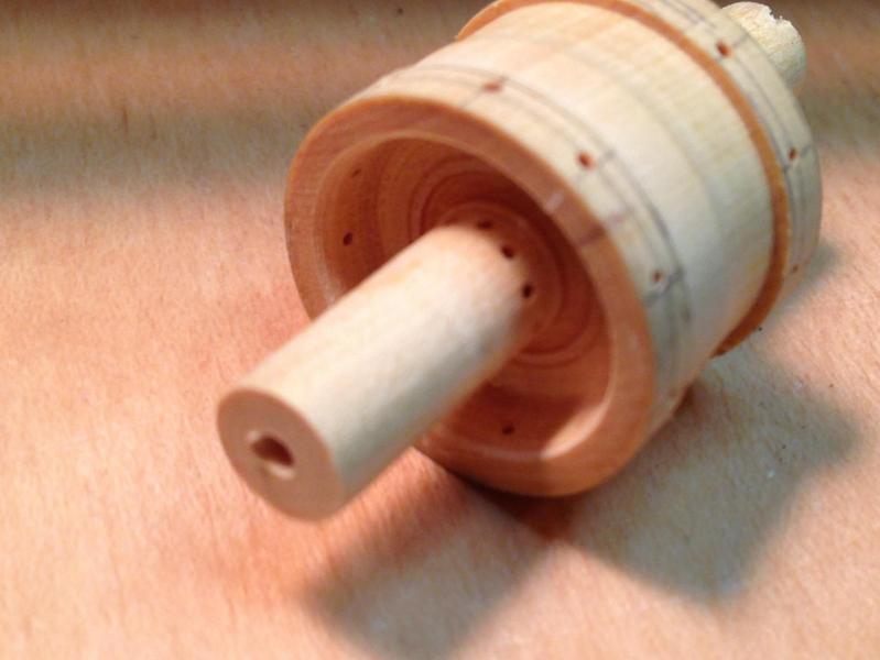
After removing the second rim, it was a simple matter to turn the center section down to the correct diameter:
I wanted something better than toothpicks for the spokes, but I'm not yet able to turn the spoke with the correct swelling and the ends and fancy features in the middle. Yet, I wanted them to fit tightly in the hub. So, I turned them down with sandpaper and the lathe
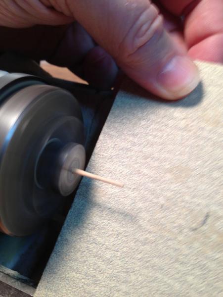
I made 16 of these and glued them into the hub:
-
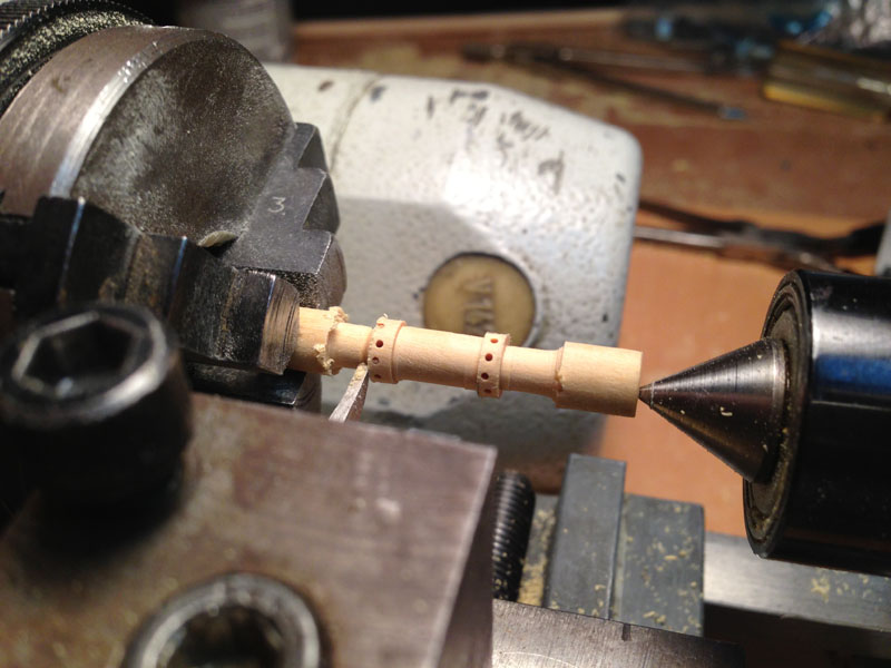
I then put the piece in a vise and drilled the rim for the spokes. I drilled only to the center (I didn't have a long enough drill bit, and the bit would probably wander off center). Then it was back on the lathe to turn the area between the rims down enough to define the rim diameter:
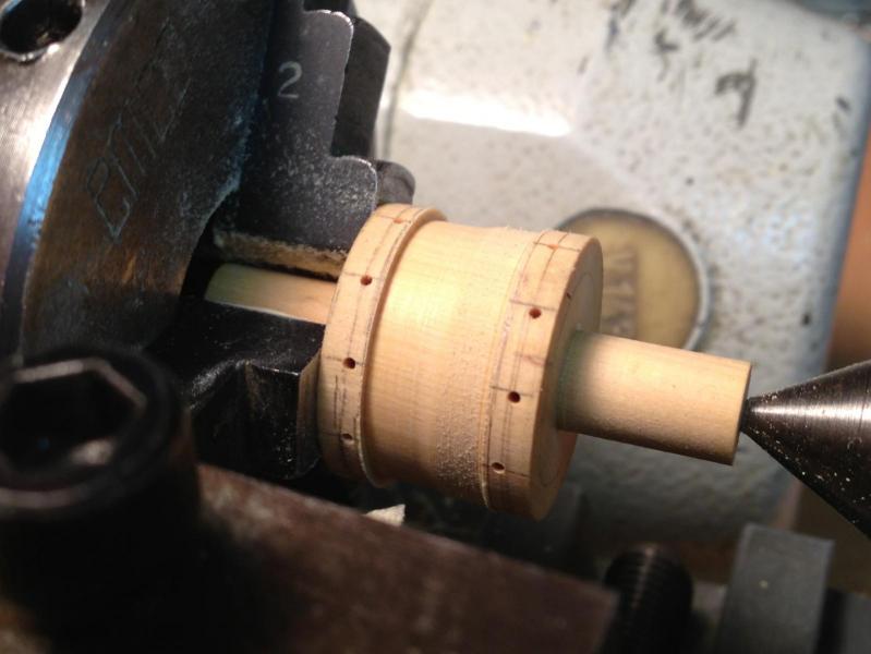
Here's where I didn't get a picture and wish I had. I made a tool for the lathe that acted like a boring bar and cut out the middle between the spoke ID and the hub OD. I made sure to cut deeper than the rim width(the material all goes away anyhow). This is what it looks like after the boring operation:
I couldn't resist-I stuck some whittled down toothpicks in to see what it would look like with the spokes:
-
I started with a 1"x1" chunk of boxwood. I chucked it in the lathe and started turning it down
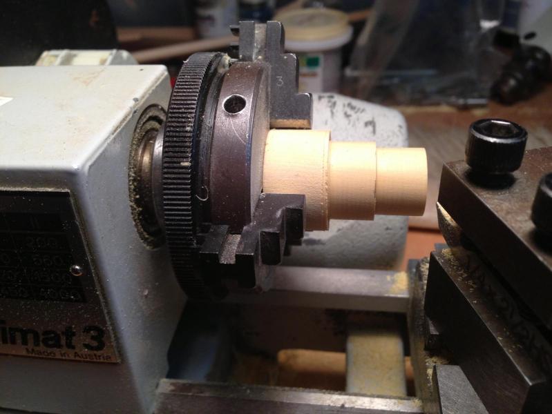
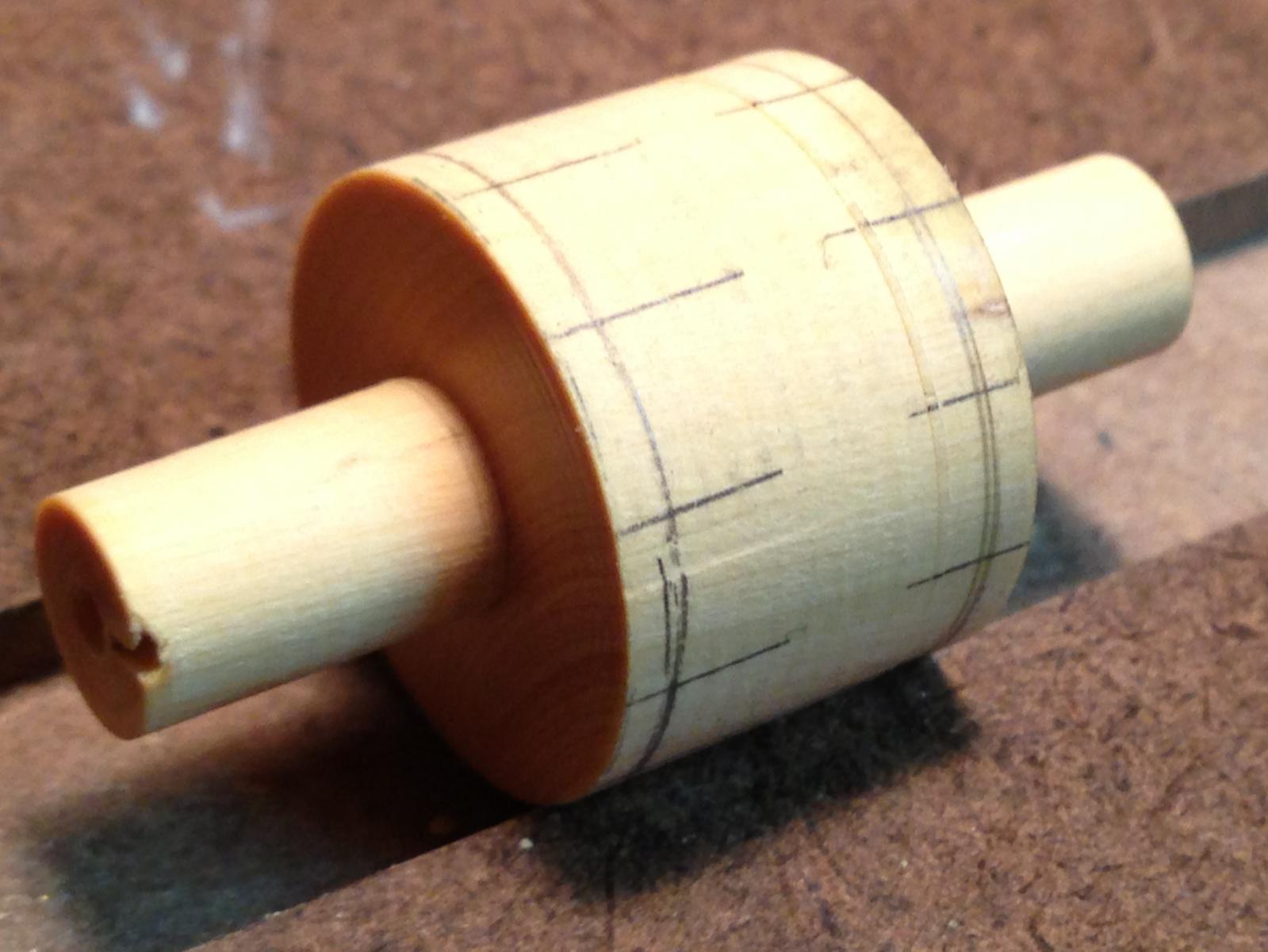
When I got to the rim outer diameter, I defined the width from outside of forward rim to outside of aft rim, and turned those ends down till I got the hub diameter. I then took it off the lathe and marked the holes in the rim for the spokes:
I don't have a dividing attachment for my lathe. And at this size, measuring and marking the locations with a protractor wasn't feasible. Further, I thought it would be an 8 spoke wheel. That makes it a little easier to get the angle (mark the rim in 4 segments and divide those segments).
Except it's a 10 spoke wheel. . .
So, I measured the circumference of the wheel on a strip of paper and divided it into 10 equal lengths. I wrapped it around the rim and marked my 10 spoke locations:

I left the hubs are long for putting back in the lathe. They'll be trimmed off later.
-
Back on MSW 1.0, I put a little thread together on how to make a double ship's wheel (on my Unimat) to replace the metal ones that came with the kit. I still have the pictures, but not the words. So, at the prodding of some of my Ship Model friends, I'll try to reconstruct the thread as best I can.
Here's the wheel that came with the kit:
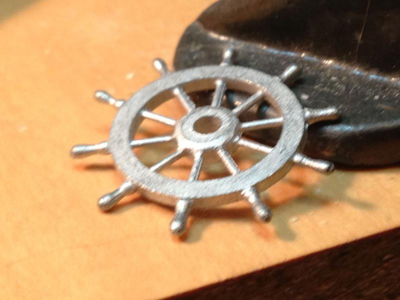
Nothing really wrong with it, but the real one is varnished mahogany. It would be hard to make that metal wheel look like varnished wood.
I read (I think it was on MSW 1.0) a way to turn a hub and spoke down, drill it, and attach spokes to make a better looking wheel. So I thought, okay, I can make 2-3-4 of these and pick the best 2 for the Constitution.
Then I started looking thru Bernard Froelich's book "The Art of Shipmodeling". My wife got it (the French version, the only one available at the time) for me for Christmas several years ago. Since then, it's always been one of my books for inspiration. Early in the book he describes a method for turning a double wheel on a lathe. It looked pretty neat, and I was itching to use my Unimat, so here's what I did.
-
Thanks Russ. Another book on my shelf that I haven't dug into-until now.
Harvey
-
Jared,
It was good to meet you and Sara today
Your Swift has come out very nicely. I hope you enjoyed it.
I assume you're done. But, if you want to tinker, and have not glued the cabin tops in place, you could detail the interior. The newer Swift has a much nicer and larger cabin area. I added a couple of bunks in the aft cabin, and a galley stove and table in the forward cabin. It was a little touch that was a lot of fun.

Thanks,
Harvey
-
Russ and Druxey,
Thank you! That was the missing piece of information. So, when the plates were put parallel to the waterline in the 19th century, did the batten go away? Or was it a gradual transition?
What references would have some of this information?
Thanks again,
Harvey
-
-
I haven't plated very many ship models (1 so far), but I've looked thru several books on the subject, and now I have some questions.
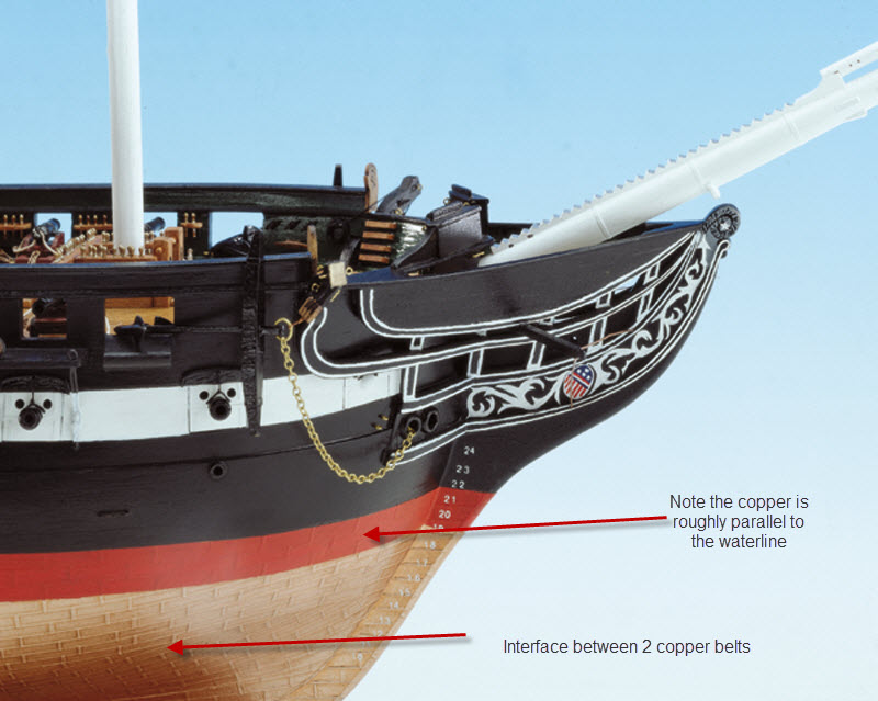
Most of the older ship model books I've looked at (Ship Modeler's Shop Notes Vol 1, Longridge Anatomy of Nelson's Ships, etc) show planking in several bands. The lowest band starts parallel to the keel, and when the bow and stern plates get closer to the waterline than amidship plates, another belt is started, to straighten the curved copper line out, until it too, has bow and stern copper rising faster than the midship plates. I've read that there are usually 3-4 belts of copper, the last belt about 6-7 plates wide, and it's pretty much parallel to the waterline.
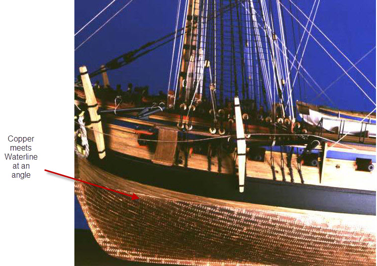
Lately, I've noticed that some models are being coppered without these belts. When looking at the copper from the side, they seem to create a set of "smiley faces"(I couldn't think how else to describe them), with most of the plates trimmed off at the waterline at a 15-20 deg angle. I've looked thru some of my newer reference books and see they reflect this different(to me) coppering pattern.
Is there new information that copper plating patterns changed as the copper plating process developed? I'm curious. Of course, the builder coppers the hull based on what he or she wants to do. But I would like to know if something new has been discovered.
I'll try to find some pictures to show the differences (as I see them). Otherwise, opinions and comments are welcome.
Thanks,
Harvey


USS Constitution by Modeler12 - FINISHED - Model Shipways
in - Kit build logs for subjects built from 1751 - 1800
Posted
Jay,
Looks really good.
You make the point that rigging is fun, and you sure make it look fun. I was going to put my Connie aside after I was done with the topgallant rails and ships boats, and spend some time on the deck and chainplates on my Flying Cloud. Maybe I'll start into rigging the Connie instead.
hmmm.
Thanks!
Harvey