


oneslim
-
Posts
202 -
Joined
-
Last visited
Content Type
Profiles
Forums
Gallery
Events
Everything posted by oneslim
-
 Part 5 Here the front view of the center pod with the cockpit installed. The rear view. From the left. And from the right. These are the turbo-superchargers, painted with Alclad II Lacquer Steel and Jet Exhaust. Mixed at three to one. The same parts with a weathering of AK Acrylic Rust Effect colors. I know it looks rough, but after drying for a day, some work with a stiff brush they will look much better. Here they are being test fit. Bare Metal Foil has been added to the leading edges of the wings. The area covered were the inter coolers for the turbo super-chargers. The internal structure was corrugated with the liquid coolant flowing through. All the early P-38's had this system. It caused many maintenance problems with constant leaks and was easily damaged. This system was converted to fuel storage starting with the 'J' model. The inter-coolers were moved to the bottom of the engine nacelles between the oil coolers giving the deep chin look. I think they spoiled the profile of a very sleek airplane. More to Come, BobW
.jpg.8aac9c0766a242353e68afd316dbeb95.jpg)
.jpg.3a8de2a88331dab032f1705ae7c9de33.jpg)
.jpg.ecdf565d2751ecc503634cbd2f8ee02c.jpg)
.jpg.7d970dedc6e079a2c739ac47a4815552.jpg)
.jpg.1f54c4bed154f287000870be9f7d0792.jpg)
.jpg.0c4ffef844d6aa979d94615d5bbe21af.jpg)
.jpg.6a4772d7e87ba9d5d22640843a312926.jpg)
- 83 replies
-
- 11
-

-
Roger, I think it was up. Also he took His Wife up for a spin. BobW
-
Popeye, Looking good!!! BobW
-
Popeye, I make them as I go along. They are held together with double stick 3M tape. They can be used over and over, changing them to fit. Some are scrape boxwood, and also 1/4" plywood from a hobby shop. Charles, I read the The Lost Squadron years ago. The newish book Aces High by Bill Yenne (ISBN 978-0-425-23230-9), is a bio of both Dick Bong and Tommy McGuire. It covers their war history and their race to be the top scorer. Gen, Kenny let Bong freelance for the the last year, while McGuire was tied down as CO of 431st FS. McGuire was also grounded while Bong was on His way back to the US. Roger, The Duluth Aerial Bridge story is in the same book. BobW
-
Thank You for the Nice comments Gentlemen. BobW
-
Part 4 Thanks for the 'LIKES', and the great comments. This is the bottom of the nose section with the 1/2" chrome steel ball as nose weight. Held in place with white glue so it dose not rattle around. Shown is the main spar that sets the dihedral. It has the nose gear bay attached. Notice the bulge that protrudes into the cockpit floor, This is for the nose wheel when retracted. Here Here is the belly pan with the spar and nose gear bay attached. The ball weight also is seen. This is a test fit of the top and bottom of the fuse. The silver on the inner wing is Bare Metal Foil. This was a high wear area because the pilot and maintance people would climb up to this area to enter the cockpit or do work via the self storing ladder to the rear. This is the cockpit tub. The wires are for the radios on the shelf behind the pilot. Here is the radio rack. The fine wire is the radio antena leadin, which passes through the rear canopy. And here is the pilot seat. The back cushon was made from paper and thin plastic stock. The decal was home made and states 'US AIR CORPS". More to Come BobW
.jpg.18dc4aceb5c10fe52a4f3acea044691f.jpg)
.JPG.bc78832262cc24b890e93f49690a12a5.JPG)
.jpg.e38db79255070a682fc368e0069de73a.jpg)
.JPG.b28be8981b194a6efd501fc80fa25b85.JPG)
.jpg.84f921df1603ecc205348fd08c5bf6ef.jpg)
.jpg.5f40e6aeb092a174e968eb8dd5440ce3.jpg)
.jpg.780af0daa0a3066d14ef94663ec0b96c.jpg)
- 83 replies
-
- 12
-
-
Roger, It sure is, I must have looked at 10,000 drawings of the P-38. Thanks for the 'LIKES". More to come BobW
-
Thanks for the comments and 'LIKES". Mark, I found it on a drawing from this site: https://aircorpslibrary.com/ The first month is free. I joined and was able to print quite a few drawings for only 5 bucks a month. They have all the major fighters and bombers of WWII. One can quit at any time. Never have seen a site like it. BobW
-
Part 3 This is the floor and bulkheads. The black tube snaking over the oval hole is a pilot's relief tube. It would be just under the seat with in easy reach. The exit was a small metal tube under the fuse. The green curled tube is the pilot's oxygen supply. Port side of the cockpit tub. The engines control stand has two levers for the Throttle, Richness, Props angle, and Props feathering. This is the starboard side showing Radio Tuners and their wiring. The lever at the top under the wire to the control column is the flap control. A note about colors. Lockheed had a large contract for hundreds of Hudson bombers for the RAF. The RAF had strict paint specs which Lockheed had to adhere to. So Lockheed set up a deal to get large amounts of RAF specked paint made in the US. Lockheed requested permission of the US Air Corps to use paint on hand for P-38s. They agreed. So in the cockpit RAF Cockpit Gray Green was used. The upper surfaces were RAF Dark Green, and the lower surfaces were RAF Medium Sea Gray. This continued until the silver J models. This explains why early P-38s look different in black and white, and color photos from other US planes. More to come, BobW
.jpg.3b8a5f6286c933ab32f7730a41aca3dd.jpg)
.jpg.11cb1329152e6009689ff67a301eea27.jpg)
.jpg.6eb386746fe8acba05fcfeecf16555f4.jpg)
- 83 replies
-
- 12
-
-
Canute, Yes, the kit comes with three chrome steel 1/2" balls. One for the nose and two for the engines. I'll show how they are 'trapped' when I get there. BobW
-
Really Nice Paint Job. BobW
-
Part 2 I am using a 'Eduard Brassin" P-38 G Resin and Photo etch Cockpit set. This is the floor with a forward bulkhead and aft one. The oval opening in the floor is for the front wheel when it is retracted. The cockpit is a tub with no frame work protruding in. Wheel bay is it's own tub. This is the port sidewall. The round object near the center is the cover for the hand crank mechanism to roll the side canopy up & down just like a car. Side canopy windows were always closed during flight because if down would cause tail buffeting. The large area to the right is the engines control stand. This is the port sidewall. It has three radio tuners at top center. The boxes below the tuners are switches and radio filters. A sideview of the pilot seat. This is a view of a restored F model. This shot is of an late H model with the side canopy rolled down. It also has an updated radio system. The rear canopy glass was removed to service the radios. Notice also the thick armored glass with the head pad and bracket at the bottom. More to Come BobW
.JPG.04784074927fd41f39d0c0f46c42e7df.JPG)
.JPG.11cc2fb1f7d72356a0ccbe14d8102923.JPG)
.JPG.3ad6d34c512d51af28e981a0dfa234d2.JPG)
.JPG.beaa7bdb8274f6489322b6cef1ed5e6b.JPG)
.jpg.6ec5a1aa1bcded2345630b4fd7b49009.jpg)
- 83 replies
-
- 10
-
-
Thanks for the "Likes" Canute, I've seen the mounted PUDGY V ( L model ) many times, only about an hour's drive from home. My Dad and I would go to the annual air show. McGuire Died in a borrowed P-38 L, He was fearful that a silver PUDGY V would scare off any targets. The guess is it was scraped in theater. BobW
-
Part 1 This is a build of Tamiya's new P-38H-5. The kit is the second P-38 released this year. First was the P-38F/G back at the beginning of the year. I have one of those that I was going to modify into a G model. When this kit was announced in March I put in a pre-order. It didn't show up until the middle of August. I have wanted a early model of the Lighting for a very long time, Just love the sleek lines. When Lockheed moved the Inter-Coolers from the leading edges of the wings to the lower nacelle in the J and L models it spoiled the smooth lines of the air frame. The subject will be Tommy McGuire's PUDGY II, His second P-38 of five He flew in the 475th FG 431st FS. McGuire was the second highest Ace of WWII with 38 Kills. The Kit Sprues: A Sprue B Sprue C Sprue Dx2 Sprue F Sprue G Sprue J Instruction booklet Color decal placement Decal placement 2 Instructions Kit Decals Aftermarket Decals Color Profile More to Come, BobW
.JPG.5410e43330c2261efea9536d4c9ee4d6.JPG)
.JPG.f08b18900b69ea67b4b54298bdf94234.JPG)
.JPG.be9a549425fa1868eafb40770a32bb0e.JPG)
.JPG.2d84ac48bd5bd2c83e00d9138958aae1.JPG)
.JPG.6e848c1e9c94069481db26dbd27b74f8.JPG)
.JPG.f17db852a50c3efcc37f2fd7104a2614.JPG)
.JPG.d853ce23b46c45a8f1549221a23511ee.JPG)
.JPG.4b6727a63c730a95feeba6a0bba7ed64.JPG)
.thumb.JPG.ba717dc6bbab410856ed54da781b8ae1.JPG)
.JPG.265d9e8bc996d6153224fbeb4d117fa8.JPG)
.JPG.d3c3abddff20589dbc8b83961579a1c9.JPG)
.JPG.dee252f06f77856af43002af9a6fb06d.JPG)
.JPG.0ddccb03537f400cb64d228f88bf1d06.JPG)
.thumb.JPG.224bc44f31eea175371b7fd6e20819b0.JPG)
(Medium).jpg.6c1da0657ecc67b13d9f95c29f48f864.jpg)
- 83 replies
-
- 14
-
-
Thanks everyone for the comments. Matthias, The figure is a casting of a RR Engineer in 1/20.3 ( 15mm) scale. Just there for looks. BobW
- 87 replies
-
- 2
-
-
- medway longboat
- Syren Ship Model Company
- (and 1 more)
-
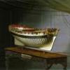
Finished It's been some time since the last update. I have had a very busy summer with storms and then doctor visits. Below are the final photos showing the oars, boat hook and the base. Thanks for Looking in, BobW
.jpg.a8328c17dd8909ef2017e7af791cc6cc.jpg)
.jpg.c2f55f20d1bf006b07daaa6a52d2365c.jpg)
.jpg.d87b163c20b18d7f0c9342fdc600ba65.jpg)
.jpg.9ef02b134fbad6f6cefc1dac8bcb910b.jpg)
.jpg.c5a4a3c34bc2635ef6ce8f6bc87e887a.jpg)
.jpg.9d03e53c2b92f47b279e4a0ba1b3f0cb.jpg)
.jpg.f77c8ce743184eb094f60878e4f4dc4a.jpg)
.JPG.8fead3bc11c837fec242bfa7a47d23f1.JPG)
.JPG.8e1a22a8ae22c680ac7a847d7b250152.JPG)
- 87 replies
-
- 17
-
-
- medway longboat
- Syren Ship Model Company
- (and 1 more)
-
When I was kid in the 50's, my dad who was a Naval WWII and Korea Vet, acquired some anti-slip stick-on strips. He used them on the cellar steps which were painted 2x10's. They were a black color with what looked like glass beads imbeded. At the right angle the had a sparkle effect. These strips lasted 40 years that I know of. He was one that always went to surplus sales at the Philly Navy Yard, came home with all kinds of what my mom thought was junk. BobW
-
Very neat, beautiful job Bob. Congratulations on a fine model. BobW
- 170 replies
-
- 1
-
-
- medway longboat
- Syren Ship Model Company
- (and 1 more)
-
Part 17 I've pretty much finished with the rigging. Here are a few shots of my progress. Next up, the base board. The flag. I decided to make a 'Admiral of the White' Flag just to have a different look. I made it a little long on the heel side to wrap around the toggle line I made. This starboard side is not a good view, but the toggle can be seen on the vacant halyard. This shot shows the toggles. Shrouds, Deadeyes, and Lanyards. Stern view. The figure is from a 1:20.3 scale railroad maker, I know he is a little oversized. Looks good anyway. His head seems to be looking where it should. More to Come BobW
.JPG.1097d559de0dac9e30da5a88b0670c0e.JPG)
.JPG.802dfc40f4d2a530983637daf8579254.JPG)
.JPG.eb3f8cdf937b5c9195dc2bebfbf08832.JPG)
.JPG.417b38f0083ef6a0ab57710cb03bb7ff.JPG)
.JPG.ca43c4e7dd41b6035951b1918dee0a87.JPG)
.JPG.eb12b0022004d743eb87cb83095ac2a9.JPG)
.JPG.bca31d3df984e25ab0bea9572c09a2de.JPG)
.JPG.60b569fb2e24068176073e35f6b7eaa8.JPG)
- 87 replies
-
- 13
-
-
- medway longboat
- Syren Ship Model Company
- (and 1 more)
-
Bob, That's a great job on the oars. BobW
- 170 replies
-
- 1
-
-
- medway longboat
- Syren Ship Model Company
- (and 1 more)
-
Eric, thanks for Your thoughts. BobG, my daughter dose not have Covid-19. She had heart damage from radiation treatment for Hodgkin's when she was 16. Had to have a aortic valve replaced with a metal one in September. She spent 60 days in U of Penn because of complications. Then she had a stomach bleed which meant another week in hospital. It's been a long haul. BobW
- 87 replies
-
- 2
-
-
- medway longboat
- Syren Ship Model Company
- (and 1 more)
-
Thanks everyone for the 'Likes'. Greg, My daughter is much improved, I speak with Her quite often. She is toughing this covid-19 alone in Her Townhouse. The youngest son is with His father, because He's afraid of transmittance, since he was up at Rutgers. He was just starting spring break when the lock down hit. And the oldest is in Pa. working for Comcast from home. BobG, My guess is they slacked off the sheet to move it around the Tiller when tacking. I don't think this was a one man sailor. Too much to handle alone. Thanks BobW
- 87 replies
-
- 2
-
-
- medway longboat
- Syren Ship Model Company
- (and 1 more)
-
Part 16 Well the Head Sails, Foresail and Jib, have been rigged. This image is from Eighteenth-Century Rigs & Rigging, Karl Heinz Marquardt. It shows an rigged Longboat with the sails set. Shown are a number of Items such as: 1. The Boom Sheet Tackle is before the Tiller. 2. A Single Purchase Tackle Halyard at the throat of the Gaff Boom. 3. The run of the Sheets for the Head Sails. 4. A Halyard for the Main Sail to haul it to the boom end. 5. A single Shroud. This image is from The Arming & Fitting of English Ships of War, Brian Lavery . It shows a Mid-18th Century Longboat. Items shown are: 1. The Boom Sheet under the Tiller. 2. The topping Lift has a Single Purchase Tackle. 3. A Single Purchase Tackle Halyard at the throat of the Gaff Boom. 4. The Backstays are close to the Shrouds. This is an overall view of the starboard side. A starboard fore quarter view. A port fore quarter view. A port aft quarter view showing that the Backstays have been shifted forward by one thwart. The Mast Head, getting very busy. Much of this rigging has been changed. If One looks closely the hooks are moussed. I have added two belaying pins. One forward for the Jib Outhaul. Another just in front of the mast for the Gaff Boom Halyard. There is much to do inside. Including Coils, Grapple, Shrouds, and Oars. More to Come BobW
.jpg.9dc6f4e5b0812f94337dd5a178d448e9.jpg)
.jpg.ee50da8d7ef469f27c17d371ee391138.jpg)
.JPG.4b2ddc5236089946feabf355307f8ad3.JPG)
.JPG.8178577f777b1cffdb0779e65ba9f83b.JPG)
.JPG.2c3598675d2883d7a066de193f2bda37.JPG)
.JPG.5673b771daff70194ce3dbc4e3db7c7b.JPG)
.JPG.d9c9ff65ad2f705b8b7bf6520f527550.JPG)
.JPG.6804c68e0f56a197ea445fb87d53afba.JPG)
- 87 replies
-
- 16
-
-
- medway longboat
- Syren Ship Model Company
- (and 1 more)
-
Thanks all for the 'Likes'. BobG I appreciate the comment. BobW
- 87 replies
-
- 1
-
-
- medway longboat
- Syren Ship Model Company
- (and 1 more)
-
Bob, That sure is a sweet build. Are You going to use Chuck's base? BobW
- 170 replies
-
- 1
-
-
- medway longboat
- Syren Ship Model Company
- (and 1 more)
.JPG.fe3de05ccc054906e50cb78846a2373d.JPG)
.JPG.51389a0c07901a43240902168fe3daf1.JPG)