

KrisWood
-
Posts
314 -
Joined
-
Last visited
Content Type
Profiles
Forums
Gallery
Events
Posts posted by KrisWood
-
-
-
-
Hi everyone! It's decision time.
I am unable to proceed with a wood project at the moment. In the meanwhile I'm going to proceed with card unless anyone has a CNC mill and wants to collaborate on making parts. (Anyone here interested?)
Now I'm considering two questions:
-
What is a good scale for working with card? 1:75 fits the entire keel on a single US Letter sized sheet of card stock so I can print it in one piece, but I think the parts will be too tiny to get the level of detail I'd wanted for my project.I've decided to go with 1:50 - Since this thread is for my wood project, should I start a separate one for my card project, or just keep posting here? I've also got a separate thread for my CAD related questions in the CAD forum.
-
-
Ha. Hahaha. HAHAHAHAHAHAHAHAHAHAHA.... 🤪
I went and added my beautiful, new, mathematically derived lines for the stem back into my guesstimate that I'd made before the new, more detailed plans and numbers were published. All that work and none of the lines moved by more than a centimeter... My old guesstimate was as close as makes no difference at scale... 😆
That said, I guess I'm going back to a previous save and simply converting my files to a card-friendly scale/format...
Edit: Also, the way I ended up getting a three dimensional stem-top was to take Johannessen's cross sections and adapt them to Bischoff's numbers, then voila, it matched Saga Oseberg. In doing so, I realized a simple truth about all Oseberg reconstructions. Every last one of them is historically inaccurate.
In Mr Finderup's "Saga Oseberg" book, he explains that they ran out of time at the end of the project to fully analyze the remaining fragments of the stem top, so they went with a mathematically derived approximation in a single solid piece, even though the original used multiple pieces.
Comparing excavation drawings to both Johannessen's and Bischoff's reconstructions, the original stem top would have been somewhat larger and at a different (somewhat unknowable) angle. Because it makes zero difference to the functioning of the ship, I think Ms Bischoff's approach is the correct one. Johannessen did what looked good for the museum display. Bischoff did what functions given the most probable dimensions of the planks which made up the hull of the ship.
-
-
8 hours ago, Waldemar said:
The size of the inserted bitmaps into the posts is reduced (probably to a maximum of 1440 pixels of the longer side).
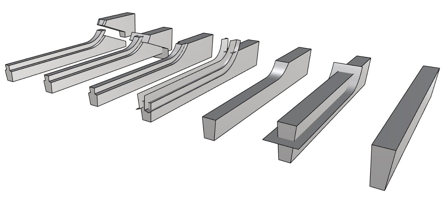
Yes, these are quite nasty shapes to model, but possible. Try it this way, but your initial polysurface needs to be closed (for better clarity and less working time a straight element in this sample):
This is not the only way, but probably the most convenient.
Count me amazed. How do you do that so fast? Are you using Rhino?
The rabbets can be modeled more simply as being perpendicular to the inside of the stem and not cut out. That's how they were made on Saga Oseberg. They didn't cut them until they were ready to lay the next plank down, and then they cut it to the depth of that plank.
-
Hmm when saving it as a jpg it blurred the numbers horribly

-
-
-
The curved stems of Saga Oseberg pull the bow up slightly. The straighter, narrower stems of Dronningen caused it to dive naturally at the bow. 😣
Part of the problem with Dronningen was that it was built from Lundin's 1957 plans. Lundin didn't have access to measurements of all parts so he had to guess more.
-
I think she got it closer than the museum reconstruction. The original conservator didn't take into account that the keel had been flattened by the burial mound settling on top of it for a thousand years. He also assumed the decks/oar holes were flat, when they actually line up better if curved. The knees were broken in multiple places so any reconstruction is somewhat guesswork, though the museum display has them shorter than the excavation drawings.
(Note, the original conservator also didn't have computers to do wood grain analysis to figure out which way the curves of broken pieces went together)
Anyway, like the two of you suggested, I'm thinking I'll end up with something that looks very much like the oseberg ship, which does not agree 100% with the plans.
-
Next problem with my plans. I've got three kinds of errors:
1. Scanning / scaling artifacts: A number of the published resources were either scanned from paper or rescaled from digital files to the point where the numbers are too distorted/pixelated to read
2. Measurement errors: A number of the measurements in the resource materials disagree with each other within 1cm. There's no apparent way to tell which are the right ones
3. Typos: Unavoidable in any materials with this many numbers in them
I've got a situation where some lines by the numbers are 1cm away from where they are drawn. Furthermore the numbers are out of fair. So I'm stuck with a choice, draw the lines as drawn, or draw them as calculated and try to fair them?
What would you do?
-
-
-
For the CNC part, I had thought to:
Use a sheet of wood a little more thick than the keel width.
CNC four holes, one at each corner of the sheet so that it fits over guide posts
Model the whole sheet with the keel turned on its side
Have the CNC mill a little less than half the depth of the keel
Flip the sheet over and mill the other side of the keel
Then use an X-Acto knife to cut through the thin remaining wood around the keel, like the sprues on a plastic kit model.
Would something like that work?
-
It seems bizarre to me that this problem might actually be more easily solved with technology the Vikings had available to them than with technology we have today.
I started thinking about how I would solve the problem as a viking and it was intuitively obvious. I know the dimensions of the keel, including the depth of the rabbet, which I don't want the diagonal line to go through.
All I need is a length of string a bit longer than the depth of the rabbet. Measure and mark that distance from one end of the scarph on the top of the keel. From that mark draw a circle with the string measuring its radius. Repeat on the other end of the scarph. Draw a straight line connecting the tangents of the two circles. Use the same ratio of keel width to circle radius to repeat the process on the bottom.
I'll try it out in rhino after I get some sleep...
-
I guess you're right. It doesn't have to be exactly the curves used in the original ship, as long as it's close and serves the same purpose. (Even the replica, which sails just fine, doesn't always line up perfectly on every scarph)
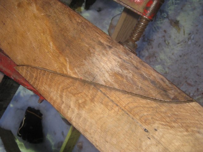
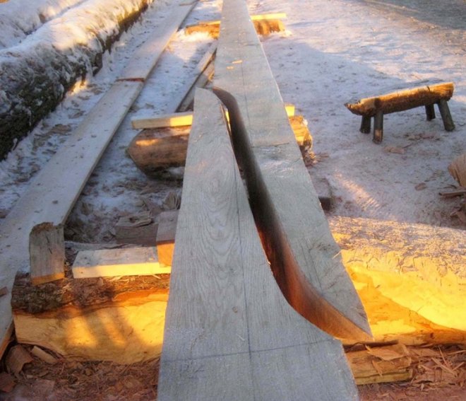
On closer inspection of the photos, and others I've collected from the interwebs for these same parts, all the scarphs follow the same basic pattern and can be approximated.
The next question is, can these shapes be made on a CNC machine?
-
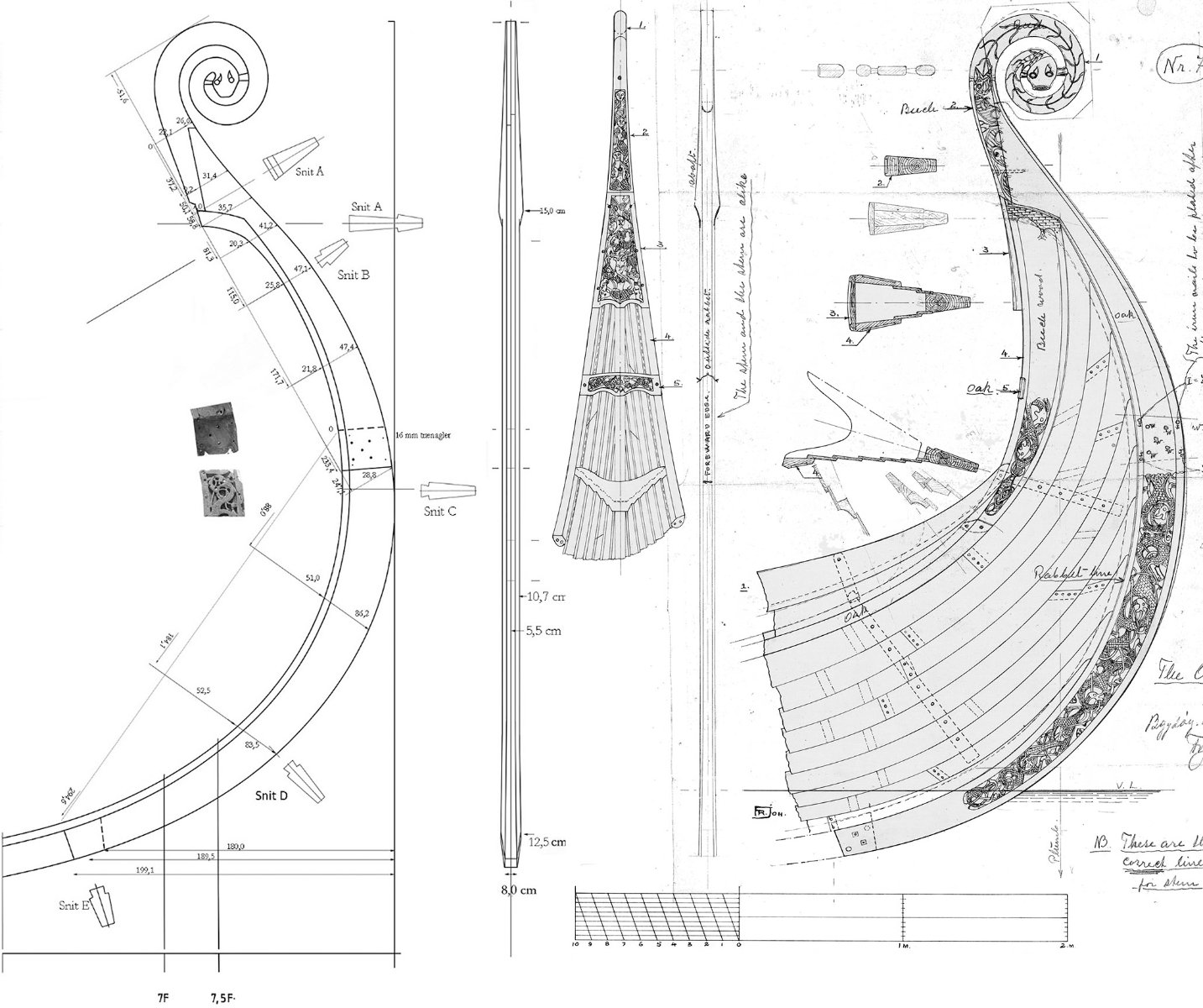
There are some good photos and descriptions here by the master shipbuilder of Saga Oseberg, Mr. Thomas Finderup, about halfway down the page:
https://osebergvikingarv.no/osebergskipet/rekonstruksjonen-av-osebergskipet/
Specifically these images:

- GrandpaPhil and mtaylor
-
 2
2
-
Is it scarph or scarf, I can never tell, I use ph usually to differentiate from the neckware...
In any event, I cannot cut one to save my life. I'm so bad at cutting a simple angled scarph that I gave up entirely at one point and tried to build this section out of alternating layers of thin strips of wood built up bread and butter style to thickness, and then interlocking with the next part like legos. Unfortunately it was no stronger than a regular butt joint in practice, and snapped off when gluing the loten to the aft stem...
-
-
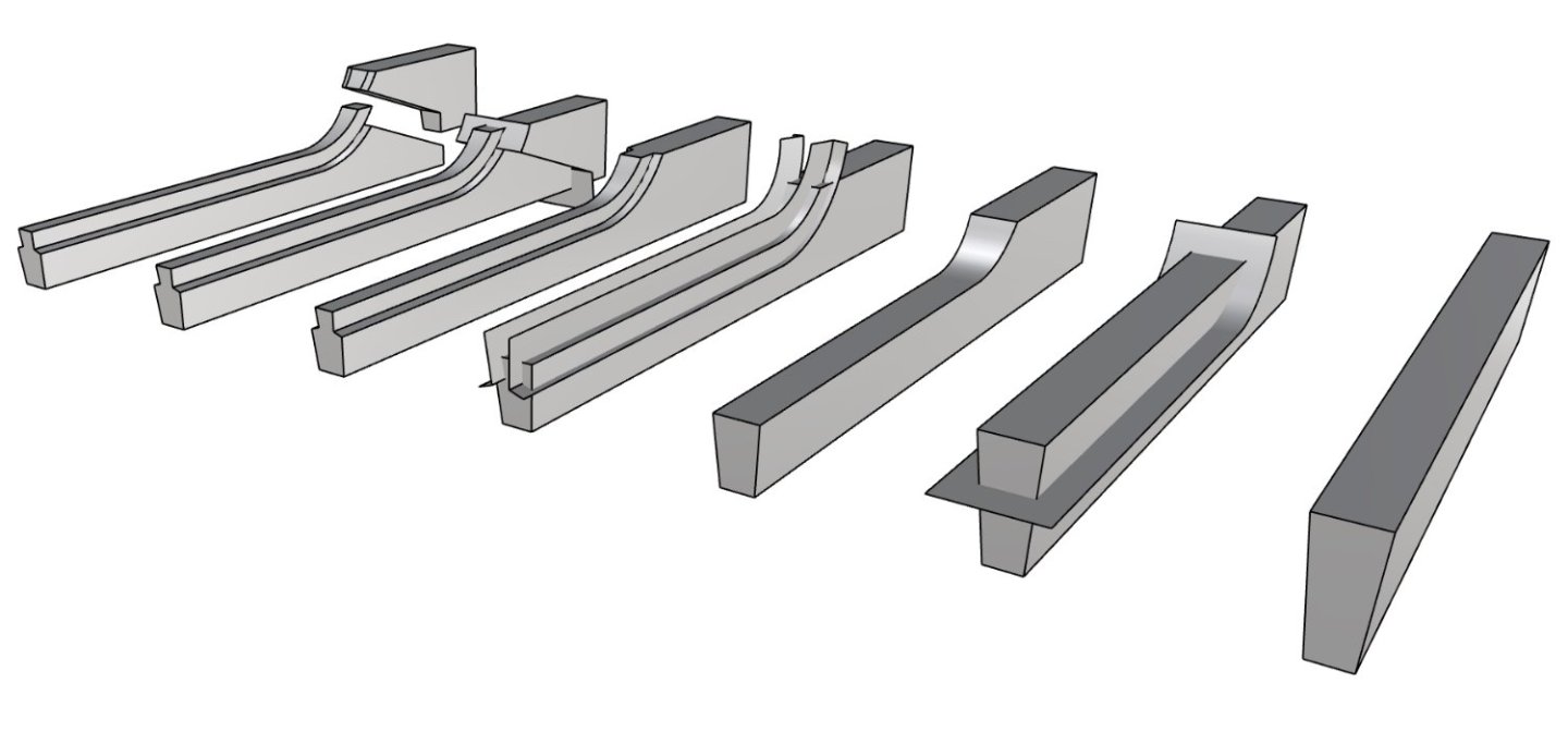
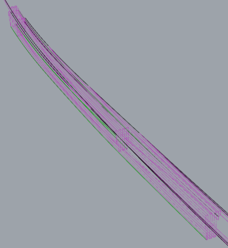
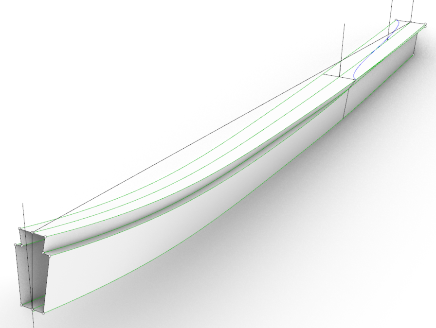
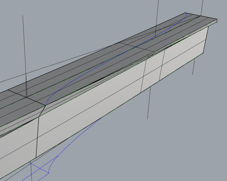
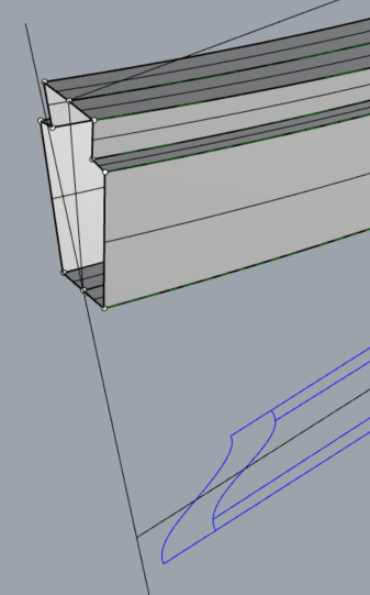
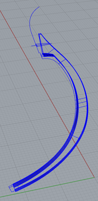
Here's the nearest I can figure in 3D. The plans in the PDF are slightly distorted so cannot be modeled as drawn, but when I work from the math I get something like this. I can project the long scarf from the top view though it doesn't quite line up, but I've no idea how to project it on to the bottom view. The short scarf doesn't line up at all.
- GrandpaPhil and mtaylor
-
2
-
This should be safe since I drew all lines myself. Welcome to the "Loten", also referred to as "Lot" in some references. It's the aft segment of the keel, used when the keel length exceeds available tree heights, I'm guessing. It's the single most confusing shape on the ship.

This corresponds to pages 26 and 27 of "Rekonstruktion af Osebergskibet Bind II" by Vibeke Bischoff
-
-

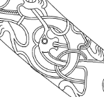
Redoing Oseberg
in CAD and 3D Modelling/Drafting Plans with Software
Posted
So many carvings to get into the right format. This will take a while...