KrisWood Posted September 5, 2022 #1 Posted September 5, 2022 Hi all! Some of you may already be familiar with my much troubled scratch build of the Oseberg Ship (working from these plans). With my wood tools indefinitely in storage and without a license for Rhino at the moment, I'm on the lookout for free alternatives. The end goal will be to have the parts milled from the 3D files at some point in the future. This begets three questions: 1. What is the best free hull / part modeling software available. 2. Can this software model clinker hulls? 3. Can this software import Rhino files? Currently at the top of my shortlist is Delftship, which can certainly model hulls, though I don't know about parts or clinker planking. I'm having a hell of a time just getting acclimatized to the interface at the moment. Next up I'll try Fusion 360, which looks more familiar given I started in 3dsmax and Autocad many years ago, but still foreign to my more recent Rhino experience. I'd love any suggestions. thibaultron and mtaylor 2
Kevin-the-lubber Posted September 5, 2022 #2 Posted September 5, 2022 Hi Kris Well, F360 is free for hobbyists. It has it's foibles and can be frustratingly clunky at times but I've managed to find ways to do everything I've wanted so far, including clinker hulls (screengrab below), despite on many occasions saying I was going to properly try Rhino with a view to switching. Declaration of self-interest here, I'd love someone who has used both tools to give an objective appraisal so I know if Rhino is worth the learning curve and cost! (These boats are a work in progress but they print fine) I don't know if it can import rhino files but it can certainly import .fbx files. Though working with these is a bit of a PITA as they come through as meshes. I suspect you really won't need this but I found this F360 tutorial very helpful to get going quickly https://diyodemag.com/education/exploring_3d_part_1_beginners_guide_to_fusion_360 Good luck, it would be good to hear what you land on, what it's like etc. I've just had a pretty quick skim through your build log and FYI, I've initially lofted each strake separately as F360 can give you the runaround with lofting if the profiles are too complex (relatively speaking) but I'm no expert on this. Just noted that you look like you've lofted as whole station profiles on yours. I'll try to find the time to read your log properly over the next week as you seem to have run into problems with Rhino but here's a link to a man who can almost certainly help you there thibaultron and mtaylor 2 Kevin https://www.ebay.co.uk/usr/ktl_model_shop Current projects: HMS Victory 1:100 (Heller / Scratch, kind of active, depending on the alignment of the planets) https://modelshipworld.com/topic/23247-hms-victory-by-kevin-the-lubber-heller-1100-plastic-with-3d-printed-additions/ Cutty Sark 1:96 (More scratch than Revell, parked for now) https://modelshipworld.com/topic/30964-cutty-sark-by-kevin-the-lubber-revell-196 Soleil Royal 1:100 (Heller..... and probably some bashing. The one I'm not supposed to be working on yet) https://modelshipworld.com/topic/36944-le-soleil-royal-by-kevin-the-lubber-heller-1100-plastic/
KrisWood Posted September 5, 2022 Author #3 Posted September 5, 2022 The problems with my build were not with Rhino itself, except that it isn't free and I don't have access to it anymore. My problems were mainly with lacking the skill and depth perception to make the parts by hand. Once I'm up and running again, the goal will be to make files suitable for CNC mill or laser cutting so that once I can afford one, or find somewhere that can make the parts, I can use them to get all the parts cut out. mtaylor and thibaultron 2
Kevin-the-lubber Posted September 6, 2022 #4 Posted September 6, 2022 You could always do what I did, and take up 3D printing. It doesn’t have the same satisfaction as making something by hand but, if like me you can’t do that anyway, you still have the design challenges. mtaylor and thibaultron 2 Kevin https://www.ebay.co.uk/usr/ktl_model_shop Current projects: HMS Victory 1:100 (Heller / Scratch, kind of active, depending on the alignment of the planets) https://modelshipworld.com/topic/23247-hms-victory-by-kevin-the-lubber-heller-1100-plastic-with-3d-printed-additions/ Cutty Sark 1:96 (More scratch than Revell, parked for now) https://modelshipworld.com/topic/30964-cutty-sark-by-kevin-the-lubber-revell-196 Soleil Royal 1:100 (Heller..... and probably some bashing. The one I'm not supposed to be working on yet) https://modelshipworld.com/topic/36944-le-soleil-royal-by-kevin-the-lubber-heller-1100-plastic/
KrisWood Posted September 6, 2022 Author #5 Posted September 6, 2022 I’d like to work with wood. I just couldn't cut anything accurately to save my life. I'll save up for a mill and focus on design and assembling the parts. First though is figuring out which software to use. I tried Delftship and got as far as setting up one reference image. So far its interface is completely alien to me but I'll keep at it for a bit and see what I can come up with. thibaultron and mtaylor 2
KrisWood Posted September 7, 2022 Author #6 Posted September 7, 2022 (edited) I managed to get Rhino back up and running, so I'm going with that rather than trying to learn a new software package for now. That said, I've now got two goals: 1. Get my current Rhino files into a format suitable for CNC mill and/or 2. Get my current Rhino files into a format suitable for cutting out in card at a smaller scale While the former is certainly more exciting, as I'd get to build in wood, the latter is more feasible as I do not own a CNC milling machine and cannot afford one. I'd need a co-conspirator to help with the milling of the parts for the foreseeable future. My next question is, would anyone like to participate in a group project to (and / or give advice on how to) develop the plans into a mill-able / cut-able format? PS. I've already done most of the work, just need help figuring out where to go from here... Edited September 7, 2022 by KrisWood Kevin-the-lubber, GrandpaPhil and mtaylor 3
KrisWood Posted September 7, 2022 Author #7 Posted September 7, 2022 Ok first question for all you CAD / CNC folks out there: How would you model the S shaped scarphs between the keel segments? (Plan number 2, on page 26 of the plans linked in the first post) Not sure how I can include an image here for illustration without violating copyrights... mtaylor 1
mtaylor Posted September 8, 2022 #8 Posted September 8, 2022 2 hours ago, KrisWood said: Ok first question for all you CAD / CNC folks out there: How would you model the S shaped scarphs between the keel segments? (Plan number 2, on page 26 of the plans linked in the first post) Not sure how I can include an image here for illustration without violating copyrights... Crop the image down a bit to focus on the joint although Fair Use does allow for posting images/text for discussion, etc. Mark "The shipwright is slow, but the wood is patient." - me Current Build: Past Builds: La Belle Poule 1765 - French Frigate from ANCRE plans - ON HOLD Triton Cross-Section NRG Hallf Hull Planking Kit HMS Sphinx 1775 - Vanguard Models - 1:64 Non-Ship Model: On hold, maybe forever: CH-53 Sikorsky - 1:48 - Revell - Completed Licorne - 1755 from Hahn Plans (Scratch) Version 2.0 (Abandoned)
CDR_Ret Posted September 8, 2022 #9 Posted September 8, 2022 25 minutes ago, mtaylor said: Crop the image down a bit to focus on the joint although Fair Use does allow for posting images/text for discussion, etc. And make sure you provide clear attribution in your text, and even a link to the original source. Terry mtaylor 1 Current project: Reconstructing plans for Matthew Turner's brigantine Galilee
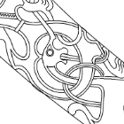
KrisWood Posted September 8, 2022 Author #10 Posted September 8, 2022 (edited) This should be safe since I drew all lines myself. Welcome to the "Loten", also referred to as "Lot" in some references. It's the aft segment of the keel, used when the keel length exceeds available tree heights, I'm guessing. It's the single most confusing shape on the ship. This corresponds to pages 26 and 27 of "Rekonstruktion af Osebergskibet Bind II" by Vibeke Bischoff Edited September 8, 2022 by KrisWood mtaylor 1
Waldemar Posted September 8, 2022 #11 Posted September 8, 2022 (edited) By following the advice of Mark and Terry, you can safely quote even very large parts of a cited work. Is that what you are asking? If so, divide larger pieces only as the last step in designing the entire model/vessel, if at all. Another strategy is to keep the uncut pieces as a safety copy. Edited September 8, 2022 by Waldemar mtaylor 1
KrisWood Posted September 8, 2022 Author #12 Posted September 8, 2022 Here's the nearest I can figure in 3D. The plans in the PDF are slightly distorted so cannot be modeled as drawn, but when I work from the math I get something like this. I can project the long scarf from the top view though it doesn't quite line up, but I've no idea how to project it on to the bottom view. The short scarf doesn't line up at all. GrandpaPhil and mtaylor 2
Waldemar Posted September 8, 2022 #13 Posted September 8, 2022 You can make it straight, i.e. vertical in this case, or if you a pedant like me make another curve at the bottom at its correct place and then make cutting surface by lofting these two curves. There are other methods possible, however, depending on the specific needs and possibilities. mtaylor 1
KrisWood Posted September 8, 2022 Author #14 Posted September 8, 2022 Yeah I tried the latter but it created some really weird geometry because the scarph curves as drawn do not line up with the mathematically derived keel mtaylor 1
Waldemar Posted September 8, 2022 #15 Posted September 8, 2022 (edited) I should add that closed polysurfaces (solids) are needed for Boolean operations. If your parts are open, you need to use the simple "split" or "trim" commands. Edited September 8, 2022 by Waldemar mtaylor 1
Waldemar Posted September 8, 2022 #16 Posted September 8, 2022 Well, you say "weird", I say "beautiful" 🙂 Ian_Grant and mtaylor 2
KrisWood Posted September 8, 2022 Author #17 Posted September 8, 2022 Is it scarph or scarf, I can never tell, I use ph usually to differentiate from the neckware... In any event, I cannot cut one to save my life. I'm so bad at cutting a simple angled scarph that I gave up entirely at one point and tried to build this section out of alternating layers of thin strips of wood built up bread and butter style to thickness, and then interlocking with the next part like legos. Unfortunately it was no stronger than a regular butt joint in practice, and snapped off when gluing the loten to the aft stem... mtaylor 1
Waldemar Posted September 8, 2022 #18 Posted September 8, 2022 I'm sure you can do it the right way, as it is in the original, especially since you've already put so much good work into your project. Sometimes I sacrifice a number of days for a trivial issues too. And remember to keep the uncut elements as backups. mtaylor 1
KrisWood Posted September 8, 2022 Author #19 Posted September 8, 2022 There are some good photos and descriptions here by the master shipbuilder of Saga Oseberg, Mr. Thomas Finderup, about halfway down the page: https://osebergvikingarv.no/osebergskipet/rekonstruksjonen-av-osebergskipet/ Specifically these images: mtaylor and GrandpaPhil 2
Waldemar Posted September 8, 2022 #20 Posted September 8, 2022 Do you see? It's not space technology or brain surgery, just diligence is required.... 🙂 mtaylor 1
Waldemar Posted September 8, 2022 #21 Posted September 8, 2022 One more technical detail: after creating the cutting surface (by lofting or by other means) it may be that it is shorter than required. Then simply you can make it longer by using the "extend surface" command. mtaylor 1
KrisWood Posted September 8, 2022 Author #22 Posted September 8, 2022 (edited) I guess you're right. It doesn't have to be exactly the curves used in the original ship, as long as it's close and serves the same purpose. (Even the replica, which sails just fine, doesn't always line up perfectly on every scarph) On closer inspection of the photos, and others I've collected from the interwebs for these same parts, all the scarphs follow the same basic pattern and can be approximated. The next question is, can these shapes be made on a CNC machine? Edited September 8, 2022 by KrisWood mtaylor 1
Waldemar Posted September 8, 2022 #23 Posted September 8, 2022 If you persist, they probably can. Yet, in this particular case, the level of complexity and effort required to do so would make it a hopelessly inefficient endeavour, and even more so for a one-off build. This is perhaps the last method I would consider.... Sorry. mtaylor 1
KrisWood Posted September 8, 2022 Author #24 Posted September 8, 2022 It seems bizarre to me that this problem might actually be more easily solved with technology the Vikings had available to them than with technology we have today. I started thinking about how I would solve the problem as a viking and it was intuitively obvious. I know the dimensions of the keel, including the depth of the rabbet, which I don't want the diagonal line to go through. All I need is a length of string a bit longer than the depth of the rabbet. Measure and mark that distance from one end of the scarph on the top of the keel. From that mark draw a circle with the string measuring its radius. Repeat on the other end of the scarph. Draw a straight line connecting the tangents of the two circles. Use the same ratio of keel width to circle radius to repeat the process on the bottom. I'll try it out in rhino after I get some sleep... mtaylor 1
scrubbyj427 Posted September 8, 2022 #25 Posted September 8, 2022 The piece you are tying to make will be almost impossible to cut as a solid at those angles/curve. The best way is to extrude your cutting curve as a surface along a perpendicular line or two lines, for example draw a perpendicular curve at the beginning and end of the cut and extrude the cutting surface “along two curves”, then simply split the open surface into two parts, copy the cutting plane and trim it at each end of the open surfaces to close the part. In regards to cnc cutting or even laser cutting, I think it is possible with a curve, im exploring this same problem with a design I am working on currently. You can see below that like your keel piece, I also had to cut on a curve, all the pieces are perpendicular to the camber. You can see the complexity of the cambered beams that require scarf joints as well as camber. If these beams were flat then it would be easy, however they are not, two options are one, to cut them flat and individually camber/bend each piece... or pre camber the subject wood board and laser cut. My theory is that if the wood to be cut is already curved (cambered deck beams in my case) then perhaps the router or laser can be programmed high enough (at top of camber/curve) to cut, yet not too high to miss the bottom of the curve, then what you are trying to accomplish is possible. I hope that made some sense... mtaylor 1 Current Builds: HMS Winchelsea 1764 1:48 - 5th rate 32 gun frigate (on hold for now) HMS Portland 1770 Prototype 1:48 - 4th rate 50 gun ship
Waldemar Posted September 8, 2022 #26 Posted September 8, 2022 (edited) I think Scrubby has already explained it very convincingly, but to give you still an additional warning of what you will be dealing with, let me say that it is not only about the geometry, but also about the actual machining of such long, curved, tapered and slender parts: You will have to precisely position such parts on the flat table, you will have to hold them fast all along their length so that they do not bent under cutter pressure, you will have to change your cutters to different shapes, you will have to reposition your parts on the table to machine all sides, you will have to "zero" your different cutters each time you modify your setup. All of this you will have to do with a very tight repeatability to get just the acceptable results. This would be a nightmare even for very experienced machinist. Edited September 8, 2022 by Waldemar mtaylor 1
KrisWood Posted September 8, 2022 Author #27 Posted September 8, 2022 (edited) For the CNC part, I had thought to: Use a sheet of wood a little more thick than the keel width. CNC four holes, one at each corner of the sheet so that it fits over guide posts Model the whole sheet with the keel turned on its side Have the CNC mill a little less than half the depth of the keel Flip the sheet over and mill the other side of the keel Then use an X-Acto knife to cut through the thin remaining wood around the keel, like the sprues on a plastic kit model. Would something like that work? Edited September 8, 2022 by KrisWood mtaylor 1
Waldemar Posted September 8, 2022 #28 Posted September 8, 2022 (edited) Depends on many factors which only you can anticipate. Say, the quality of the milling machine (like stiffness or repeatability) and the cutters themselves, the quality of your preparations and the actual work, like your ability to correctly program the CNC device, the right (or bad) setup of the part to be machined, the properties of the material to be milled (size, thickness, strength, stiffness) etc. The intricate shape of your keel (especially twisted surfaces) would probably require several passes of a cutter of quite small diameter, which would leave steps anyway. Still, if you feel you must try, go for it, at worst (or best) you will gain experience. Edited September 8, 2022 by Waldemar mtaylor 1
Kevin-the-lubber Posted September 8, 2022 #29 Posted September 8, 2022 I don’t know if this will be at all helpful as I sense you really do want a true scarf joint; but me, I would fake it, and engrave the lines into the wood. (Actually, since I 3D print everything, I would just design them in). I don’t know how rhino works but in f360, if I wanted a true scarf, I would loft one part from top to bottom using guide rails, then cut the matching half with the lofted one and probably offset the face of one of them by a little for a bit of clearance. mtaylor 1 Kevin https://www.ebay.co.uk/usr/ktl_model_shop Current projects: HMS Victory 1:100 (Heller / Scratch, kind of active, depending on the alignment of the planets) https://modelshipworld.com/topic/23247-hms-victory-by-kevin-the-lubber-heller-1100-plastic-with-3d-printed-additions/ Cutty Sark 1:96 (More scratch than Revell, parked for now) https://modelshipworld.com/topic/30964-cutty-sark-by-kevin-the-lubber-revell-196 Soleil Royal 1:100 (Heller..... and probably some bashing. The one I'm not supposed to be working on yet) https://modelshipworld.com/topic/36944-le-soleil-royal-by-kevin-the-lubber-heller-1100-plastic/
KrisWood Posted September 8, 2022 Author #30 Posted September 8, 2022 Re-reading volume 1 of Ms Bischoff's work, she explains that the scarfs are not only S shaped, but TWISTED, so that no part of the top S curve is parallel with any part of the bottom S curve, thus creating interlocking curves. 🤪 mtaylor 1

Recommended Posts
Create an account or sign in to comment
You need to be a member in order to leave a comment
Create an account
Sign up for a new account in our community. It's easy!
Register a new accountSign in
Already have an account? Sign in here.
Sign In Now