MAGIC's Craig
-
Posts
135 -
Joined
-
Last visited
Content Type
Profiles
Forums
Gallery
Events
Everything posted by MAGIC's Craig
-
 And to you, Keith. Thank you for for following along. I have been doing a variety of little, mostly-non-visible projects on TWILIGHT, however I will post progress in the next week or so.
 -
I have been away a bit. Delighted to find a notification about Lula.. but I'm gobsmacked to see what you have accomplished and especially in such a scale! Once again, you are kindly showing all of us what can be accomplished with some care (and desire).
- 732 replies
-
- 4
-

-

-
- Lula
- sternwheeler
- (and 1 more)
-
Fascinating techniques and lovely results from your careful workmanship. I find myself learning all sorts of new ideas. thanks for sharing the build process. Craig
-
Thank you, John. I'm honored that this sort of craft has caught your eye (and the eyes of others as well.) Will endeavor to keep up the standard. 😉 Craig
-
Thank you for the compliment, Mark. It is fun to have something one thought about, eventually drew up (and had to shelve) begin to take a more physical presence in the "shop". And I am also pleased that this sort of work earns praise. It is an enjoyable hobby with much still to learn by doing. Craig
-
Thanks, Keith. I spent a bunch of time thinking about carefully framing and then building each unit as if I were building them full-size... however, eventually, the back brain hammered on the door to the front brain to say that carving and gouging out some blocks of wood would be far simpler and quicker. When I woke up that morning, it just seemed like a better idea when working at this scale.
-
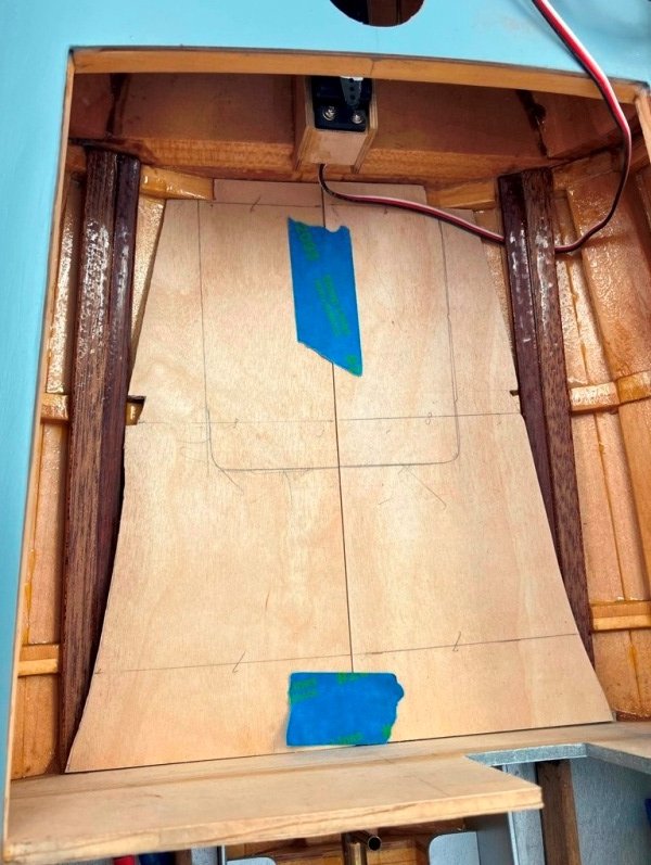
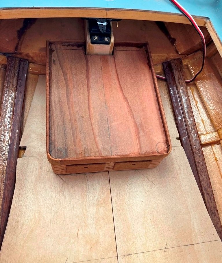
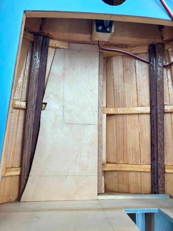
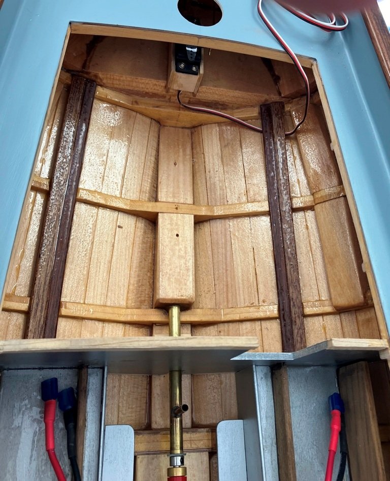
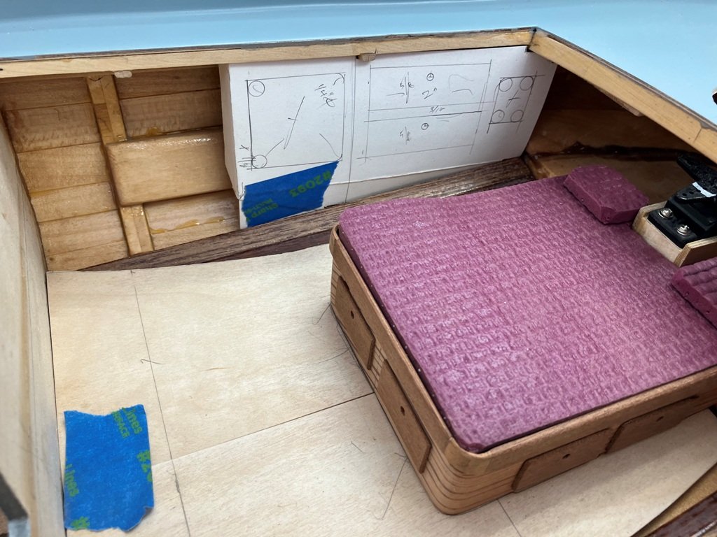
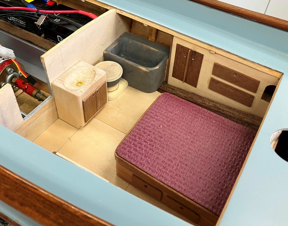
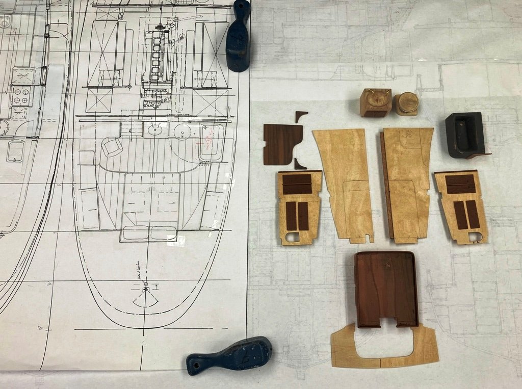
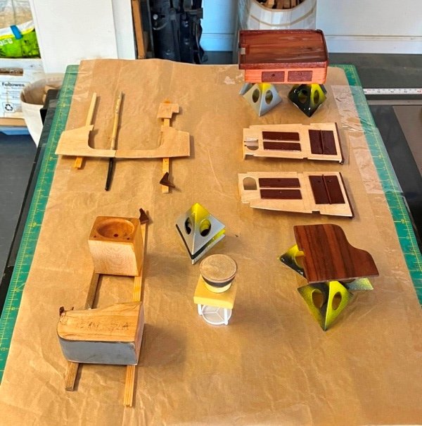
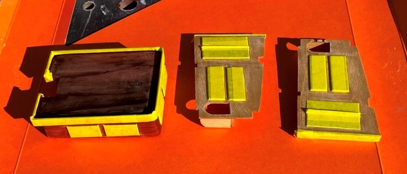
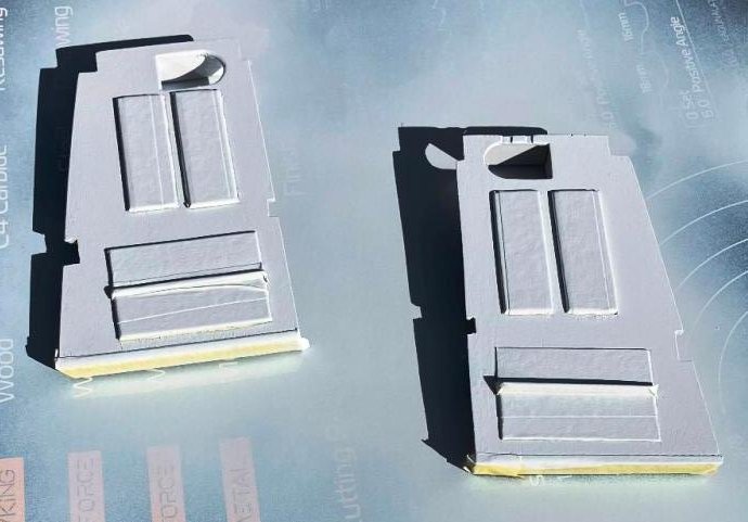
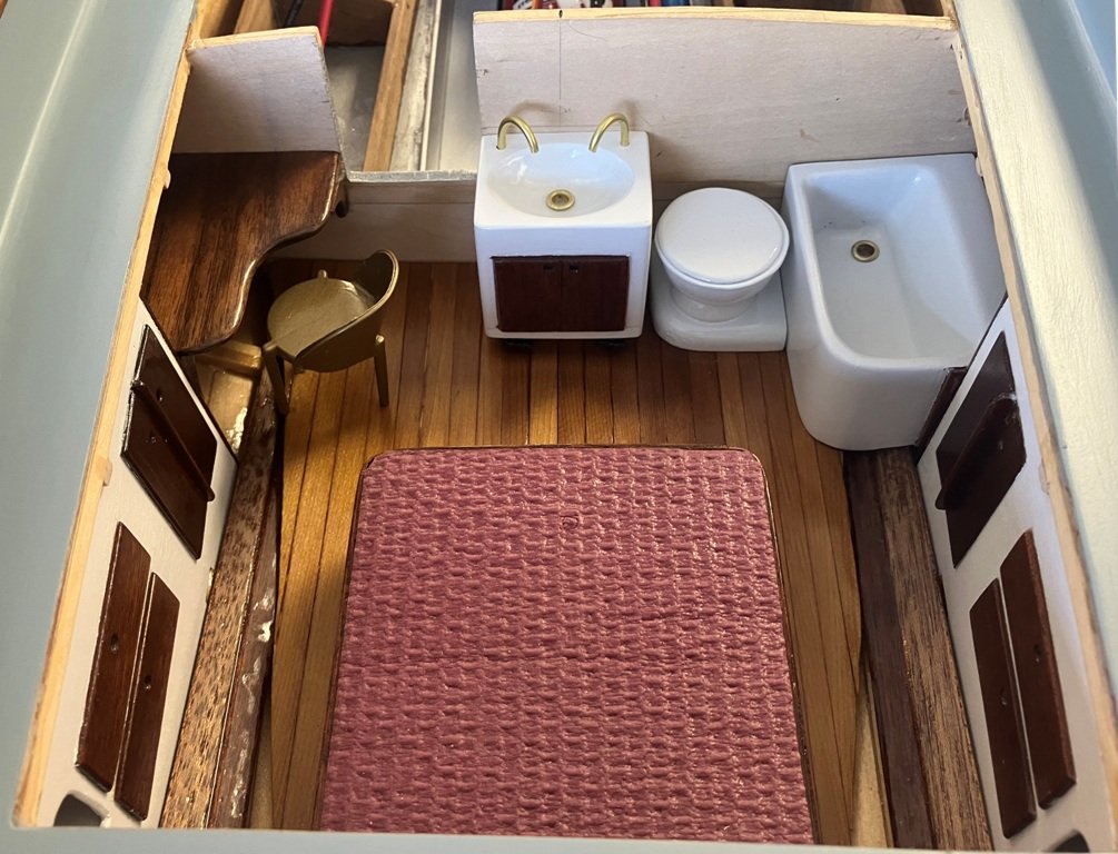
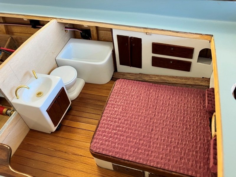
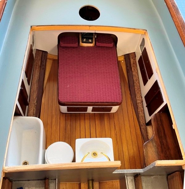
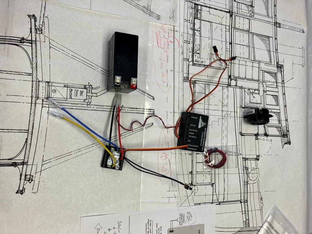
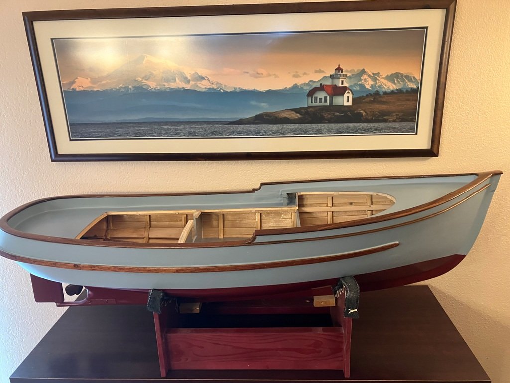
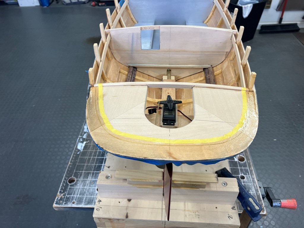
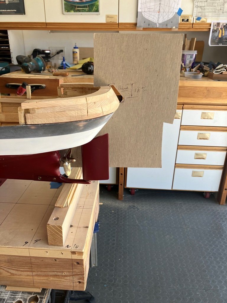
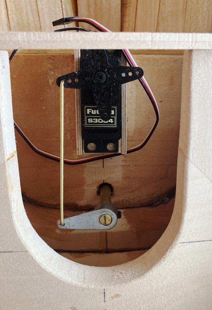
First of all, my heartfelt thanks to all who have dropped by and left comments. I find that your presence and well wishes are good motivators to moving forward on this craft. November. 2024 update: I did cobble together the various R/C components - sometimes with longish temporary lengths of wiring - to "dry run" the set-up. It was a pleasant surprise to activate the transmitter, turn on the receiver, switch on the electronic speed control (hereinafter referred to as the ESC) and discover that the rudder worked and the prop spun in both directions. However, as it turned out, (because of my poor soldering technique), the attached sound module did not make any noise. With the kind troubleshooting assistance of Nick Scalone at Harbor Models, the problems were discovered. Once I corrected the bad connections, the engine "rumbled " to life, the horn worked and the bell rang! With that trial completed, it was time to go back to building up the model. My focus was to first develop the joinery and furniture of the aft cabin area. Like most stern areas, the hull curvature and converging structures of the aft portion of the hull required a bit of pattern making to make the most of the space prior to shaping wood. Card material was cut to fit a time (or three) before the 1/16" th. 3-layer ply could be cut out. The major furniture in the cabin is the bunk but this model's bunk required a notch-out to accommodate the rudder servo. Side panels for the joinery were laid out on fitted pieces of card. Various blocks of basswood were carved or scooped out or assembled to represent the tub, WC and vanity and then temporarily slipped into place. A piece of no-longer-used yoga mat became a mattress. Mahogany drawer faces and cabinet doors were fashioned and glued in place. A lovely piece of walnut was made into the desk top. The process continued pretty well according to the plan. The cabin sole was planked with 1/16" WRC strips and varnished. The various components had their respective mahogany/walnut joinery varnished. Once the varnish was dry, those pieces to also be painted were masked off and sprayed. All of the bits were then assembled in place to give you a look at the (nearly) finished appearance in the aft cabin. I will next probably move on to the commencement of the main cabin and pilothouse in order to begin work above the level of the main deck. So, until again, Craig
-
Thanks for the compliment, Peter. While a shoulder replacement revision surgery has slowed progress over the past couple of months, I am pleased with the general development of this imagined craft and look forward to working out not only the interior joinery, but also figuring out how to tuck the necessary R/C equipment and wiring away unobtrusively as possible yet to still be accessible. A fun challenge! And while I am at it, a tip of the "thank you" hat to both Keith Black and Roger Pellett.
-
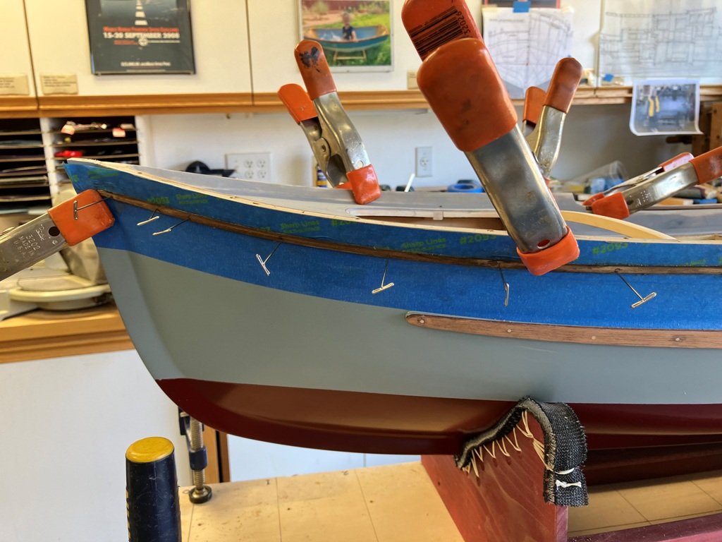
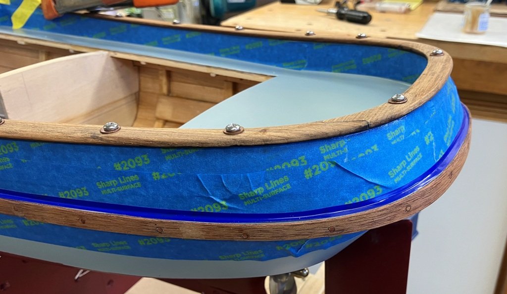
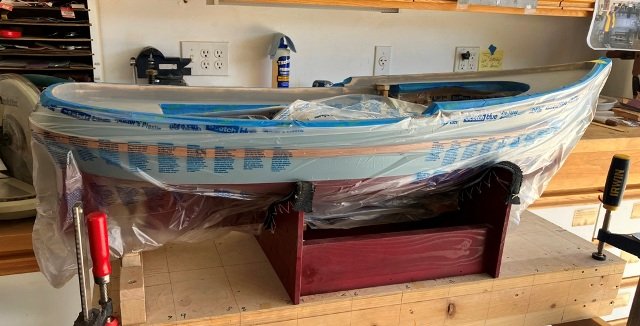
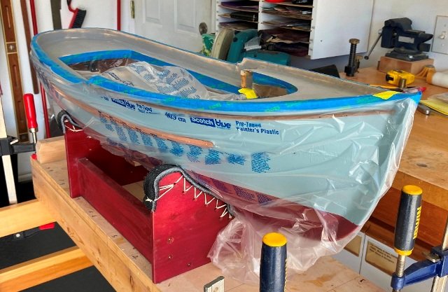
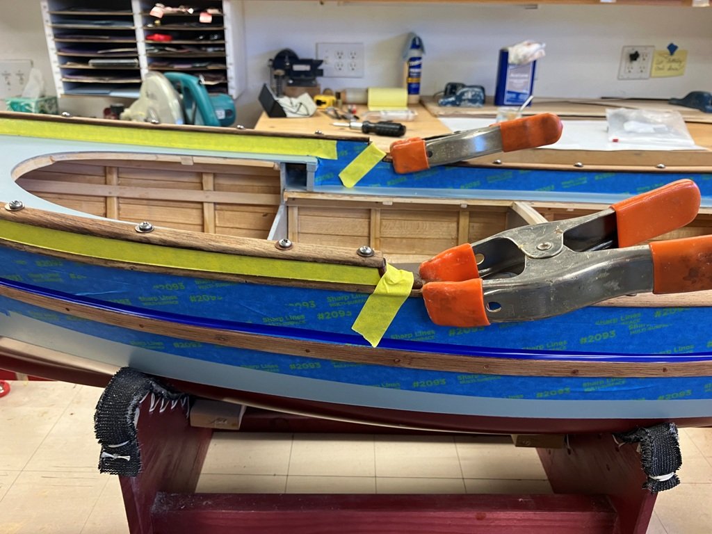
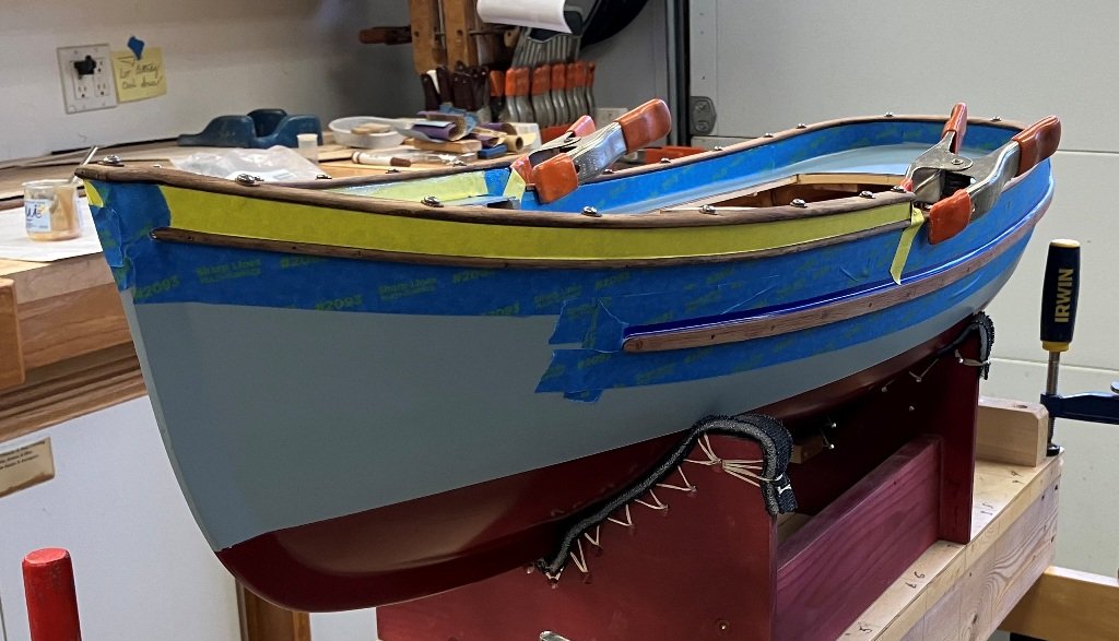
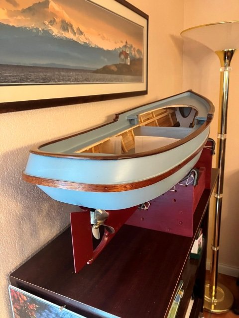
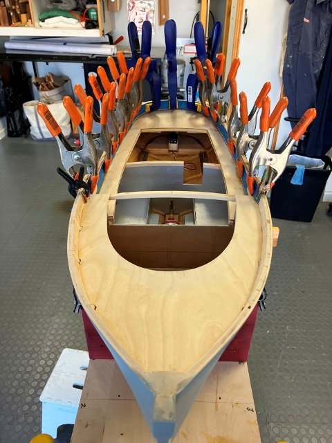
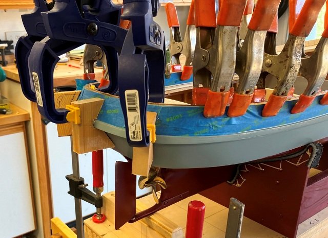
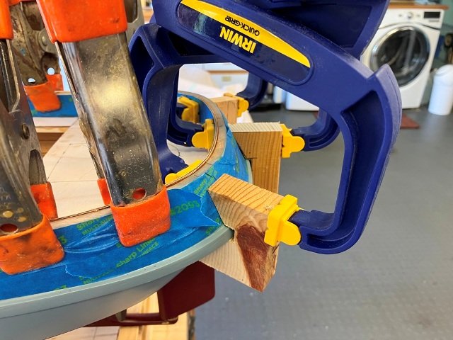
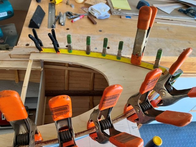
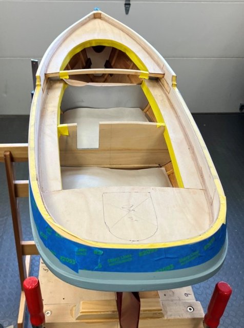
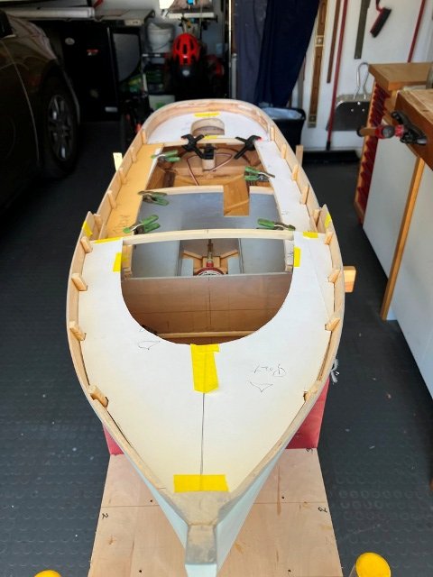
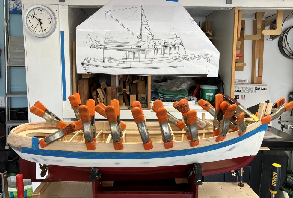
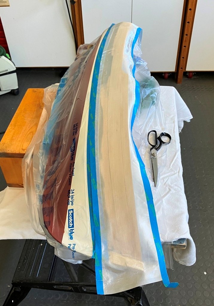
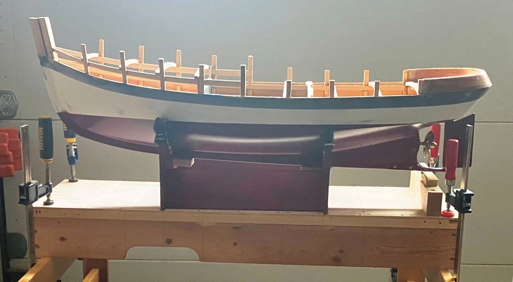
When the deck and bulwarks were sanded and ready for painting, I thought that fitting the upper rubrail at this point would simplify later varnishing. Fortunately, "T" pins and a few clamps were sufficient for clamping the rails in place. Once the rails were secured, the exterior of the hull as well as the open cabin interior were taped and masked off to permit spray- painting the primer and Tamaya acrylic topcoats onto the decks and bulwarks. Once painted, the film masking was removed and additional tape masking placed to protect the hull during the installation of the teak bulwark caprails. The cap rails were temporarily screwed down to the bulwarks while the epoxy cured. After the glue set, the screws were removed and the holes bunged with bamboo treenails. The treenails were cut off nearly-flush with the rail tops, sanded fair and then the end-grain lightly dyed using a furniture color touch-up pen. The caprails were initially given 4 coats of semi-gloss varnish to carry them through the future wear-and-tear of model building. I will finish up this update with a few photos of the painted and varnished hull as of September 22, 2024. Until again, Craig
-
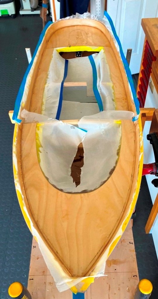
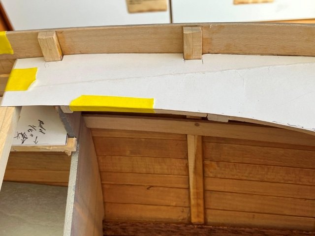
I decided to fill the between-frame spaces of the bulwarks with blocking of basswood and then, after fairing, skin the inner face of the bulwark with more of the 1/16" ply. The intersection of the deck and bulwark inner face was planned to be filleted with an epoxy mix prior to sealing the decks and bulwarks with fiberglass. The side deck bulwark faces and the stern bulwark face were glued in in one session. The stern inner face was a bit of a challenge to clamp tight to the existing stern structure. The foredeck bulwark strips quickly followed a similar procedure. Vinyl tapes were then utilized along the deck and on the inboard sides of the bulwarks. These defined the limits of the fillets which were to be shaped to ease the transition from horizontal to vertical of the fiberglass cloth and epoxy waterproofing layer. Once the fillets cured, they were faired to a cove shape. Lightweight fiberglass cloth was cut and fit to cover the decking and the inboard faces of the bulwarks. It was epoxied in place and when cured, given an additional two coats of an epoxy fairing mix in preparation for priming and painting. Rest assured, it was sanded fair and smooth. 😉 I will continue with the tale later this evening.
-
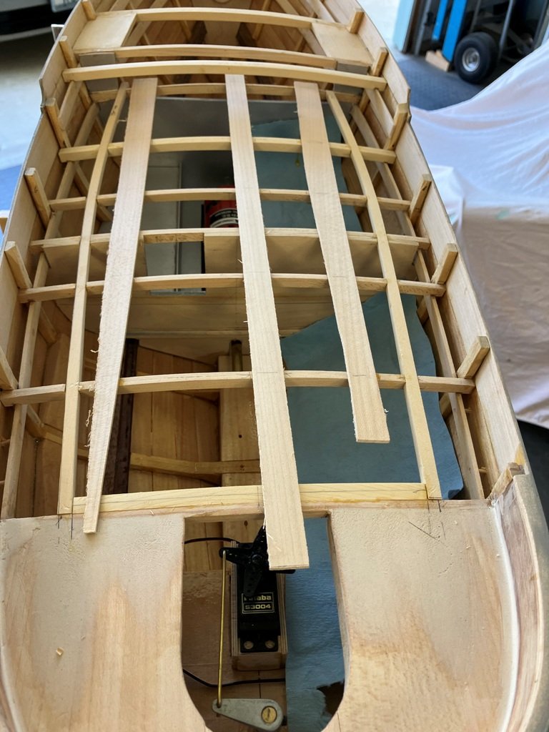
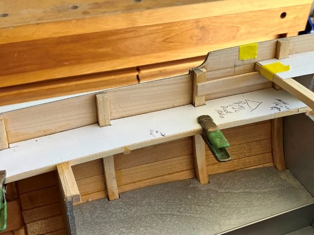
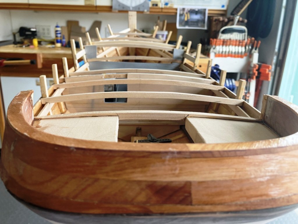
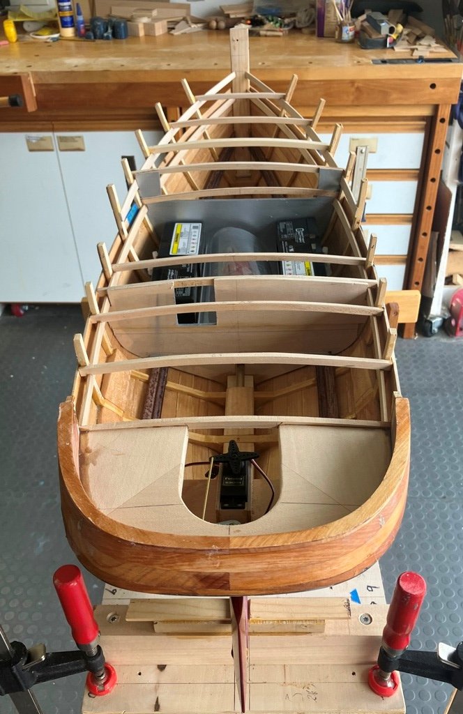
It has been a couple of months since the last posting, so I will endeavor to bring those who are following the build of TWILIGHT up to date. The next sequence commences with the fitting of the deck carlins for the house along with some centerline blocking on the foredeck. The carlins were half jointed to the deeper beams and once glued in place, the inboard portion of the deck beams were cut away. Card (paper) patterns were cut and fitted around the frames for the two side decks, the stern deck and the raised foredeck. A Trial fit of the ply pieces also permitted checking on a method for clamping/holding the ply into the required (faintly compound) curves. With this sequence established, the 1/16" 3-ply baltic birch plywood was glued to the deck beams and carlins. The finishing of the construction of the bulwarks is next.
-
She's looking lovely and, even better, quite fair. An inspiration to us all.
-
I share your hopes and I have also been discussing this whole "climb all over a model" thing with our current feline, Ballou. She will, on occasion, flick an ear at me while I am speaking to her. I suppose that is as much as I might best hope for. Thank you for the compliment on the finish. Craig
-
Thanks, Keith Black. It is surprising to me how often a model (or half-hull) allows one to see overall details better than the full-size version.
-
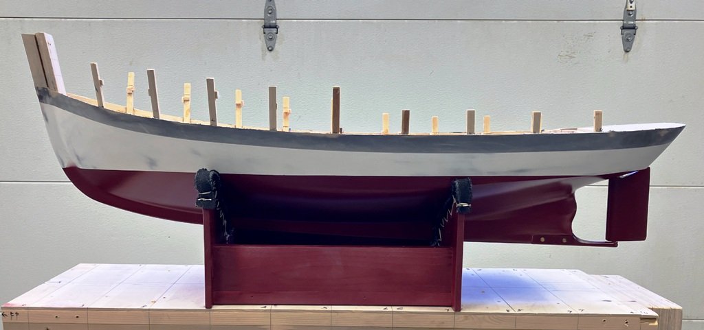
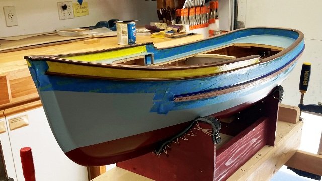
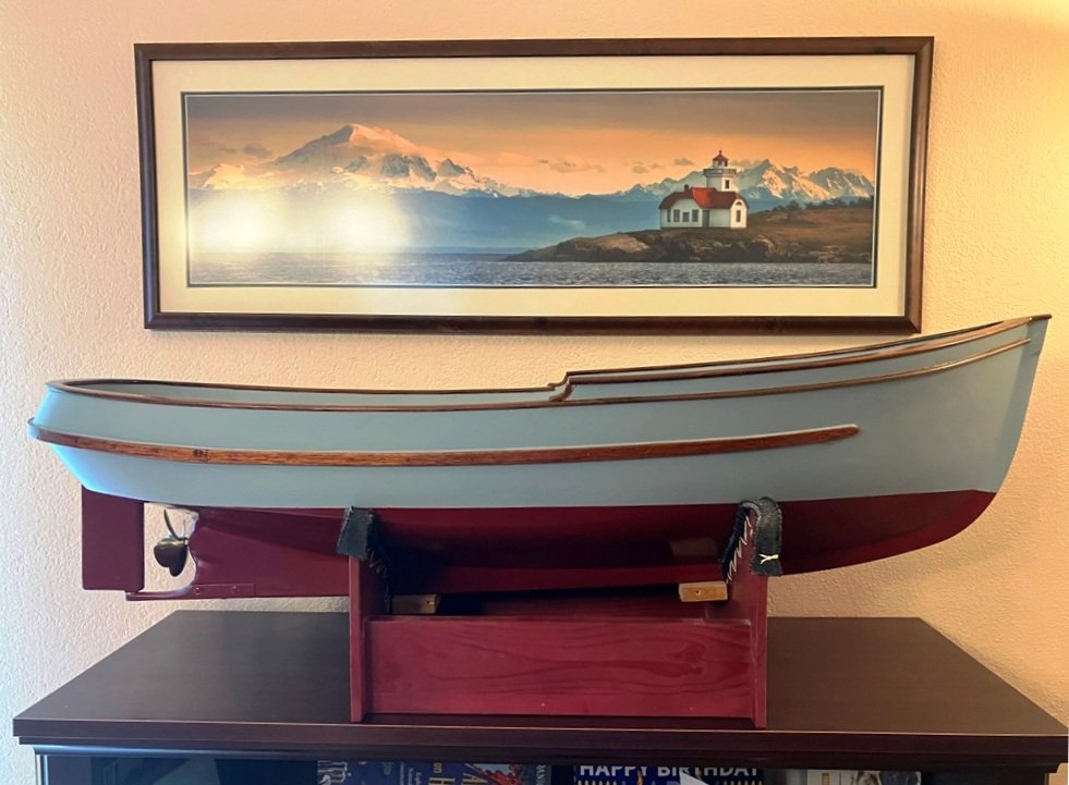
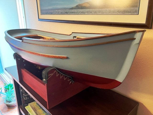
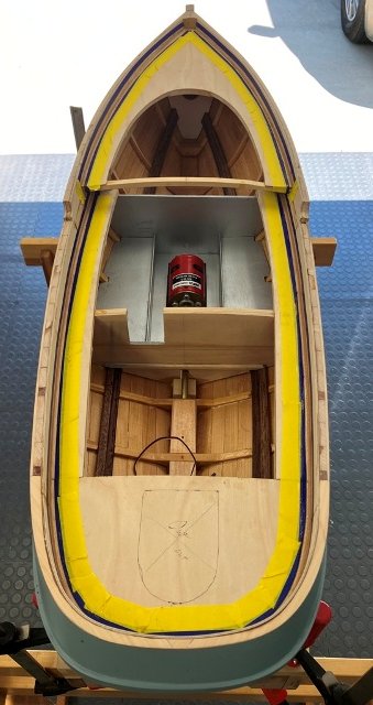
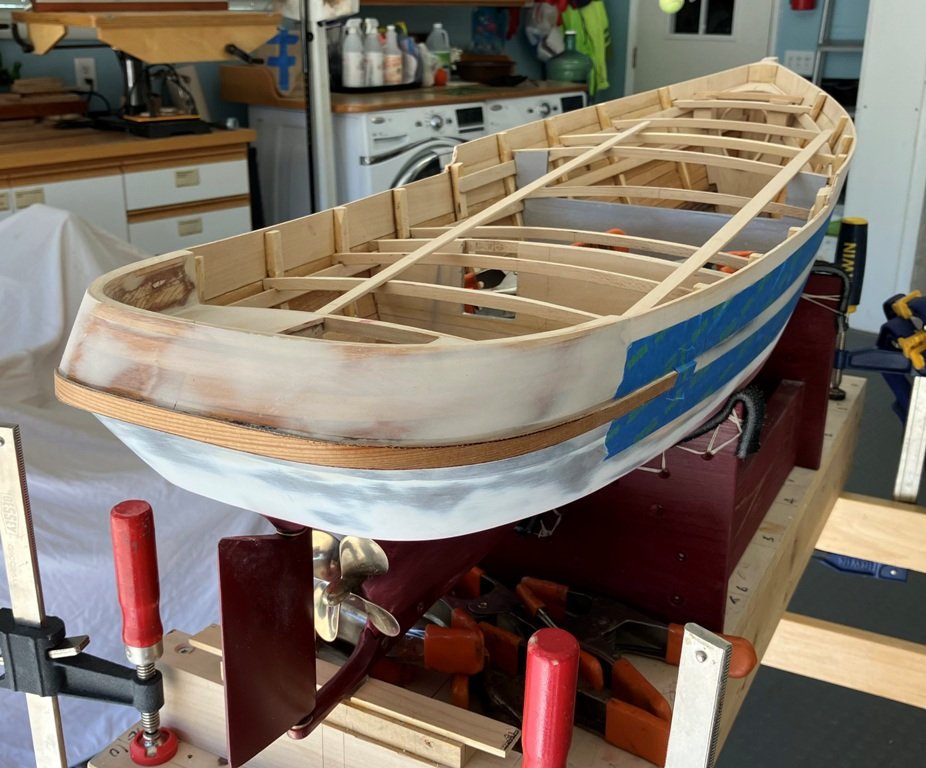
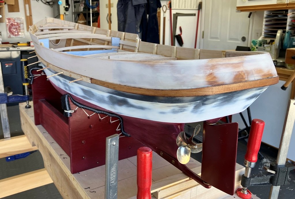
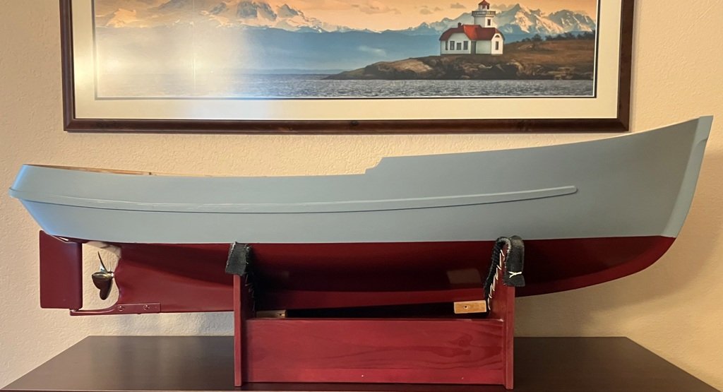
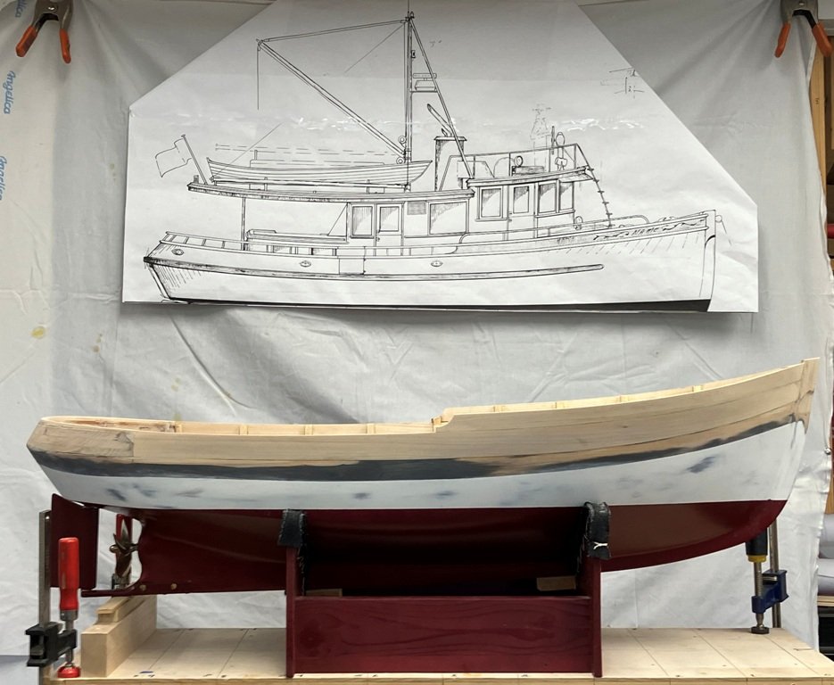
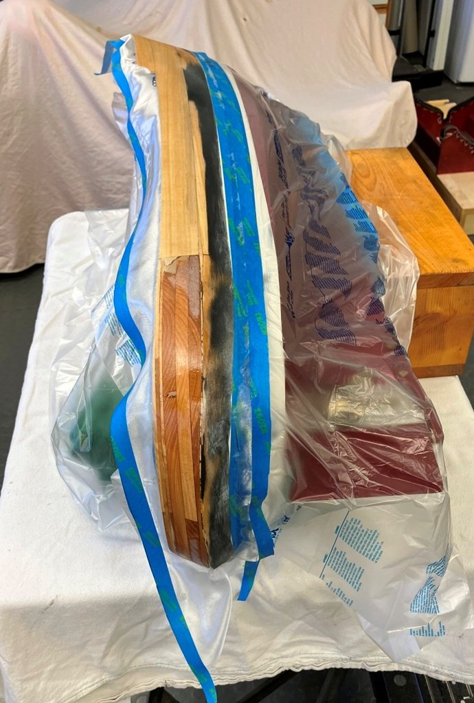
I apologise about the last photo, which for some reason I cannot delete from that post. It belongs here: The stern portion of the sponson to support the hardwood rub-rail was laminated from 1/16" thick red cedar around the stern against small wooden wedges glued to the hull. The sponson sides were gotten out of 1/8" thick basswood strips, tapered slightly, then glued and doweled to the hull sides. Having grown tired of looking at a "splotchy"-looking hull, it was deemed time to do some priming and painting before moving on to decking and interior construction. the hull of TWILIGHT was sanded, masked and primed, sanded some more (one never does enough of this, right?) and then given a couple of fresh color coats of paint. She was brought inside and given a trial fit for a possible display location. Until later, Craig
-
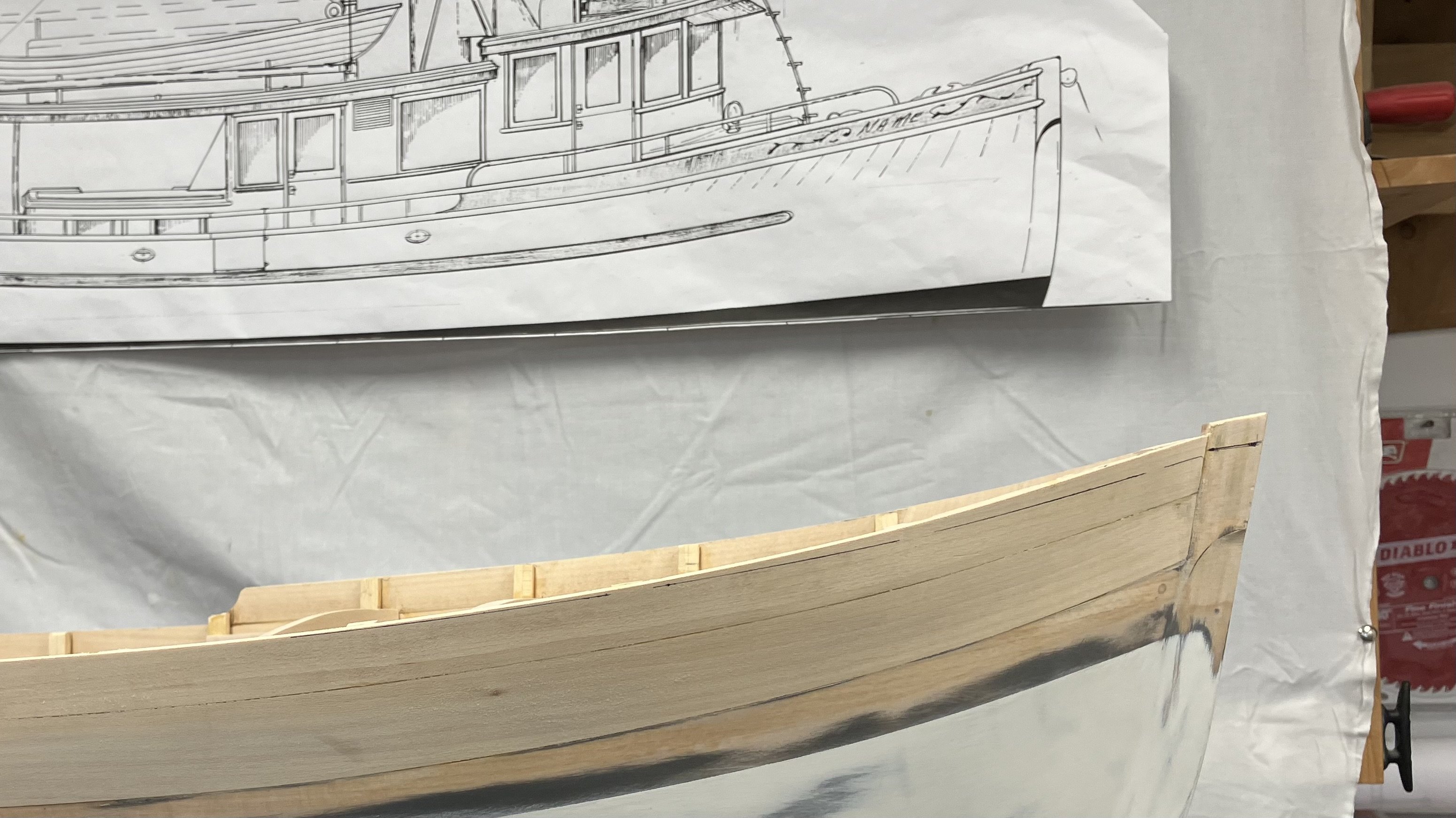
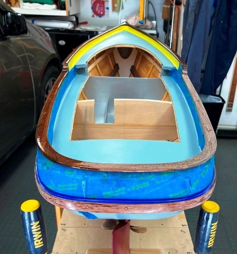
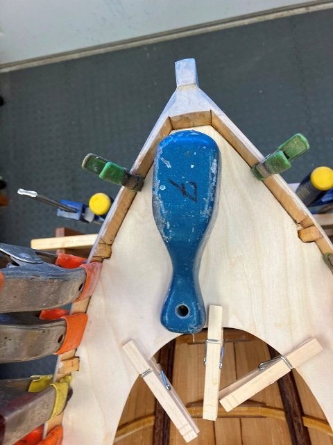
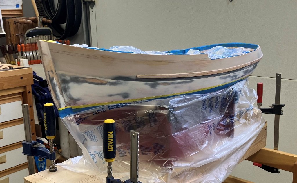
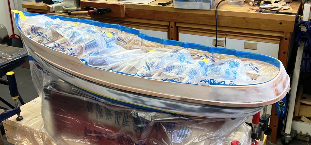
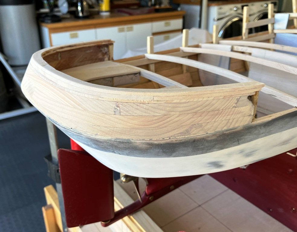
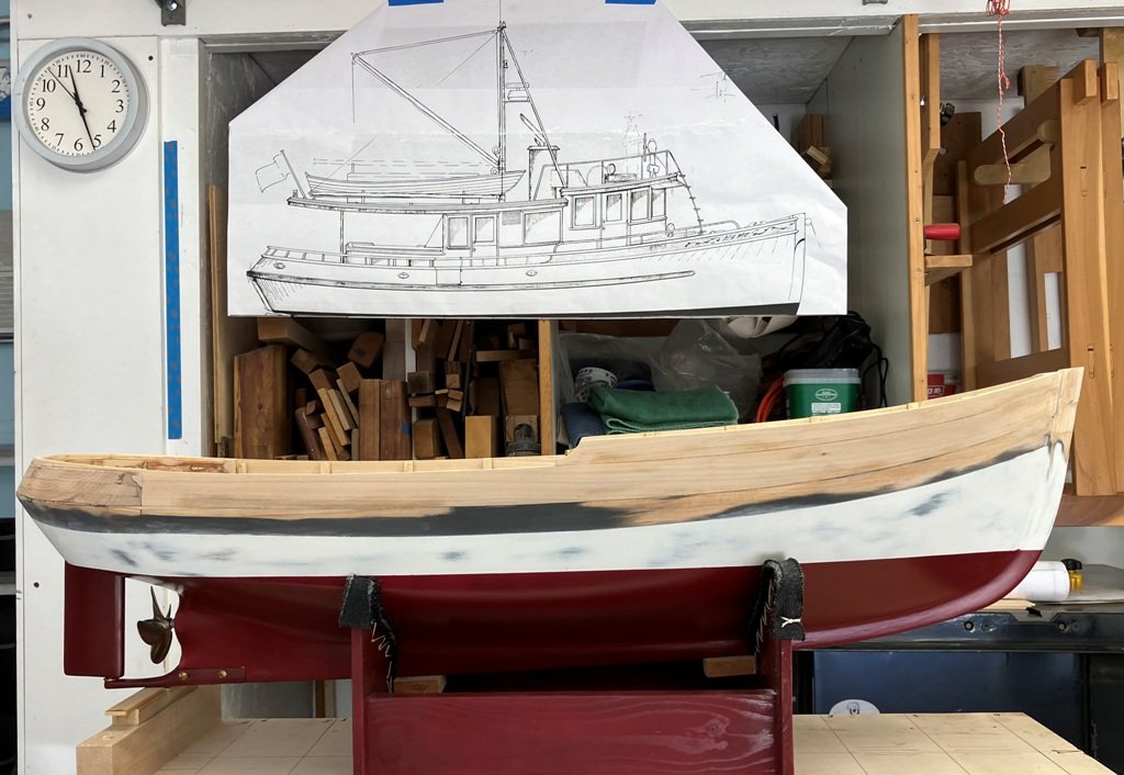
Over the past weeks, the planking of the bulwarks and bow rail were glued in place, faired to the existing hull, the stem was detailed and a revision was made to bow rail: When I viewed the photo above, I (finally) got "far enough from the trees to see the forest" to realized that there was a discrepancy between the profiles of the bow in the drawing and that of that of the actual model. The model's bow "kited-up" excessively to my eye compared to the earlier version of the bow as drawn above it. I used a batten to mark a revised bow profile on the model and decided to ponder the potential change while we were away on a trip. Upon our return from Duluth, MN, the proposed revision still looked to be useful (the deck structure forward would require some fairly major surgery/rebuilding to flatten the sheer further), so out came the fine saw and planes to trim it down. The next task was to cover the newly added upper planking with F/G cloth and epoxy to seal it to the existing hull. The cloth was epoxied on, the weave given a couple of coats to fill the weave and for fairing purposes and then it was time to glue on the rub-rail "sponson" (or base) prior to painting. (I will break up this posting into another to keep sizes in check).


-
Ahoy, mates...from central California
MAGIC's Craig replied to Capt. Kenway's topic in New member Introductions
I add my welcome as well. My wife and I live in Los Osos, near the south end of Morro Bay and extend an invitation should you get out this way to stop by. PM for info. -
What a treat it is to see your post and learn that you are back again! Thanks for the update.
-
Good morning: I would be delighted to have that opportunity. Please let me know when it works for you. Craig
-
No. We're in Los Osos
-
We also like to use Laguna Lake from that last ramp and float. When the lake level is up, we could trolley launch our schooner, which has a draft of 32" and sail her over a goodly portion of the lake.
-
I will be following along with your R/C progress since I would like to get a better appreciation for the wiring sequence as well as the "do's and don't's" as I build the system into my current build. Since home for me is relatively close to yours, I look forward to perhaps seeing your project underway. Very nice work!
-
My thanks to you, John, Jerome and Keith for the compliments and to all who show their appreciation. I am enjoying the build process - it sometimes stretches the mind to come up with solutions to whatever the day's building challenge is - and deriving the sequence of the presentation of photos in the blog helps me organize what should logically (?) follow. The quality of your works serve as guideposts to us all. Craig
-
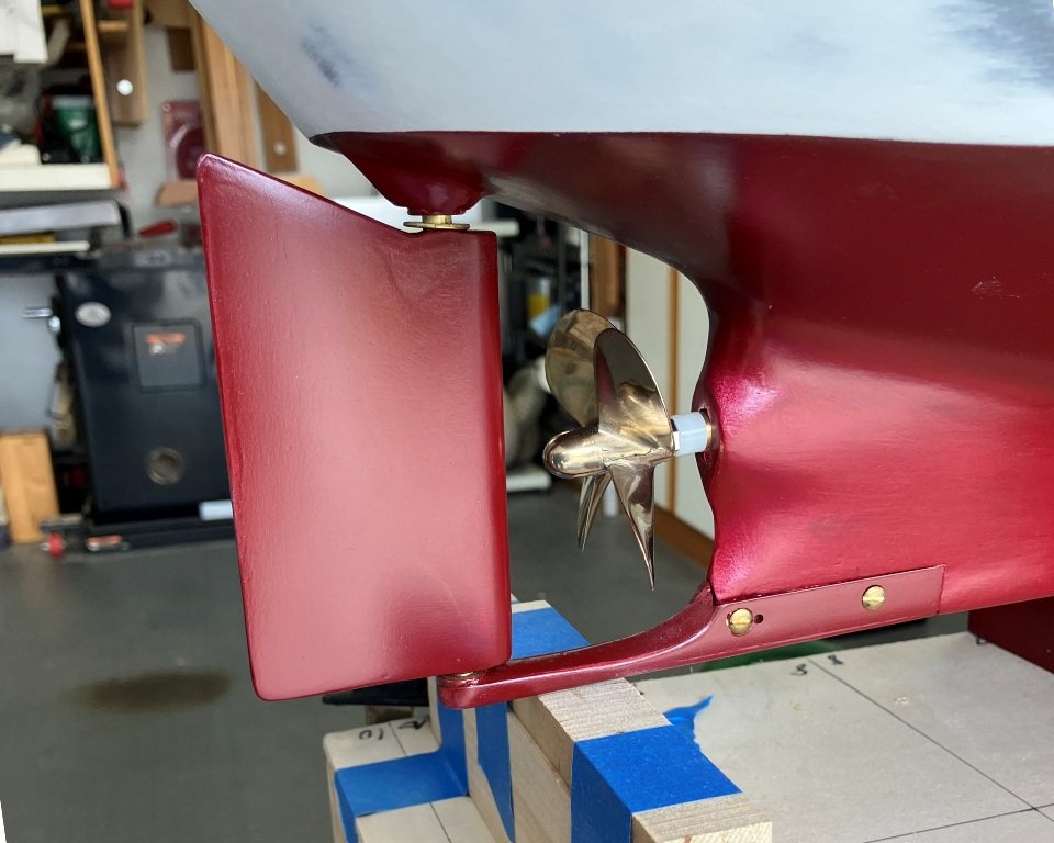
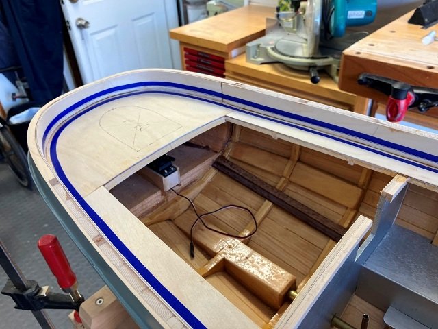
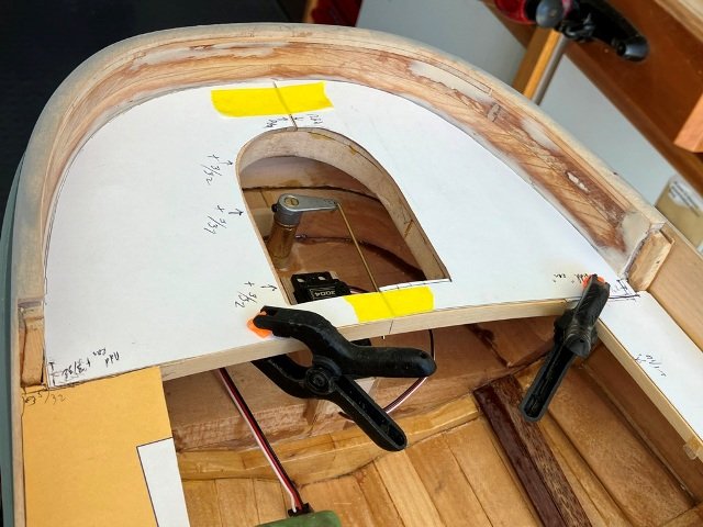
In preparation for completing the topsides planking, the stern bulwark was "beavered-up" from a laminated block of cedar and then bonded to the hull at deck level, using masking tape to hold it stationary while the glue cured. A set of deck beams were made up and glued atop the main deck clamps and to the additional raised foredeck pair of clamps. For the support provided while the planking continues, these beams span the full beam at their locations. Once the planking is completed, the fitting of carlins to the deck framing will trim out the middle portion of many of them. The rudder has been connected to the servo with a link to its tiller arm. I will finish this update with a (somewhat washed-out) photo taken this afternoon showing TWILIGHT awaiting further planking in the days to come. Until again, Craig

-
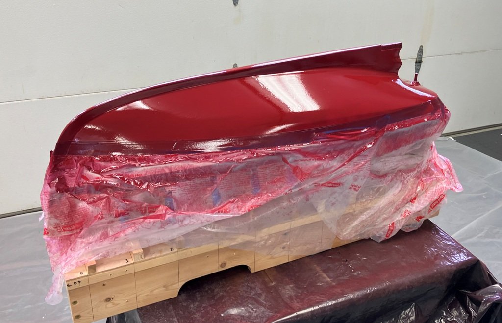
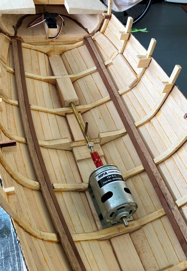
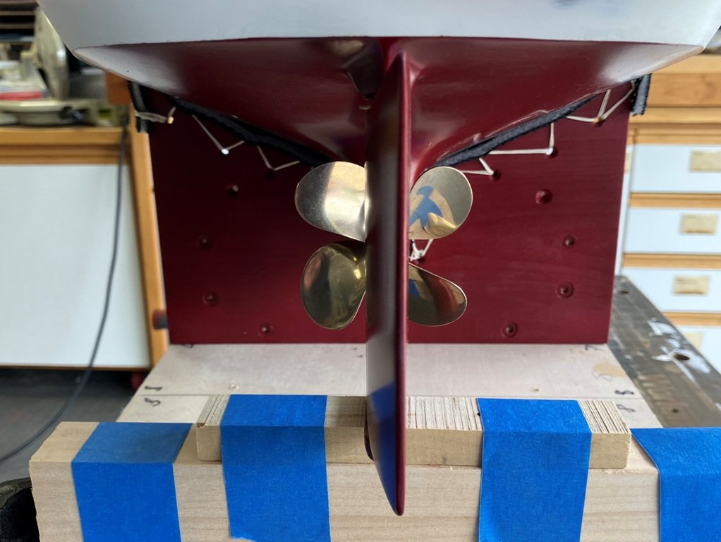
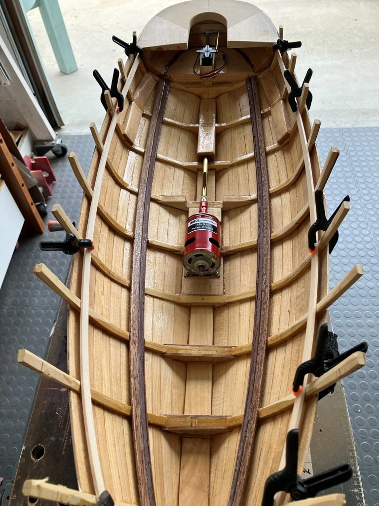
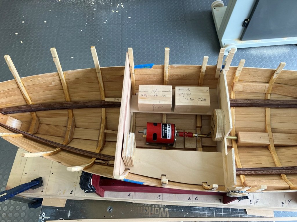
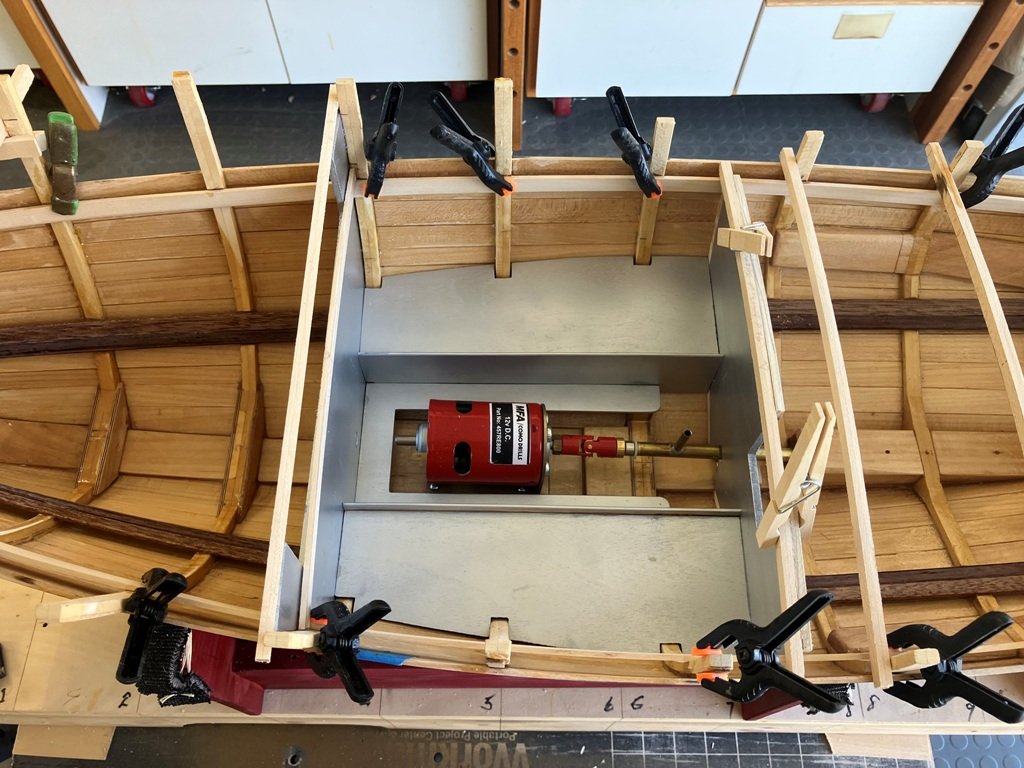
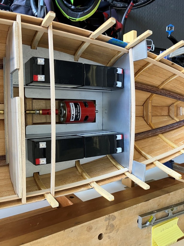
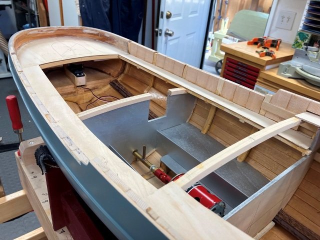
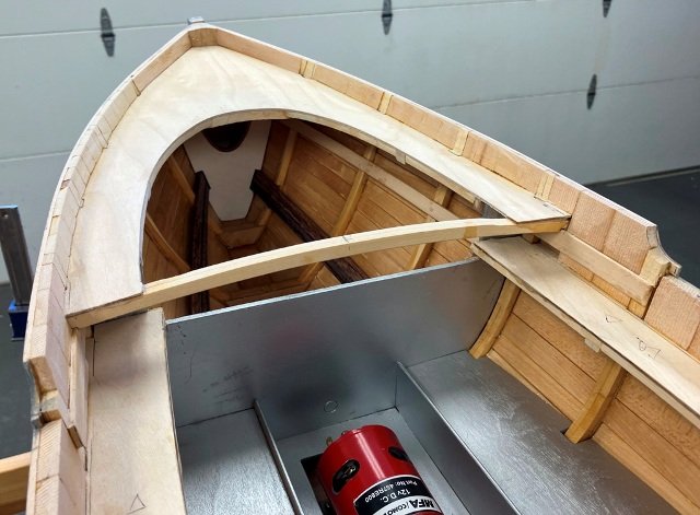
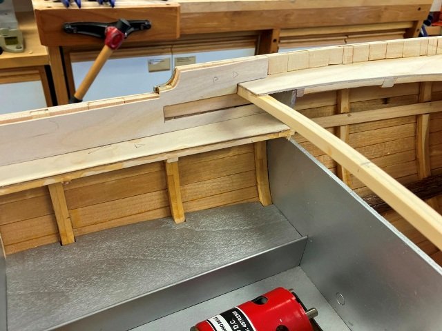
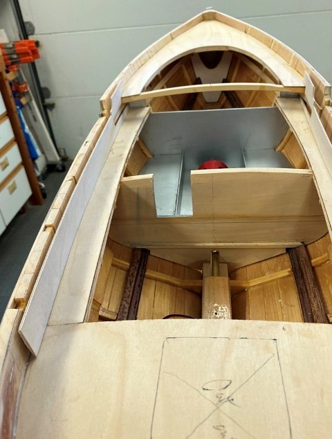
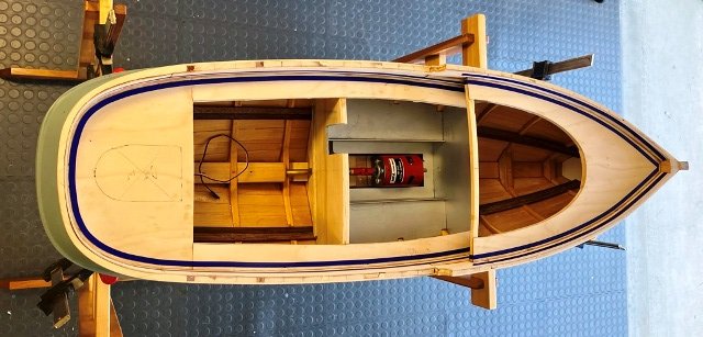
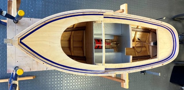
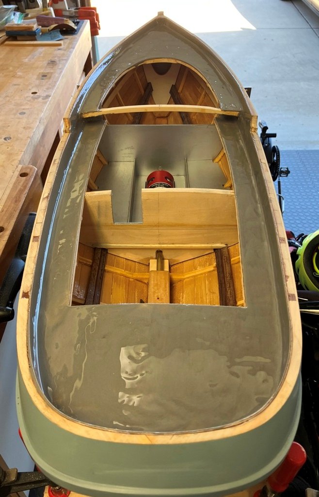
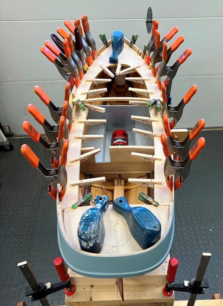
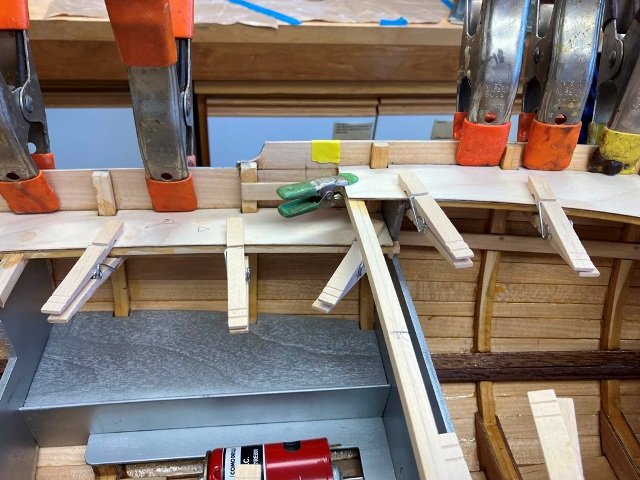
For the fun of it, I decided to do some initial priming with the bottom paint color (which darkened nicely when dry) - prior to making a cradle to hold the hull upright for the next series of steps. With hull rightside up, the cross spauls were cut away and the interior surface of the hull planking was scraped and lightly sanded, before it was sealed with a coat of clear epoxy. In addition, the motor location was finalized. This also permitted the fine tuning of the shaft length and a bit of shortening of the shaft tube to match. Ultimately, the after propeller thrust-bearing (white collar) position was adjusted about a 1/4" further forward than in the above photo. With the motor placement completed, beam shelves were fitted port and starboard and a couple of bulkheads were made up to define the motor space. I cut some dimensioned wooden blocks to check the sizes of the additional components which needed to be fit into the motor room*. Once it appeared that the lot of them could be accomodated, a bit of aluminum paint was applied. The mail man delivered a timely package about this time which contained the (4) 12vDC batteries plus other bits and it was gratifying to see that the battery support platforms located either side of the motor would work. * Aboard the diesel-electric tug I served on, the (4) Cat D399 diesel generators were mounted in the "Engine" room, while the 12' diameter, 440V electric motor was mounted in the "Motor" room. Seems logical, even for the USN. (More to follow)