HOLIDAY DONATION DRIVE - SUPPORT MSW - DO YOUR PART TO KEEP THIS GREAT FORUM GOING! (Only 20 donations so far - C'mon guys!)
×


HakeZou
-
Posts
325 -
Joined
-
Last visited
Content Type
Profiles
Forums
Gallery
Events
Everything posted by HakeZou
-
Hi Keith, I've only been building model ships for a bit more than a year, so am definitely relying more on the instructions than you. Learning a lot from studying the photos on your logs, though! I had to look up what bootlining was, so it definitely wasn't on my mind. After going back to Frank Hurley's photos, I'm not convinced that the Endurance had a boot line, so I think I'll keep it as is. I haven't found clear decisive evidence one way or the other, though, so am happy to be proven wrong. Hi Gerry, thanks for coming along! In my non-model-building life, I'm a historian, so I'm trying to leave as many breadcrumbs as possible for those who want to do further research when they build this kit. As for the James Caird, this tutorial video and the three preceding it will give you a good idea of the base version of the lifeboats (though the one shown in the video has a transom and the James Caird did not). I think the conversion could work in much the same way that Harry McNish did back in 1916—that is, build up the sides of the hull from the rails almost to the top of the stempost and sternpost, then fashion a deck with one open hatch. The James Caird made that journey rigged as a ketch; since the base model doesn't include mast feet, you'd have to fashion those, too. In addition, the model kit doesn't include a rudder for the lifeboats, which you may want to add. There are a lot of photos of the James Caird and various replicas, so it should be pretty easy to find inspiration; I note that one of the replicas, the Alexandra Shackleton, even has some schematics that are pretty easily available (for example)
-
Hi Keith, it took me awhile, but I found the same thing on the plans and in the photos. It looks like the skids for the forward lifeboats were mounted under the walkways that went from the bridge to the quarterdeck. This was the clearest photo I could find; and this photo shows them from a slightly different angle, with a clearer view of the cradles on which the boats sat. As for the dog huts, perusing the photos, it looks like they were built during the stop in Buenos Aires, before departing for South Georgia Island. Lansing confirms that the dogs only joined the ship during the stop in Buenos Aires (p. 26), but I didn't see a reference to building the huts there. As for my Endurance, some forward progress this week and some frustrations. The hull is painted and I'm working on the rails and trim. At the moment, the only rails installed are on the aftdeck, the after bulkhead of the cabins, and on one side below the portholes in the cabins. I had attached a few other pieces along the maindeck, but they looked terrible and weren't sitting right. So, I pulled them off and am remaking the pieces. To help them sit better, I've jumped ahead a bit and installed the pieces (M10 in the plans) that sit between the rails (K3) and the rubrails (L3). Since the M10 pieces abut both the rails above and rubrails below, I'm not quite sure why OcCre calls for putting them in so much later. By installing them now, I'll have a wider surface on which to attach the rails and can better ensure consistent spacing of the rubrails. Sorry for the mess in the background, but a quick photo of my current progress. Next steps: 9 more rail pieces to finish the K steps. Then, the rubrails and some trim pieces (the L steps). After that, the hull will be complete!

-
Hi Keith! I was wondering if you might be leaving the wood unpainted. I've been admiring your work on your Terror, which promises great things for how your unpainted Endurance will look! I can't say I know a lot about antifouling paint, though I've been researching it a bit while preparing for and working on this kit. My understanding is that, in England in 1912, copper antifouling was the most common option, but maybe lead was popular, too? This has been a hard topic to research, so there's a lot here that I don't know. Hi Johnny! Your experienced eye noticed something I hadn't in those photos. In terms of the lifeboats, I have been more struck by whether they were carried inboard or outboard. It seems as though the forward lifeboats were carried inboard until sometime in or near the Weddell Sea, at which point they were turned outward. The aft lifeboats seem to have always been carried outboard, presumably since the dog kennels made it impossible to bring them in. I'm strongly considering turning the forward lifeboats inboard, but have a long time before I need to make a firm decision. Your advice on the lifeboats is well taken; this will take more study on my end to figure out if I have the wherewithal for those modifications, though I really like the idea of including oars and unstepped masts. As for the railings, I hope you'll share your work on those in a buildlog! What you describe is well beyond my skill set right now, but I'd love to see how your approach turns out!
-
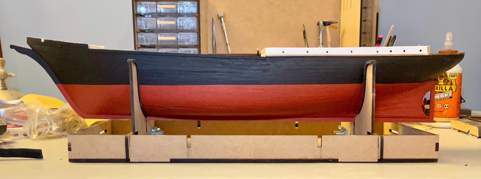
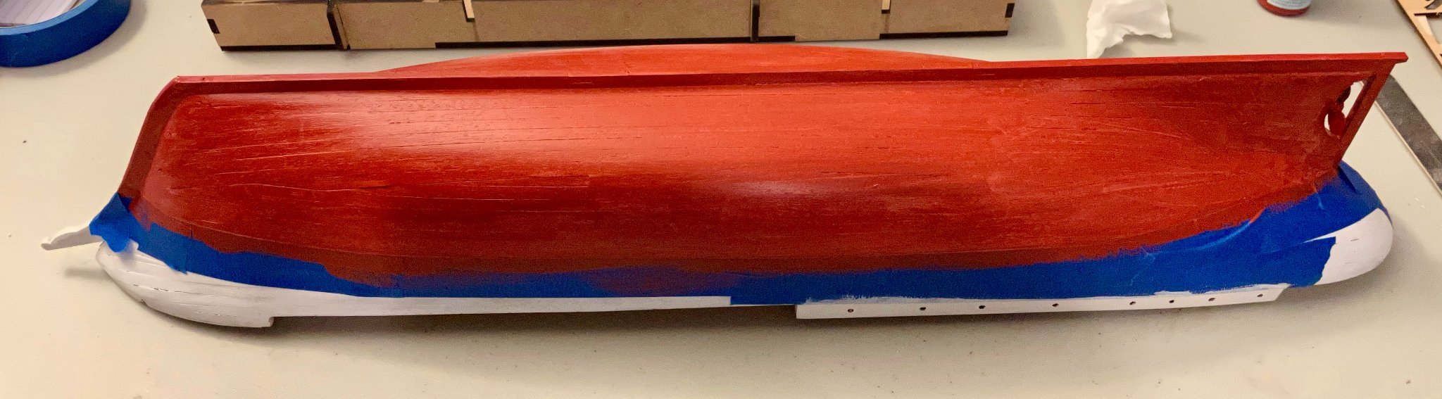
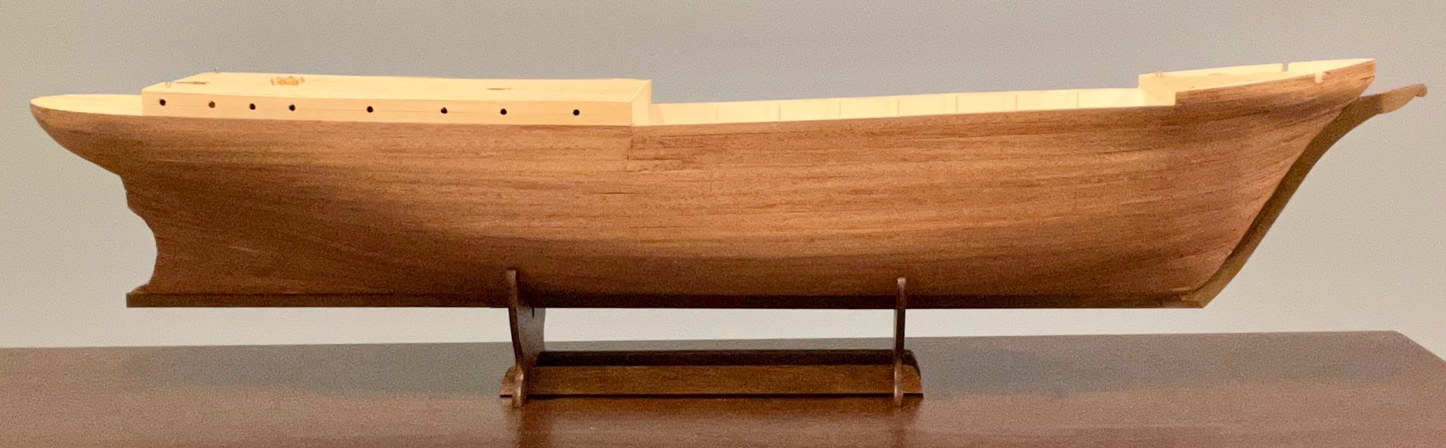
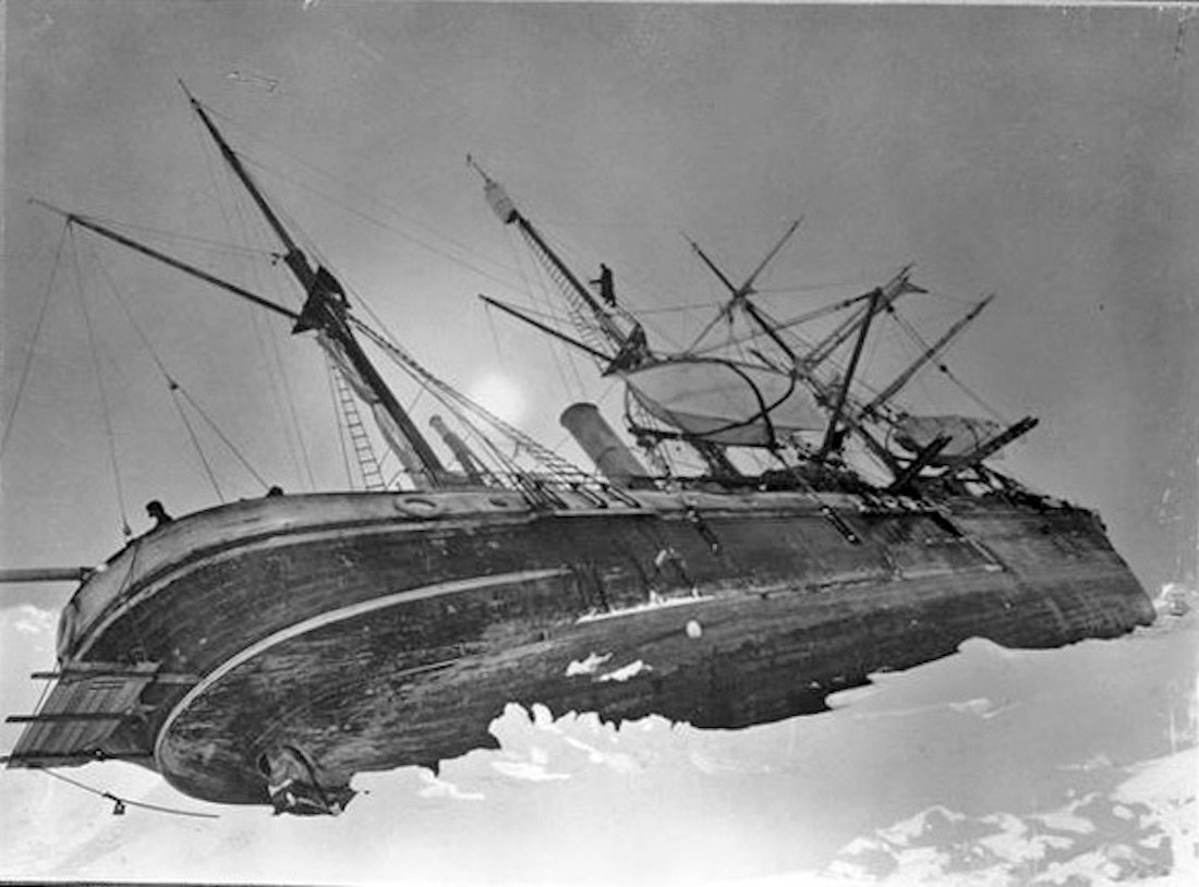
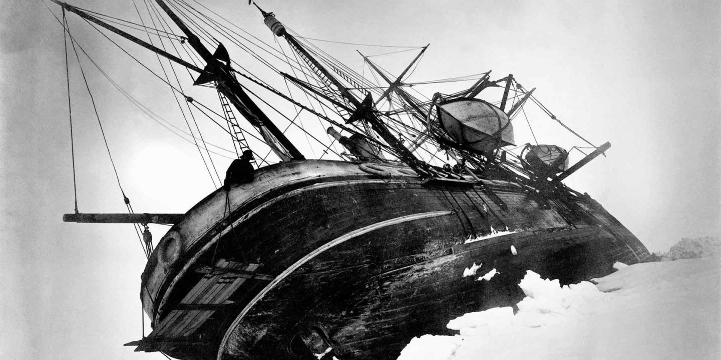
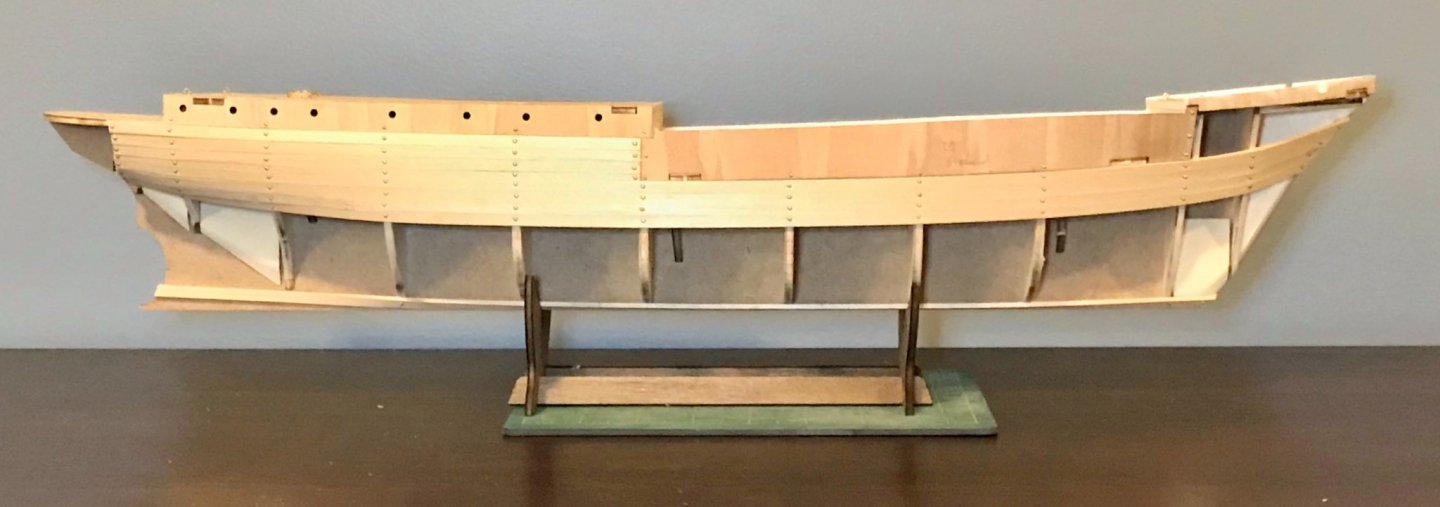
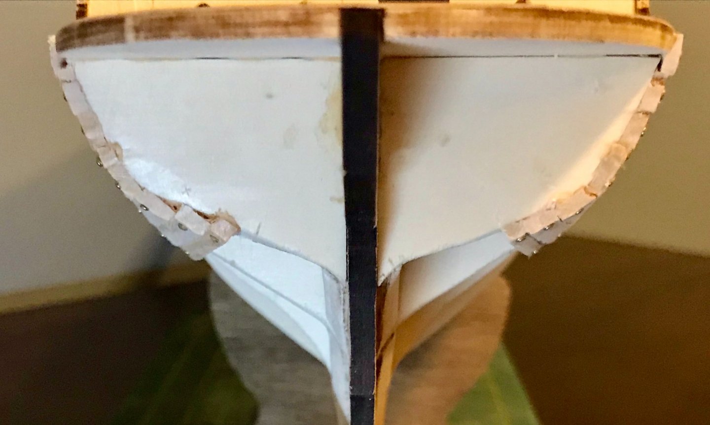
After sanding off the excess wood filler and applying primer this morning, I've just put on the first coat of paint below the waterline! This seems like a good moment to offer my thoughts on paint selection (note that OcCre offers a very handy color chart with recommended paints for all of their kits). First, the documentary evidence. The ship was built at Framnaes Mekaniske Werkstad, a shipyard in Sandefjord, Norway. Originally named Polaris, it was launched with an all-white paint job. It still had this paint job when Shackleton acquired the ship, as can be seen in a couple photos on Getty Images (Shackleton waving from the gangplank, Endurance leaves the docks in London). At some point, Shackleton had her repainted a "sleek black" (as it's described in Lansing's book). This is, of course, the famous paint job we all know and love. That paint job is confirmed, for example, in one of Frank Hurley's color photos of the ship. So, the top sides are easy. Below the waterline, a decision is needed for the antifouling paint. A quick Google search will show that some commercially available models have green paint, some a bright red, some a reddish brown, some bare wood, and some black. OcCre's recommended paint job is all black, both above and below the waterline. But that isn't supported by the documentary evidence. There's a photo on Getty Images that shows the Endurance in drydock at the Millwall Docks in London. She still has the white paint topsides, even though the name on the back has been changed, and she appears to have "white stuff" for antifouling below the waterline. Two of Frank Hurley's photos show that the "white stuff" must have been replaced when she was painted black. Unfortunately, they're black and white, so it's hard to confirm the color, though it's clearly not black or white. However, the expedition's artist, George Marston, gives us a little bit more of a clue, though the paints on the hull clearly appear lighter in his painting than they were in real life. All of which brings me to my decision. Drawing particularly on that painting by Marston, I've opted to use red ochre paint to simulate the original antifouling paint, which I'm assuming was "brown stuff."

-
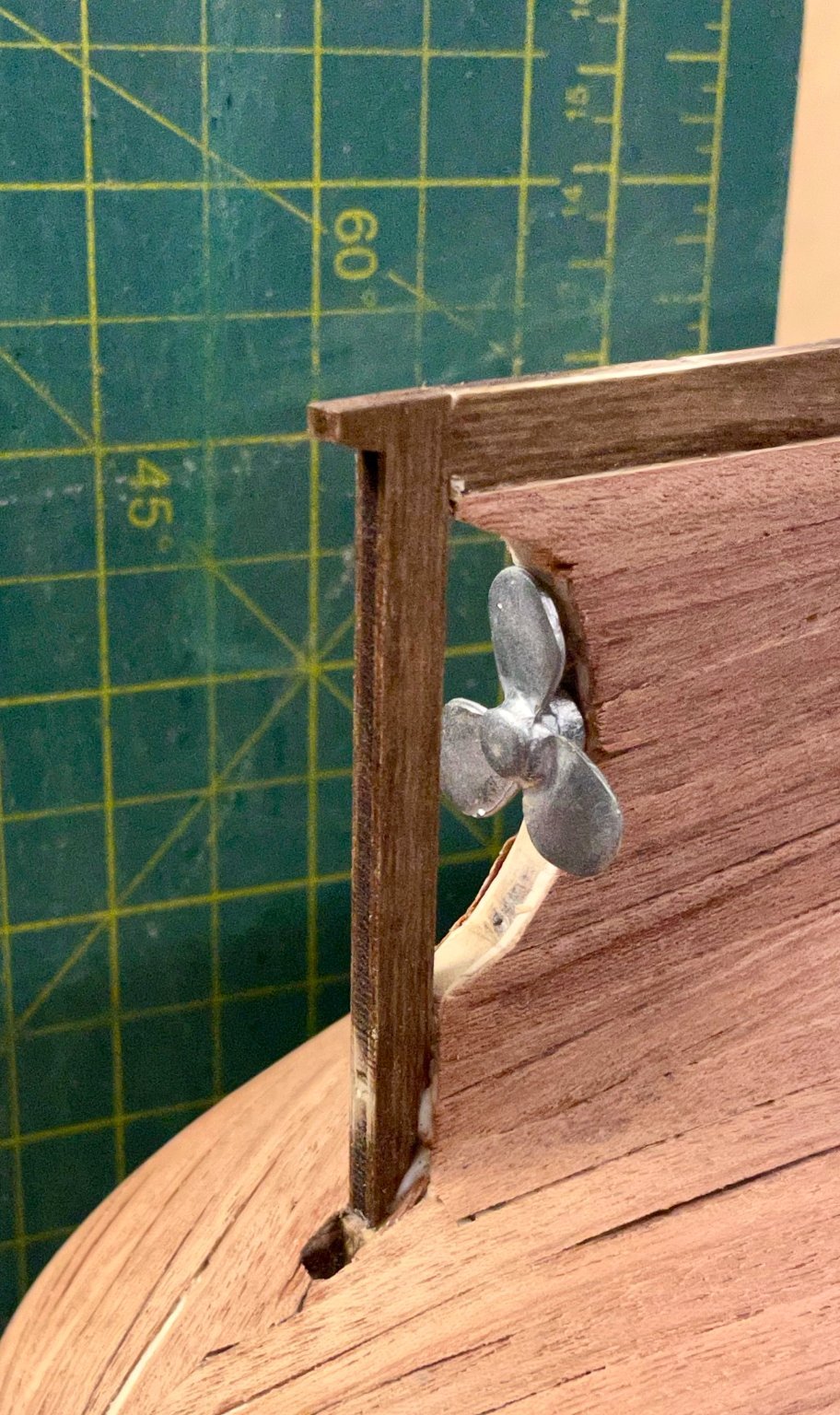
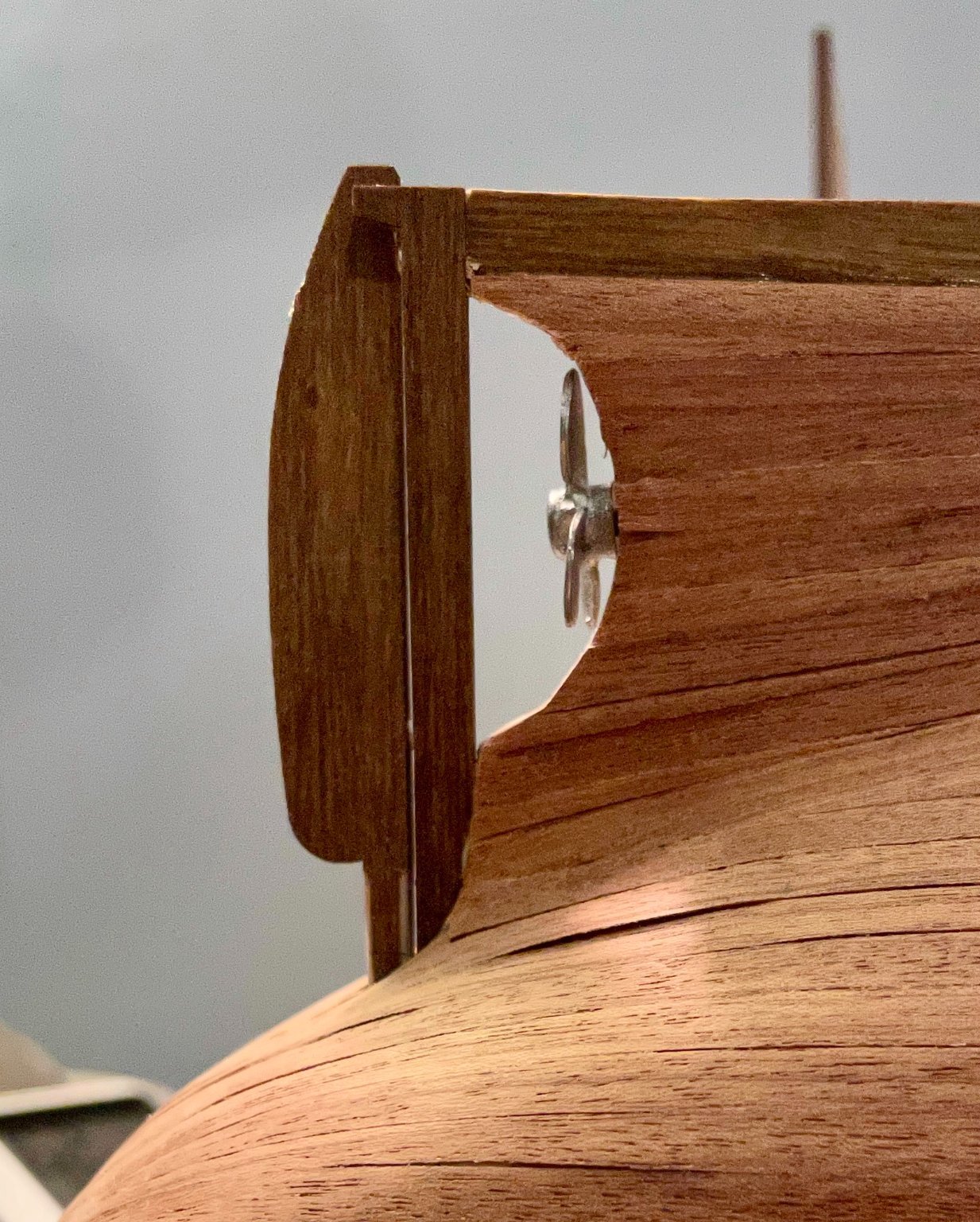
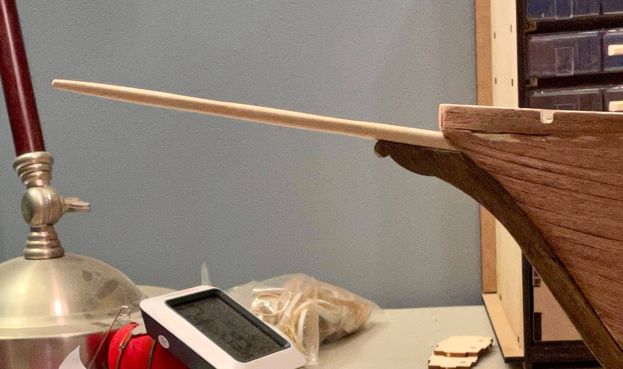
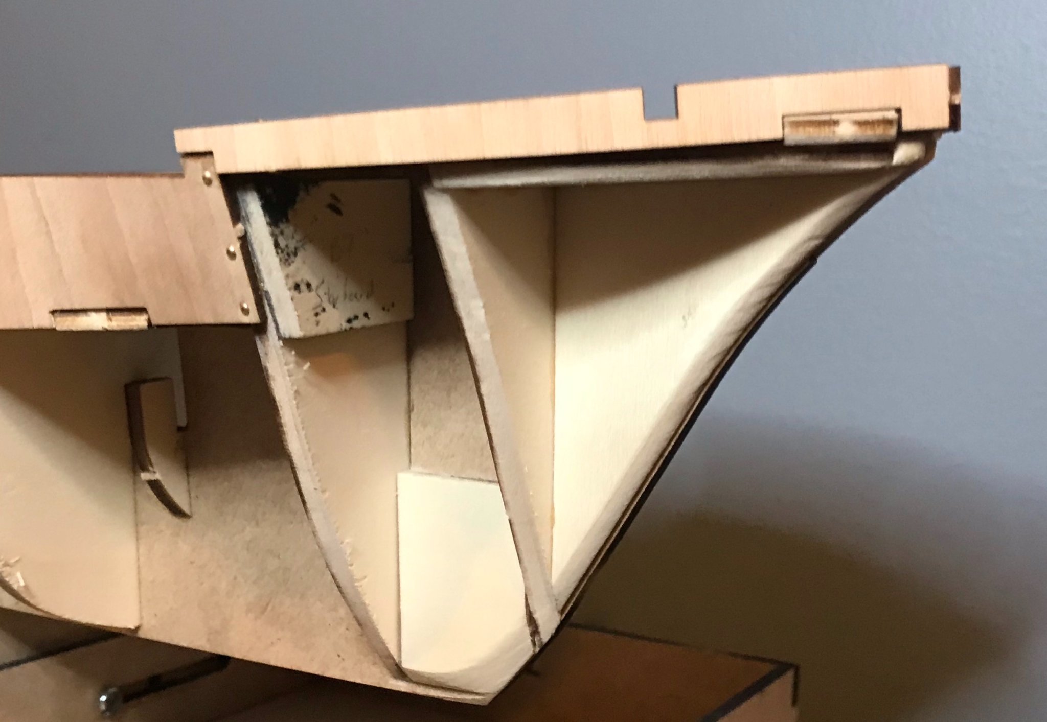
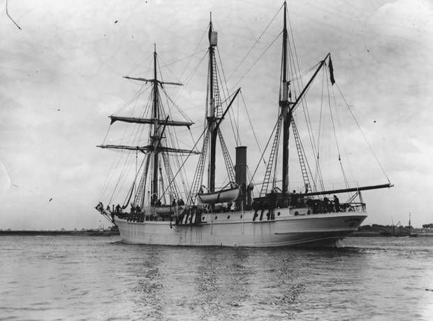
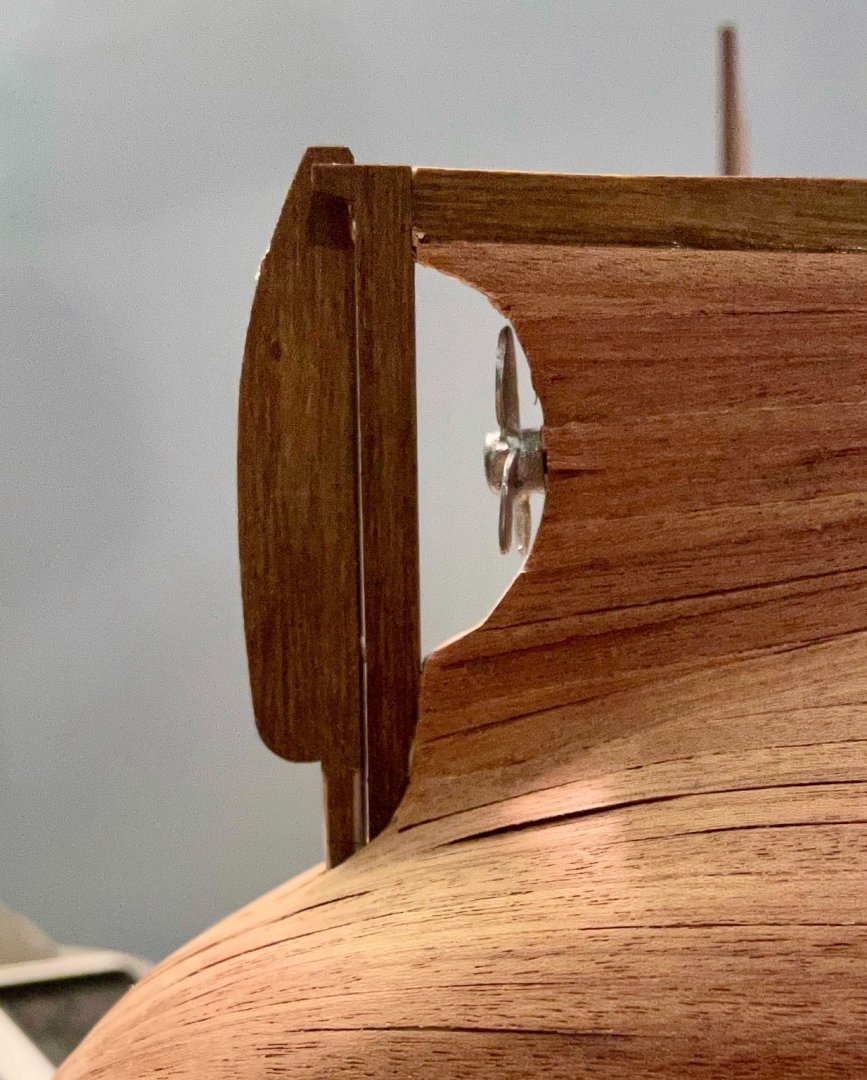
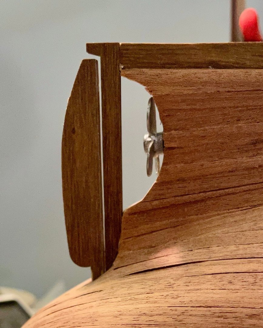
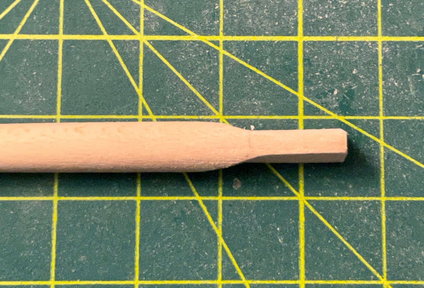
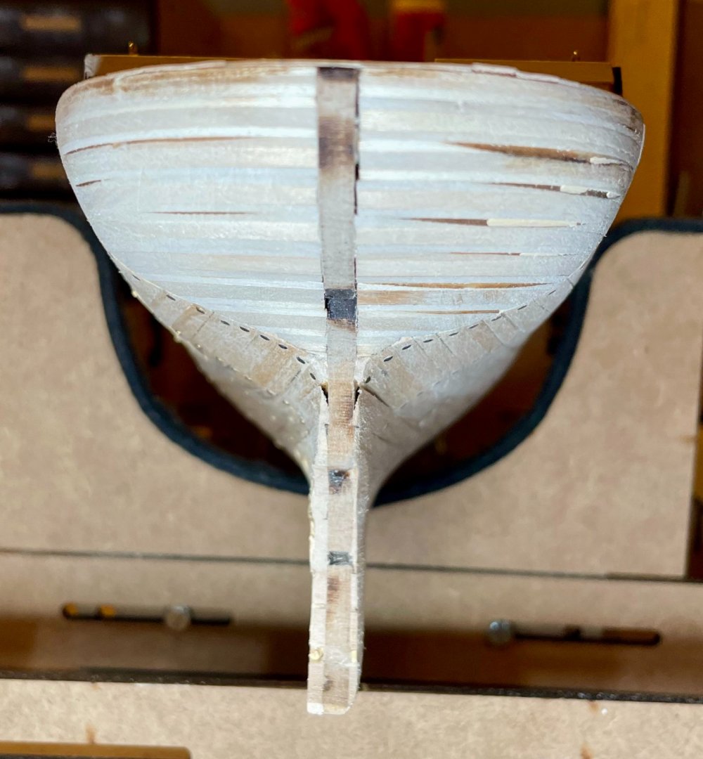
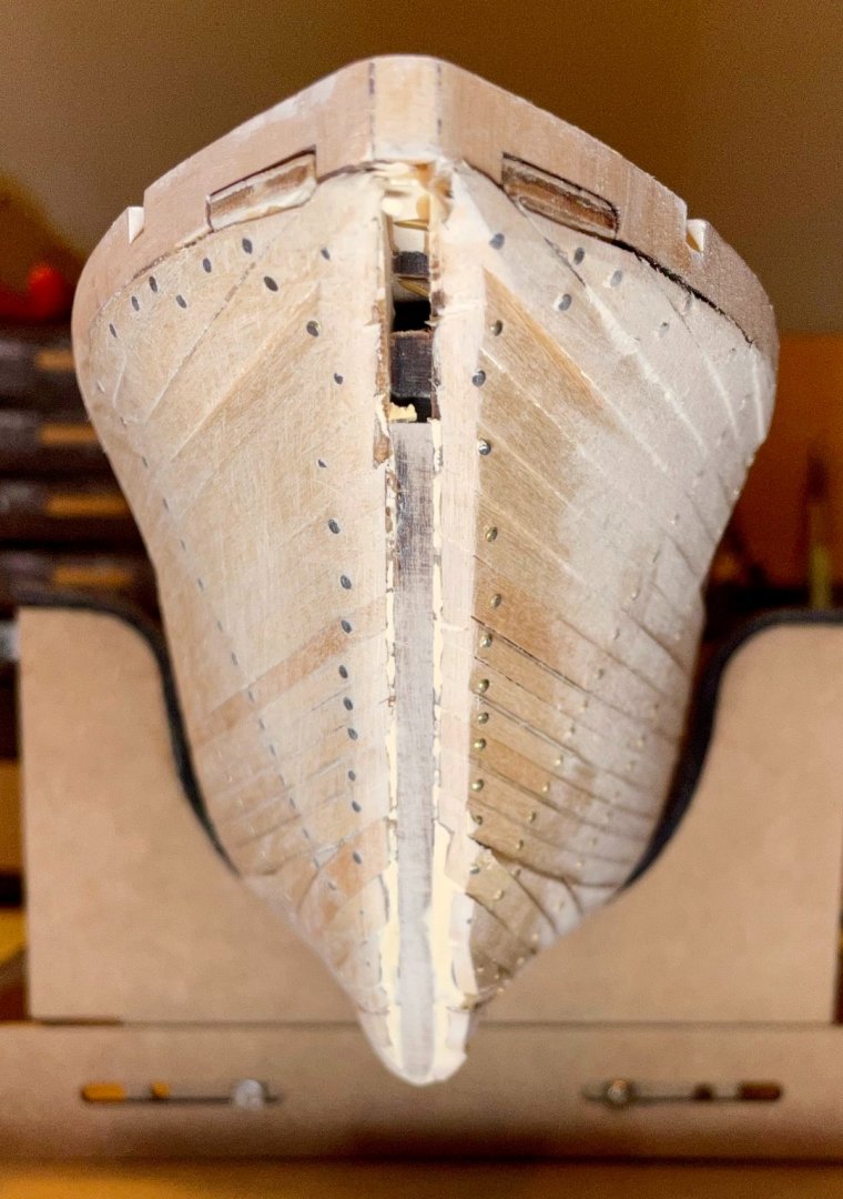
I took a little time this morning to do some of the small tasks that I wanted to get done before painting the hull. First, I sanded down the after bit of the keel and installed the sternpost. Nothing too exciting here. But once the keel had been sanded back, the top curve of the sternpost perfectly fit the curve of the counterstern. While the glue was drying, I pulled out the propellor, to make sure it would go in easily. Unfortunately, not so much. In my very first post, you can see that there's a notch for the propellor that is pre-cut into the spine of the ship. Unfortunately, while planking the hull, that notch filled with glue and so there was no way to push the propellor in. I pulled the sternpost off, drilled out the hole for the propellor, installed it, and re-installed the sternpost. If you're building the Endurance, the instructions have you install the sternpost before the propellor; if you do it in that order, be sure to check the fit of the propellor before installing the sternpost. In my case, I will be painting the propellor the same color as the surrounding hull, so it's just as easy to install it first. (Sorry for that bit of wet glue in the photo!) Next, I checked the fit of the rudder. As I noted previously, the hole into which the rudder is inserted is smaller than the rudder. So, I started by rounding off the top stem of the rudder. Once that fit into the hole, I discovered that the stem was too long by about 6mm (see the first photo). After sanding the stem down, everything fit pretty well, except that I may have taken off slightly too much (see the second photo). I'll paint the rudder separately, since the two faces are so close to each other, so not installing it yet. Once I do install it, the only hardware called for is a pin that runs through the tap off the back end of the sternpost into the bottom of the rudder. One option for upgrading the kit would be to add some brass strips and rivets; this would give a more authentic look; there isn't enough space for a hinge pin, but there should be enough for the brass strips. I'm going to have to look through my supplies to see if I have enough on hand to do that upgrade. Finally, I have now shaped and dry fit the bowsprit. I wanted to be sure to do this before painting and adding the various bits of trim/rubrails/etc, so that I could check everything with the bowsprit in place. There's plenty of vertical space for the bowsprit, but I did have to take in the sides a bit. Next steps: use wood filler to cover up my indiscretions in the lining of the hull, then mark the waterline and start painting.


-
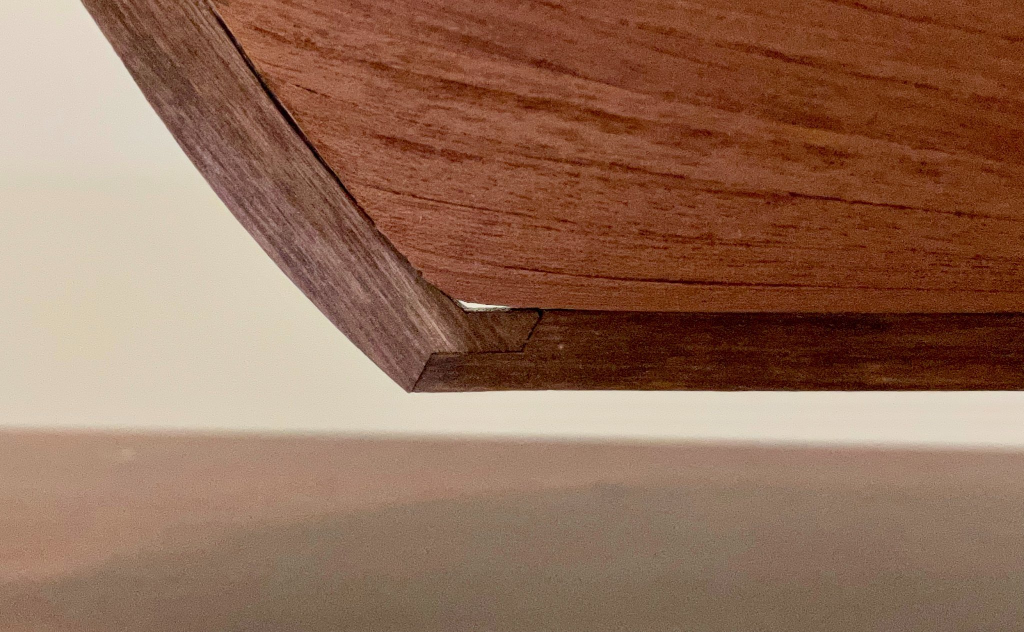
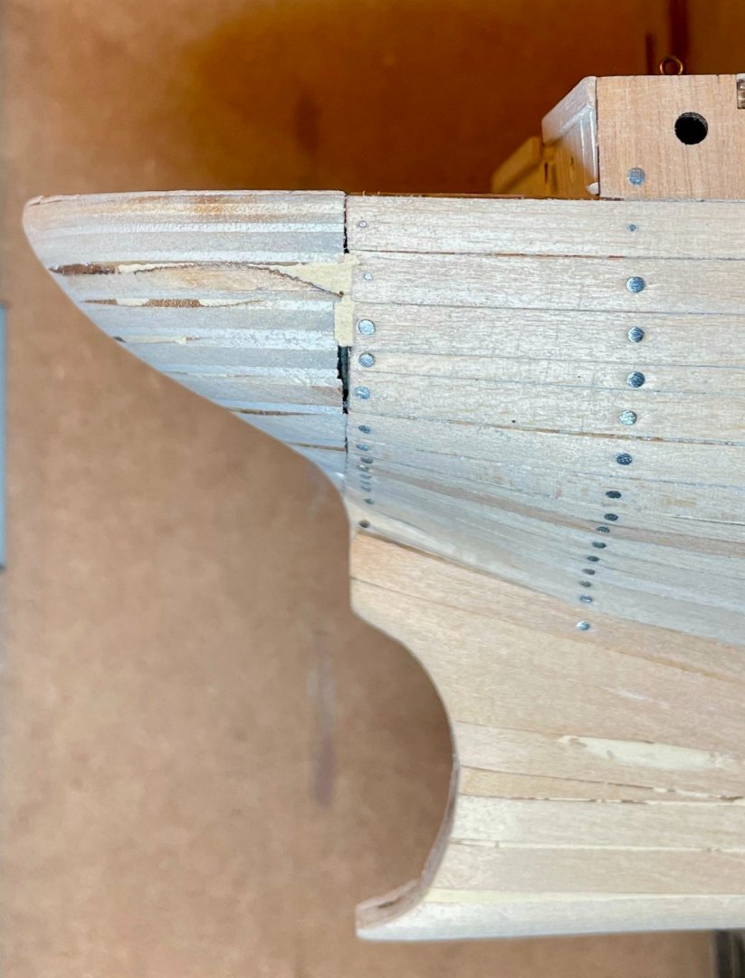
Hi everybody, thanks for the comments so far on the question I asked about the varnish! It's really helpful to have your perspectives as I keep learning. Tom, you ask a great question about whether it's worth putting on the second hull planking if it's going to be painted. This is only my second double-planked kit, so I certainly can't pretend to know much here. But for me, I find the second planking an opportunity to get a better, smoother base for painting. I'm not sure if there's actually a difference or if it's just a perception that comes from doing the additional work. For my specific version of the Endurance, it was definitely necessary, since I had nailed the first planking into place (as OcCre recommends). For this kit in general, if you choose to do a single planking, keep an eye on the tab/slot joints were the bulwarks attach to the decks; those will need a bit of attention if they aren't going to be covered up with a second planking. In the meantime, I've been working on sanding and smoothing the hull. As always at this process, it's such a pleasure to feel the transformation of the wood! (Linda Richman's catchphrase comes to mind, "It's like buttah!") There are some scattered imperfections in my work and gaps, so I'll need a bit of wood filler before painting, but overall, I'm pretty pleased with the hull. As you'll note in the photo above, I've also attached the stempost and keel (one half of the K steps, which also include attaching the rails). In doing this, I encountered two issues that others building the Endurance should watch for. The first issue, which is my fault, is a small gap where the stempost meets the keel (see the first photo). The gap was created while sanding the first planking. The MDF frame and the stempost/keel are all the same width, so I worked on sanding the planking down to nothing at the edge, to simulate a rabbet line. In doing so, I managed to round the angled corner of the MDF frame. I plan to carefully insert some wood filler and don't anticipate any further problem once the hull is painted. The other issue is that the keel is too long. You'll note in the photo that the sternpost should attach to the end of the keel, then run up to the curve of the counterstern. I'm not sure if this is a genuine fault in the kit or if this was caused when I was sanding the first planking of the deadwood. Given the amount of excess, I think it may be an error with the kit. If so, better that it's too long than too short! The remedy here will just be a bit of unanticipated sanding.

-
Yes, definitely a sigh of relief, Keith. The second planking is definitely needed for this kit. Without it, the plywood walls of the main cabin would have to be left bare. I've squeezed in a little time sanding now and am already feeling better about how things look at the stem. In the photo from my last post, you can see the raggedy edges there, which looked even worse in person. The counterstern is an interesting challenge for sanding and filing. As you work on your Endurance, keep an eye on the hole that houses the rudder. It's not wide enough for my flat file and so shallow that I can't get much movement with my square file. I've already cut the rudder from its plywood sheet so I can check the fit at this stage. It will be slow going to be able to fit the rudder in and requires frequent attention from the shop vac to clean it out! In watching the next few tutorial videos, I notice that OcCre applies the satin varnish before painting. I'm still new enough in this hobby that I don't understand why...nor do I adequately understand the difference between satin varnish and satin finish (which I thought were interchangeable terms). I'd love to hear some thoughts and advice on this from more experienced builders. I have some time before I'm ready for painting, but will need to make my decisions on that in the next few days.
-
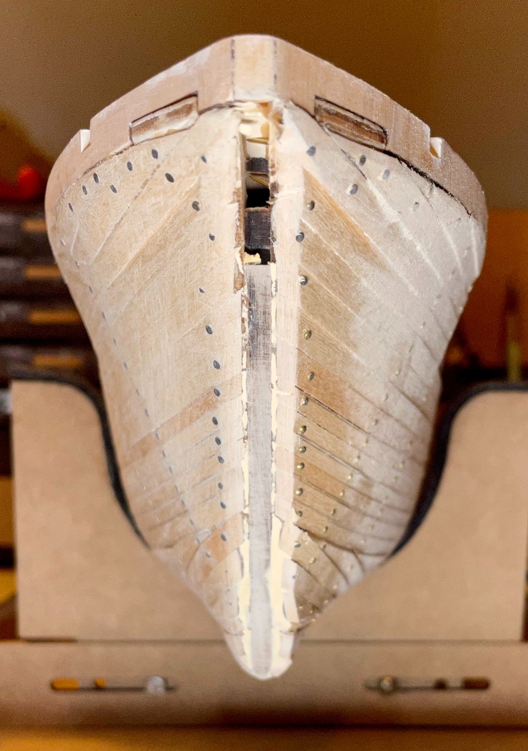
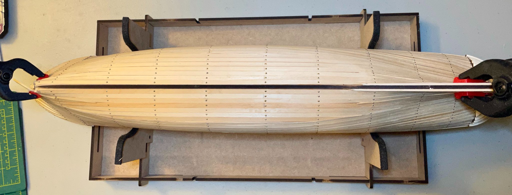
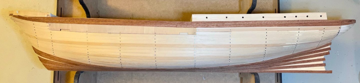
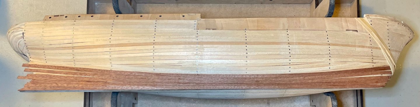
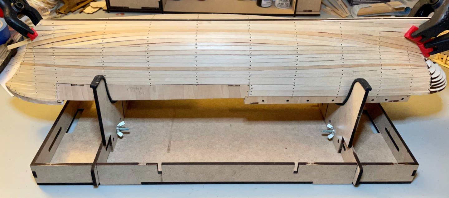
Yesterday afternoon, I placed the shutter planks on both sides. This morning, the birds woke me up absurdly early, so I decided to add the last of the stealers. But now the hull lining is completely on! There's a lot of clean-up left to do, but it feels great to have finished this step!
-
Hi Keith, I just discovered your log this evening! Looks like we're in a pretty similar spot at the moment, working out the challenges of the second planking. Our solutions for the counterstern planking are different and yours is more historically accurate than mine. (Here's a photo of the Endurance's stern in drydock, just in case you haven't come across it yet). I'm particularly impressed at how well you got the planks to follow the curves there! I initially tried a similar approach but couldn't get the planks to lie flat enough. Keep up the great work! I'll be following with keen interest.
-
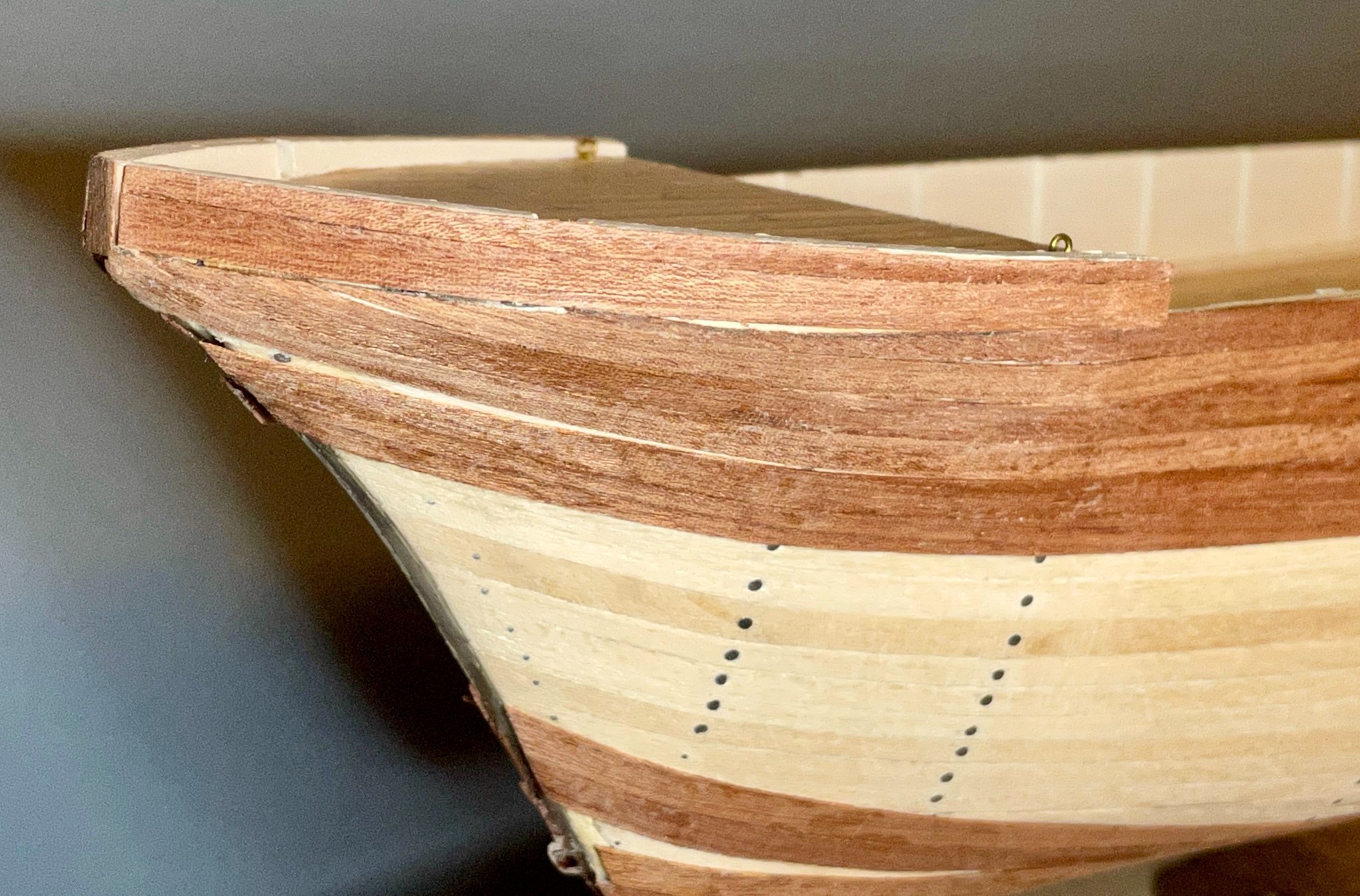
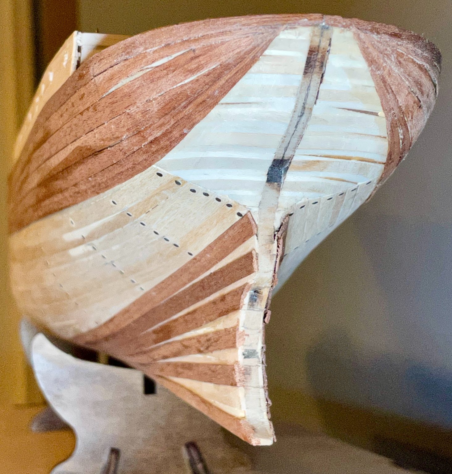
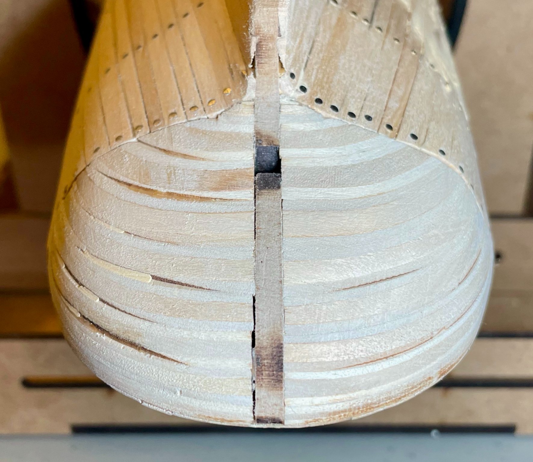
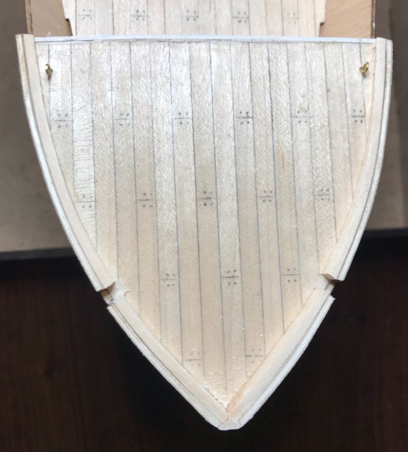
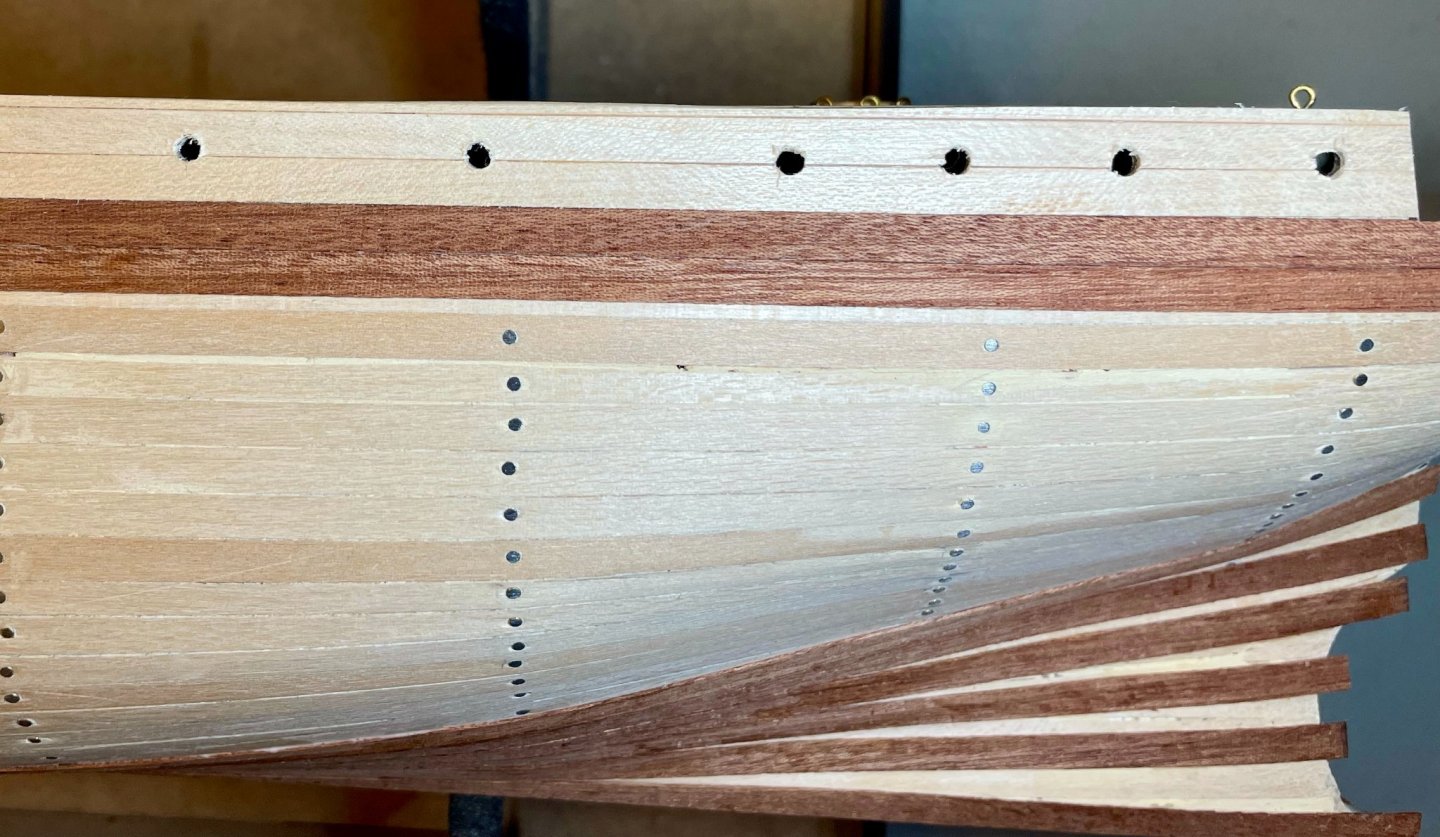
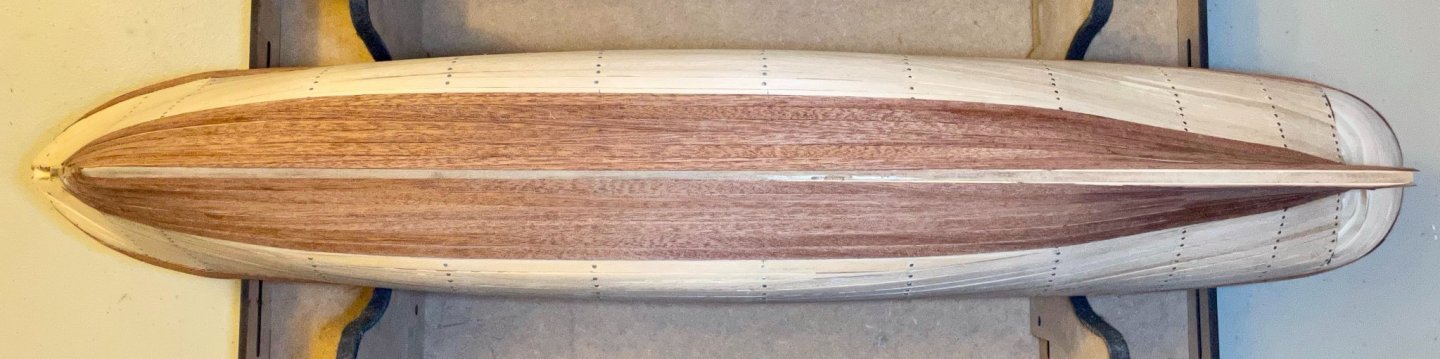
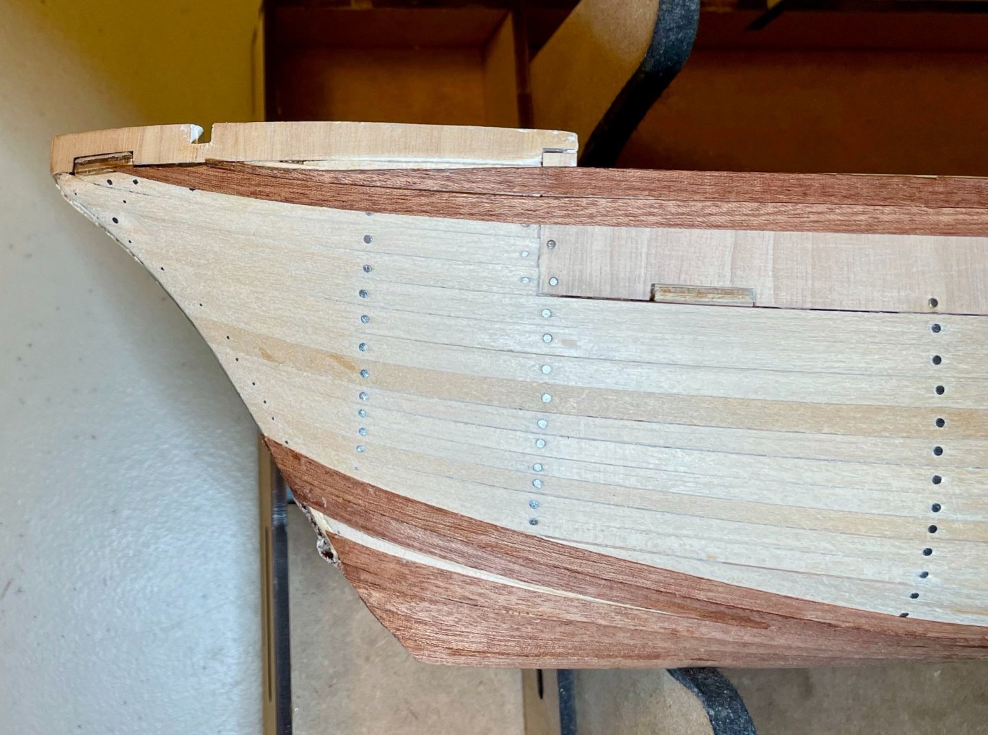
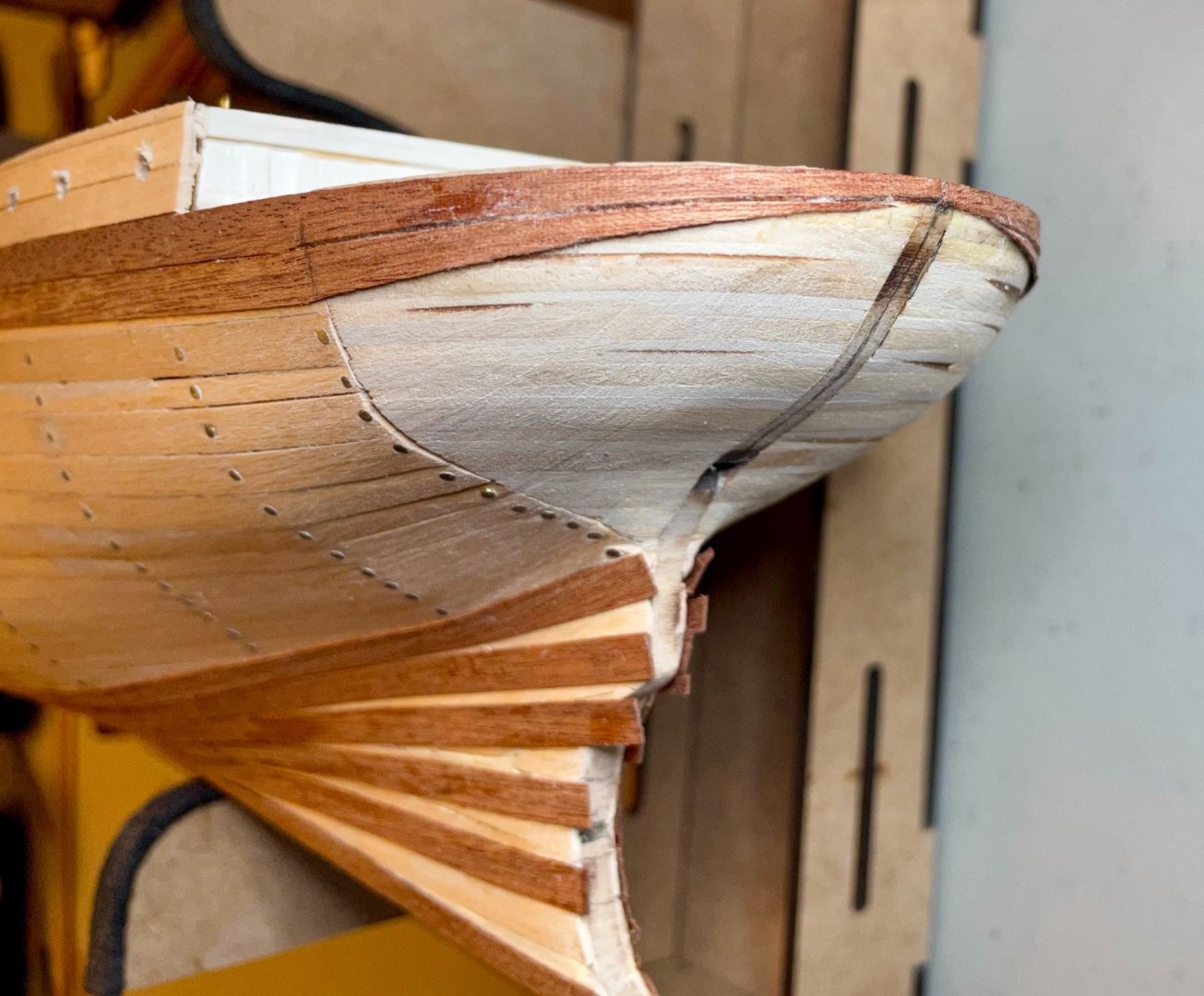
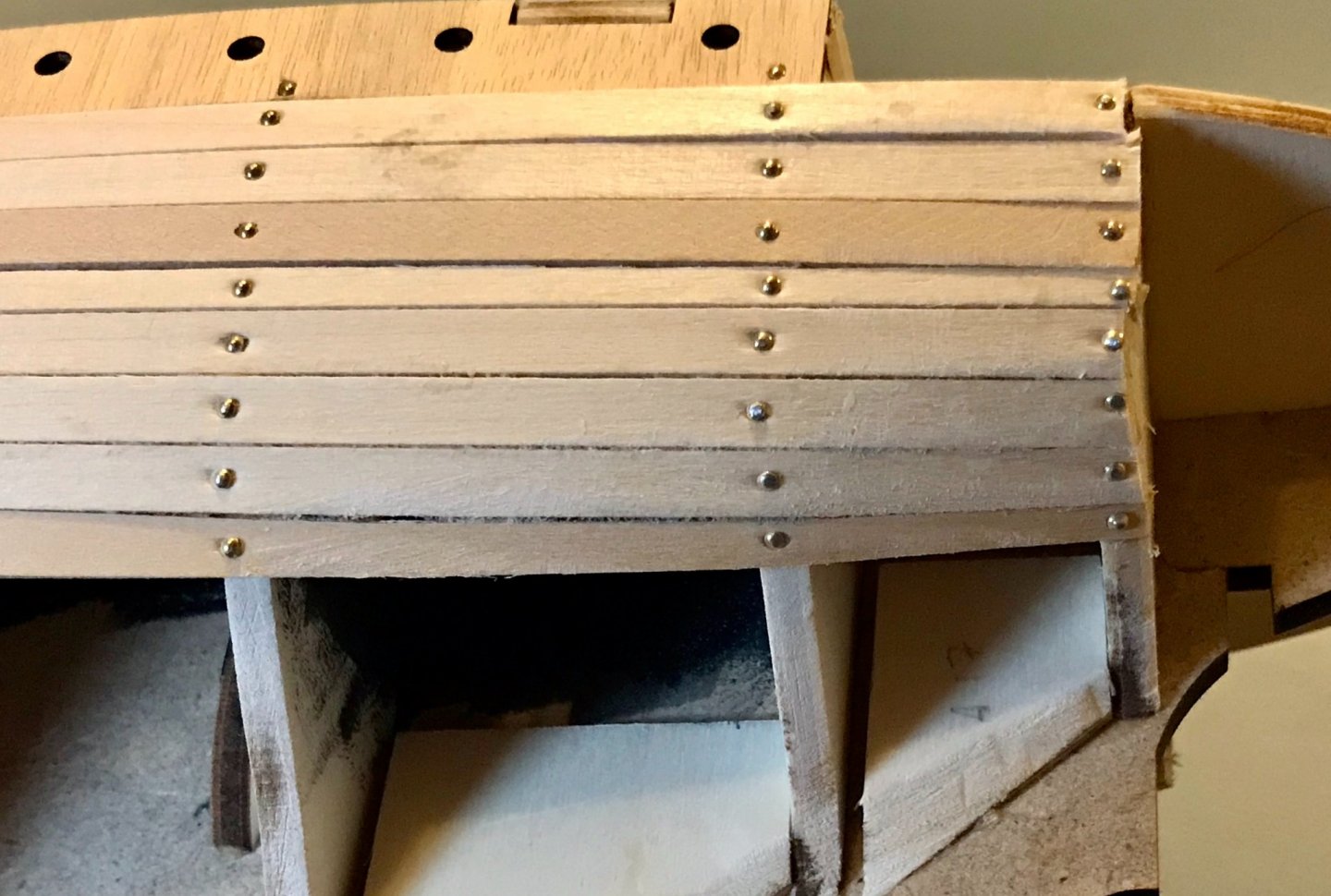
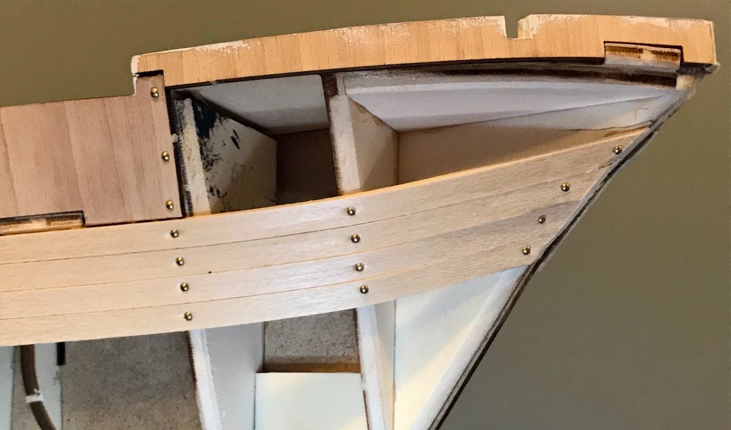
Thanks, Bob! Nice to have you along for another voyage. I've put in a bit more work on the Endurance this week, adding four more strakes to each side and lining the rail around the forecastle. I also still need a stealer at the bow between the 4th and 5th strakes, and I need to cut out the anchor channels in the sapelli lining. The detail shots show that I will definitely need some woodfiller before painting. My hull planking skills are improving, though I still need more practice. I also just bought a 6-inch razor saw, which is helping me cut straighter lines on the longer tapers. In this shot of the counterstern, note that there are no gaps between strakes 4-5 and 5-6! (Ugh...that excess dried glue on the starboard side looks terrible here! It should come off once I start sanding...) Next steps: More slow and steady progress with the planking.


-
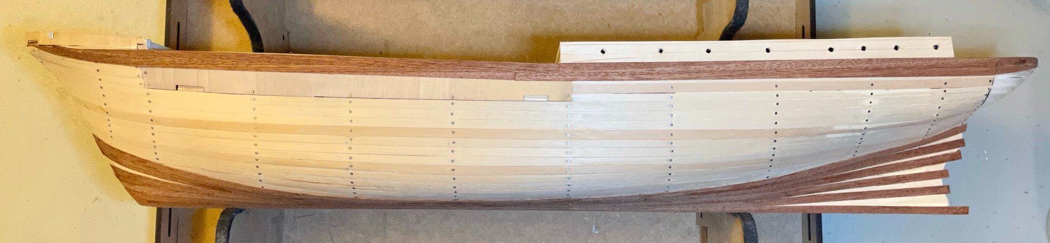
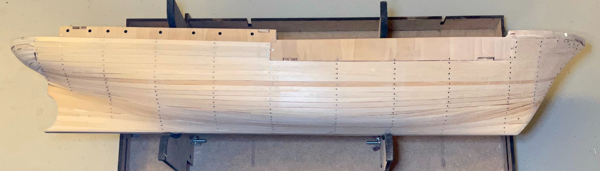
It's been a very busy month since my last update, so not a whole lot of progress. But I've been able to get some time in on the Endurance over the last couple of days. I'm still working on the second layer of the hull and still facing some frustrations. However, I think things are starting to work out. My main goals lately have been to 1) get the port side caught up to the starboard side and 2) install the shear strake. As far as the port side, I'm almost caught up. I've installed six planks from the garboard up to the bilge curve. Once I install the stealers, both sides will match again. The shear strake is an interesting problem, since I just can't find a way to run that strake from the stempost to the sternpost. I have, however, installed the top two strakes on both sides, in addition to planking the sides of the main cabin. At this point on the hull, the strakes are significantly longer than the planks, so I've used two planks for each strake, which abut each other roughly amidships. At the forward end, the curves of the hull mean that the top strake curves upward and ends at the channel cut out for the anchor cables. The second strake goes a little further forward. I think it'll be the fourth strake that actually reaches all the way to the stempost. The curves of the counterstern cause a similar problem, too. The shear strakes meet neatly at the stern, though the second strakes curve in such a way that they don't actually abut. Finally, a quick note on the lining of the cabin, for those who are also building the kit. I did the lining per the instructions, but think it could be done better. The lining consists of 5mm-wide sycamore planks, but the cabin is about 11 or 12mm tall. The instructions call for two full-width planks and one trimmed very narrow. I suspect that this could probably be done a little more neatly by trimming the planks to 4mm wide. Next steps: I'll add in the stealers below the bilge curve, then continue working my way down from the top.
-
A quick update after some recent frustrations. I finished sanding the base layer of the hull and have started installing the second layer. First, the good news. The sapelli wood used for this step is the best example of that species I've worked with. Admittedly, I still have pretty limited experience, but I'm used to sapelli being very fragile and brittle. In this case, it's supple, flexible, and very easy to work with! Now to the frustrations. My initial plan was to follow the instructions (as illustrated in this video), but I just wasn't pleased with how the shear strake was laying. I couldn't get the lines quite right, it needed edge setting, and it wasn't laying flat. After installing and removing a couple planks, I threw my hands up and decided to start from the garboard strake instead. Here, things are going much smoother! I'm having a little trouble getting the planks to stay down at the stem, so that's why you see the rubber bands in this photo. I've applied a little bit of extra touch-up glue there and so will leave the rubber bands on overnight. By the morning, things should be fine there. 5 planks and 2 stealers on. I'll do 1 more plank from the bottom, then will need to go back to the shear strake and work my way down.
-
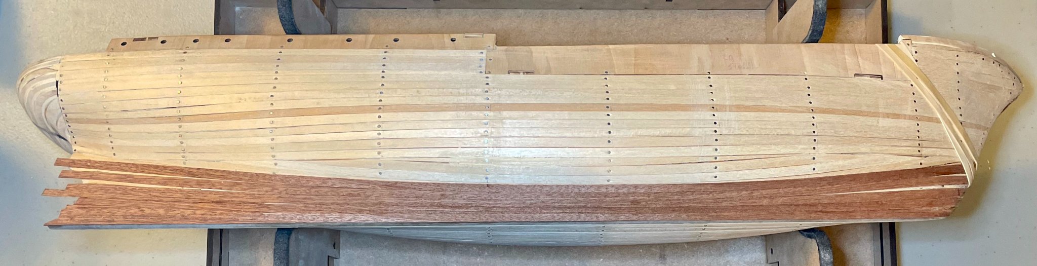
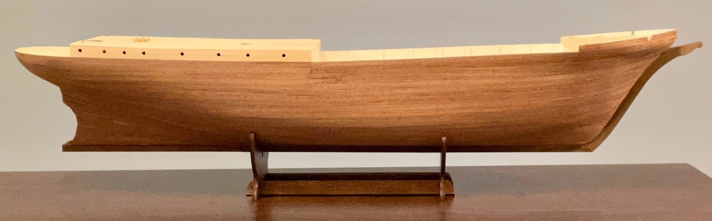
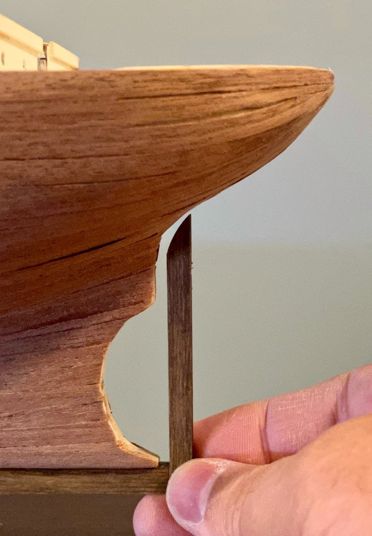
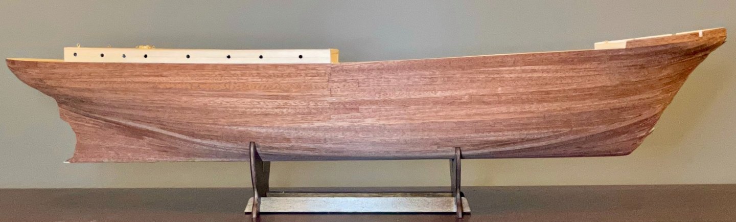
The sawdust has been flying here and I've lost count of how many sanding sticks I've worn bare. But I'm about halfway done sanding the base layer of the hull. Per the recommendations in the instructions, I started with the stacked blocks of the counter stern, then worked my way forward. Looking back at the mistake I described in the post about the counter stern, I'm pleased to say that wood filler did the trick! Two photos here to show the rounding, first an overhead shot with the ship inverted and then a profile shot from the starboard side. The second shot also shows the rounding of the space where the propellor will eventually be installed; this was a tricky spot, but I used a combination of a round file, a wider half-round file, a screwdriver handle wrapped in sandpaper, and my finger wrapped in sandpaper. The space around the H9 blocks (the two smallest in the counter stern, which are sanded away to almost nothing) was also pretty challenging. At this point, the multidimensional curves of the counter stern meet the lower curve of the stern and the deadwood; I found that wrapping my fingers in sandpaper was the best solution here, since they could follow all of those lines as they came together. I've worked my way to the stem on the starboard side. No surprise that the two really challenging portions to sand were the stem and stern. But you can see how those have turned out in the next two photos. One of my goals in this kit is to make a better hull than in any of my previous kits. Now that I understand the principles and practices of rabbet lines, I feel like I have a good shot of that. With the second planking in mind, I'm these planks down from 2mm to almost nothing at the edges where the stempost, keel, and sternpost will be installed. You will hopefully be able to notice a pretty significant difference between the port and starboard sides, even though I've already done some preliminary sanding on the port side. Finally, a shot of the starboard broadside. Next step is to sand down the portside to match, then to start fairing the hull.


-
Yes, exactly, Johnny. My carelessness came because I went pair-by-pair. But I think it would be better to dry-fit all 16 pieces first, since the alignment of the corners will be more visible. And it's definitely important to mark both left/right and top/bottom. (Although I kept the pieces consistently on each side, I didn't think to mark top/bottom, since I didn't realize that the symmetry of those two blocks was only near-symmetry.) Sanding is coming along slowly and steadily. More photos to come soon(ish).
-
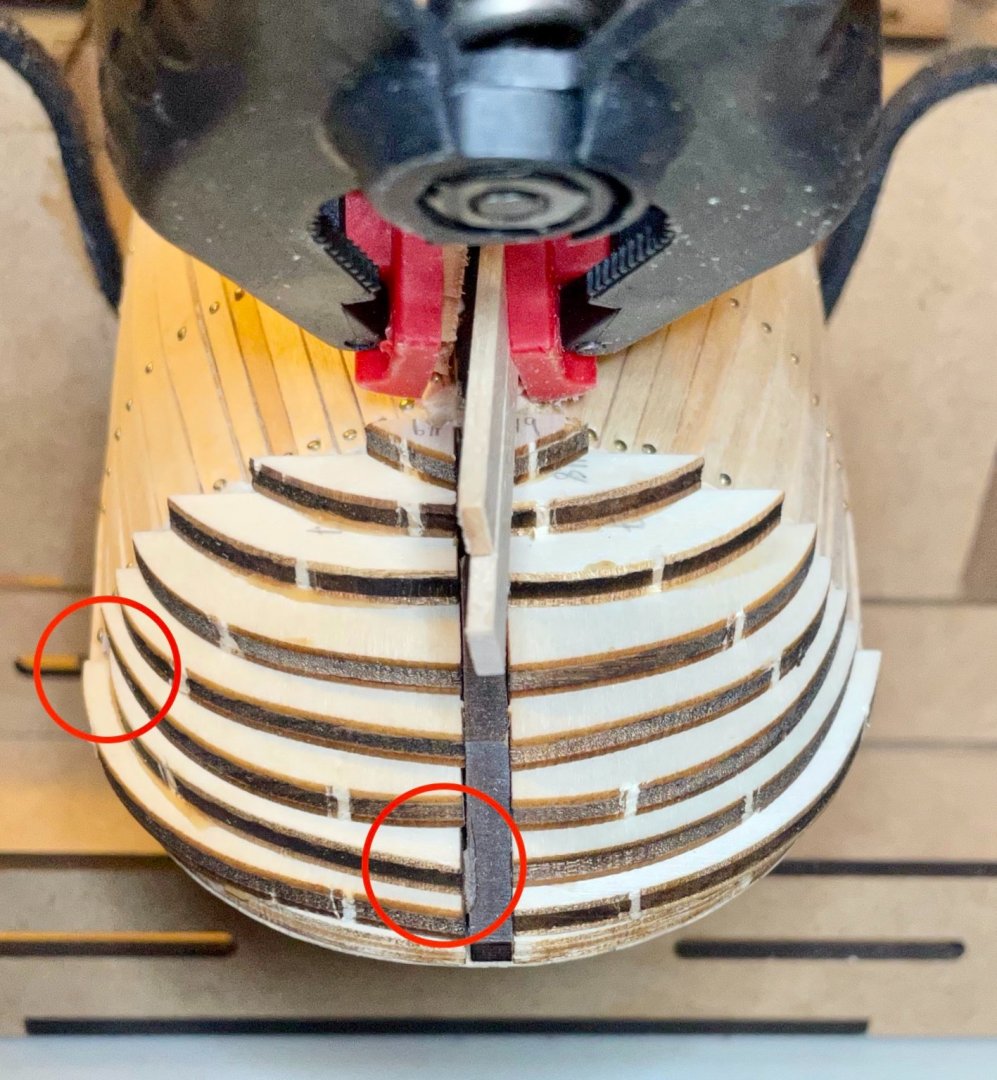
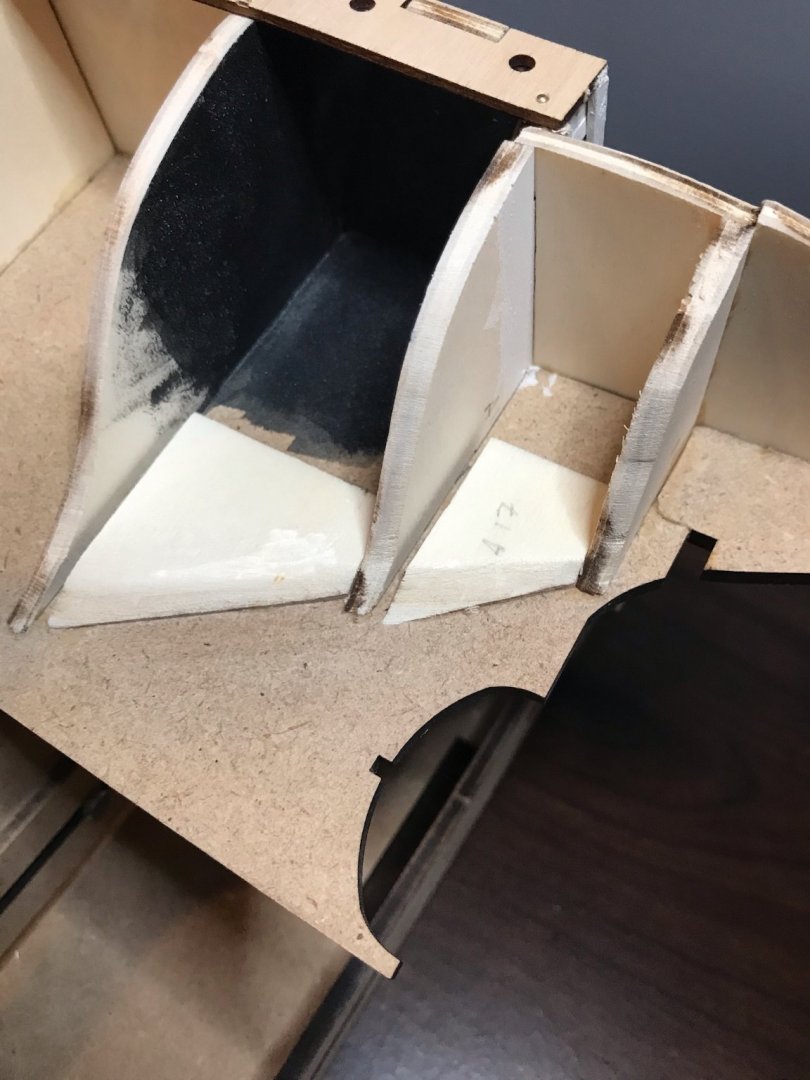
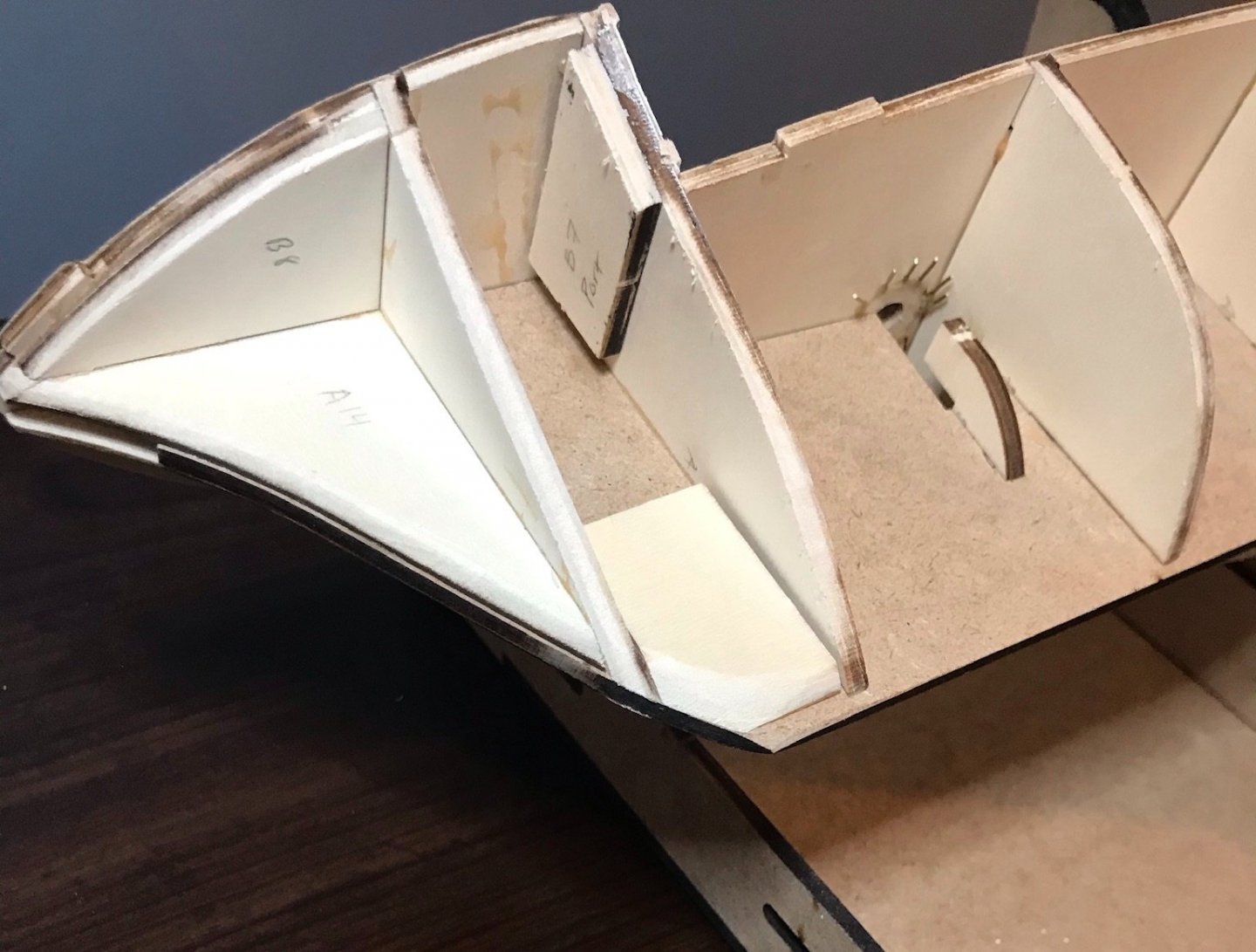
Thanks for the tip, Keith! Here's the link for others looking for those plans: https://prints.rmg.co.uk/search?q=endurance+polaris&type=product. I thought I'd post a quick update while the glue dries on the last of the stealers for the hull. The first planking is done, though there's still a lot of clean-up, sanding, and fairing to do. Everything went really well from the bulwarks to the bilge curve. Coming up from the garboard strake to the bilge curve...well, I'm just not as happy with my work. Because of how rounded the hull is amidships, the shaping of the lower planks is much more challenging at the stem and, especially, in the deadwood at the stern. I've sanded down some egregious spots, but there are some gaps that will have to be dealt with using wood filler. That said, I'm pleased with the symmetry and alignment. This is a case where I think the photos make my work look better than it actually is! Shots are of port, starboard, and overhead (under keel?). Two last notes on the hull, particularly for others who will be building this kit. First: The counter stern is rounded in multiple directions and OcCre has designed it with sixteen plywood blocks that are not covered until the second planking. Once I do the sanding, these will be sanded smoothly with the base planking on the hull. However, since the plywood is so light, you need to be very gentle sanding off the nubs from the laser cutting; I was a bit too zealous on a couple of the blocks and so they don't line up as well as they should with the false keel and the last frame. Second: Some of these blocks look symmetrical, but aren't quite. Specifically: blocks H2 and H3 (the two closest to the aftdeck). Blocks H4 through H8 are clearly not symmetrical, while H9 (the smallest) is a symmetrical right triangle. Keep a close eye on the corners when you dry fit and install these pieces. You'll note that the starboard H2 and H3 blocks (circled on the left side of this photo) are flipped, so the corners don't correctly match the planks and the false keel. I didn't realize that I'd made a mistake here until it was too late and would have had to remove all of the blocks. Things should work themselves out in the sanding, but I will need a bit of wood filler to get the right shape for the corner where the H3 block meets the hull planking. Next step: Trim off the extra bits of the last stealers, then sand and fair the hull.


-
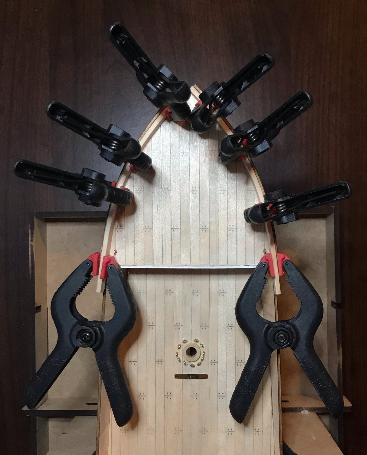
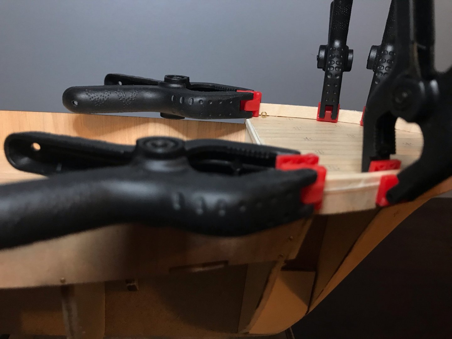
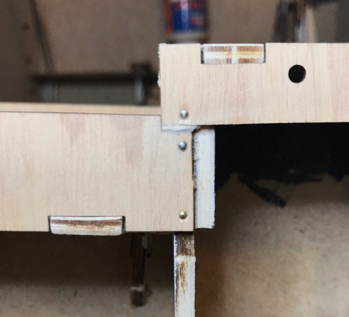
Hi Cathead and Stephen, thanks for dropping in! I'm glad to hear the posts are helpful, since I'm the first one to do a build log of this kit. I hope there will be others soon, especially from some of the more experienced builders who'll be able to bring a lot more "extra" to this kit than I can. Stephen the braces I use for the bulkheads are 1-inch inside L corner braces, something like this. The clamps are fairly simple plastic spring clamps, but I really like the variety of sizes (which are also stronger or weaker as they get bigger or smaller) and the rotating gripping plate (which allows for more flexibility in how they're used). These are pretty similar to the ones I'm using, though mine came as a set of 20 or so in 4 or 5 sizes. I have several tools on my Amazon wishlist (including these); last Christmas, my in-laws generously sent me everything that was sitting on the list, so I'm assuming they actually purchased everything off of Amazon, where you'll find hundreds of options like what I have. As the links show, however, there's nothing fancy about either and you should be able to find something comparable at your local hardware store. Enjoy your Endurance! I've found the kit gratifying so far and hope that you will, too.
-
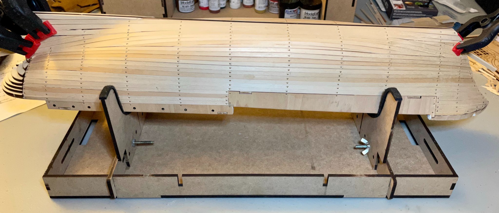
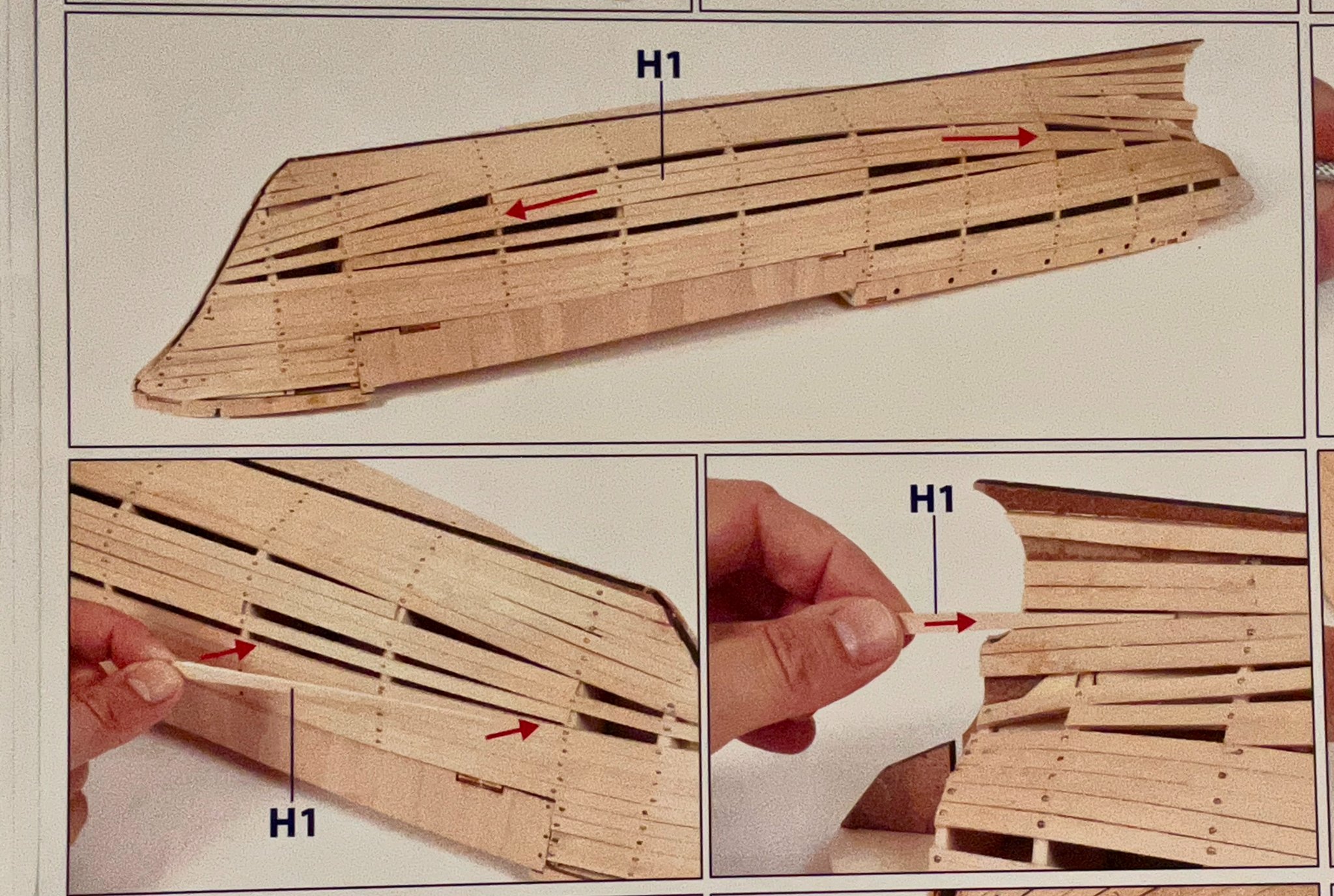
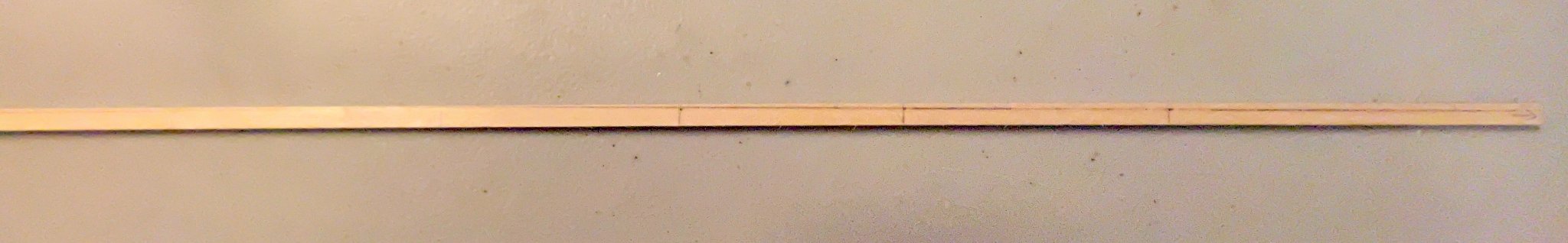
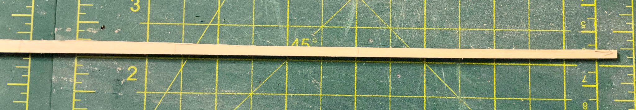
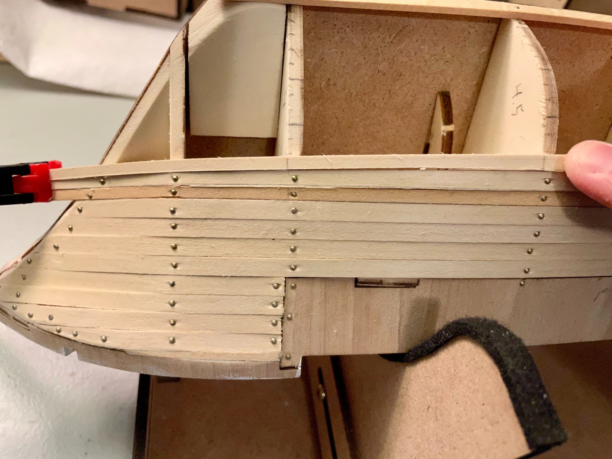
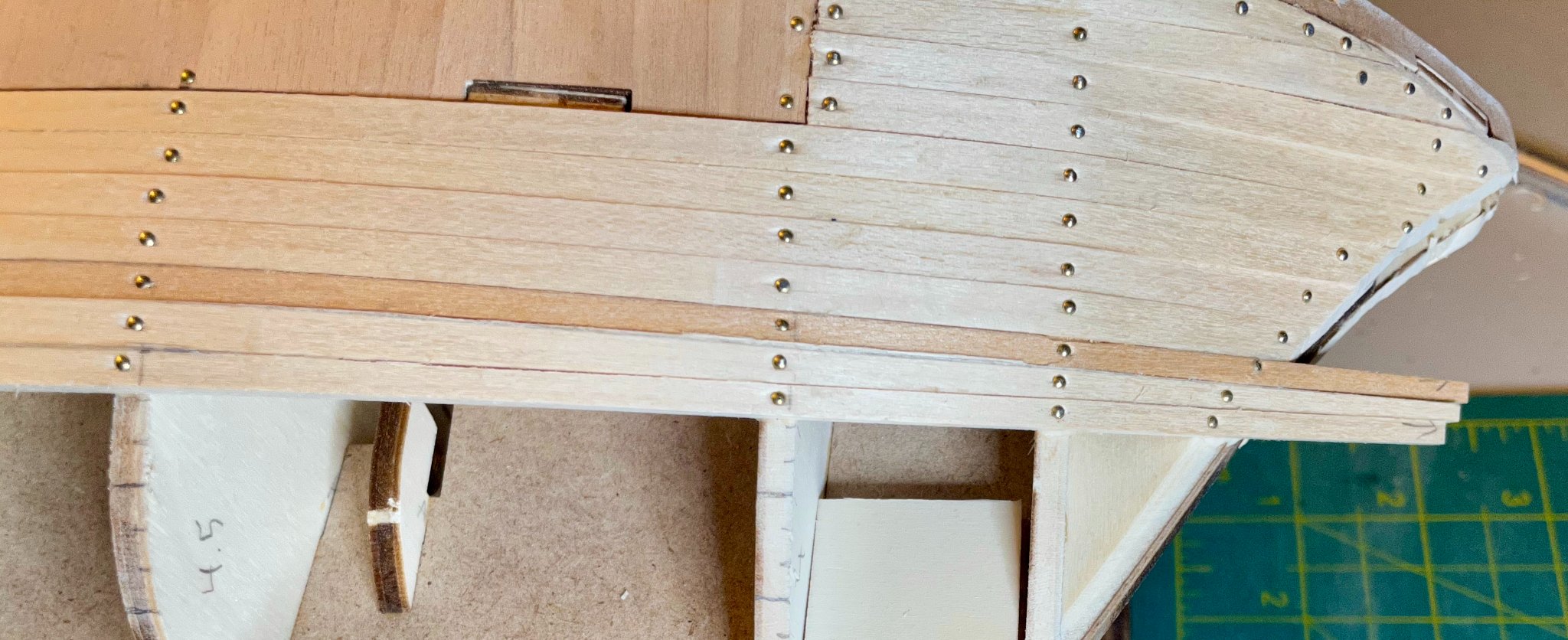
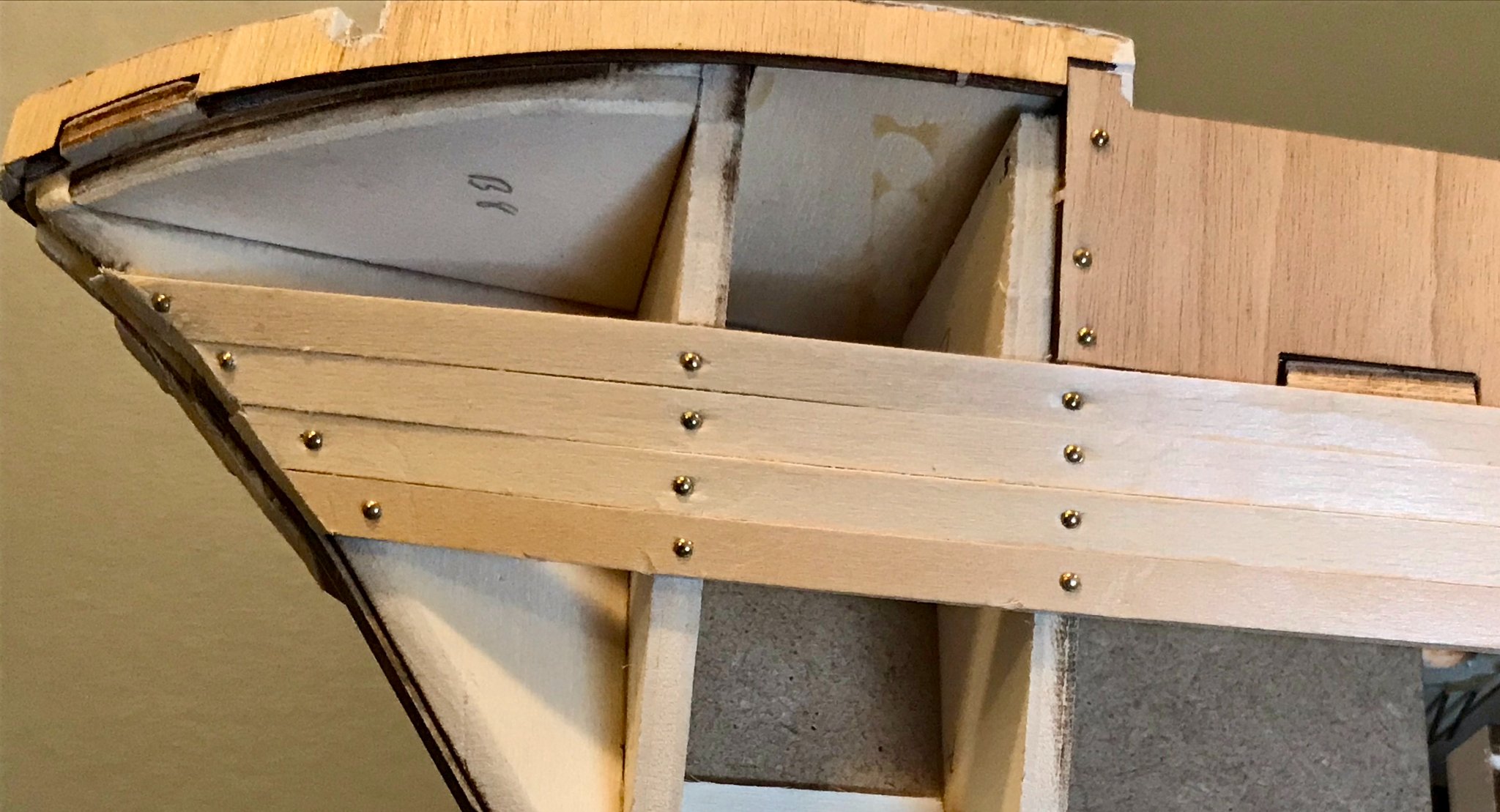
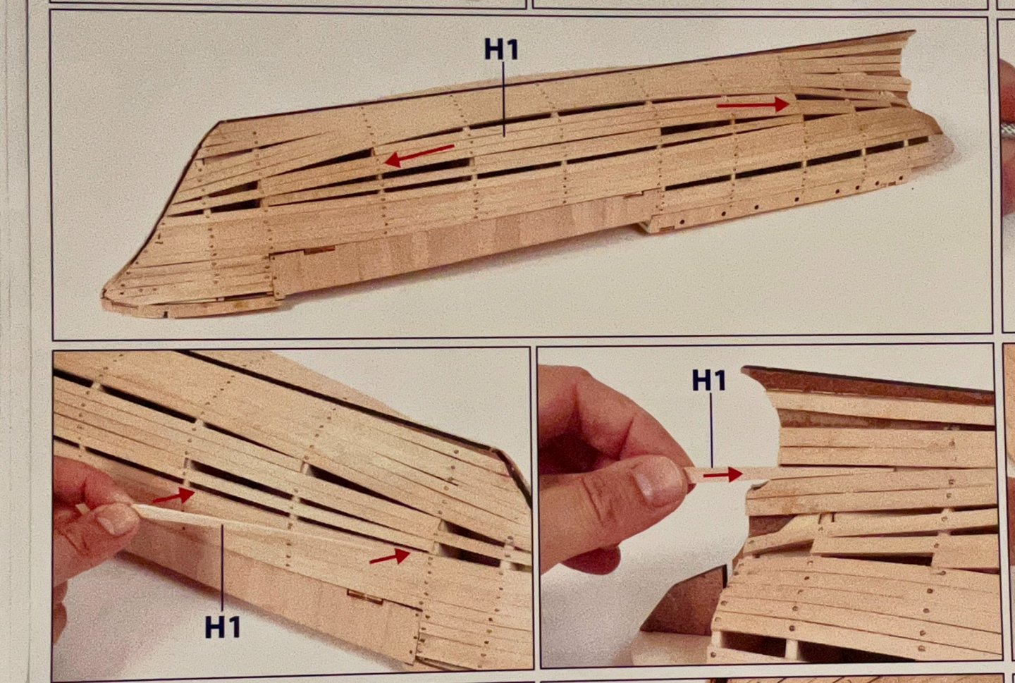
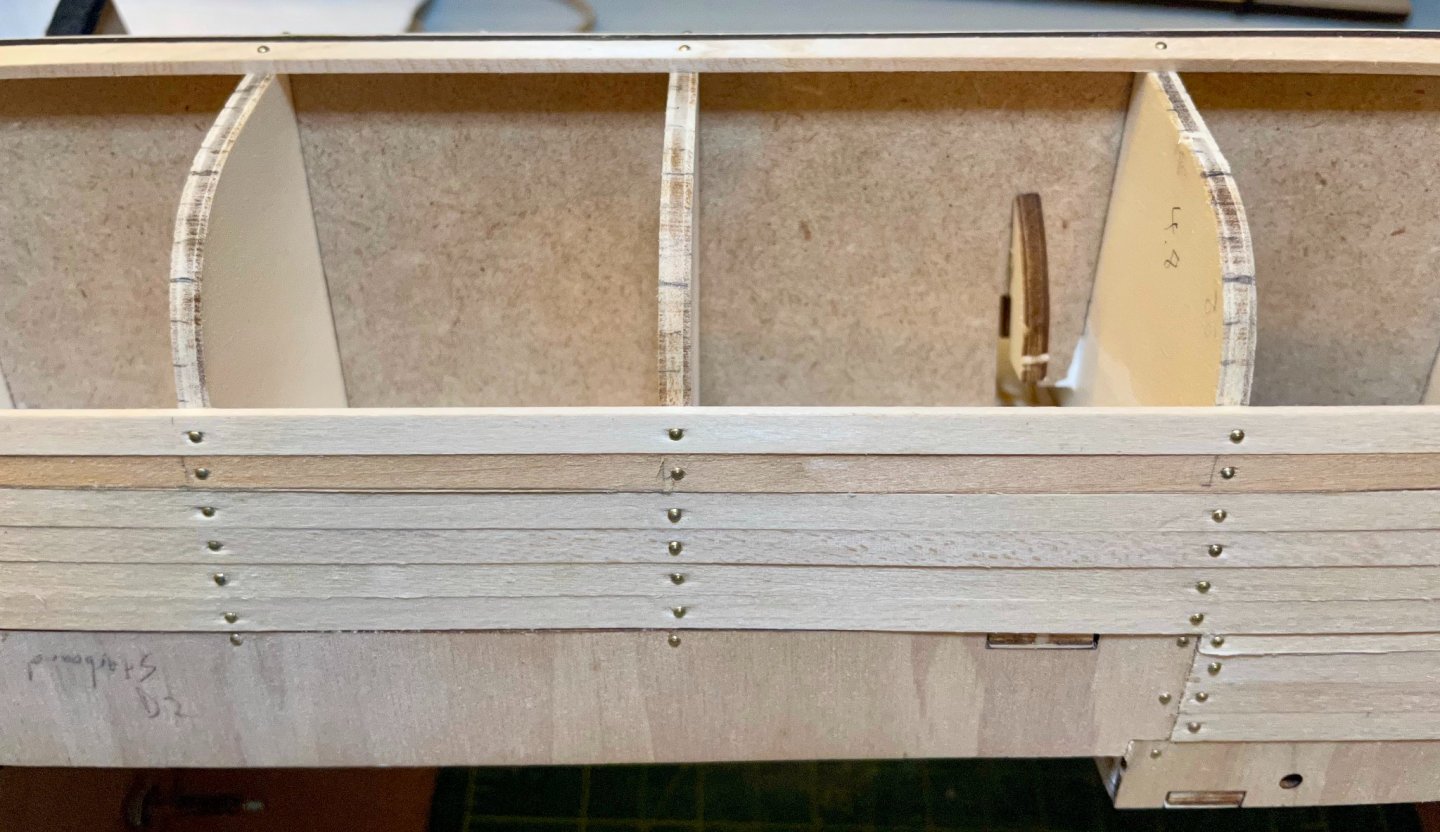
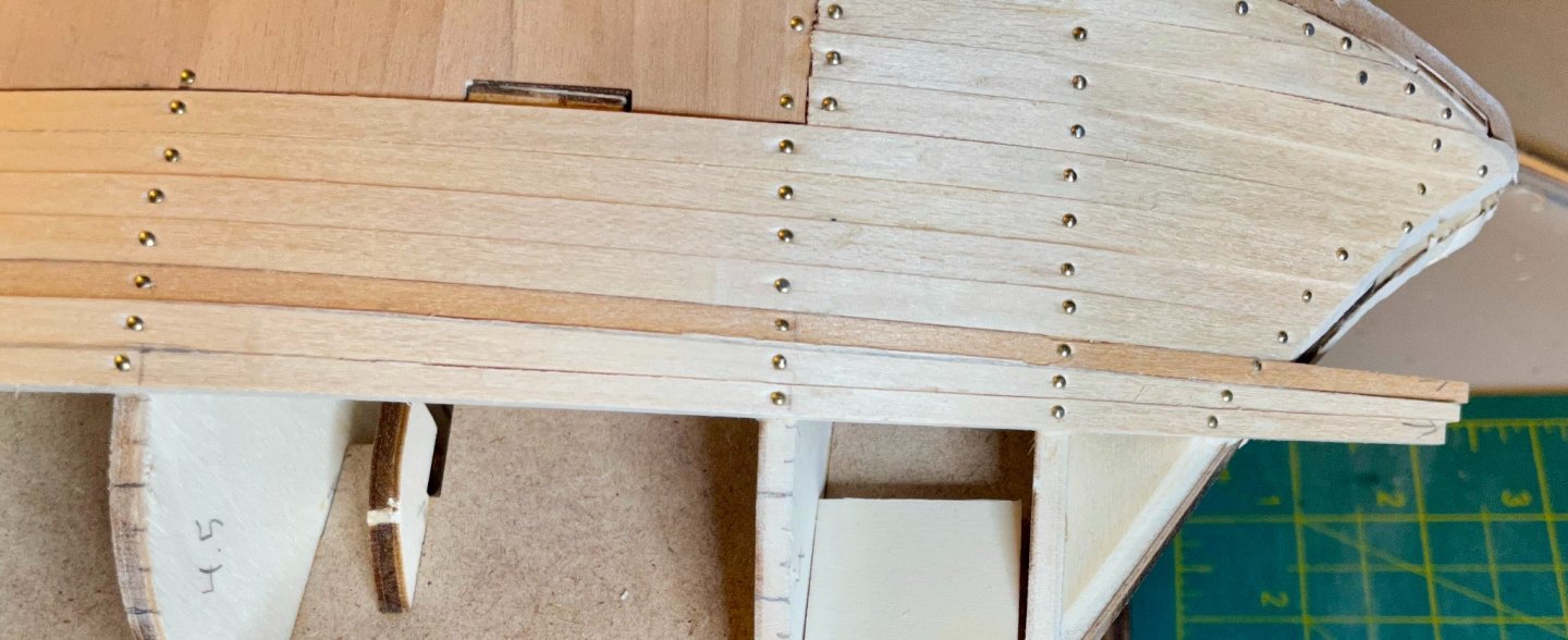
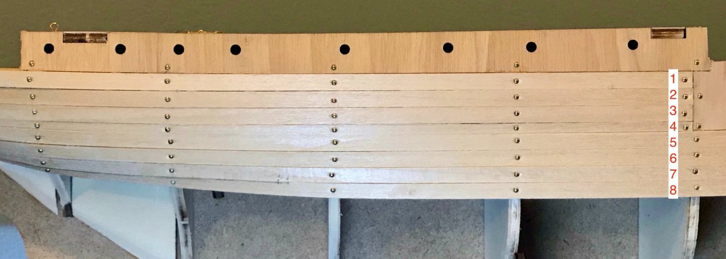
Thanks, Johnny! And thanks for your research and study that you shared on the kit review thread! I think I've found my rhythm on the hull planking. I've decided to not follow the instructions. The approach in the manual and the tutorial videos involves laying all of the full-width planks, then filling in the gaps with wedges (see the image for representative photo instructions). I'm sure this works fine, but I've had a hard time seeing this in my mind and on the ship in my hands. Here's the method I settled on after a bit of playing around and experimentation. First, I lined out the hull on the frames. Well, most of the frames. I'm not quite sure how to handle frames #1, 10, and 11, since they don't extend all the way to the keel. While Chuck Passaro and others recommend dividing the hull into quarters, that's not quite how I've marked it, since I had already laid the planks for the top quarter of the hull. The full width lines are just reference points 5 strakes below the top quarter and 5 strakes above the garboard strake. I've also written the approximate width of the planks at each frame (for example, the "4.8" that you can see on frame #6 in this photo). I mark each plank with a vertical line at the forward edge of each frame, to help me with both shaping and final alignment (there's a bit of glare on the wood, so you can only see the first three vertical lines). I've marked a scrap plank with the required widths at each frame and transfer those points onto the plank being shaped. Next, I connect the dots to mark the shape I need. (The arrow on the right-hand side is to help me remember which end is forward.) A bit of glare again, so the vertical lines are hard to see, but here's the forward end of this plank after cutting and sanding. (The planks are 600mm long, so it's hard to get the whole thing in a single shot.) Next, I dry-fit the plank to check the shaping. One thing that has really surprised me is that I haven't needed to use either heat or soaking to get the planks to lie flat. They just go straight on after being shaped. I'm assuming that this is some combination of: 1) doing a good job of both fairing the frames and shaping the planks, 2) limewood that is both thick (2mm) and of good quality, and/or 3) the absurdly high humidity in my basement after all the rain we've been getting over the last week. Although the dry-fitting doesn't look great here, it's an artifact of using one hand to take the photo. Normally, I spread the fingers of both hands out across several frames to check how the plank is laying. When I attach the plank, I use a generous amount of glue and nail the plank in to each frame, working outward from the center. I've been drilling pilot holes for the brass pins, which I had never done before—this really makes it a whole lot easier and has meant that I haven't broken any planks in the process! Instead, I can hold the plank in place with my left hand, insert the pin into the pilot hole, and then hammer it home. Here are the finished views of this plank at the stern and the stem, where the curviness of the hull make things more interesting; the plank that has been in the previous photos is the bottom one. Still some sanding and clean up to do but that's for another day. Next steps: 10 more planks on the starboard and 12 more on the portside. Since I'm approaching the bilge curve, I'll start working my way up from the garboard strake once the portside catches up to the starboard.


-
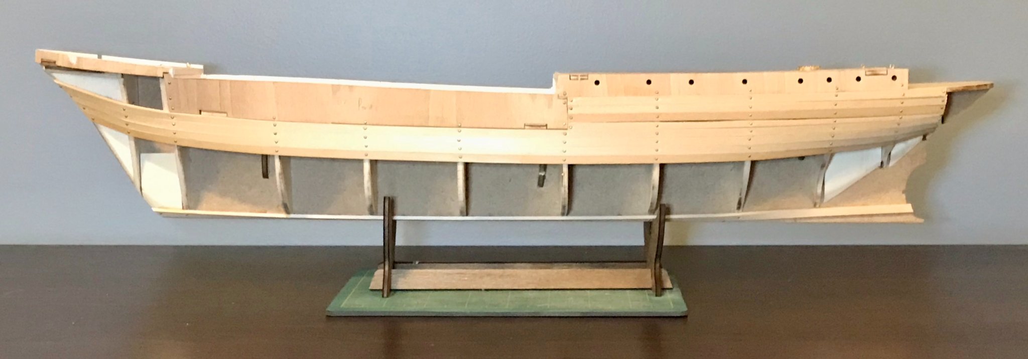
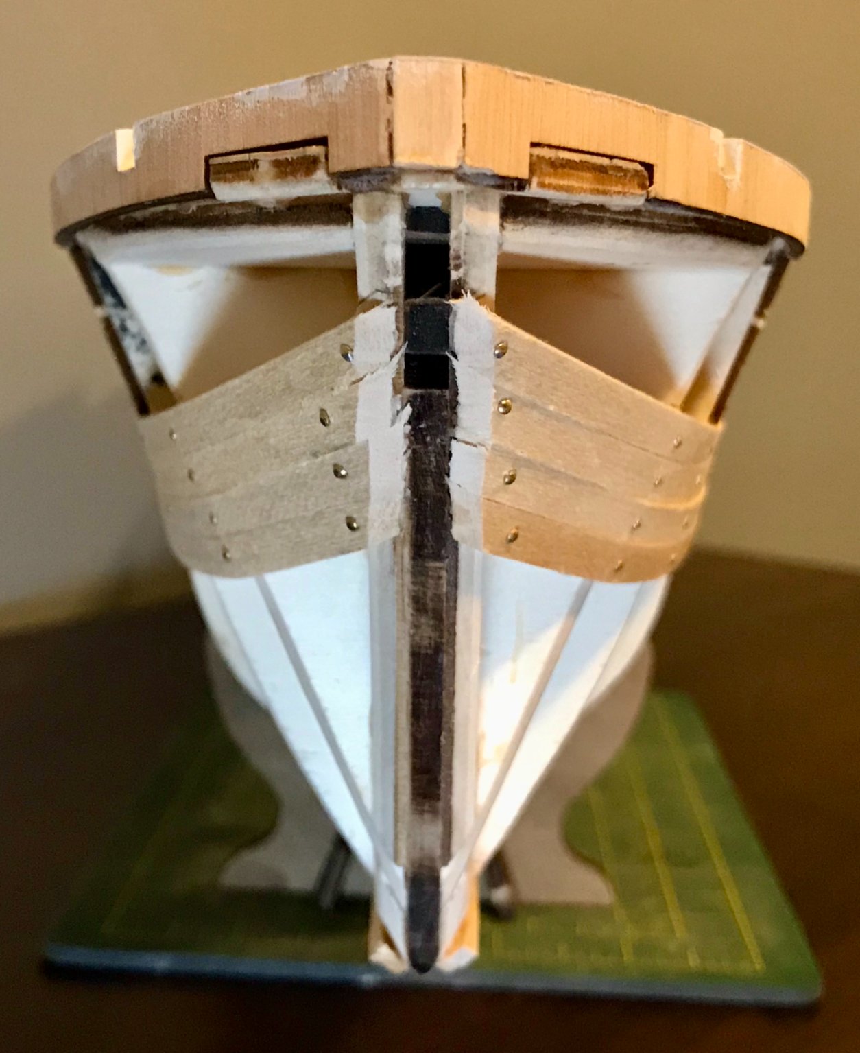
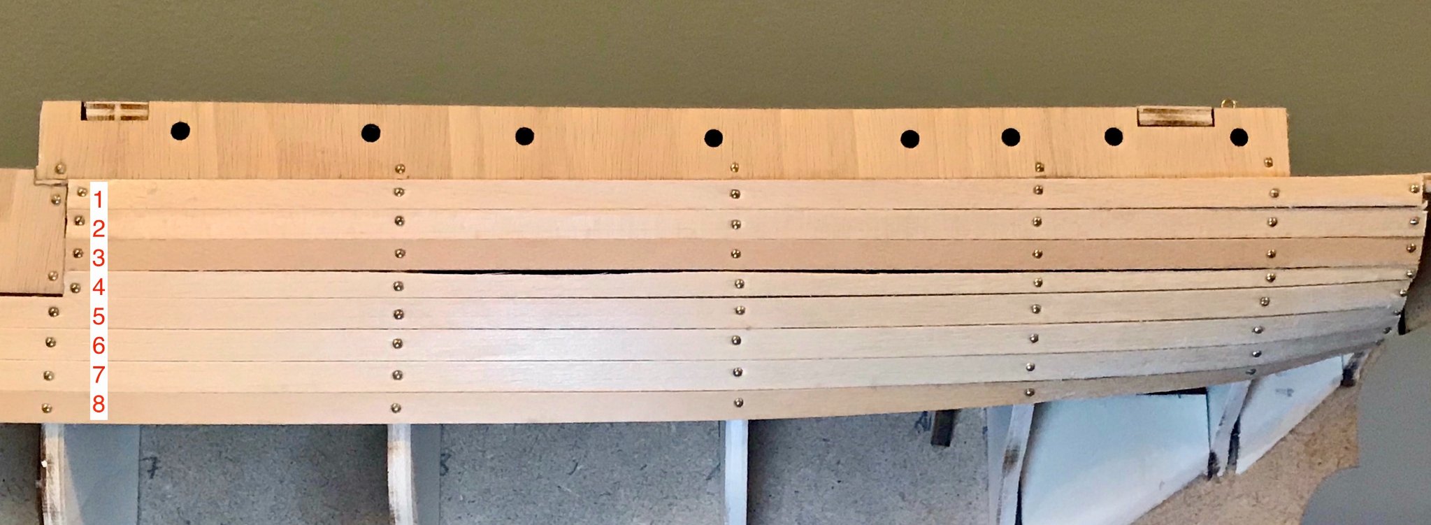
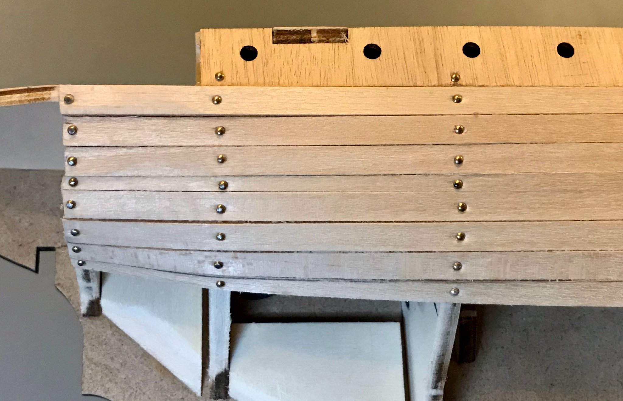
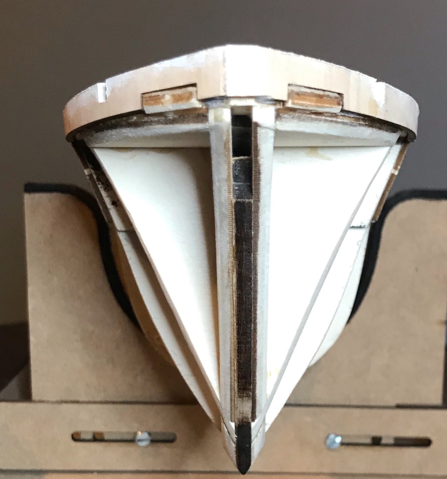
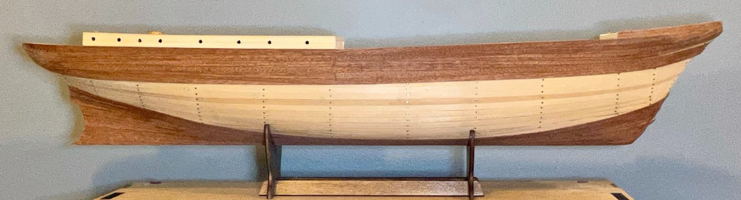
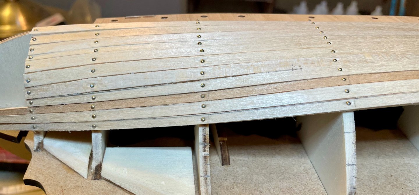
Thanks for the suggestion, Keith! I'm definitely taking to heart the importance of making sure the 1st planking provides a good base. I had a little bit of time last night and played around with the shear strake and the garboard strake. I realized that 1) I had done a great job of fairing the frames and 2) the planks had natural lines to follow that allowed them to lay flat pretty easily. So, I went ahead and attached them. Then, after playing around with the next planks and getting a feel for the lines earlier today, I decided tonight to dive in to the "G" steps (the first four hull planks on each side, #5–8 in the numbered photos below). I worked on the port side first, then starboard...and the improvement from the first to the second was pretty noticeable. I'm particularly pleased with the starboard side, which so far looks better than the final planking on any of my previous kits! It's very gratifying to see my skills getting better. First, some shots of the overall impression: port, starboard, stem, stern. In the shot of the bow, you can see that the garboard planks are not sitting flush at the stem. This wasn't clear until I trimmed off the excess length, so I'd love to know if there's anything I can do about it now—an iron? clamping them with a wet paper towel? just falling back on wood filler and sanding? The shot of the stern shows my improvement from the portside to the starboard. Although the instructions and tutorial videos suggest that these planks can be installed without any shaping, that didn't work for me. The bottom two planks on both sides are trimmed in order to lay flat (or mostly flat on the portside...). However, apart from those two issues, I'm pleased with the symmetry of alignment that I've achieved so far. On to some detail shots of the three critical sections: the bow, under the cabin, and the stern; portside first, then starboard in each case. The natural line for my bow curves upward a lot more than in the instructions or the tutorial videos, but everything's laying flat and reasonably smooth. There's definitely still some sanding to do, but I think this will look pretty good in the end. Below the cabin. You may recall from an earlier post that I had discovered that one corner of the quarterdeck had lifted up by a millimeter, requiring a minor adjustment to compensate. That adjustment is here, with plank #4. You'll note that plank #4 is wider where it abuts the bulwarks on the portside than it is on the starboard. You'll also note I did a poor job of shaping that plank on the portside...sigh...it's not the final planking, so I'm not sweating that. In the instructions and tutorial videos, all of these planks are full width, except for #4, which is fitted into the gap between #3 and #5 (the shear strake). In my case, planks #7 and 8 are trimmed to fit the curve. The stern was the most difficult part of the planking for me and there will be some serious sanding needed to smooth these sections. The planks are trimmed at the last bulwark. After finishing the planking, I'll add 16 pieces of plywood to form the rounded part of the stern. Next step: Finishing the first planking.


-
A bit more progress to report this evening, since I've now finished the "E" and "F" steps. Thus far, things have been rolling along pretty quickly. Chris Coyle described much of the kit as being "rather like a large jigsaw puzzle"; this is definitely true of everything up to this point and that feature makes the kit pretty accessible for even my modest skills. The last part of the "E" steps involved two small pieces lining the deck at the stem. There's a handy template for them in the instructions, but I found the forward angle to be off. While the template has you cut each piece to 45º (so they make a 90º angle, the foredeck bulwarks meet at a somewhat more acute angle. With a little bit of sanding and trial-and-error, I managed to get them in well. (Of course, with the close-up photo I now see that there are gaps between these pieces and the bulwarks. I hadn't picked that up with my naked eye!) The "F" steps focus primarily on finishing the interior of the maindeck bulwarks. The instructions begin by recommending that you paint the full planks before cutting all of these pieces to measure. I'm not sure what some the more experienced builders think of that, but it did help me achieve a more consistent paint job. Two long pieces line the sides of the deck, then there are nine vertical ribs. As elsewhere, the instructions give generous measurements, so I had to trim everything down to fit. As you can see in the first two photos, the forward-most and aft-most ribs are cut to fit around the lining on the bulkheads. I did pretty okay at that, but was able to very carefully fill those gaps with wood filler. After those were solidly in place, I painted the inside of the bulwark and touched up the other painted bits around the maindeck. The last part of the "F" steps calls for placing three planks on each side below the cabin. These run from the after end of the maindeck bulwarks to the last frame (the stern is planked separately). At this point, I'm following the instructions closely, but for more experienced builders, there's an opportunity here to do better. Since there's a definite curve over the last three planks and since the planks are 2mm thick, it took a little work to get these planks to lie well...and there's still just a little bit of a clinker effect that I'm going to have to sand down. Next step: First planking of the hull. Things have come together quickly so far, but are going to slow down now. As Chris Coyle mentions in his review, the instructions call for a "Mastini-like simplified method"; I'm still enough of a beginner that I have to take his word for that. But it is definitely a different approach than what Chuck Passaro recommends in his planking tutorial (text/photos and video). One of my goals with this kit is to have a better hull than I accomplished in my previous kits; since I'm painting the hull, I know I have a bit more flexibility in terms of planking method. I think my current skill level is probably better suited for the simplified method, which requires less planning up front, but Chuck's method seems to make it easier for me to see the hull before I build it. I managed to line off the largest frame on each side; conveniently, they fit exactly 17 planks. However, I'm confused about how to line off the frames as I approach the curves of the bow and stern. Still a bit for me to work out in my head before I attach any planks, so advice is more than welcome!

-
A bit more steady progress to report. I've attached the bulwarks on the main and foredecks. This was one of several steps that I was nervous about, since the risk of breaking pieces is high. In fact, I did snap in half the portside bulwark on the foredeck—yikes! The break happened at a skinny point under the cable channel. After panicking and looking up the possibility of replacing broken parts (the form is here if you need it), I decided to put on some Gorilla glue and see what happened. As luck would have it, the glue held, even through the shaping process! *phew* Apart from that scare, this process went more smoothly than I anticipated. The maindeck bulwarks have to be shaped with a pretty significant twist (nearly 45º), which I accomplished by soaking the plywood pieces and then borrowing the Admiral's clothes iron. The foredeck bulwarks, unsurprisingly, have a dramatic curve, which I handled in the same fashion. When I attached the maindeck bulwarks, I had another crisis moment—after lining the bulkheads, I had had a sneaking suspicion that something was out of alignment. Once I started dryfitting the bulwarks, I confirmed that suspicion. One corner of the quarterdeck was about a millimeter off of the frame to which it had been glued. After considering my options, I decided to just live with it and to cover it as best I could. The alternative would have involved pulling off one of the main cabin bulwarks (both glued and nailed into place) and stripping the lining on the bulkhead; way too much potential for irreversible damage there. So, I put in a shim to fill the ~1mm gap between the two bulwarks. Given how the planks lie on the hull, there will be a very small and (hopefully) subtle adaptation that I make, but this shouldn't pose any serious problem down the line. (Famous last words, I know...) Photos are of the maindeck bulwarks, the shim on the portside (which still needs a bit of clean-up before hull planking begins), the foredeck bulwarks, and an overhead shot of all four pieces. Next up, I needed to line the foredeck bulwarks with pieces of 2x5 limewood. Another round of soaking and ironing made pretty quick work of this, though I also clamped them into place when I installed them. The next challenge was shaving, sanding, and filing them down to match the precut plywood pieces. Then, I added the stem head (the stem itself is a precut walnut/plywood piece that comes later). The instructions call for this to be cut as a trapezoidal prism, but that left a pretty big gap between the bulwark pieces. Instead, I sanded it into a triangular prism and it slid satisfyingly into place. Photos show the two lining pieces clamped into place, then two different angles showing the shaped lining and the stem head (which at that point still needed a little sanding attention on the starboard side). Finally, I've painted the foredeck bulwarks. Still a bit of final sanding to do after the last coat of paint dries, but I'm overall pretty pleased with how this turned out. Next steps: I'll wrap up the "E" and "F" steps by lining the edges of the decks against the bulwarks and by adding the support ribs to the maindeck bulwarks. After that, the hard work of hull planking begins!


-
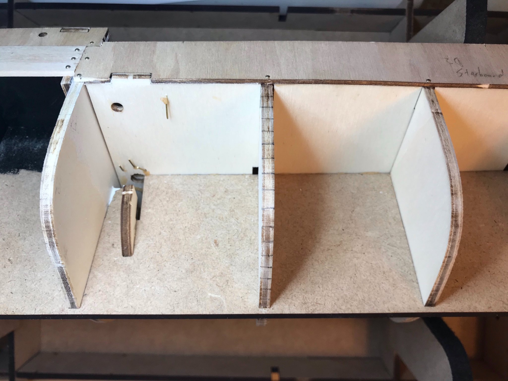
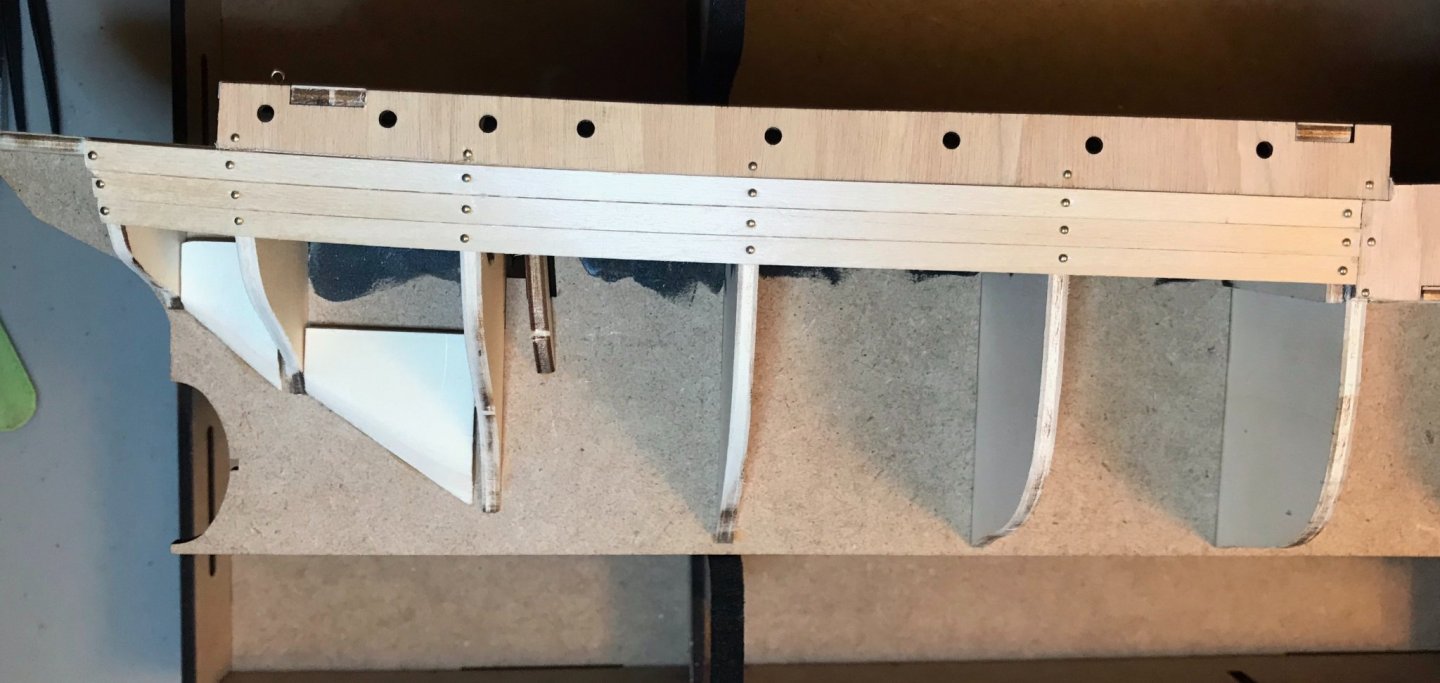
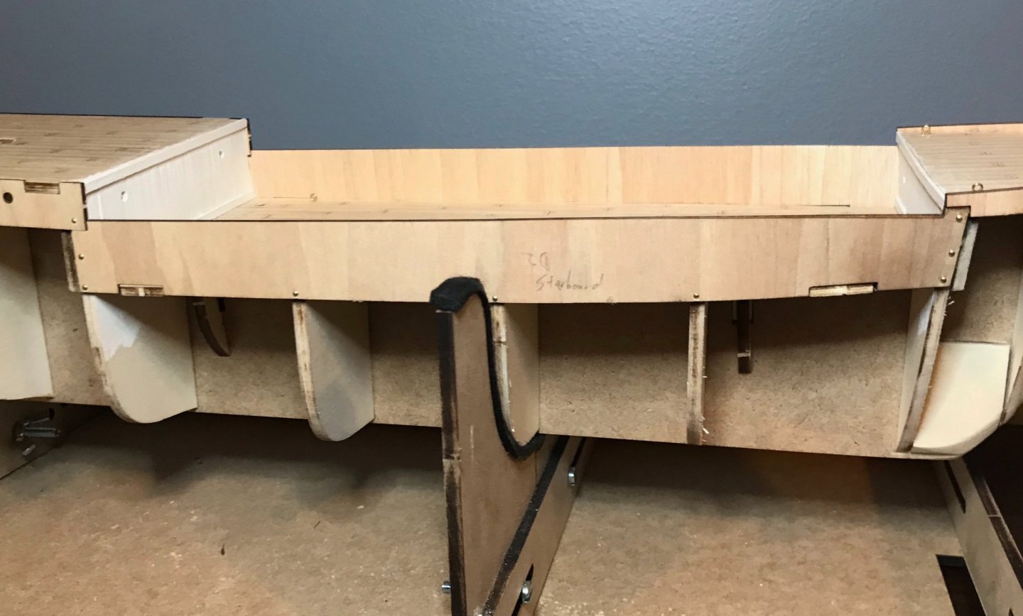
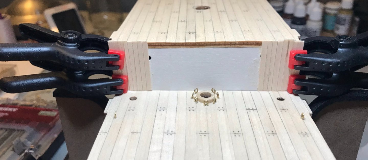
Johnny—I look forward to your build log! Glad to hear that the false keel arrived intact for you, too. By the way, for those interested, the Royal Museums Greenwich have poster prints of the original drawings of the Endurance; you can find them here, along with a few of Frank Hurley's photos. Ian—Thanks for the recommendation! That one's on my list, though I haven't gotten to it yet. For other recommended books, here's a list put together by Shackleton's descendants. This has been a lovely weekend for working on the Endurance. With thunderstorms rolling in and finals week ending, I got the mowing done early and then spent the rest of the weekend taking breaks from grading to work on the ship and vice versa. So, some nice progress to report! After finishing the lining on the bulkheads, I added crosspieces at the top and bottom. The top pieces are part of the "C" steps, but the bottom pieces are actually part of the "E" and "F" steps, after the bulkheads have been added. I'm really not sure why the delay is recommended—it was certainly easier to put them in now and sand the ends down to match the frames, than it would have been after the bulkheads were already in place. (Note: I realized that I had been messing up my terminology. From here on out, I'll correctly be using the terms "quarterdeck" instead of "aftdeck" and "aftdeck" instead of "poopdeck." Still learning...) The instructions never call for a lower cross piece for the bulkhead on the aftdeck, but that just didn't seem right to me, so I added one. Compared to the real ship, these are probably all out of scale, so they may be an opportunity to consider for those interested in upscaling the kit. The photos are of the forward bulkhead on the maindeck, after bulkhead on the maindeck and the forward bulkhead on the aftdeck. The other part of the "C" steps involved fairing the frames in preparation for lining the deck. Fairing the hull is one of the areas in which I'm trying to improve my skills with this kit. (I've learned a lot in the last couple months by watching Leo Goolden's rebuild of the Tally Ho and so I feel like I understand the process a LOT more than in my previous kits.) The instructions wisely call for using a test strip to check as you work. They don't call for balsa blocks to fill all of the gaps at the bow and the stern, but instead the kit does add several plywood blocks in those places. For now, at least, I am thinking that those blocks will be enough, but we'll see. For those doing the kit, frame #9 (piece A10) was a bit undersized through the bilge, requiring me to really sand down frames #8, 10, and 11. I also recommend a rounded sanding black, as shown in the tutorial videos; sanding those extra plywood blocks at the stern is very awkward! I'm sure there's more sanding to do once I get down to the nitty gritty of planking, but for now I'm reasonably happy. I'd love to sand a rabbet line into the false keel...but I just can't make a dent in it. The material is MDF, I think, but it's resisted my sanding efforts so far. Photos are close-ups of the port bow and port quarter. (Note, the black paint is for those spaces inside that have portholes. I'll be adding more in the main cabin soon. This is my own aesthetic, rather than anything in the instructions.) Finally, I moved on to the beginning of the "D" steps by attaching the bulwarks for the main cabin. Photos are a detail of the portside bulwark and then a shot of the whole ship as she currently stands. Next steps: continue working my forward with the bulwarks.

-
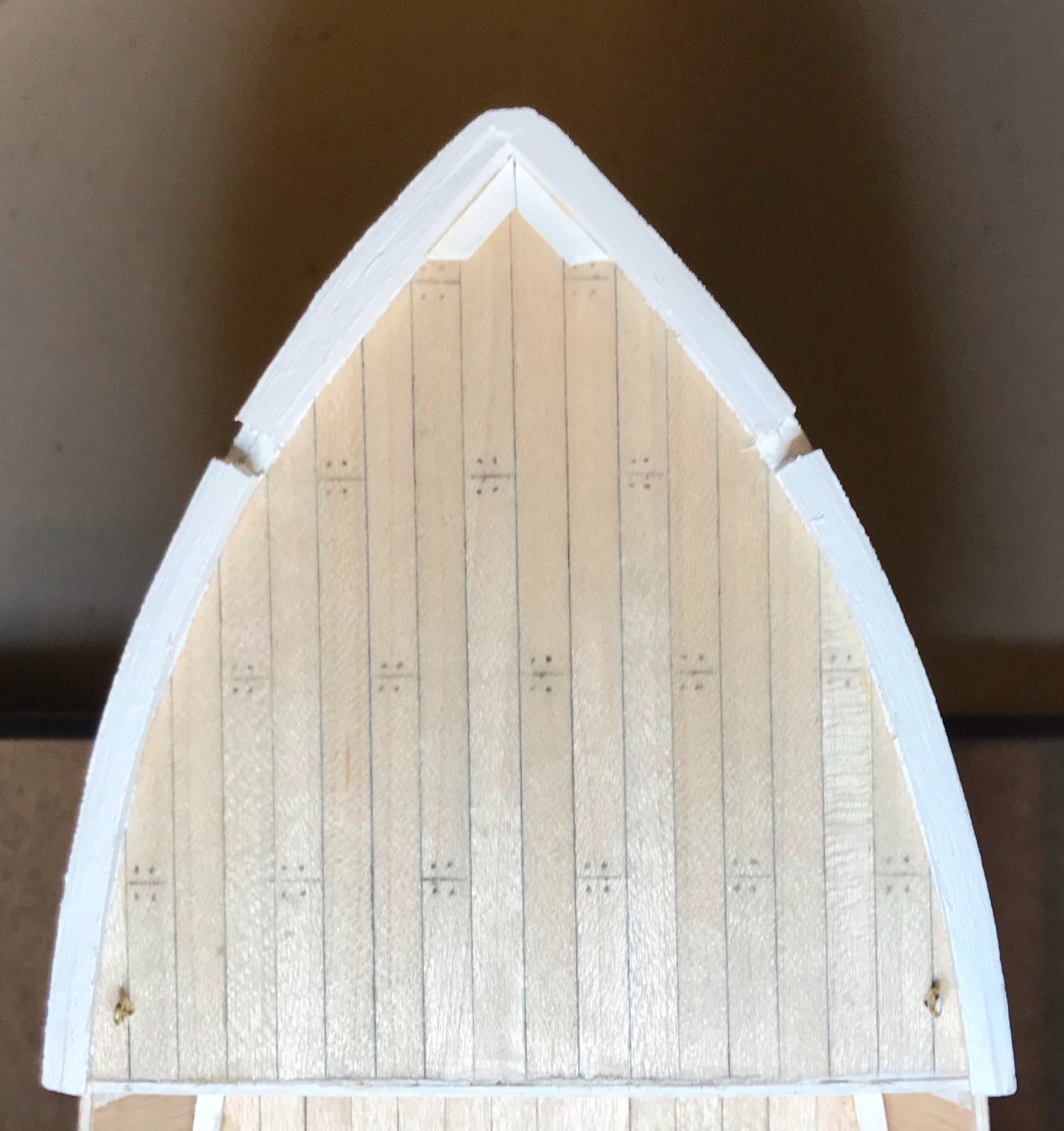
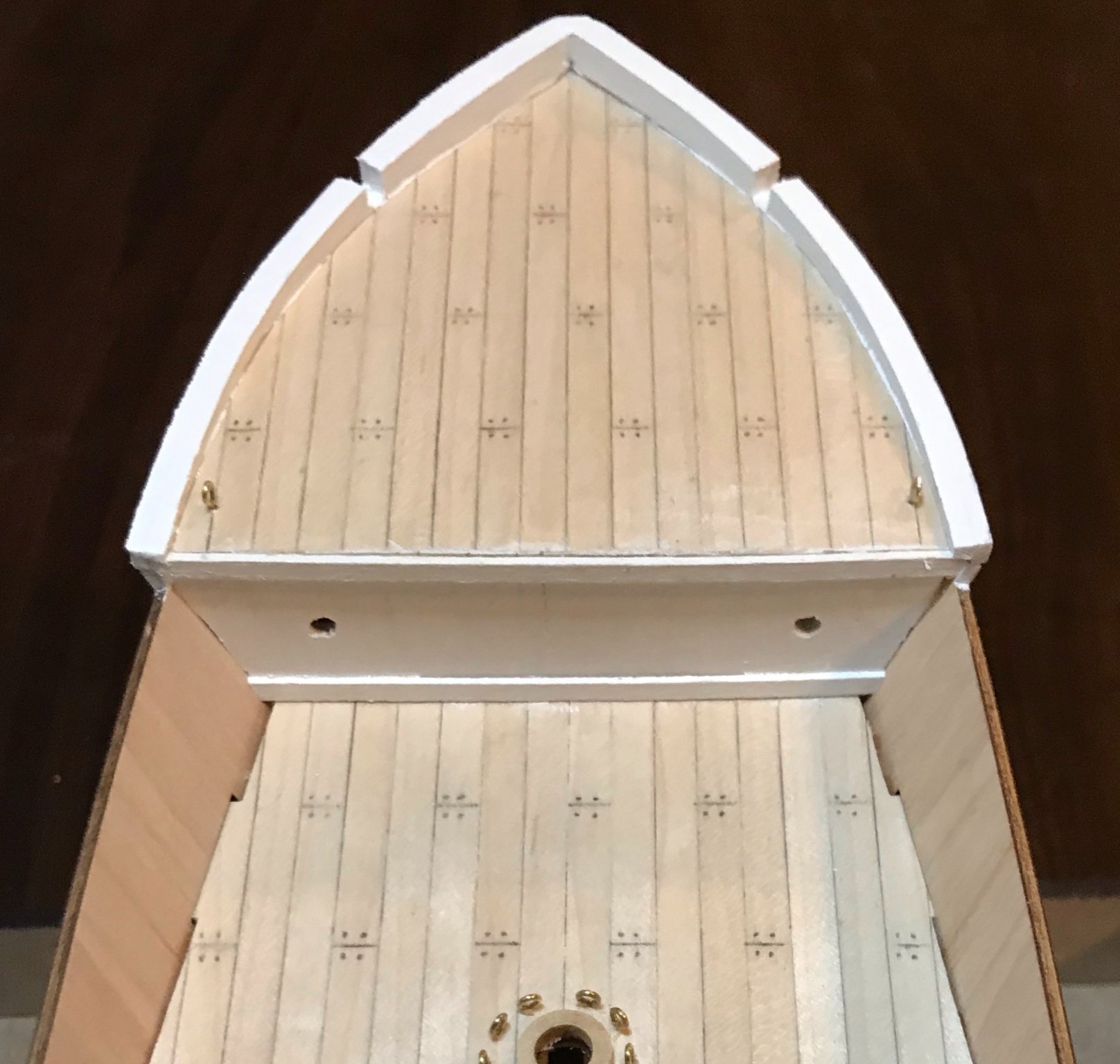
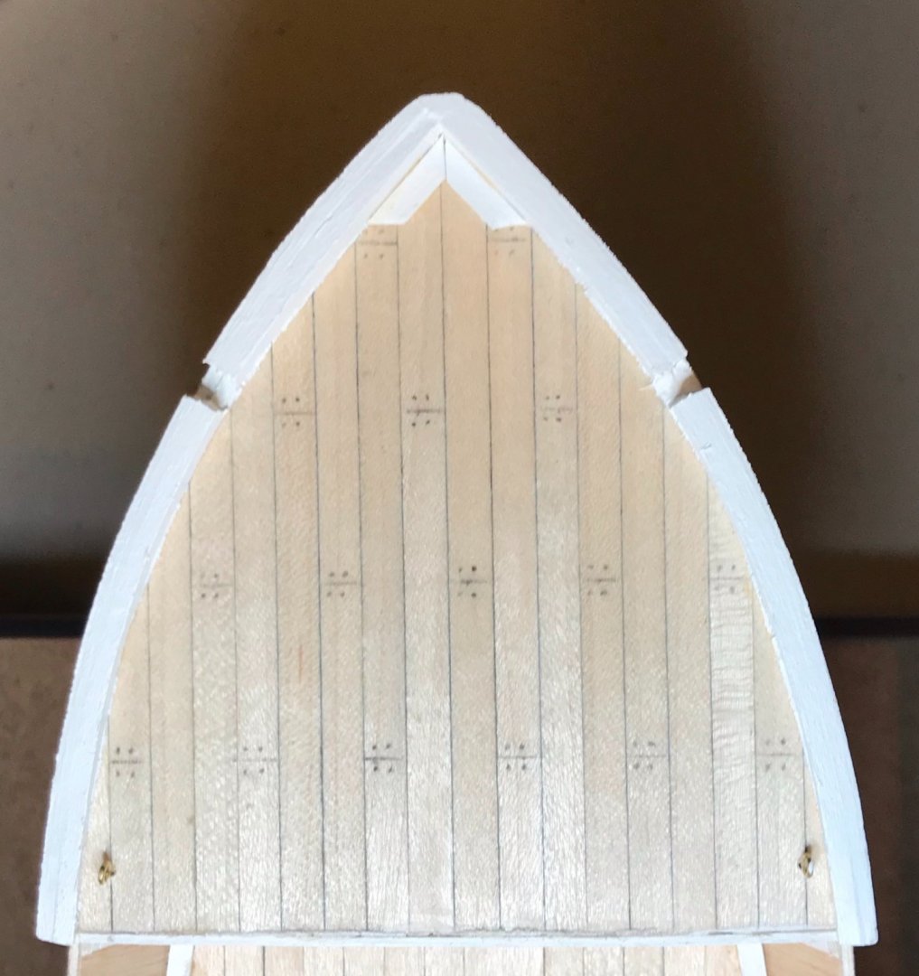
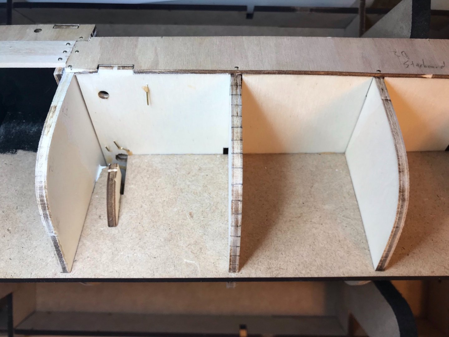
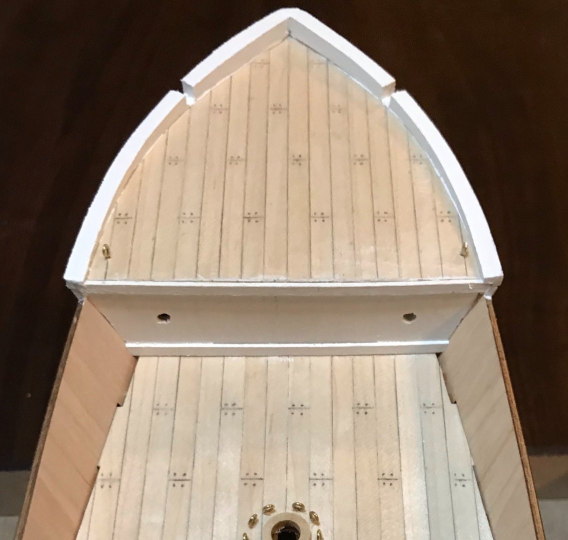
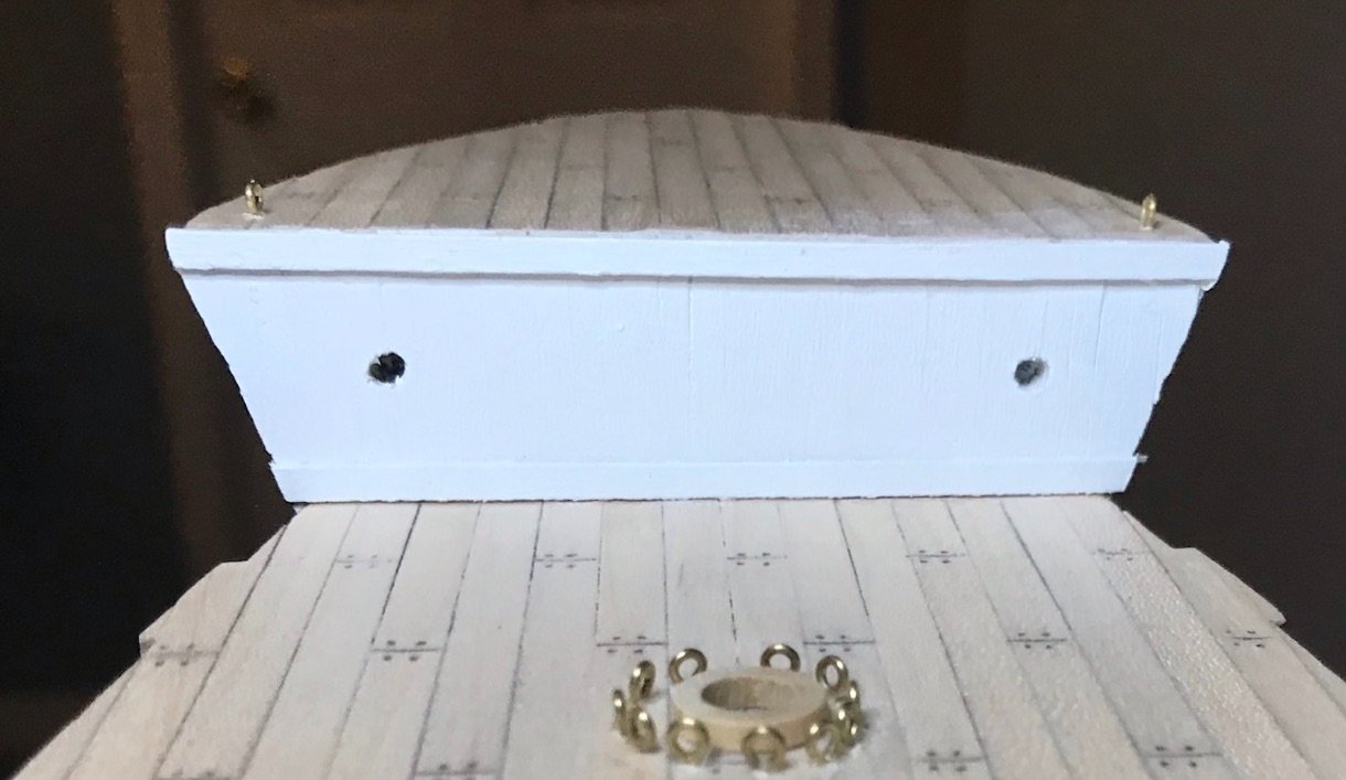
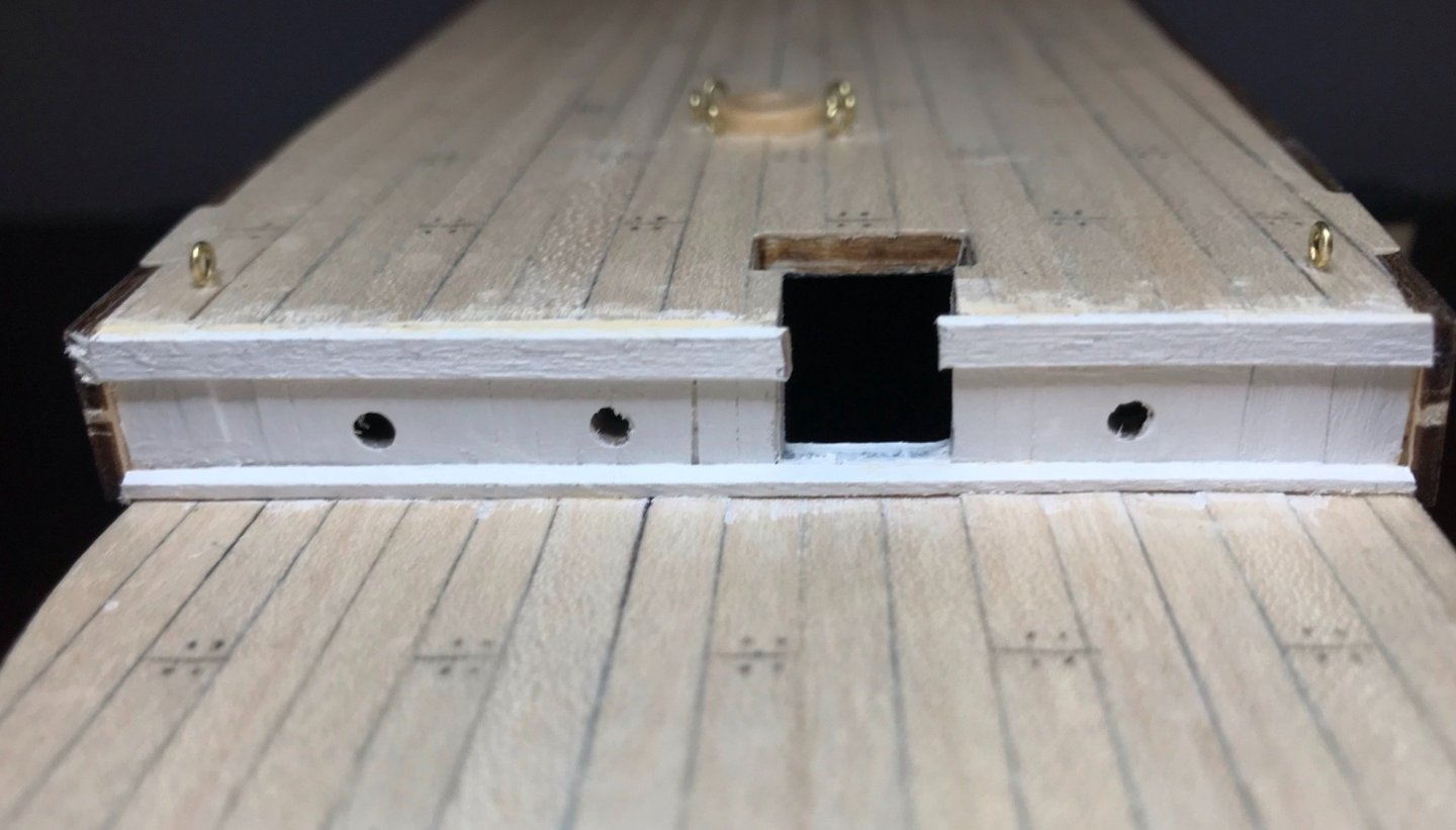
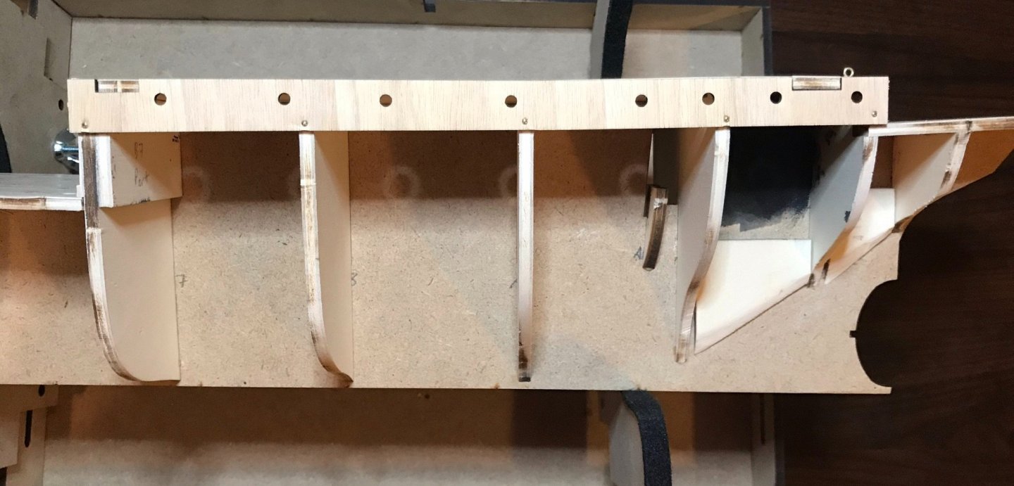
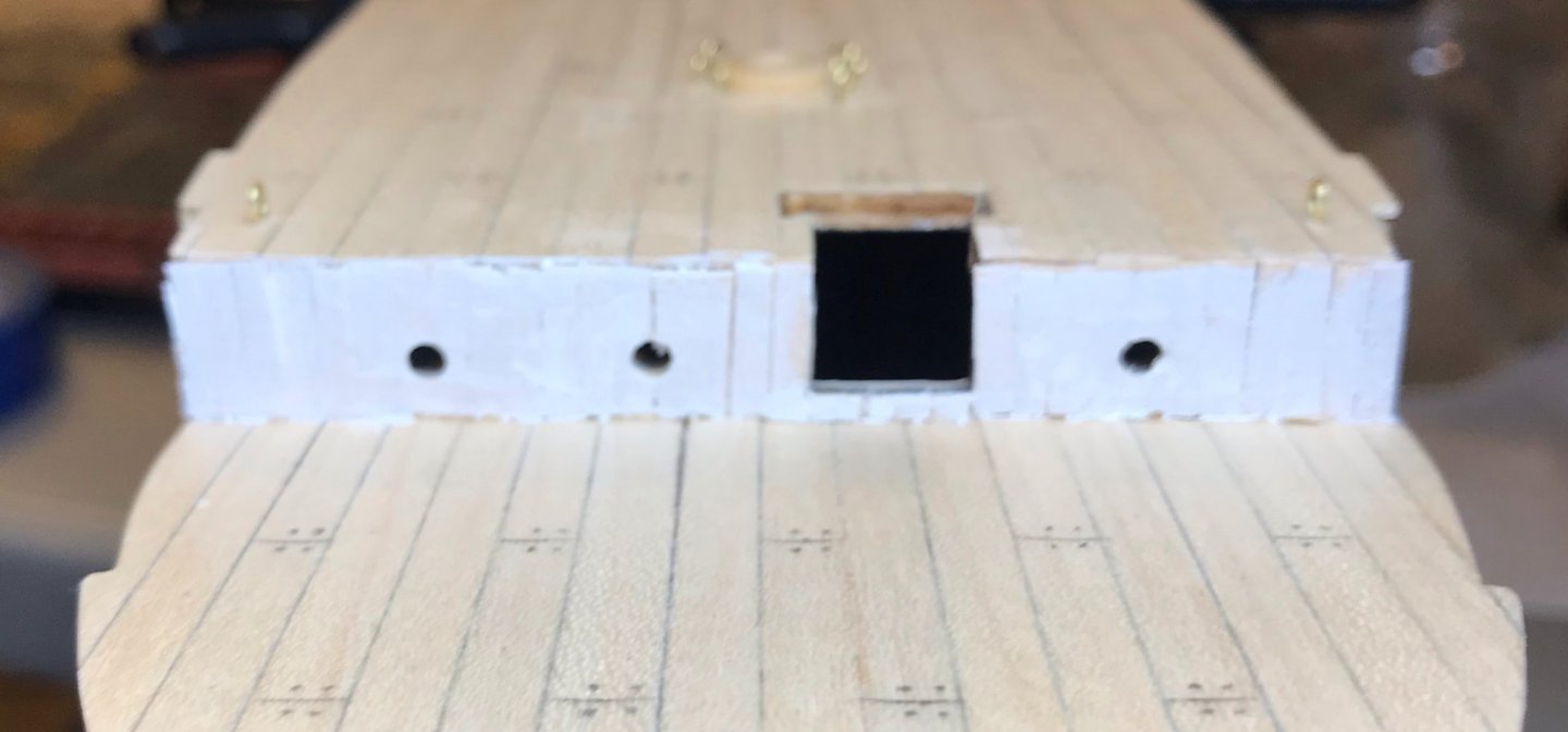
It's been a really busy week here, so I've been glad to squeeze in some time working on the Endurance. I finished the "B" steps, which involved attaching the four decks, along with six additional blocks that will help once it comes time to do the hull. I've also spent time browsing GettyImages.com for more of Frank Hurley's photos of Shackleton's expedition—there's a treasure trove in there, especially for those looking to upscale this kit. This link will take you to a gallery of photos tagged with "1914–17 Imperial Trans-Antarctic Expedition," but a more general search for "Shackleton" and "Endurance" brings up 800 hits; some repetition of images, and not all directly related, but some additional treasures for sure, including some photos while the ship was still in drydock (even some before it was painted!). Of particular interest for me this week are those showing the bulkheads on the main and poopdecks: A photo of the crew posing on the foredeck, seven days before the ship was stuck in the ice; the forward bulkhead on the maindeck is visible. A photo of several men working to break up the ice, just before the ship was stuck; again, the forward bulkhead on the maindeck is visible. A photo of Tom Crean taking care of the dogs, in their kennels on the aftdeck; the forward bulkhead on the poopdeck is visible. A photo of the Endurance being crushed by the ice, the after bulkhead on the maindeck is visible. After studying these photos, I decided I had to upscale the kit a bit by lining those three bulkheads. The bulkheads are, of course, the upper portions of three frames. The instructions call for them to be sanded smooth, then painted white. Crosspieces at the top and bottom, portholes, doors, and other bits are added later on in the build. That looks a bit like this shot of the forward bulkhead of the maindeck (the paint job looks so bad because I had already roughed it up a bit in preparation for gluing planks onto it). The flat white look is okay, but after looking at the photos, I just wasn't satisfied anymore. I'm using the same sycamore planks used for the deck, since the kit generously provides a few extra meters of these. However, I'm also slicing them in half to reflect the narrow boards shown in the photos that I linked to above. The exercise has really stretched the limits of my skills. I did the forward bulkhead on the poopdeck first, figuring it would be the easiest. I'm pretty sure I was wrong about that, since I broke a few planks while drilling and filing the portholes and since these very small pieces (2.5x12mm, 2.5x1.5mm at the hatchway) were a real pain to work with. For that bulkhead, I laid all of the strips, then did the portholes. For the bulkheads on the maindeck, I'm laying strips only up to the portholes for now; once I've cleaned that much of the portholes, I'll add the rest of the strips. These portholes will be a little bit of a challenge—since there are extra blocks behind them to give more purchase for the bulwarks and hull planking, I won't be able to run the file all the way through the holes. This way, I can hopefully do most of the work with my Exacto knife. The next two photos are of the partially lined after bulkhead on the maindeck and of the forward bulkhead on the poopdeck, which already has primer on it. The top and bottom edges look a little rough, but those will be covered soon by crosspieces.
-
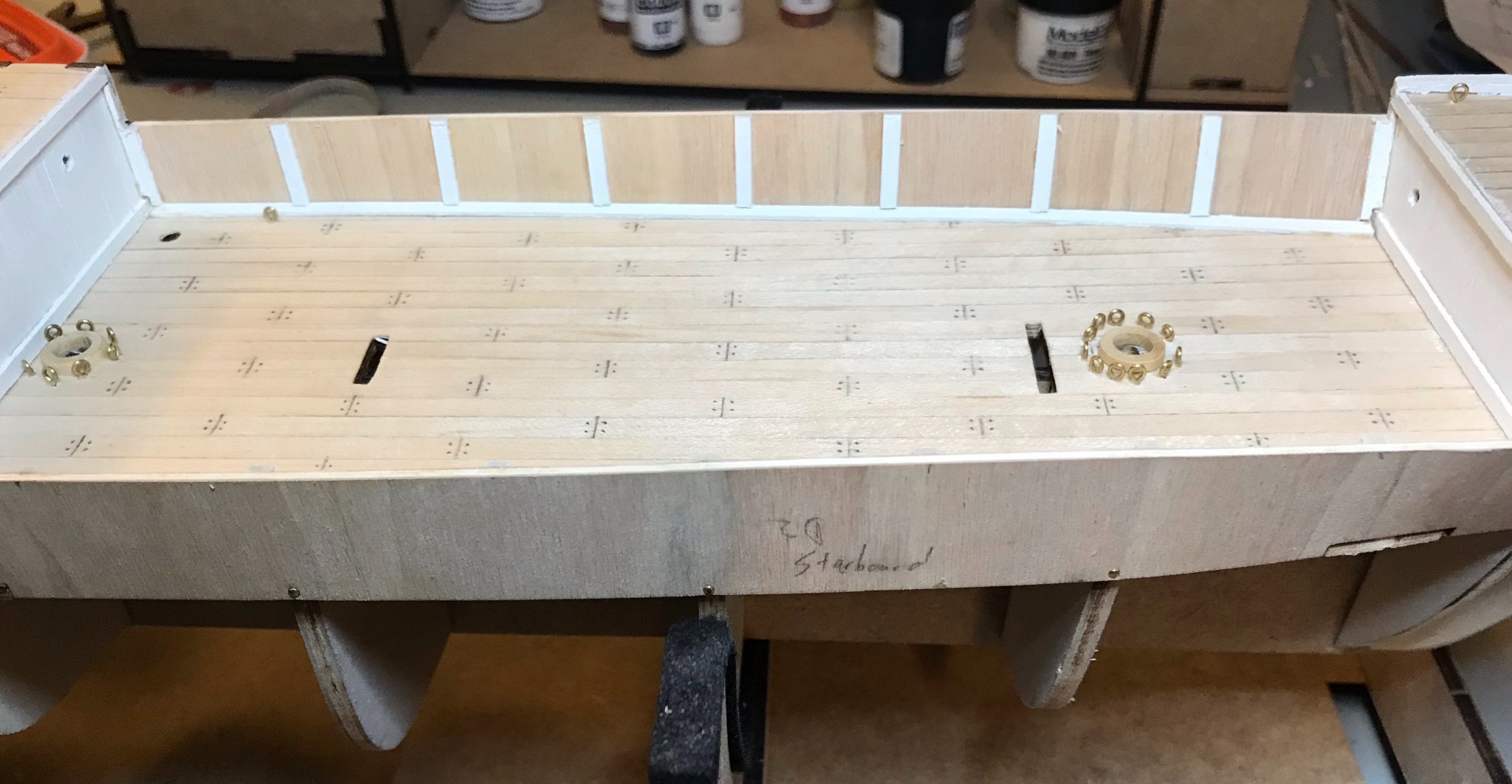
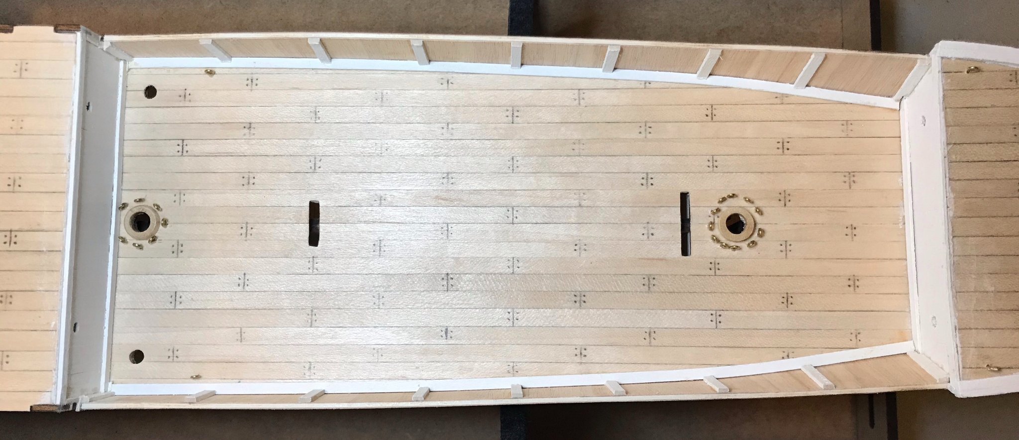
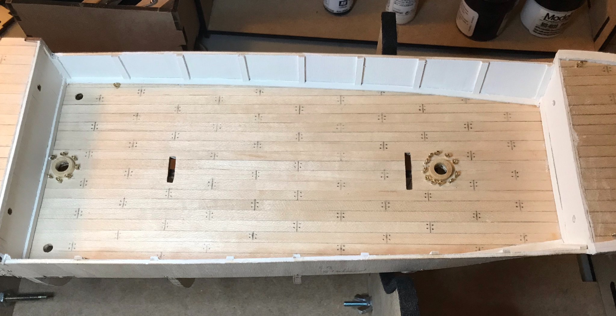
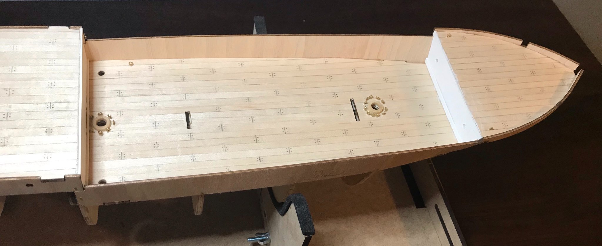
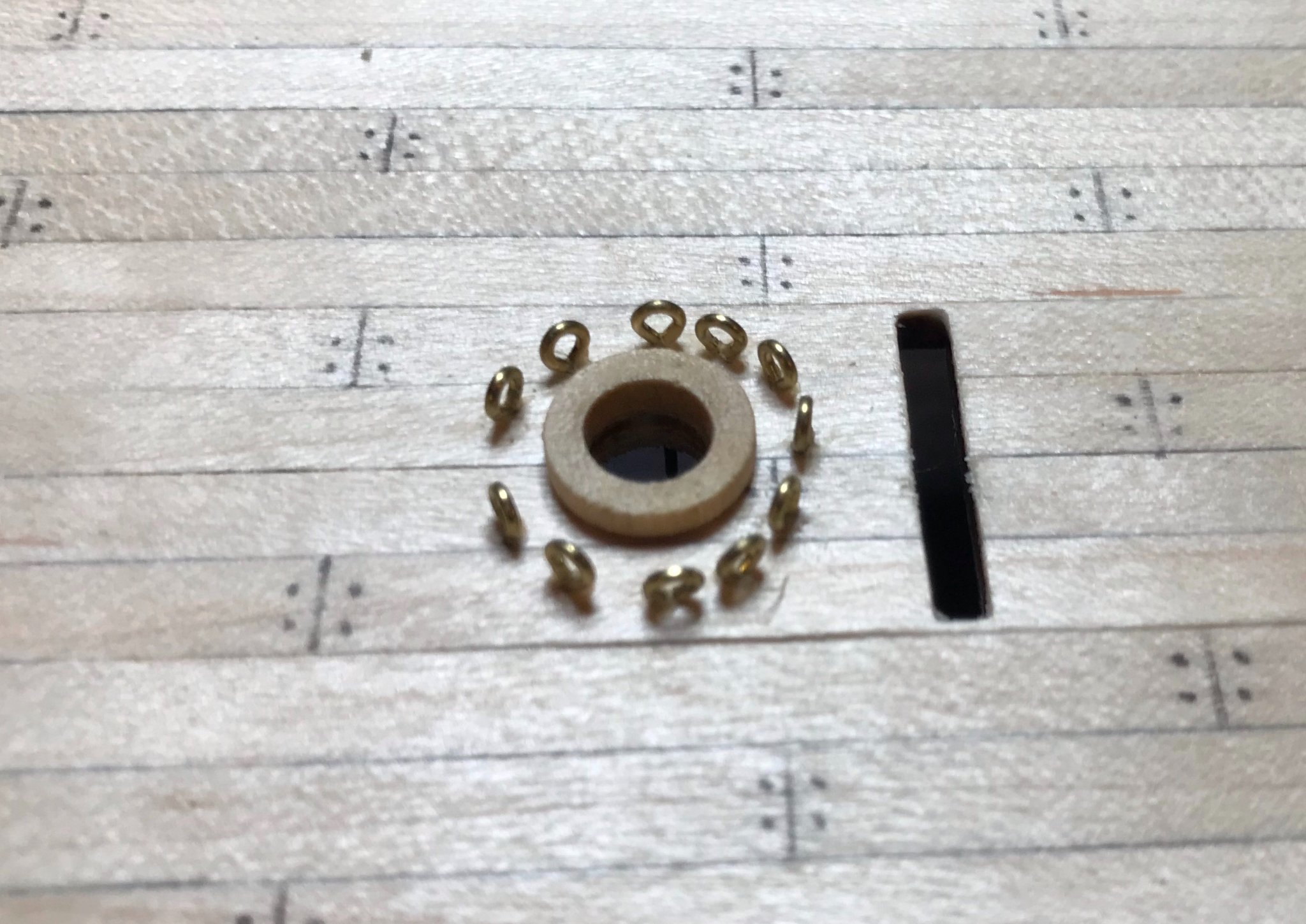
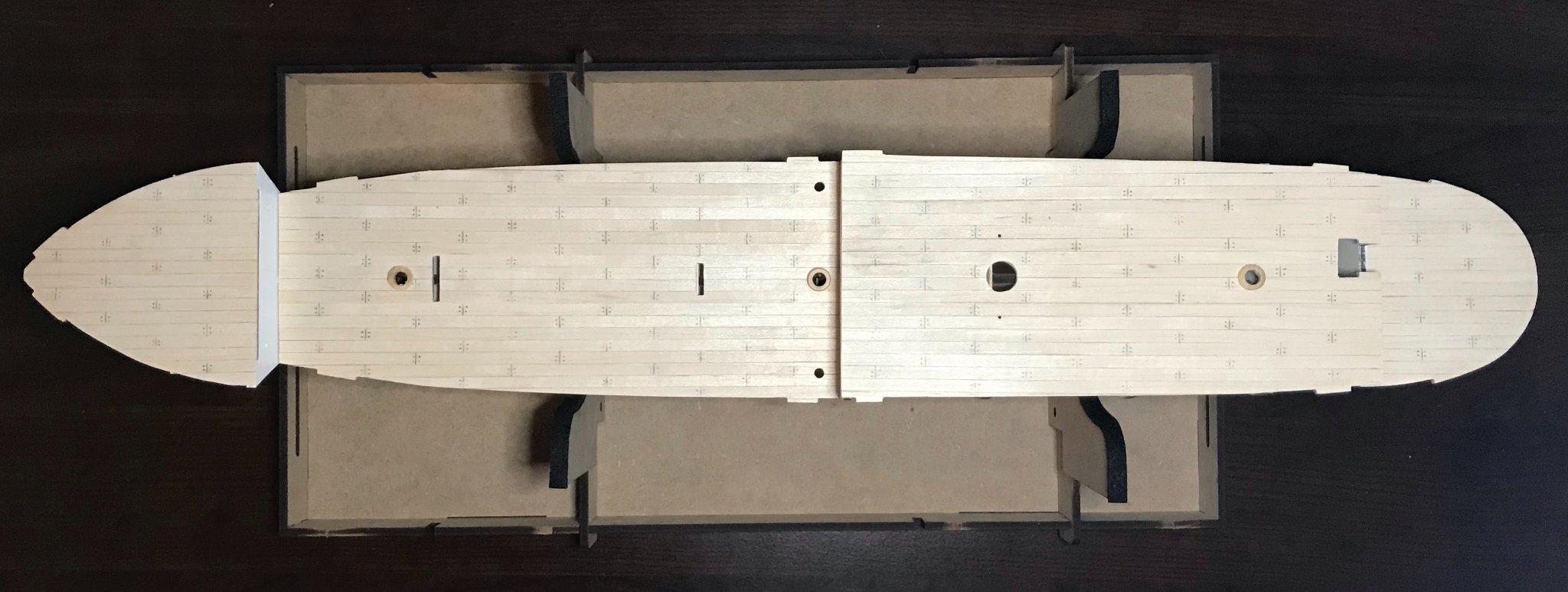
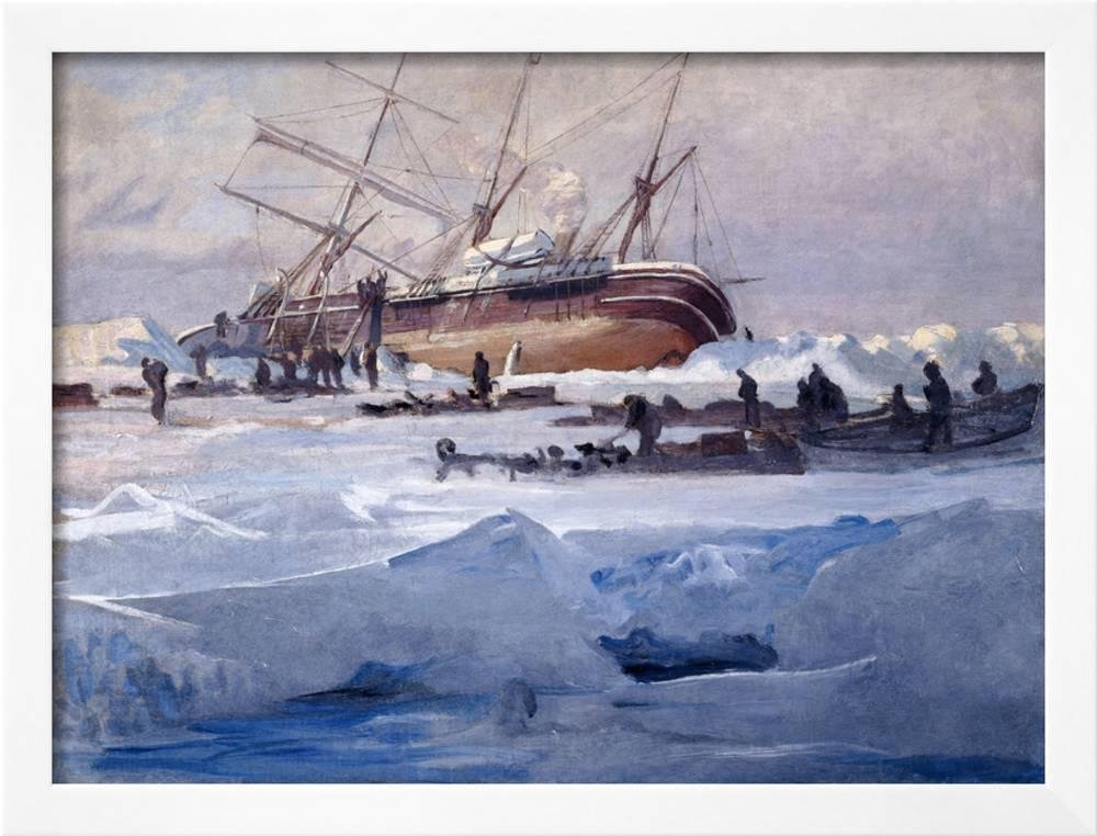
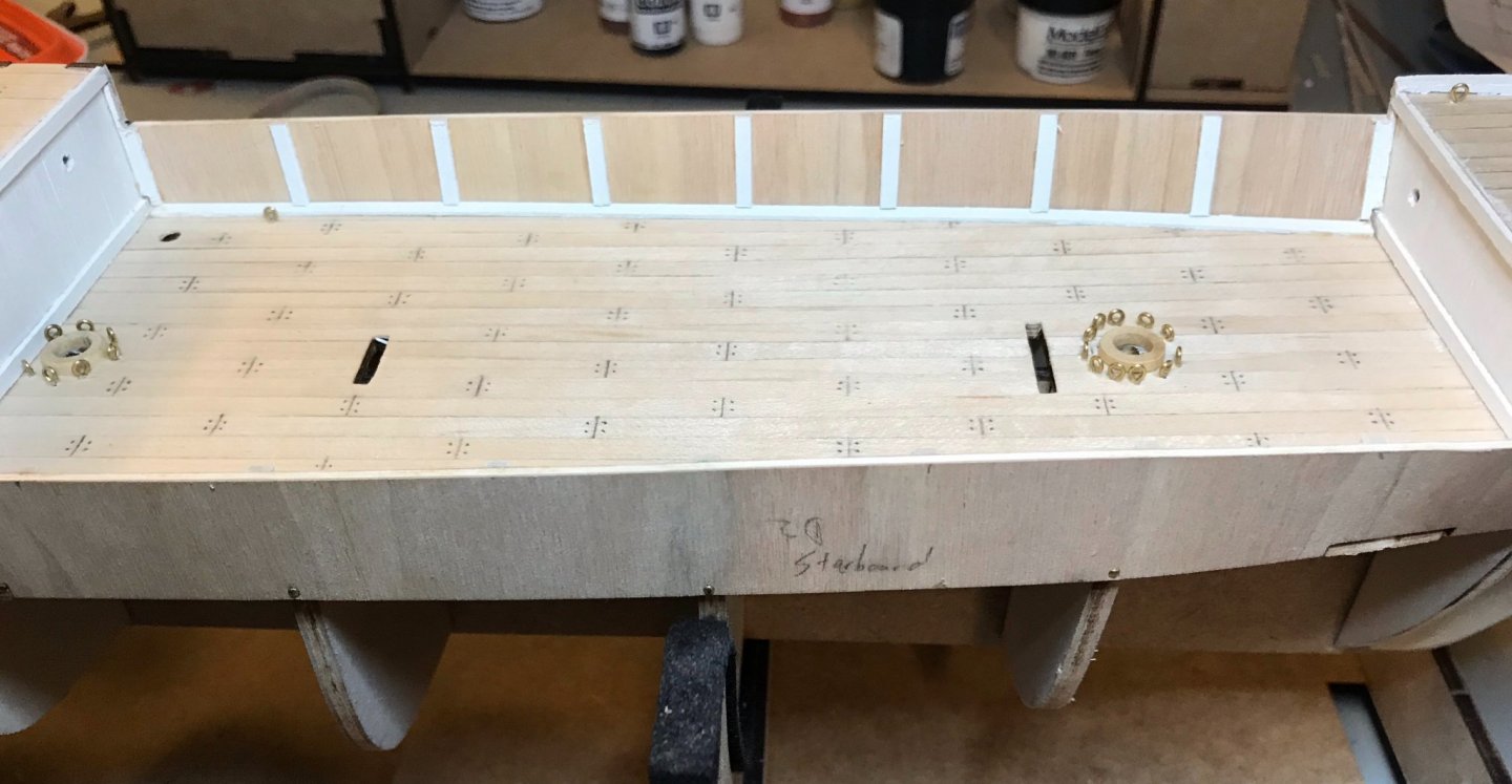
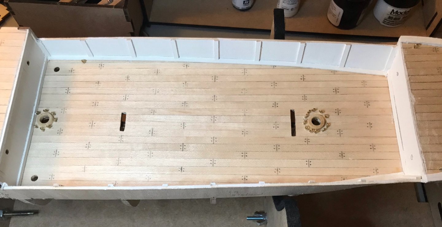
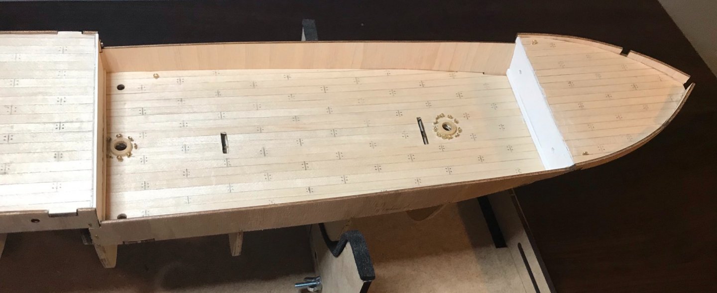
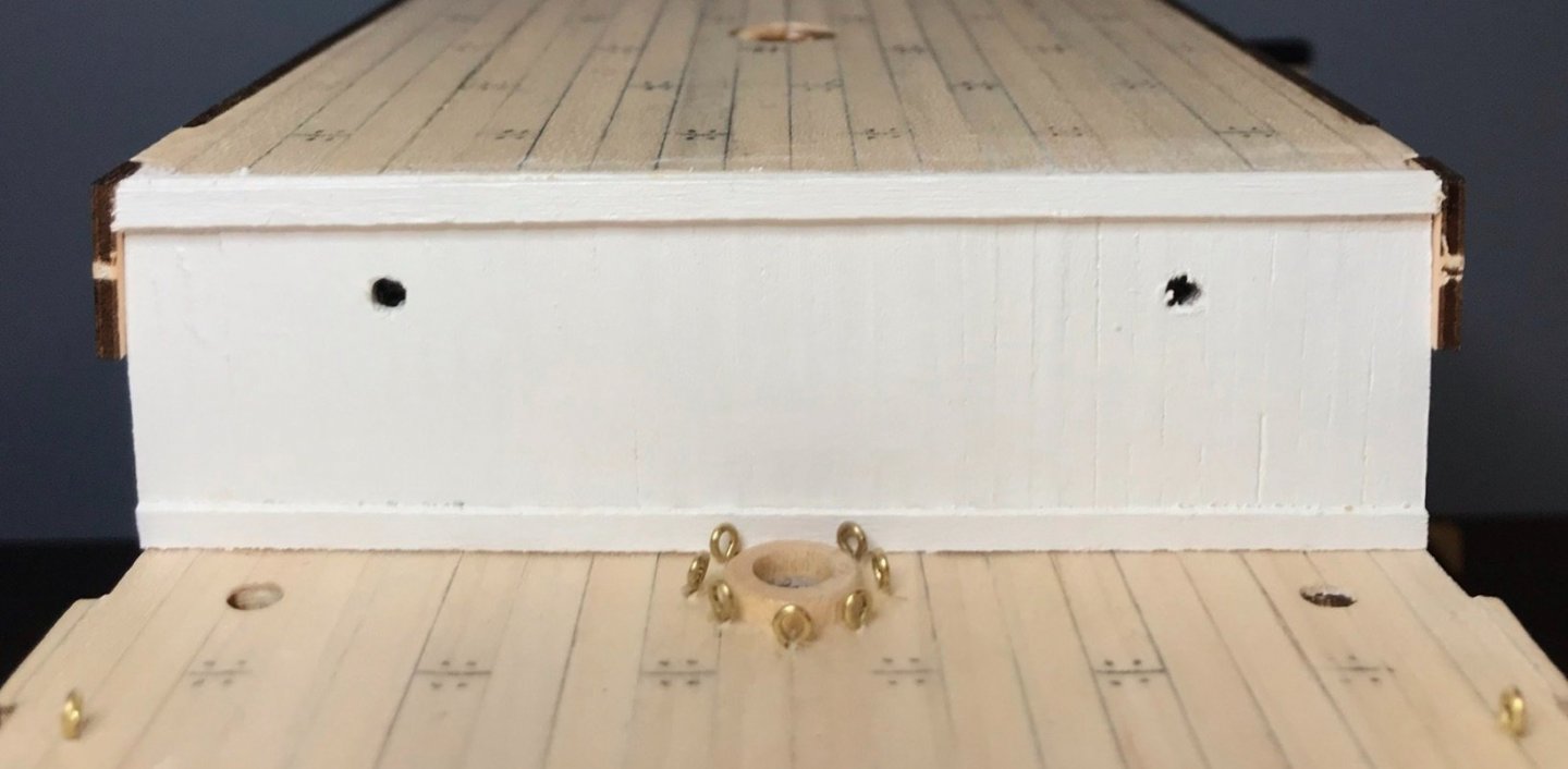
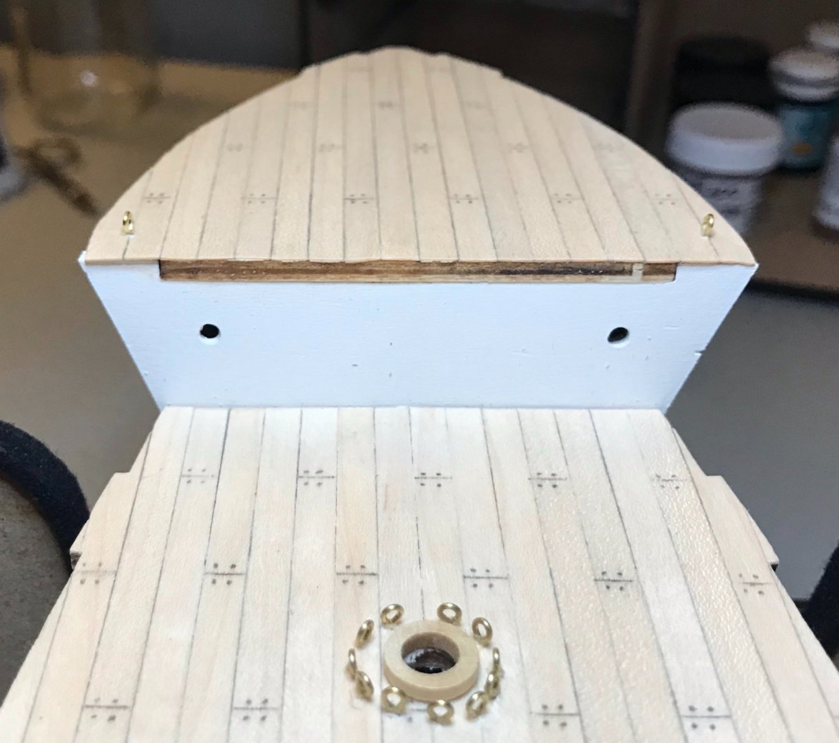
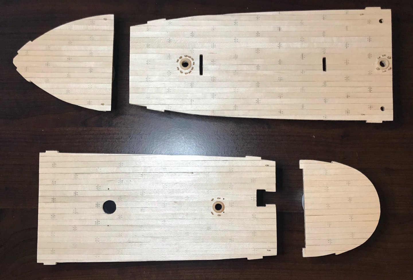
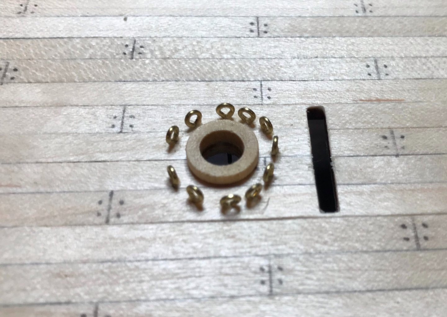
Thanks, Johnny. Glad to hear you'll be building an Endurance, too—I look forward to seeing your adaptations of OcCre's design! As a quick note, I was taking a closer look at the blocks tonight and concur with Chris Coyle's review. They're average fittings. Even though this is only my fifth ship, I've seen both better and (much) worse. I'm going to forge ahead with the blocks and deadeyes in the kit, but a more experienced builder like you may want to replace them. Also worth noting that the plywood is really lightweight...so light I suspect that at least the outer layers are balsa (I'm no expert in these matters, so may be way off on that identification). Those pieces seem sturdy enough, just very light. In other research, anyone building this should hunt for George Marston's paintings of the expedition; here's a sample of them at art.com, if you want some cheap print reproductions. Marston was one of the artists brought along to document the journey and his paintings are very striking. The painting entitled "The Endurance Crushed in the Ice of the Weddell Sea, October 1915" is the best view that I've found so far of the hull below the waterline. My conclusion (guess) that the ship had antifouling "brown stuff" comes from this image. Note that the ship is painted in full sunlight, so the black of the hull appears lighter than in other images, from which I assume that the antifouling paint also appears lighter than it really was. I've also discovered that the University of Missouri (M-I-Z! Z-O-U!) has a nice LibGuide on Shackleton's expedition; even though it seems to be a student project, there are some helpful resources, including a great gallery of photos, a link to the deck plans, and recommended books and films. A small progress update: I have installed almost all of the eyebolts on the decks and have put some satin finish on them. The first photo shows the decks laid side-by-side (top row: fore and main, bottom row: aft and poop). In the detail of the foremast, you can see the mast partner (at least, I think that's what the round wooden piece is called) and the eyebolts installed around it. The plans call for the eyebolts to all be parallel to each other, running fore-to-aft. But that looked really strange to me, so I turned them all to be parallel to the mast partner, making a more pleasing circle around the mast. Hopefully, I still feel good about this decision once I'm attaching the rigging to them! The eyebolts that I've attached so far will all be bent under the deck, per Johnny's suggestion. The remaining eyebolts need to be driven into frames under the deck, so I won't add those until the decks are installed.
-
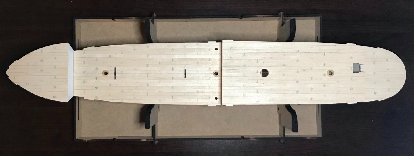
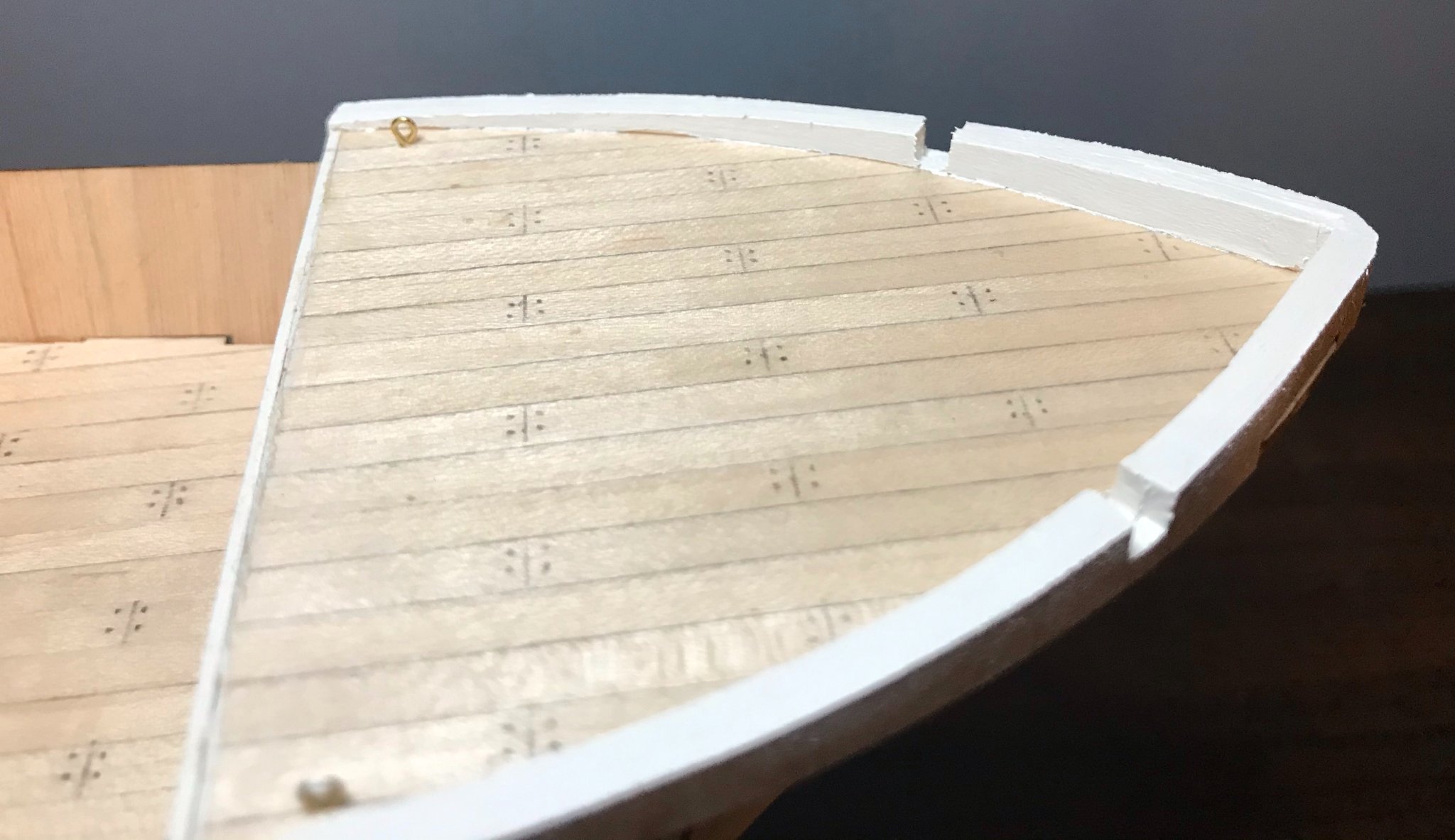
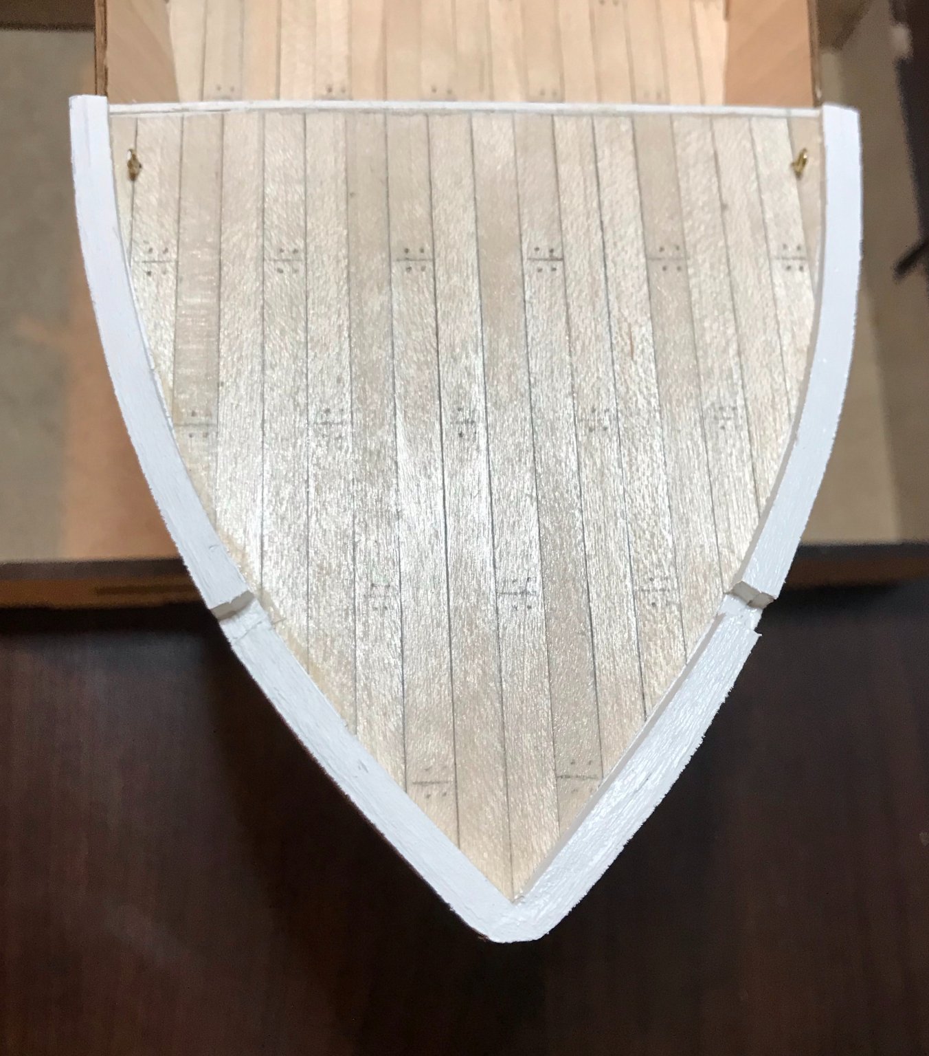
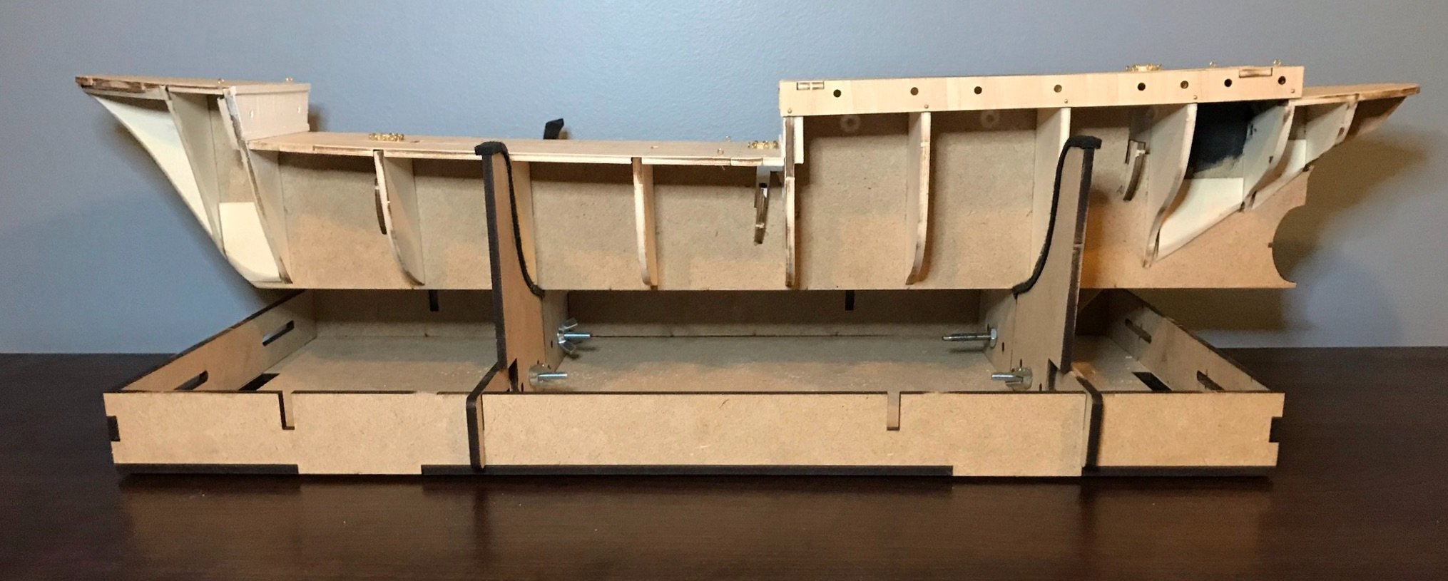
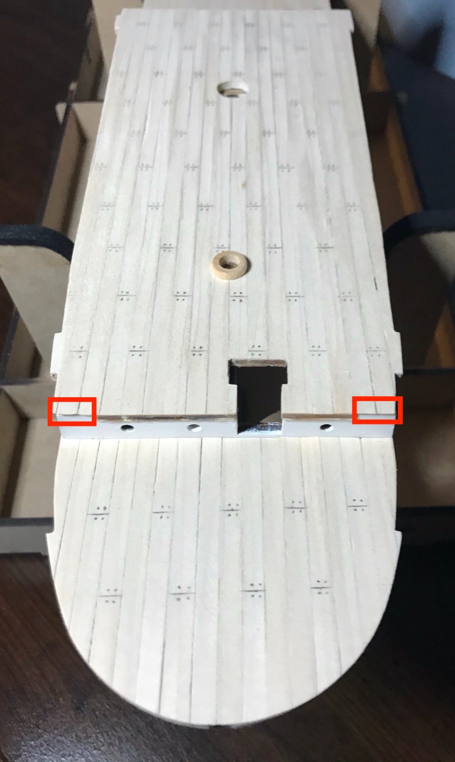
First a correction to my dumb math error in the previous post. At this scale, 5mm-wide planks represent 35cm-wide planks. Missed that easy math problem by an order of magnitude. A little bit of progress over the weekend, chipping away at the "B" steps. First up, I finished painting the portions of the frames that will be visible once the decks are installed and the hull is planked. Then, planking the other three decks. As far as the overall impression goes, I'm reasonably satisfied. A careful eye will note that the planking wasn't perfectly centered (especially on the poopdeck) and so the edges are not quite symmetrically planked. In terms of developing my skills, I'm pleased with how straight the planks are laying; the planks on the fore-, main-, and aftdecks even line up really well with each other! I managed to keep the edges pretty clean (though I'm glad that the bulwarks will cover up the one tiny corner that chipped off while I was sanding). And I like the degree of realism added by marking the lines and dots for the ends of boards. At this point, I just need to apply finish and (following Johnny's advice above) attach the eyebolts, then I should be able to glue them into place. However, things didn't go perfectly smoothly. I made a boneheaded mistake on the aftdeck and had to fix it. Unlike some kits (including the xebec I recently finished), the frames on this kit do not go above the deck, since the bulwarks are pre-cut plywood pieces that fit onto tabs on the decks. Instead, the subdeck has cutouts for all of the frames. When you plank the deck, the instructions have you lay the planks over those cutouts—which works beautifully, since OcCre has cut the plywood pieces so precisely. But as I lopped the excess off of the planks, I followed the shape of the corners, forgetting that the planking needed to extend over a cutout in each corner. I considered just adding some short bits of planking on top of the frames, but wasn't happy with that solution. Maybe none of my family or friends would notice...but I would know. So, I pulled the outer four planks off on each side. After some clean-up work, I Iaid new planks. There are two spots of damage remaining from the operation, but those will ultimately be covered by the dog kennels. (The spot on the port side is more visible in this photo than the one on the starboard side.) The red rectangles show two of the corners where those overzealous cuts were made the first time. For those doing this kit, this is an easy mistake to make, so please keep it in mind. Next steps: After finishing the decks, all that remains of the "B" steps will be to add a few more blocks to the bow and sides to aid in planking the hull.