HOLIDAY DONATION DRIVE - SUPPORT MSW - DO YOUR PART TO KEEP THIS GREAT FORUM GOING! (Only 36 donations so far out of 49,000 members - C'mon guys!)
×

Ed Ku20
-
Posts
230 -
Joined
-
Last visited
Content Type
Profiles
Forums
Gallery
Events
Everything posted by Ed Ku20
-
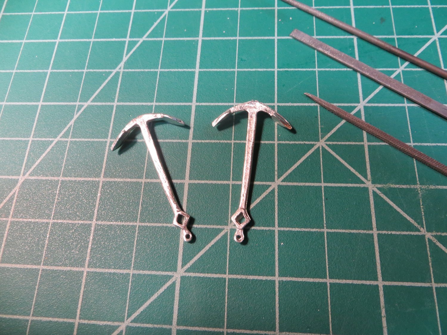
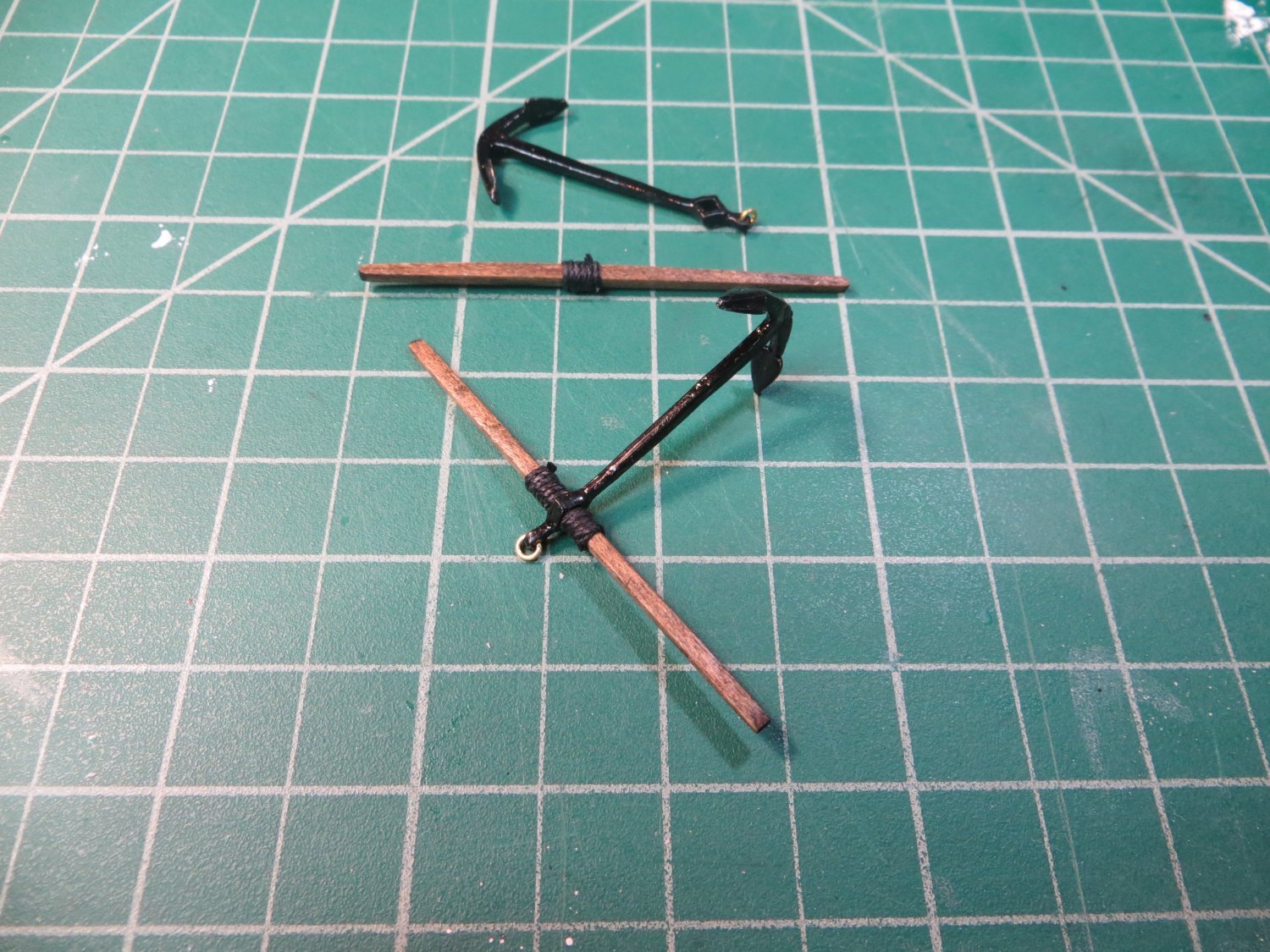
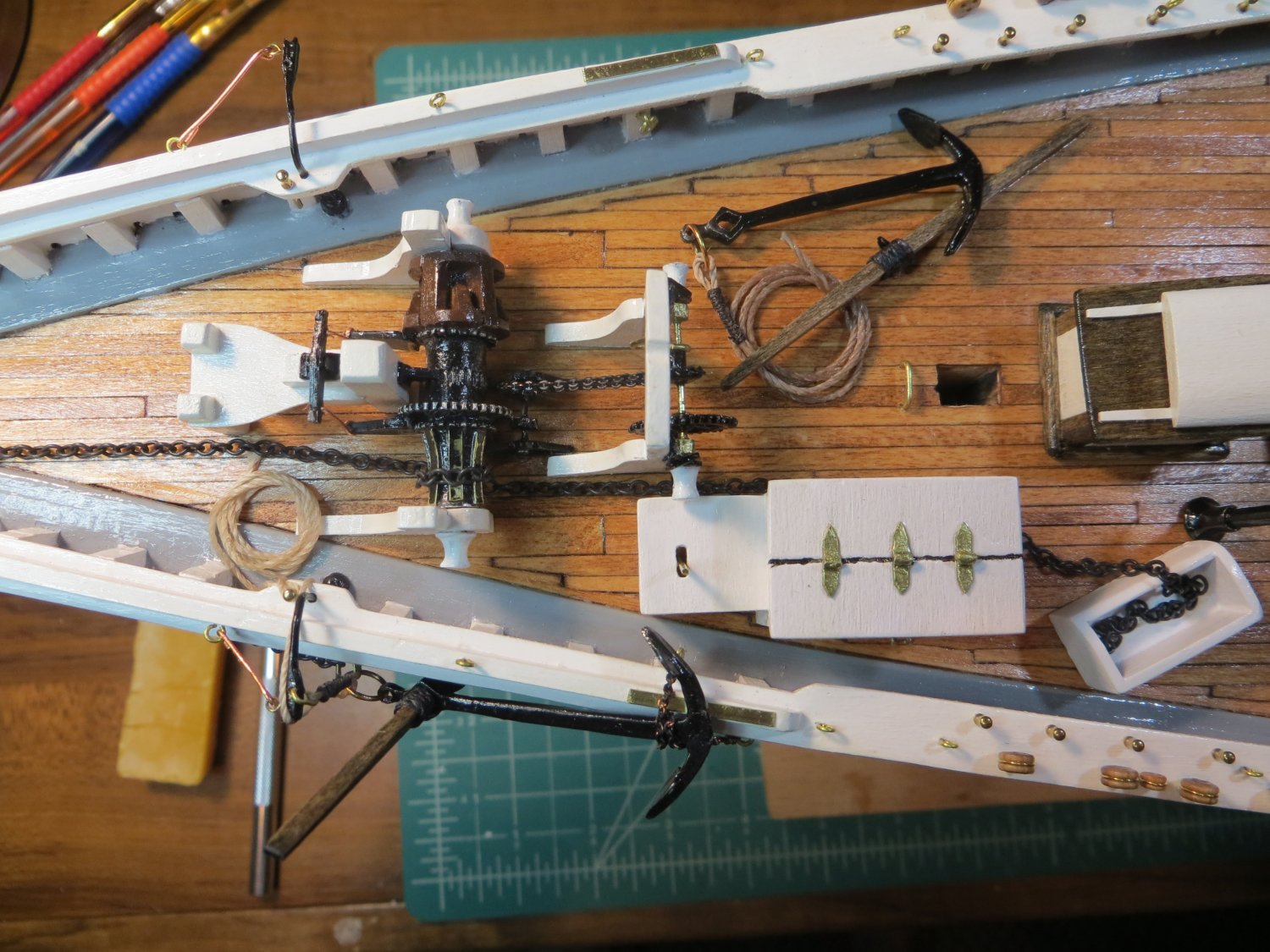
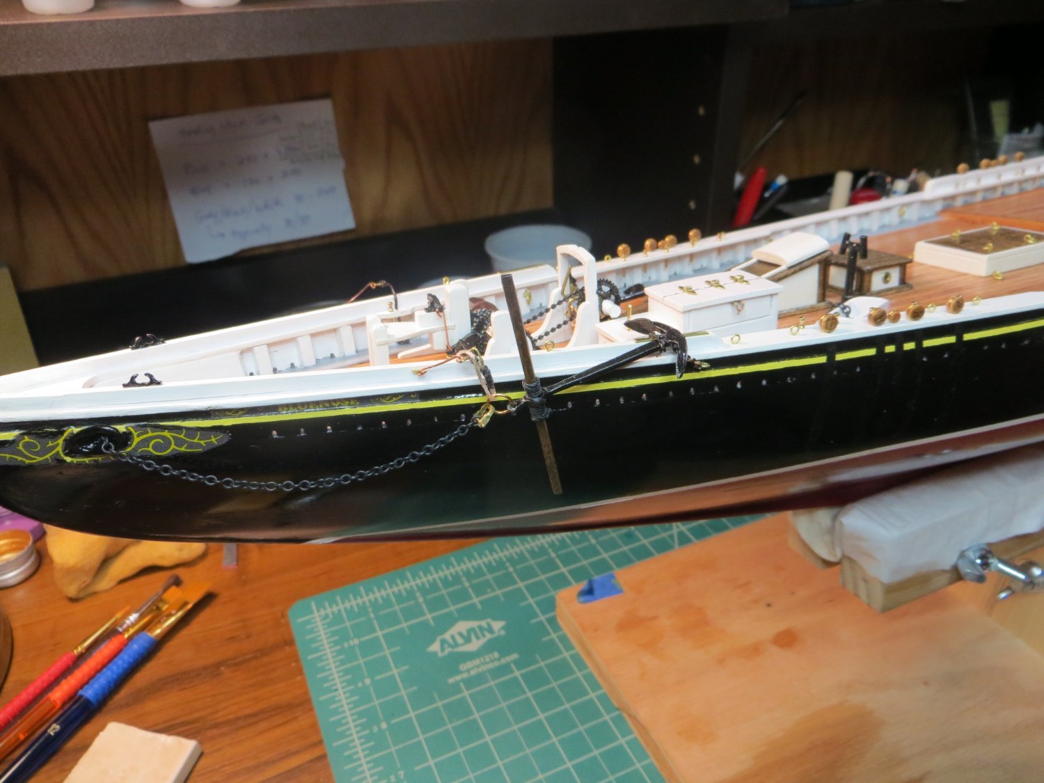
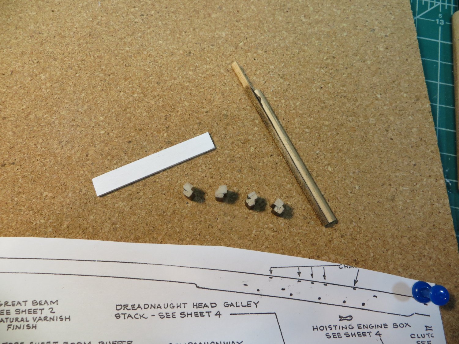
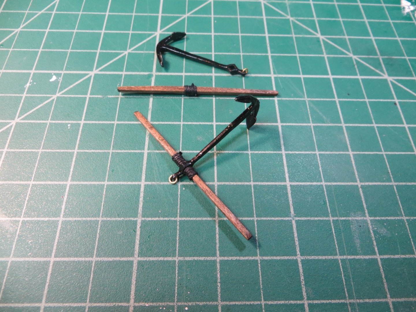
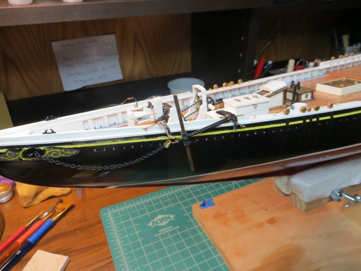
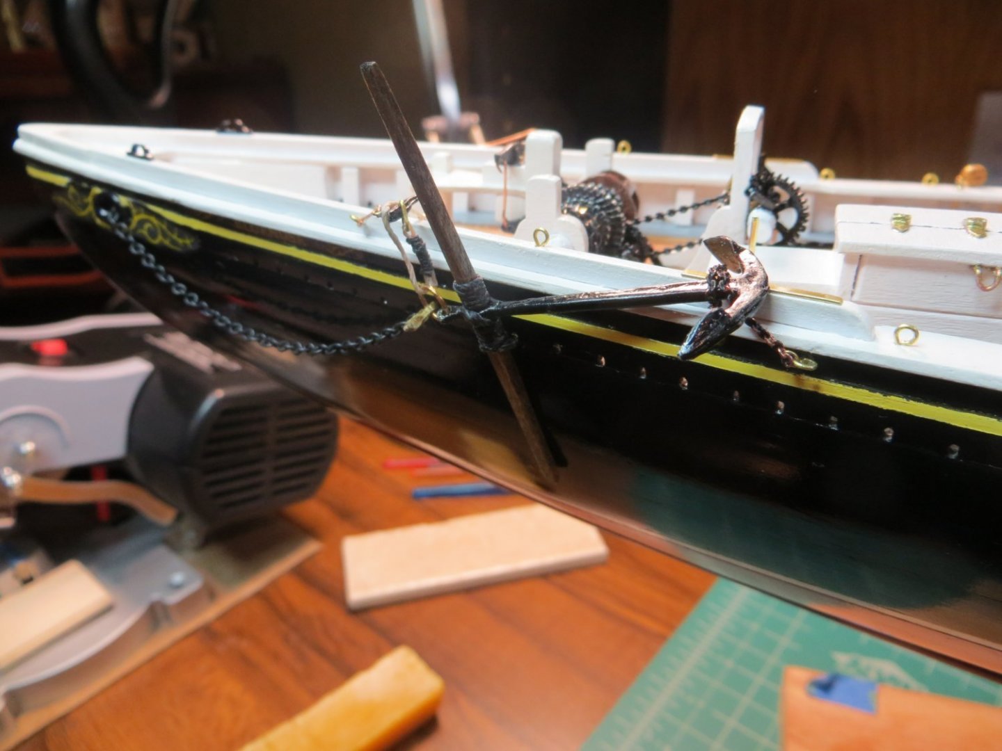
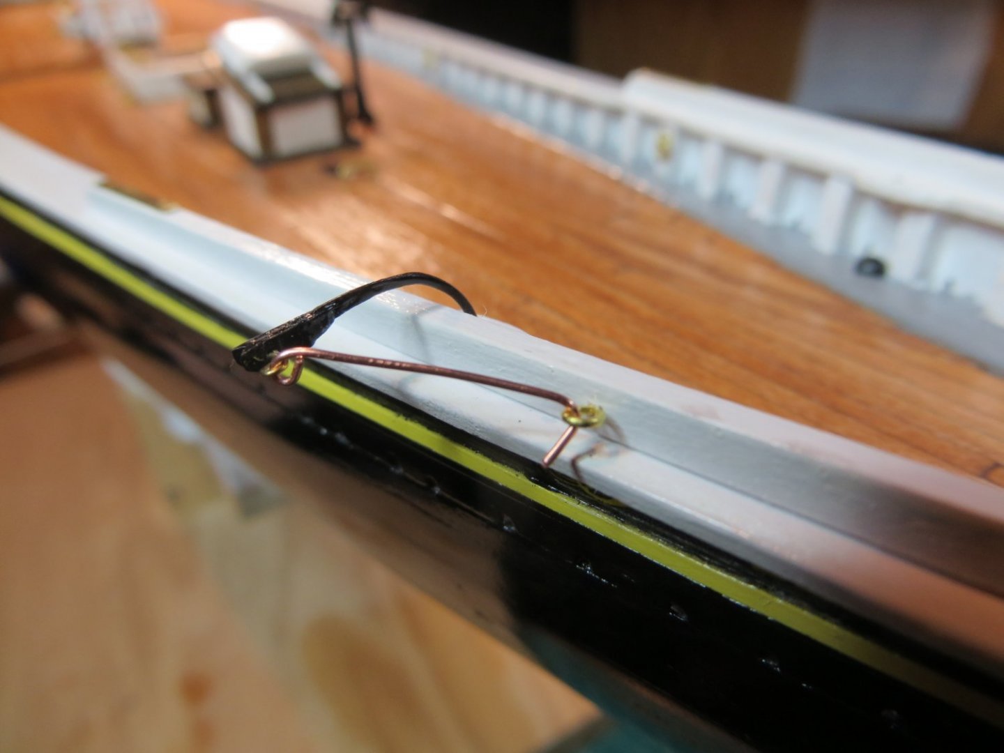
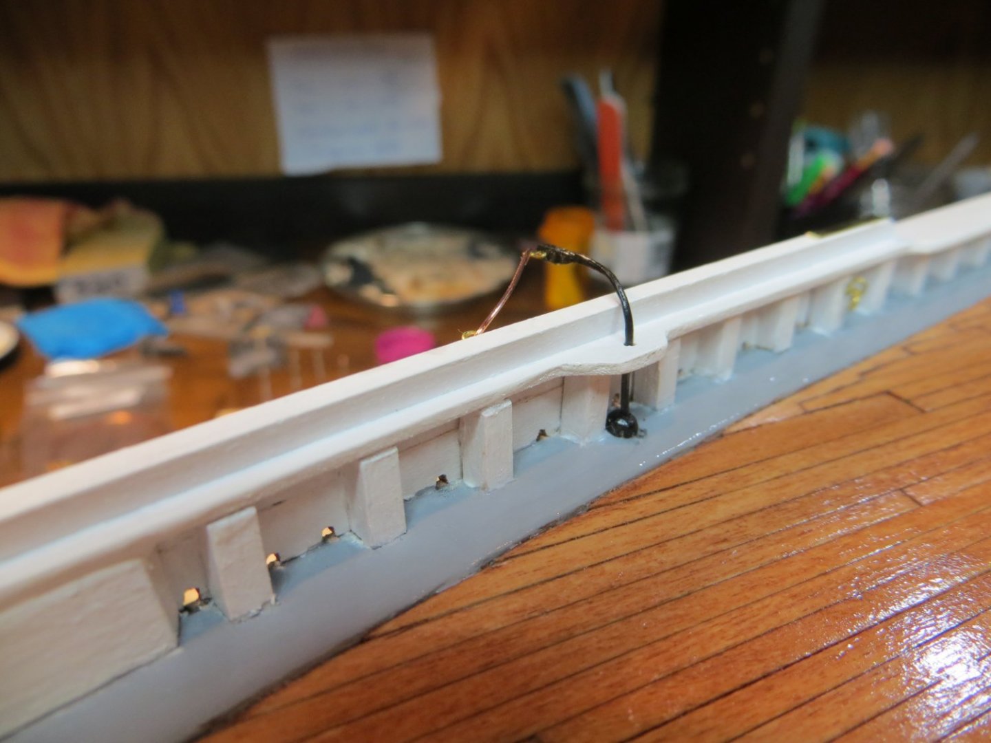
 Originally posted July 16, 2021 [Knowing what I know now, I should have waited to install the hanging anchor & cathead until later in the build. It has been an obstacle to everything done on the ship! I keep bumping into the catheads and bending them down against the hull. I stopped bending them back because I was afraid they may break off. I will readjust everything when the ship is done.] Anchors There are 3 steps for completing the anchors. a.) Build the anchors b.) Install the catheads that I built earlier c.) Add the rings, eyebolts, chains, ropes, etc. In preparation for this step and future steps that require seizing rope and serving rope for shrouds, I purchased Chuck Passaro’s Serv-O-Matic machine from Syren Ship Model Company. This is a nice solid rig that is made from cherry boards. It is designed for serving, but I was easily able to follow Chuck’s instructions on this website to rig it for seizing rope and making eye splices. You can find this info here: https://modelshipworld.com/topic/16988-modifyingjigs-for-the-syren-serv-o-matic/?tab=comments#comment-524633 Construction Steps Building the Anchors 1. I filed and cleaned the two cast metal anchors in the usual manner. I painted them with Testor’s black enamel. 2. Make the wooden bars from 3/32” square strip wood. Measure the length (2-18/32”) from the plans and mark the center where the wood will sit in the anchor hole. The hole is shaped so that one corner of the wood is at the top and the other is at the bottom. 3. Draw a line from the center point to the outside edge. Sand down the extra wood. Shape the rest of the bar to fit into the hole in the anchor. 4. I stained both wood bars with my dark walnut, after sanding sealer was applied and allowed to dry. 5. Slide a bar into one of the anchors. Wrap some thinner black rope around the bar on either side of the anchor hole. Attach a brass ring to the top. The standard ring supplied by the kit is too small for this. So, I wrapped some 0.025” (22 gauge) brass wire a bunch of times around the end of a drill bit that had the size I wanted. I slipped it off the bit & snipped it down the middle with wire cutters to make a bunch of larger size split rings. I attached one to both anchors. 6. For the other anchor I wrapped the rope around the bar and added the ring, but do not slide the bar into the anchor. Only one anchor is used to hang on the railing. The other is stowed on the deck without the bar. Catheads 1. I used CA glue to attach both catheads into the small bases that I made earlier. See my post on the miscellaneous items on the Fore Deck for more details. 2. I made an oval shaped ring from some brass wire and attached it to the second hole in the cathead. I seized a shank of tan rope to be used for hanging the anchor. Rigging the Anchors 1. The Starboard side uses the unassembled anchor. Install the cathead with a little CA glue and connect the copper stay bar. 2. I then used my new Serv-O-Matic to seize a piece of tan rope using thin black thread. This was slipped into the ring on the anchor with enough extra rope left for coiling on the deck. 3. I glued rope to the deck with some CA glue and then glued the bar on top of the coil and finally the anchor. 4. For the hanging anchor I looked at a lot of pictures on the internet and also various blogs to figure out how to attach the anchor to the cathead. I’ve never seen so many different methods to do something on this ship! So, for what it’s worth, here is what I did. a. I attached a shackle to the ring on the anchor. Making the shackle was a project in itself. I tried several methods recommended by others, which all failed to work for me. Finally, I drilled holes in the ends of an 8mm length of 1/64 x 1/16” brass strip that came with the kit. I used my pin vise for this (but later used my drill press to make these holes). I rounded off the ends where the holes were drilled. Then I bent the strip in the shape of a “U” and filed down the width at the bottom of the U. I purchased some really tiny bolts and nuts from a hobby place called ModelMotorcars.com to complete my shackle. b. I connected the original chain that I bought for the winch, that was too big, to the shackle and inserted the bolt. I used a drop of CA to make sure it stayed shut and cut off the end of the bolt. I draped the chain over the railing until I was ready for it. 5. I now turned to the chain that holds the anchor to the anchor pad on the rail. I attached an eyebolt in the proper position outside the rail. I had some trouble connecting the chain to the eyebolt on the stanchion. It ended up coming out of the hole, which was a good thing! I slipped the last link of the chain through the eyebolt and reglued it back into the stanchion. I wrapped the chain around the anchor a time and a half and slipped that link into the eyebolt outside the rail. 6. Now I was ready to run the chain through the hawse pipe hole. This proved to be difficult as it was a tight fit. I had to tie some thread to the end of the chain and work it through the pipe and then finagle the chain through. I wrapped it around the brass side of the windlass and then ran it to the chain box. I think I’m going to need to purchase some more chain to fill the chain box. 7. To complete the rigging, I attached the seized end of the tan rope through the oval ring on the cathead. I ran it through the ring on the anchor and back over the top of the cathead and tied it off on the belaying pin next to the cathead hole. I coiled the end of the rope up and glued it to the deck. 8. Finally, I made sure all the chains and ropes were tightened properly and attached well. I had to use some CA glue to stiffen the tan rope so the “hang” on the anchor looked realistic.

- 96 replies
-
- 2
-

-
- model shipways
- bluenose
- (and 1 more)
-
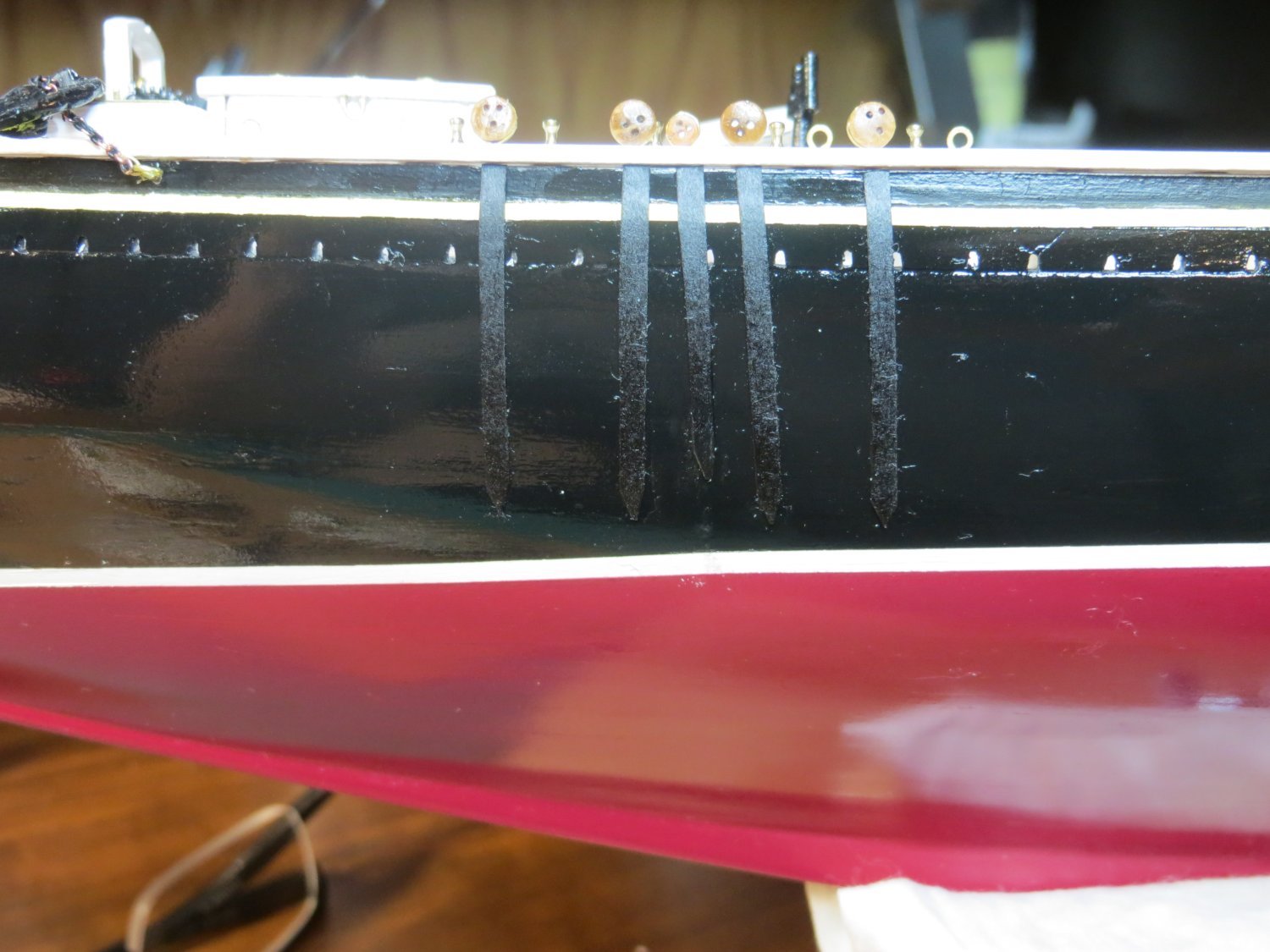
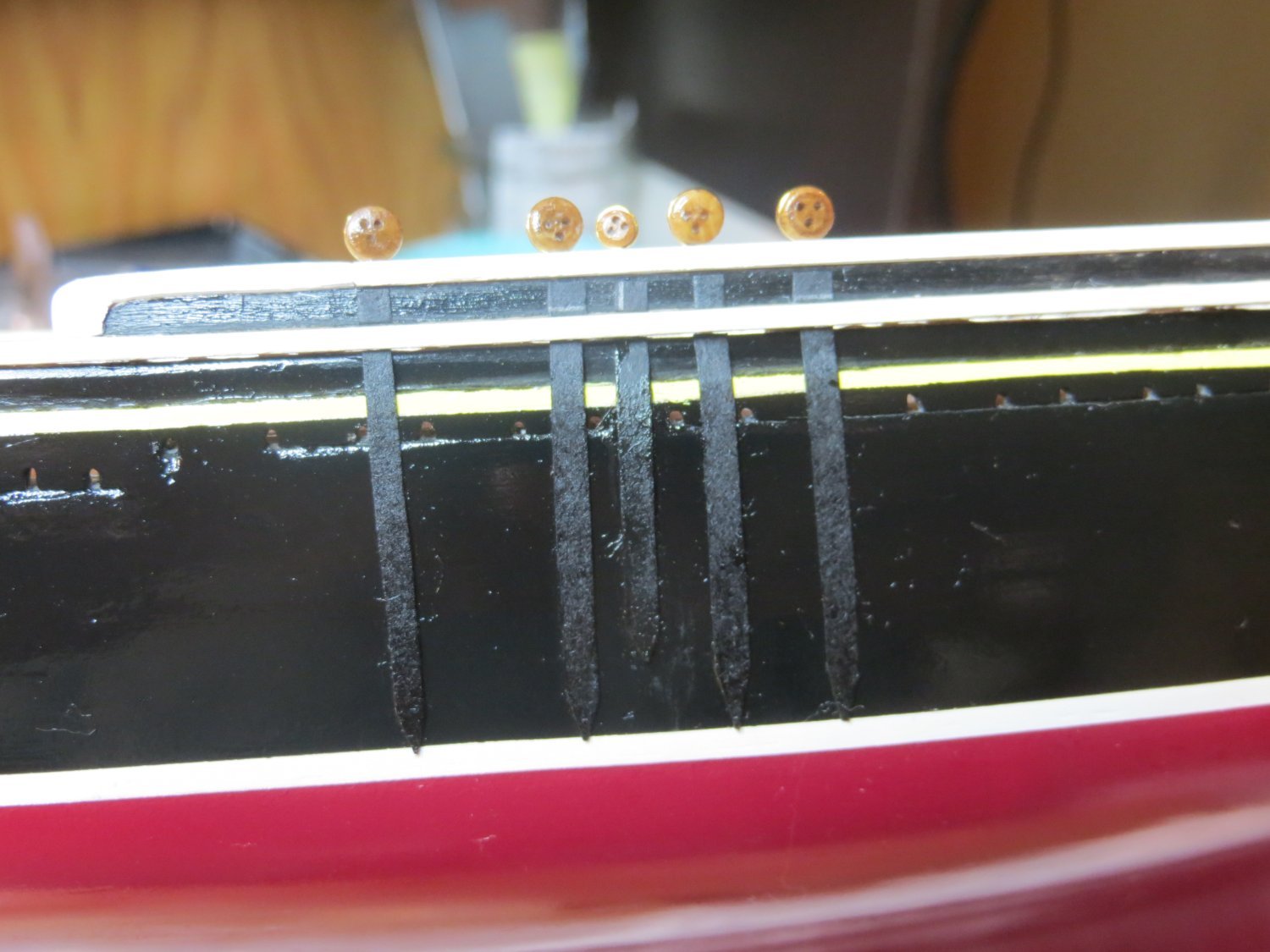
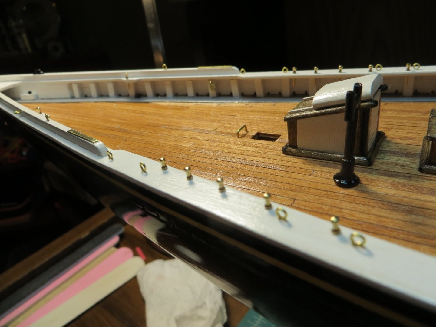
Originally posted July 14, 2021 Deadeyes & Chainplates The next step in my build plan is the deadeyes and chainplates. If you’ve been following my build log, you may recall that my railing on the port side slipped slightly inboard while the glue was drying because I used rubber bands to hold them down. Since my main railing doesn’t have the required overhang on this one side, I am going to use 1/64th inch thick black cover card stock that I ordered on-line to simulate the chainplates instead of using brass strip. I’ve seen others do this in my research. There are 2 sizes for the chain plates that are attached to the side of the hull. The smaller size is for the top mast shrouds, while the rest are for the lower masts. On my next build I hope I can do a better job with this. Construction Steps 1. I made a template of the required sizes (according to the plans) and used these to outline the card stock for cutting. They need to be 1/64” thick, which is the same size as the brass sheet that should have been used. They are 1/16” wide and have a point at the bottom. I cut them out using some really old dissecting scissors from a biology lab class in college. I sharpened them up using a wet stone to get a really clean cut. The cut pieces were set aside in a plastic bag until needed. 2. There are 20 deadeyes required. 16 large and 4 smaller sized ones. Check the plans for the right sizes. I think these are part # WP0339 for a 9/64” size deadeye and WP0390 for a 3/32” deadeye. I placed them on a piece of fine wire and dunked them in some Minwax Natural stain. I chose this after testing several colors, because I thought it looked good with the other stains on the ship. 3. After staining, wrap the deadeyes with the thinner 0.014” brass colored wire from the kit. Twist the wire at the bottom with pliers and cut them relatively short for gluing into holes that will be made along the railings. 4. I measured the placement of the holes on the railings for each deadeye off the plans. I marked the spot for each hole in pencil. I used my pin vise to drill the holes for a snug fit. Dip the end of the wire in the medium CA glue and insert in the holes. Make sure the deadeyes are parallel to the railing. 5. CA glue was used to glue the card stock chain plates under each deadeye. They are supposed to be angled according to the angle of the shroud that they serve, but I did not worry about this. Along the quarter deck a tiny square of cardboard had to be glued in the space between the monkey rails. 6. Unfortunately, I messed up the hull with CA glue and then made it worse using the Un-Glue!! Apparently, this stuff undoes paint and poly as well! After I was finished, I lightly sanded down these bad spots and touched them up with black paint. Finally, I reapplied some rub-on poly. I think the end result will not be noticeable to anyone but me. Chainplates for the Fore mast: Chainplates for the Main mast: The Deadeyes:


- 96 replies
-
- 3
-
-
- model shipways
- bluenose
- (and 1 more)
-
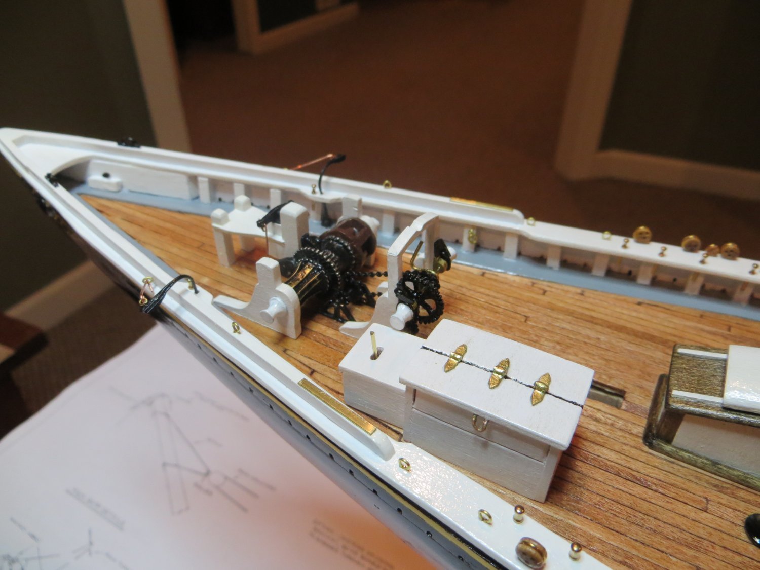
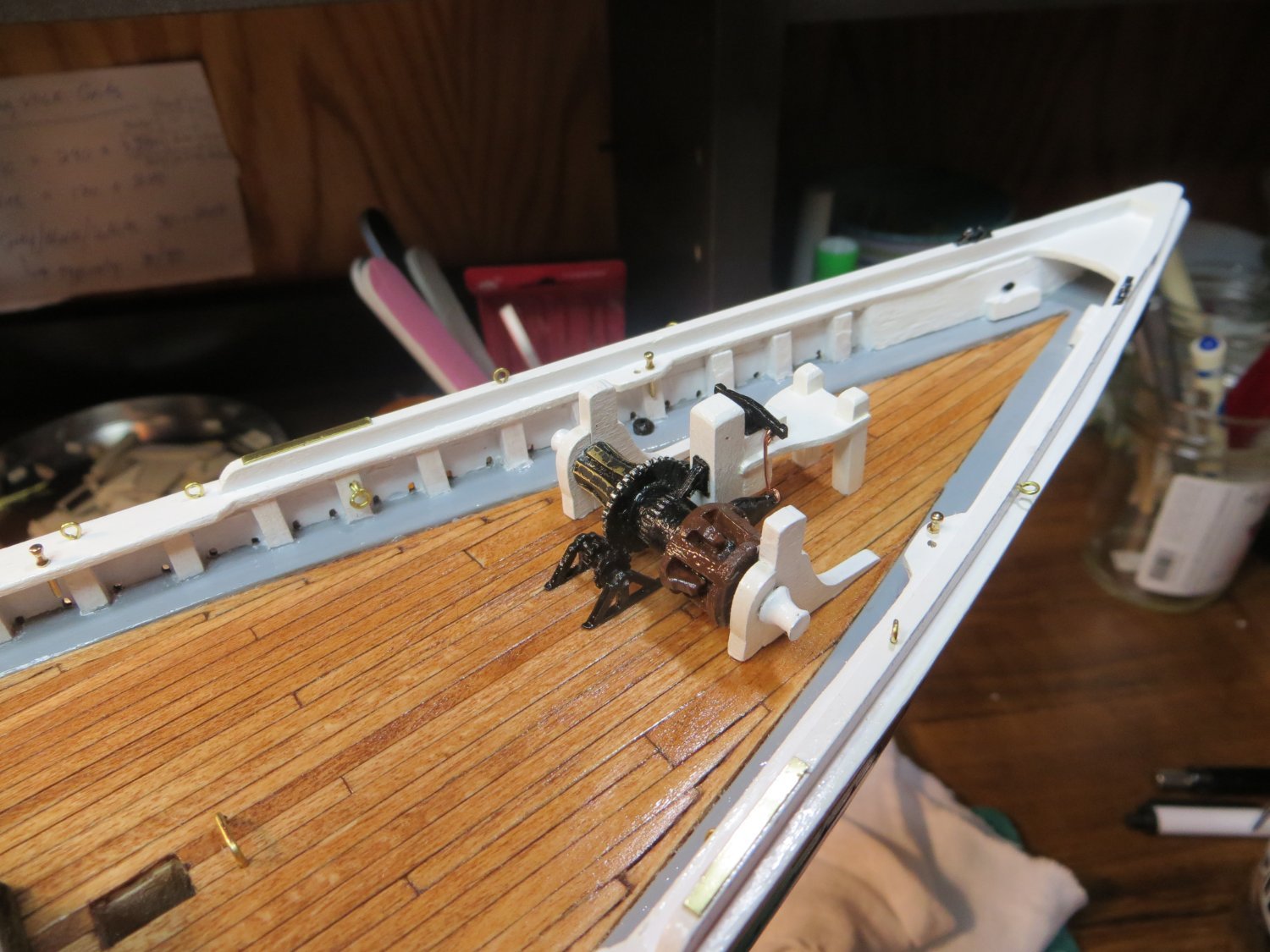
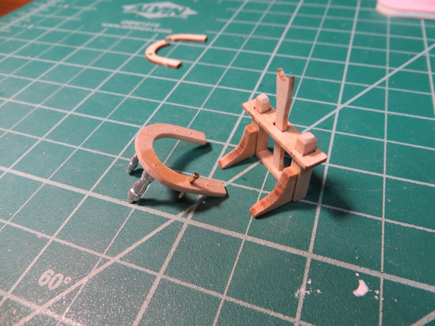
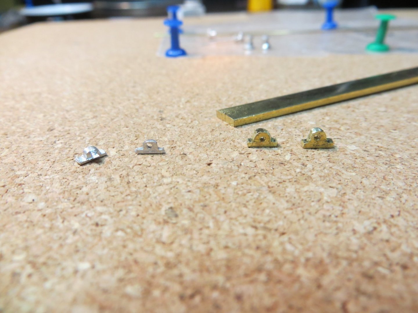
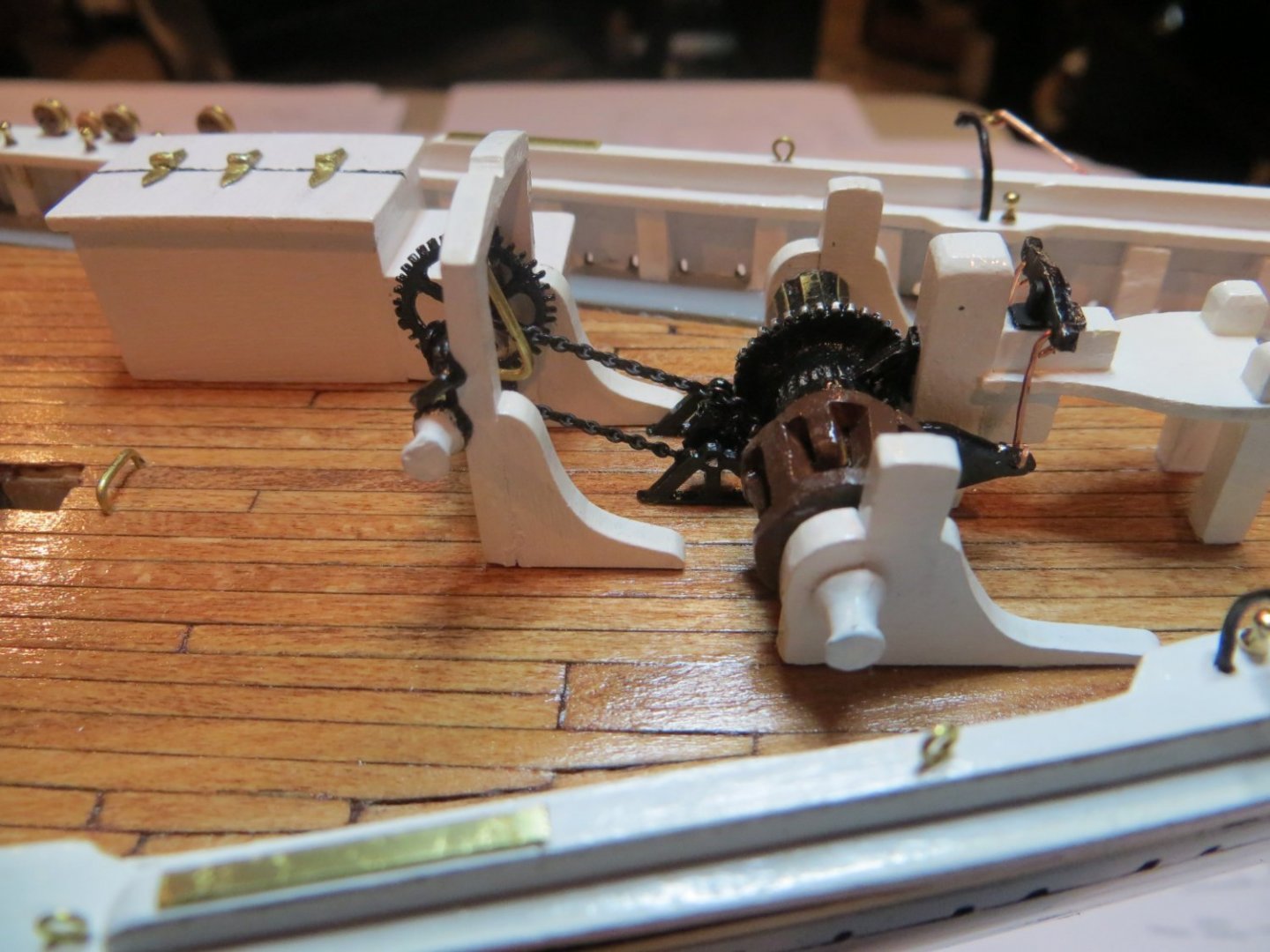
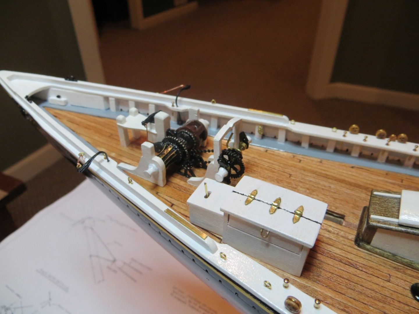
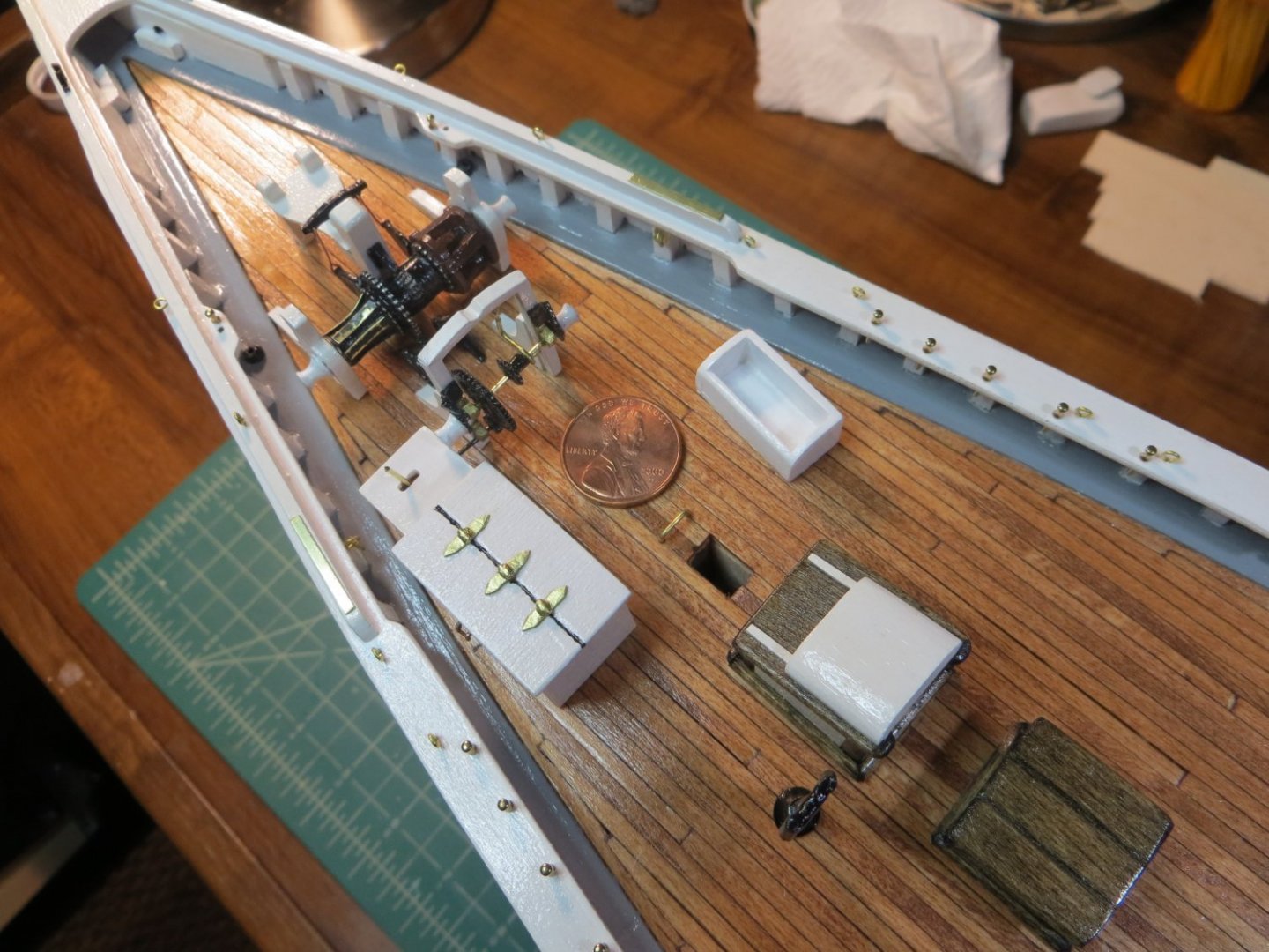
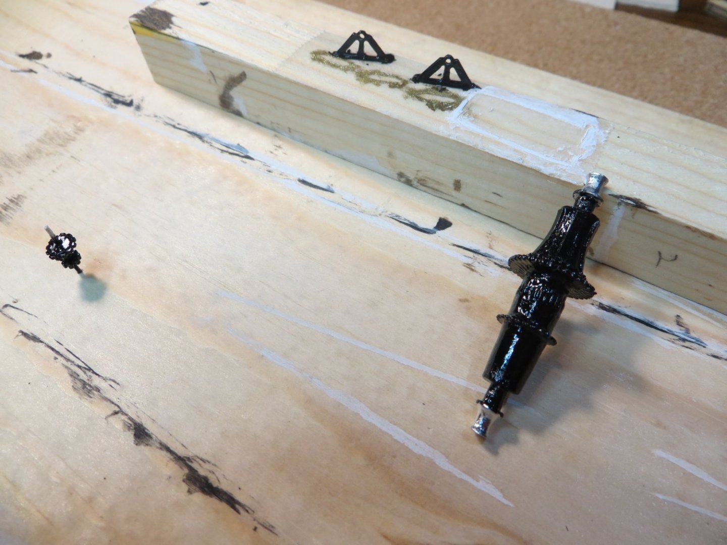
Originally posted July 14, 2021 Fore Deck Machinery Continued As promised here is the completion of the machinery on the fore deck. This centers around the Winch Machinery. There were two challenging steps for me. One was keeping the joint on the top of the jumbo jib boom crutch together while I worked on it. I ended up breaking one side and redoing it a couple of times. This piece is very fragile. The other was finding the right chain to connect the winch to the counter shaft assembly. I also ended up building my own winch gear shaft bearings because the ones from the Britannia metal were in such poor condition. Winch Machinery -- This connects the windlass and counter shaft to the engine box. These cast metal parts are mounted onto the jumbo jib crutch, which is built mostly from laser-cut pieces. Construction Steps 1. Remove the Jumbo Jib Boom Crutch parts from thick set E and carefully sand off the laser char 2. Cut posts that are the same size as the laser pieces. Glue the pieces together. I applied some extra CA glue to strengthen the joint at the top. But I still ended up breaking it and regluing and repainting it more than once. I painted this assembly white with a brush, by hand. So, be careful. 3. File, clean and paint the various metal parts. I cut the various parts off of the shaft. I had to drill holes in the gears to fit a 0.032” diameter brass rod. I painted all of these parts black except the winch bearings which I painted w/ the Testers brass enamel to help them stand out more. Shaft end caps were painted white w/ the same Vallejo acrylic paint as the stand. The shaft was painted black after it was slipped into the bearings and after the gears were glued on. 4. I ended up making my own winch bearings from a strip of 1/16” x 1/4” wide brass. You can see in the picture below the misshapen pieces that came from the kit, the brass strip I made them from and my finished bearings. To make these I drew their shape and size on the brass strip with the bottom being the machined straight edge on the outside of the strip. The top parts met in the middle. I next drilled holes wide enough to hold the gear shaft (#64 bit in my drill press). I did this before cutting the pieces out so I had the large brass strip available to hold down on my X-Y table while drilling. Then I used my jeweler’s saw to cut out the pieces. I shaped the curve at the top with pliers to hold them while using various files to get the final shape. 5. I created the control bar on the winch gears from the same .032 brass rod. Another piece was used for the engine box’s control bar. I left these unpainted to maintain the brass look I’ve used around the ship. 6. Glue the winch assembly to the deck. This must be positioned so the small winch and windlass gears line up. I used the plans to see how far away from the windlass to locate it. Carefully position the engine box so the slot in the side aligns with the gear shaft. 7. Attach black chain between the small winch gear and the small windlass gear. I had a hard time finding the right size chain. The first one was too big. (I will use this for the anchor) I ended up using copper chain that I spray painted black. It has 27 links per inch. I bought it from Model Expo.
- 96 replies
-
- 3
-
-
- model shipways
- bluenose
- (and 1 more)
-
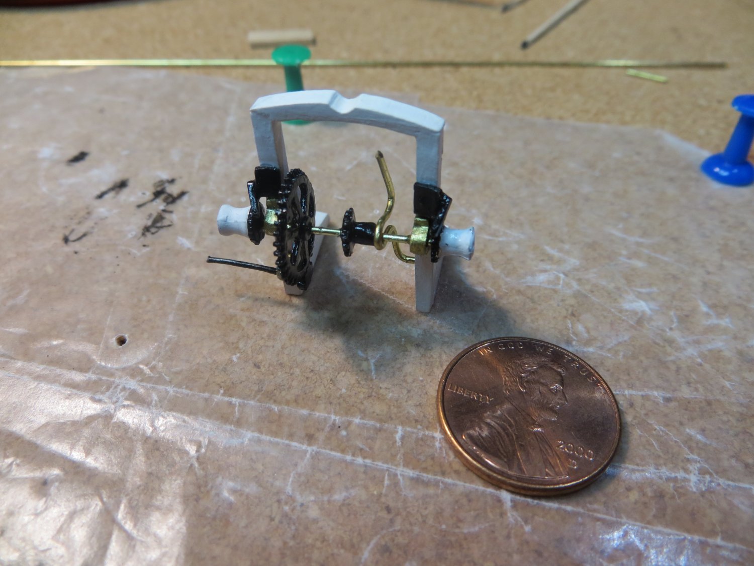
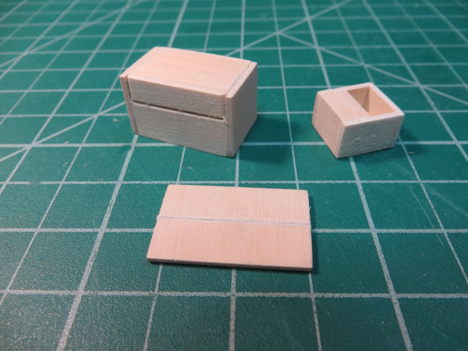
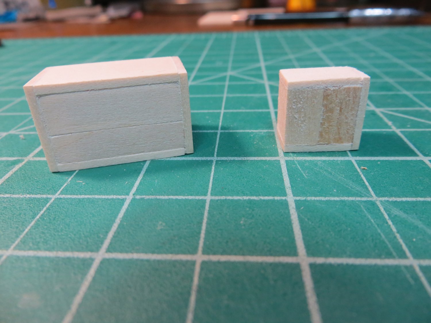
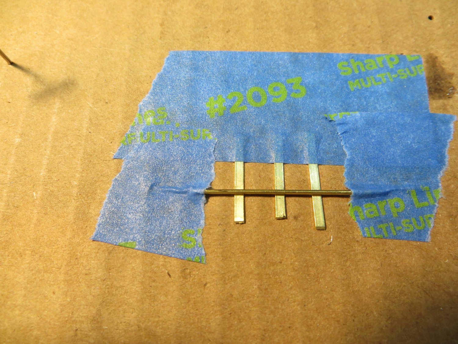
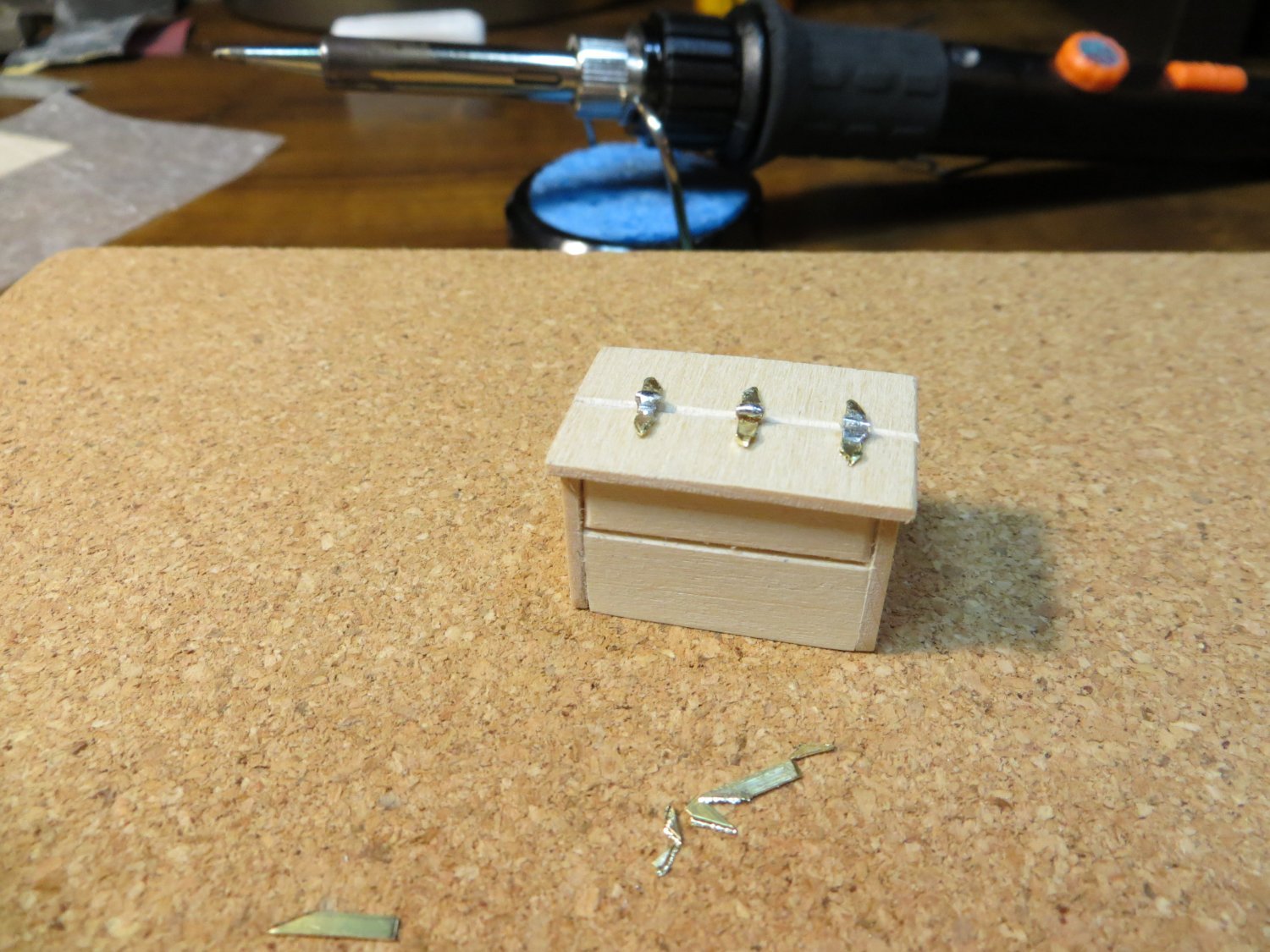
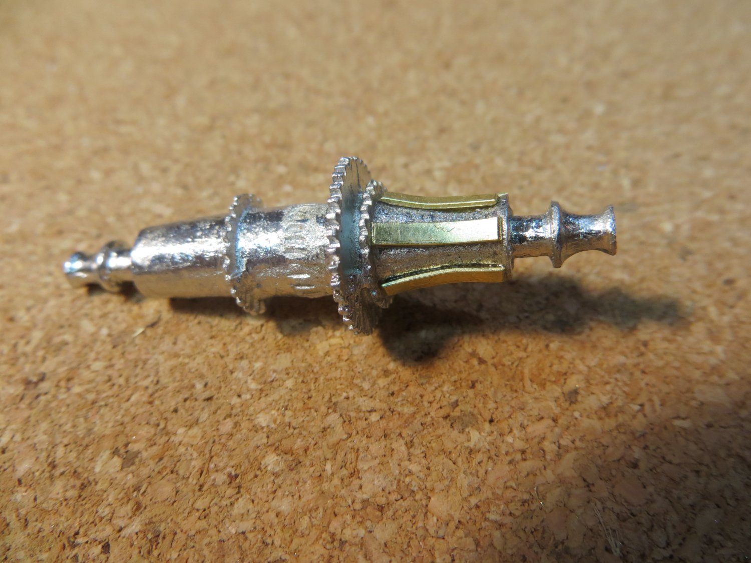
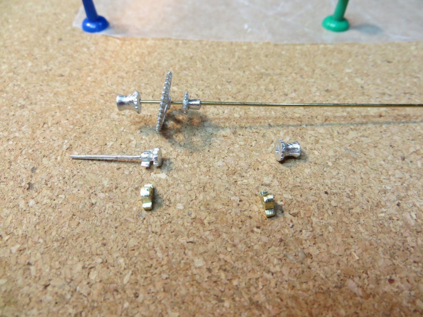
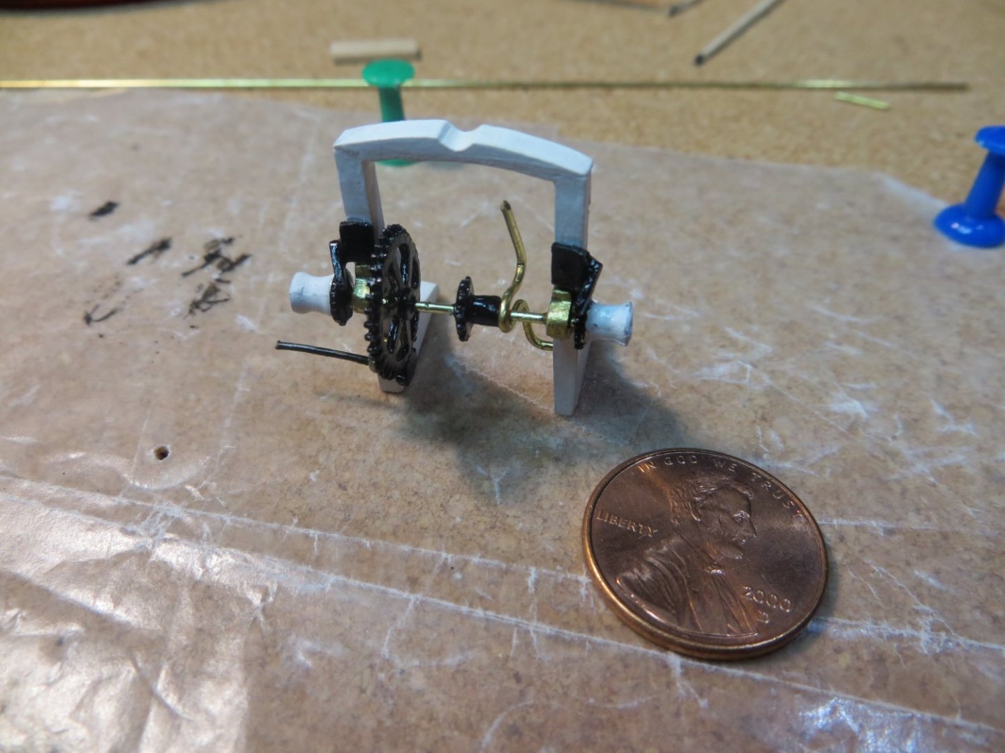
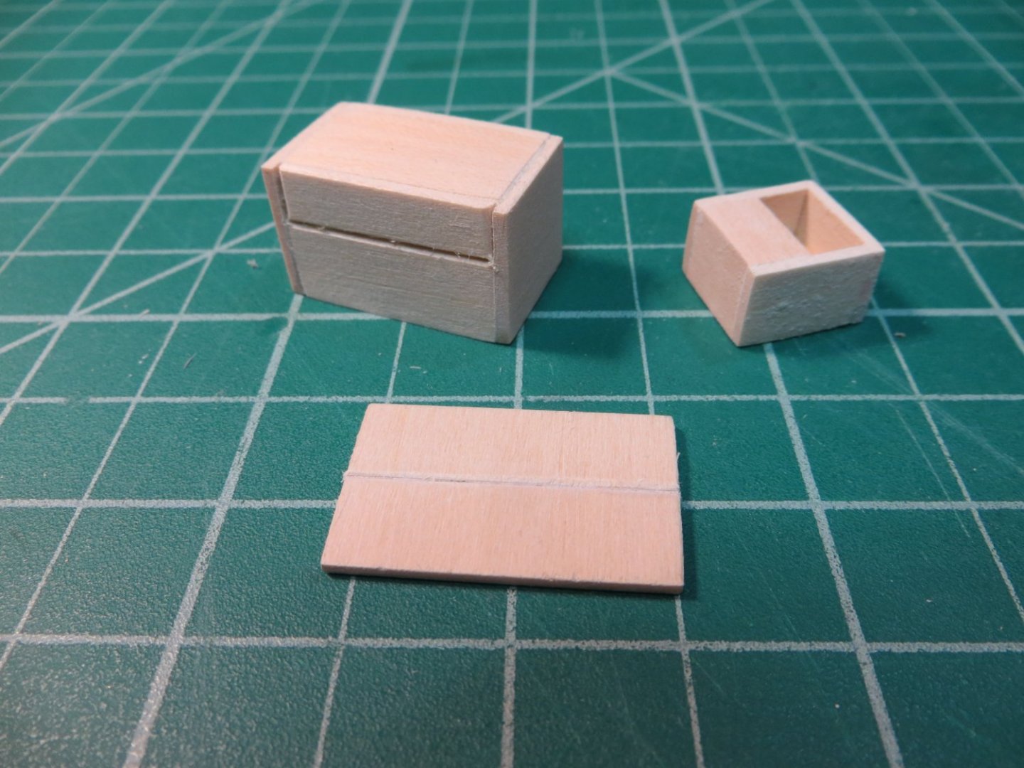
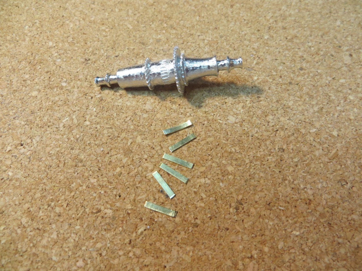
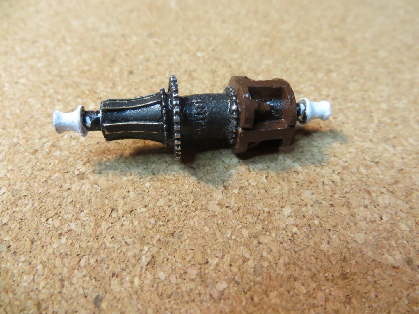
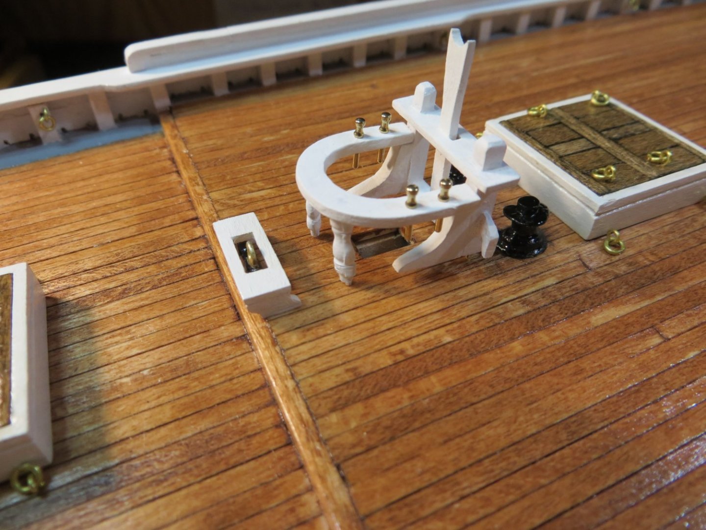
Originally posted June 10, 2021 Engine Boxes & Windlass Machinery Engine and Clutch Cover Boxes – These are made from 2 attached boxes made from 1/16” sheet wood. The dimensions were taken from the plans. After adjusting for the 1/16” sheet wood, I made an inner structure from some square basswood strips that were the proper size. I purchased a bundle of basswood from Hobby Lobby early on for this type of use. In one of the pictures below you can see the underside showing these inner blocks and the sheet wood glued over it. I find this makes for a sturdier and squarer structure. Then I did a couple of extra things. I used my scribing tool to make lines in the cover and front side of the boxes to simulate the access panels. I painted a thin black line in the crack on the top and made hinges from brass strip and rod. The soldered pieces were trimmed and filed to their final shape. I also made a handle for the top cover from brass wire. 3 slits were made in the clutch box per the plans. Everything was hand painted white. The brass hinges were painted with brass paint to cover the solder. Counter Shaft Assembly – These 3 Britannia metal parts were provided in the kit. You have to be very careful not to break the shaft with the gears. The trick is to align the gears with the Windlass gears before gluing the stands to the shaft and cutting off the excess ends to the shaft. I painted everything with black gloss enamel. Set this aside until the windlass is finished. Windlass -- Putting this piece together was challenging for me! Brass strips are for Chain & are on the port side (small gear) and the wooden slats are for rope & are on the starboard side. Here are the construction steps I used. Sorry, I was so focused on building this piece, I didn’t take many pictures of the process along the way! Construction Steps for Windlass 1. File & clean windlass barrel. Sand laser char off of the stands (4 parts). 2. Start on the “chain” (port side). Glue on 6 – 1/16” wide brass strips provided in the kit. Cut them to length and bend them to fit the curvature of the barrel. I was able to position each strip in place one at a time and carefully place a couple of drops of CA thin glue at the edge of the brass. It was automatically sucked into the crevice and formed a great bond. 3. Paint between the endcaps with acrylic black paint. Do not paint the caps. They will be painted white later. 4. On the starboard side cut and glue 4 – 3/32” Square wood strips. Make them a little long. Glue with CA. a. Carve 4 taller but narrower pieces with a curved shape. Only 1/3 of the length. Glue between first 4. b. Fill the gaps between these two pieces with a ‘V’ shaped piece of wood. I made them larger than required and relied on filing & sanding everything to shape later. c. On the end where the stand goes, carve longer pieces with angled ends to fill the gap between the strips. d. Truth be told, I was planning to stain the wood side. But I ended up soaking this wood with a lot of CA glue to get it to hold! There was no way stain would penetrate this wood when I was done. So, I used some brown enamel paint I had laying around. I’m satisfied with the end result. e. After the glue eventually dried, I sanded it down and painted it with the aforementioned brown. 5. Paint the stands white 6. Glue the barrel inside the 4 laser cut wood pieces 7. Paint the end caps of the barrels that stick out from the stands white 8. File, clean, paint and install Windlass Brake Beam, Quadrants & Pawl that go around the Samson Post 9. Glue the barrel in place on the deck so the pawl will touch it at the lines next to the large gear 10. Glue the Counter Shaft Assembly so the port side gear touches the large gear on the barrel 11. Install brass rods between the brake beam and quadrants. I used the larger wire from the kit. 12. Per the plans you are supposed to bend a thin strip of brass to form a guard for the gears. I didn’t like the way this looked and decided to do without it. See the pictures below of the completed Windlass and counter shaft attached to the deck. Some of the black paint rubbed off the brass strips while I was working on the wood end. I liked the way this looked and decided to keep it that way. I will cover the Winch Machinery in the next status update.


- 96 replies
-
- 3
-
-
- model shipways
- bluenose
- (and 1 more)
-
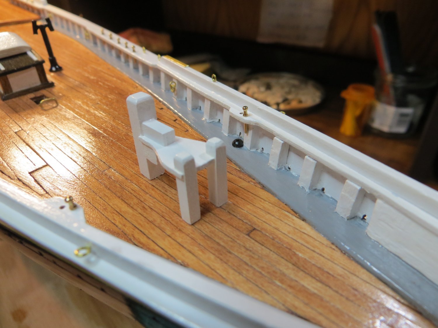
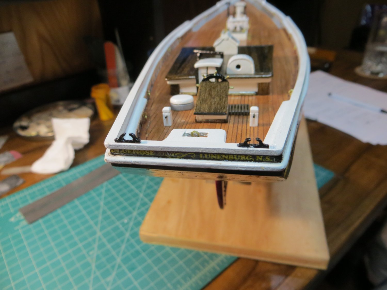
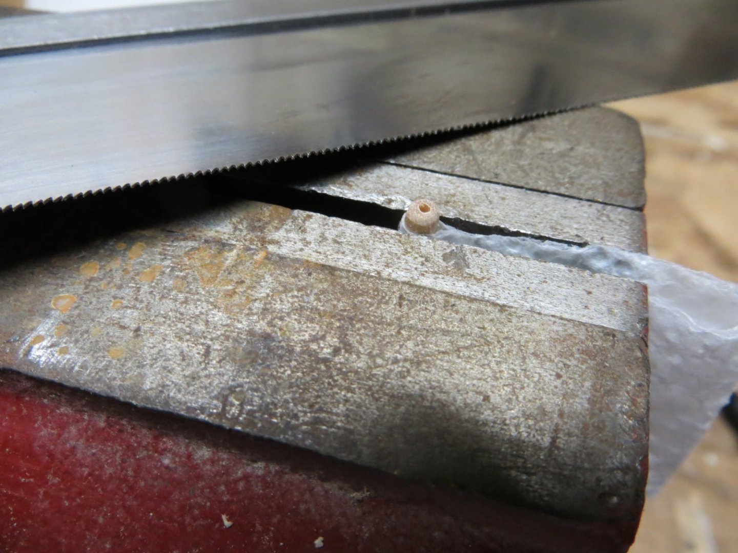
Originally posted May 14, 2021 Fore Deck Miscellaneous Items Next stage is the miscellaneous items on the fore deck. Several of the items were pretty quick and easy to do. The Galley Stack is a cast metal kit provided part that I cleaned up, painted black and installed on the deck according to the plans. The Jumbo Jib Sheet Traveler Horse is another brass staple that is glued in in front of the fore mast. I’ve seen various ways modelers have made the Anchor Pads. I like the look of the ones I’ve seen done with brass. I measured 2 pieces from the thin brass strip provided in the kit. These were CA glued down at the curved end of the monkey rails. I do not plan to paint these. I’ve found that paint does not stick to brass very well. And I like the brass. The next step was adding the various Belaying pins and Eye bolts around both decks. It is best to do these now before the deck gets too crowded and you will not be able to get your pin vise in to the places where holes need to be drilled. I had to study the plans carefully and color coded the marks on the plans where these needed to go. The final two items are the Catheads & Samson Post/Bowsprit Bitts. These were more involved to build and require some more detailed planning. Galley Stack, Anchor Pads, Belaying Pins and Eyebolts Catheads – are two cast metal pieces provided in the kit. They are pretty flimsy and require a lot of careful filing to get them looking presentable. Here are the steps I used to make and attach these. 1. Very carefully clean & file both metal pieces. Drill 2 holes in each part 2. Hole #1 goes through the head from top to bottom. It is toward the back of the head, close to the stem. I used a #73 drill bit. 3. Hole #2 goes into the side of each cathead that faces the bow. It does not go all the way through. The hole needs to hold an eyebolt. 4. Drill a hole in the main rail for the cathead to slip into place. It should be a little larger than the stem. Bend the stems so the catheads hang out over the railing. The prepped catheads were painted black. 5. I followed the process in Suburban Ship Modeler’s website to make a socket for a base that the stem sits in. He used a thin dowel that he drilled a hole in the center of with a #69 pin vise bit. I clamped the dowel into my bench vise, rounded off the top about 1/16” with sanding sticks. Now cut off the top with a razor saw. See the pics below showing this process. Raise the dowel up again and repeat for the second. These pieces were painted black. After drying they were glued under the holes in the railing where the catheads go. 6. The eyebolts that come in the kit are way too big for this tiny cathead. I made the eyebolts that fit into the shallow holes by twisting some of the smaller wire supplied in the kit around a small drill bit. This process is shown in the build booklet in the kit. Trim the end really short and CA glue into the holes. I left the eyebolts brass colored. 7. Install a standard size eyebolt in the outside of the railing just forward of where the catheads are mounted. 8. Set the painted cathead in position. Use the thicker of the 2 wires from the kit to make the holding bar. 9. I didn’t glue the catheads in place yet. This will be done later after positioning the anchors with their rope & chain. They were returned to their zip lock bag for safe keeping. Samson Post & Bowsprit Bitts -- This is actually one piece. It is made from one laser cut piece provided by the kit (for the platform), and the rest is made from strip wood. Two 1/8″ square strips form the bowsprit bitts at the front, basically two legs. At the rear of the structure, the single Samson post is made from 3/16″ square strip. 1. Cut the 5 pieces of strip wood according to the plans. The 2 1/8-inch square and the 3/16-inch Samson post. There is also a platform support block, made from 3/16″ square stock, that will be located right below the platform. Above the platform is a support block for the windlass brake beam, made from 1/8″ square stock. 2. I cut a shallow slot to fit the laser cut platform into the Samson post. The position has to be measured carefully from the plans. 3. Make the usual bevel in the top of each post with sanding stick. 4. Assemble and glue the pieces together using PVA wood glue. 5. Drill holes in the bottom and insert brass rod for gluing to the deck. I used a larger rod for the samson post and a couple of leftover brass pieces that were cut off from the bottom of the eye bolts. 6. Paint the assembly white 7. This piece must be precisely positioned on the fore deck because all the other machinery parts are placed according to where this is located. I took careful measurements from the brass horse to the Samson post and from the inside edge of the buffalo rail to the post. The distance for these on my model was slightly longer than the plan. So, I split the difference and cut just the hole for the Samson post rod with the pin vise. Then I did a mock up of the installation on a scrap board and punched all 3 rods through some tracing paper. I then taped this to the deck based on the hole for the Samson post and made the 2 holes for the bowsprit bitt legs according to the mock up. This seemed to turn out well. We will see when the machinery and bowsprit are installed!
- 96 replies
-
- 2
-
-
- model shipways
- bluenose
- (and 1 more)
-
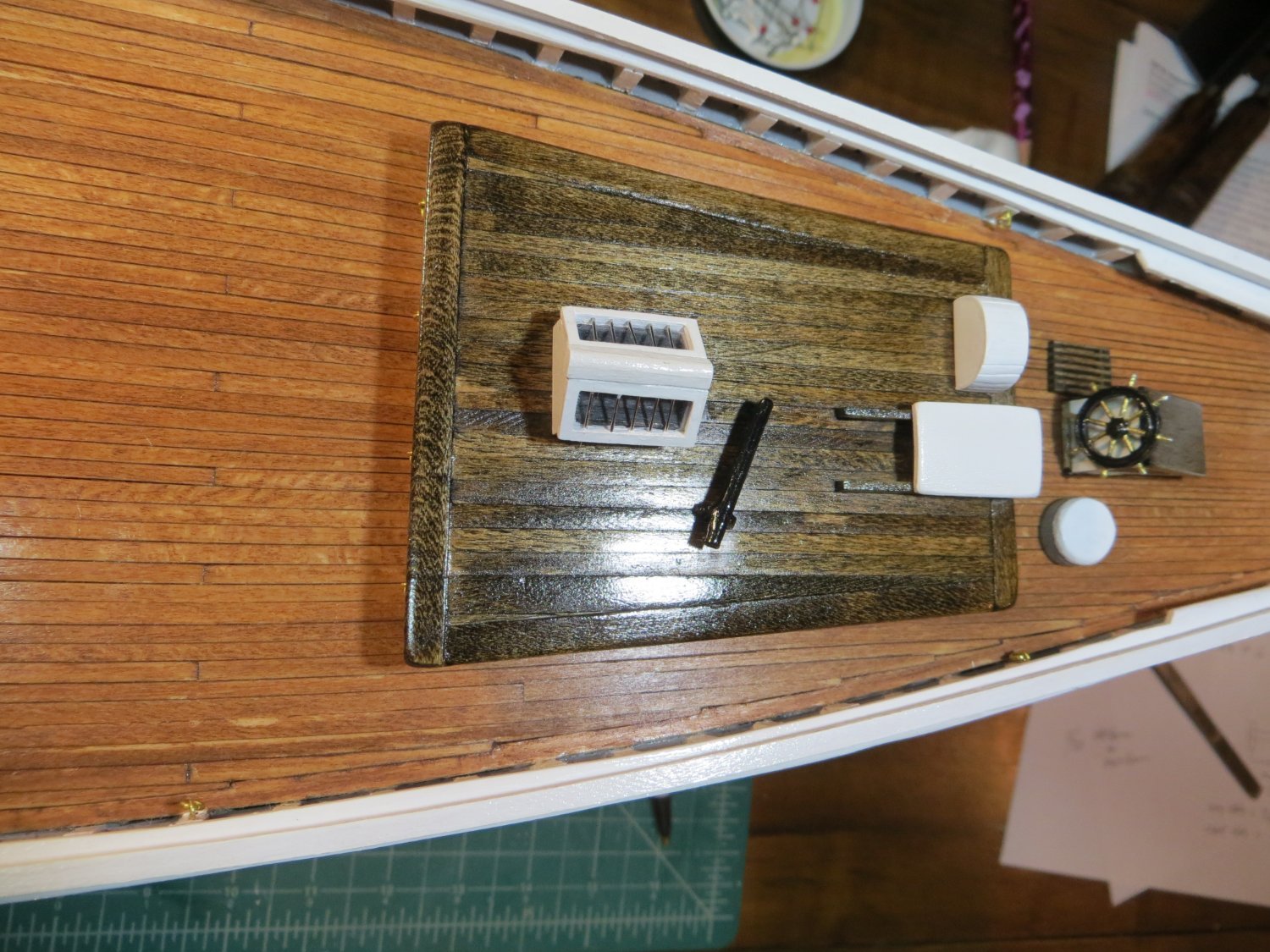
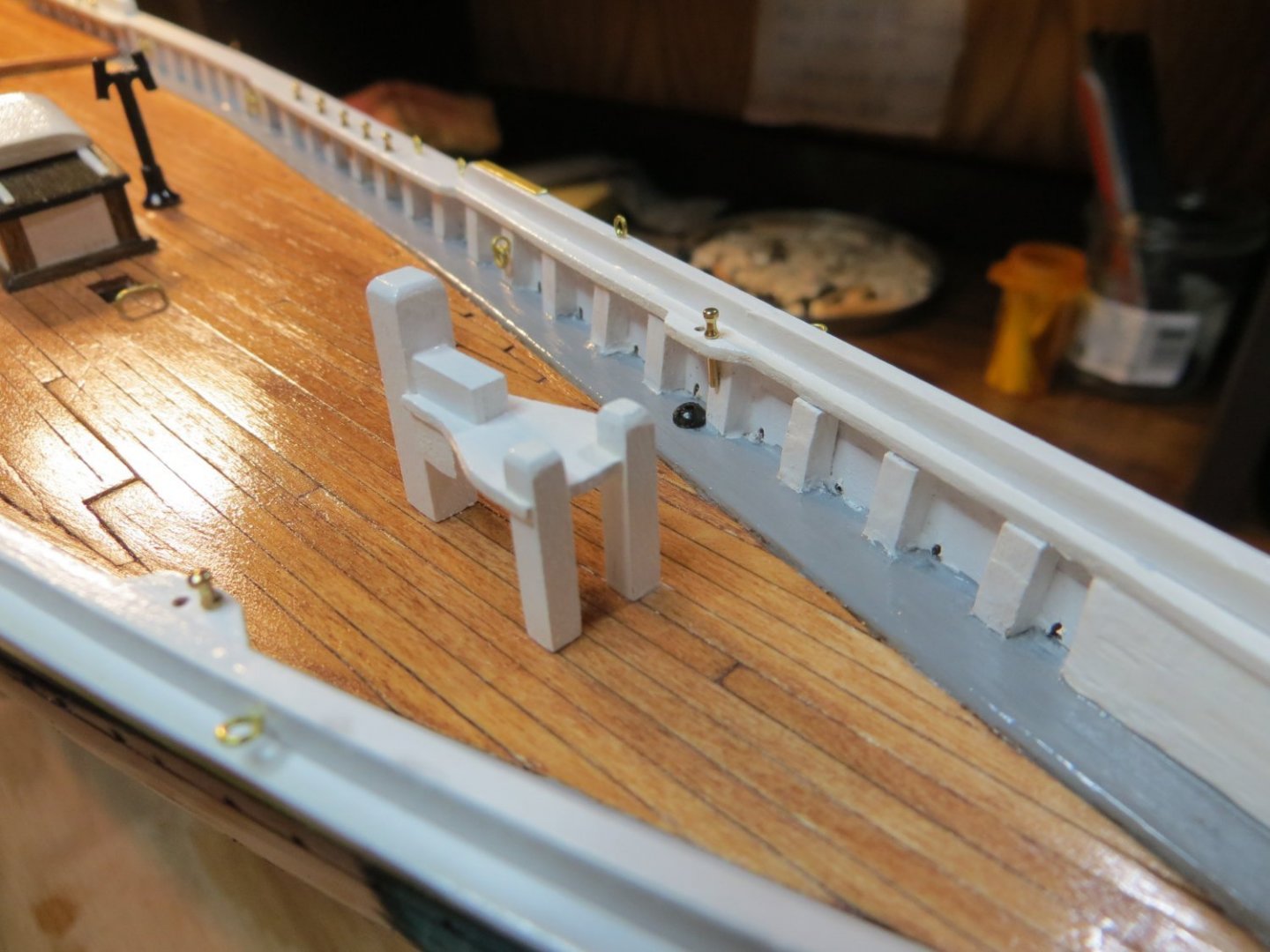
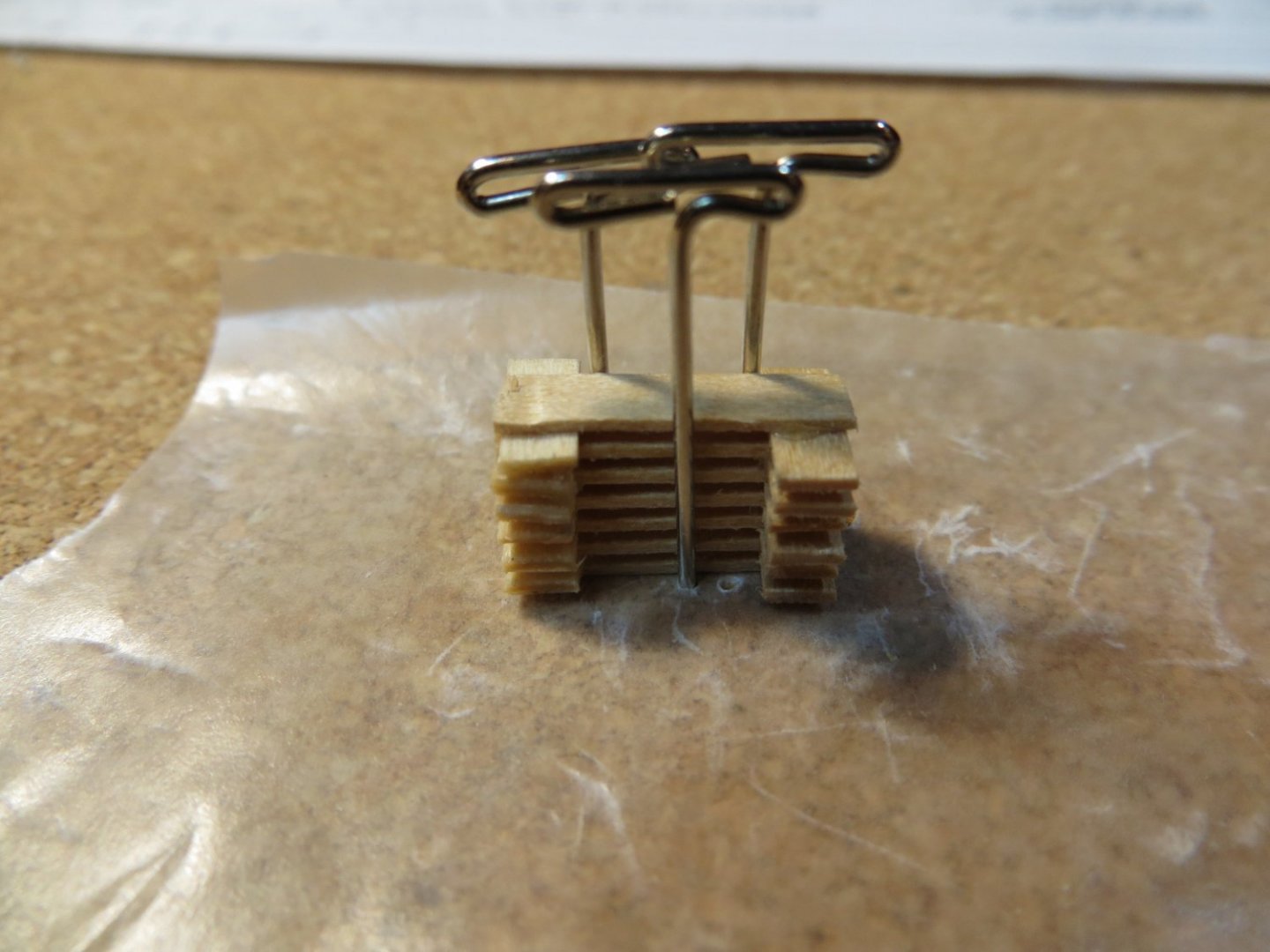
Originally posted May 9, 2021 Quarter Deck Miscellaneous Items Battons – This is a grate-like wooden piece that is glued down on the starboard side of the steering wheel. These slats are supposed to be 1/64” thick strips of wood. But this is incredibly small to work with so I used strip wood from the kit that is 1/32 x 1/8 inch. From this wood I cut 7 long slats @ ¾” long and 6 short slats @ ¼” long. I alternated these long and short slats to form a stack that was glued together. I used T pins to keep the stack squared up. (See the picture below) After the glue dried, I trimmed off the ragged ends and sanded it on a 100 grit piece of sand paper until it was the proper height according to the plans. It was stained with some dark walnut and finished with wipe-on poly. When finished it was glued next to the steering wheel box. Fore Boom Sheet Buffer – is a cast metal part that I cleaned up & painted earlier, at the same time as the main boom sheet buffer. 3 laser cut pieces of wood are supplied in the 3/64” thick set. These were cut out of the sheet, sanded, glued and painted white. I carefully measured the location for the cast metal part and cut holes with the pin vise at the front edge of the quarter deck. The buffer and wood platform were attached using CA glue. Main Sheet Lead Block Horse – This is like a brass staple. I used the same brass rod that I used for the pins on the pintles and gudgeons (0.032”). A length of rod was cut and formed in the shape of a U with pliers. The trick is to get the part inserted square to the deck and centered under the aft platform. Mine did not turn out as perfectly as I would have liked. But I think it would look worse drilling new holes and patching the old ones in the deck! So, I’ll live with it being a bit off center. Quarter Bitts – Cut these from 1/8” square strip stock. They need to be 5/16” tall. I made the bevel on the top with a sanding stick. But I could not cut a decent “chamfer” in the corners near the top. So, I scrapped that effort and used the scribing tool to impress a groove around the entire post a little below the top. This is consistent with parts like the hatches. Instead of making the arms out of wood, I used 0.032” brass rod. First, I used the drill press to put holes in the bottom of the bitts for inserting brass rods. The posts were painted white and I painted the arms with black enamel to make them stand out better. Bilge pumps and Stern & Bow chocks – were made from the Britannia metal part provided in the kit. My bilge pumps were really misshapen and I ended up cutting the top off and turning it upside down. I don’t think anyone will notice. After painting they were all glued in place with CA glue. I attached both the Bow & Stern chocks at the same time. [I did not like the way these bilge pumps looked and I bashed up my own using wood more recently. Pictures to follow once I finish fixing up this build log] Fife Rail @ Main Mast – The fife rail is the last piece to go on the quarter deck. The Bluenose kit provides most of the parts as laser cut wood or Britannia metal for the two fancy stanchion legs. However, I had trouble right away. After filing and cleaning up the metal stanchion legs, I tried to dry fit them into the laser cut curved rail and it broke in two. You can see the broken piece in the background of the pic below. Rather then fix this flimsy 3/64” piece, I decided to make a new one using 1/16” thick basswood. I traced the shape and size onto a 1/16” wood sheet that I had and rough cut it out using the thin saw and a #11 knife blade. I then filed and sanded it to the finished shape. I cut 1/8” square posts and beveled the tops. A bit of sanding was required to get a good fit into the holes on the laser cut cross bar. There is also another bar that needs to be cut from strip wood to fit at the bottom. I notched this to hold the boom crutch, which is another kit provided laser cut piece. I drilled holes in the bottom of the “knees” for inserting some brass pins to use for gluing the finished fife rail to the deck. The hardest part was keeping everything squared up and straight when gluing it together. I glued the pieces in steps to achieve this. After assembly, there are some tiny wood pieces called “snatch blocks” that need to be attached to the outside of the posts. These were carved from strip wood. There are also 5 belaying pins that need to be attached. Holes were drilled for these. Once fully assembled (minus the belaying pins) I painted the entire fife rail white. Since the fife rail goes around the mast, I’ve read that you should wait until the mast is ready to be added before gluing this piece down. The fife rail does have to go in before the mast. The mast goes in at a slight angle. Shaping the base of the mast and setting the right angle should be easier without the fife rail. The mast’s angle will determine the final position of the fife rail. [Shortly after this, I glued down the fife rail. I determined the slight angle of the mast was not going to affect the fife rail.]


- 96 replies
-
- 2
-
-
- model shipways
- bluenose
- (and 1 more)
-
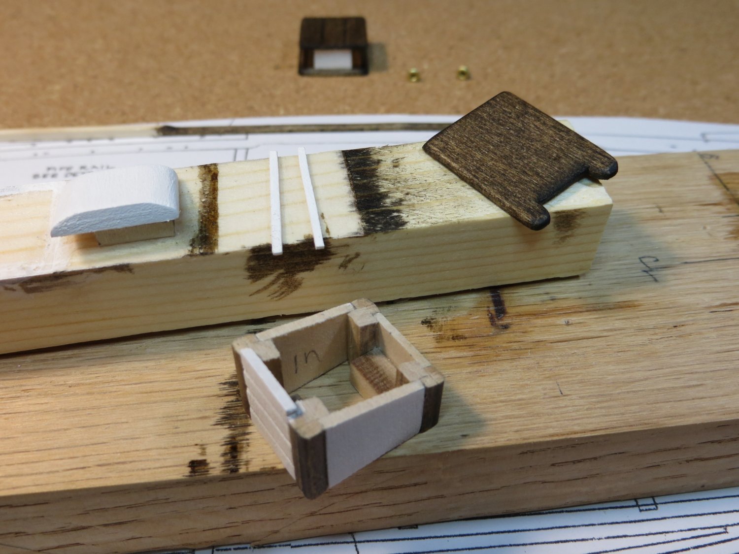
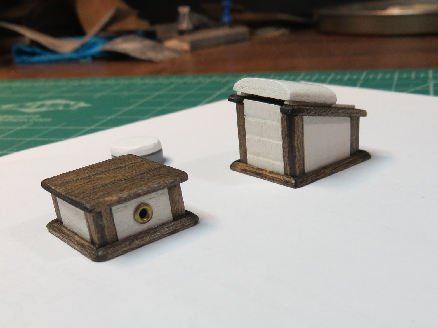
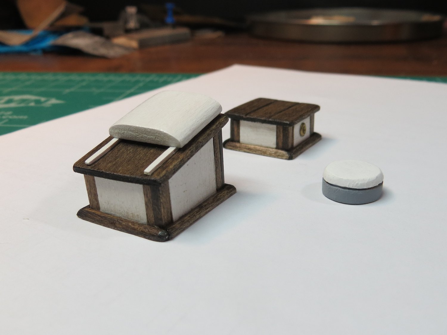
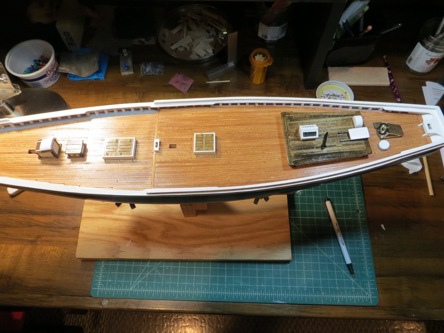
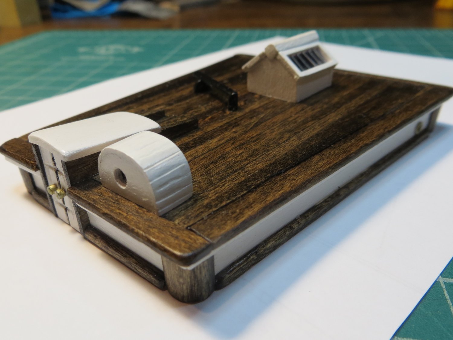
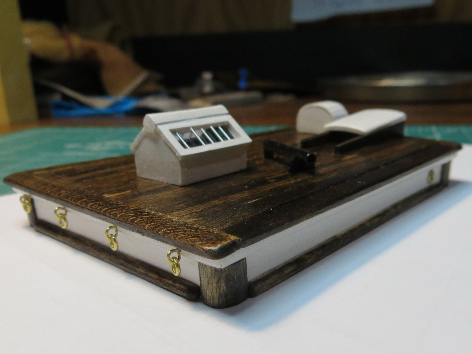
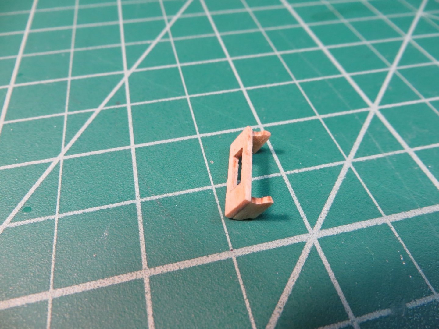
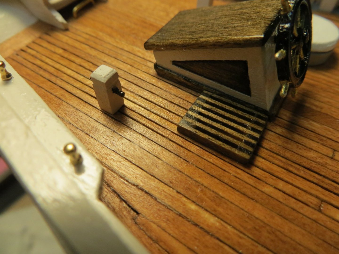
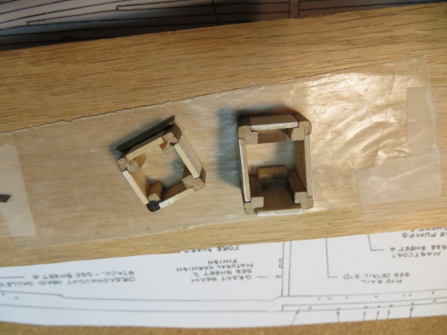
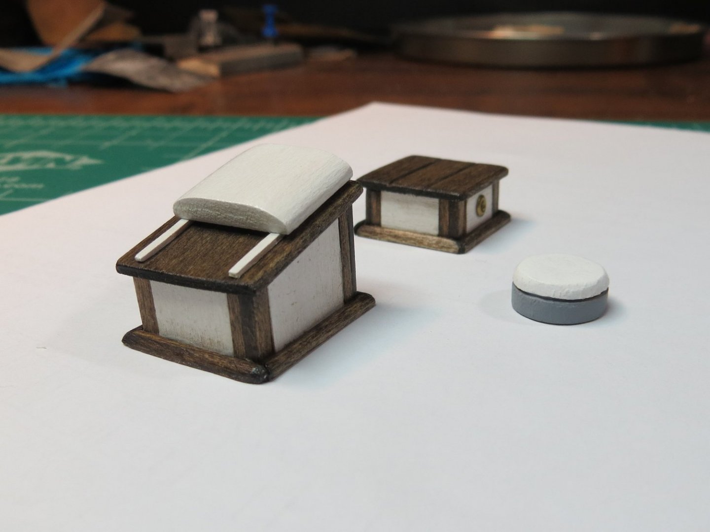
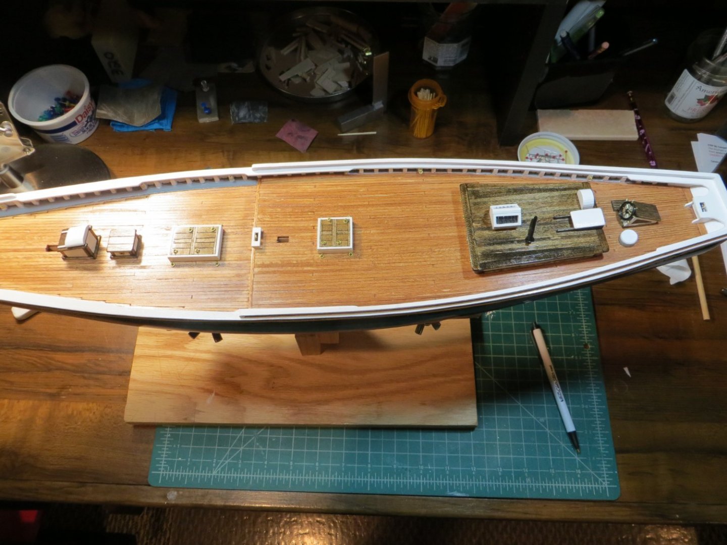
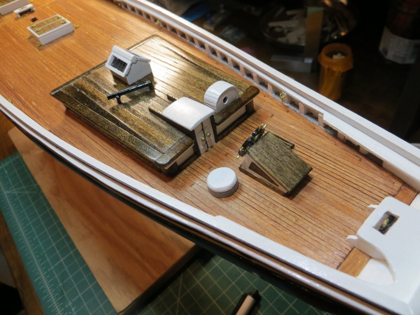
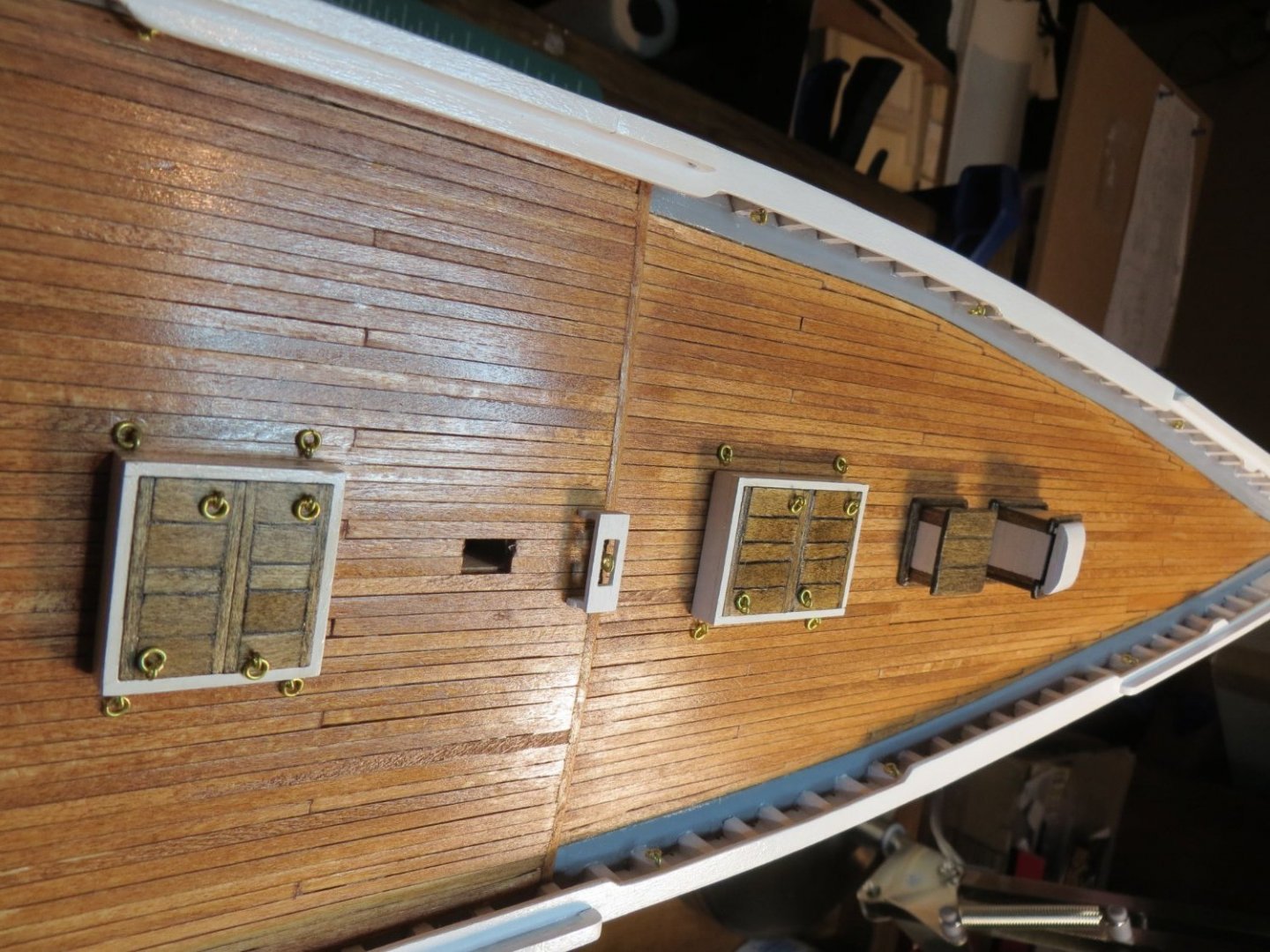
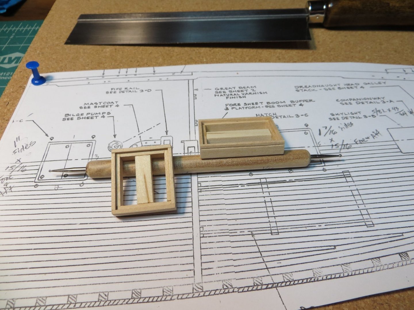
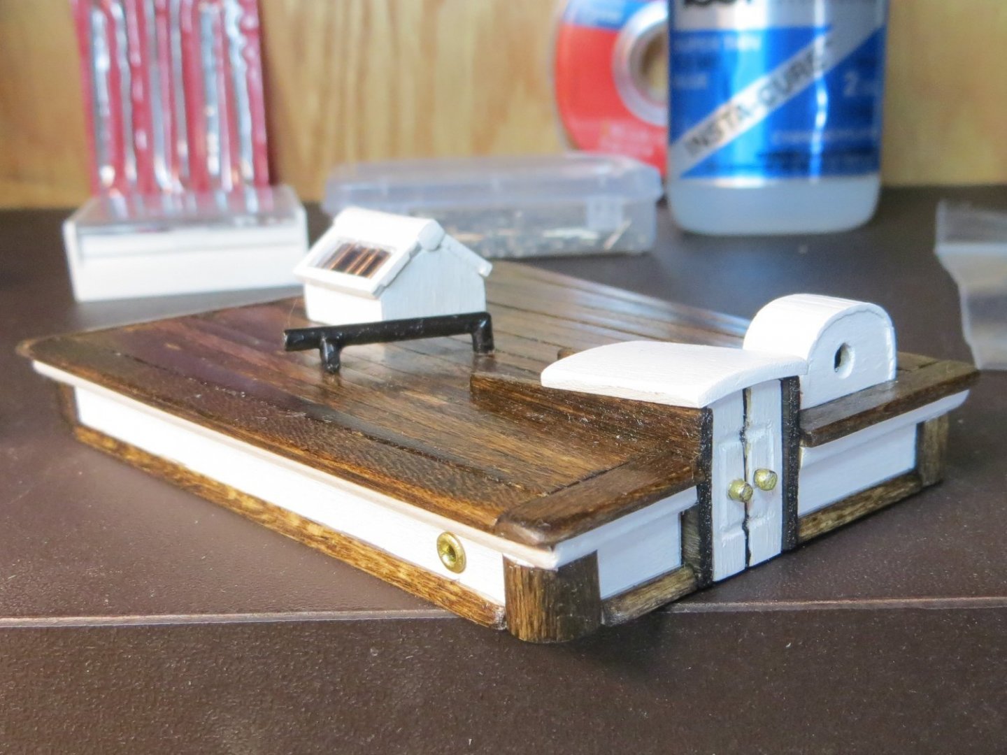
Originally posted April 20/2021 The next step in my plan is to build the Companionway and Skylight for the Foredeck. FYI, before each significant step in the process I start by putting together these construction plans. They are a compilation of my study of the build logs on this forum, from which I take the best ideas and blend them with how I want my version of the Bluenose to be. As mentioned previously, I rely heavily on the website of Suburban Ship Modeler. For the most part, I follow his build plan. I also take a lot of ideas from CPDDET on this forum, as well as a few others. I don’t find the Bluenose instruction manual to be very helpful and I have not purchased anyone’s practicum. As a newbie on my first real kit build, I’ve learned a lot in the past 11 months. Construction Plans for the Companionway 1. Since the companionway and the skylight have a number of similar pieces, I made a few parts together. 2. I first made the corner pieces from 1/16” square strip wood glued to a piece of 1/8 x 1/16” deck strip wood. Since this structure is smaller than the cabin, I downsized the corners to match the smaller scale. I glued it to a 1/8” square strip for attaching the sides and for strength. I hand sanded the assembly to soften the outer edge but still keep it square enough for overlapping the coamings. Made the length of this assembly long enough to use for the 8 corners of both structures. I even made it a bit longer so I had a handle for staining. 3. Used Sanding Sealer and then stained the corner pieces my Minwax dark walnut. 4. Traced the shape of the walls from the plans onto a 1/16” basswood sheet. Cut these pieces out. At the same time, I also cut the skylight sides. Since the 4 walls are the same, I cut one long strip at the proper height. Painted it white and then cut them into the required lengths to simplify the assembly. 5. Before painting, I used my scribing tool to impress lines to simulate separate boards in the c-way doorway. 6. After everything dried, I glued the corners and sides together for both using my jig to keep everything at a 90. 7. After glue dried, I turned both structures upside down and outlined the shape onto a 1/16th inch sheet for the roofs. I added an extra 1/16” for overlapping the roofs and sanded the edges to round them off. The main roof on the c-way also requires the front edge to be notched so it appears that there is a hole when the hatch slides back. This roof is stained. 8. I cut some tiny square rails on the roof for the hatch to sit on. These are painted white to contrast against the roof. 9. The hatch appears to be taller (thicker) than the one on the main cabin. I cut a piece of 1/8“ thick sheet wood to the required size. I sanded this to shape with sanding sticks. Painted it white. 10. The finished parts were glued together Construction Plans for the Skylight 1. After cutting the painted sides to length, I drilled a 9/64” hole in the port and starboard sides. Later I inserted a pair of brass port lights that Dave (CPDDET) was kind enough to send my way. Thanks Dave!! 2. The base of the skylight was assembled in the same manner as the companionway. 3. I measured and cut the roof for the skylight the same way as the companionway. But, for this roof I scribed a couple of lines to simulate a planked roof. I didn’t bother with this detail on the c-way since the hatch covers most of it. 4. Finally, I made smaller scale coamings for both structures. I used a piece of hull planking that I cut in half. So, it started out as a 1/16” square. I sanded the outside edge on an angle to make it look like a piece of molding that is thinner at the top and 1/16” at the bottom. I made one long piece and cut it up to fit both structures. These are stained. I mitered the corners and rounded off the corners. Cutting these to fit was really a challenge because they are so small. It’s hard to hold them and measure and mark the length all at once. Unidentified Object I also made the unidentified object at this time. I found an old dowel in my scrap wood pile in my workshop that was close to the right size. I rounded off the top edge with sanding sticks and then cut a groove near the top to simulate a lid. I cut it to the height shown in the blueprint plans. Painted the lid white and the bottom the grey from the waterway. I think it looks pretty good! Here are some pictures. This completes the main building structures on the deck. Corner Pieces and sidewalls prepared for assembly: Companionway & Skylight under construction: Pictures of the deck with structures installed:


- 96 replies
-
- 6
-
-
- model shipways
- bluenose
- (and 1 more)
-
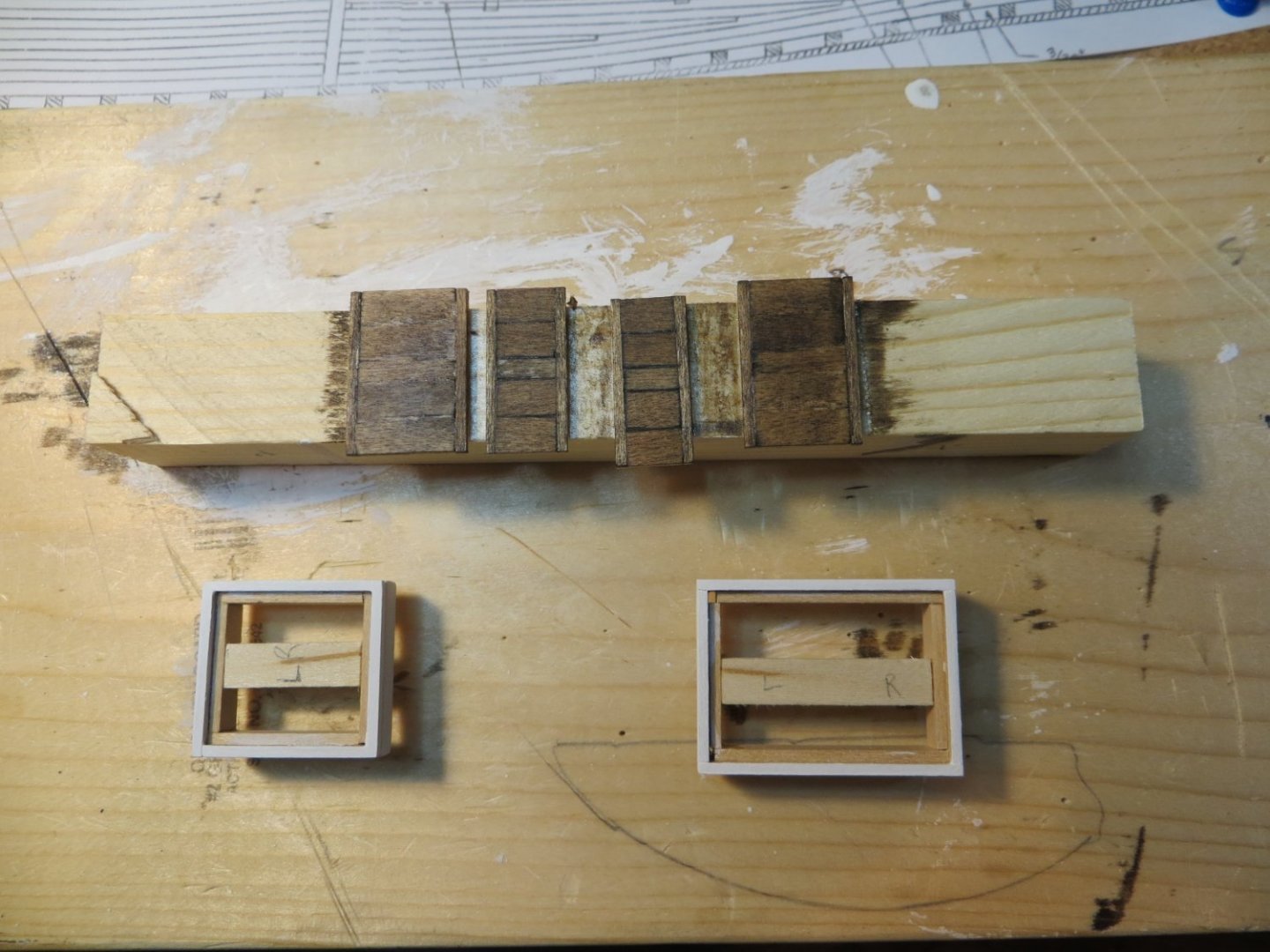
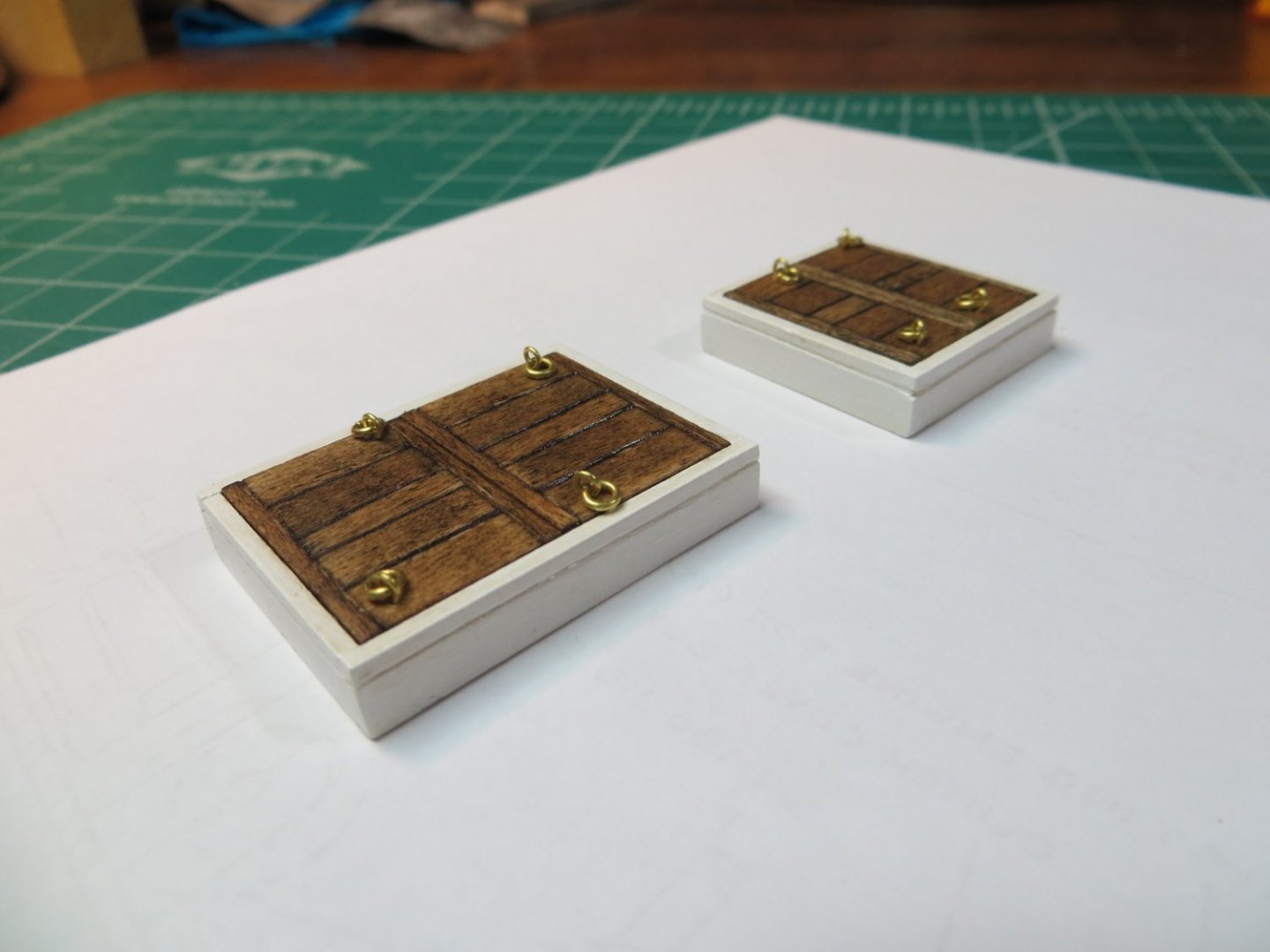
Originally posted April 14, 2021 2 Hatches The next step was building the 2 hatches, one each for the fore deck and quarter deck. These were pretty straightforward to build. Here are the construction steps I used. 1. Measure and cut the outside frames according to the plans. Use lap joints w/ short ends at the fore & aft. 2. Measure and cut the inside ledge to hold the lids. I also inserted a center brace to provide added strength and another place for gluing/holding the lids. 3. Start gluing the sides together. Make sure they are perfectly square using one of my jigs. 4. Cut in the small cove around the outside of the frame using my new 1/32” ball tip stylus to impress the wood. You can see this tool in one of the pictures below. 5. I wanted to make the lids according to the plans, in two halves using individual planks. I measured and cut really thin boards to frame the planks and also the planks themselves. After constructing the lids I dry fitted them and rubbed the hatch on a sheet of sand paper to make sure they were flush with the outer frames. 6. Paint the outside frames white and the lids with the dark walnut stain. I started using sanding sealer whenever I stain to help even out the color. The basswood planks seem to vary a lot in the amount of stain they will absorb. 7. Sand the bottoms to fit the curvature of the deck. I used the same technique as with the cabin. 8. Seal them with Minwax satin wipe on poly. 9. Add the eye bolts and rings according to the plans.
- 96 replies
-
- 6
-
-
- model shipways
- bluenose
- (and 1 more)
-
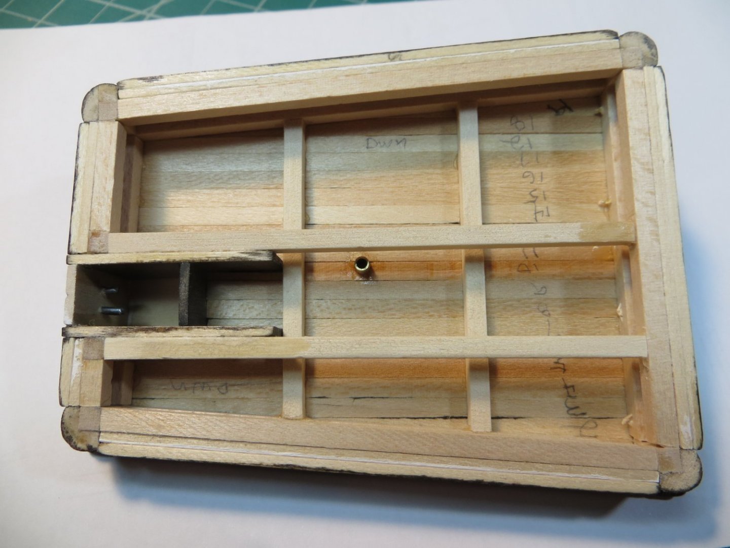
Originally posted April13, 2021 Main Cabin Next I built the Main Cabin that goes on the quarter deck. This involved multiple pieces to be built. The most difficult part for me was the skylight. Here are the steps I used. 1. Make a copy of the cabin from the plans, as seen from above and attach to a pin board for the assembly. 2. Make the 4 corner posts from square stock and attach the decorative corner pieces to them. The corner pieces need to be cut short to allow space for the molding under the roof. Stain these Dark Walnut before gluing to the 4 posts. It took me a couple of attempts to get this to turn out to my satisfaction. Here are the steps: a. I glued a 1/8 x1/8 square piece of strip wood to a ¼ x 1/8” piece. Then I double face taped it to a long scrap of triangle shaped block for sanding. b. I cut a long strip of sand paper and pulled it back and forth across the top corner of the piece until it was nicely rounded. I cut it into 4 lengths about ¼” each after sanding. 3. Cut and glue 1/8" square inside framework to the posts according to the shape of the cabin right on the plans. Also add interior frames: Two deck level beams for the companionway and two more running perpendicular at the height of the roof frames were created and glued. (See the picture of the underside of the cabin to see how the inside framework was attached to the corner posts.) 4. Cut and attach the companionway walls using 1/16” stock. Stain these walls with Drk Walnut. 5. Cut, paint white and attach the cabin walls using 1/16” stock. Fit these between the decorative corners. 6. I made the side molding that sits above the side walls & under the roof from 3/32” square strip stock. The piece ended up being 1/16” tall x 3/32” out from the wall. I used a jig to hold the length of the wood down while I rounded off the outside edge. The jig was used to keep the bottom edge flat (the edge that faced the roof overhang). 7. At this point check the “camber” of the cabin sitting on the deck. I cut a piece of 120 grit sandpaper that was larger than the cabin and held it down in position on the deck. Then pull the cabin fore and aft until it sits on the deck without rocking from side to side. 8. Drill the portholes in each side wall. Port near the doors; Starboard near forward corner. 9. Next plank the roof around the companionway walls. I liked and so made the outside perimeter wider then the rest of the roof planks. Built this first then filled inside with 1/16" hull planks. 10. I ended up making the cabin doors with a stylus impressed rectangle around the door handles. I made brass door handles from tiny finishing nails painted w/ brass. Made the doors from one piece of wood and carved a shallow line down the middle. I painted the inside of the line black w/ a tiny brush to simulate the gap between the doors. 11. Make the companionway hatch roof from 1 piece of 1/16” thick sheet. I soaked it in water and rubber banded it around a coffee mug to get the proper curve. Painted white. 12. Build the Skylight. Used an interior block of scrap wood to get the right dimensions and glued the sides to it. I used very thin straight pins for the bars and a piece of plastic packaging for the windows. There was a lot of trial and error building this piece. 13. Made the vent pipe from 3/32” brass pipe like others have. Cut on a 45 degree angle and soldered together to form a 90. Drilled a hole with my drill press through a small piece of brass strip to make the pipe holder. I cut the strip across the center of the hole to form a cradle for the bottom of the pipe to rest on. This end was cut off the rest of the strip and soldered to the pipe after filing to shape. Painted it with black enamel. A 3/32" hole was cut in the roof and the assembly was glued in place. 14. Built the Compass Box from 1/16” sheet stock attached to a short solid base. Front and back were cut & double-face taped together and sanded to shape. Cut short pieces of decking boards that were cut in half length-wise to make the top cover. I made them longer than required and sanded them down flush with the box after glue set. Wish I had left a little overhang with it around the front and back sides. Painted white. 15. Although I'm building Bluenose as a fishing boat (not racing boat), I didn’t add the bait cutting boards on top of the cabin. I thought they would hide too much of the roof perimeter that I like! 16. Inserted brass "port lights" into the port holes.


- 96 replies
-
- 3
-
-
- model shipways
- bluenose
- (and 1 more)
-
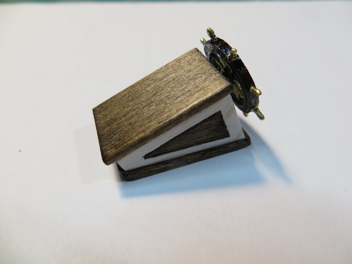
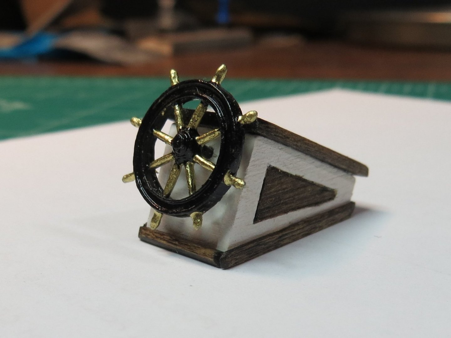
Originally posted April 13, 2021 Wheelbox For the past month and a half I've been working on the structures on the deck. I will provide a few posts to cover this. I didn't start taking construction stage pictures until I was half way through this step. Will provide some construction details, but I only have finished pictures of the steering wheel box and the main cabin. For these deck structures, I decided I wanted to stay close to the "burnt umber" color in the plans, but I prefer the richer look of (Minwax) dark walnut stain as opposed to the burnt umber paint they recommend. I started with the wheel box since it is small. For each of these structures, I photocopied the plans and used the cutouts from these over carbon paper to transfer the shape and size to 1/16" basswood sheet wood for the side walls. I used my thin saw with it's miter box to cut out the basswood pieces. For the wheel box I cut some scrap wood to use as a filler block to provide a base to glue the sides to. For the inset on the sides I first covered them with masking tape then overlaid the photocopy of the plan to the side and cut around the triangular shaped groove with a #11 blade. I removed the tape from around the inset area and then painted everything that needed to be white. Then I removed the masking from the inset and re-taped with yellow Tamiya tape to cover the white part. The inset was stained with dark walnut. This turned out pretty well I think! The roof was cut from a single piece of 1/16th" basswood adjusted to provide the proper overhang on the sides. The edges were rounded off by sanding. For the coamings, I used really thin pieces of deck wood leftover from cutting the aft quarter deck tapering. Coaming size was 3/64 x 9/128“ when I finished sanding. I mitered the ends and rounded off the outside corners. A couple of coats of Minwax satin wipe-on poly completed the wheel box. I painted the kit provided Britannia ship's wheel with Testor's black and brass enamel paint. A 3/64" bit in my pin vise was used to make the hole in the box.

- 96 replies
-
- 3
-
-
- model shipways
- bluenose
- (and 1 more)
-
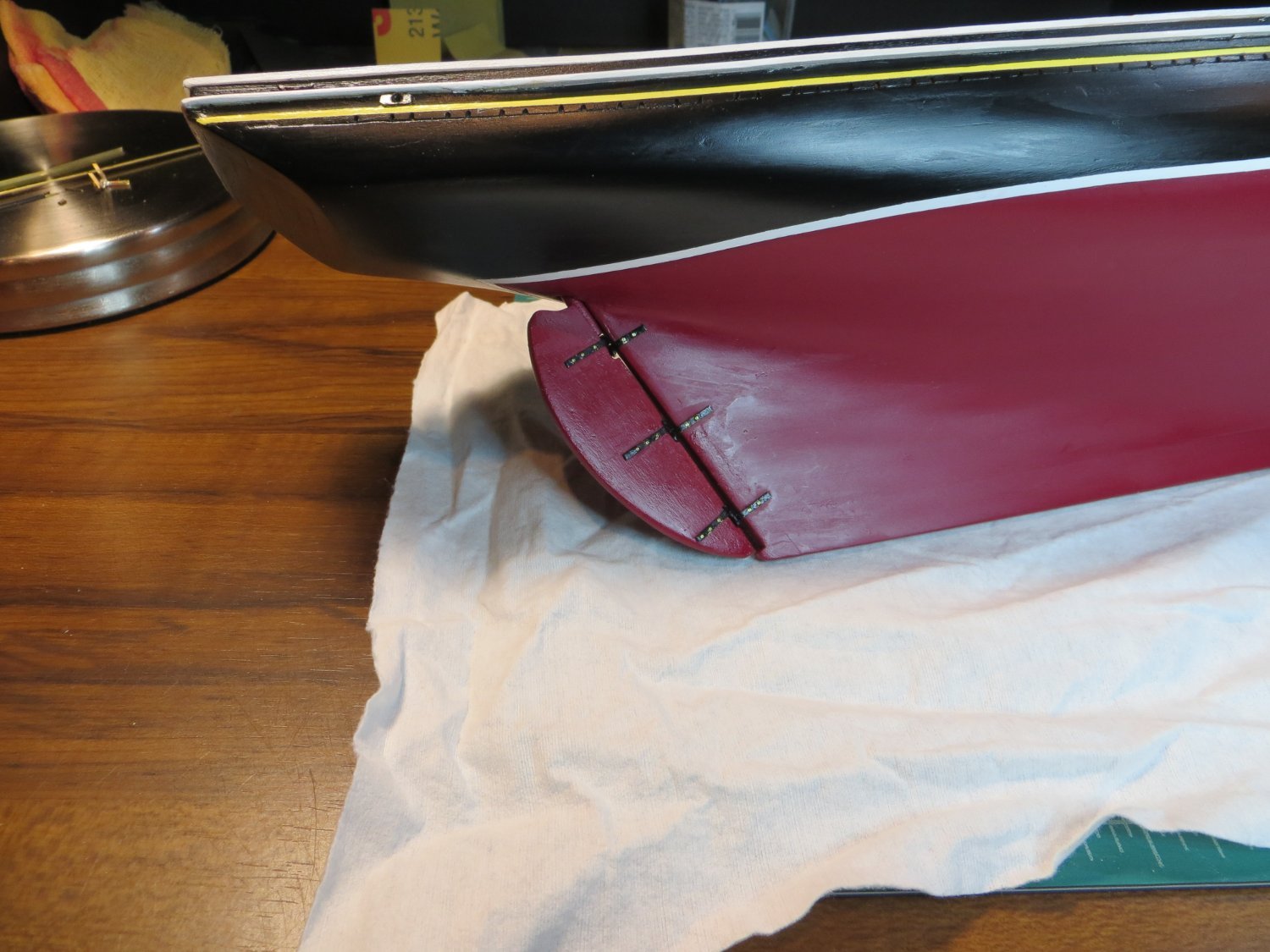
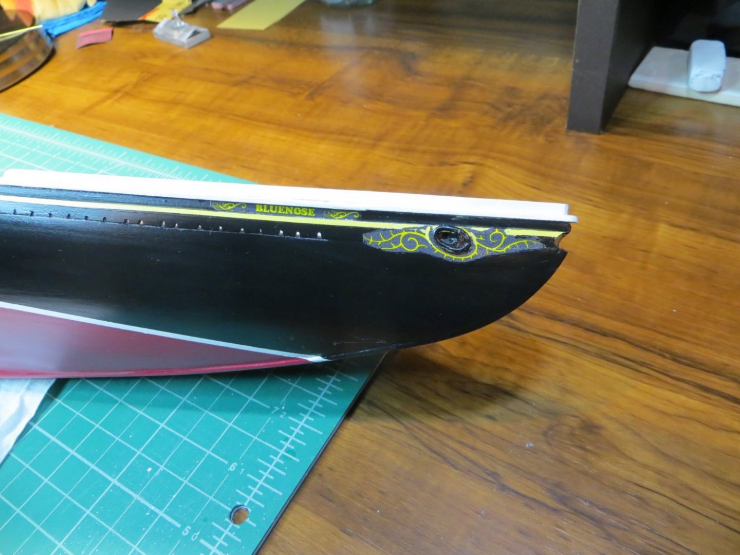
Originally posted Mar. 26, 2021 Decals for Scrollwork n February I added the ships nameplates, the bow scroll work, added the rudder and coated the entire lower hull with 2 coats of Minwax rub-on satin finish polyurethane. The ship building community uses a variety of methods for doing the nameplates and scrollwork. The coolest scrollwork I've seen was done be Suburban Ship Modeler. Dave used his 3D printer to create an amazing replica. I don't have one of those and I didn't think I could convince my wife we needed one, so I decided to try making these with Decal paper made for an inkjet printer. I made the Bluenose nameplates and the scroll work using Microsoft Paint 3D in combination with Powerpoint to create something I could print on the decal paper. The greatest challenges were making the artwork small enough to fit in their positions on the ship and getting the thick decal paper to run through my inkjet printer. It took several iterations before I got it right. I also made a mistake by buying clear decal paper. This was a bad choice because the yellow ink was barely visible against the black hull. I scrapped this first effort and purchased white backed decals. I also had to redo the 3D artwork so that it had yellow print on a black background. This whole process took longer than I expected. Next was the rudder. I wanted to make a working rudder similar to what Dave did on his Suburban Ship Modeler website. Making the pintles and gudgeons was my first effort at hobby scale soldering. I really like the way the brass "nails" look against the black pintles & gudgeons. Dave goes into great detail on how to build this. I'm real happy with the way mine turned out and the rudder even turns! The last step to completing the hull construction was applying the polyurethane.


- 96 replies
-
- 4
-
-
- model shipways
- bluenose
- (and 1 more)
-
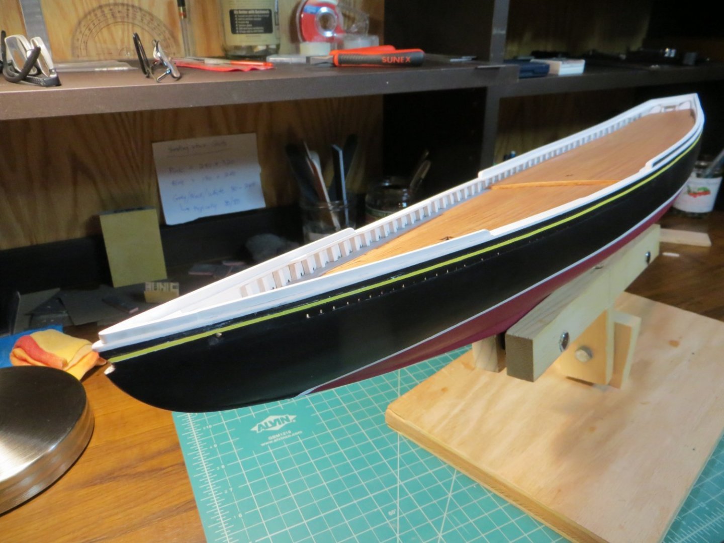
Originally posted Mar. 26, 2021 Railings I spent the month of January working on the railings. I used the general process from the blog of CPDDET. I purchased a pack of 1/16 x 3 x 24" basswood sheets and traced the shape of the hull directly onto one of these sheets in order to make the rail in 1 piece. I traced both sides separately to account for differences between the port and starboard sides. But, before that I had to attach the bow and stern pieces to provide the ends. The laser cut piece provided for the bow fit perfectly. However, the stern was not even close!! I see this is a pretty common problem for most builders of Bluenose. It took me 4 tries to measure, trace, cut and finesse a piece of basswood sheet into something that approximated the shape of the stern! And this still didn't fit right because the tail of my ship is not exactly perpendicular to the rest of the hull! In order to get it to fit, I ended up cutting my beautifully carved piece into 3 sections, gluing them on separately and then filling and sanding the gaps in between until I ended up with something I thought was acceptable. I know my stern is more squared off then the sleek curves that the real ship has, but that's just how mine turned out! I blame it on forming the stern block entirely by hand. Maybe next ship I will have to invest in a Dremel. Actually, creating the main rails as one piece in between the bow and stern went pretty smoothly. I used the technique of placing a dot of CA glue on every 3rd or 4th stanchion and gluing the rest with PVA. I had a lot of trouble keeping the rail in position so that it had the perfect 1/32 inch outboard overlap and the inboard side flush with the stanchions. I used rubber bands to hold it, but these caused the outboard edge to slide in a bit as the glue set. I think this will cause me to have to make a concession on the deadeyes. There is not enough overlap in one spot to run the deadeye through the railing and end up outside the hull. So, I plan to use the black cardboard trick to make the chain plates. I think I can make that look pretty good. Next up was the Buffalo rail and Monkey Rails. These steps went smoothly and I'm happy with the way they turned out. I was really worried about cutting the hole for the bowsprit. I did this before building the railings. As I mentioned in a previous post, I wasn't sure how you guys do this, but nobody offered any advice! So I stepped out in faith... I started with a moderately sized pin vice bit and then moved to a large one. Then I gradually made the hole larger using files. I cut a piece of dowel from the kit, as provided for the bowsprit. At this time, I did not widen the hole completely. I intend to wait until I have the bowsprit sanded down to the correct shape and size. I don't want to end up with a bigger hole then I require!

- 96 replies
-
- 6
-
-
- model shipways
- bluenose
- (and 1 more)
-
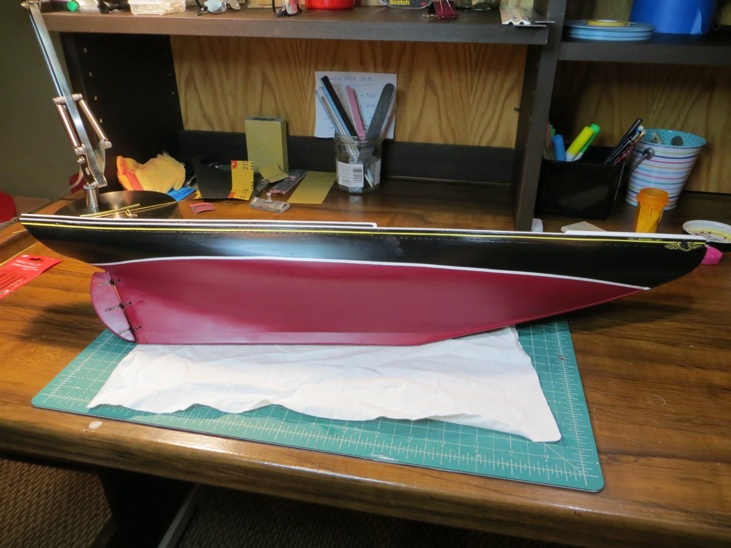
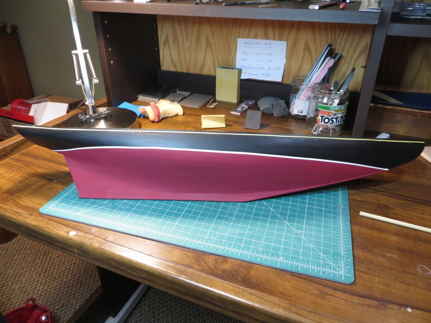
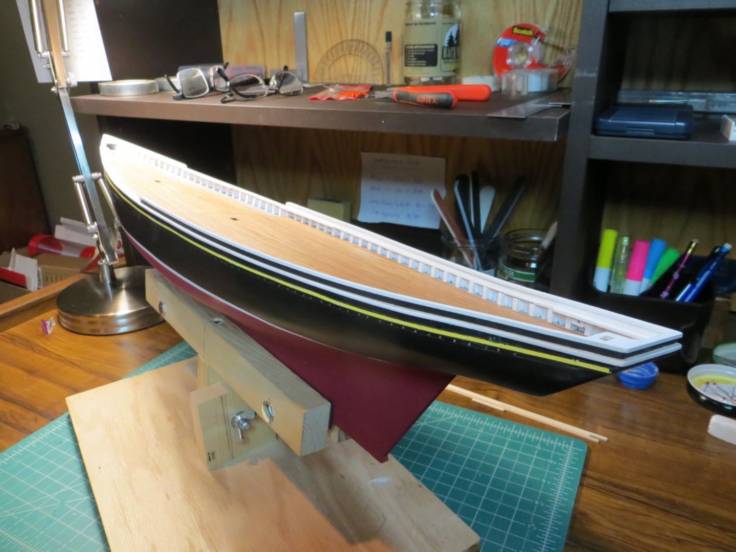
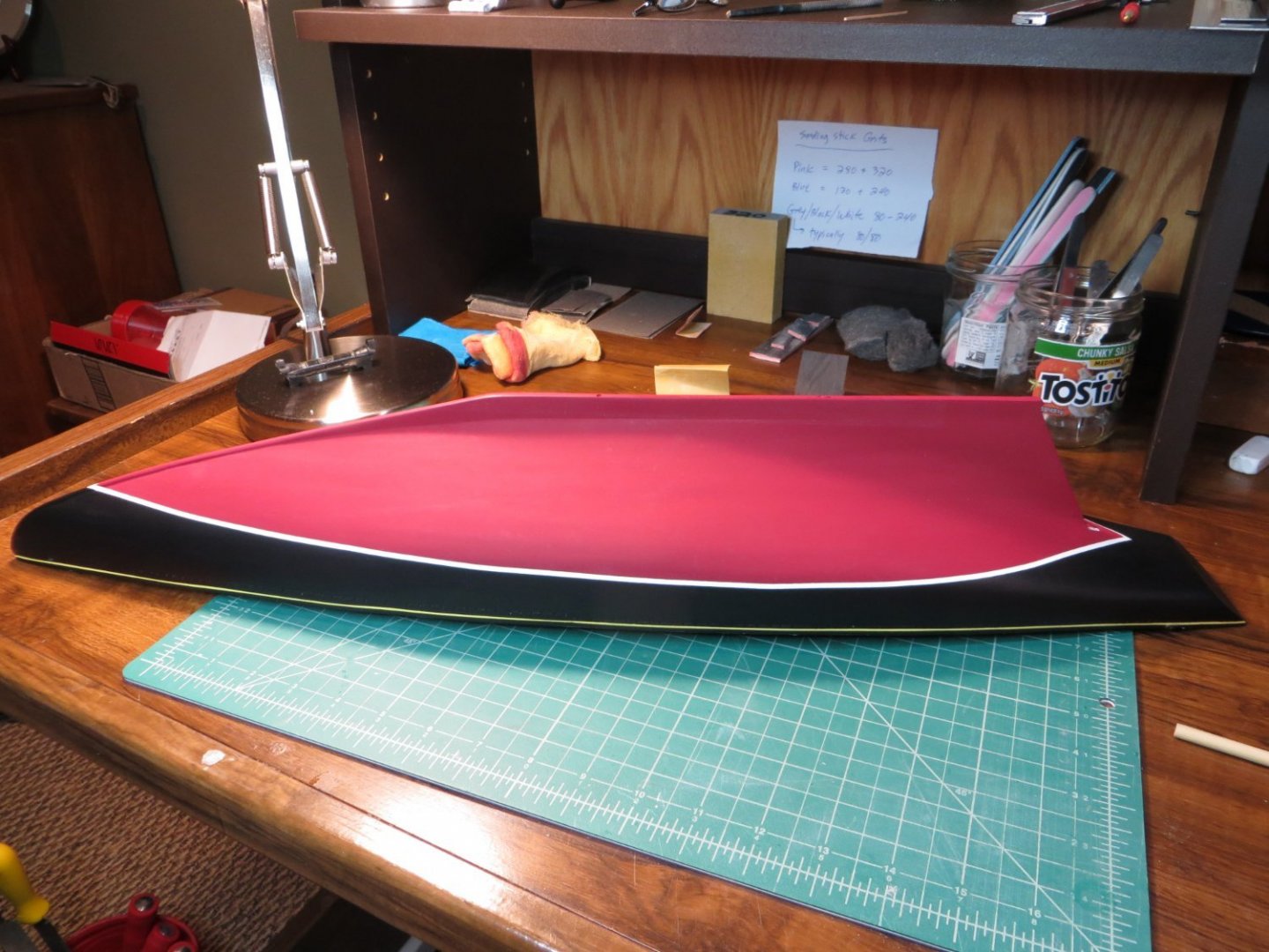
Originally posted Mar. 25, 2021 Painting the hull & Staining the decks Around mid December, I completed painting the hull and staining the deck. I used my new Paasche Talon airbrush with Vallejo Air paints that I purchased after scrapping the Model Expo paints. Unfortunately, the post office lost my return shipment, so I was not able to get the refund promised! Oh well, there has been a lot to learn with this hobby! I struggled a lot trying to find the best color matches. For anyone who is going through the same struggle, here is what I used to produce the results in these pictures. Basic colors are Black 71.057, White 71.001, Light Gray 71.050. I really liked the way that Red 70.926 turned out below the waterline. For the Yellow stripe I went with Light Yellow 70.949. The hull was also primered and puttied multiple times before painting. I found the Tamiya putty to work better then the Elmer's wood putty on the hull. Wood putty left little dimples that I could not sand off. In fact sanding just hardened them. Another struggle was trying to find really narrow masking tape for the waterline and especially for the yellow stripe on the cove. Everything I saw seemed too wide and heavy. I ended up using this tape I found on Amazon and it worked great. "JINBING Mix 6Rolls High Temperature Vinyl Fine Line Fineline Masking Tape Automotive Car Auto Paint 1mm 1.5mm 2mm 2.5mm 3mm 4mm". After airbrushing and curing the water line and waist line, I masked them with 3 mm and 1.5 mm tape respectively. Then I airbrushed the red below and black above the waterline. Afterward the tape came off cleanly with a few minor exceptions. I also had trouble where the tape went around the keel at the bow. I got some leakage under the tape. These areas had to be touched up by hand later. The final step at this stage was to stain the deck with 2 coats of Minwax Cherry.

- 96 replies
-
- 4
-
-
- model shipways
- bluenose
- (and 1 more)
-
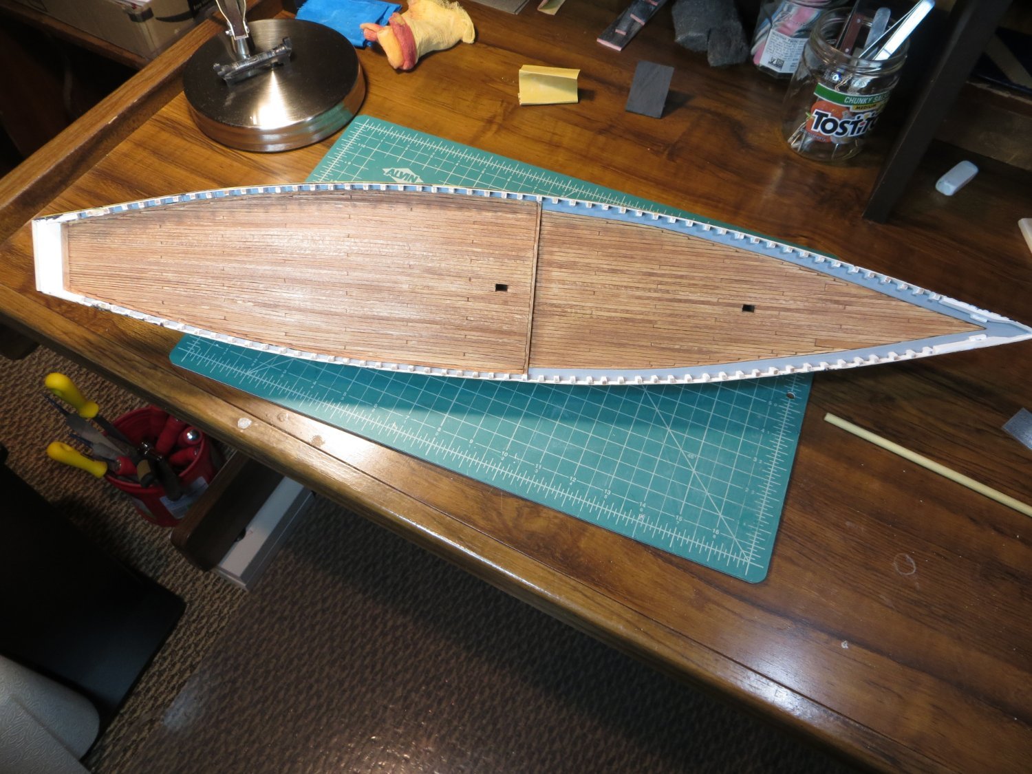
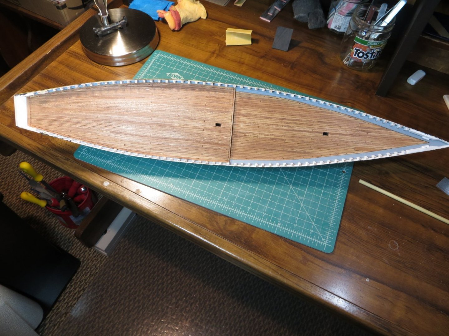
Originally posted Oct. 29, 2020 Deck Planking I completed planking the deck today. This took most of the month of October. I found the nibbing to be the most difficult task. Inserting the final plank on each side was also a challenge. But, I think it turned out pretty well for my first time. The next major step will be painting the hull. I plan on using an airbrush that I purchased for this build. Except for doing the waterway, I've never airbrushed before. I had difficulty with lots of goobers in the paint. I've since repainted them several times with a regular brush. I bought some Vallejo Air paint for the hull painting. You guys seem to think it's pretty easy and smoother than brushing, so, I'm going to do it too.
- 96 replies
-
- 6
-
-
- model shipways
- bluenose
- (and 1 more)
-
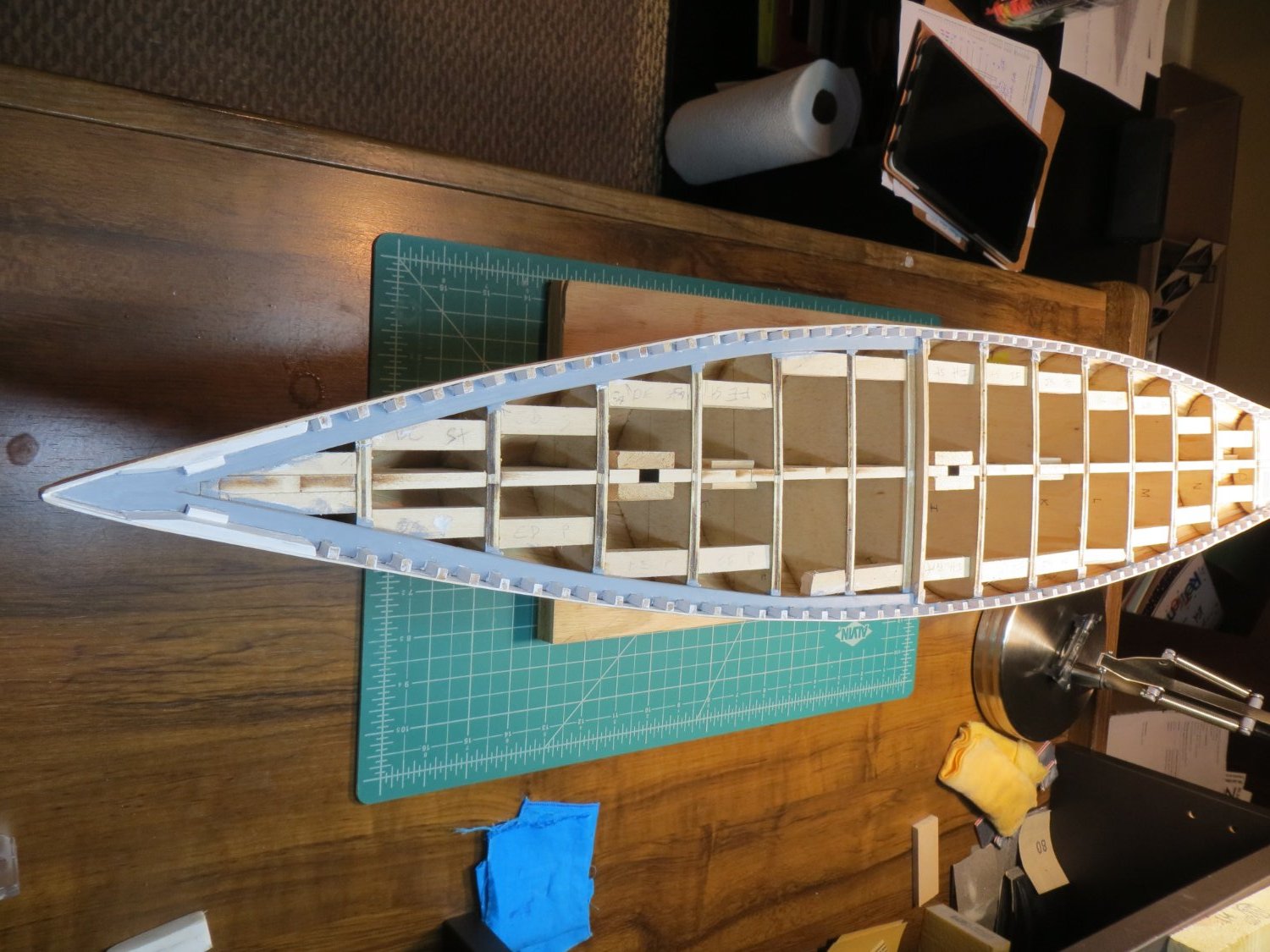
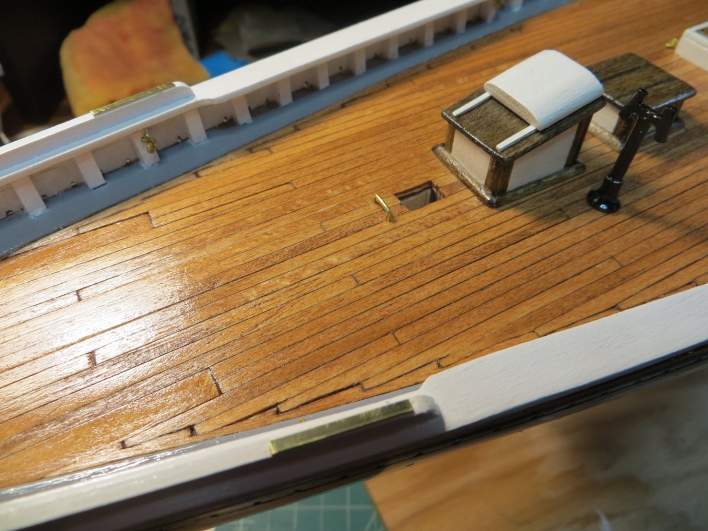
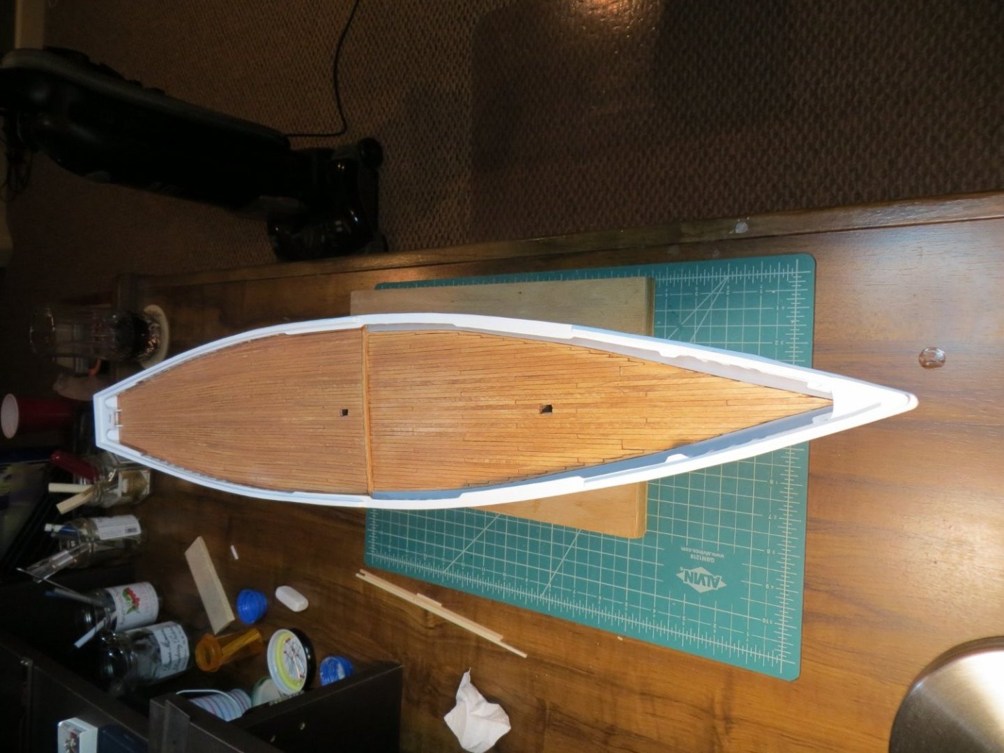
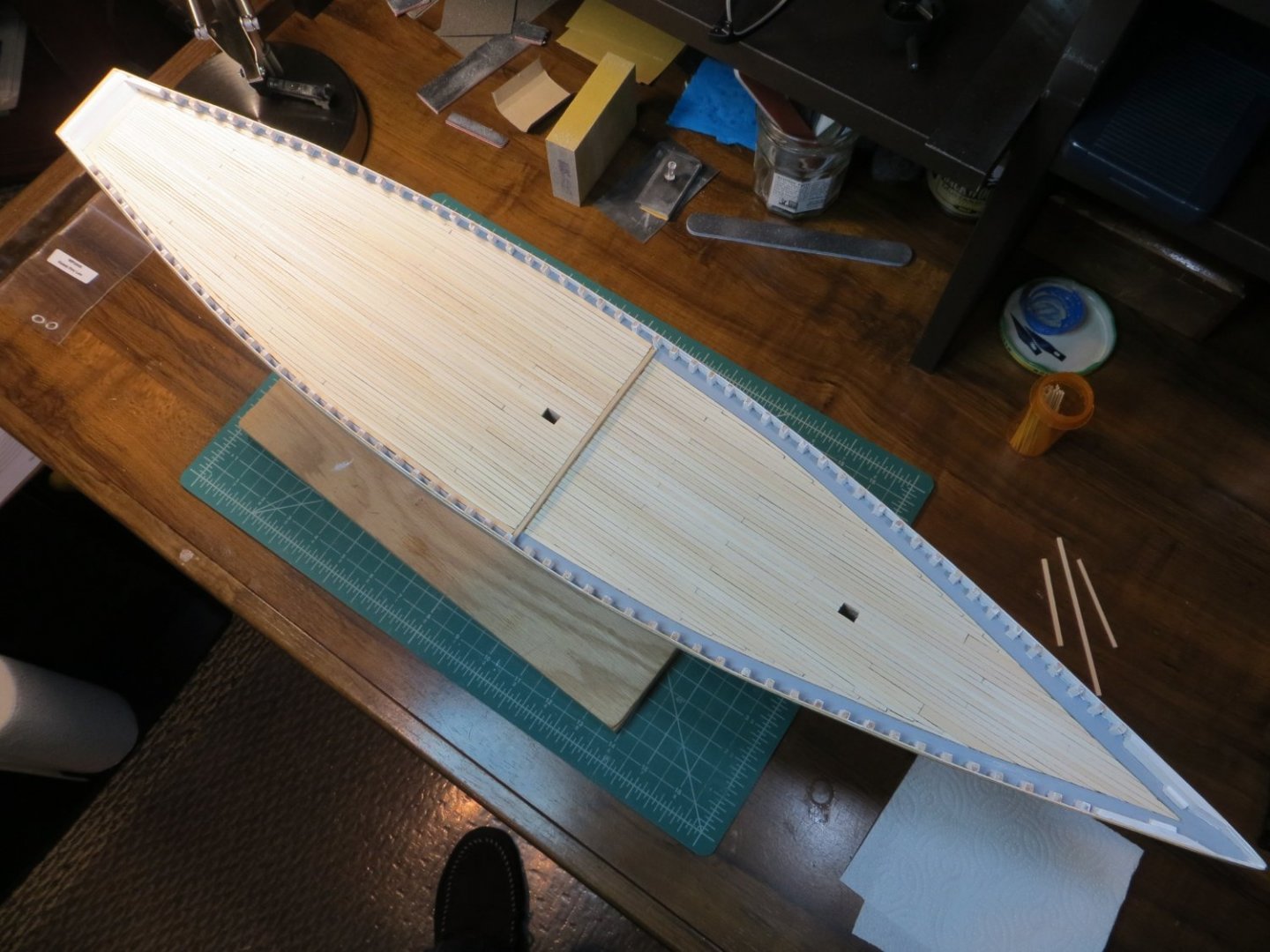
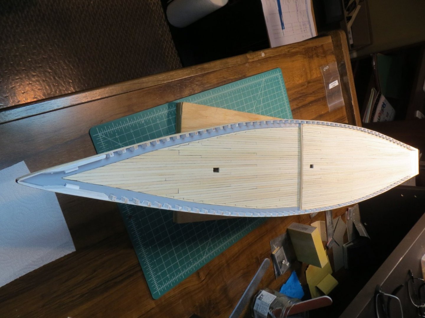
Originally posted on Oct. 1, 2020 Since my last post, I removed all of the bulkhead stanchions and smoothed down the waterway with some heavy sanding. I was not happy with the way it looked after building it last month. I think it looks much better now. I glued in all the stanchions using CA glue. I followed the process I found on the build log from CPDDET. Thanks Dave, your procedure worked great! I cut the scuppers and attached these bulwark planks including the waist plank. While these were exposed, I painted the waterway light grey and the inner bulwarks white. I also planked the transom, inside and out. These are photos from this point taken today. The next step is planking the deck. I am following the process from Suburban Ship Modeler. He inserted butt joints using a staggered pattern across the bulkheads of 1,3,5,2,4. Although more difficult, I think this looks a little more realistic then running planks the full length of the deck. There is a tutorial on this process here: http://modelshipworldforum.com/resources/Framing_and_Planking/Deck_PlankingIIbuttshifts.pdf

- 96 replies
-
- 4
-
-
- model shipways
- bluenose
- (and 1 more)
-
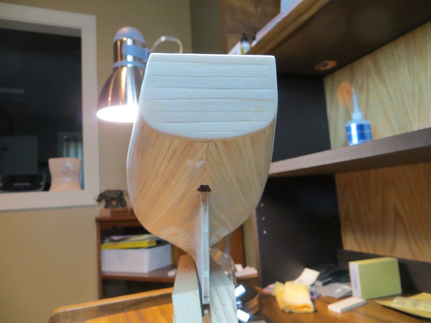
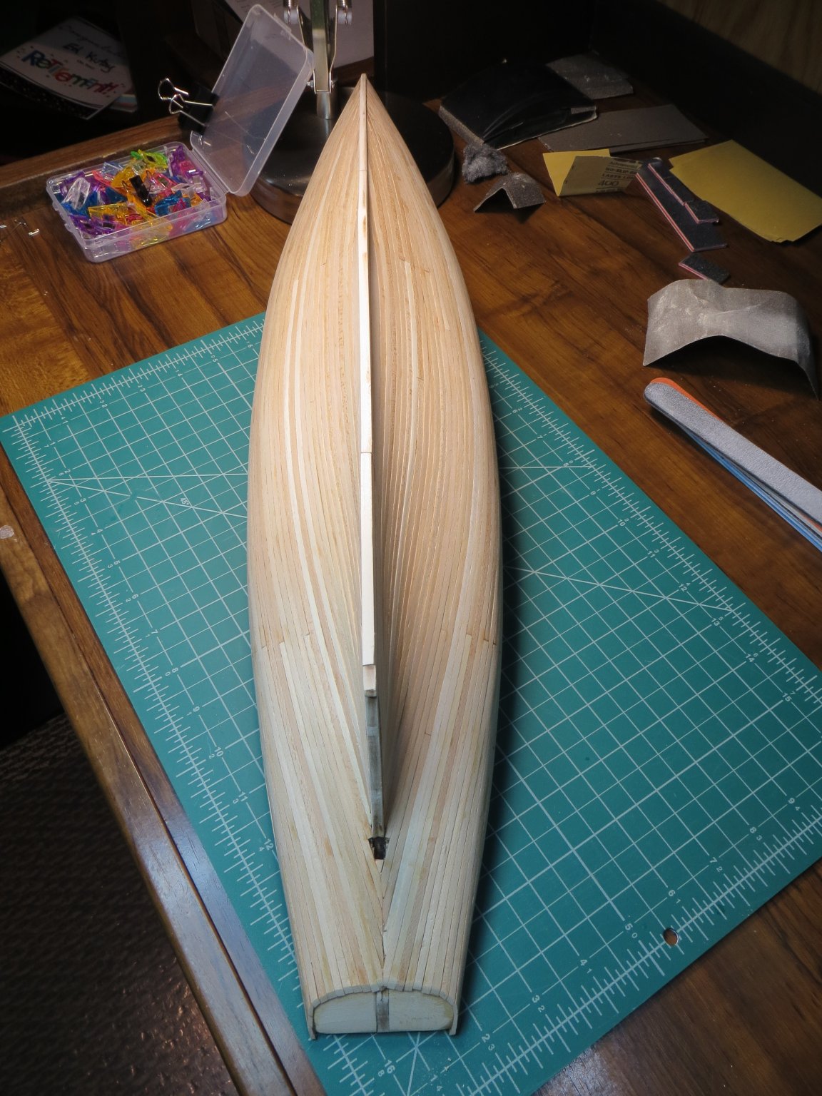
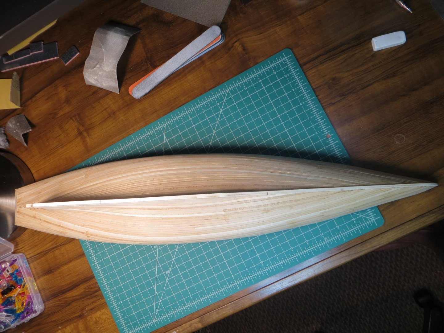
Originally posted on Sept. 6, 2020 Well, I reached a major milestone this week! I completed the planking of the hull. I don't think it turned out too bad for my first time. Here are a couple of pictures of the completed hull before sanding. Next up I will start to work on the sanding and filling of the cracks and gaps. I don't expect to need too much wood filler, but will see how it goes. I will post more pics when I'm done. Do you recommend applying some sanding sealer after sanding is done?

- 96 replies
-
- 5
-
-
- model shipways
- bluenose
- (and 1 more)
-
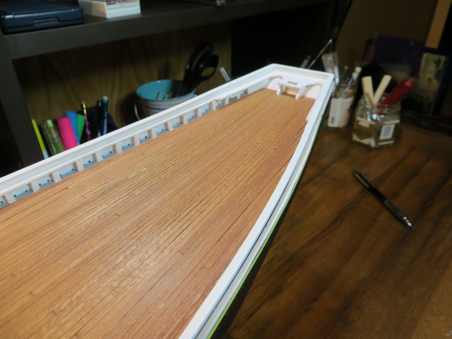
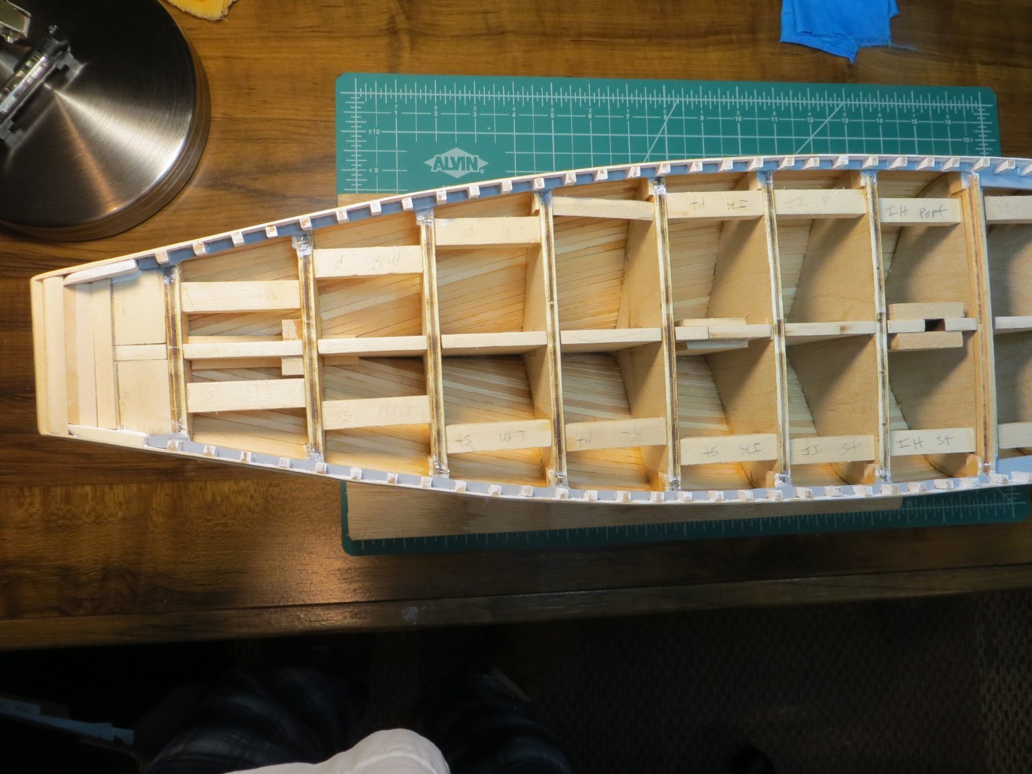
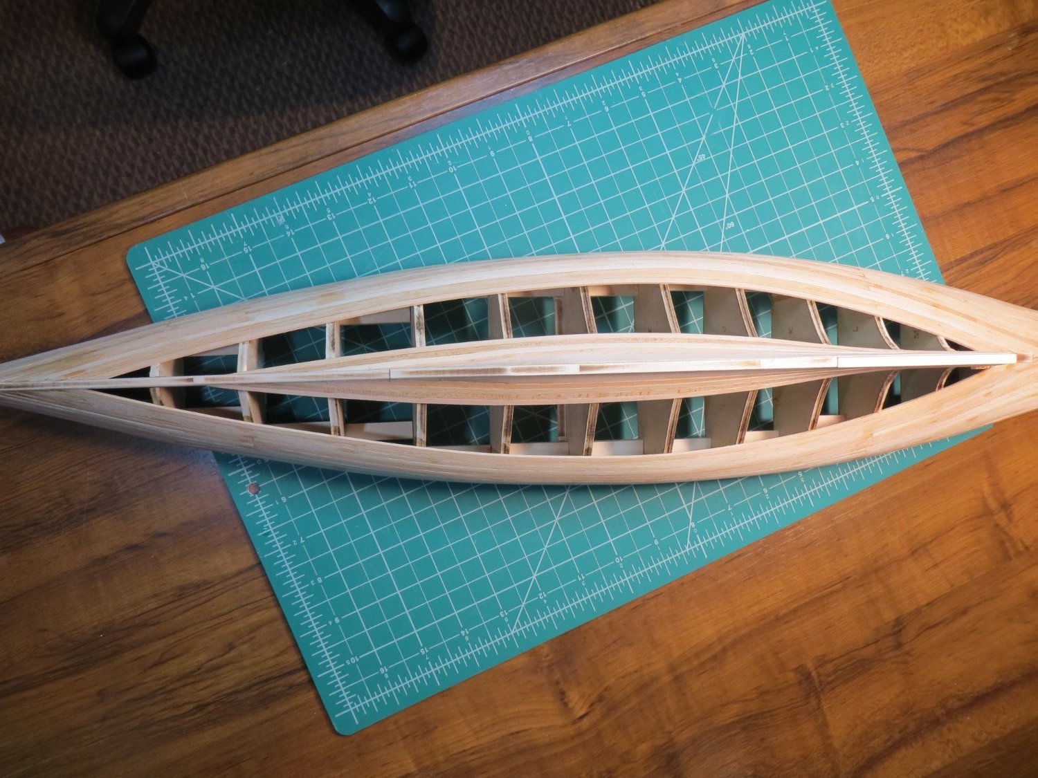
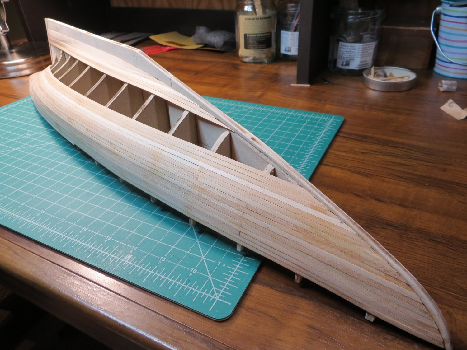
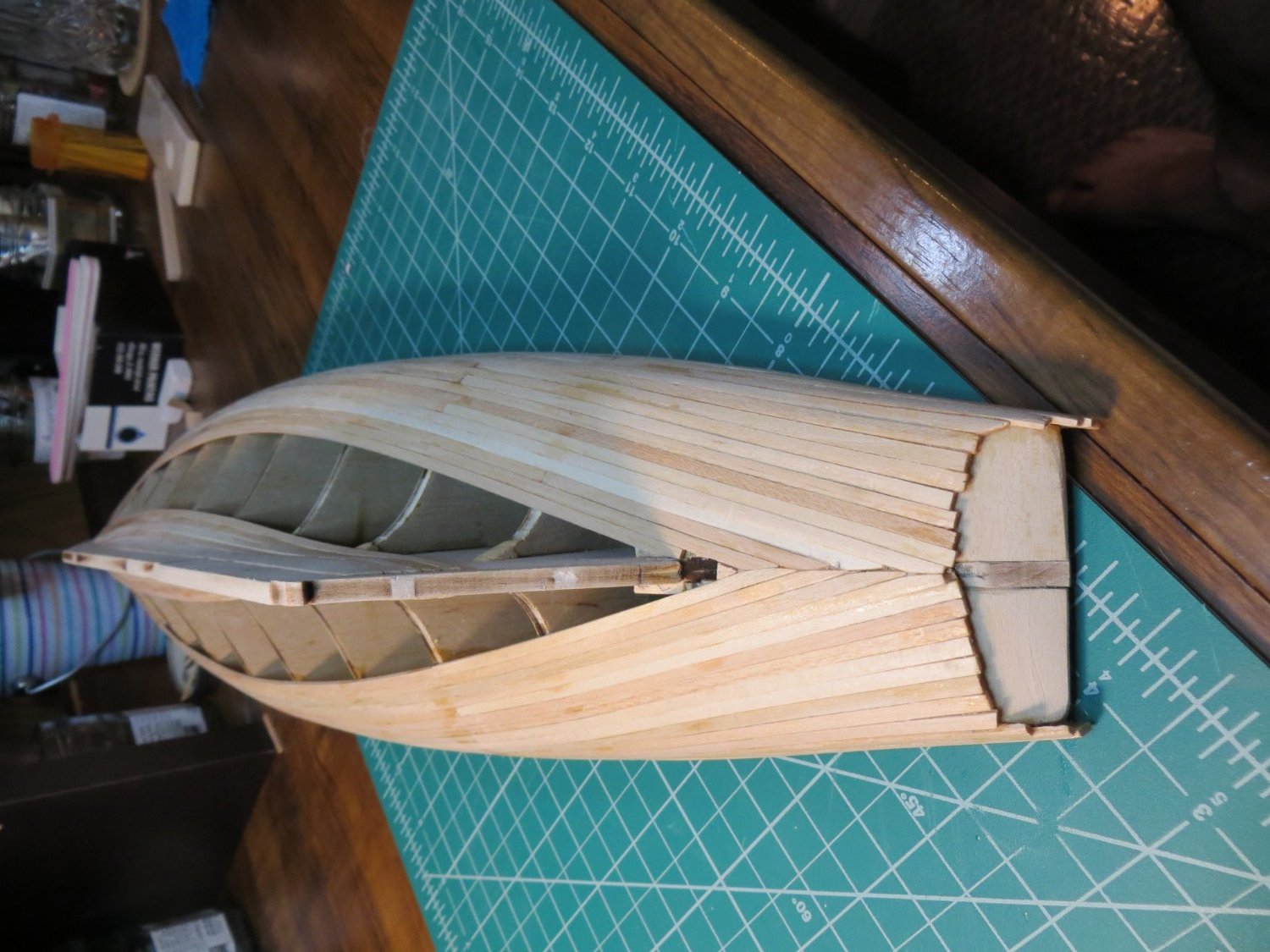
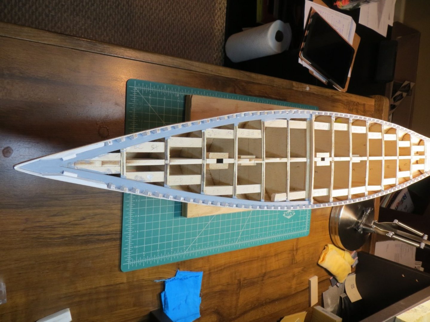
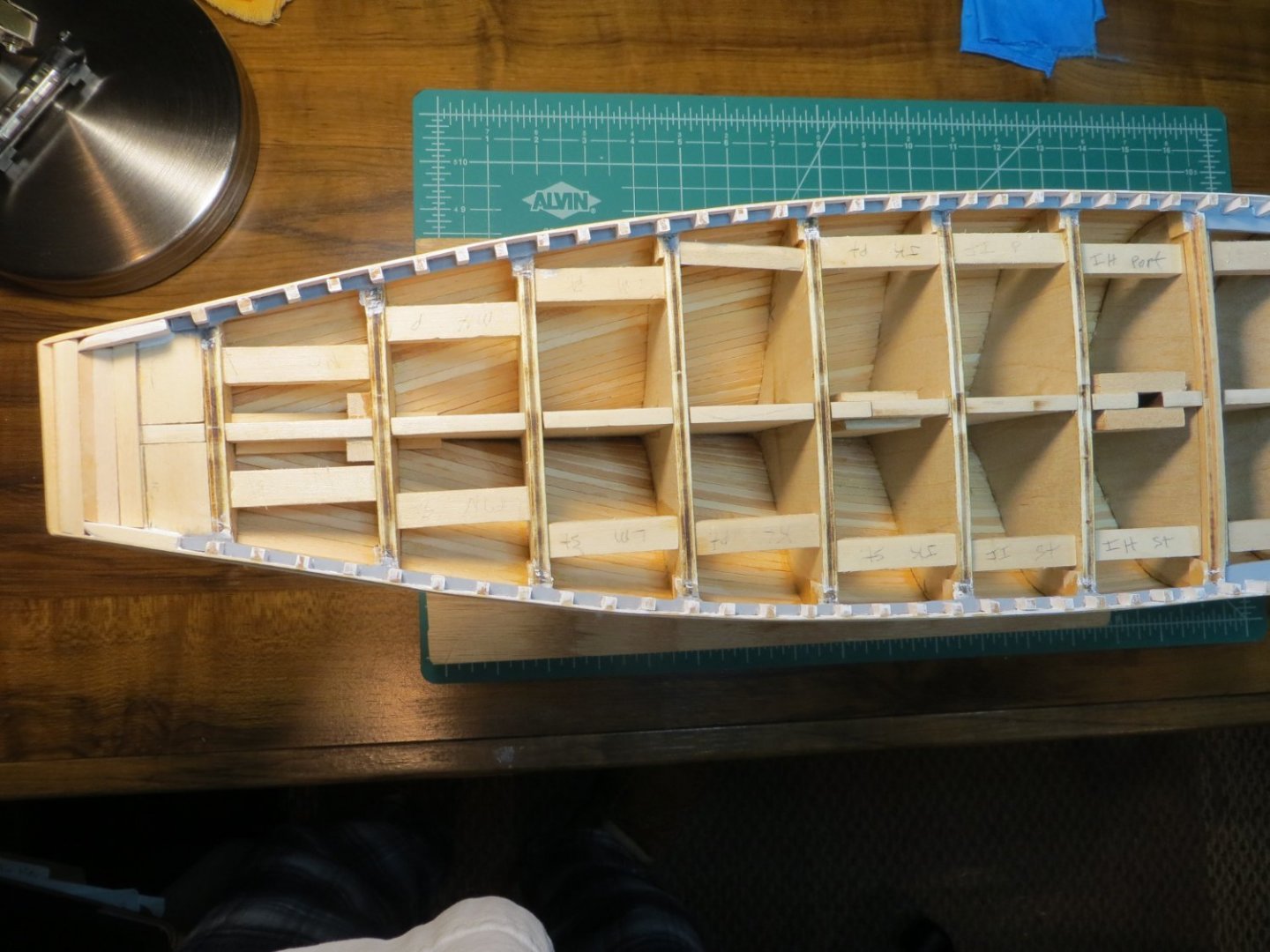
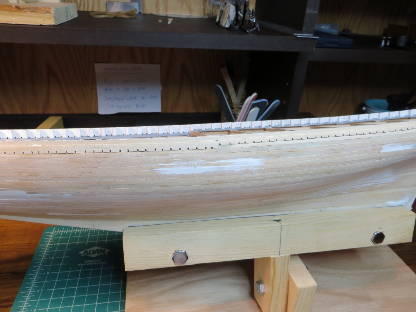
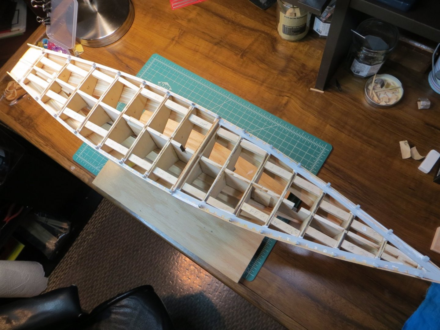
This post was first submitted on August 26, 2020 Planking the Hull The pictures I posted yesterday were taken at the end of July. Since then I've completed the waterway and am in the process of planking the hull. Here are the most current pictures of the progress on the model. Planking is going well. These pictures are before any sanding or filling, so I think I will get it looking pretty good afterward that. I plan on painting the hull as recommended. So I will be able to hide any flaws. I am not satisfied with the waterway. When I complete the hull planking I plan to cleanup the waterway. I would like to remove the bulkhead stanchions and sand down the entire waterway and then install fake stanchions. The spacing between the bulkhead stanchions is uneven, although the bulkheads are all at perfect 90 degree angles with the keel. So, not sure where I went wrong there. (See the last picture of waterway in this post) But, I've read some comments warning not to remove the b/h stanchions until after installing the upper bulwarks. But, it would be much easier to do the cleanup if they are removed first. Then I can use a temporary plank to align all the stanchions. Or maybe leave a few of them for supports to install the bulwark? Has anyone else done this successfully?


- 96 replies
-
- 3
-
-
- model shipways
- bluenose
- (and 1 more)
-
PLEASE NOTE THE FOLLOWING OK! So, after the initial couple of posts on my build log for Bluenose I did something wrong and all of my further postings were done as "Profile Status Updates" (found under Ed Ku20) AND were not attached to this build Topic as intended. I am going to try to correct this problem by copying those updates over to this topic and once done I will delete the other misplaced postings. I don't know if there is an easier way to merge/copy them over, but I'm guessing not. I will insert the original posting date to help keep them straight. I will begin with the post that came after the above.
- 96 replies
-
- 1
-
-
- model shipways
- bluenose
- (and 1 more)
-
-

-
-
Happy New Year to you and yours as well.
Have to say I'm a bit jealous of your work, looks very nice. In this hobby we are all learning as we go.
I'm viewing this, my first build, as a teaching / learning experience. While I'm not really pleased with the product so far, I know my next build will be much better.
Keep up the great work your doing.
-
-