HOLIDAY DONATION DRIVE - SUPPORT MSW - DO YOUR PART TO KEEP THIS GREAT FORUM GOING! (Only 36 donations so far out of 49,000 members - C'mon guys!)
×

Ed Ku20
-
Posts
230 -
Joined
-
Last visited
Content Type
Profiles
Forums
Gallery
Events
Everything posted by Ed Ku20
-
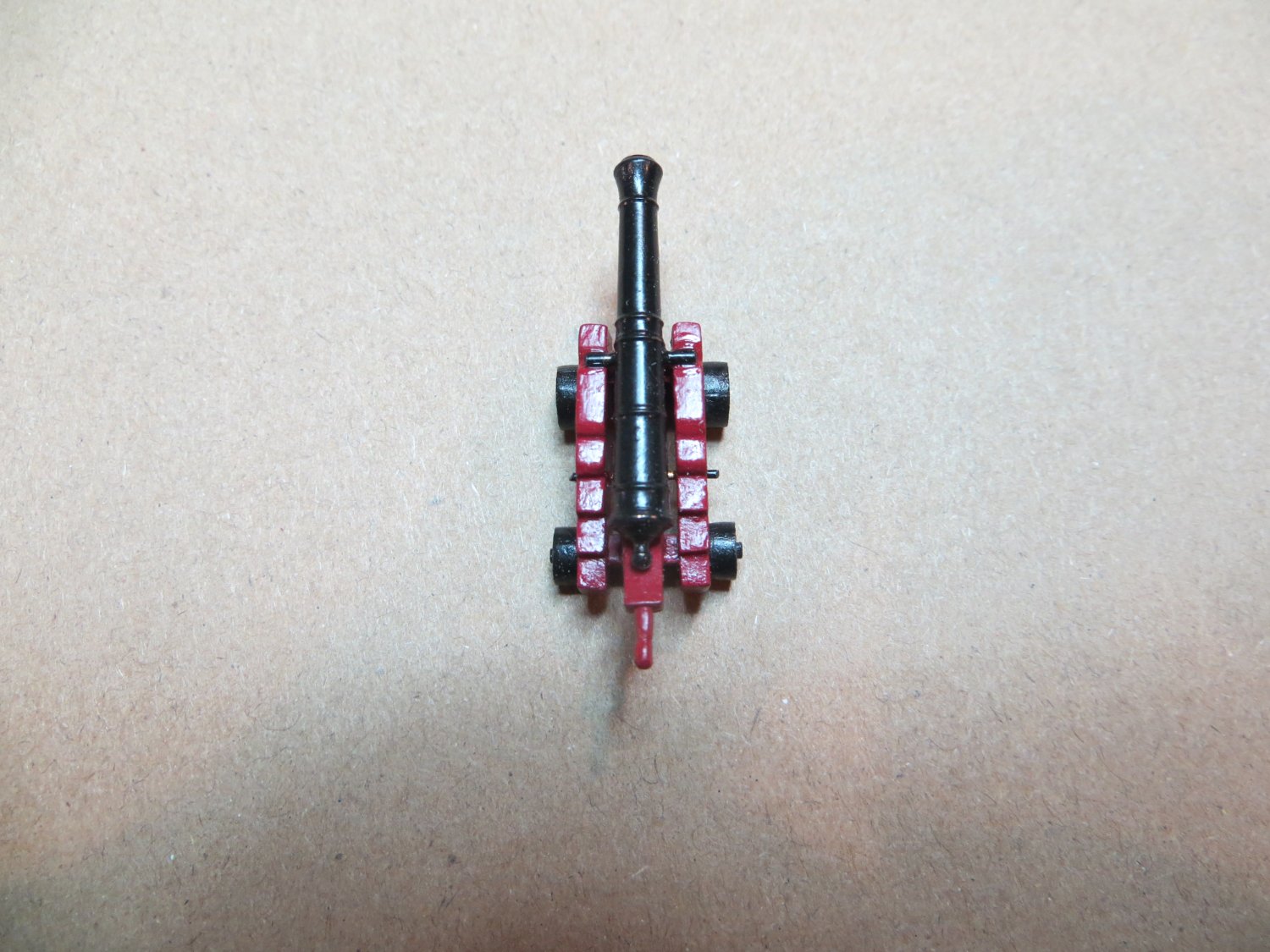
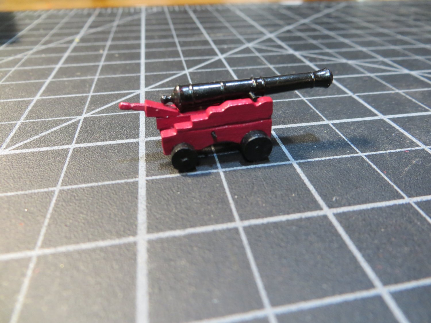
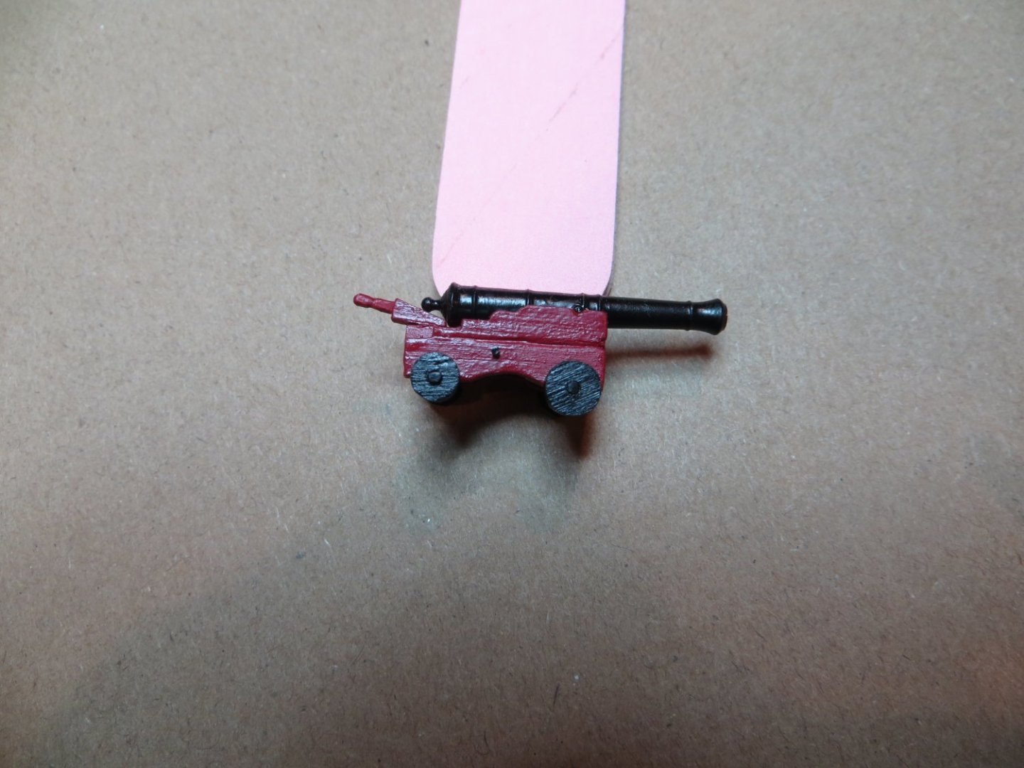
 Allan, it is hard to see even in this picture, but the carriage is definitely built to be wider in the back. There is an angle created by using a shorter axel in the front. Look at the additional space at the sides of the cannon where you can see the rear axel. The trucks (wheels) in the front are also larger then the back, as in your photo.
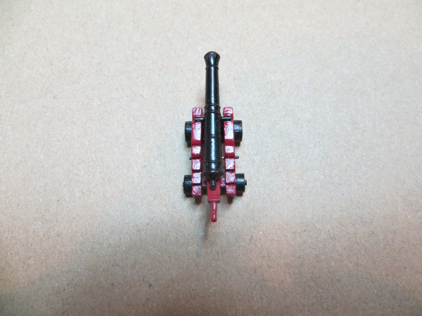
-
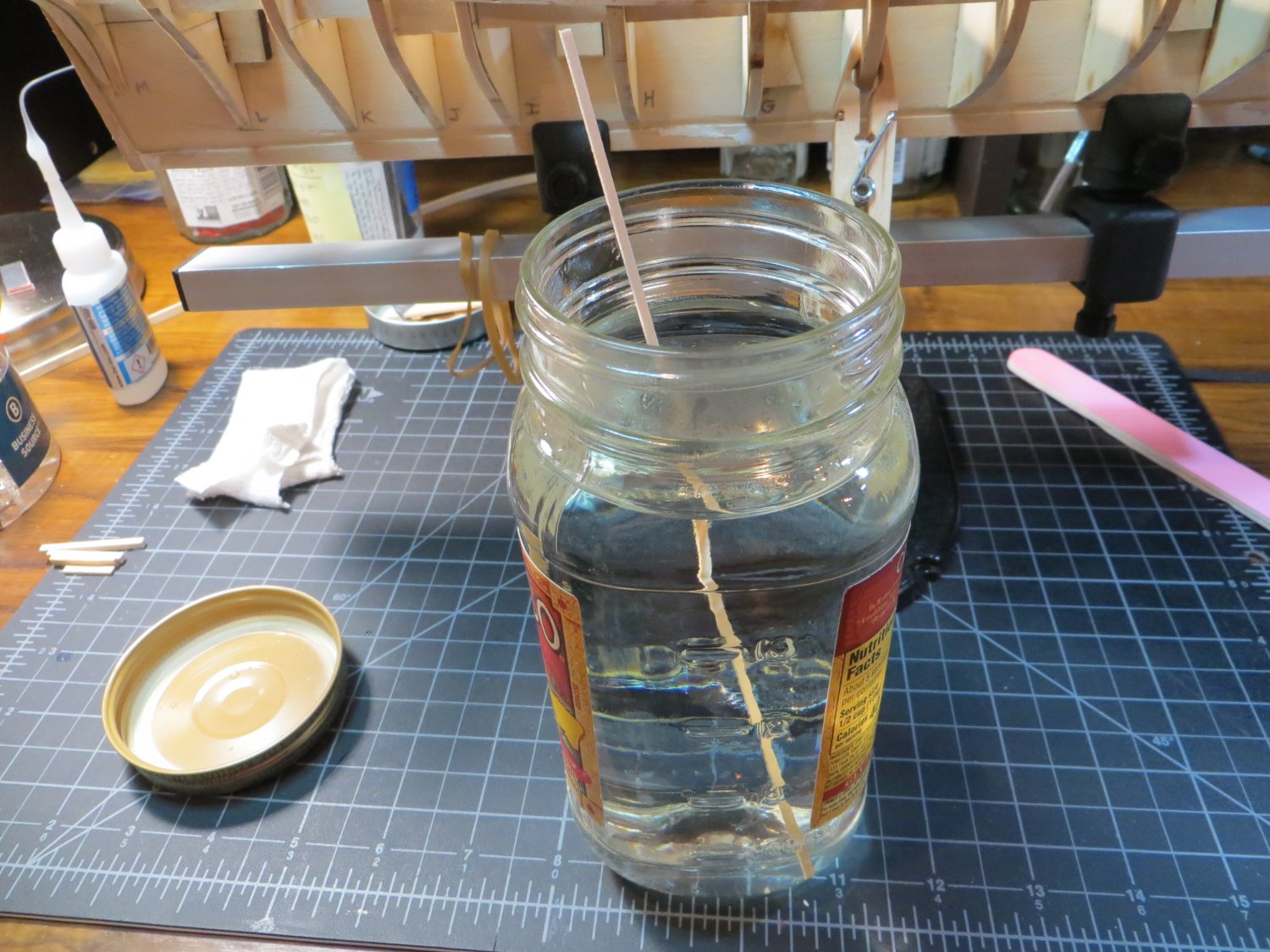
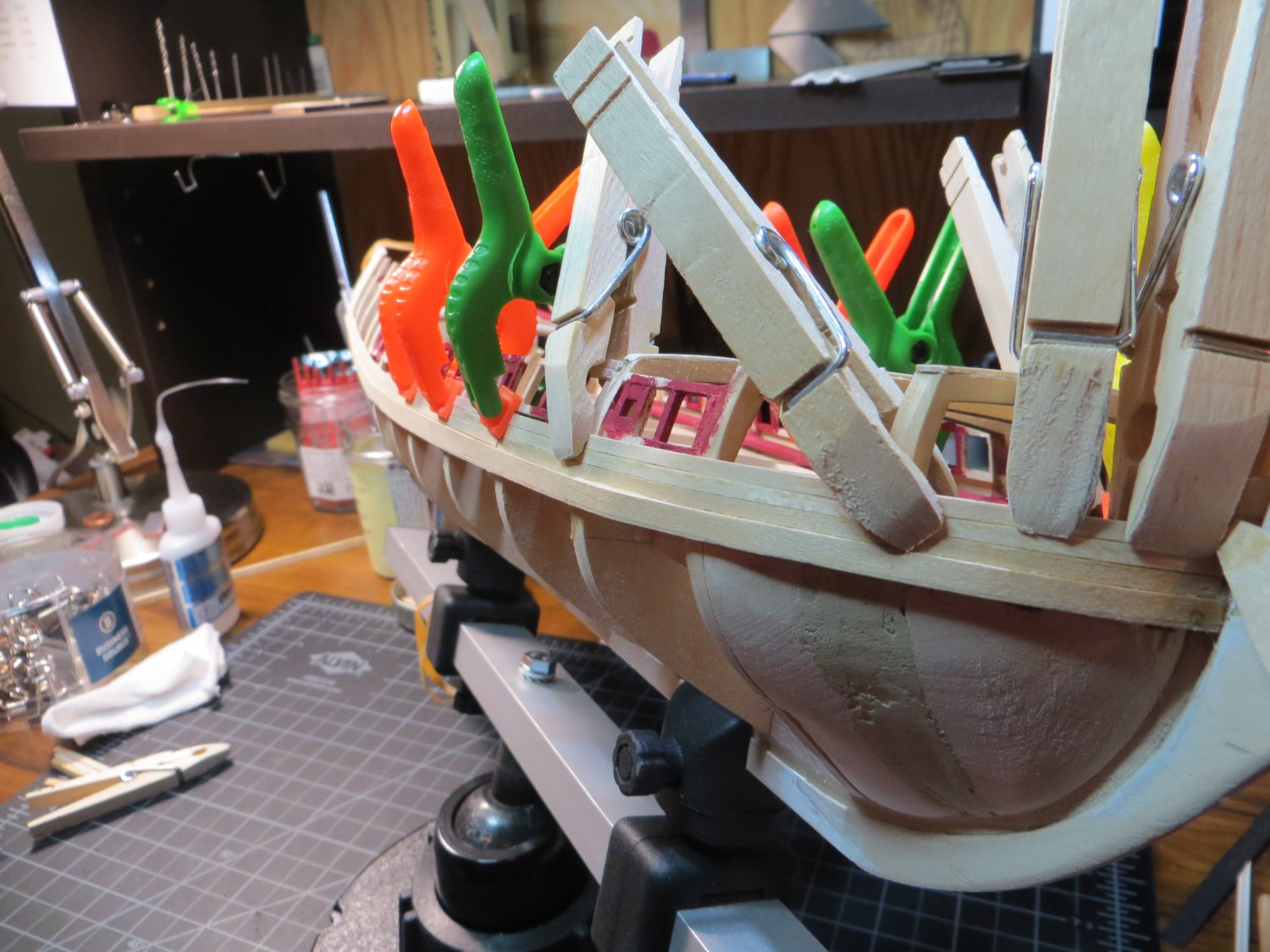
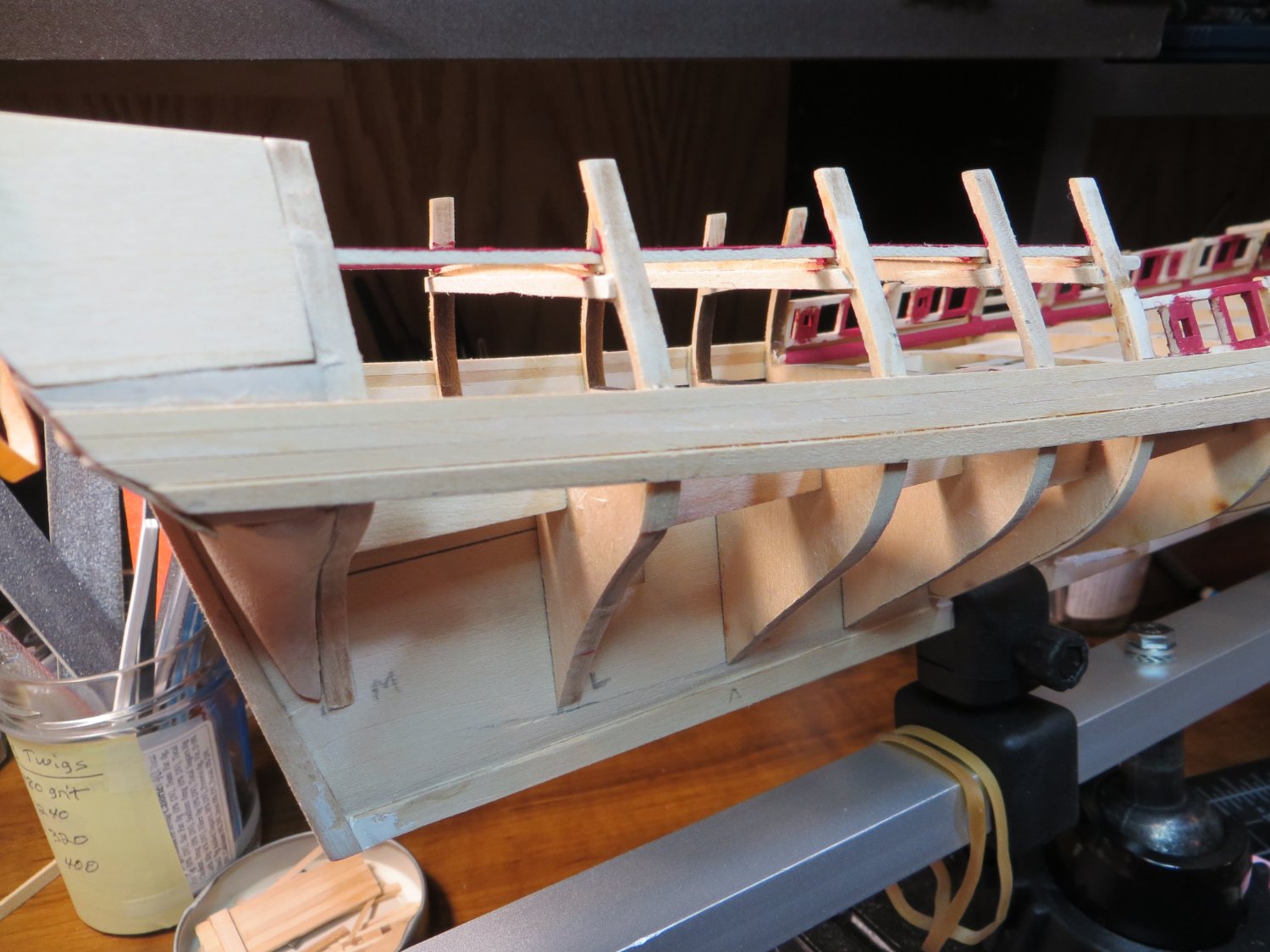
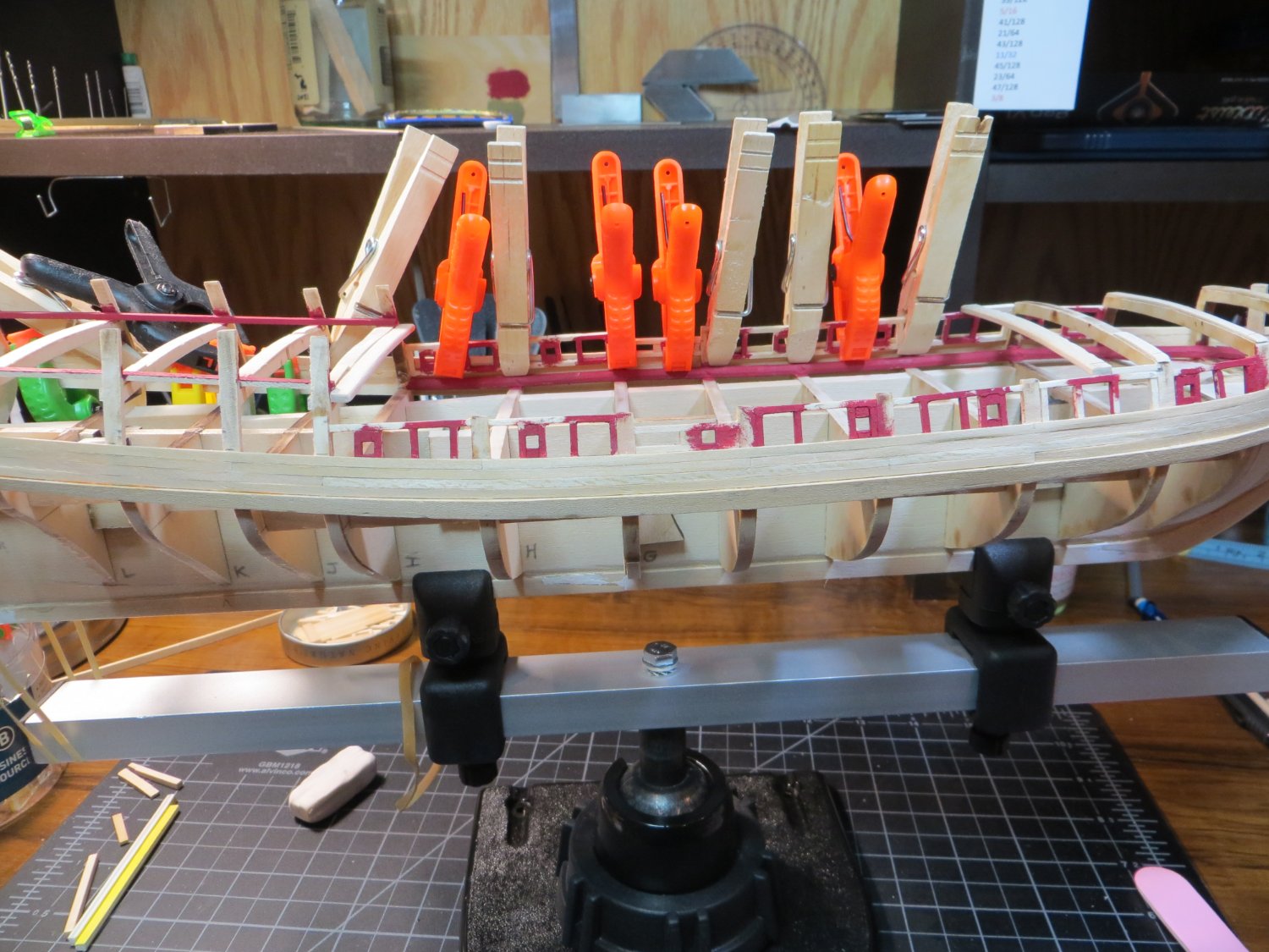
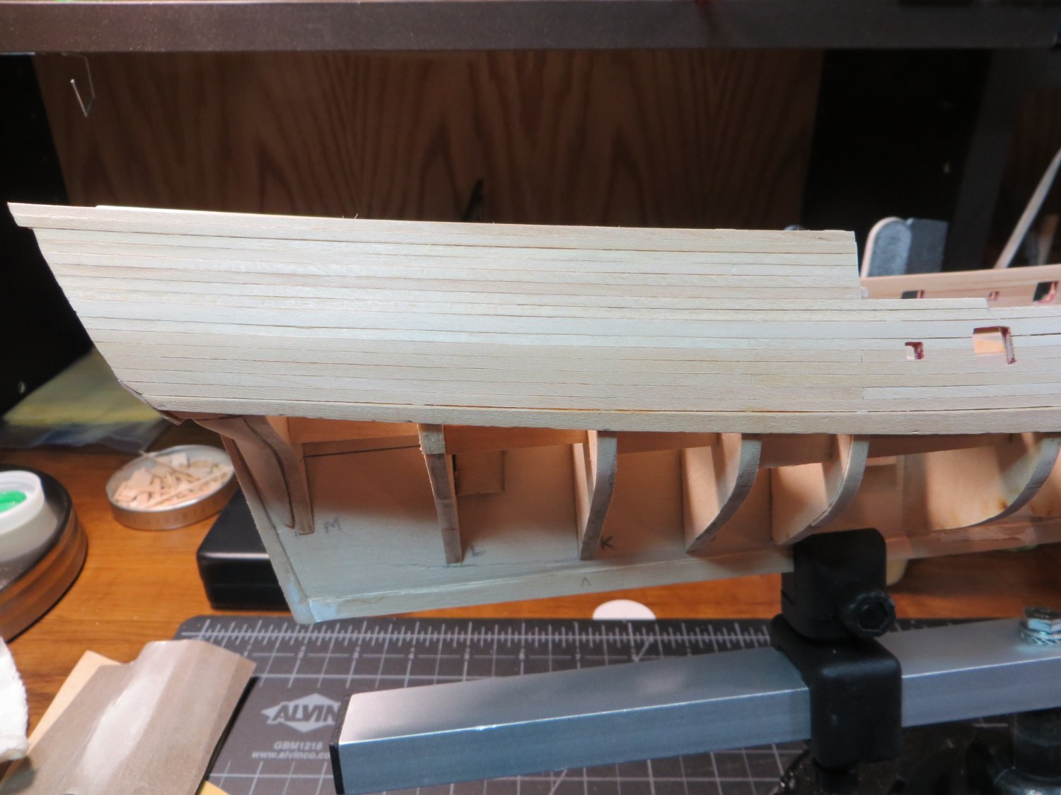
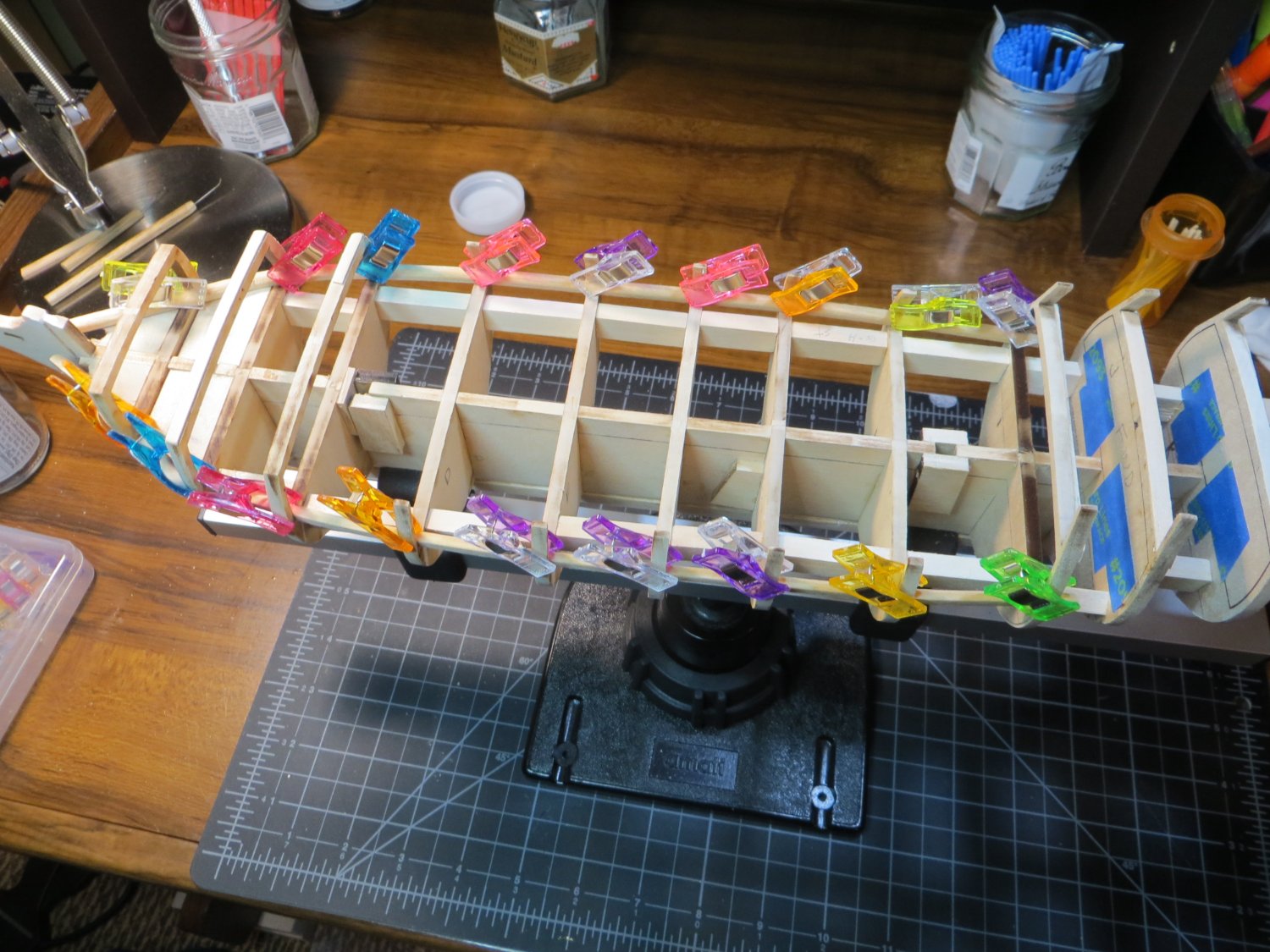
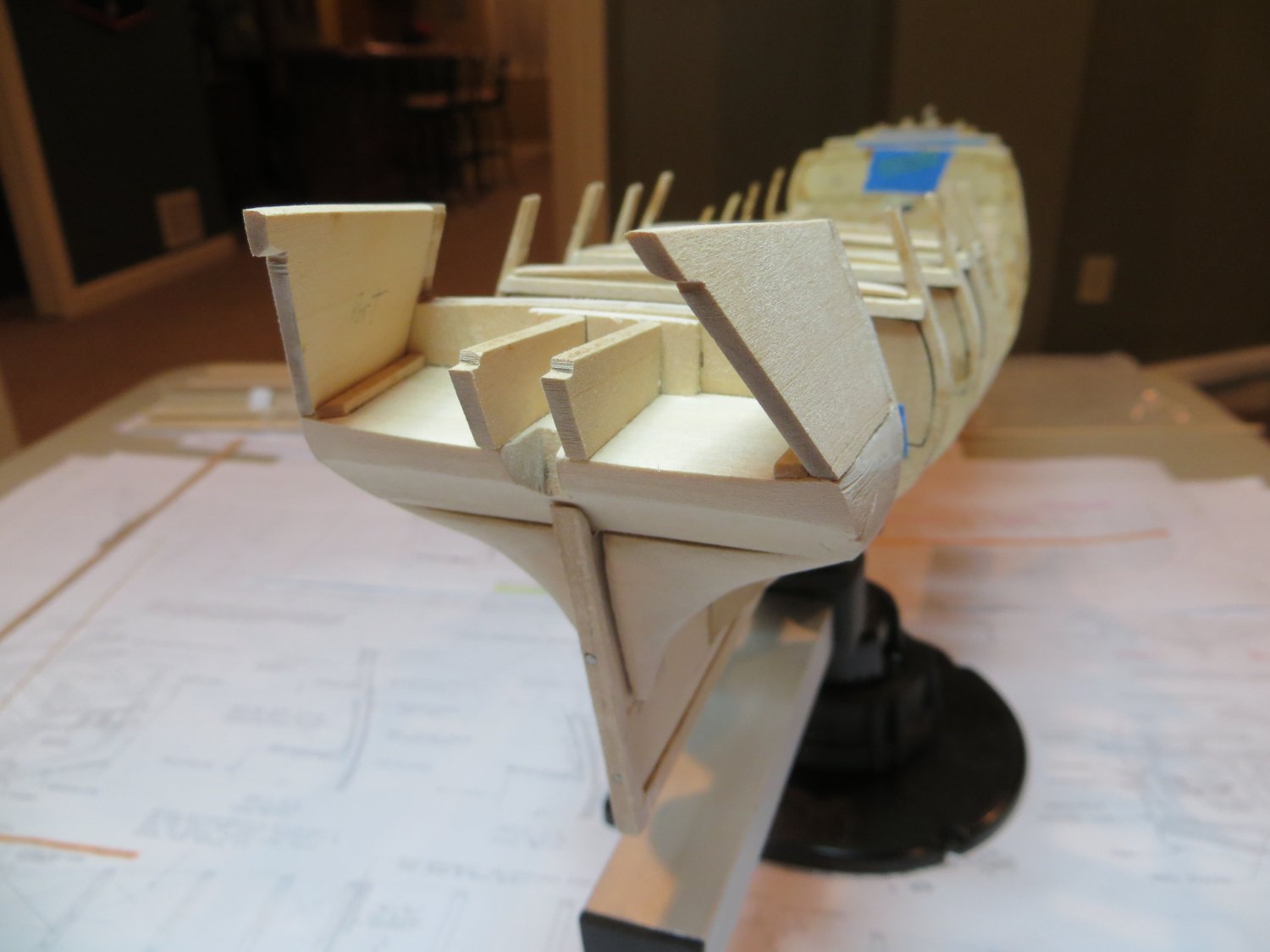
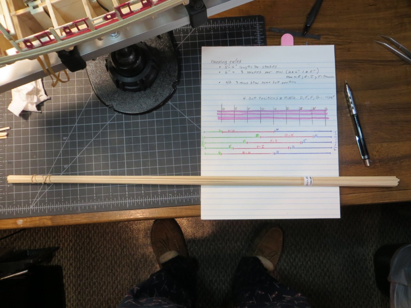
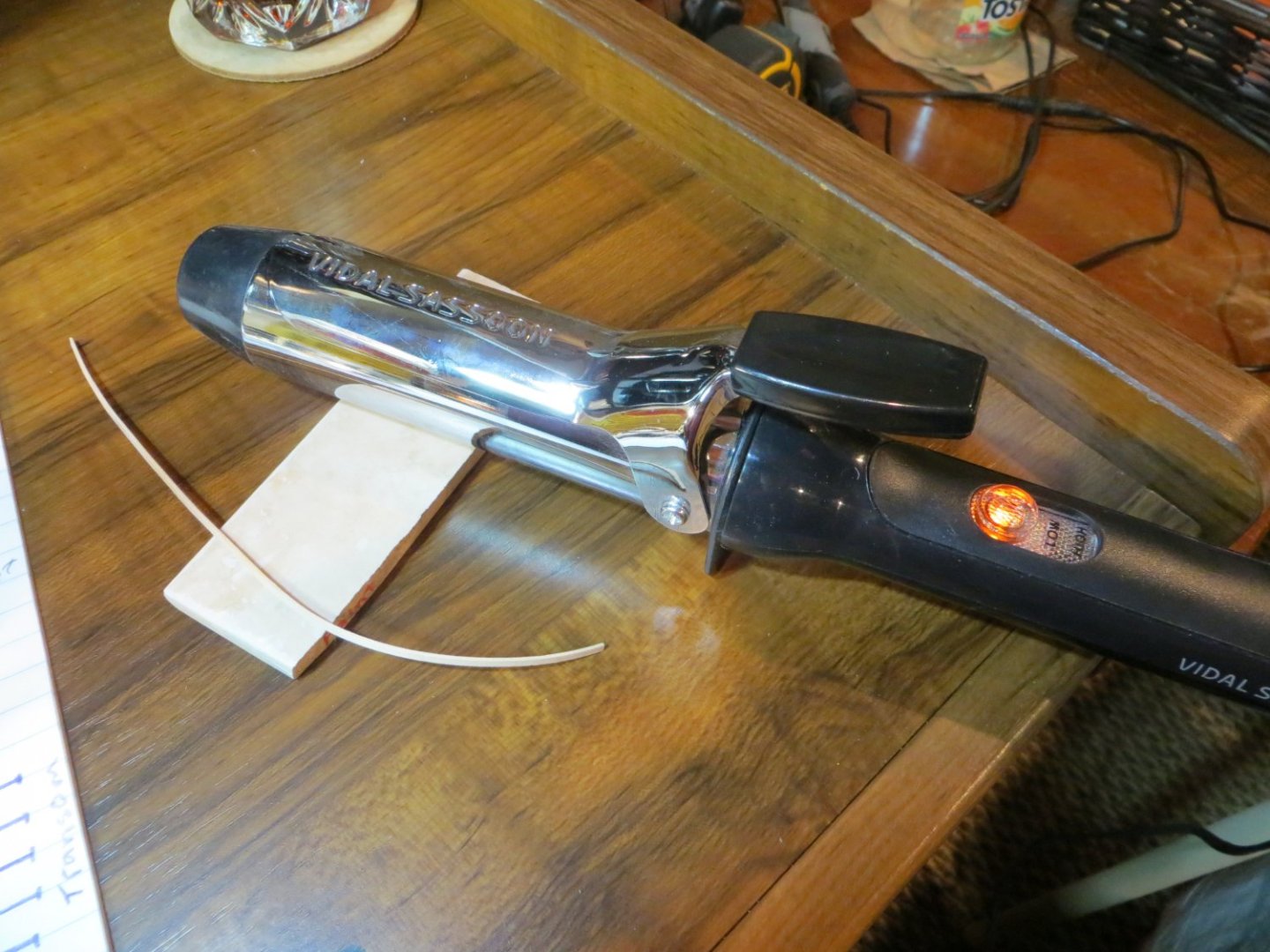
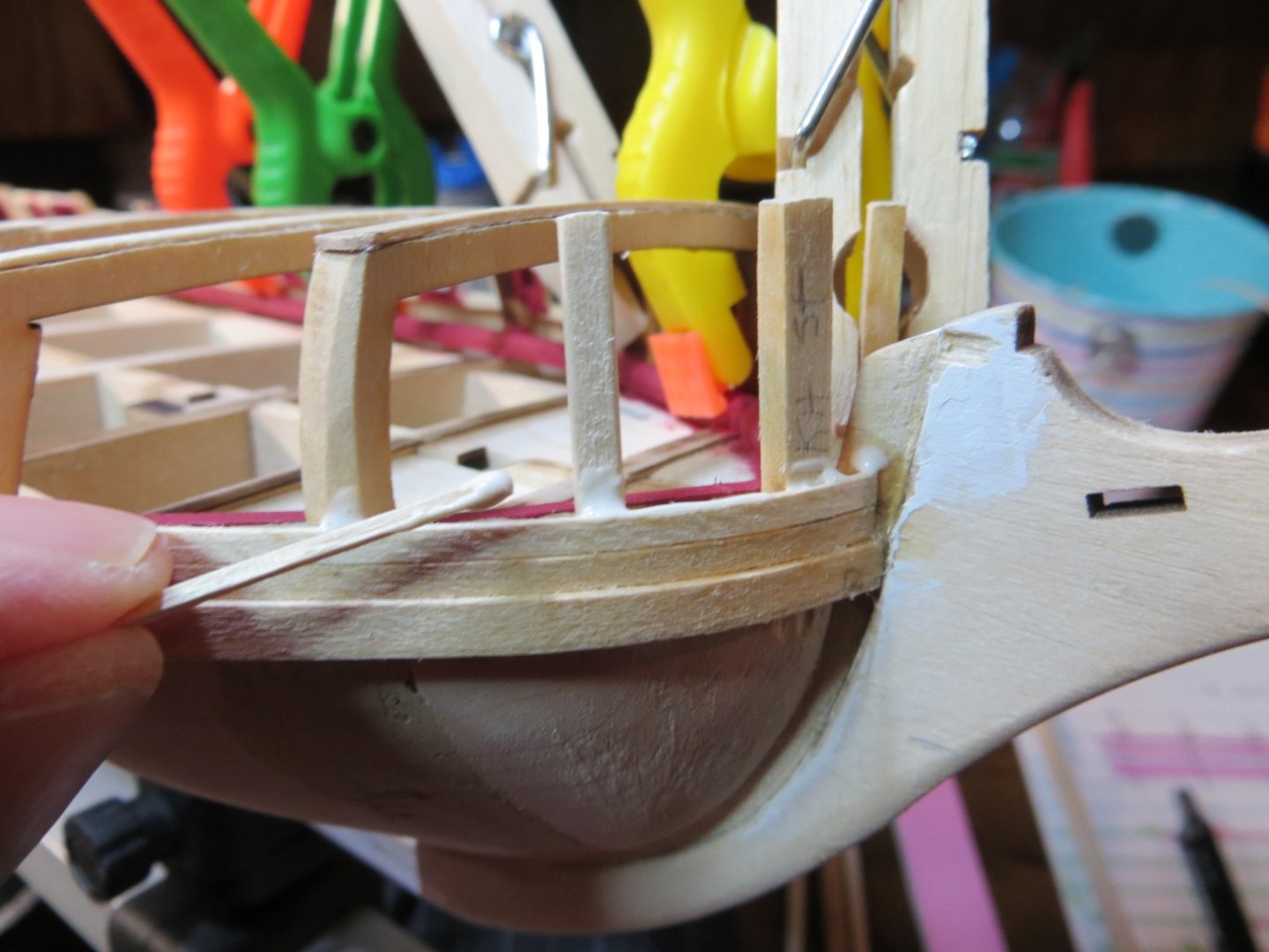
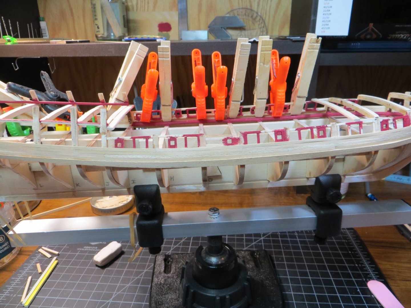
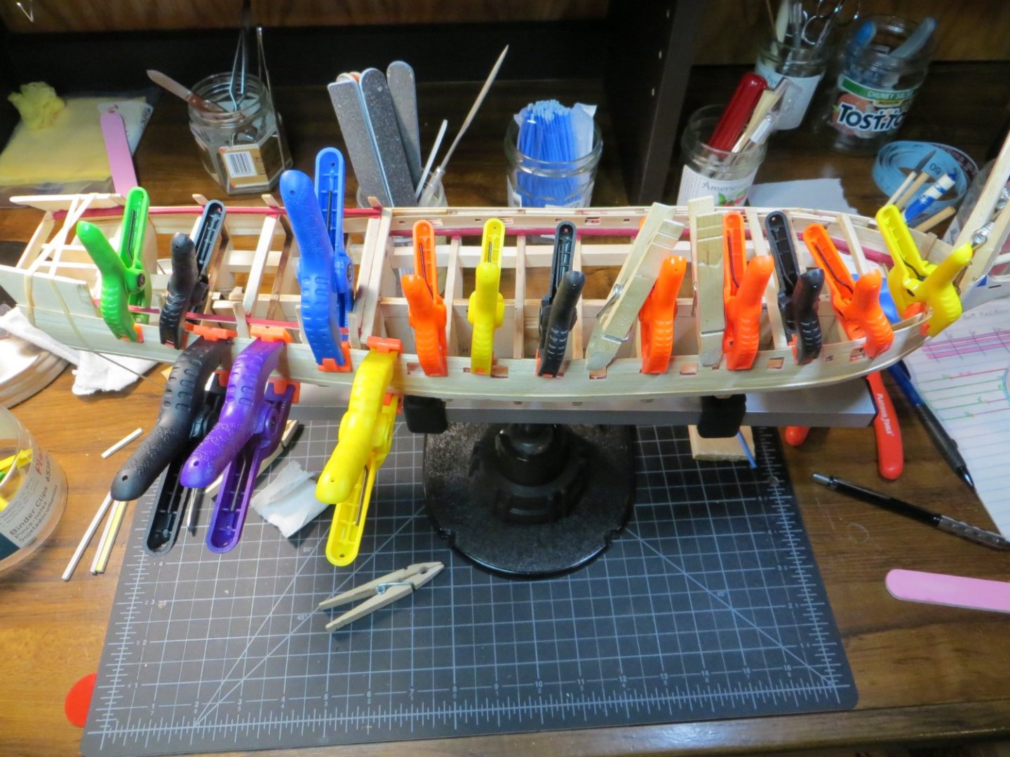
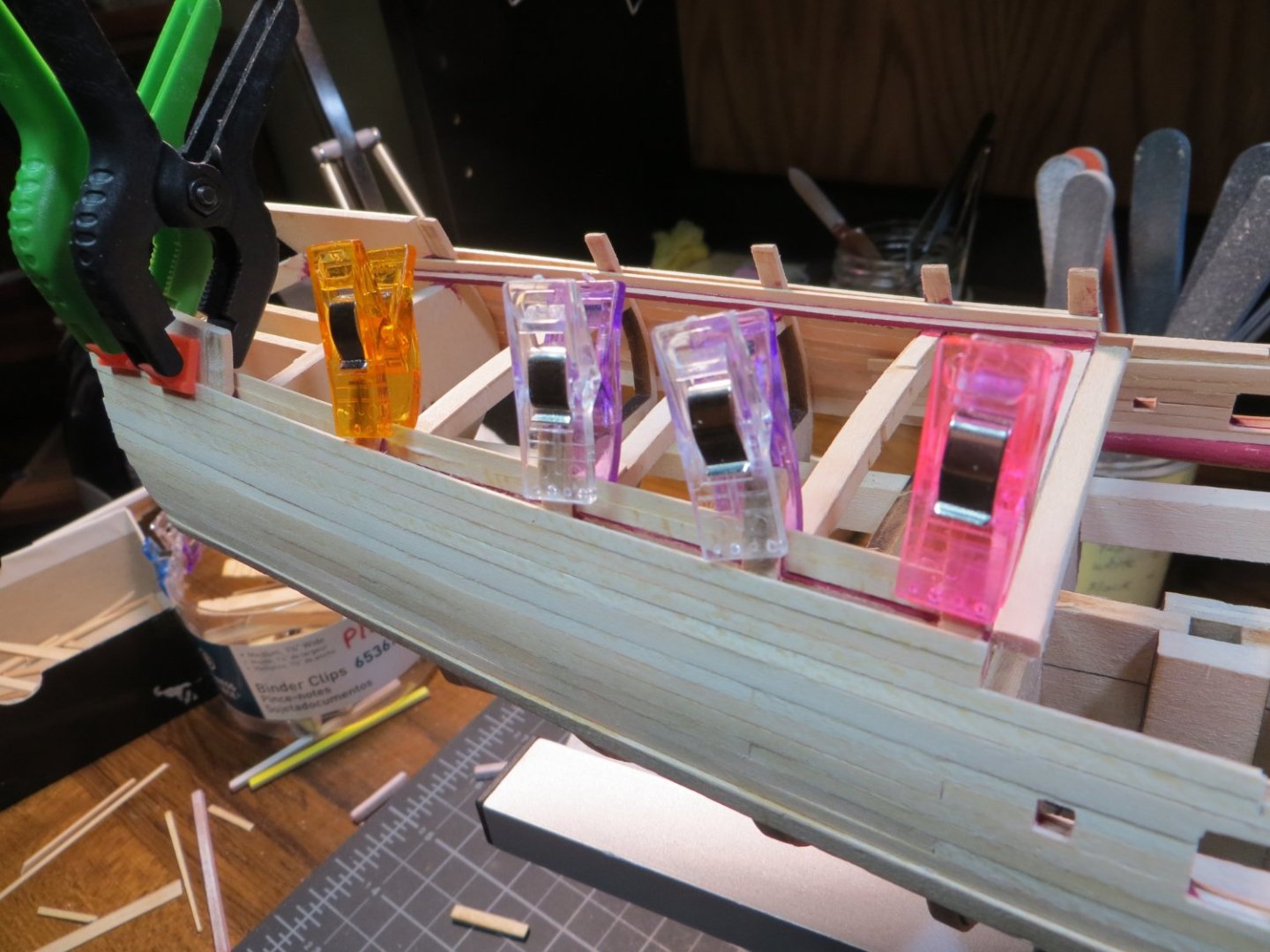
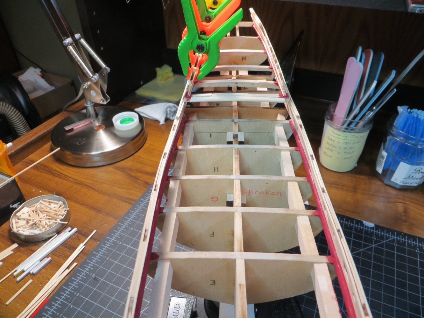
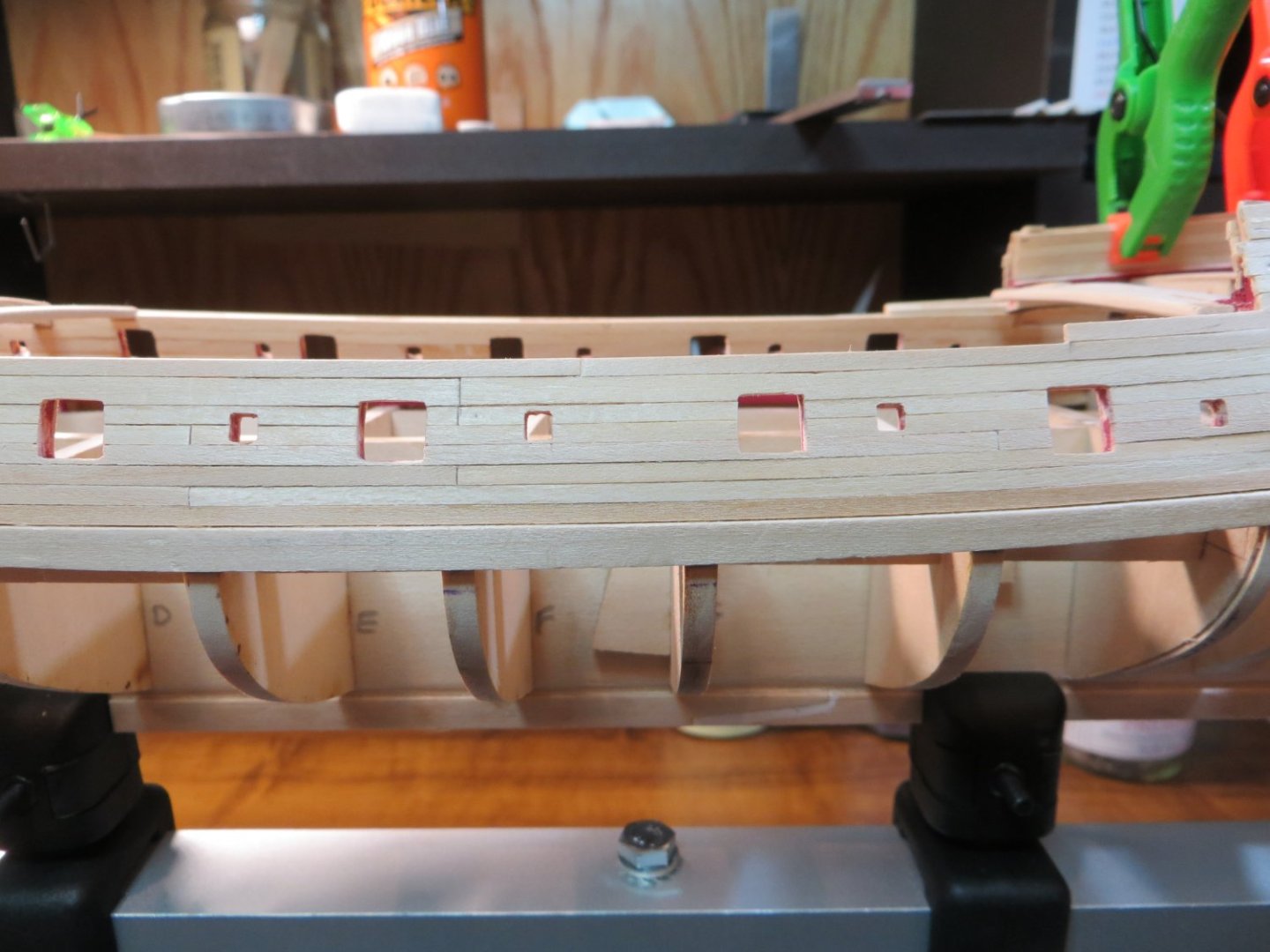
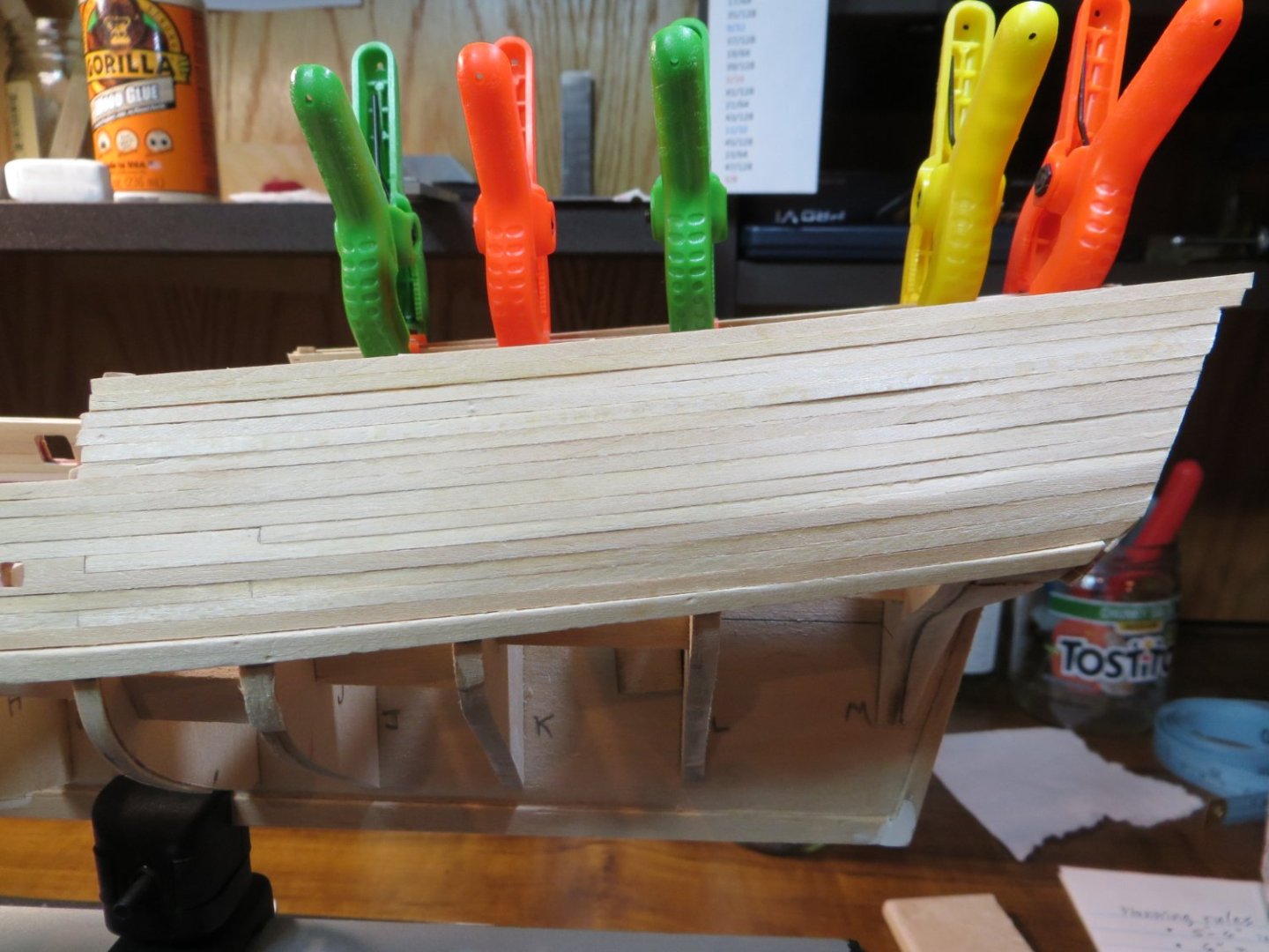
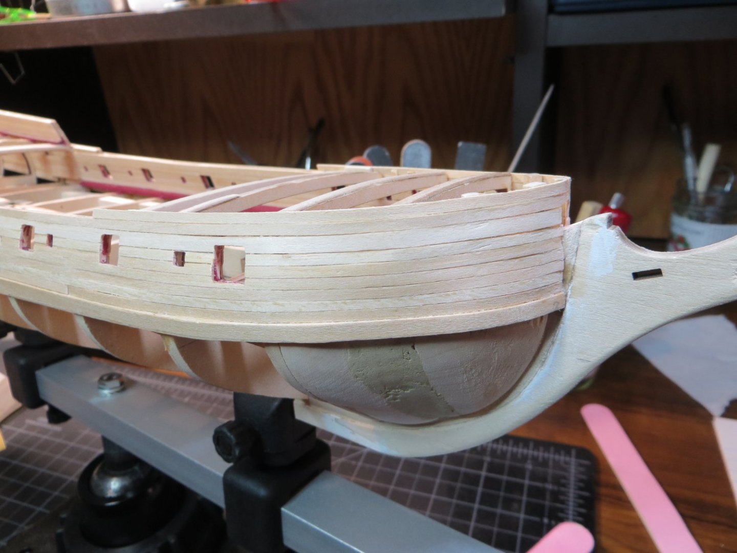
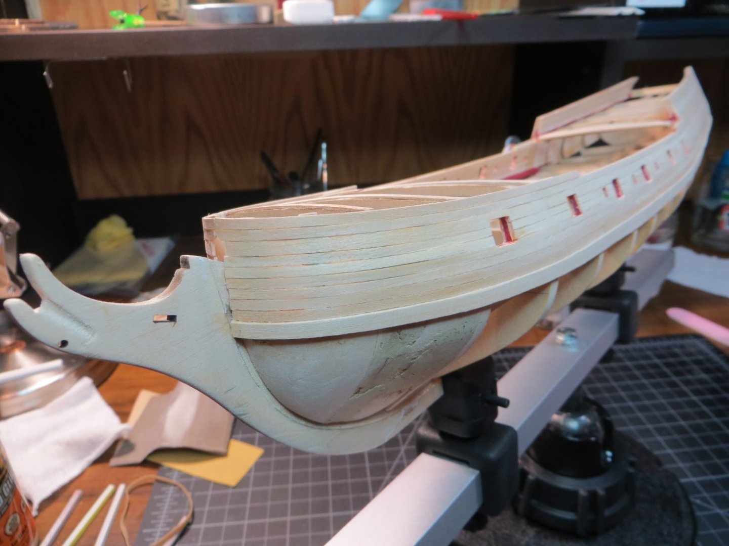
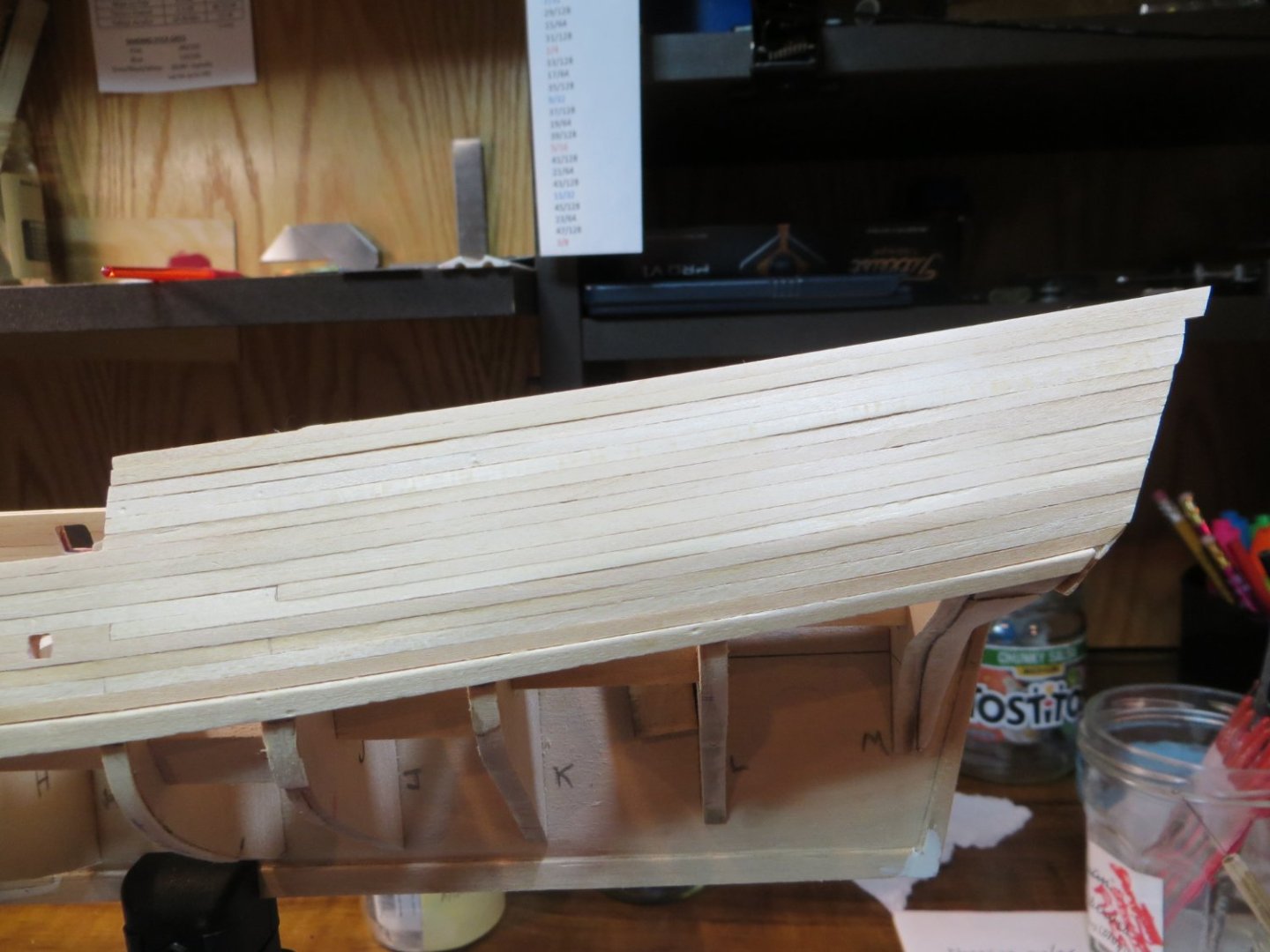
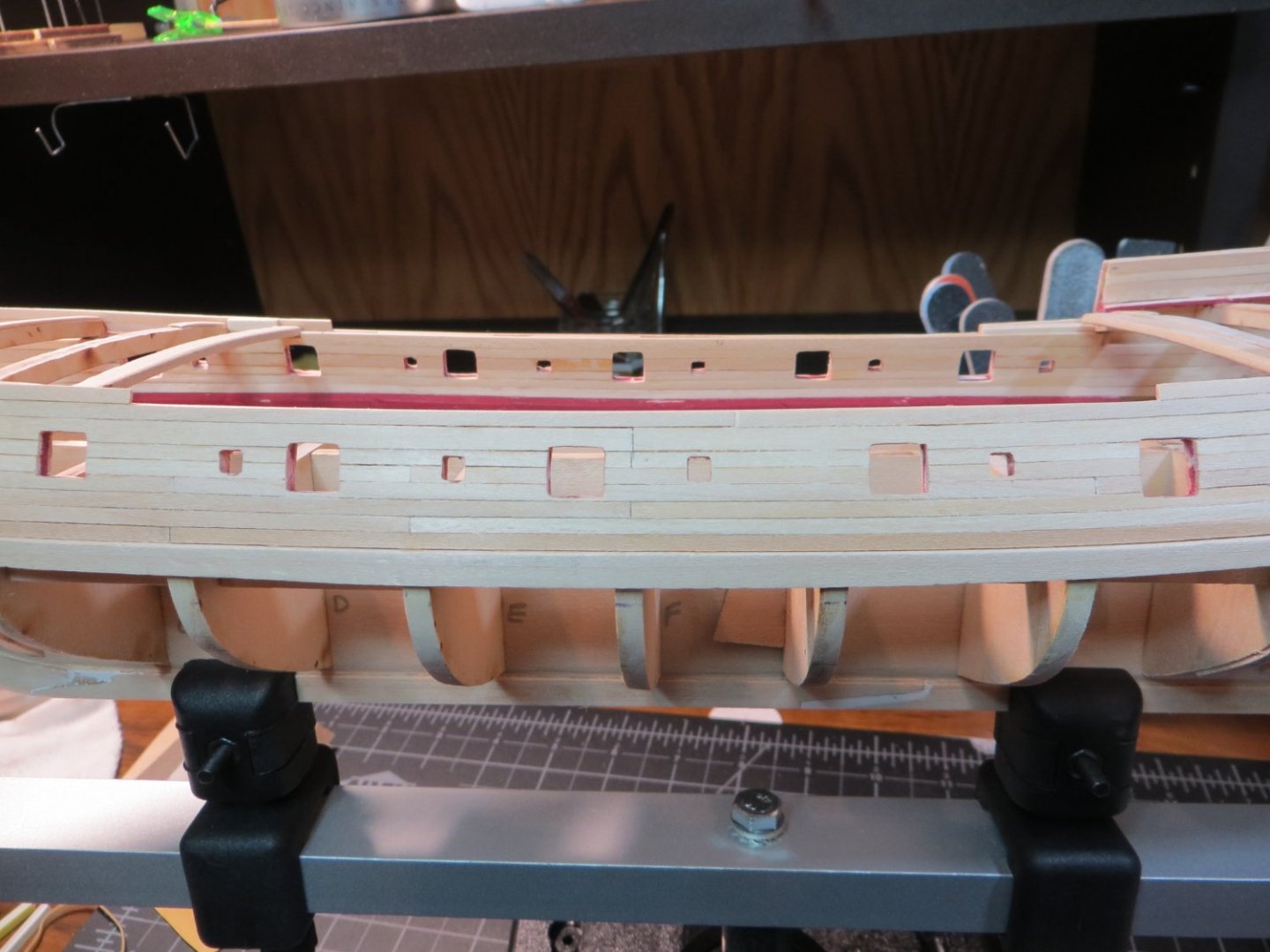
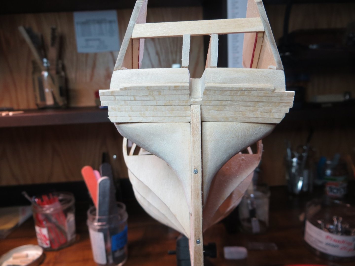
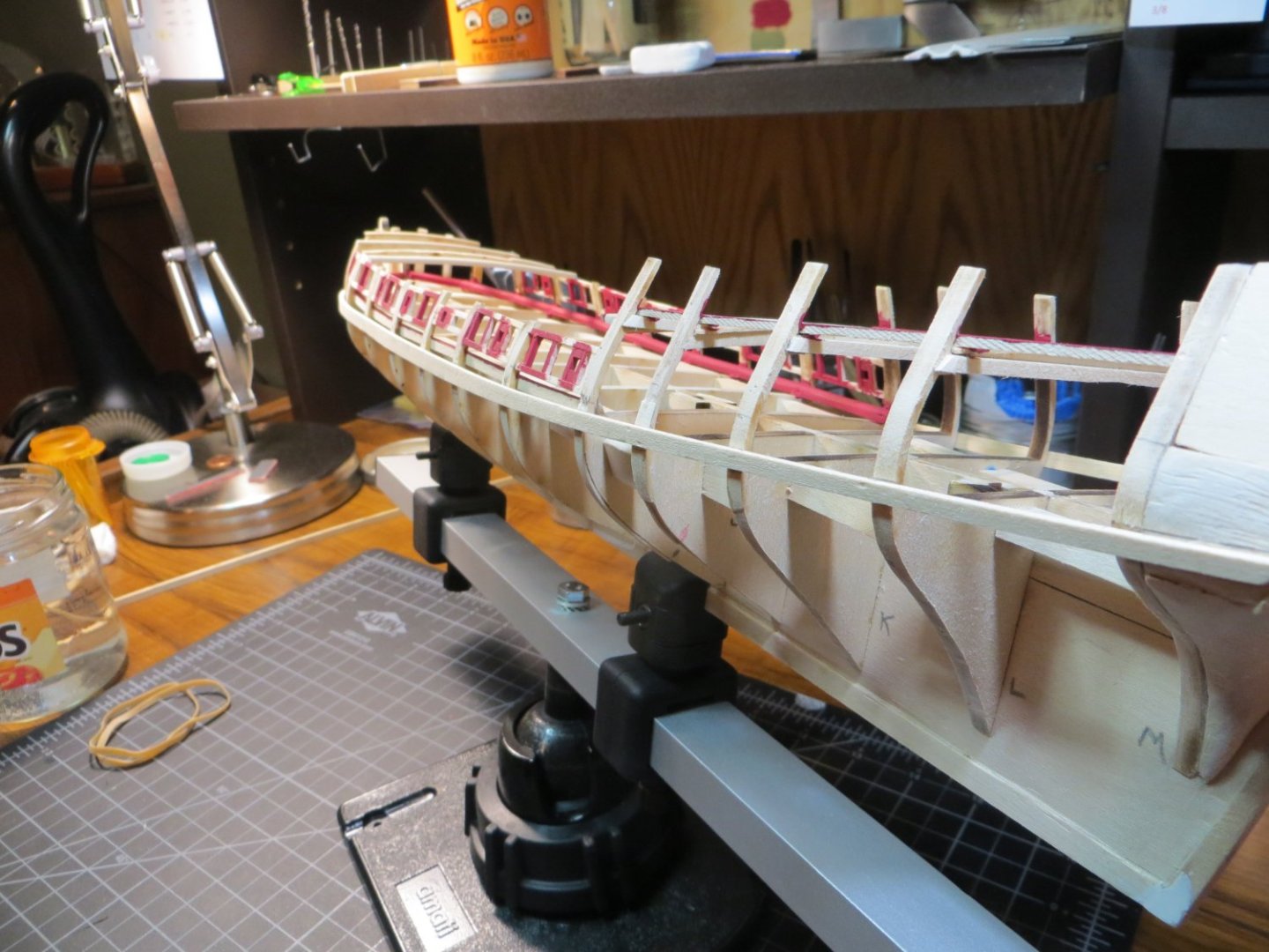
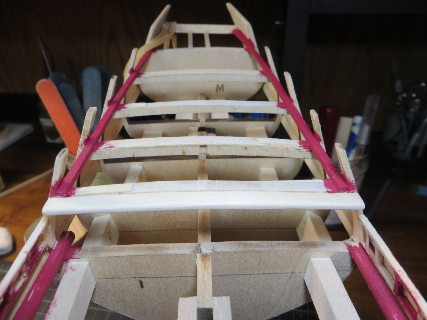
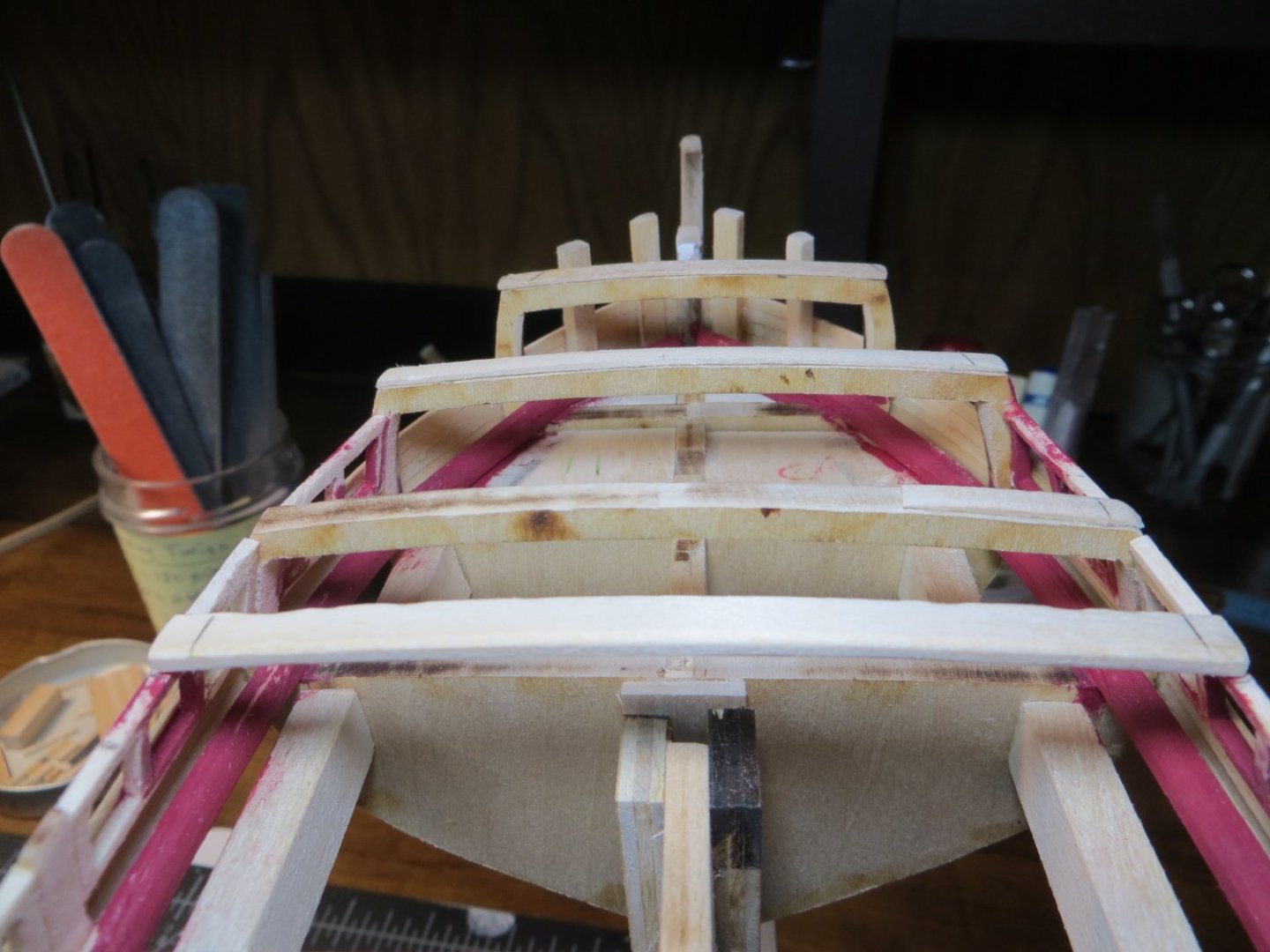
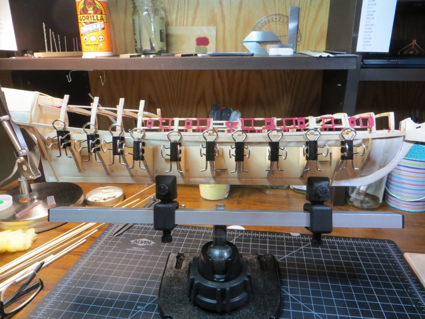
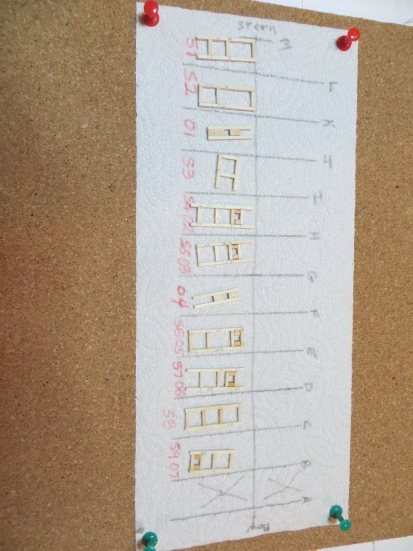
Step 22: Plank the Outboard Bulwarks above the Wale Step 23: Plank the Inboard Bulwark with “Ceiling Planks” Hello Everyone, It’s taken me some time to get to the point where I’m ready to post some progress. Doing the planking above the Wale has been a slow process. I’ve been moving slowly and spending a lot of time trying to understand the blueprint plans and how everything fits together. Taking my time and trying to do it right! The instruction manual outlines several rules for planking. For the most part I followed these rules. Before starting to plank I made a diagram showing the way I wanted to stagger the butt joints for each strake. I broke the strakes into 3 planks each. Pic of the “Planking Rules” and the bundle of 1/32” x 3/32” stripwood from the kit (WP-3603) I worked on the outboard and inboard planking simultaneously. I started on the hull side, beginning at the wale and working up to the rails. I alternated adding a full strake on the port side and then the same on the starboard. This is recommended to make sure things don’t get out of alignment. For the outboard planks at the bow, I measured the length of plank required for that position and soaked it in a glass jar for about 5 to 8 minutes. Then I used a curling iron I “borrowed” from my wife to bend the plank to fit the curve of the bow. Be sure to apply glue to the top of the entire lower plank below to hold the bottom edge of the new plank above it. Here is my process. Soaking a plank in a jar of water for bending to fit the bow Bending the front end of the plank with the curling iron Clamping the damp plank in place to dry fit it to the shape of the bow Applying glue to the top of the last plank before setting the next one in place Plank clamped while the glue sets The completed plank after glue is set and clamps removed First 3 strakes on starboard side at the quarter deck area 4 strakes completed; view at midship area. Another plank on the starboard side with glue setting After planking halfway up the outboard side, as measured at the midship gundeck area, I switched to the inboard ceiling planks. I thought this would make it easier to get my fingers inside the deck area and allow me to see what I’m doing. Before starting on the ceiling planks, I sanded down the inboard side of the bulkheads to 1/16” as called for on the plans. This was done for the gundeck and focsl. It did not appear to be required on the quarter deck. I just sanded to even them out. I alternated back and forth between inboard and outboard once I got to the gunports & oar ports. I used full length pieces of stripwood on the inside. I planked over the holes both in & outside. I cut the holes out on each side after completing each strake of planks. I used an Exacto knife equipped with a saw blade to do the cutting. When finished, the edges were cleaned up with jewelry files. Ceiling planks on the port side showing the cutout gun & oar port holes The last strake at the top of the gundeck was done in 2 sections instead of 3 I have a number of spots where my clamps pushed the plank too tightly and formed a “sunken” spot. These 1/32” boards are very pliable. I will fix these later with sanding and filler, where needed. I found it helpful to glue some extra 1/16” thick supports between the bulkheads in various spots as I approached the top of the hull. This was especially necessary for the top couple of strakes where the bulkhead extensions were like short nubs! These provided more surface area for gluing. The final (top) strake that runs the full length of the hull will get a molding strip installed over the top of it. This will be done later after sanding and installing the railings. Pic showing extra supports along the bulwarks, between the BHD extensions The next step is the quarter deck planking. The next plank is the first one that stops at the end of the q-deck. Actually, it goes a about an inch farther to form a step to the gundeck rail. Next there is a plank that gets the “Covering Board” strip installed over the top of it. Finally, there are 5 more planks to reach the top of the quarter deck. My plan here is to glue the gunport lids directly to the hull. Therefore, no holes in q-deck area. Pic showing 3 planks installed on the outboard quarter deck & ceiling planks being installed Top strake that gets the molding strip and also the step-down plank from the quarter deck I left some over-lap at the front and back of the quarter deck planks for trimming and sanding later The last step for this subject is the last couple of planks at the focsl. I added a couple of extra supports for gluing. I soaked these planks and used the curling iron for the curve at the bow. Here are some pics of the completed work. I still have to do some sanding and filling before painting anything. Pics of completed planking at the focsl, port & starboard sides Most current pics of completed planking around the ship I’m a little worried about the next step. I am going to install the laser-cut covering boards on the Focsl. Dry fitting shows that they do not fit too well! I have an idea for how to make them fit. I’ll let you know if it works!! Thanks, Ed


-
Exactly Right! I too had difficulty making sense of the blueprint plans for this area! He does not provide any view of this part of the railing showing the beam, waterway and railing in place, much less the qtr deck planks! I did cut the beam back. I will find out how I did when I get to planking the deck! That's still a ways off. Hopefully we help one another minimize the number of mistakes we need to cover up!! I'm finally ready to post my upper hull & ceiling planking. Should be posted soon Thanks John!
-
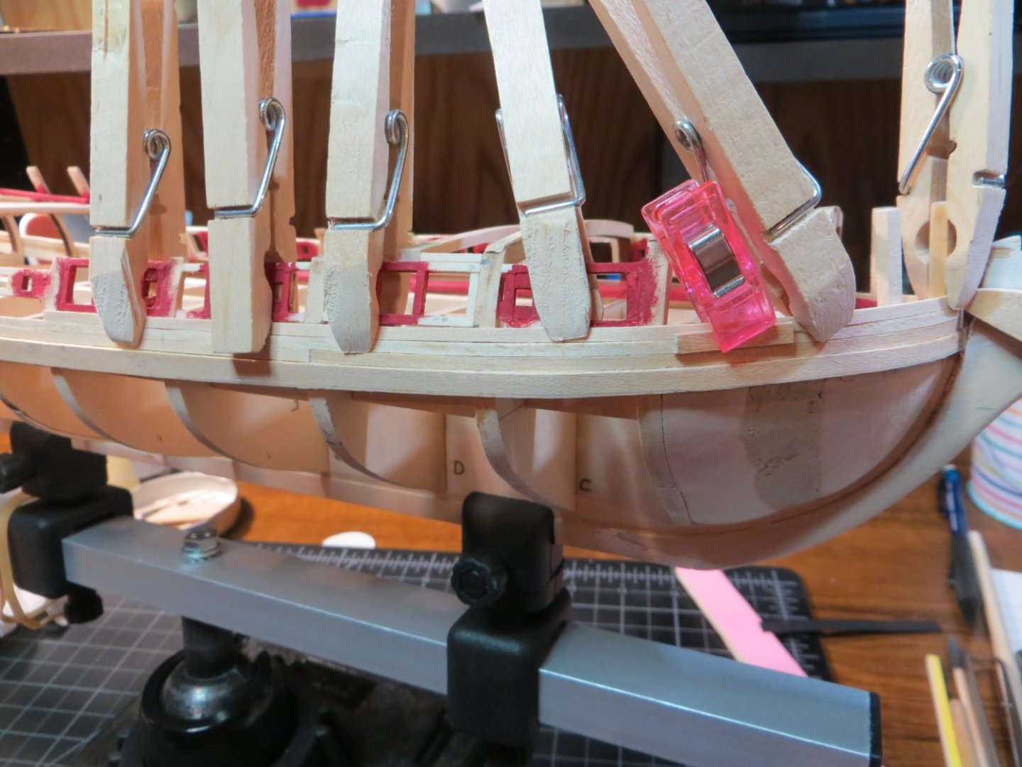
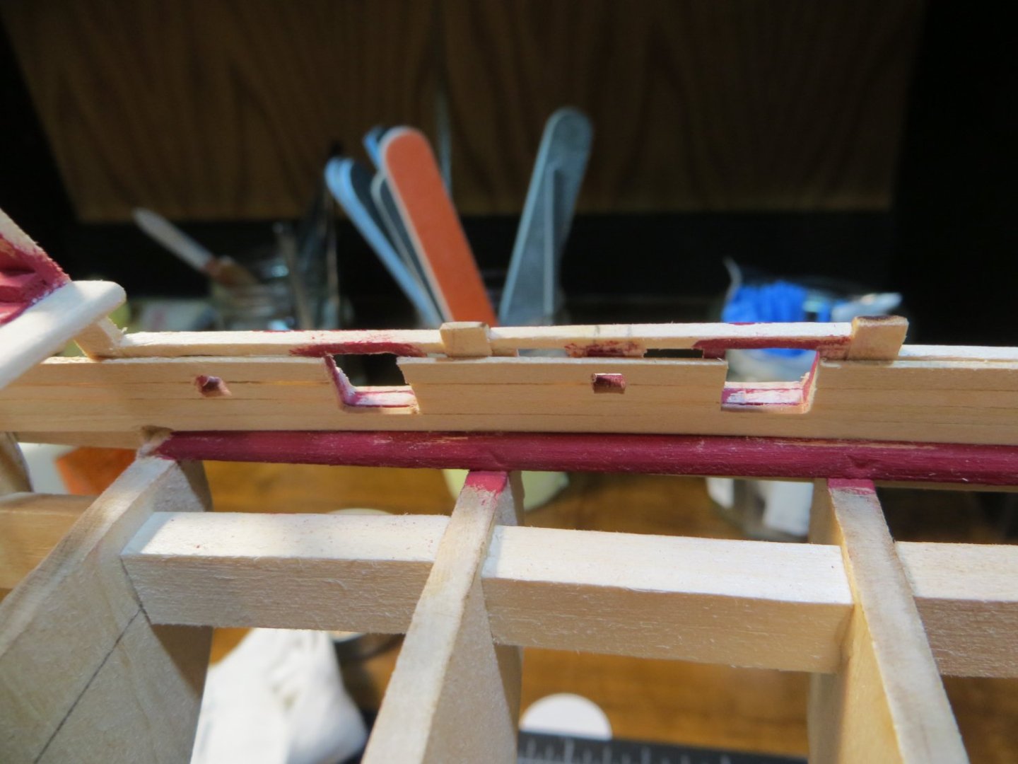
Hi John, Thanks for your answer to my question. So, your order was - plank upper bulwarks, install the railings (except on the Focs'l), then paint, then plank the lower hull. I will post my work on the upper hull planking very soon. I spent some time studying the pictures of your railings. I'm having trouble wrapping my head around the first few planks at the quarter deck. The ones just above the strake that gets the "molding strip". I think I made my beam too wide. It seems like it will be in the way of the short vertical rail that drops down from the Q-Deck to the gundeck. I have a picture of this below. I cut it to fit to the outside of the bulkhead extension. Should I cut the beam back on each side? I think I need to cut it back to where ceiling planks will sit on the red waterway. The vertical piece of railing needs to be at least as wide as the planked bulkhead, correct? Then stop the next outside plank so it's even with the forward edge of that BHD extension and continue planking the same way all the way up. I'm afraid to cut that beam! How did you get that short piece of rail to curve with the BHD extension? Thanks! Ed BTW, your Rattlesnake is looking really awesome! Looks like you will keep the upper bulwarks on the quarter deck yellow ochre. I've seen some guys paint it black and others ochre. Still deciding for mine!

-
Quick question for the Rattlesnake team. When do you recommend installing the Q-Deck and Gun Deck railings? Before or after completing the lower hull planking? I'm almost done with the upper bulwark planking both outboard & inboard. The Focs'l stanchions and railings are definitely going in after as they are much more fragile! Thanks! Ed
-
Step 19: Plank the Counter Step 20: Install the Wale Strake Step 21: Install Focsl & Qtr Deck Breast Beams In my previous post I showed the work on the Wale in conjunction with my struggles to taper these planks using the cheap block plane I purchased at a big box store. Finally got that solved with help from Jonathan (wool32) & John (javajohn). I completed a few more steps, so I want to circle back and submit a post on the process for my steps 19, 20 & 21. The Wale is made from a 1/16” x 3/16” stripwood plank (part #3622). The bulwark planks above it are 1/32” x 3/32” stripwood planks (3603). The measurements from the kit blueprint plan matched up to the side of my model to indicate that the top edge of the Wale should fall about even with the bottom edge of the Waterway. I tried to make a “tick strip” with a piece of the stiff card stock to mark on the bulkheads. (This didn’t work very well. It ended up being significantly longer than the available space on my ship!) I finally just eye-balled the position with the waterway and marked the bhd’s with a pencil. I decided to make the wale out of a single piece of stripwood to ensure that it is straight and level along this line. Here are the construction steps I used. Step 19: Plank the Counter – The first thing I did was plank the Counter block at the stern with 1/32” x 3/32” stripwood. I squared off the outer edges with a sanding stick. Planks above the wale run straight across the outside of the counter. Eventually I will sand the 2 edges into a miter-like cut. Counter Planking Step 21: Install Focsl & Qtr Deck Breast Beams While I was waiting for my new block plane, I installed the Focsl & Qtr Deck Breast Beams 1. 3/32” x 3/16” pieces of stripwood are required. The focsl beam is supposed to sit on a pair of support beams between bulkheads C & D. My gunport frames are higher than normal because of the replacement cannons, so I ended up setting the beam right on top of the frames. 2. Sand the open edge of each beam to make a rounded edge 3. The beam needs to be bent to match the curve of the focsl deck camber. I remember reading in other logs that you should keep the laser cutouts from the bhd’s. I’m glad I did! I soaked the beams; rubber banded them to the top of their respective cutouts (C & I) and let them dry out overnight to the correct camber. 4. Glued them in position the next day Focsl Deck Breast Beam behind Bulkhead C Quarter Deck Breast Beam in front of Bulkhead I Step 20: Install the Wale Strake 1. Once I received my new block plane, I tapered both wale planks (see pics in above post #69) 2. Dry fit the wales on the ship. Word of caution on two points: a. I assumed that the full width of the wale plank would match the plans around bhd’s G & H. The plank on the plan is 1/32” narrower than 3/16” full size of the actual kit wood. Either a different size of wood was used back then or they tapered the entire plank. I saw no reason not to use the full width and adjusted the tapers at the bow & stern to be a consistent percentage of the difference. b. I made a bend in the bow end of the wale so that it followed the upward curve of the waterway. After I installed the wales on both sides, I did not like the way this was looking. So, I unglued this area and dropped it down to make a gentler curve. I hope this wasn’t a mistake, but it seemed that’s what the wood was telling me to do! A little less edge bending. 3. Steps for Installing the Wale a. These planks are quite a bit heavier than the planks I used on Bluenose (which were the same as the Snake’s deck planks). I needed to soak them longer (about 15 minutes) to get them pliable enough to bend to the curve at the bow. I use a 2-foot-long PVC pipe that is capped at the bottom for soaking a full-length plank. b. I took Dave_E’s advice and “borrowed” a thick diameter curling iron from my wife to make the curve. Dave, it worked great!! Clamped them in position until they dried to the proper shape. c. Remove the clamps; apply PVA (I use Gorilla Glue); re-clamp in position until dry Wale installed on the port side of the ship 4. Glue in the Timberheads and Knightheads – I made the cutouts in the filler block and the timber pieces earlier. To glue or not to glue them now, that was a question. I test fit the laser-cut covering board. It looks like I will need to edge bend the aft ends of the covering boards into the ship to make them fit on the focsl deck beams correctly. I decided I needed to glue the timberheads & knightheads in position now. I used the covering boards to align them underneath. I am going to wait until I’m done with the upper hull planking before finally gluing in the covering boards. This will make it easier to adjust the 1/32” overhang. I already started planking the bulwark above the wale. I will save that for my next post.
-
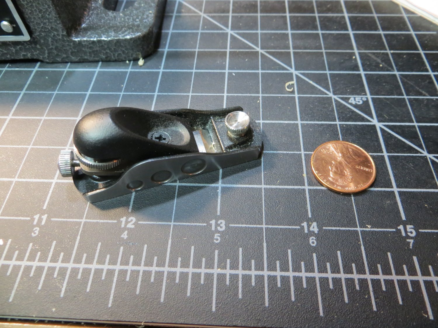
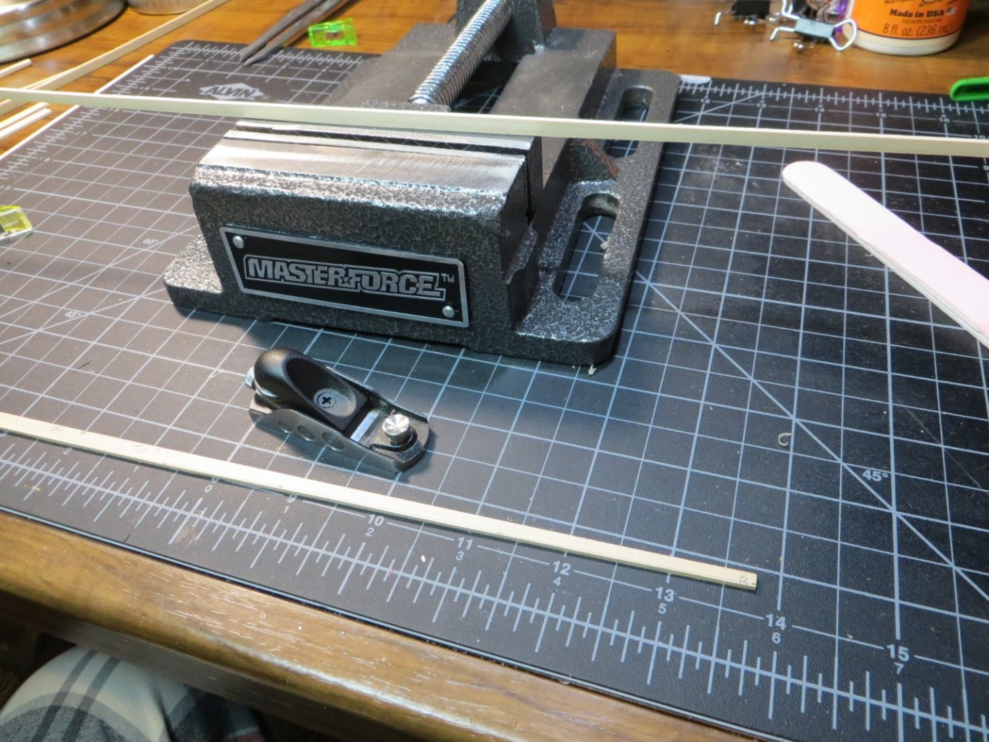
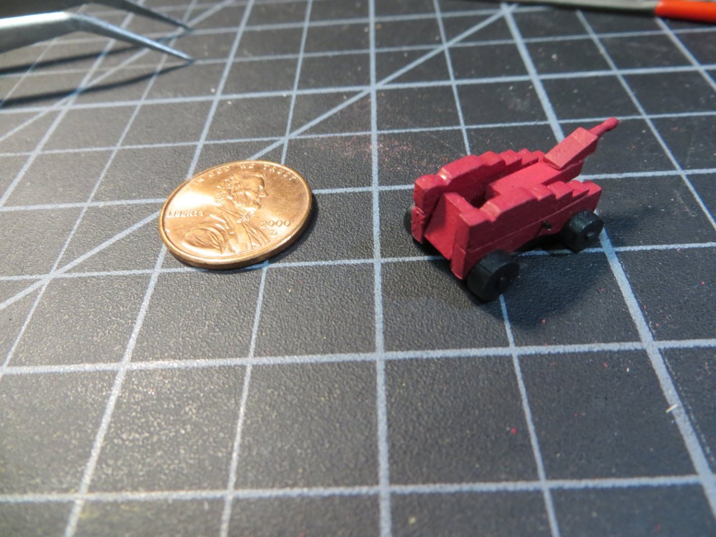
Hey John and Jonathan, I wanted to let you know that I received my Veritas miniature block plane from Lee Valley late yesterday. Spent some time working today to get the Wale strake installed on the starboard side. The Veritas plane was amazing! I cut two planks to length and clamped them together in my hobby vise. That little plane cut through the two boards together like a sharp knife through butter! I was surprised how small it was. But it is perfect for tapering planks. Here are a couple of pictures to let you see how I did. I'm going to make a full posting of this entire step once I'm finished with it. Thanks for the recommendation. I'm looking forward to planking now!!! Ed Here's my newest tool in the arsenal. You can see how small it is compared to a penny! Small but mighty! No problem tapering these 2 Wale planks simultaneously Glue is drying on the starboard wale strake. Yes, I did install one continuous plank to help align everything else above and below it more easily. Tomorrow the port side goes in.

-
Hi Bill, go real slow with the sanding. You can always take more off later, but it's a real problem if you overdo it and need to put it back on! Be careful using the Dremel. It's a great tool, but will chew off a lot of wood in a hurry if you are not careful. Everyone tries to do their best to make the model to match the plans, but you have to be quite expert to do this 100%. You may have to make minor (hopefully) adjustments to work on your version of the ship as you move along. Also, all of us have broken pieces. Wood glue and reinforcing with scrap wood is the solution when making repairs. Look ahead at what others post to make sure you are planning appropriately for a future step, as you are working on something in the present. There can be bad ripple affects if you don't. Also, listen to Old Salt (Jim). He gives good advice! Regards, Ed
-
Hi Jonathan, thanks for the recommendation. I was just checking out this plane. It looks like it is much better to fine tune than the one I have now, with 1 thumbscrew! I think I will make the investment! John, I don't think I have the patience to make this thing work! I should have purchased a better tool from the start. I like the sound of "works flawlessly".
-
Thanks Guys for all the positive feedback! It is much appreciated. Jim, I will start studying that cabin bulkhead. Is there something specific I need to be aware of? Do any of you use a block plane for tapering your planks? I used the Exacto knife and a straight edge with my last ship. That was very tedious. But I did not have to do much tapering for Bluenose. I bought a little 3" Buck Bros block plane at Home Depot and tried some practice cuts with it. I'm not getting acceptable results! I sharpened it on my stone and have the blade edge sticking out as little as possible. But, no matter which direction I plane it just chatters and chews the wood. Occaisionally I get a decent shaving. Either the equipment I'm using is too cheap or the operator is doing it wrong! I know you have to plane with the grain, but it doesn't seem to matter which direction I push. Would appreciate any tips or techniques you guys use. I looked at that video of the guy for Modelers Central. It looks easy as pie when he does it!! Thanks, Ed
-
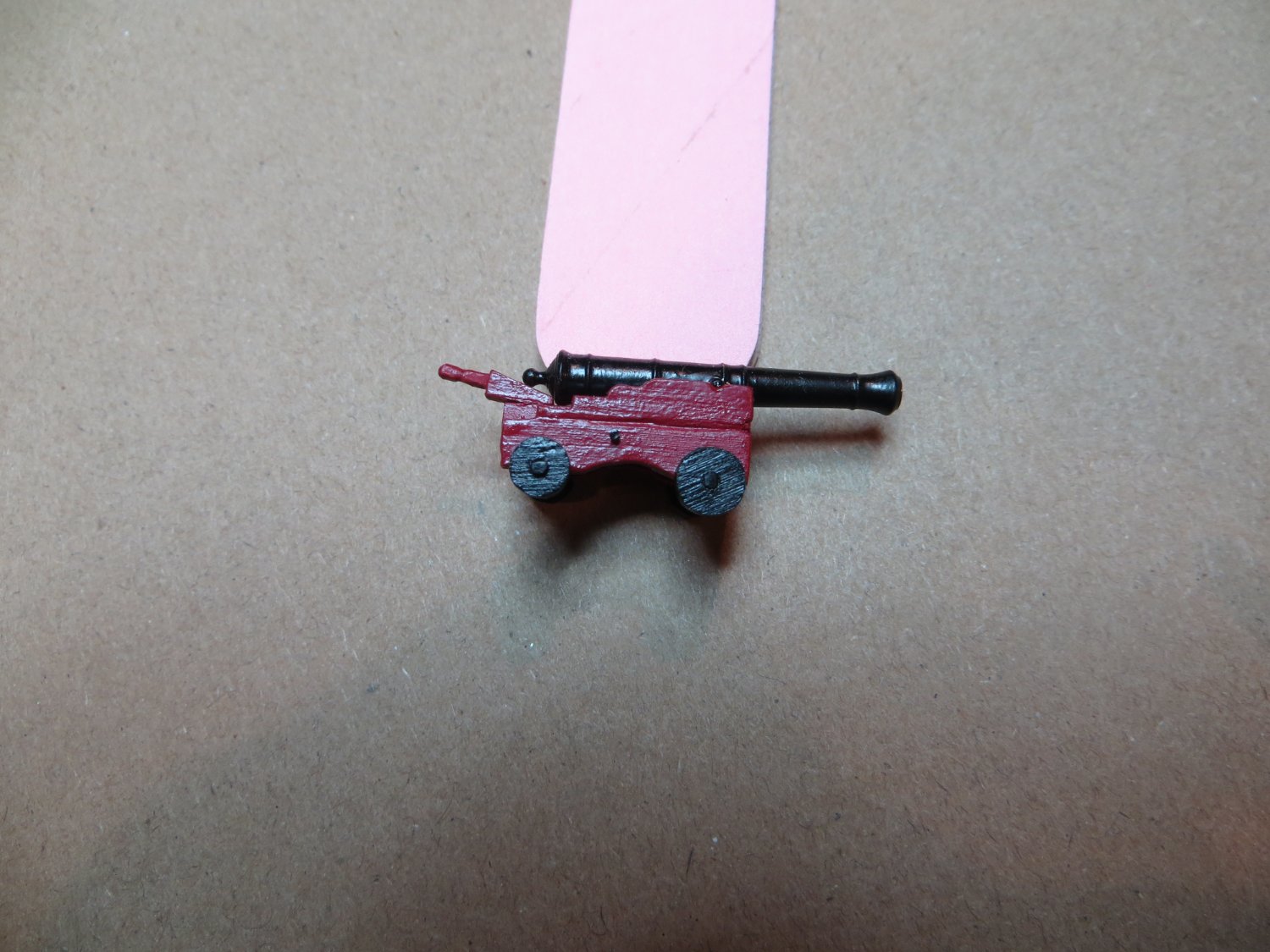
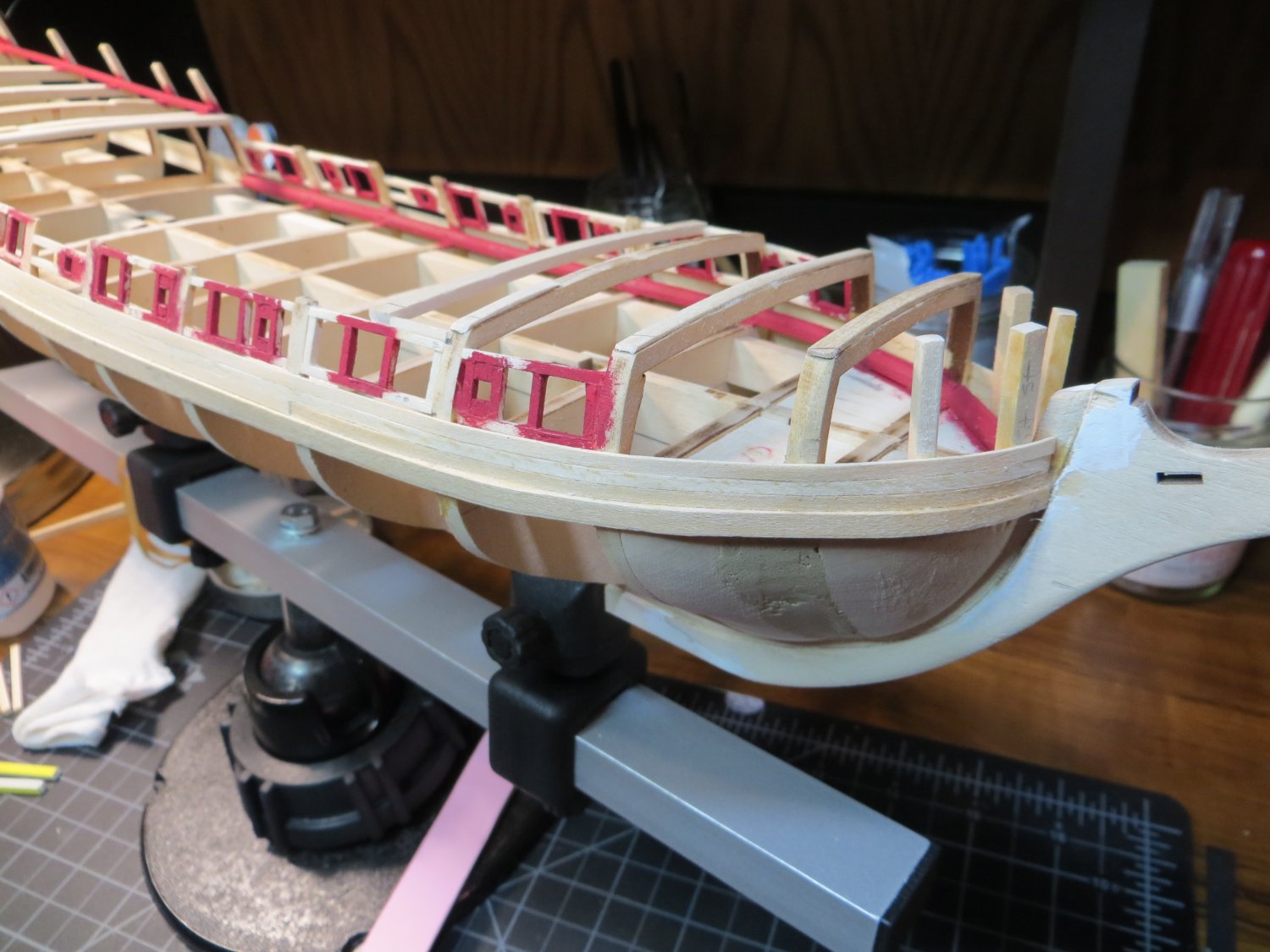
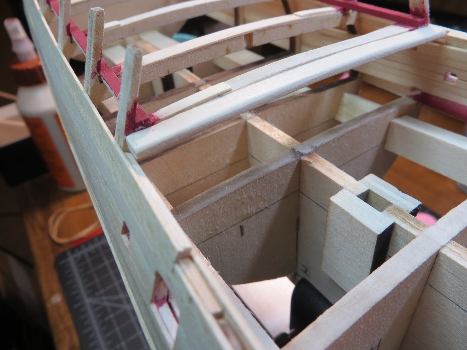
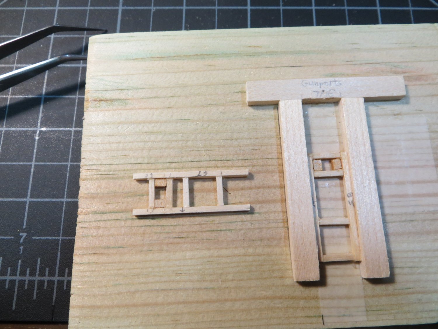
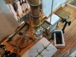
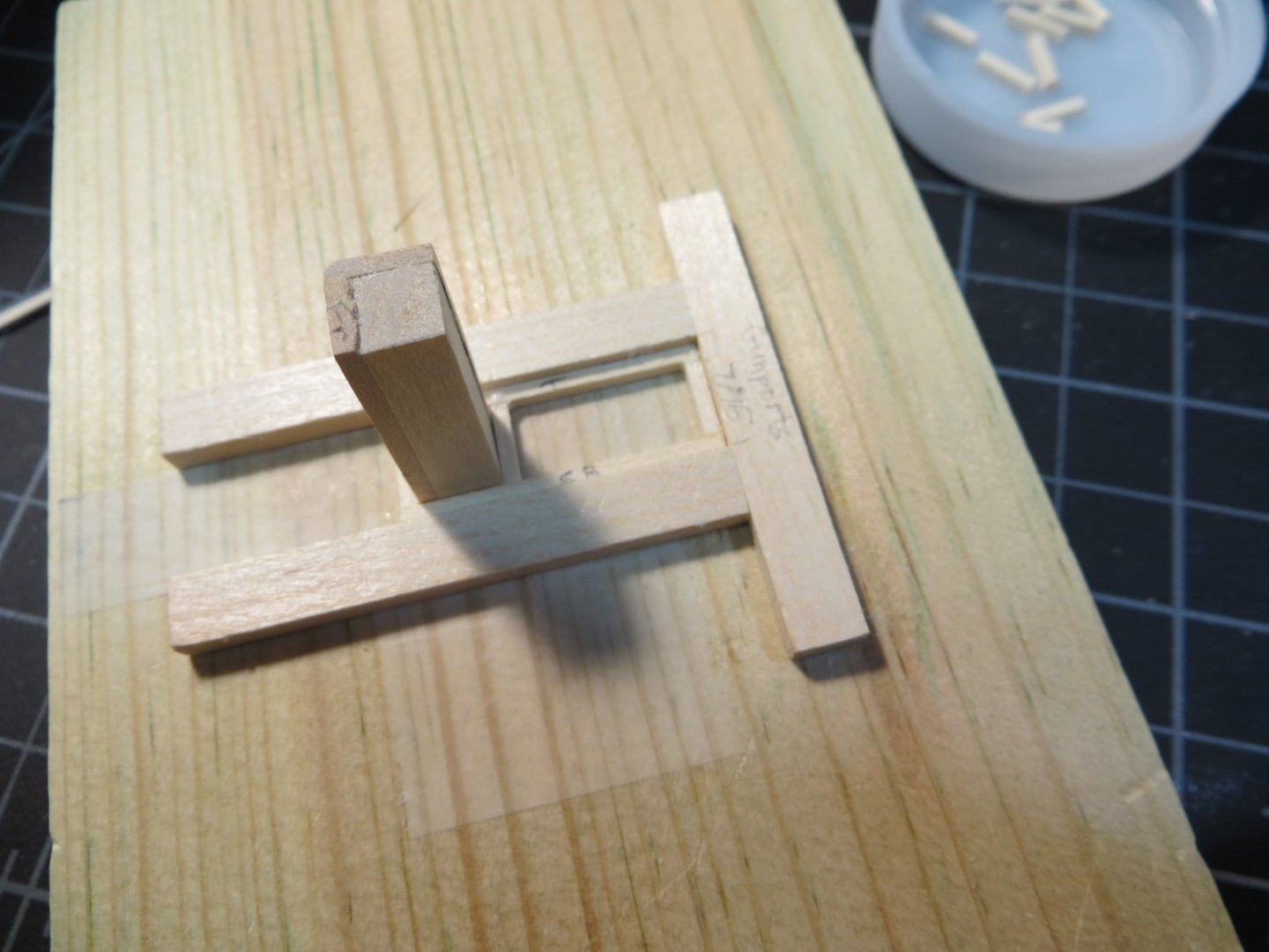
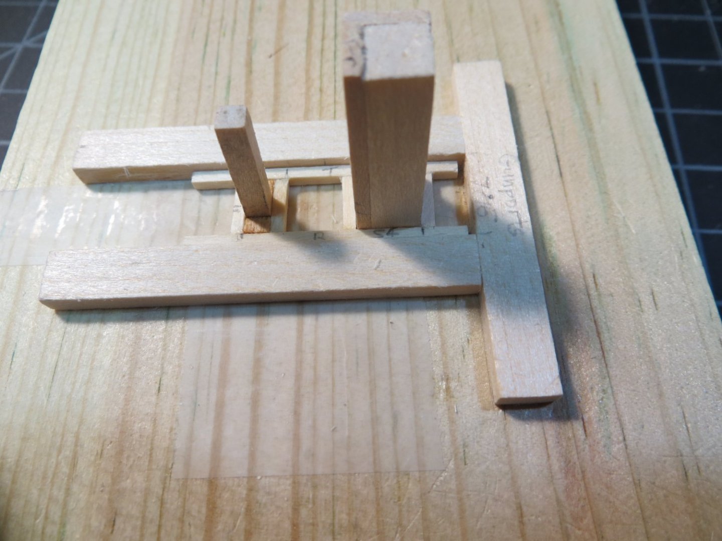
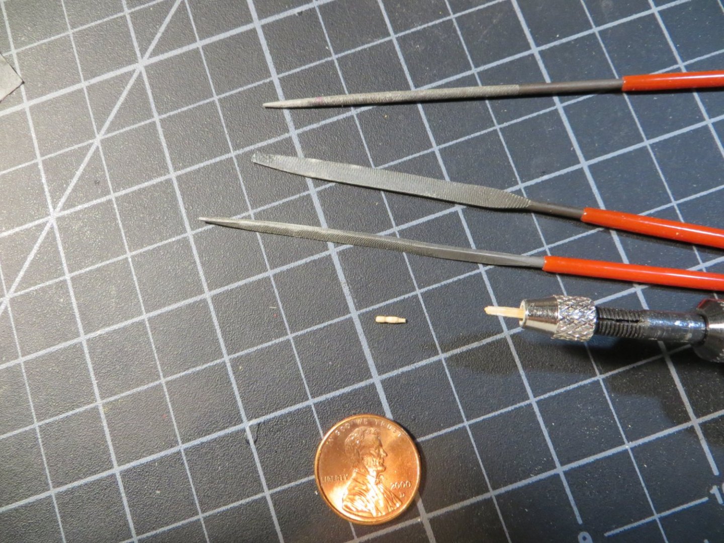
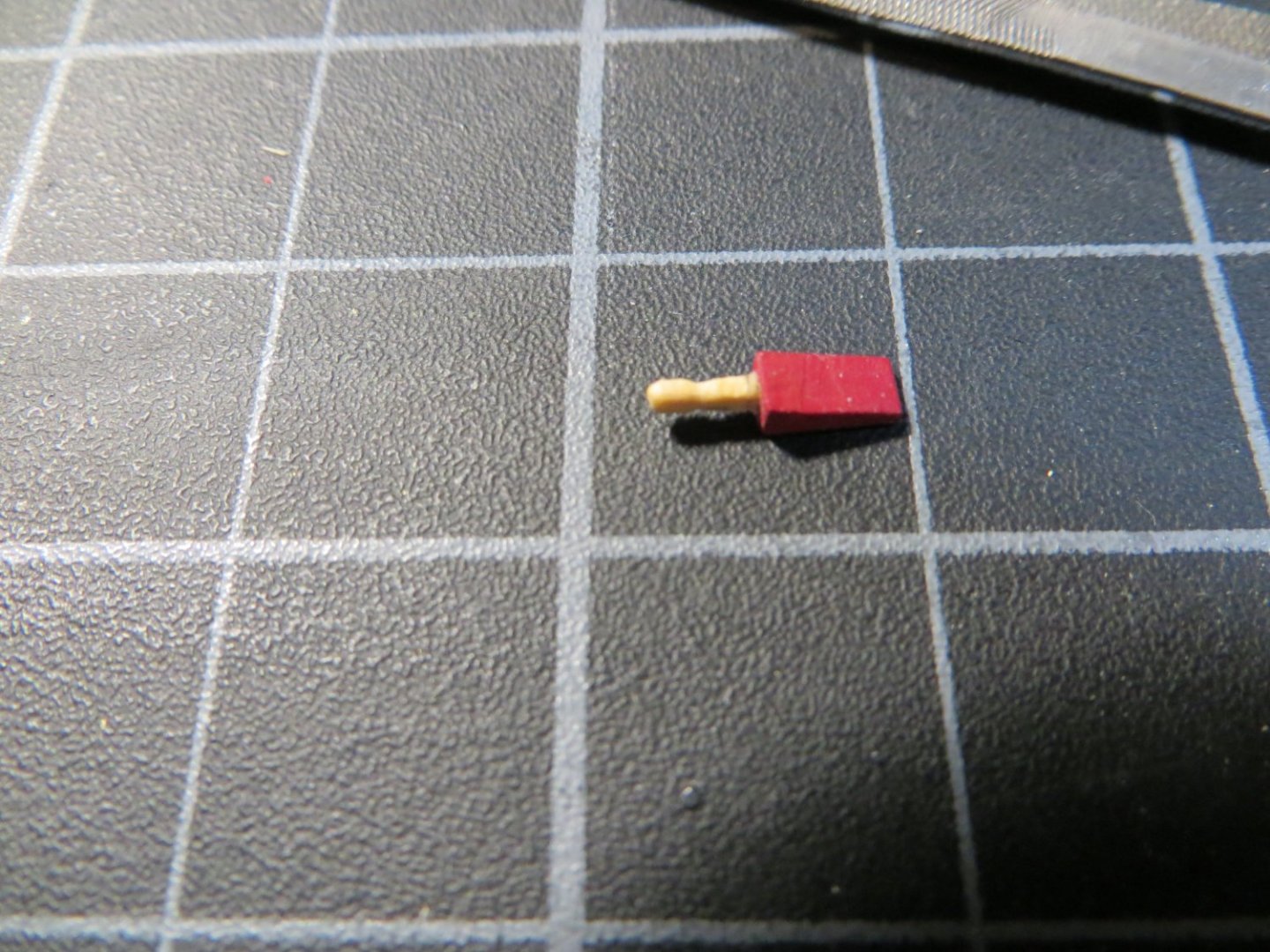
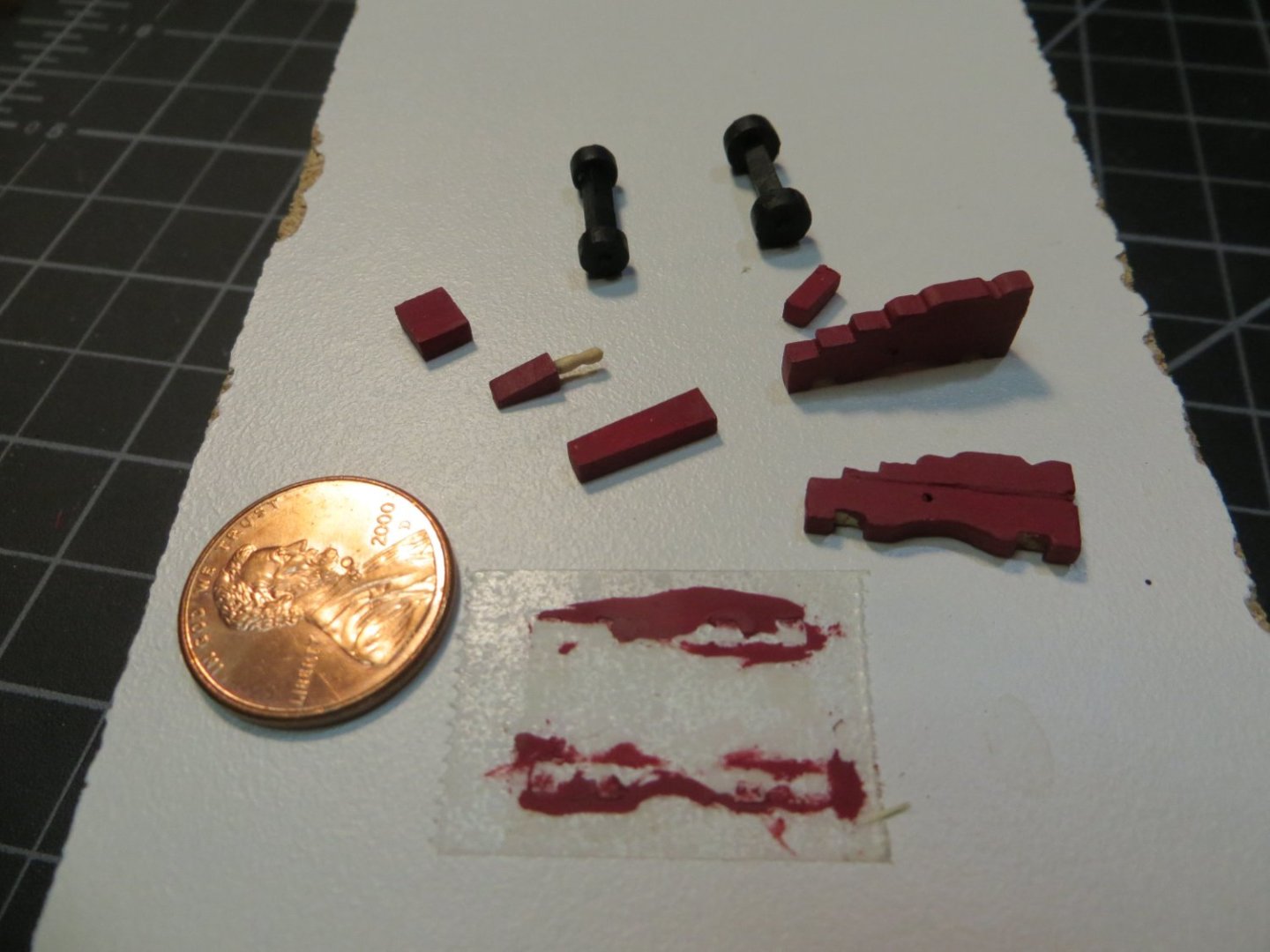
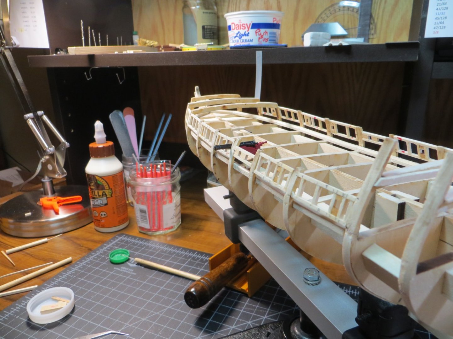
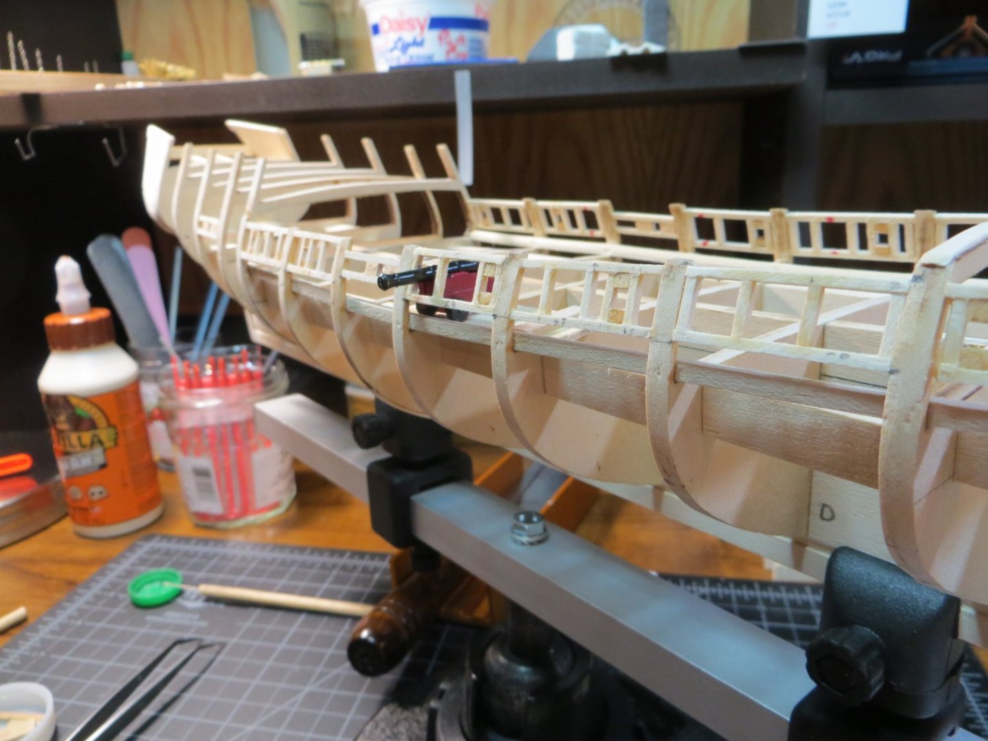
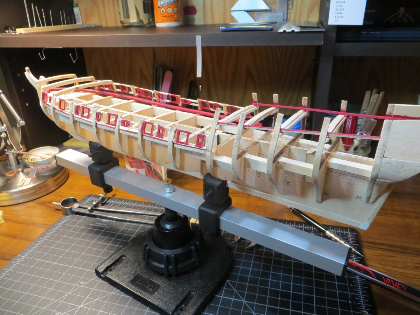
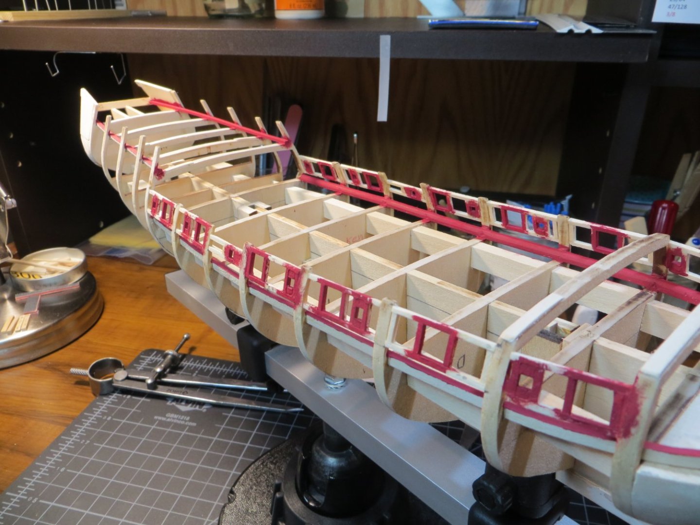
Step 17: Install Gunport Framing & Oar Sweep Holes The next step in my build process is to install the gunport frames. As with most things on this model, I did a lot of studying before I started this step. Here are some notes I made. Maybe they will be of value to someone else who is building a Rattlesnake! NOTE-1: Use 1/16” square strip wood for the gunport & oar sweep portholes. Make it flush with the outboard edge. After planking the outer gunwales, the inboard BHD wood needs to be reduced in thickness down to 1/16” to be flush with the frames. On the outboard side they must be “faired” to match the vertical curve of the hull. NOTE-2: Per Chuck Passaro, the sides of the portholes should be parallel to the BHD's and the top and bottom should be parallel to the deck! I found this to be very difficult to achieve! Per Russ, gunports must follow the deck line, at a consistent height above the deck in order for the cannons to fit properly. (I did do these 2 things.) The gunports follow the sheer (longitudinal curve) of the deck, which is not the same as the sheer of the hull! NOTE-3: Per JSGerson, even gunports that have closed lids need a frame constructed around the opening. Post #29. I gave up trying to get the frames to fit between the Quarter Deck BHD’s. The vertical curve and deck sheer combined required too much twisting and my little 1/16” square frames fell apart. I do not plan on putting cannons here. I will figure out how to make the lids fit properly after the wale planking is done. Maybe make a lip inside the lid to fit in the hole? Or can I just glue them to the hull without cutting out the hole? I will see what looks best. I plan to build my own gunport lids when the time comes! 1. Preparation work a. Make a Jig – I used Scott Larkins’ Post #45 to make a jig for a consistent size to the frames. Based the jig on measurements taken from the plans. I put some scotch tape down in the space between the jig sides to prevent glue from sticking to the jig. This jig worked great, but restricted the ability to make the sides parallel to the BHD’s because they were perfect squares. I focused on getting the bottom edge to flow with the top of the waterway. b. Build 1 cannon -- used as a test to center the barrel through each gunport frame. I ordered replacement cannons and carriages from Syren Ship Model Co. These are slightly taller than the ones in the kit and pushed the top of the frame a little closer to the main rail. Hope this isn’t a future problem! I spent 10 hours just building that first little cannon! Still need to add rings and rigging later on down the road. c. Make a small section of deck planking to stand the cannon on top of the BHD’s The Gunport Frame making jig Assembling the Syren cannon. BTW, these are really beautifully made. I learned a few things that will help me make the rest of them even better when the time comes. Shaped this tiny "Quoin" handle with Dremel and files 2. Make the frames – I measured the distance between the bulkheads with my caliper. Cut the top & bottom frame pieces to match this width. Insert into the jig. Cut the vertical sides using the jig post to get the right length (see step 3 below). Measure the distance from the right side of the frame to the BHD & mark this distance on the top frame. Use the jig post to position the two vertical frames and apply PVA glue. Be sure to remove the post before the glue sets!! I added vertical posts at the ends for strength and to provide more surface for gluing to the BHD. 3. Cut a pile of vertical posts – these are all the same size, so may as well make a bunch at one time. I taped down a wood strip in my razor saw miter box to match the length needed. Actually, made slightly larger and sanded them to fit. 4. Set-up the Oar port – Take measurements from the plan. Used a 1/8” square piece of stripwood as a jig to make the oar port. Cut scrap wood and glue in place the correct distance from the cannon gunport. Put a small piece of scrap wood above and below the hole. 5. Glue the frames to the BHD’s – Adjust the frames to the sheer of the deck. Do this by lightly sanding the ends so the frame can fit btw bhd’s to match the sheer of the waterway. This was only marginally successful. Use PVA glue once all are fitted. I started on the starboard side and made all the frames first, then glued them in place. By the time I got to the port side, I built them in the jig & immediately glued them as I went down the hull. Making the frames in the jig Starboard side ready to install on the ship Pictures of the completed frames Step 18: Paint frames & waterways red I first installed the “cover boards” on the quarter deck. This took a bit longer than expected. I ended up having to add a few more shims on top of the quarter deck to smooth out some dips along the edges. Then hand brushed using the red hull paint leftover from Bluenose. I looked at some other red colors, but liked this one the best. As I was installing the last frame on the port side, I discovered that the waterway was noticeably higher at the quarter deck (bulkhead I). The port side of the bhd is higher than the starboard, which raised the waterway up. I loosened the glue & cut off the waterway on an angle. Then sanded the wood down until the 2 sides were even. This area will be hidden behind the cabin wall, so it should not be noticeable. Current views of the Rattlesnake Sorry, for the long-winded post. There was a lot going on with these couple of steps! Next step is the wale and bulwark planking. I have a few questions about that, but will use a separate post. Thanks, Ed


-
Dave, Welcome back home! Part of the fun of going on vacation is remembering there's no place like home! I think your stern piece looks great. I kept touching up the brass, then having to touch up the gold I got on the blue and vice versa, then repeat...! I finally said to myself, this has to be good enough. Happy New Year! Ed
-
Welcome to the Rattlesnake club Bill. I second and third everything mentioned by the others. I'm certainly not an expert by any means. This is my second POB build. But I really try to detail my build process. I was a corporate trainer in a previous life!! I try to share my mistakes (what not to do) as well as what you ought to do and how I did it. The modelers on this site, especially these Ratt builders, are a great source for information. There are a lot of quirky things with this MS kit and we've all worked our way through each of them, like shimming the keel. Start your own build log, take lots of pics and ask your questions to get feedback. Good luck! Ed
-
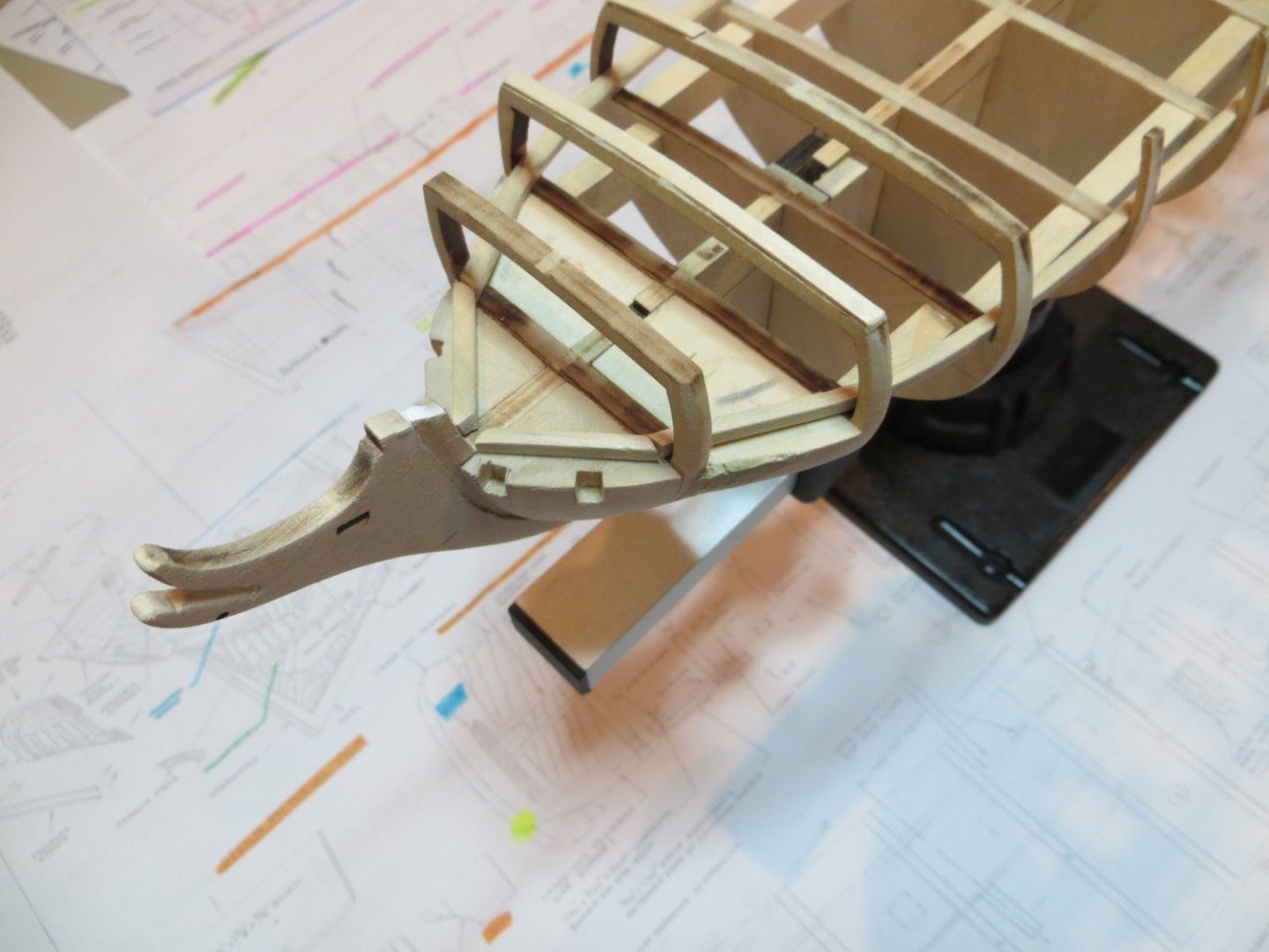
Jim, I'm actually planning to just leave it the way it is. I figure the end of the bow will be hidden under the forecastle deck. I was thinking ahead to when I will need to bend the hull planks around that sharp turn at the transom. Might need to use Dave's technique for applying heat to the wet wood.
-
Dave, what do you use to heat it? I used hot water to start with. But it had cooled off by the time I used the wood.
-
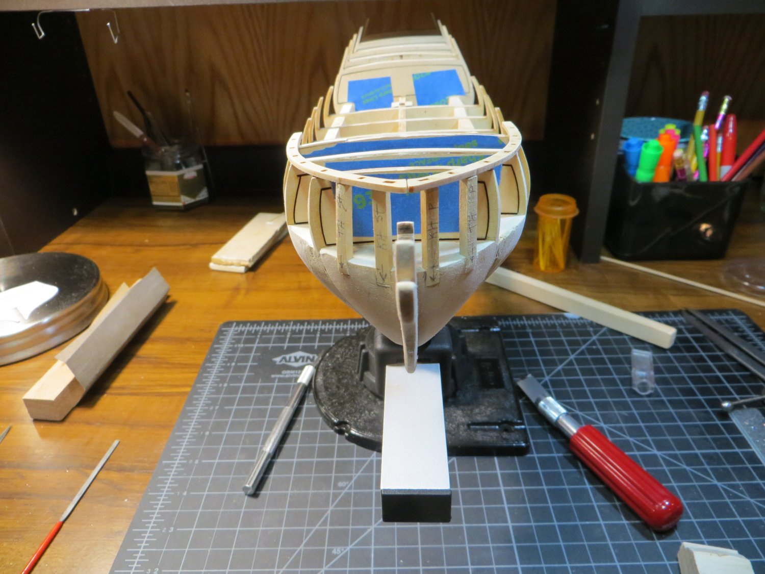
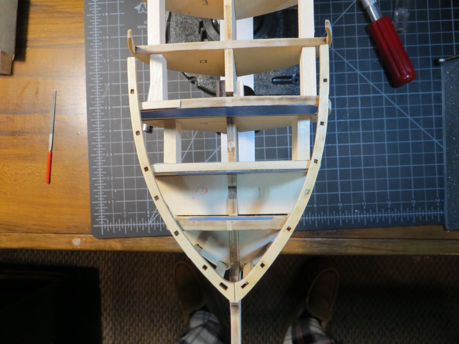
Oops! Sorry about that! Yes, I meant to say gun ports. Dave_E, this is for your information. Here's how I handled the waterways, as Jim is talking about. I'm assuming that the deck area will not be visible past the cabin bulkhead wall or at the bow, forward of BHD "A". Here are a few pictures of what I recently completed. Here is the waterway after soaking for a couple of hours in water to soften it up. I clipped it in place overnight and then glued it the next morning. After gluing in place That 1/8" square strip wood was impossible to bend at the point of the bow! I soaked it for 2 hours and could not get that end to budge without possibly breaking. So, I cut it off at A and glued it at the bow so there is someplace to butt deck planks up against. IF I need to plank that far forward. At the cabin wall, I ran the waterway just past BHD "I". I will decide if it looks better to build the cabin wall around the waterway or cut it off flush there. This way I have the option. But, I will not be taking it all the way back through the cabin. Started working on the gun port and oar port frames. I built a jig that I hope helps with this process. I'll let you know how it goes. I still need to build 1 cannon and some temporary deck planking to test the positioning of the portholes. Thanks, Ed

-
Thanks Jim! I just put in the waterways yesterday. Per your advice, next up will be the waterways then!
-
Thanks a lot guys! Means a lot coming from all of you. I'm just trying to hold my own in this company of outstanding shipwrights! Hey, I've got some questions or perhaps confirmation about which stripwood to use for planking in various locations. I've tried measuring the width off the blueprint plans, but these do not match any of the wood supplied in the kit. When I look at pictures of Rattlesnakes on this forum some of the planks look wider. Based on the large number of wood strips provided for 3 of the bundles (48, 50 & 50) I'm thinking as follows: 1.) Bulwarks - inboard ceiling & outboard above the wale use WP3603 1/32 x 3/32" 2.) Lower Hull - use WP3622 1/16 x 3/16" 3.) Deck Planks - use WP3620 1/16 x 1/8" Has anyone figured this out? I think I'm going to lay the Wale strake early before installing the gunport frames to provide a visual position for the sheer of the deck. Appreciate any feedback others might have. Thanks! Ed
-
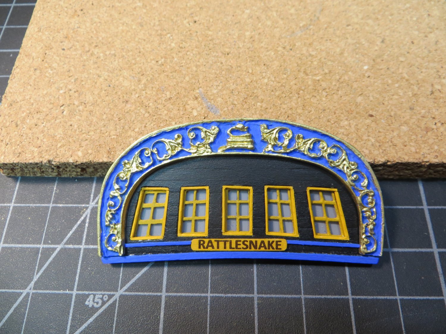
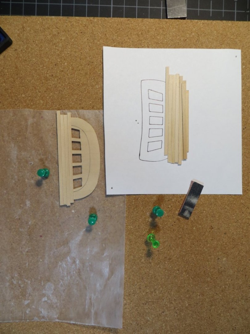
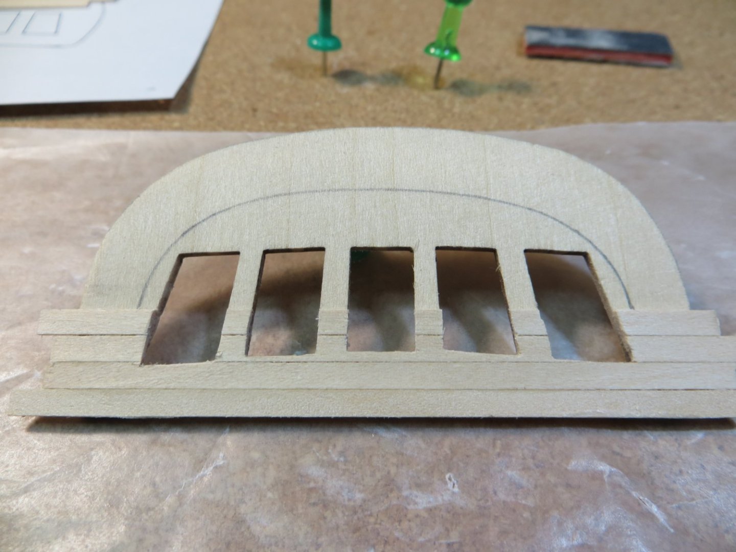
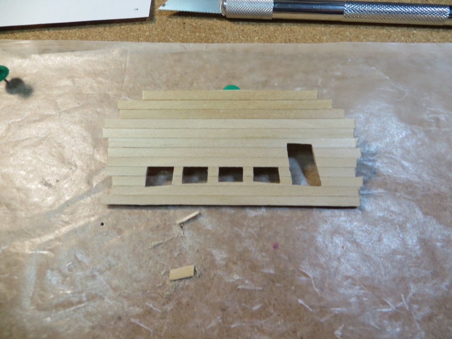
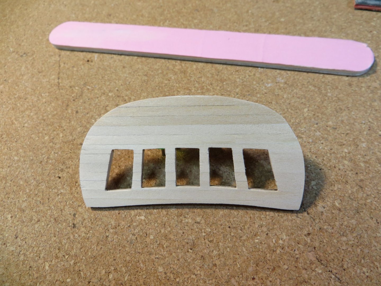
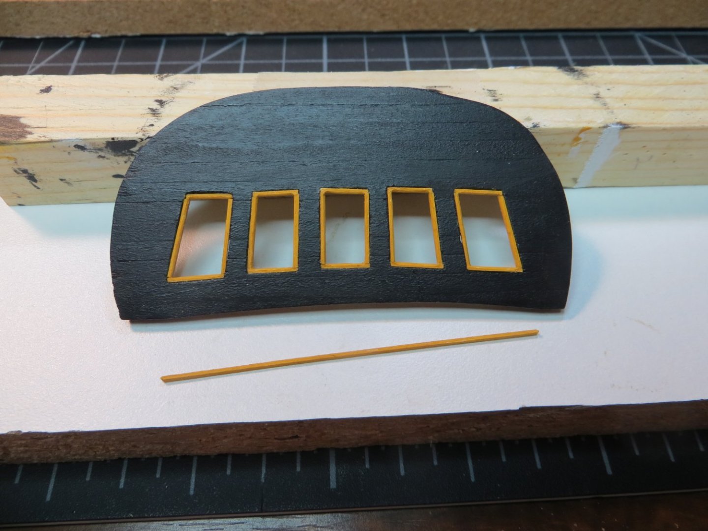
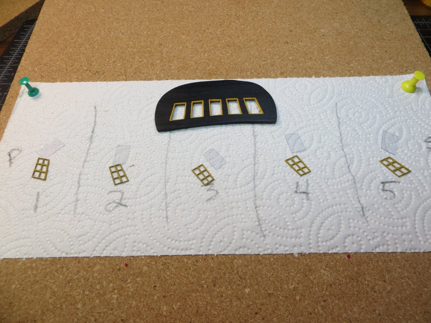
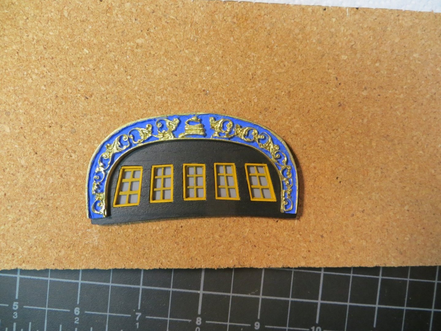
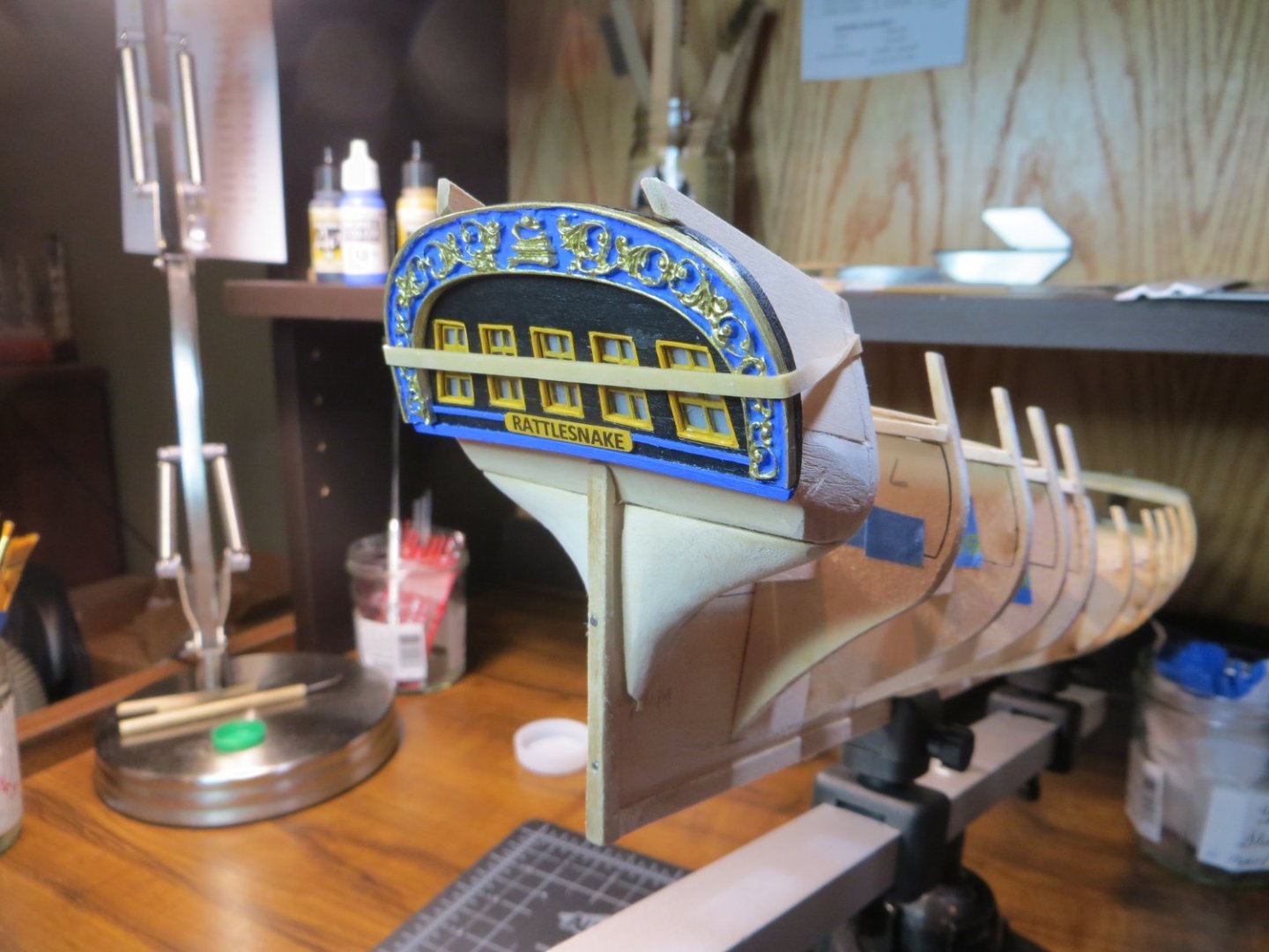
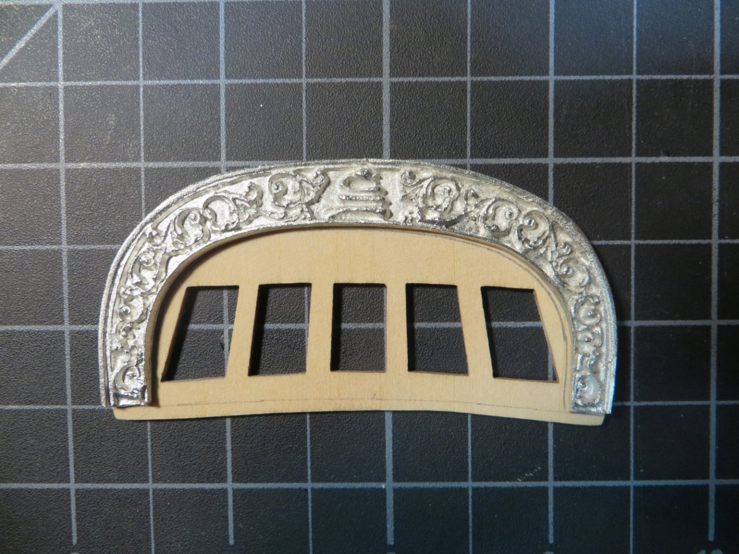
Step 14: Prepare the Transom Step 15: Prepare the Transom Carving I completed a couple of more steps in my build process with the transom & transom carving. I worked on these simultaneously. First, I sanded the back of the transom to make it thinner before planking with 1/32 x 1/8” stripwood. I got it down to between 9/128 – 5/64”. I didn’t attempt to pre-bend it to wrap around the end of the Counter block. After adding the planks, windows and trim it would no longer bend!! But I used 6 rubber bands to hold it around a large pitcher! After ~24 hours it made a slight bend. The transom seems to be a place where modelers use their creativity. Mine is a blend of multiple ideas I liked from various builders, as well as my own. I used this color scheme: Black Transom; Yellow Ochre for window frames and a nameplate plaque that I made. Carving background & Trim wood is Ultramarine Blue. The scrollwork on the carving is Modelmakers Brass enamel. I use Vallejo acrylic paints everywhere else. After planking the transom, I painted it black. The Transom window frames were removed from Thickset F and the char sanded off. A quick test fit found them to be way too small! So, I cut some 1/32” square stripwood to insert as trim at the front of the window openings. I painted the trim with Yellow Ochre before gluing in place. I also painted the window frames. Cut pieces of plastic packaging to size to fit in the back of the window openings like glass. Used a touch of CA glue to sandwich the undersized window frames between the trim and the “glass”. Painted the back of the windows a Light Gray that I had left over from Bluenose. I decided it was simpler and pleasing, at least to my eye, to make all the windows instead of the dummy in the middle. Meanwhile, I was working on the transom carving. I did a lot of prep work before painting. I washed it in an ultrasonic jewelry bath (I actually do this with all the brittania metal). Then I polished it with the Dremel. I still did not like the overruns of metal all over the piece. So, I used a small carving burr in the Dremel and drilled out most of the excess metal. I think this turned out pretty well. I had planned to do a 2-step with acrylic paint over enamel and a rubbing alcohol wash to expose the scrollwork. I read about others doing it this way. I painted the entire piece with brass enamel. But then I decided to simply paint the blue background with a super fine brush under my magnifying glass/light. This worked quite well. I was able to wipe off any blue that got on the scrollwork with a damp dental swab! For the ship’s name, I really liked the way builder Dziadeczek used a sign board. I cut a 1/8” x 3/32” x 1.5” plank & painted it yellow ochre. I used clear laserjet decal paper w/ black lettering for the ship name. I applied 3 coats of Micro-Sol to help dissolve some of the decal material. I needed to do something with the empty gap below the transom carving. So, I painted a single wider molding strip at the bottom of the transom. Painted it Ultramarine Blue. The name plank was glued between this molding and the windows. This molding covers the space below the carving. Finally, inserted a pair of 1/32” molding strips between the name plank and the transom carving on either side. Used a rubber band to hold the finished piece in place to see what it looks like. I also installed the transom beam across the transom supports. I'm not sure when I’m going to actually attach the transom to the stern. Probably just before planking the bulwarks or when it becomes necessary to continue with the upper hull. Next step is to install the waterway.

-
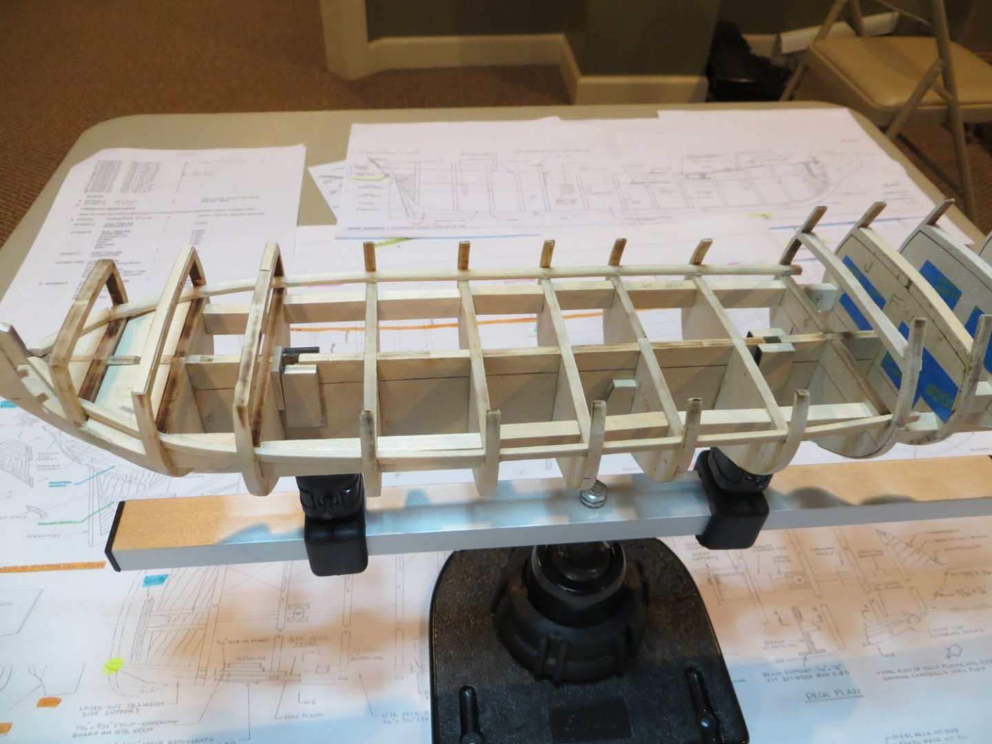
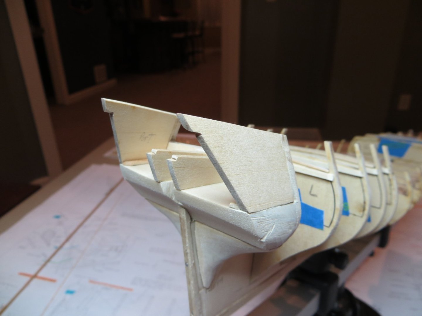
Stage B: Upper Hull – Planking & Deck Details Step 12: Knightheads & Timberheads I completed a couple of more steps with my Rattlesnake build by installing the Knightheads & Timberheads. From the plans it looks like these are about the size of a hull plank. I see that some builders use heavier pieces of stripwood to provide more support for the hull planks as they curve around the bow. I decided to follow this plan, but I don’t want to go too crazy. I kind of stumbled onto using the center posts leftover on the thick set for the bulkheads. Standing sideways the 3/32” depth is good with the lasercut Foc’sl railings. I cut 4 of these off and installed them. I used the Dremel with a cutting burr to draw the cut down the filler block at the right depth. Finished with files & sanding sticks to square up the hole. I’m going to wait until I’m ready to install the railing before gluing the pieces in place. I foresee some adjustments being required to line everything up. NOTE: I did not consider the fact that a cannon gunport needs to fit between bulkhead A and the knightheads. Fortunately, I unwittingly left enough room for this! I did use the blueprint plan and some dividers to space them out. I may leave these two gunports closed anyway. Step 13: Install Inboard & Outboard Transom Supports Next up is the Inboard & Outboard transom supports. These are provided as lasercut parts. My inboard supports were too short to reach the end of the counter block. I saw in someone’s Rattlesnake log they had the same issue and used a piece of scrap wood to extend the supports so they would fit. I'm not too shy to "borrow" a good idea! Everything got glued in place with Weldbond. I was afraid that the Outboard Supports just hanging from the edge of BHD M would be a bit flimsy. So, I decided to insert a piece of beveled stripwood on the inside to provide additional support. This also helped me to align the supports along the edge of the counter more easily. The bottom edge was sanded to match the angle of bhd M. I also beveled the top edge as indicated on the plans. Additional sanding was performed to get the transom to fit flush against the counter and the four supports. Also, smoothed the transition from the bottom edge of the supports into the sides of the counter block. I have not seen this anywhere, but I beveled under the notches to allow the transom to fit flush up to it. I’ve already started working on the transom and transom carving. It has been a real challenge to get everything to fit properly!! Thanks to my support team out there, I’m making progress now. Pictures to follow!


-
Welcome aboard Chuck
-
Yes! I learned that with my Bluenose. You have to be really careful when looking at the blueprint plans. Some are to scale, some are "pictorial" only and others are double the scale to show detail better. I highlight those notes on my plans so I don't get them confused!!
-
Thanks Everyone for your replies. Dave, thanks for the additional pics. My transom actually matches the plan drawing pretty closely. I see that your transom carving reaches from the top to the bottom of the laser-cut transom. Mine simply comes up short! There's not enough metal!! Weird. Jim, thanks for your input. I am going to fit it to the top, as you recommended, and deal with the gap at the bottom. Not sure how. I've seen a couple of older builds, like Bill Campbell, where he just left the space blank. If I can carve a decent looking trim piece, I will use it. Otherwise, I may just leave the transom painted at the bottom. Stay tuned!
-
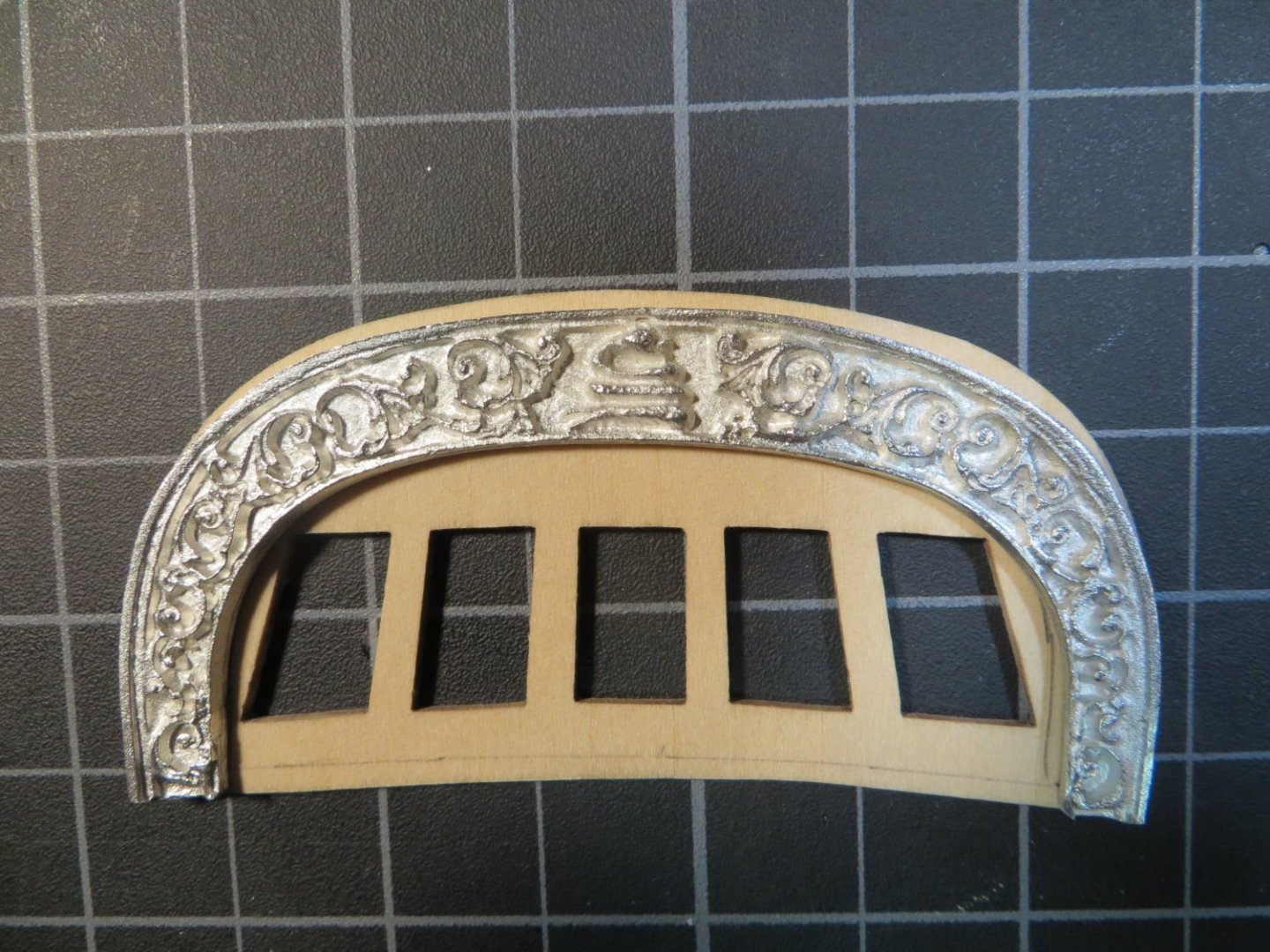
OK Guys! I have a question for you all. My Transom Carving does not cover the top to bottom length of the laser cut transom. It is too short! With fear and trembling I managed to successfully pull the ends of the carving outward, using my hands, to fit the width of the the transom. I used a sanding stick to trim the edges to fit the carving. But, as I'm looking at the carving laying on the transom it's not tall enough!! Should I fit it at the top?? (Which is what I did when I was stretching it open) Then leave the bottom with just the wood? Or should I position it so it's even with the bottom of the transom and sand off the extra wood that shows at the top? Here are pictures showing these 2 options. I've never heard anyone complain about this fit. Has anyone else run into this? Option 1: Carving postioned at the top with wood showing below Option 2: Carving postioned flush with the bottom and extra wood at the top. Note the window openings are a little cramped like this. I would appreciate any input. Also, my windows are significantly smaller than the holes in the transom. I know this is a common problem. I saw one suggestion that if you are planking the transom, which I plan to do, over lap the hole a bit and set the windows against the planks. I think it would be difficult to get an even overlap of planking around each of these windows! Maybe some 1/32" trim on the outboard edges? What did you guys do? Thanks, Ed
-
John, your Rattlesnake is coming along beautifully! I did full length planks on my Bluenose. But I did not use the "Belt" method for trimming the planks width-wise. I forced in some stealers at the end. I am going to try to do a full blown planking job on my Ratt. However, I think I will slip in a full length strake every now and then to help align the butted ones better. At the end, a really good sanding & painting job covers a lot of sins however!! I'm following your build now! Thanks, Ed