HOLIDAY DONATION DRIVE - SUPPORT MSW - DO YOUR PART TO KEEP THIS GREAT FORUM GOING! (Only 36 donations so far out of 49,000 members - C'mon guys!)
×

Ed Ku20
-
Posts
230 -
Joined
-
Last visited
Content Type
Profiles
Forums
Gallery
Events
Everything posted by Ed Ku20
-
 Hi John, the deck planking and hatches look great! I don't think I would change it if it was my model. No one will know the difference and you would need to reinstall too much stuff. It depends on how aesthetically "dis-pleasing" the problem is to me! For example, I was not happy with the way the molding strips looked after I glued them in. I removed them and redid them. 99% of people would never notice, but, I knew I could do better. Your mistake is simply a blueprint mis-read that will not impact the rest of the ship. The end result looks very professional and I see no reason to change it! Just my humble opinion.
 -
Darivs, simply WOW! Now your craftsmanship could qualify for the "ship model hall of fame". Someday, I would love to be able to build a ship with minimal use of paint. Your SoS is beautiful. What is the scale? Thanks for sharing, Ed
-
Hi Darivs, thanks for looking in! Yes, the shipwrights who are building Rattlesnake right now are really good. Lot's of interesting discussions that can be applied to any ship. What model are you building now?
-
I agree, that bulwark sheave is really tiny on the plan. I just made my bulwark sheaves all the same size. They are all larger than the plans. I couldn't make them that small and include the detail I was trying for. I'm not planning to add sails to my Rattlesnake. Since this line is a "tack" it would be attached to the corner of a sail. So, I don't think there will be a line running through the chesstree or that bulwark sheave!
-
Hi John! Yea, yours and mine too! I'm just trying to do the best work that I'm able to do. Aren't we our own worst critics? Happy to provide a bit of insight into how I do things. I'm no expert, and there are probably better ways to do things. But, I always appreciate when builders share their techniques. That's how we all learn and improve! Hi Kenneth! Yes indeed! I'm glad Model Shipways will provide additional materials if you request it. And, I have used that service in the past with my first ship! Thanks everyone for the Likes & encouragement!
-
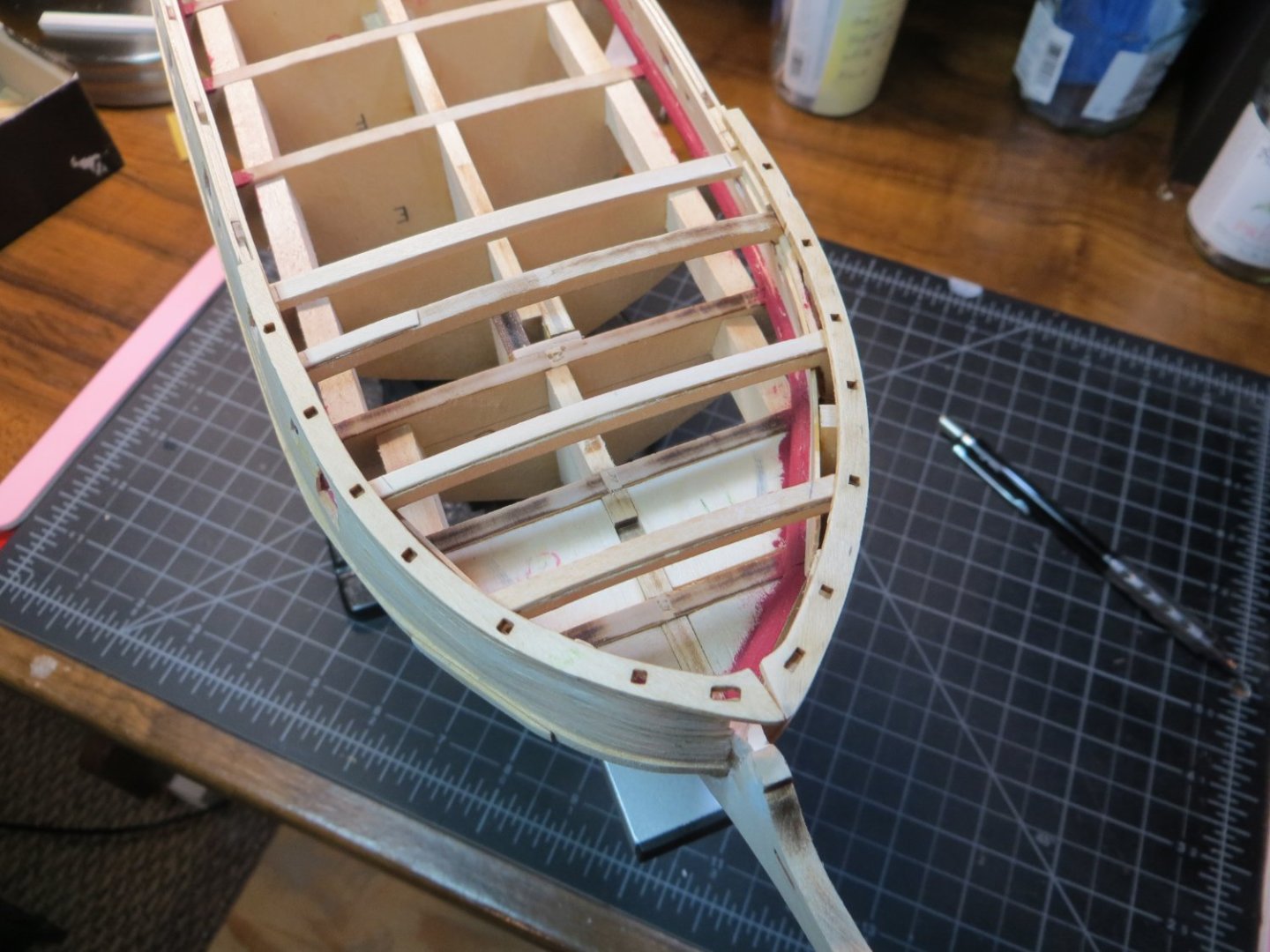
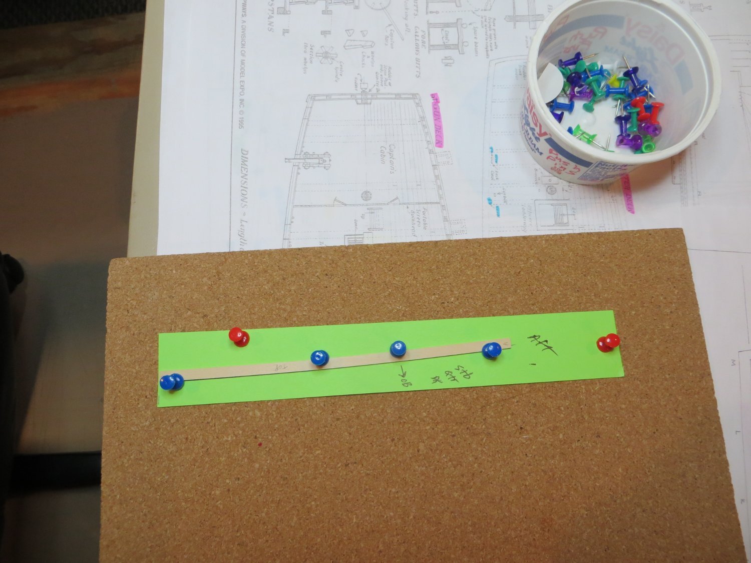
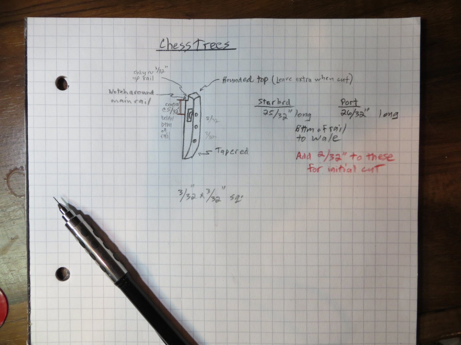
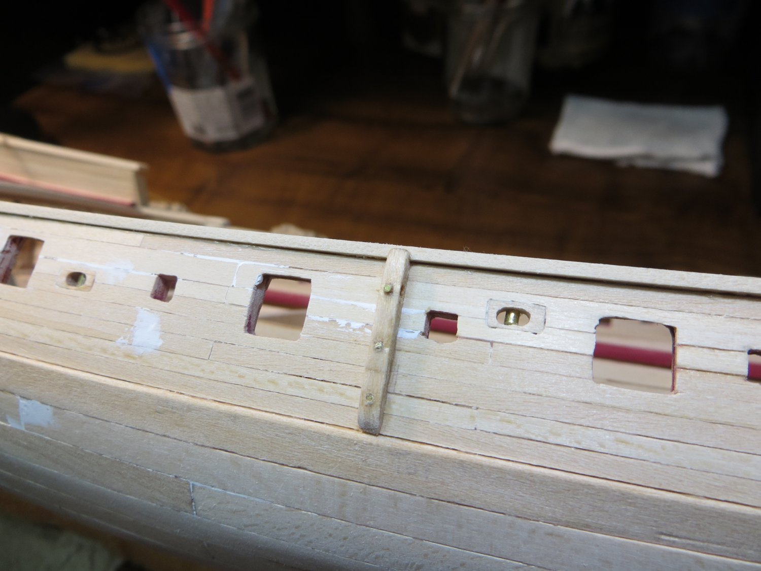
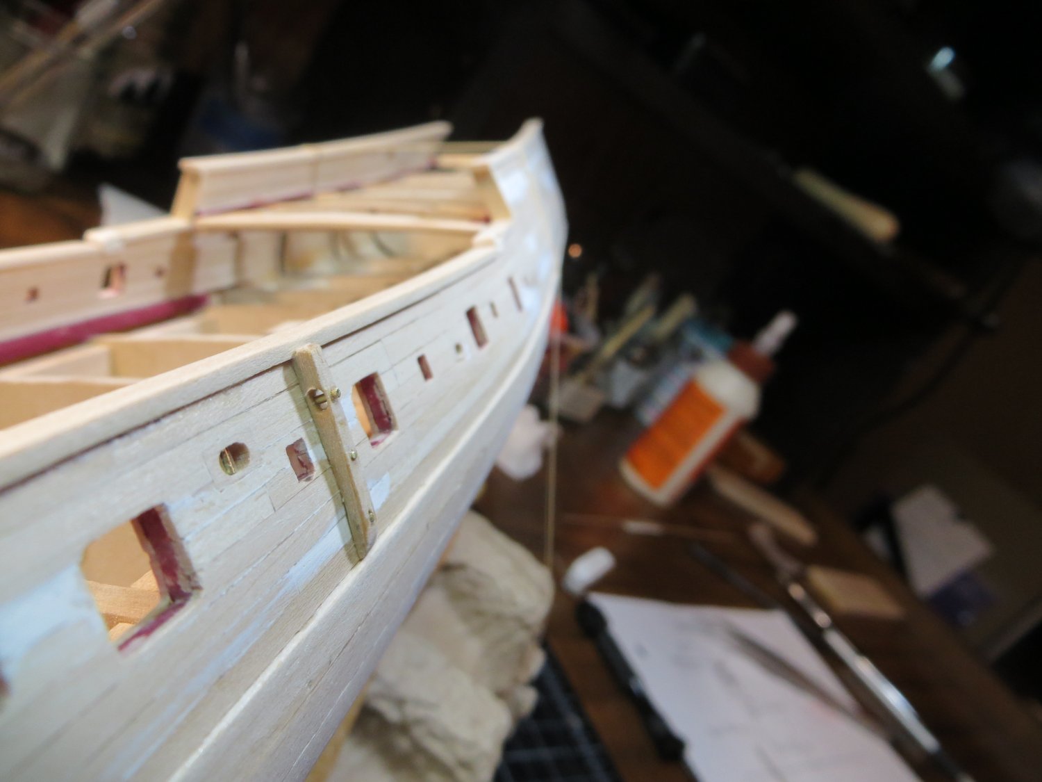
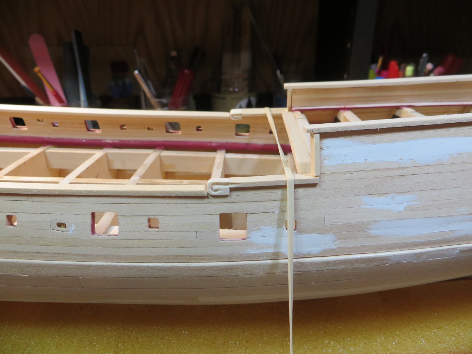
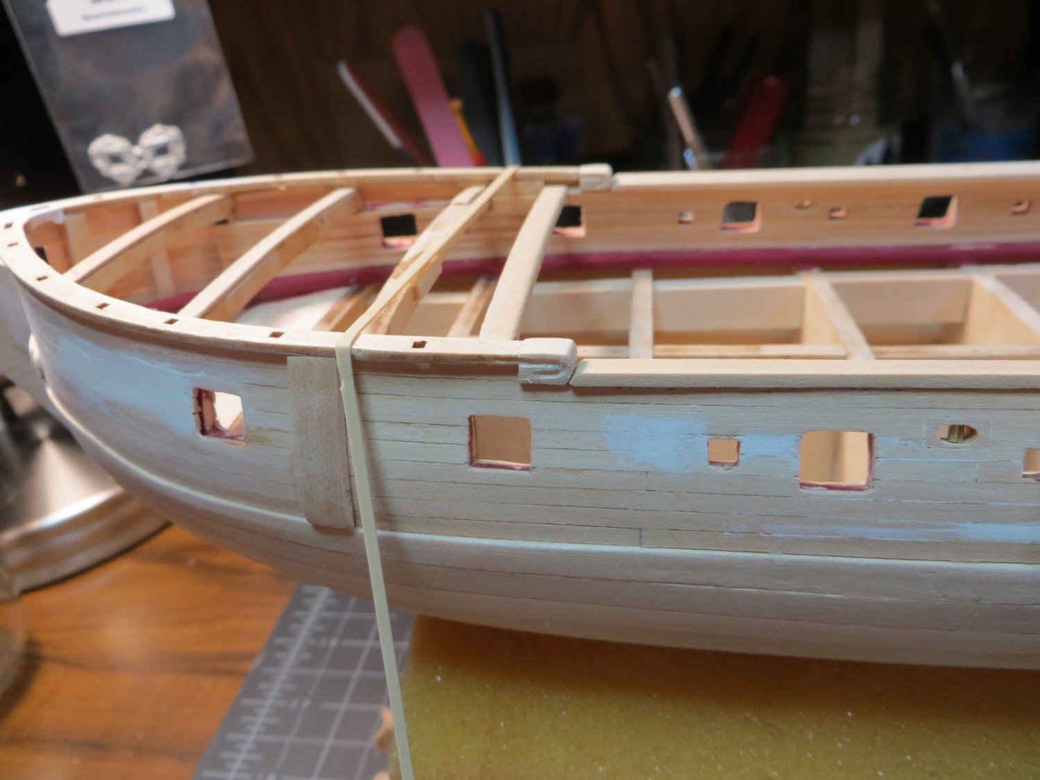
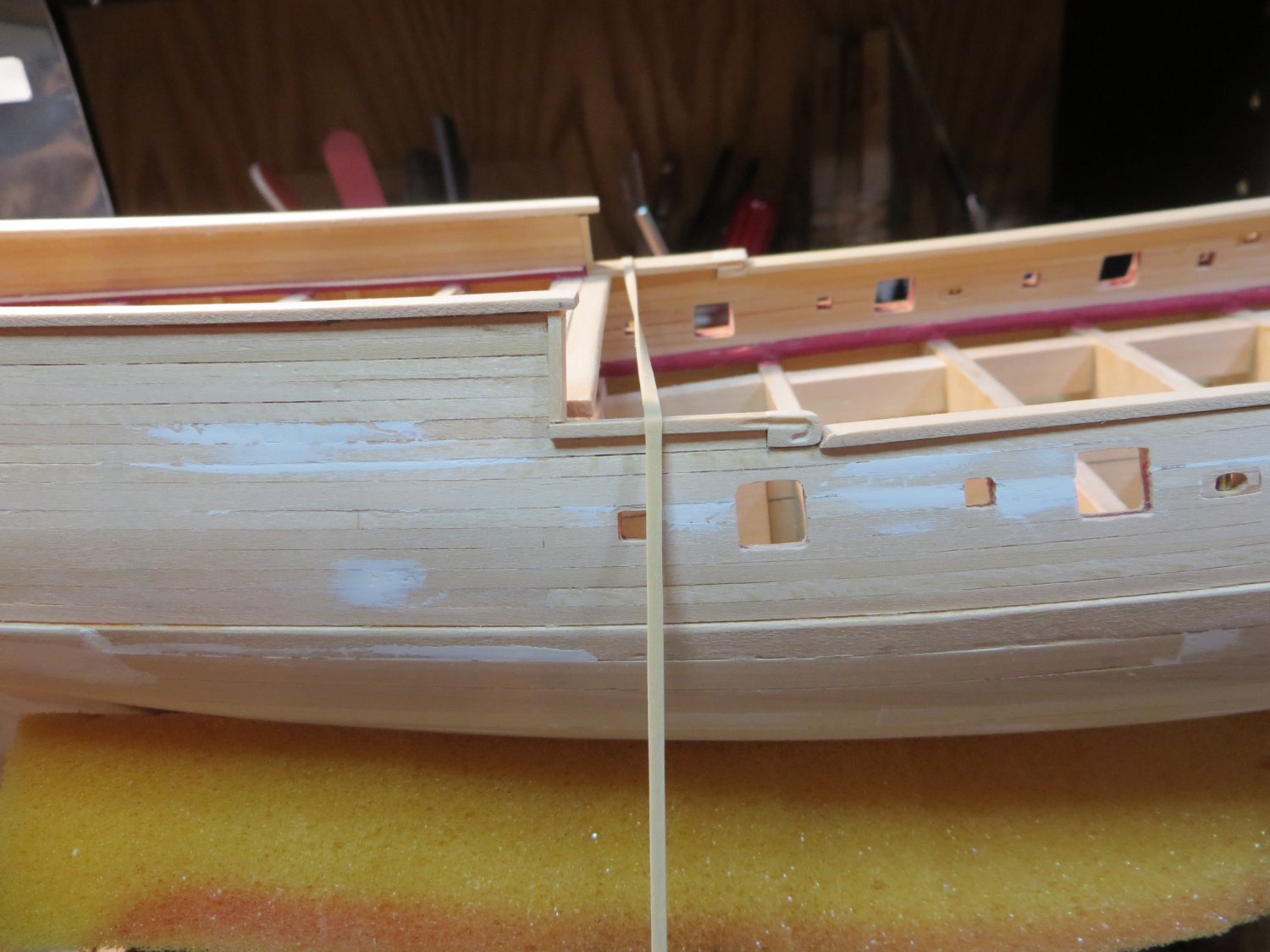
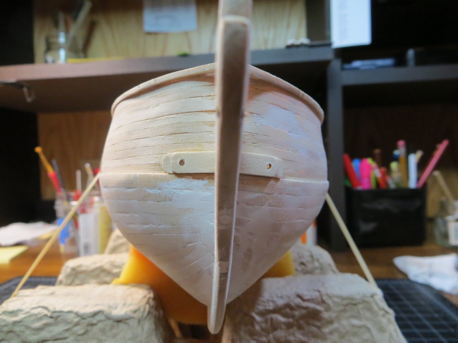
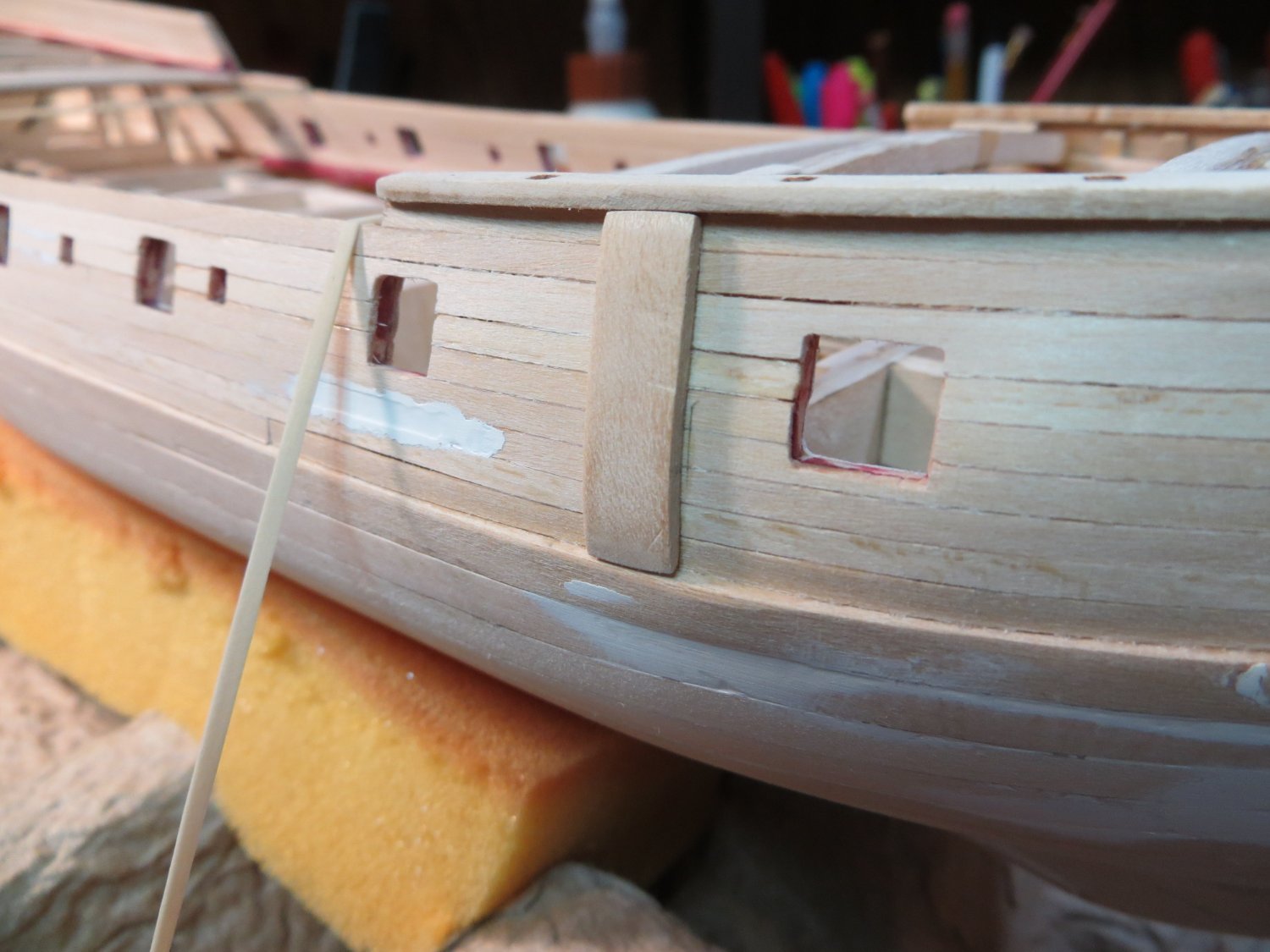
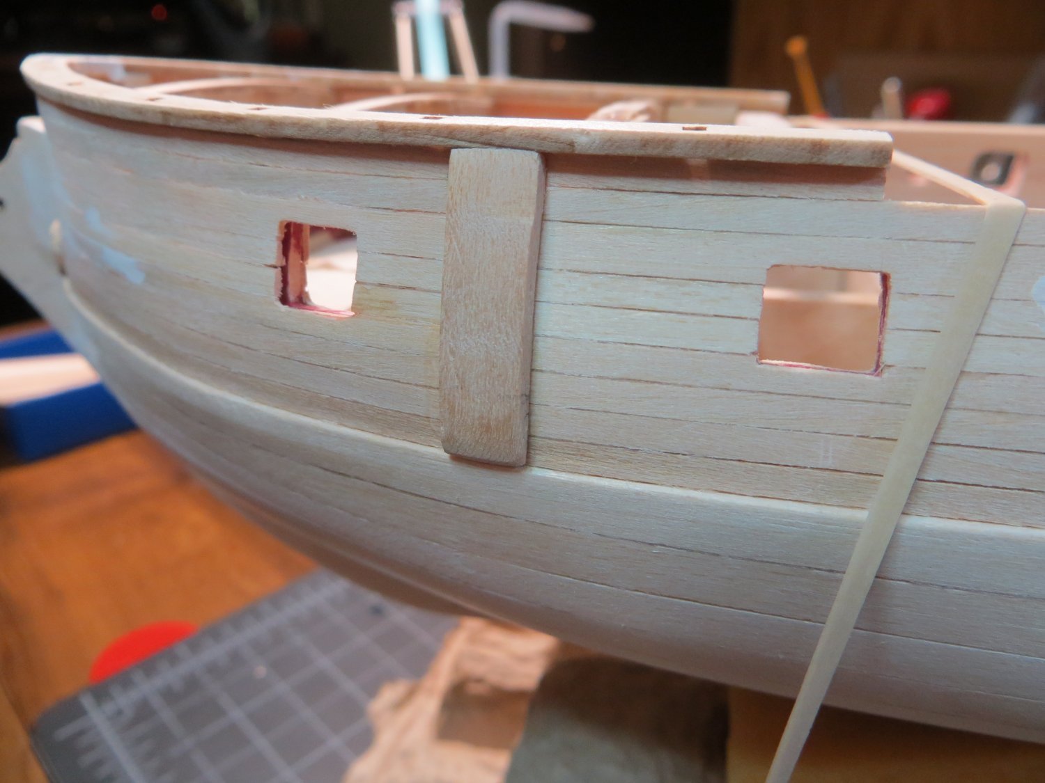
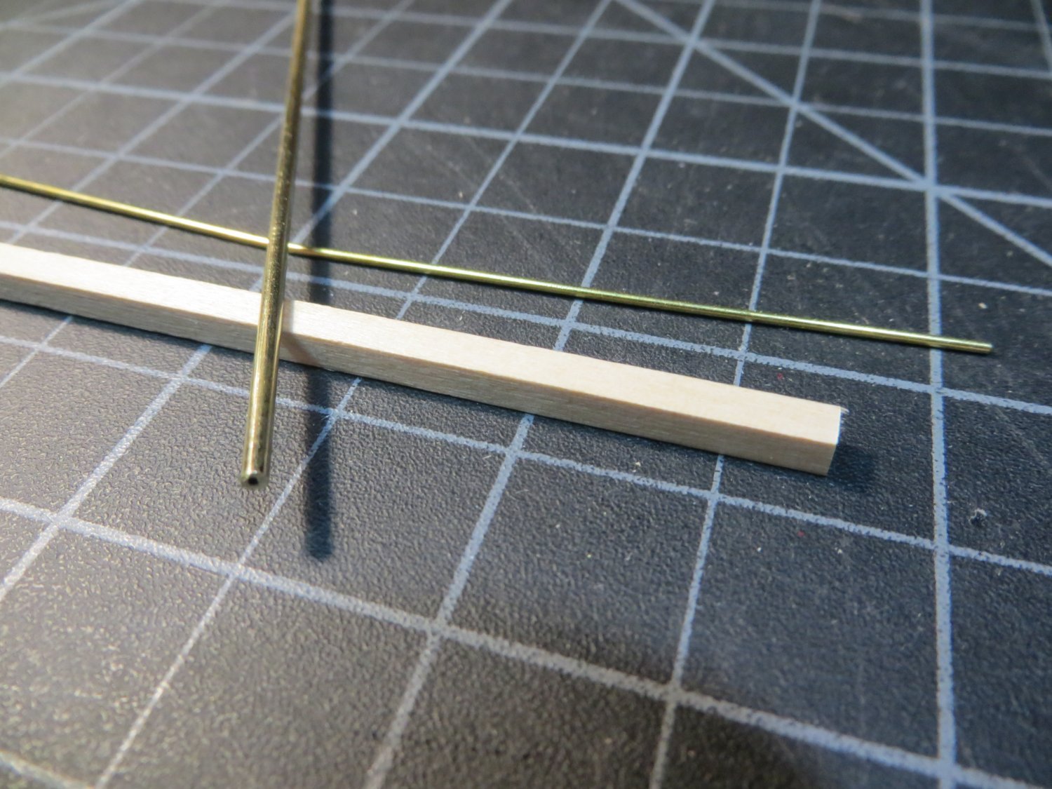
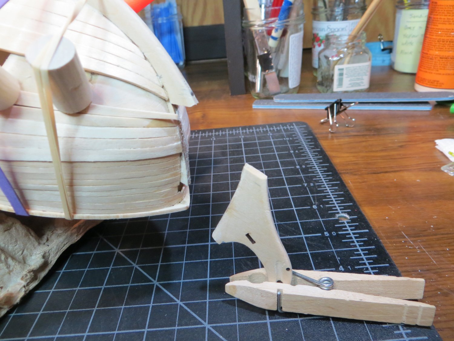
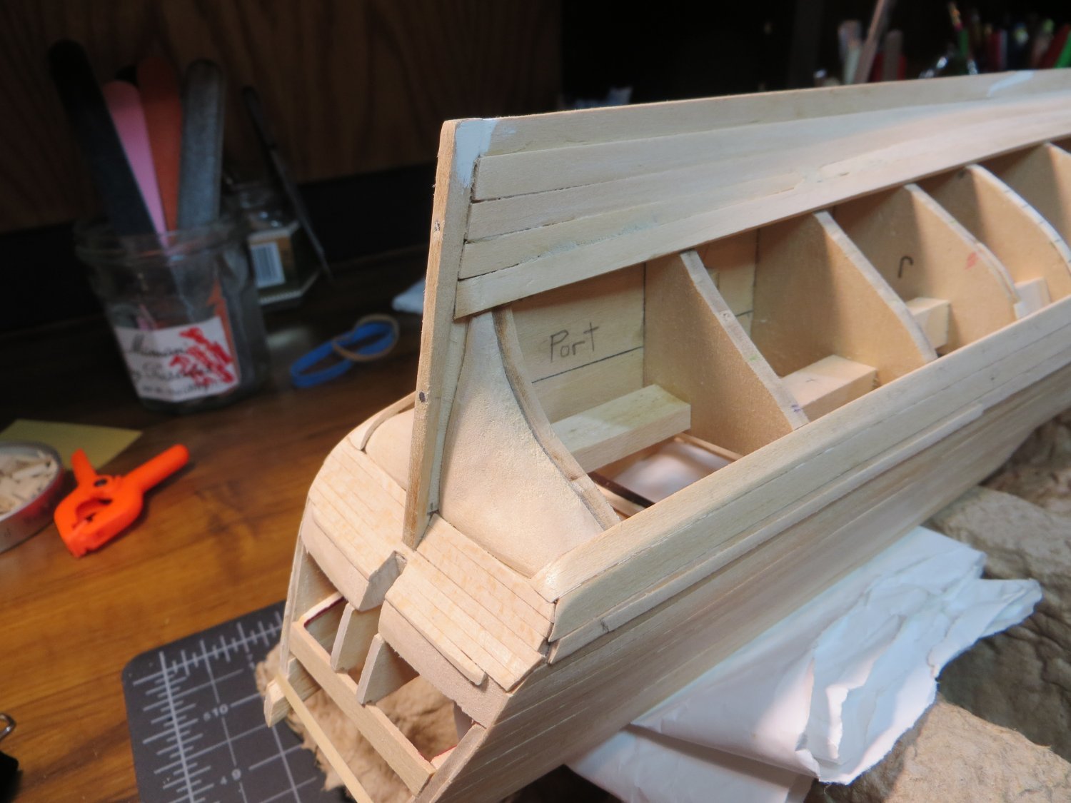
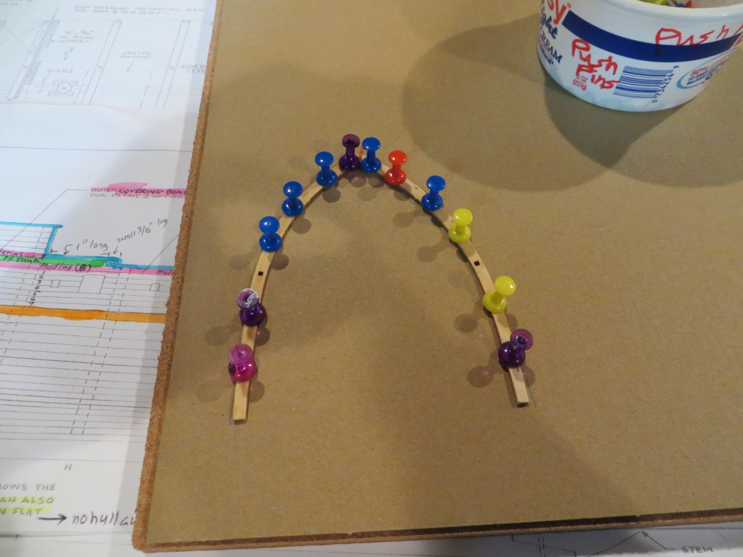
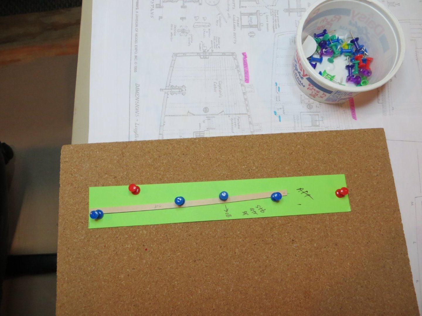
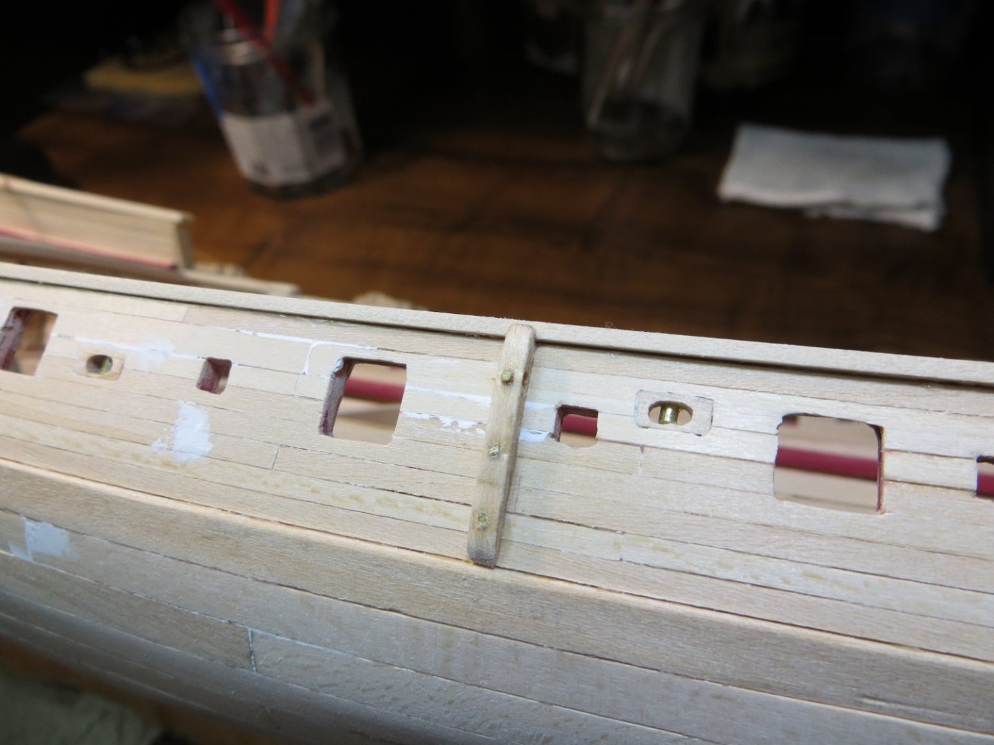
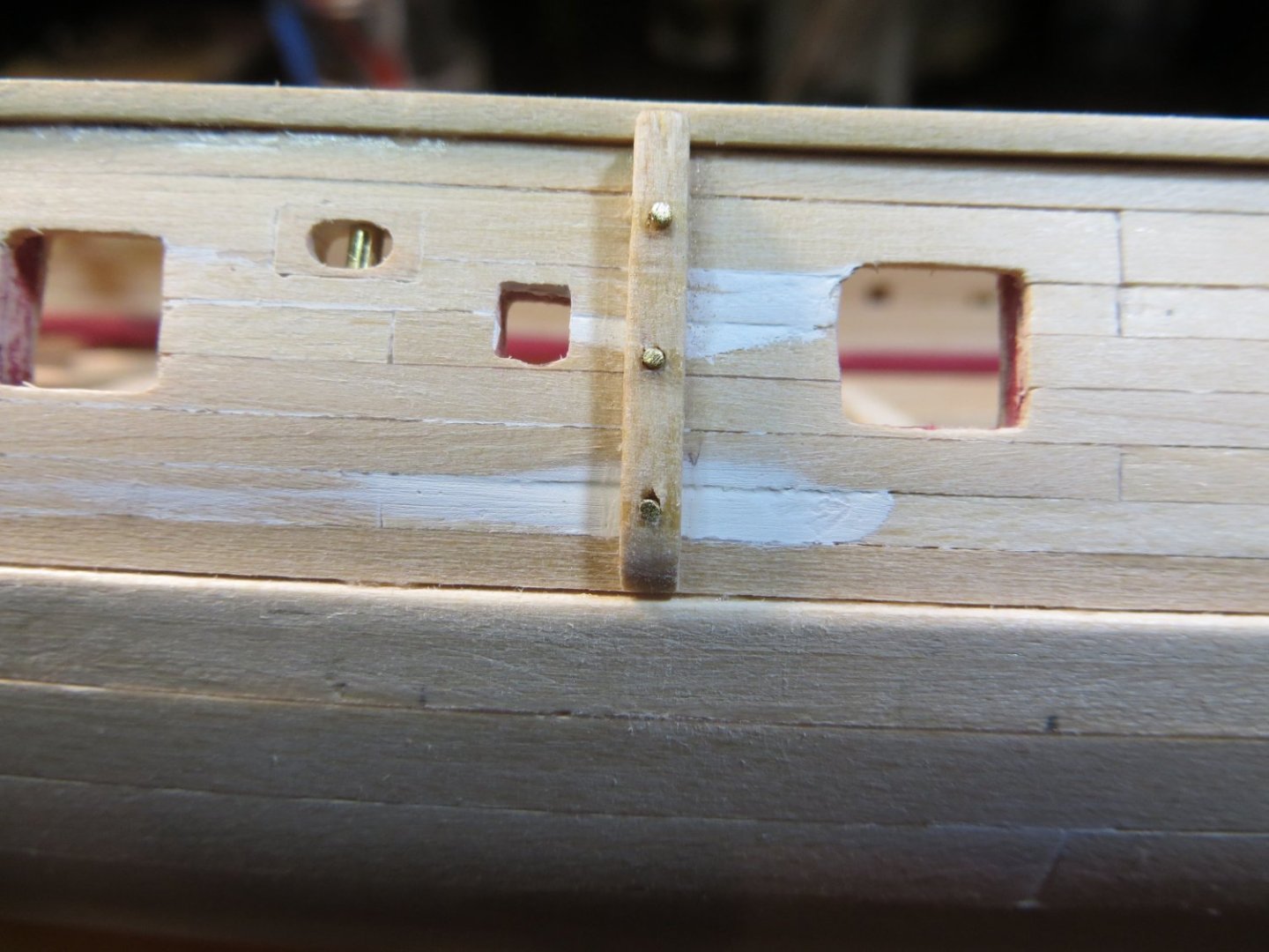
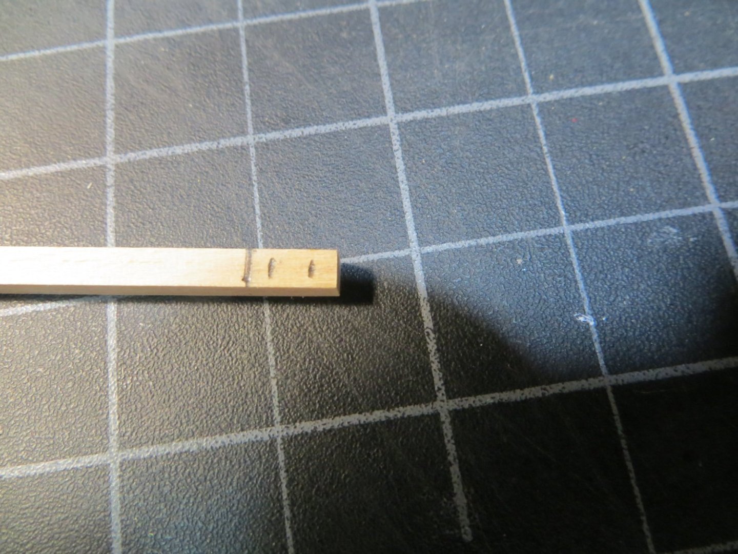
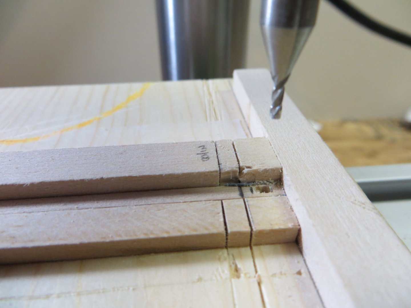
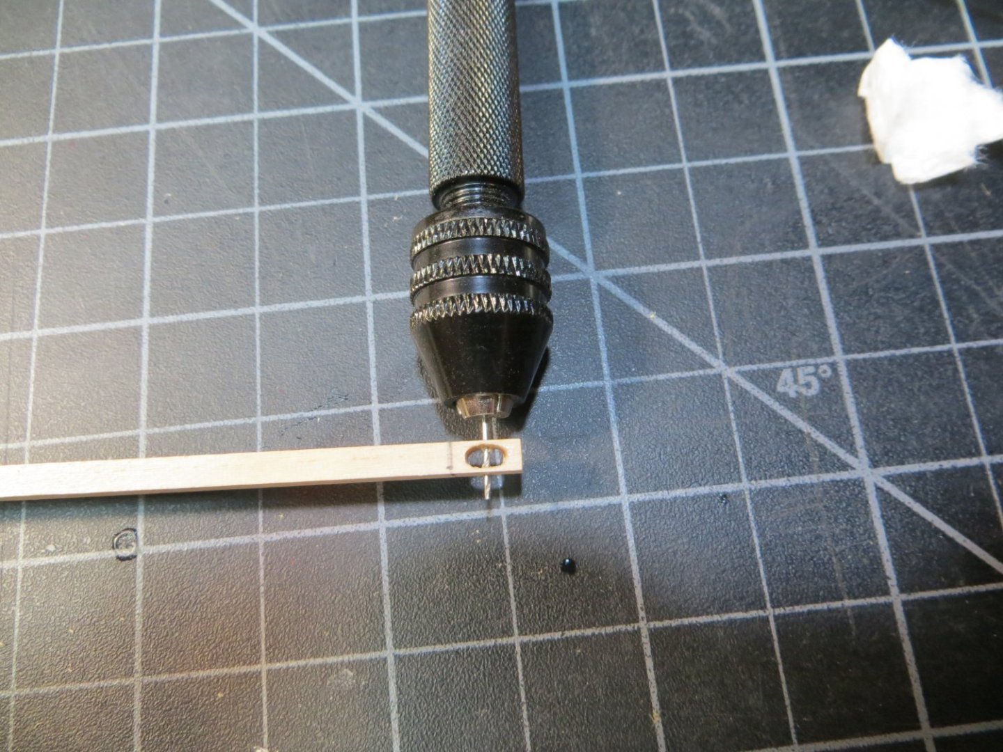
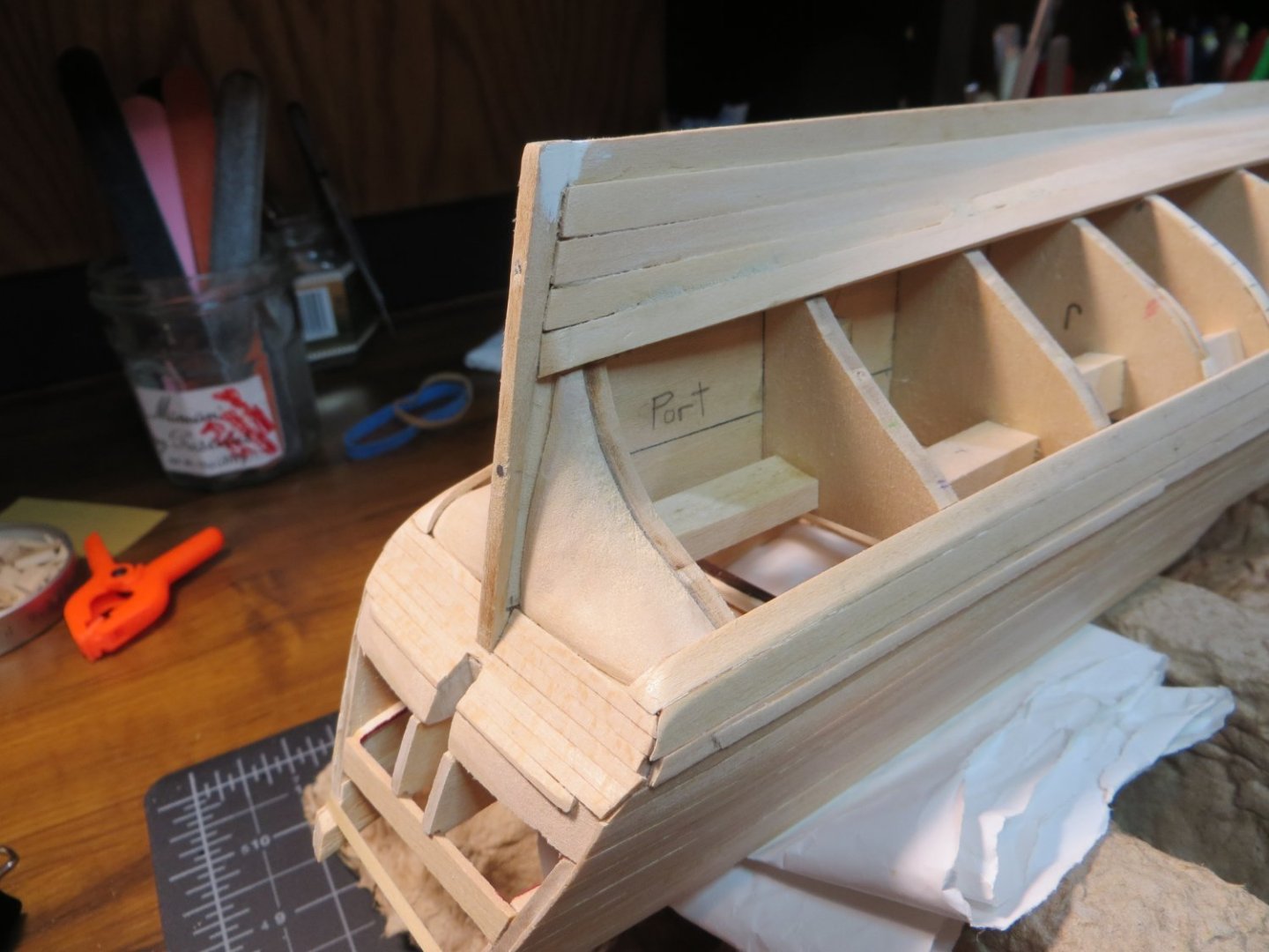
Stage: Hull – Miscellaneous Pieces & Painting Step 28: Carve Scrollwork & Install Gundeck & Quarter Deck Railings I keep changing the order and renumbering my steps! Sorry to confuse anyone who is paying attention! I am adjusting my process according to what makes sense to me at the time! I’m showing the installation of the railings on the Gun & Quarter Decks with this post. Also the Chesstrees. So, let me pick up on everyone’s posts on my question about the overhang of the railings. As Gregory & Kenneth point out, I’m sure that I am one who obsesses too much about minor details! Initially, I installed the railings centered on the bulwarks. This seems to work fine for the gundeck. The molding strip is positioned right below this railing. The 1/16” depth of the molding strip covers the underside of the overhang of the railing. I little sanding might be needed to even it up after the molding strip is installed. But, I did not like the way the centered railing looked on the Q-Deck. It seemed to crowd the space on the Q-Deck. So, I ripped them out and repositioned them to be flush on the inboard side. At least to my eye, this looks neater and cleaner. Below are some pics of my progress. I traced the curvature of the railings and then soaked and pinned the 1/16 x 3/16” stripwood on corkboard to get the proper edge bend. These are the same stripwood as the lower hull planks. They are then laid flat over the bulwarks. Port Side showing the scrollwork carving. I used a fine pointed burr in my Dremel to carve the shape into both sides of the wood. Various mini files were used to clean it up. This is my first attempt at doing this kind of carving. It was a slow, tedious process that involved more than a few additions to my scrap pile! I tried to extend the carved line into the board adjacent to the scroll piece to create a little personal character! Port Side showing the scroll coming off the Focsl cover board. Starboard side at Q-Deck Step 27: Making/Installing the Chesstrees There were two sub-steps left in Step 27. The Chesstrees overlap onto the sides of the railing, therefore these needed to be completed after the railings were installed. The other step is the Kevels. These are on the inboard side of the bulwark, so they need to be done after the decks are installed. I moved the Kevels down past that step. The Chesstree is similar to the Sheaves. However, it is built into a piece of stripwood that is attached to the outside of the hull. Based on my measurements, I selected a piece of stripwood 3/32” x 3/32” square. It is long enough to fit between the main rail and the wale. It must be shaped to match the curvature of the hull between these two points. Near the top it contains a sheave that is used for the mainsail tack line. The sheave hole must accommodate a 0.03” rigging line. The top of the Chesstree is rounded and notched on the inside so it can overlap the gundeck rail. The bottom is tapered into the wale. I started out by sketching the dimensions of the Chesstree and all it’s elements as shown below Starboard side Chesstree. I used 3 pieces of brass rod to simulate the bolts that hold it in place The hole for the sheave was drilled into the stripwood similar to the bulwark sheaves. Due to the smaller size, for these, I decided to just use the brass rod alone to simulate the sheave. I soaked and bent the wood to match the curvature of the hull. Chesstree, Port Side My next steps include installing the molding strips & covering boards, preparing the quarter badges and fashion pieces. This will require more carving and using the new Artesania scrappers that I just purchased to carve the shape of the 4 strips. As always, I appreciate your feedback. Thanks, Ed


-
Very fine job Dave! Congratulations on completing your Bluenose. Good Luck on your next project! Best regards, Ed
-
Kenneth & Dave, thanks for your feedback. I will shoot for the middle!
-
Hello Fellow Snake Builders! I have a question. I'm getting ready to do the quarter deck & gundeck railings. I want to make sure I'm reading the plans correctly. It looks like the railing overhangs the outboard side, but is mostly flush with the bulwarks on the inboard side. I can see the outboard overhang on everyones pics, but on the inboard side it's hard to see. What did you all do? Thanks, Ed
-
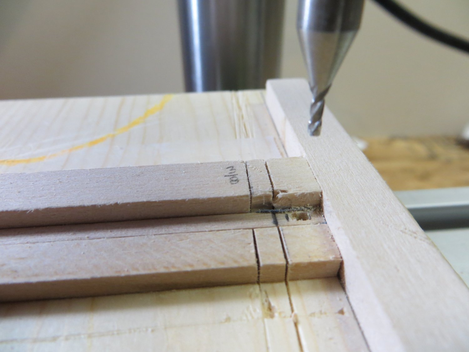
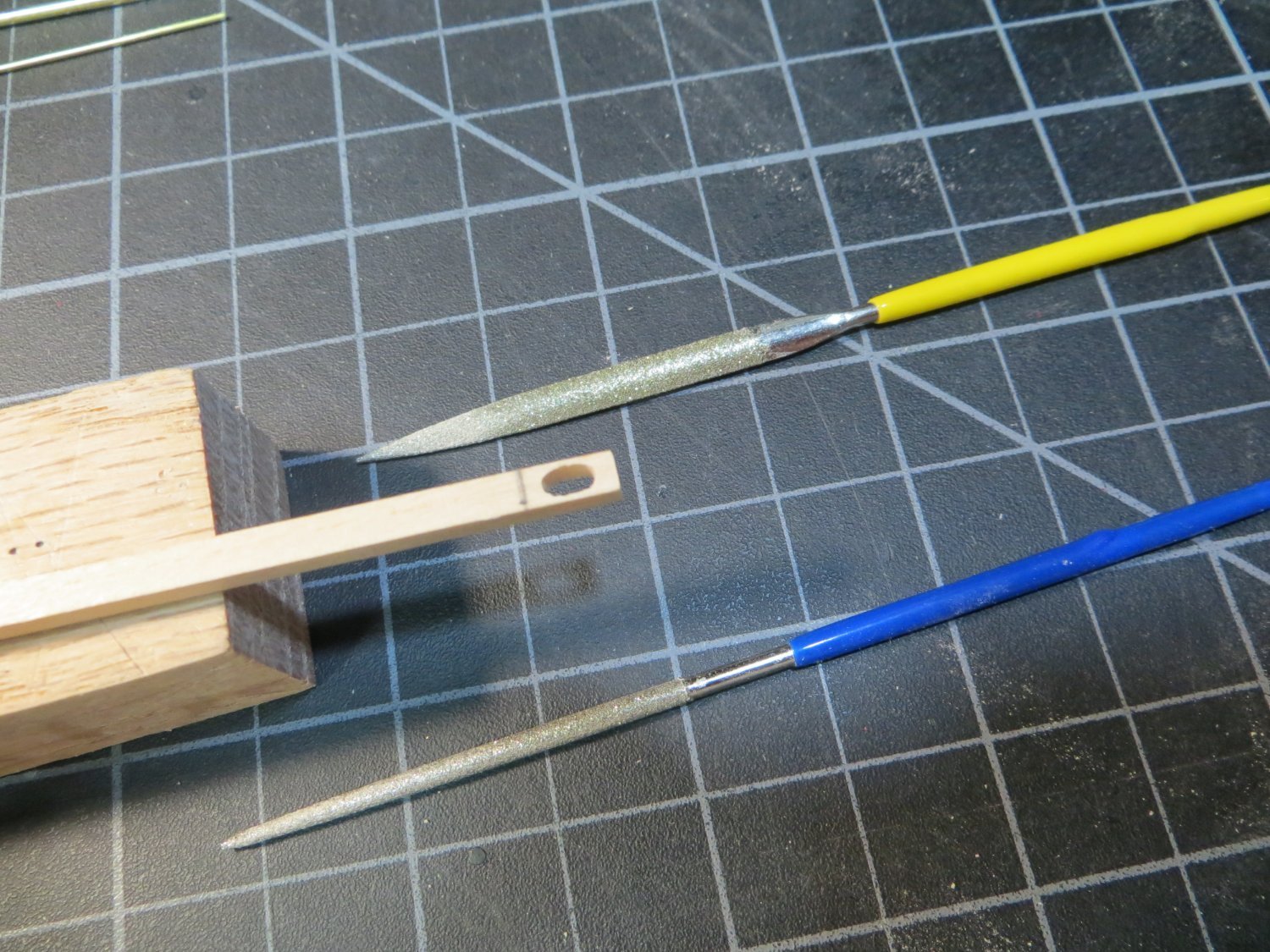
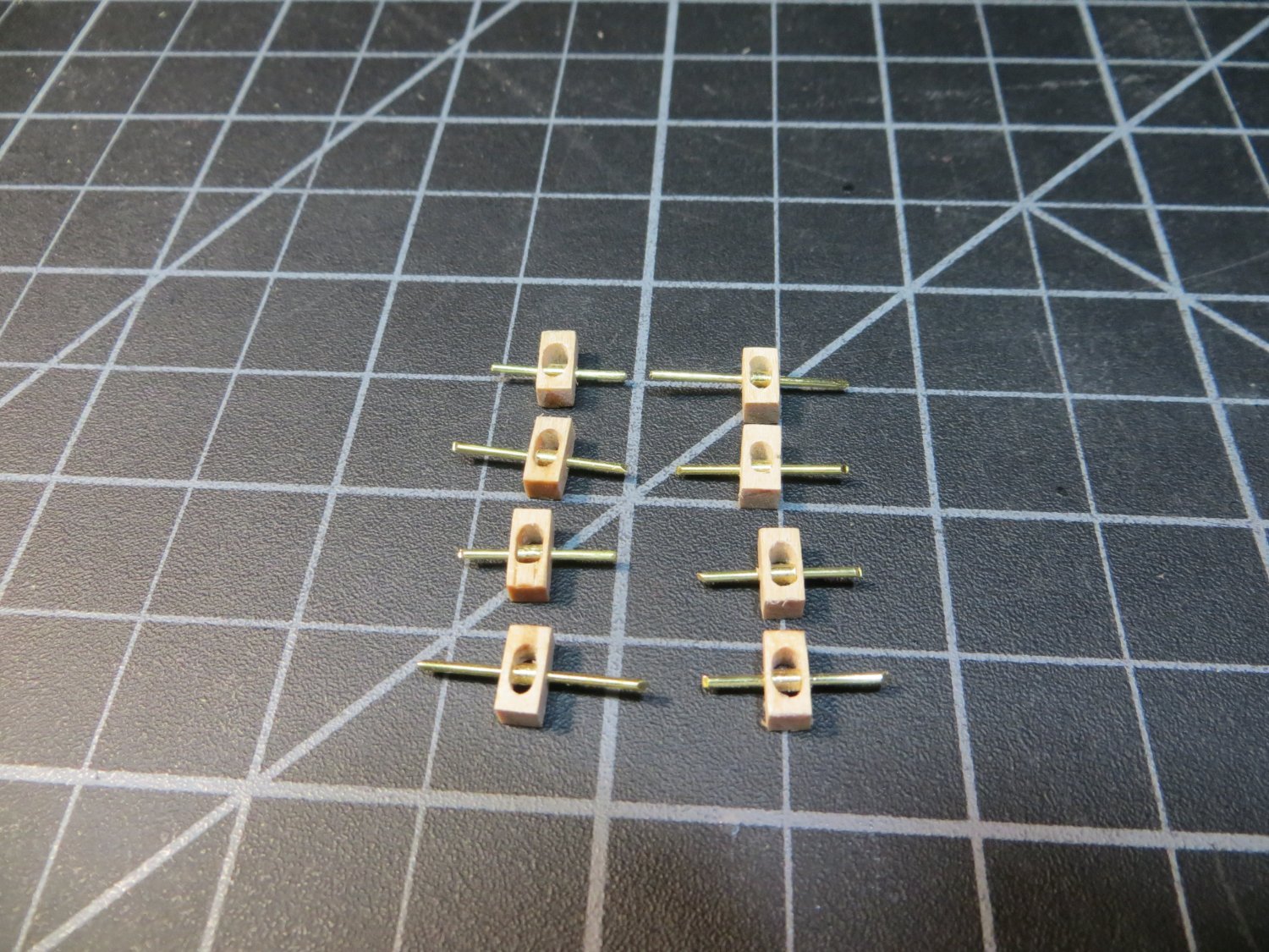
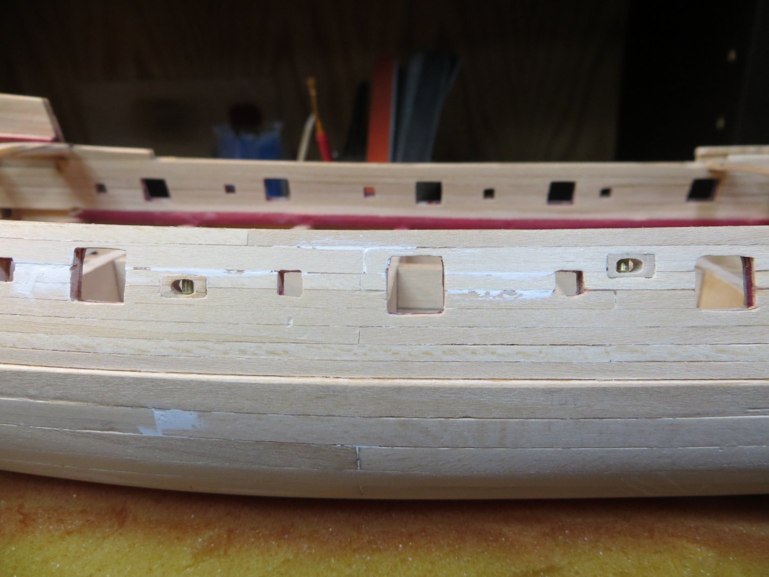
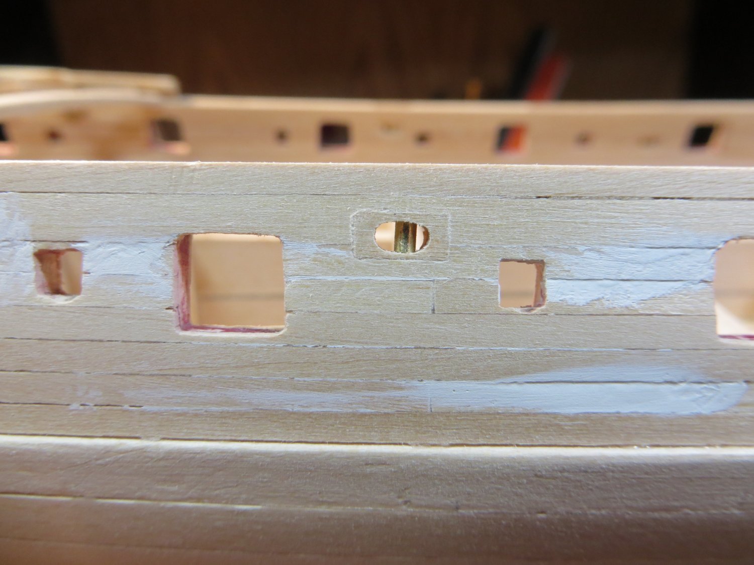
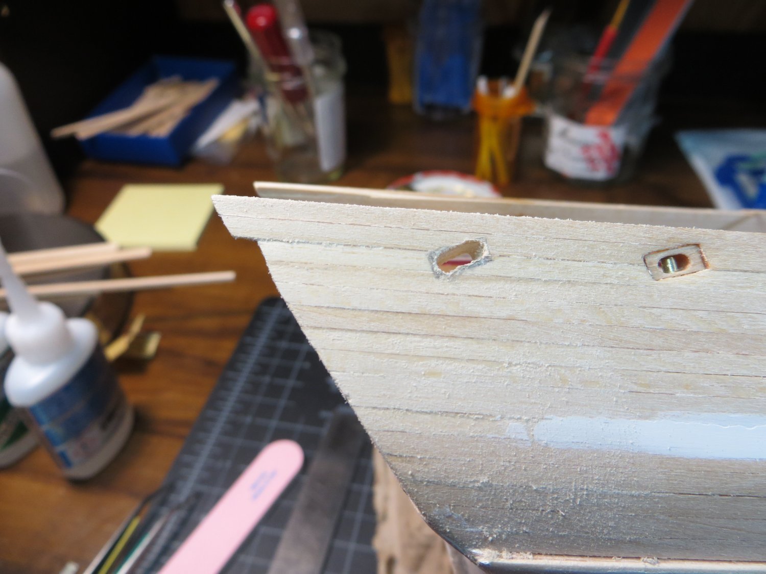
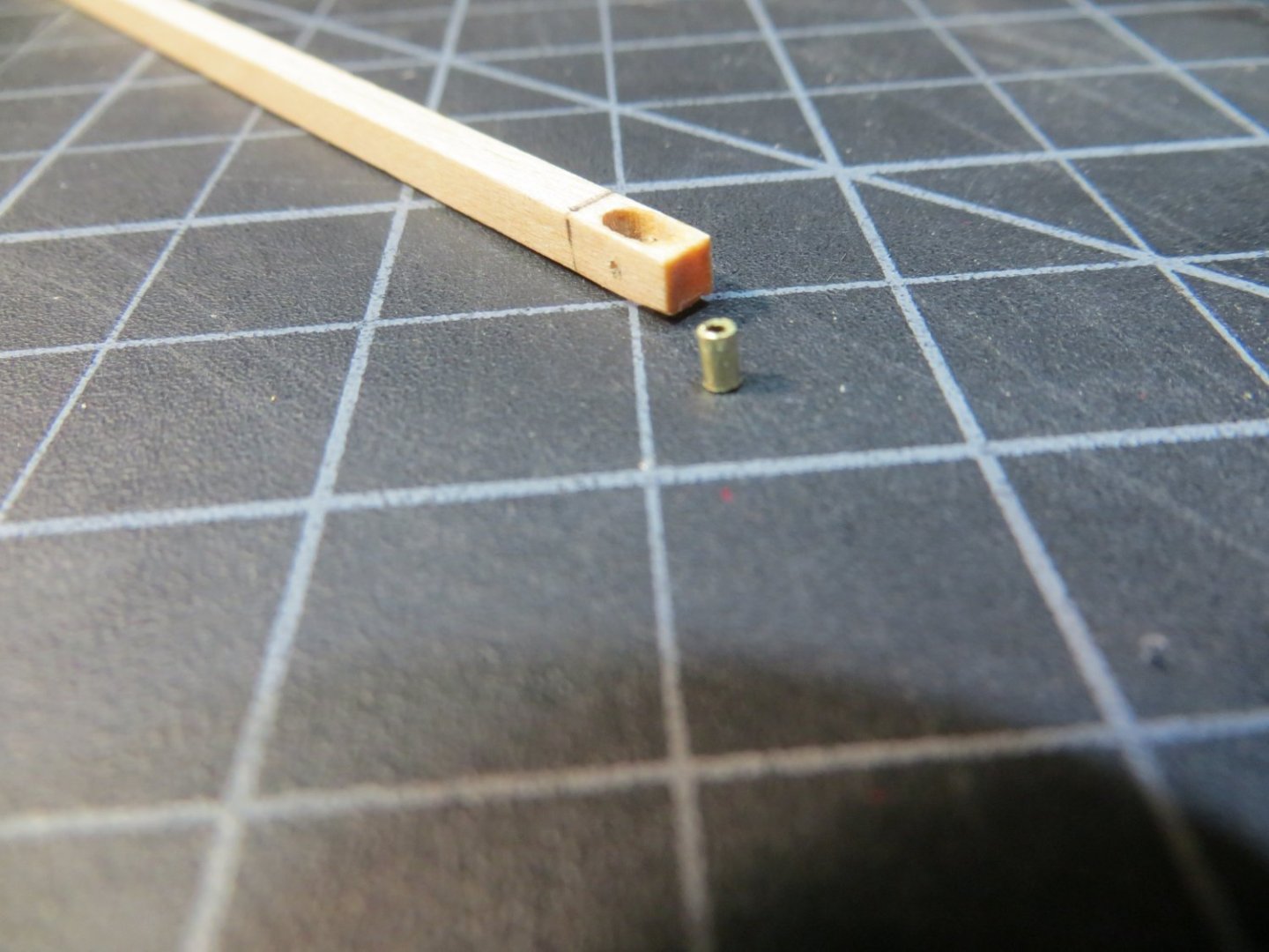
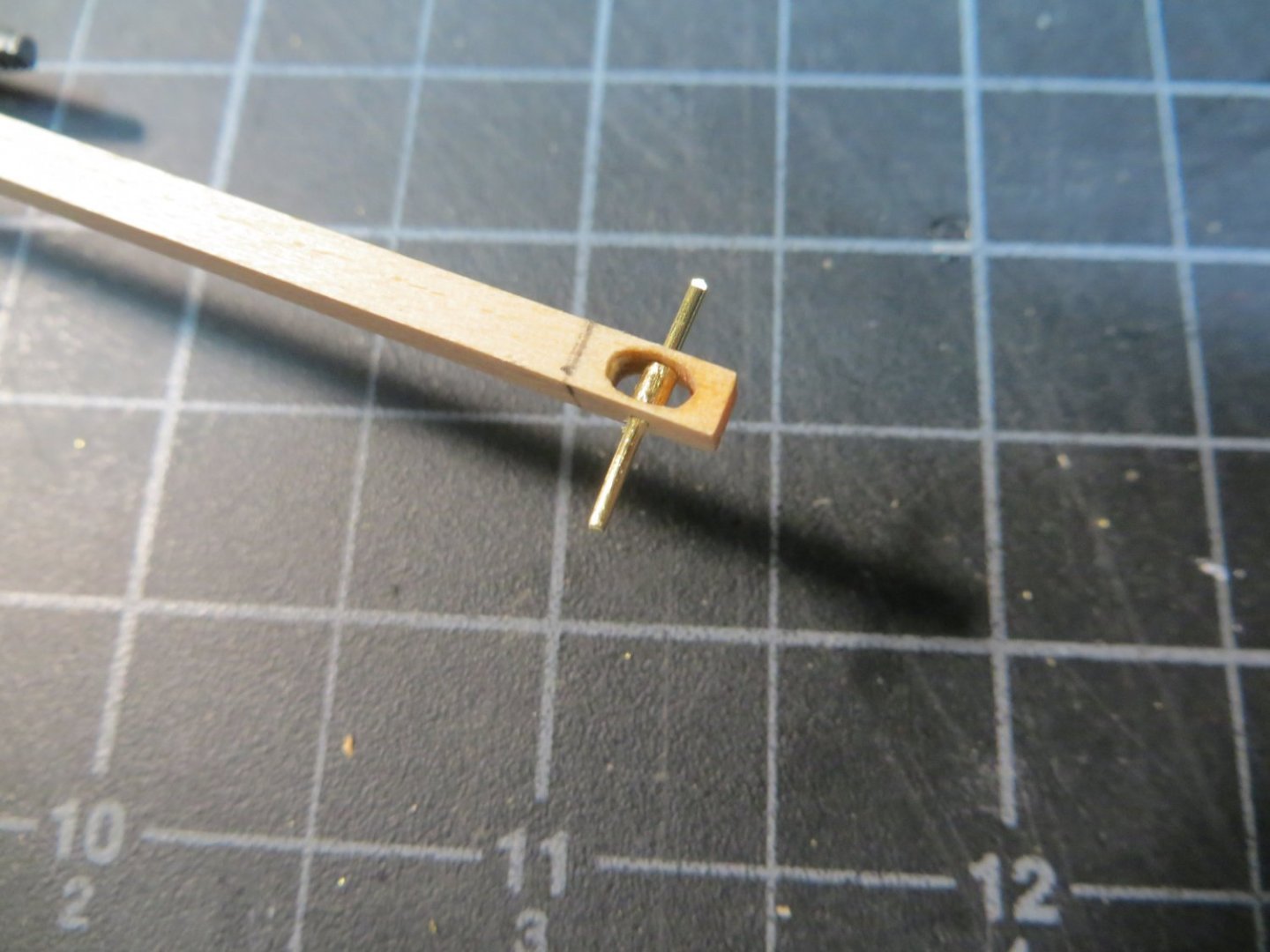
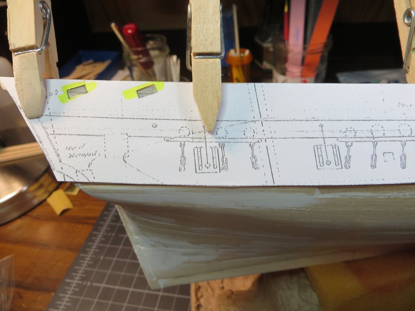
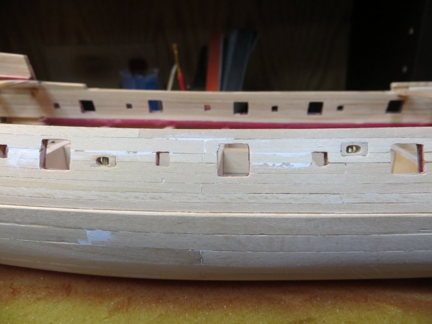
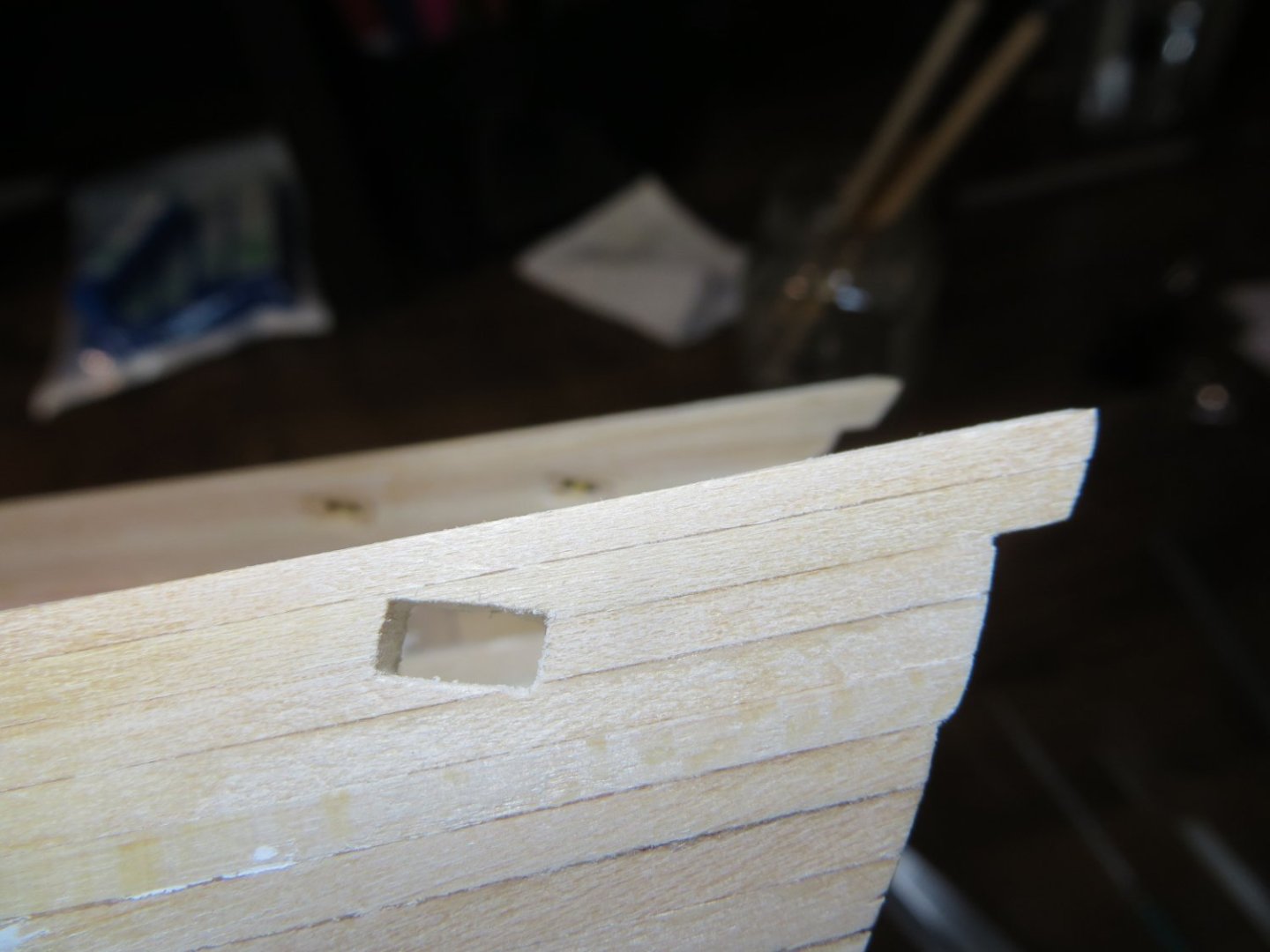
Stage C Hull – Miscellaneous Pieces & Painting Step 31: Add Anchor rope holes & anchor bumper pads, Chesstree, Kevels & Sheaves to hull I gave some thought to the order of the steps for the various tasks and pieces that need to be added to the hull at this time. I ended up changing things around from my original spreadsheet. When I took into consideration how some of these pieces needed to fit in between the molding & covering strips, I made adjustments. The Chesstree will be installed after the railings and moldings are finished. The Kevels will be dropped down to when the deck is finished. These are on the inboard side of the bulwarks. Step 26: Drill holes for Mounting the ship – it is important to drill the holes for the brass mounting posts now. It is much more difficult to turn the ship over once other parts are installed. I drilled holes using the pin vise gradually increasing in size until I got the proper diameter hole. The hole size needs to be small enough to allow the threads on the screws to bite into the wood for a strong fit. Step 31a: Anchor Pad – use ¼” x 1/16” piece of stripwood. This piece fits between the focsl covering board & the wale. I had to soak and bend the bottom half of the board with the big curling iron to fit the curvature of the hull. I clamped it in place and allowed it to dry fit to the hull before gluing. After the dry fit, I was able to glue the board in position with just my fingers holding it in place for a short time. Step 31b: Anchor Rope holes – these are made from 2 overlapping pieces of stripwood 1/32” x 3/16”. This assembly sits above the Wale and butts against the stem. The longer/bottom board, by my measurement is about 9/16” long. The shorter/top board is 15/32” long. First, I shaped the rounded edges on the outboard side before gluing the 2 pieces on top of one another. Then I beveled the inboard side for a close fit up to the stem. In order to pre-fit the pieces to the bow curvature, I soaked the assembled wood pieces and rubber banded them to a glass jar that matched the curve of the bow. I let this dry overnight. The pieces were glued to the hull. The holes for the anchor rope were drilled with the pine vise parallel to the center line of the ship. The rope holes go thru both boards and the upper bulwark of the hull. NOTE: This hole needs to be outboard of the head rail that will attach just inboard from it. Step 31c: Sheaves – there are 8 sheaves positioned around the upper hull. They fit in holes drilled through the bulwarks. Rigging ropes pass through the wooden sheave and over a pulley inside the sheave. They are tied off on a cleat or belaying pin on the inboard side of the bulwark. I could not find any build log that showed how to make these. Dimitry Markov had some good pictures in his Snake log. But, no “how-to”. Therefore, I am going to post a “How-to” on how I made my sheaves. Hopefully someone will find it useful! I do not have any special knowledge and limited skill. But, I’m willing to share my experience with a first-time attempt at something new! FYI, this required a lot of trial, error and scrap generated! The tricky thing with the sheaves is they can have a lot of detail in a very tiny piece. It looks like most builders just drill a hole through a rectangular piece of wood. But I remember something Dave (CPDDET) told me. “In my opinion, I would sacrifice a bit on exact dimensions in order to produce better detail on the workpiece.” So, I made mine somewhat larger than the blueprints showed. I used a 1/8” x 1/8” square piece of stripwood and made them ¼” long. In hindsight, I could have used something a little wider to cover the width of the bulwark. Materials Used: 1/8” x 1/8” stripwood, 1/16” diameter brass tube, 1/32” brass rod I marked off the ¼” length on the end of the wood and 2 guide lines where I will drill out the center To make the sheave hole, I attached an old jig to the X-Y table on my drill press to hold the piece securely. This jig has a 1/8” space where I laid the strip into the gap. I drilled a couple of 1/16” holes side-by-side between the marks on the strip. The hole was cleaned up using the mini-files shown below Pencil marks were centered on the top and bottom and a pin vise was used to drill a hole for the rod. I found that I got a straighter, better aligned pair of holes if I flipped the piece over and drill at the mark on the other side, rather than drill straight through from the first side. The sheave is made using a short length of tubing. For accuracy, I cut the tube with a razor saw and miter box. This tube is tiny. Some filing was required to get the piece to fit into the sheave hole. The tube is slipped into the sheave opening and a piece of brass rod is used to hold it in place. I will cut off the ends later when I install the assembly into the bulwark. The assembled piece is cut off the strip when done The batch of 8 sheaves are ready to install on the ship’s bulwarks I photocopied the plans and cutout the part showing the location of the sheaves on the gundeck and quarter deck. I cut a hole in the paper to fit my sheave. I positioned the cutout on the bulwark and penciled in the location on the side of the ship. I started out by using a carving bit in the Dremel to make the initial cut through the bulwark. Next, mini-files were used to slowly expand the hole until the sheave fit snugly in place. Here is one of the holes after filing and sanding. Completed installation for the starboard side sheaves at the gun deck. Also, a close-up of the first sheave. Pics showing the sheaves on the starboard and port sides. I’m not happy with the forward port-side Q-Deck sheave. The space between the inboard and outboard bulwarks is hollow in the spot. The planks were wobbling as I was cutting and the hole ended up off size. I should have inserted a piece of wood filler to make it more solid. I’m hoping that a little filler around the edges will make it look less conspicuous! The starboard side turned out better, as I was cognizant of the problem by then. So, that's how I made the sheaves for my Rattlesnake! I welcome your feedback on the sheaves! The next step is installing the railings on the quarter & gun decks. I already carved the fancy scrollwork for the transitions to the gundeck. I purchased a couple of the Artesania-Latina Micro-Shapers for the molding strips. I’m also thinking about using them to put a curved edge on the railings. I’m going to do some experimenting with that. Thanks, Ed


-
Decorative trim/rail
Ed Ku20 replied to DaveBaxt's topic in Building, Framing, Planking and plating a ships hull and deck
Hi Dave, Thanks for your input! Did you purchase direct from Artesania or somewhere else? Which size or sizes did you get? Allan, I didn't mean an actual chisel! I've seen people put grooves in a used Exacto chisel blade. The one drawback I see to that is, you pretty much have to custom make one for different shapes & sizes of wood you are working on. Thanks for the tips! -
Decorative trim/rail
Ed Ku20 replied to DaveBaxt's topic in Building, Framing, Planking and plating a ships hull and deck
Hi All, I am working on the railings and molding strips for my Rattlesnake build. I was going to make my own by using the Dremmel on a chisel blade. The Artesania scrappers look like an awesome tool. I have two questions: 1. Could these be used on wood that is in fractional dimensions? For example could you use 2 x 5 mm scrapper on a 1/16" x 3/16" piece of strip wood? Not a perfect fit, but could it work? 2. Or, if not, does anyone supply a similar product in english fractional dimensions? Thanks, Ed -
Hi John, I started working on the cap railings. First off, I discovered I really stink at carving! I really like the way your scrollwork on the deck transitions turned out. What did you use to carve yours? I bought some micro-gouges, but cannot seem to get anything that looks satisfactory with such a small piece of wood. I'm also frustrated because I can't find the right size piece of stripwood. They don't make one that's 3/16" x 1/8". That's what I need to reach from the gundeck at the step-down that's forward of the quarter deck. Yours appears to be a bit taller, but could be the camera angle. Hope you don't mind me seeking some guidance from you on this topic! Thanks, Ed
-
So Kenneth, is your point that those beauty marks don't need to be sanded away completely. Leave some marks for character? Thanks, Ed
-
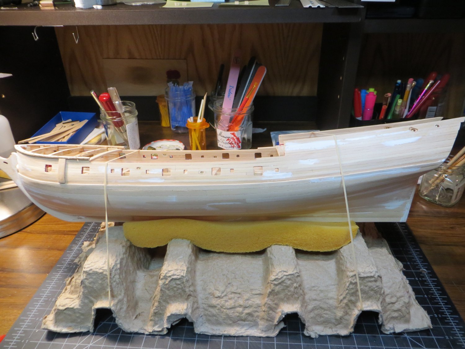
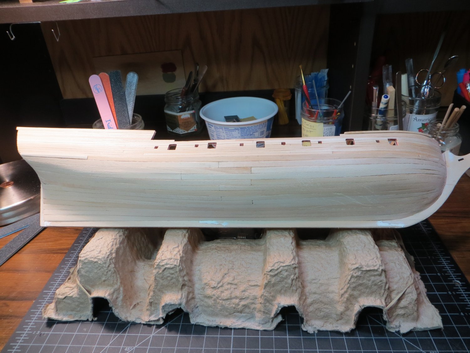
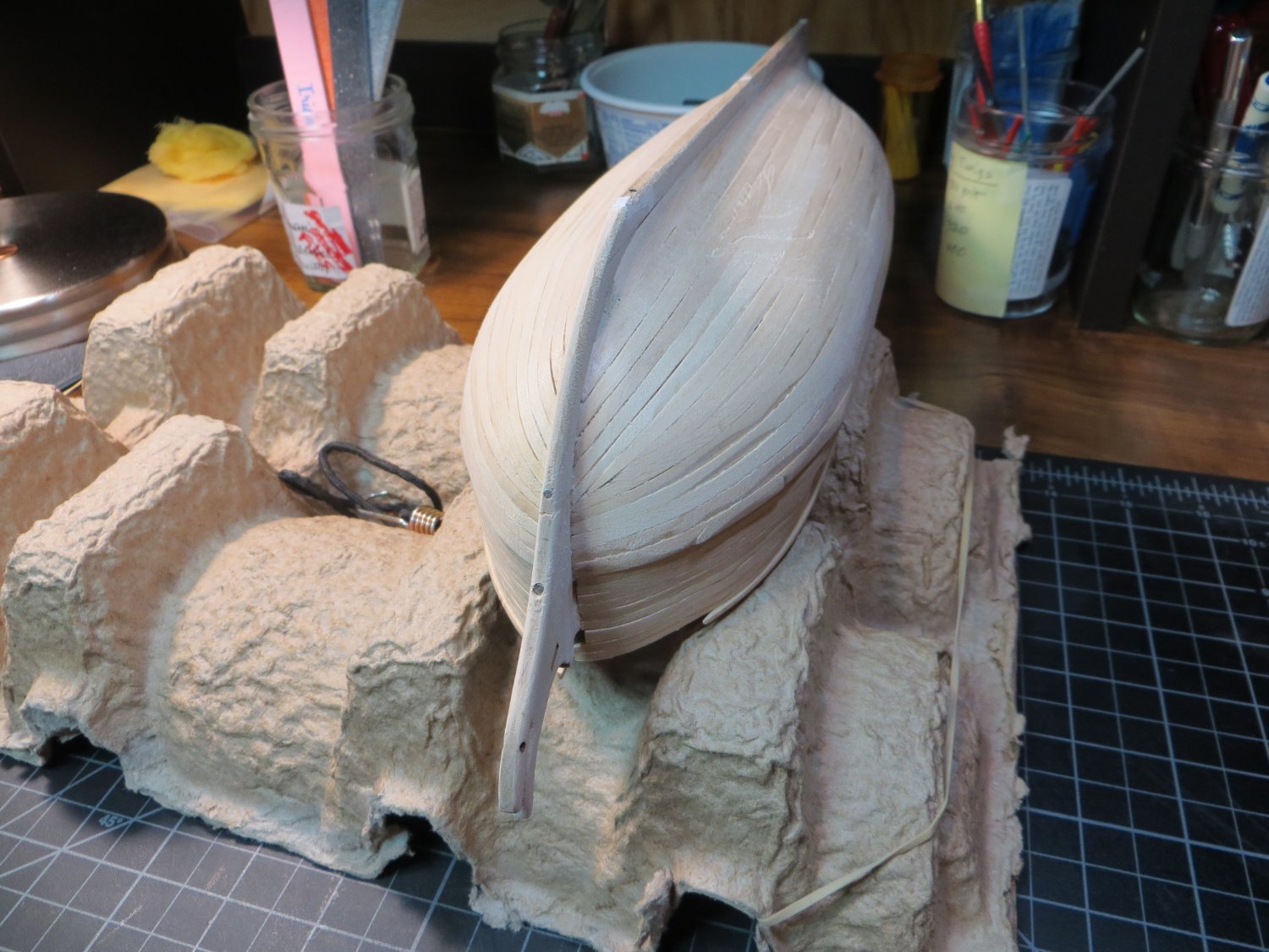
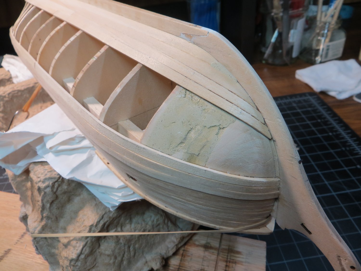
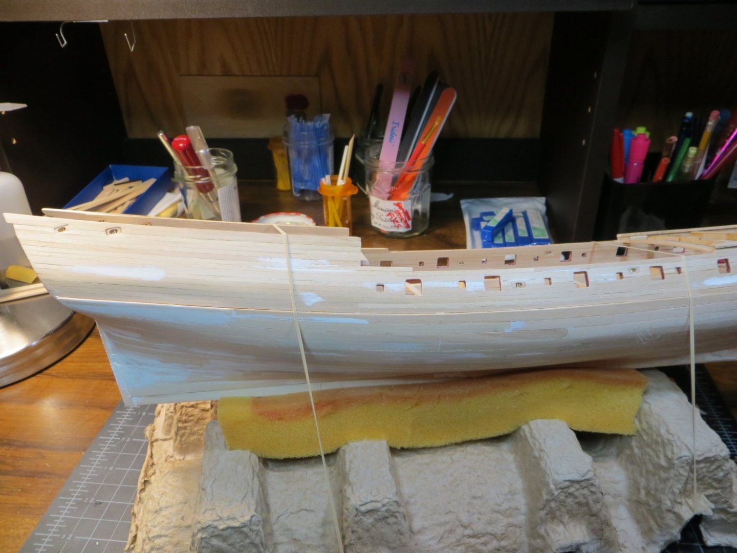
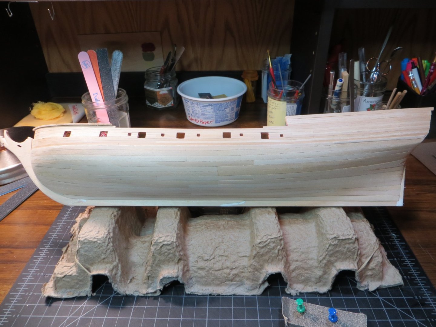
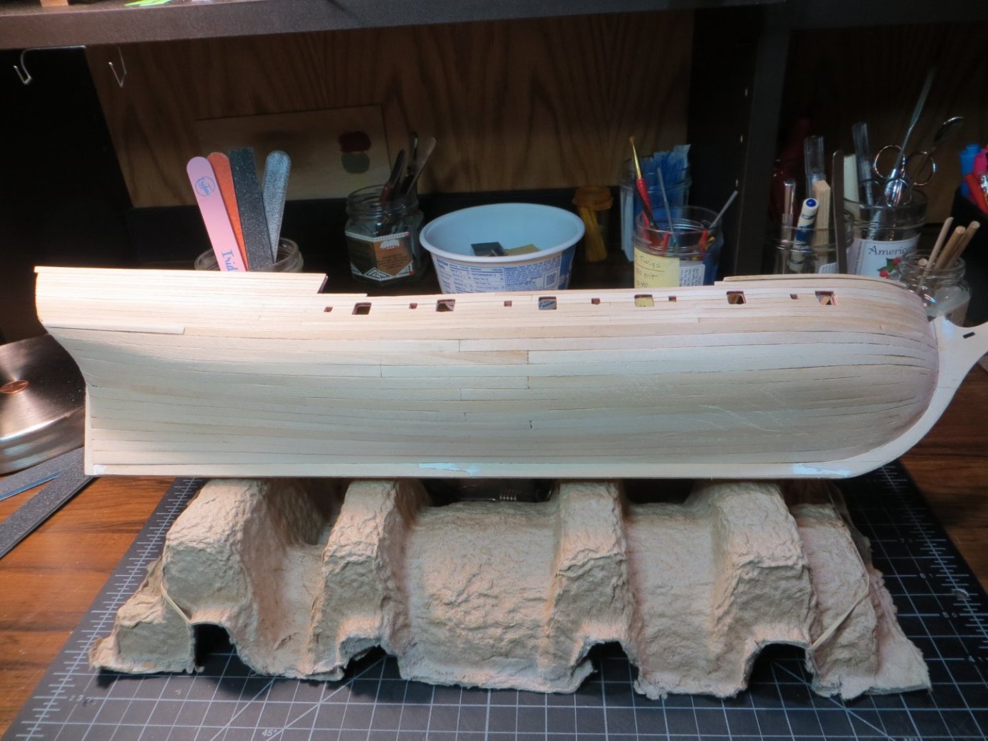
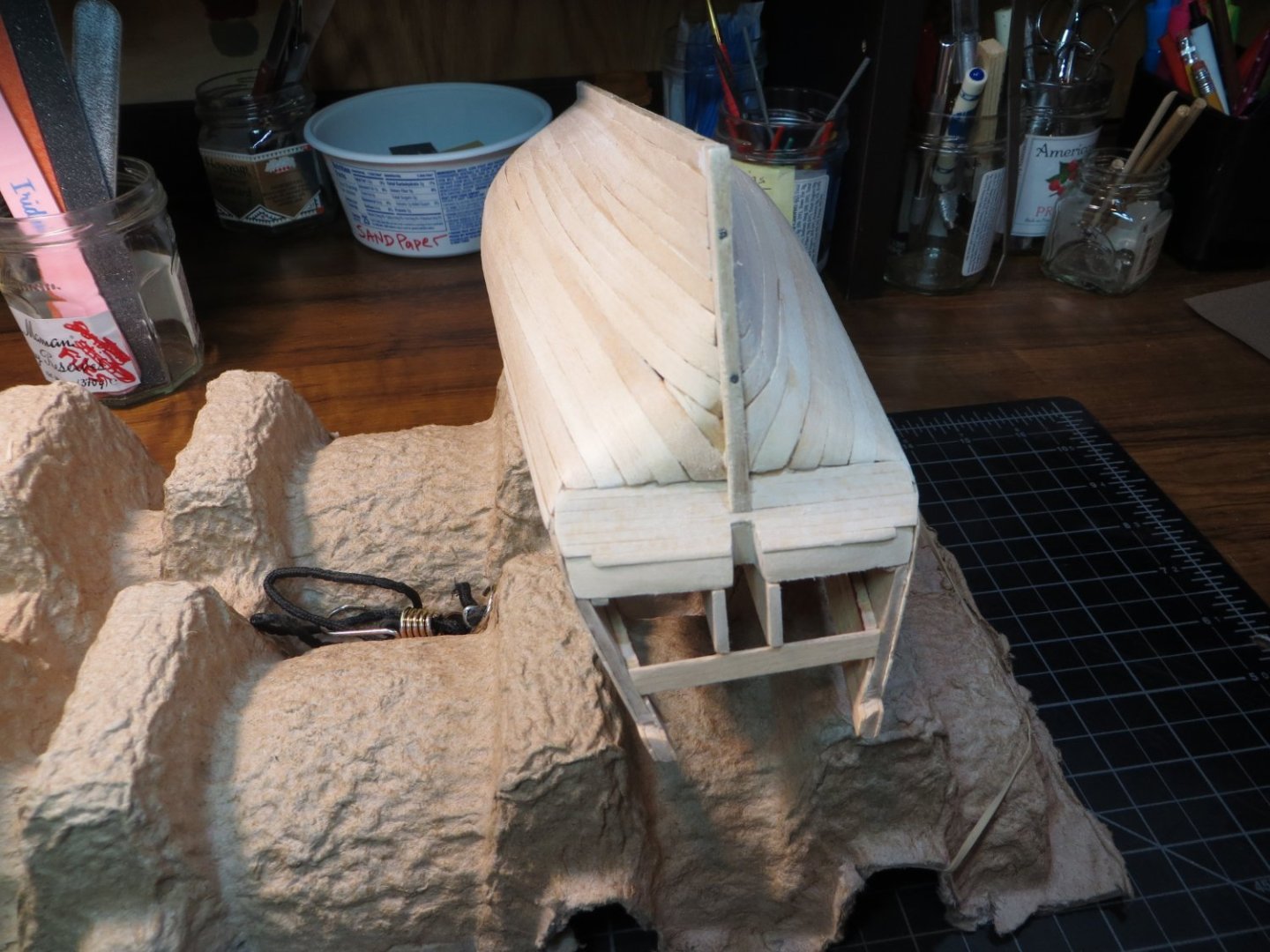
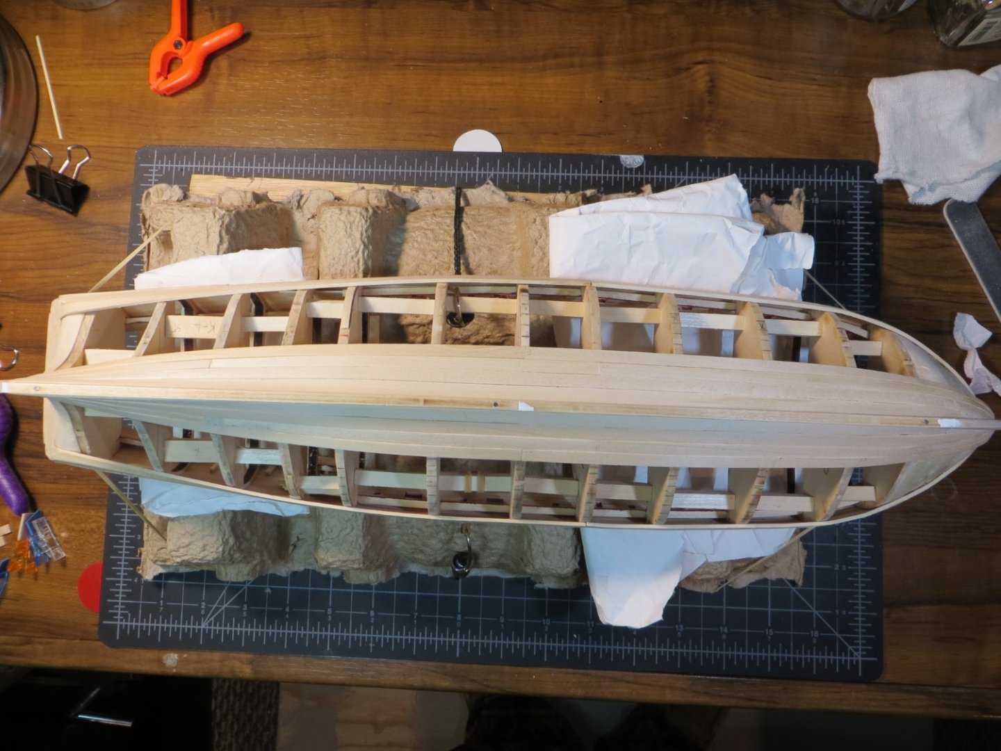
Hello Fellow Shipwrights, I've reached a major milestone on my build... planking on the lower hull has been completed. This step took me 100 hours and 72 calendar days. I found this hull to be difficult to plank! But, I learned a couple of things along the journey. I've already documented some of my difficulties! Here are a couple more lessons learned. Lesson #1. In my infinite wisdom (NOT!) I decided I didn't need to use battens to separate the hull into 3 sections, as per the instructions. In retrospect, I think that battens would have helped me avoid the issue I had with laying the planks in straighter lines and getting the same number of planks on both the port and starboard sides. I ended up with not enough space for the plank width at the bow and too much space at the stern. I solved this by custom carving and installing a jigsaw shaped piece to fill the leftover space on each side. And then inserting some narrow pointed planks at the bow, to have enough strakes to cover the stern. I think when the hull is painted and finished it will look fine. But, I took a shortcut that I will avoid on my next build. Someday I would love to build a ship without using paint. Just natural wood and varnish! Lesson #2. I think I should not have installed the extra filler block between bulkheads A & B. Or, at least they were not shaped properly. This caused me problems getting an even flow around that curve at the bow. I ended up with some "stairsteps" going on with my planking at the bow, because I could not get the planks to touch the entire surface of the block. That and I also had some severe edge bending due to the lack of a straight line caused by issue #1. This made it difficult to get the plank to lay flat against the hull on the "shorter" side (the edge facing the keel). At this point I've done some initial sanding to clean up the rough spots. I still need to do some filling and more sanding. I like to use Tamiya white putty to fill holes and smooth out the hull surface. It give a smoother surface than wood putty. After that, I need to repair damage I caused to two deck supports and the port side of the focsl covering board. Totally crushed that!! Here are some pics of the completed planking. Far from perfect, but I think I can work with this!

-
Dave, Damage is the reason! I just finished planking. Now I have to rebuild several deck supports plus the focsl railing. Not to mention breaking the stem off!! Lots of pushing and pressing against the hull in an upside down position. You'll be glad you did it first by the time you're done!
-
You are absolutely correct! I just broke another deck beam yesterday! I tell myself to be more careful, but you don't even realize you are putting pressure on a sensitive spot when the ship is upside down for planking. I even reinforced my beams early on. Oh well, I'm getting good at repairing the damage I cause!
-
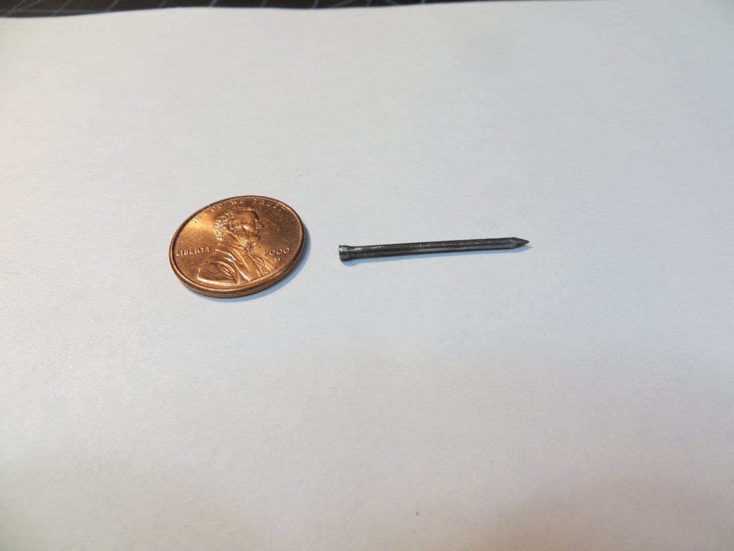
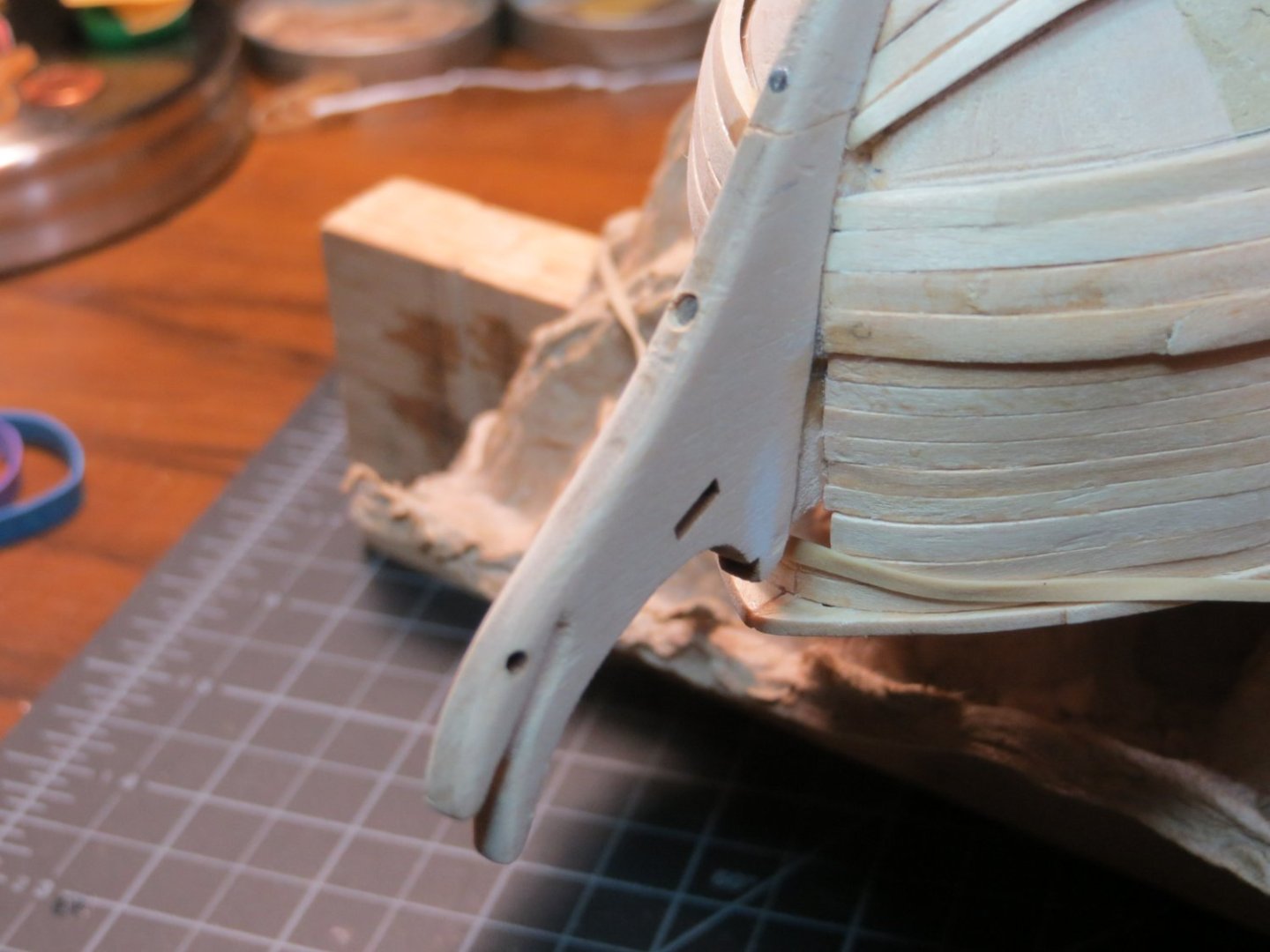
Hi All, So, I've managed to put Humpty back together again! I could not find a suitable sized dowel to use for the repair. I ended up doing as Richard suggested. I used a long thin finishing nail (less than 1/16 (7/128) x 1 inch long). I put the stem piece on the drill press and drilled out a hole that was a snug fit for the nail. Due to the width and shape of the stem, I felt I could only safely put no more than one nail through it. I positioned the piece and started driving the nail a very short way into the keel just to start a hole there. Removed the stem piece and applied a coating of Weldbond on both sides. Then I repositioned the stem and drove the nail all the way into the keel. I had widened the hole slightly at the top so I could countersink the nail head. I did not cut off the nail head so it would hold securely without adding any glue into the hole. Below are a couple of pics. I still need to do some filling and sanding, but I think it turned out pretty well. It seems very secure. I just have to be much more careful not to press against the side of the stem. Just 4 more strakes left to finish the hull planking! Time to get back to work! Below you can see the countersunk nail head in the repaired part. Above the repaired section you can see one of the original nails I used. This held secure when I broke it! Guess I should have used 2 from the start? Answering Woodshipguy...I did do a slight taper on the stem all the way to the keel. I mostly just removed the squared off edges. Thank You Gregory and Richard for your support! It was much appreciated in my time of crisis!!
-
Gregory, I was able to delete the post without any issues! Thanks Your approach on the repair sounds like a good plan. I am going to work on it. I'll let you know how it turns out. Thanks, Ed
-
Hi Gregory, Thanks for the tip. I'm always afraid to click on those delete buttons. I've read you can wipe out your entire log with one wrong click! My one concern about using dowels is lining up the dowel in part A with the hole in part B. The alignment on this piece will need to be very precise. Any suggestions on a technique for doing that would be appreciated. Thank You! Ed
-
Well boys, I just had a major problem!! I snapped the stem off the bow while trying to bend a plank in place. I'm not sure how to fix this. I'm afraid just gluing it back on will not provide enough reinforcement. I thought about inserting some dowels (small nails or pegs of wood) in the stem piece and trying to align them up with the keel. Does anyone have any suggestions? I hope I haven't wrecked my entire model!! Here's a picture of the damage. I've had some concerns about how thin that line of wood is along the rabbet. It's hard to be aware of that when you are pressing against the ship trying to hold stuff in place! I would appreciate any ideas on how to repair this. Thanks, Ed

-
Kenneth, your Rattlesnake is looking awesome. Your rigging looks very neat & tidy. Looks like you are getting close to completion! Did you stain the masts at all or is that just the natural color of the wood?
- 152 replies
-
- 1
-

-
- rattlesnake
- Model Shipways
- (and 1 more)
-
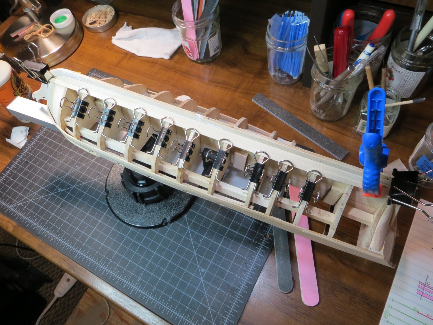
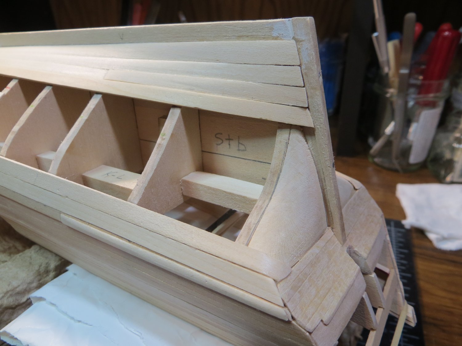
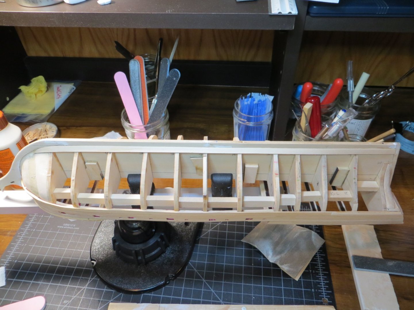
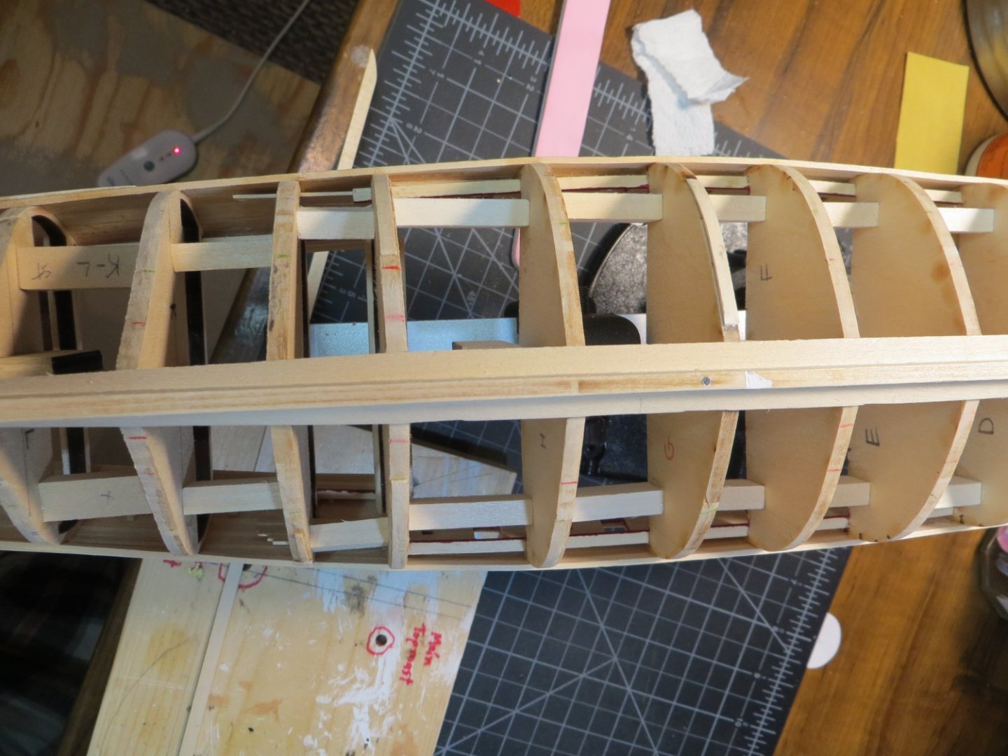
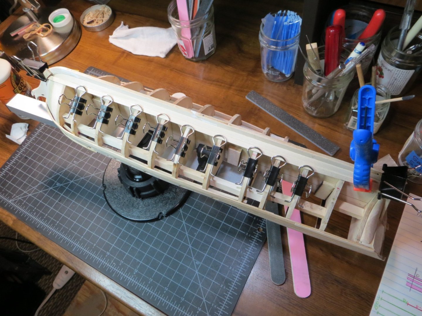
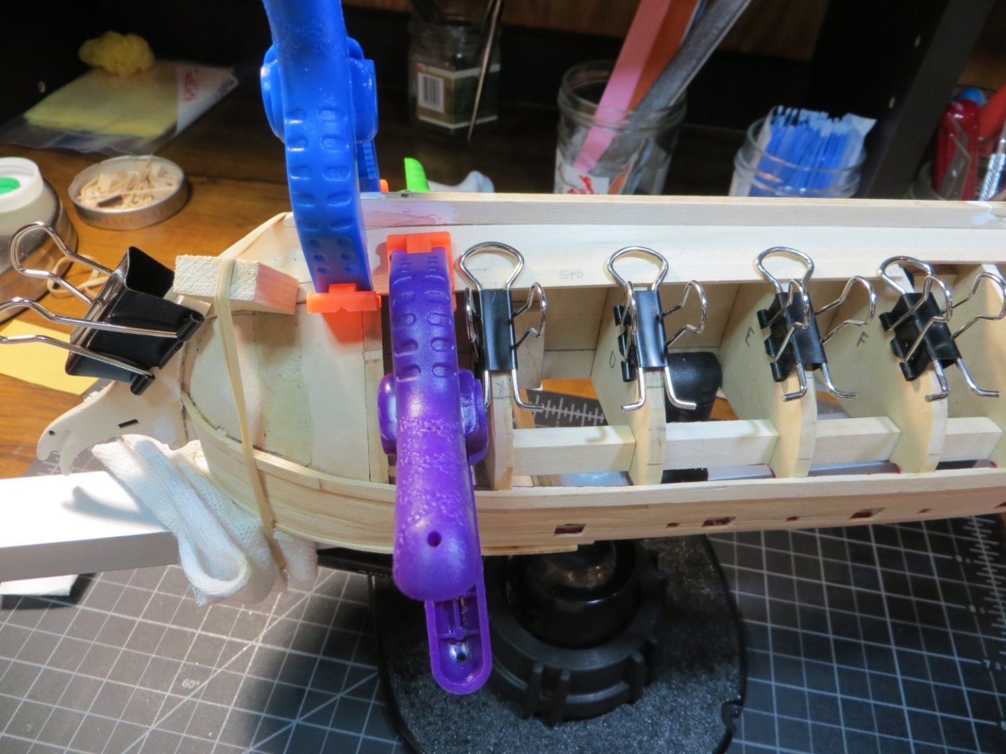
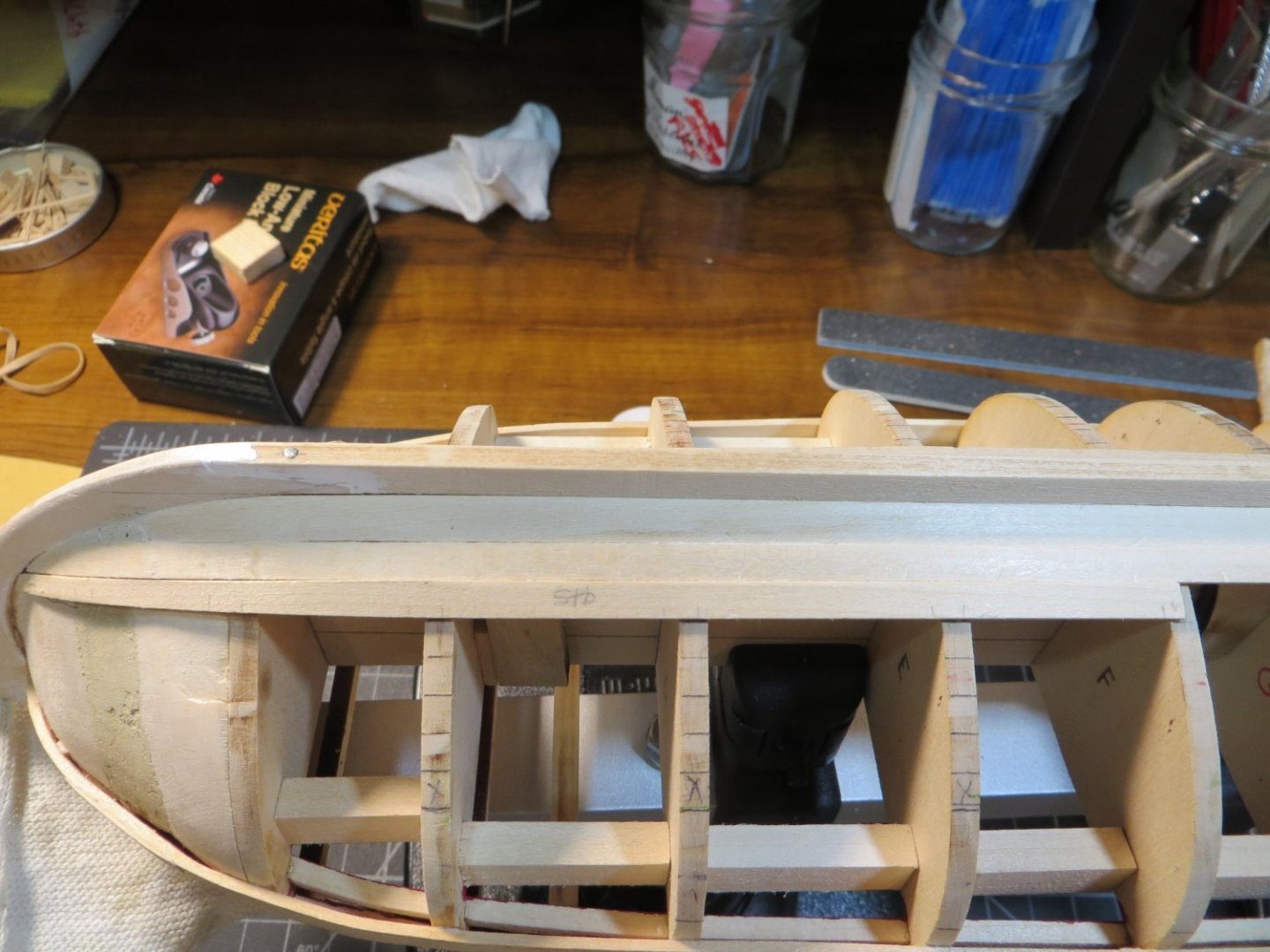
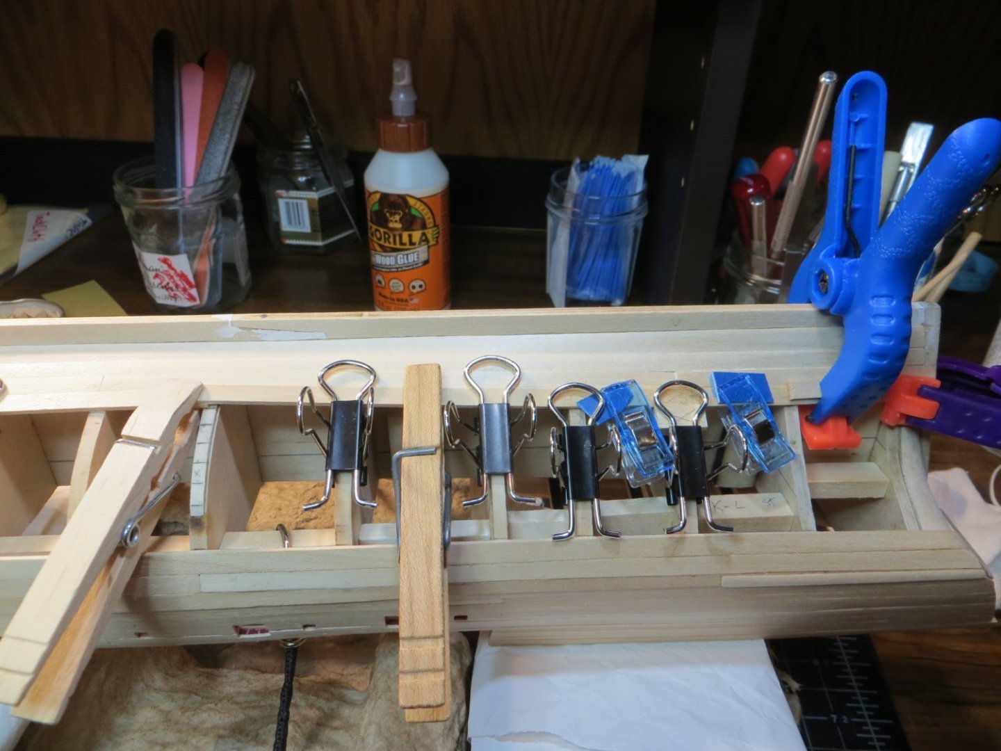
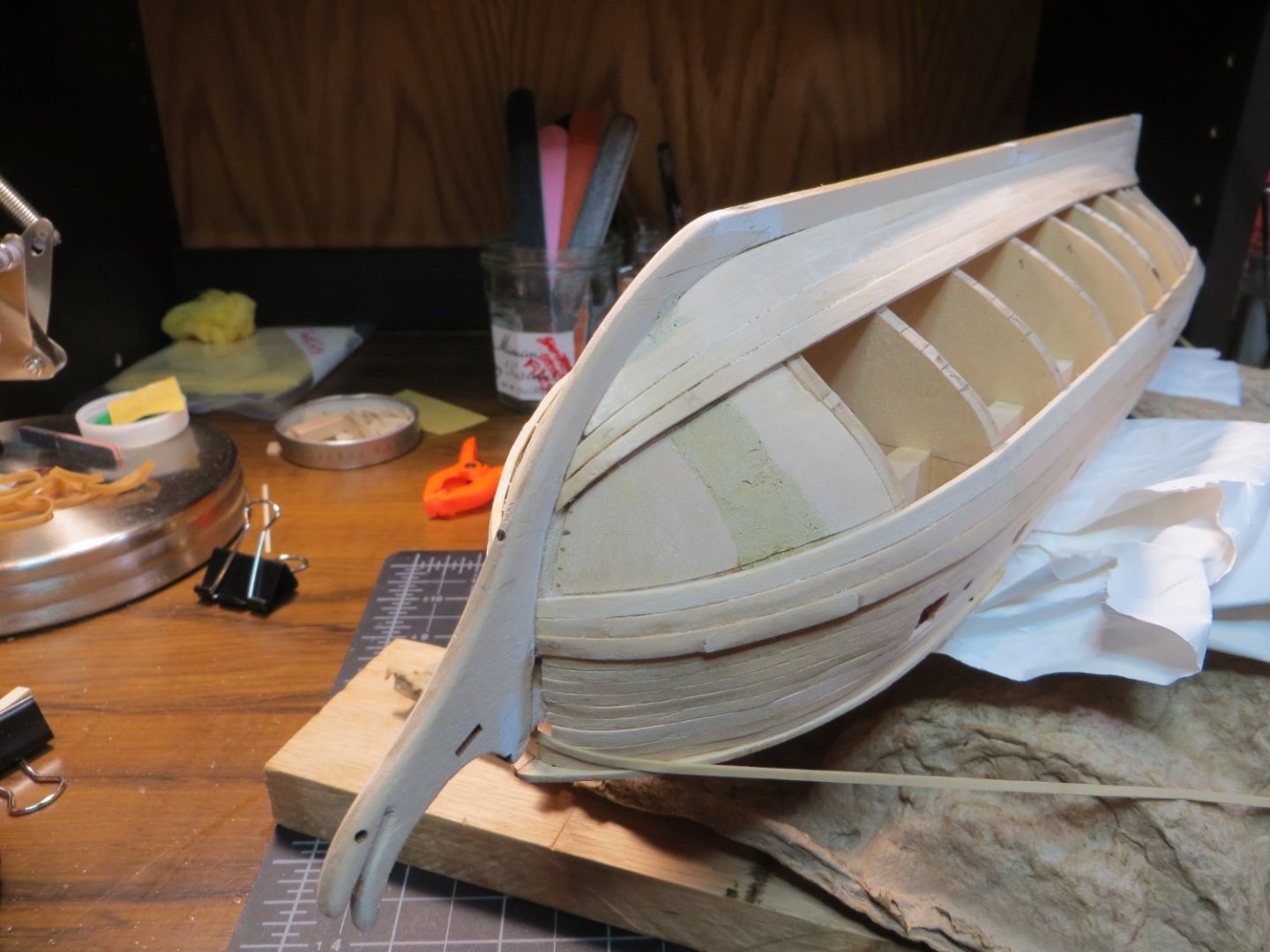
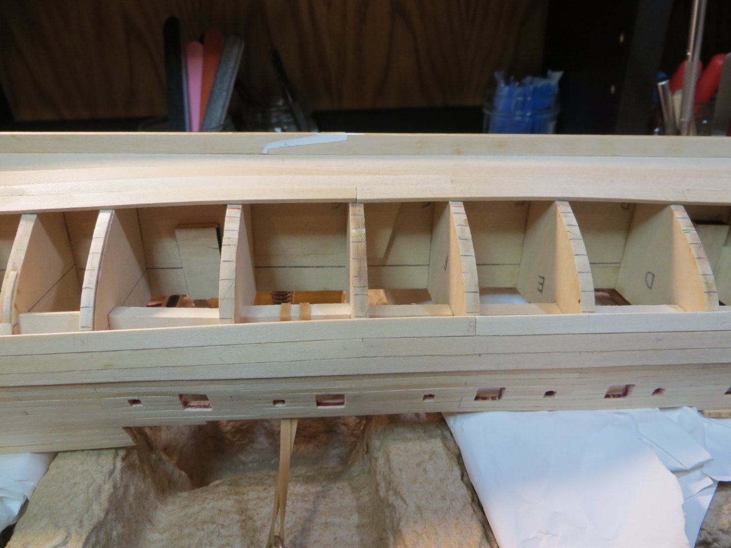
Stage C Lower Hull – Planking Hull Planking & Painting Step 25: Planking the Lower Hull As requested by Dave_E, I am posting my current progress. According to my master plan, I am starting on Stage C. Step 25 is Planking the Lower Hull. I spent a lot of time struggling to wrap my brain around how this step is supposed to go! I studied the pictures posted on every Rattlesnake build log to see how the planks are supposed to lay over the bulkhead frames and especially the bow and stern blocks. I watched You Tube videos on planking. But I have to visualize things on my model. I wasn’t getting the visual I needed from looking at the build log pictures. The videos, were helpful with techniques. I found some useful info from Ken Bascom’s tutorials. My plan was to start with the Garboard Strake. Then move ‘down’ the hull installing Belt C. Then move to Belt A. Lastly, fill the middle space with Belt B. I planned on using 3 planks per strake on each side of the hull. I still wasn’t comfortable, but decided to just start working and see what happens! I decided not to install any battens to start out. Garboard Strakes – I used a 1/16 x ¼” wood strip. This Garboard is not supposed to be tapered or cut. Run it straight along the keel. Only sand it to match the shape at the bow without any upward turn. This installed without any problems. Below: Garboard strake on starboard side Looking down on both Garboard planks Plank 1 (next to garboard) – Like the garboard, this plank is not tapered. Run it straight across on top of the garboard and shape at the bow without turning upward. Use the standard stripwood, 1/16” x 3/16” (part #3622). I sanded the lower edge to get a flush fit with the garboard. No butt joints were used. Below: Plank #1 being added A Pause and New Plan! At this point I took a pause. I needed to figure out how I was going to proceed. From now on the plan was to divide each strake into 3 planks per side. I also needed to figure out how I was going to determine the amount of tapering to do on the rest of the planks. I measured the distance between Plank #1 and the Wale at each bulkhead, plus the bow and stern. I needed to figure out how many full width planks will be needed at BHD G, the widest point. I did not trust that the measurements off the plans would match my model! I had to visualize it on my ship! So, I cut short pieces of planking that would cover 3 bulkheads. Using some rubber bands around the hull, I laid down planks in the empty space between plank #1 and the Wale along either side of BHD G. I came up with 11 full width planks required. I made a spreadsheet and determined the plank width required at each bulkhead, the bow & stern. This revealed that tapering is only required at the bow. Most of the planks will work fine at full width. And the stern might need an extra stealer, because it could be wider than 11 planks. I decided I did not need to use battens. I drew lines on each bulkhead using my test planks to show where each one fits. My new plan is to alternate between the top and bottom of the hull laying down planks. I will check my measurements as I go and adjust the amount of tapering to match the remaining gap. Plank 2 – On the next strake I used 3 planks per side. The bow now had to be tapered. I love the Veritas block plane. It makes tapering a snap. Unfortunately, I made 3 mistakes at this point. a. I did not realize it at the time, but I extended the tapered length for this plank at the bow to be longer on the starboard side versus the port. I only now realized that this messed up my calculations and will leave this side a strake less at the starboard bow! More on the solution to this problem later. b. The butt joint at bhd K had all the edge bending tension and caused a bulge. I thought about how to fix this for a while and considered inserting a stealer. This seemed too scarry to attempt! So before installing strake #3, I drew a straight line connecting the smooth parts at the bottom of the strake on either side of the bulge. I cut the bulge out with an Exacto knife. This also reduced the amount of edge bending occurring at the stern for future strakes. I also decided to use only 2 planks per strake from now on. It’s too difficult to hold the plank flat and bend at a joint. c. But the worst problem I had was this...I was pushing on the plank to force it to stay in position and I snapped the deck side of the keel where the two keel clamps were holding the ship upside down!! I also crushed a couple of the deck supports in the process. I thought I was going to cry! I managed to glue Humpty back together again. But, I’m afraid to attach the keel clamp again for planking. I went back to my old school pre keel clamp. I cut up a wine bottle cardboard shipping insert to fit the Rattlesnake's shape and strapped it down. It’s actually working fine. Below: Installing Strake #2 Strake #12 & 11 – Next, I decided to jump “down” and work on the strake just below the wale. I wanted to see how the planks will run into the transom. OMG, the bend & twist around the stern filler block into the transom is a bear! I’m developing whole new techniques to soak and bend wood at a 90-degree angle with a curling iron!! Every plank must be cut, soaked, bent, soaked and bent some more, wet fit and clamped to the hull until dry. I messed up the first one, but I’ve made some good plank bends since. It takes me about 3 days to complete each strake (port & starboard). That brings you up to date. I’ve completed the Garboard and the 3 strakes next to it and 2 strakes under the wale. I’ll need to do some filling and sanding when done, but I hope you guys think it looks pretty good so far. Here are the last pictures taken today. Below: Dry-fitting strake #3 Current progress as of today: FYI, to solve the issue with the starboard side with plank #2 I decided to increase the tapering at the bow end to fit the missing plank. The planks from bhd D to the stern should not be affected. Hopefully, once everything is sanded and painted no one will know the difference. Thanks, Ed


-
Hi Dave, Just got back from a couple of weeks vacation and am catching up on your build log. I also purchased the 6 pounder cannons and the recommended carriages from Syren. They are bit taller then the Model Shipways, but not off by an large scale. I was able to adjust the height of the frames to compensate for the difference. I agree, the difference in the quality of the cannons is worth the extra effort to make them work. I only built one cannon for test fitting the frames, so far. I intend to deepen the grove the extensions on the sides of the cannons sit into on the carriages to help make them fit better too. I don't know if it's too late for you to try that. Good to see you are back in the shipyard! Ed
-
Hi Guys, I've got one more post to complete the steps on the upper deck, at least for now. I told you I had an idea how to get the laser-cut Focsl Covering Board to fit. Well I'm happy to report this worked! I soaked the 2 pieces for the covering board for a good 10 or 15 minutes. While that was preping, I turned the ship upside down on a piece of thin cardboard and traced the outline of the bow/focsl on the cardboard. I placed the cardboard on a piece of cork board. When the covering boards were pliable, I used pushpins to hold them in place inside of the outline I traced. I let this dry overnight. This afternoon I was able to glue them in place on top of the focsl with only minimal adjusting! I am very pleased with the end result! I still have a few steps left. Sanding and wood fill, install the railings, prime and paint the areas that will be red. I'm going to wait until the lower hull is planked before doing these steps. I don't want to damage anything while working on the ship upside down. I expect progress will slow down a bit while I'm planking. Here are a couple of pics of the focsl covering board. Thanks, Ed