HOLIDAY DONATION DRIVE - SUPPORT MSW - DO YOUR PART TO KEEP THIS GREAT FORUM GOING! (Only 36 donations so far out of 49,000 members - C'mon guys!)
×

Ed Ku20
-
Posts
230 -
Joined
-
Last visited
Content Type
Profiles
Forums
Gallery
Events
Everything posted by Ed Ku20
-
 Hi John, I've read through your build log a while back and took a lot of good information from it. I made notes from you and JPett about the inboard bulkhead fairing. I might not have picked up on that otherwise. Welcome to the party! Glad to have you aboard. Let me know when any other pearls of wisdom come to mind. I will be following your build as well. Looks like you are getting close to completing planking. Looks great! Thanks, Ed
 -
Thanks Dave! Hope you have a great time on your vacation. If you're on the Big island, watch out for molten lava flowing down the road!! Haven't had as much hobby time the past couple of weeks. Busy with family stuff this time of year. But, that's no problem...its not a hobby if you're in a hurry, right? Safe travels, Ed
-
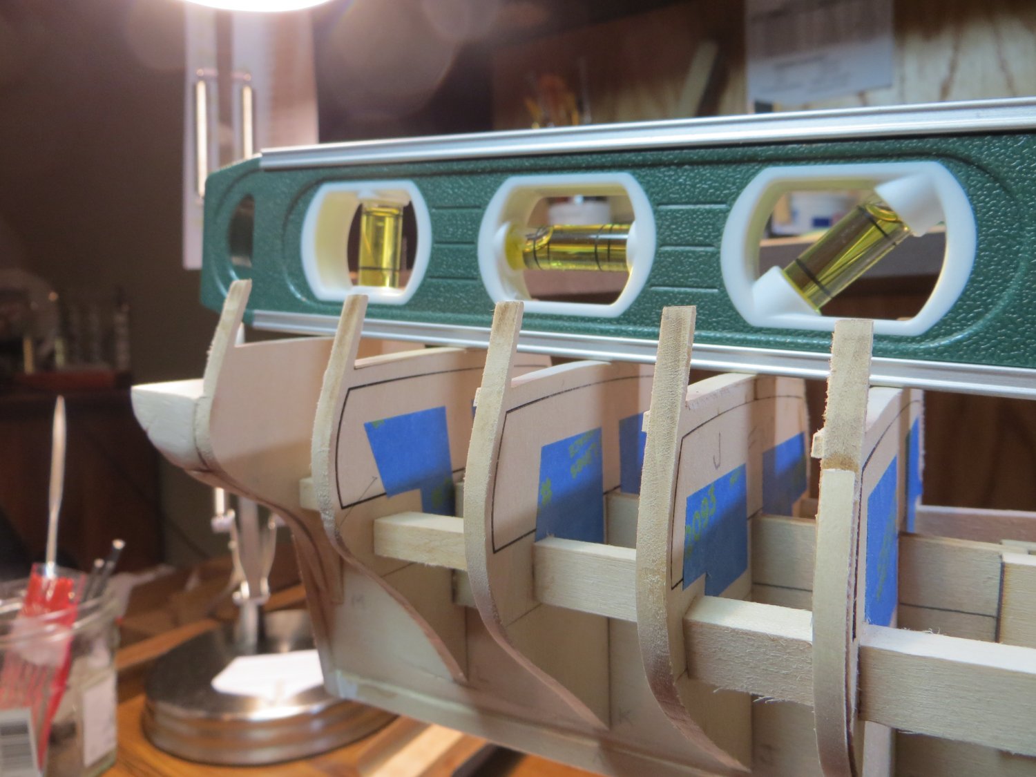
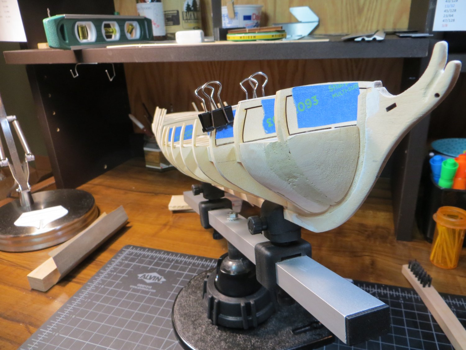
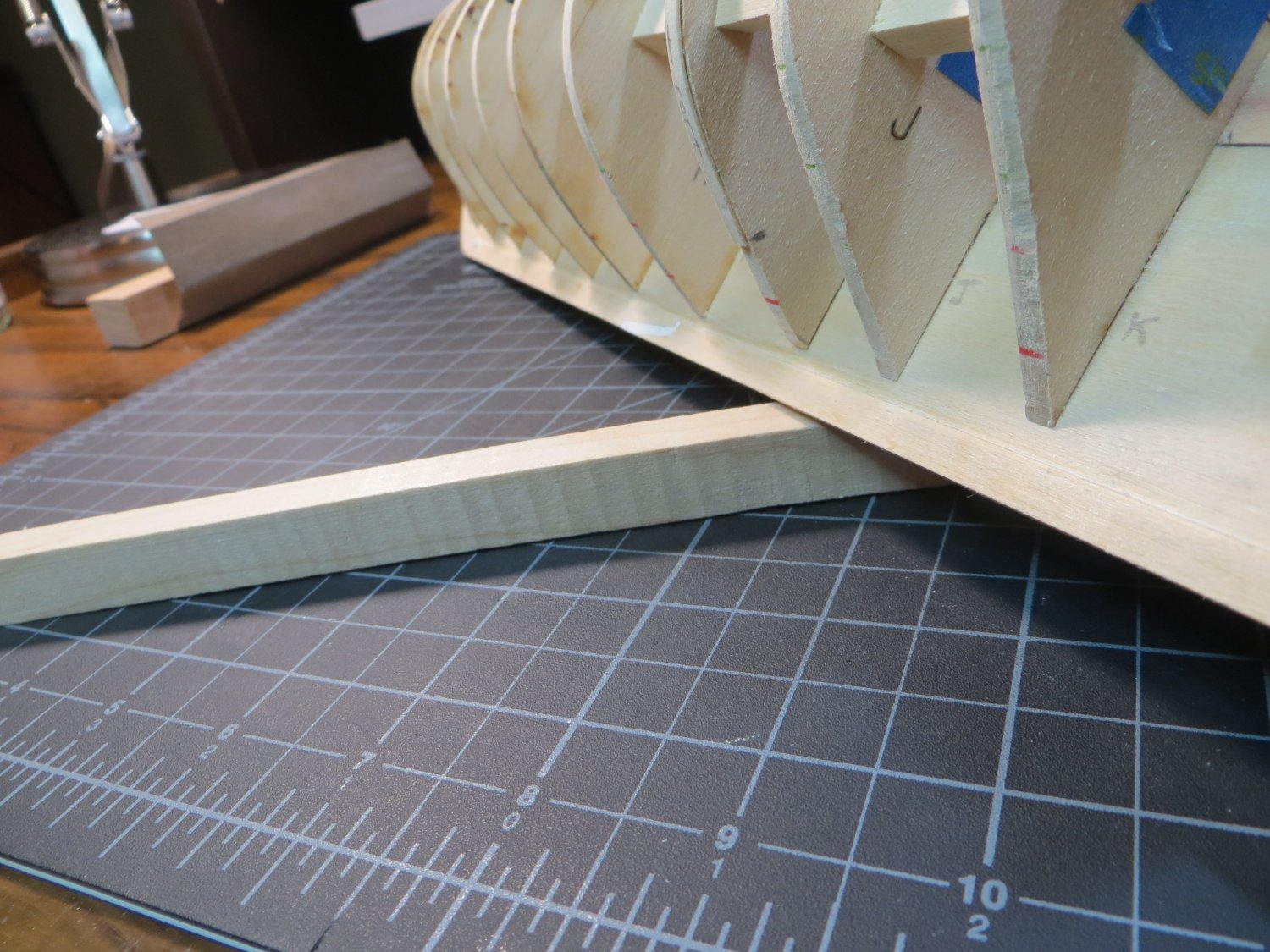
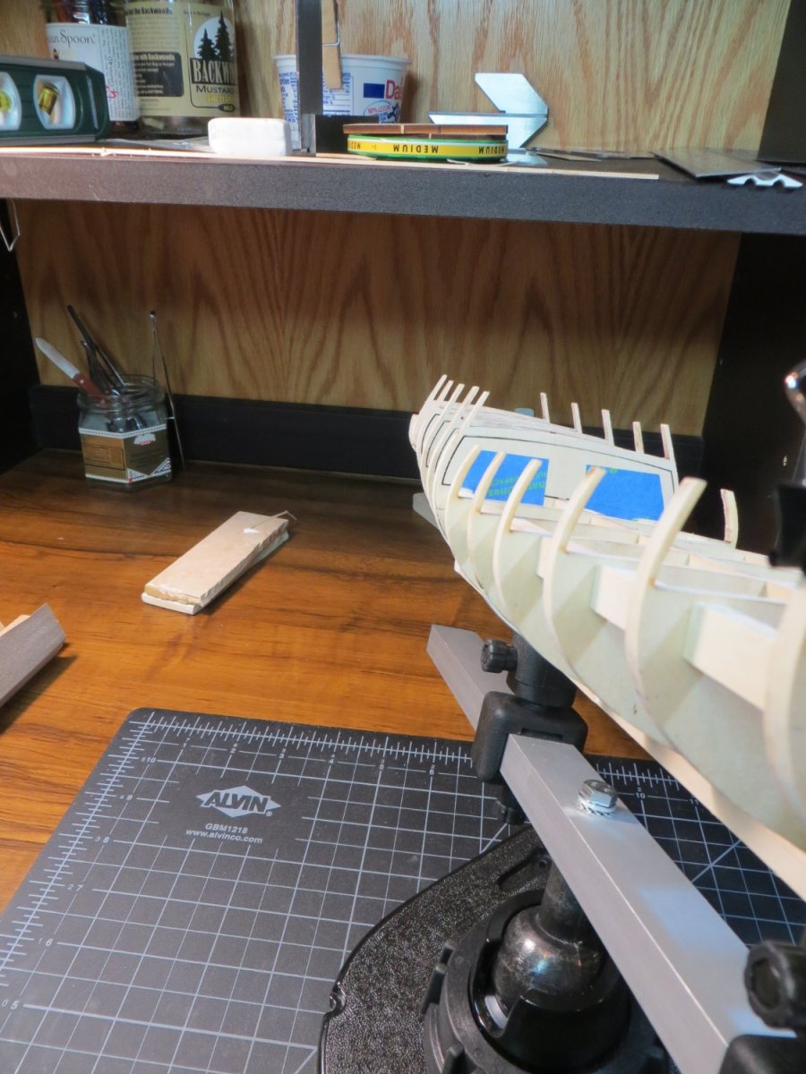
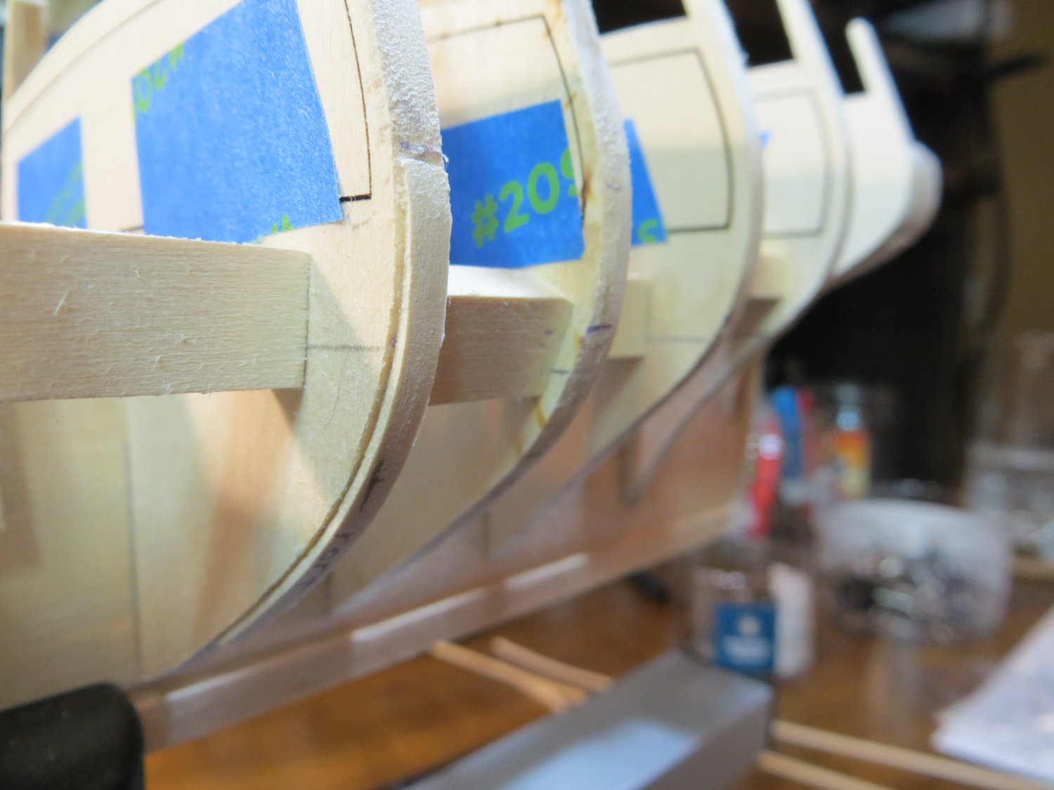
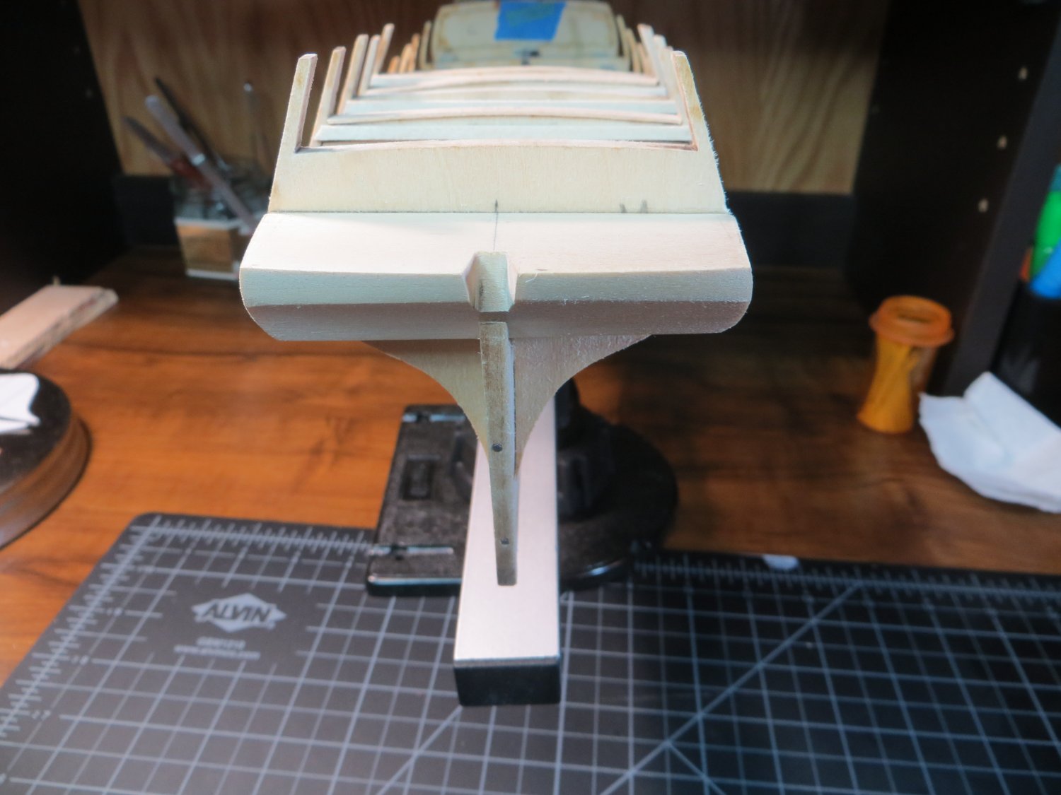
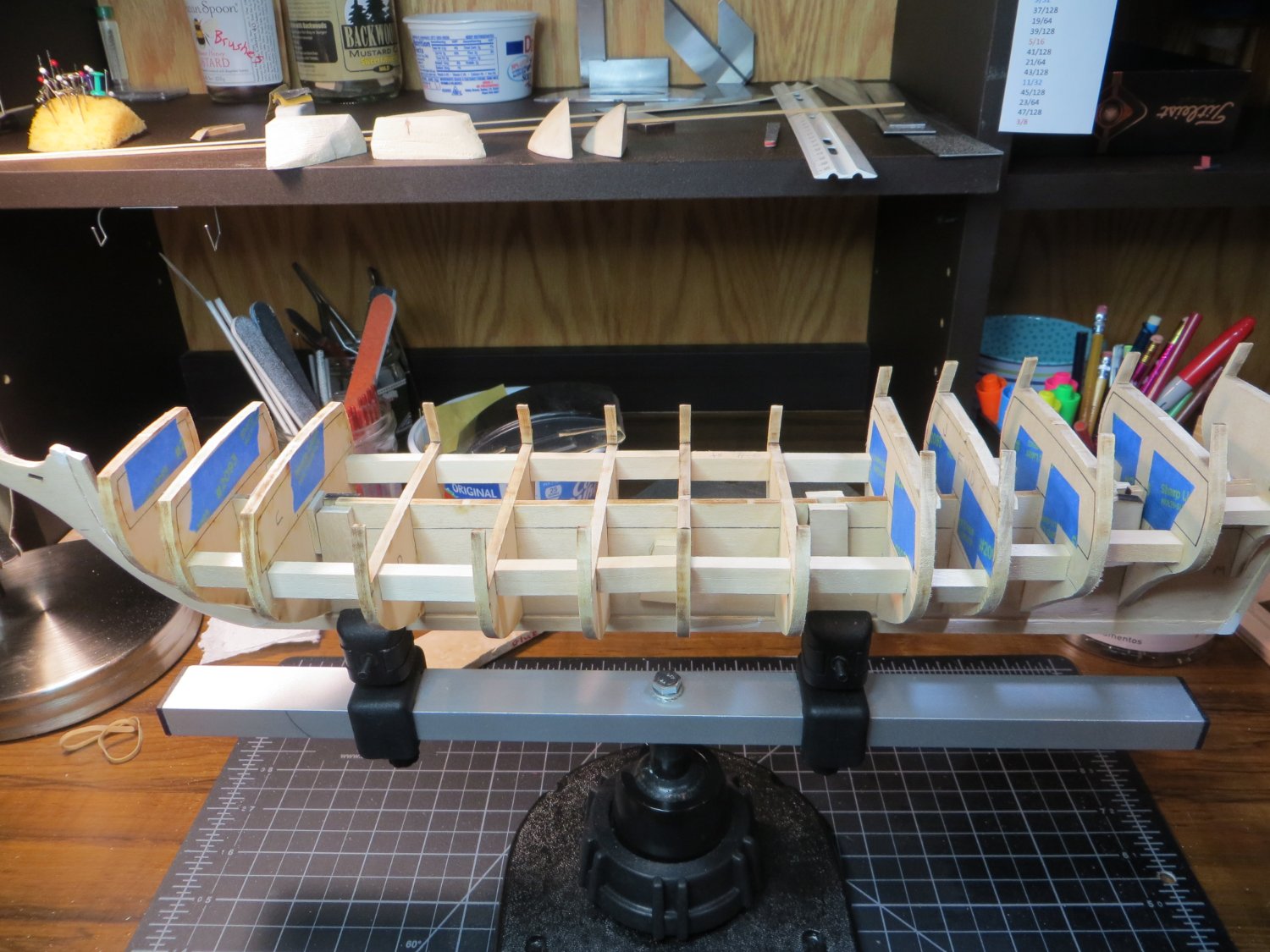
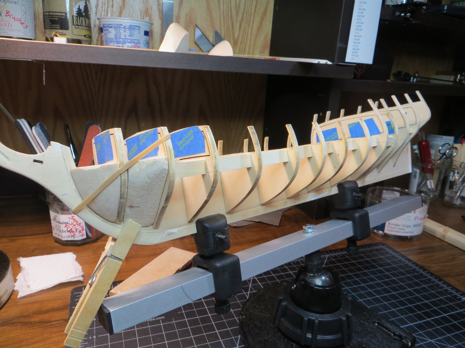
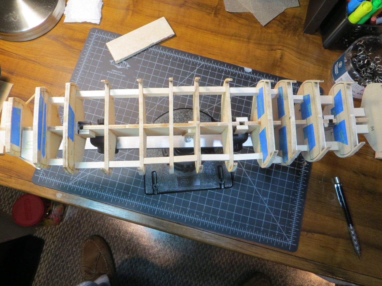
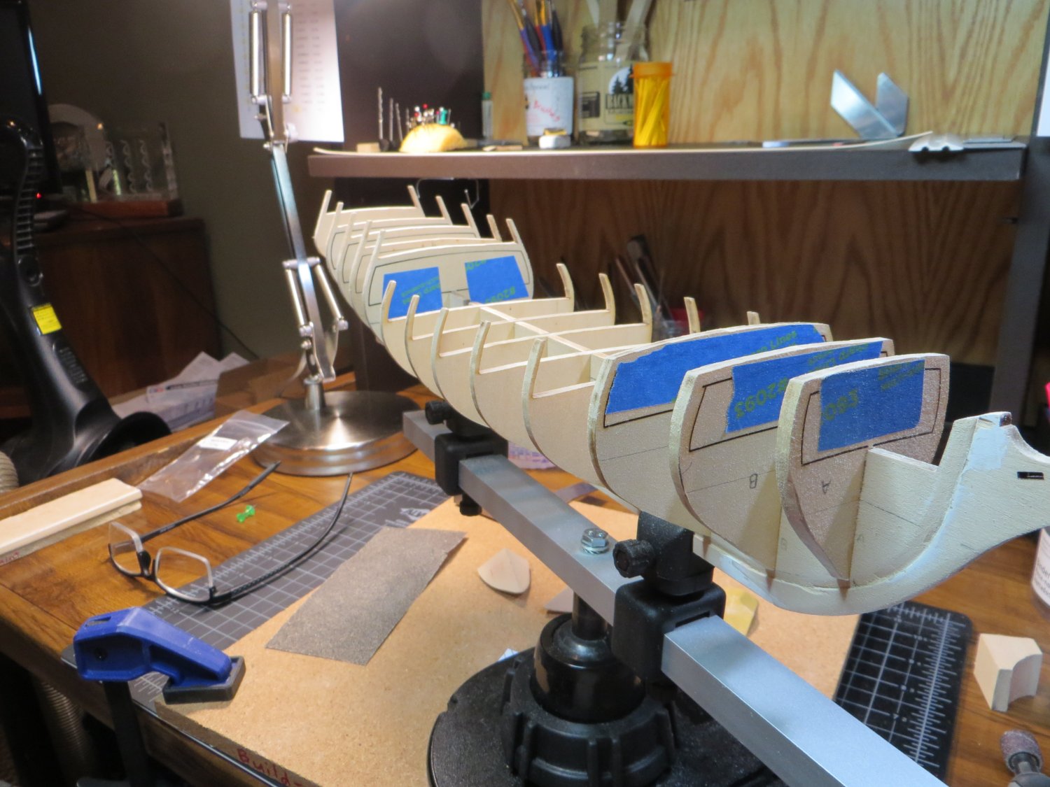
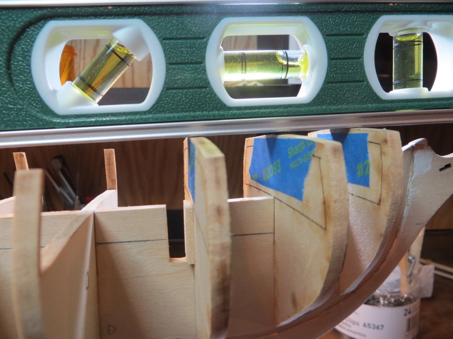
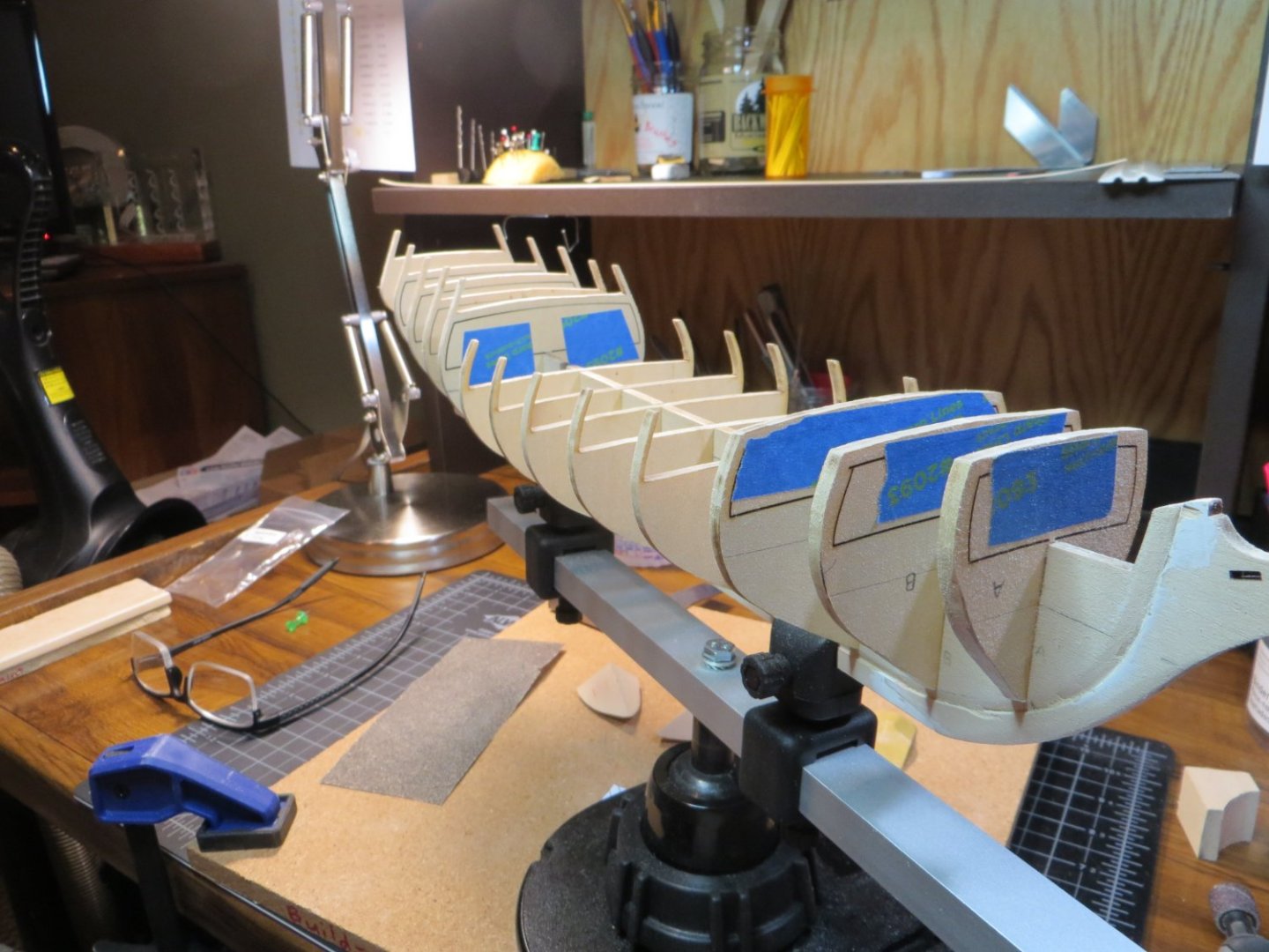
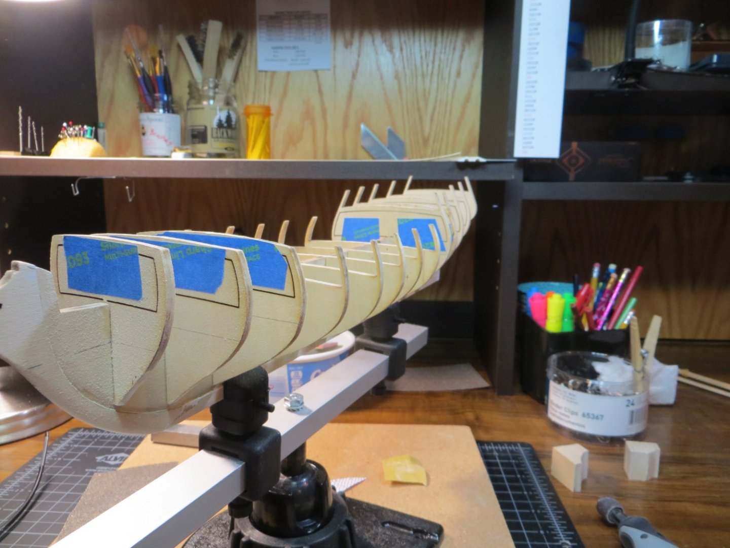
Step 11: Fairing the Hull I completed Step 11 in my build procedure over the last couple of days. This concludes what I call Stage A: FRAMING the HULL. Step 11 consists of checking over the bulkheads and then fairing (sanding) the BHD edges to get a flat surface for the planks to be glued on. Here are the individual tasks I completed in this step. Step 11: Check every BHD and then Fair the hull a. Bearding Line – make sure it’s deep enough all the way around. Test fit planks including the Garboard strake b. Make sure BHD’s are at the right length and do not run past the bearding line c. Bow & Stern Blocks – sand and add wood filler as needed to get a smooth transition at both ends d. Attach test Battens to see where BHD’s need sanding or shimming e. Shim & sand the Quarterdeck and Forecastle deck so they are aligned under a straightedge f. Do a final sanding (FAIR the hull) by doing the BHD’s & filler blocks all together Here is what the Bearding Line looks like on both sides of the ship. I had to make the cut a little deeper at the keel in a several spots. The Bulkheads looked pretty good here with only a little sanding required I had added another filler block behind BHD A to help make the curve into the bow easier for planking. I put a bunch of wood filler in some gaps there. I sanded everything down. There are still a few holes, but I think there is enough surface that these will not be a problem. I marked the location of the A, B & C planking belts. I attached test battens to see where there were bumps or dips. The bulkheads mostly required shimming in a number of spots. These got sanded smooth along with the BHD’s at the bow & stern where they need to be angled. Example of a shim glued to one of the BHD’s and the faired frame P/S Finally, I added a lot of shims on the quarterdeck and the forecastle deck. I did not attempt to make the height at the tops of these bulkheads equal. I studied & measured the plans and it seems to me that there is a definite slope on both of these decks toward the midship (BHD G). I shimmed and sanded until my straight edge lay flat across all the BHD’s. I hope I haven’t screwed the whole model up, but I had to go with my gut on this one!! Quarterdeck after shimming and sanding. The center bubble on the level shows the slope toward midship. Please give me your comments or suggestions! I’m on to STAGE B: Upper Hull Planking and Deck Details


-
Hi Dave, good to hear you are doing well health wise. And also glad to see you back at it with your Bluenose. I like the jigs you made to cut the mast tenons and cheeks. Wish I'd thought of that when I was doing mine. Keep up the good work! Ed
- 389 replies
-
- 1
-

-
- bluenose
- model shipways
- (and 1 more)
-
Dave, are you using an air brush or regular paint brush? If air, make sure you buy paint made for an air brush. I've had trouble with paint flow otherwise. I did not like the ME paints I got for my Bluenose. I used Vallejo paints, either their Model Air or Model Color paint. Had good results with them. You can buy most of these singly on Amazon. I purchased Model Air "Off White" for the lower hull. I kind of like the "tallow" color look together with the yellow ochre and black above. So, I guess everyone has their own eye for color!!
-
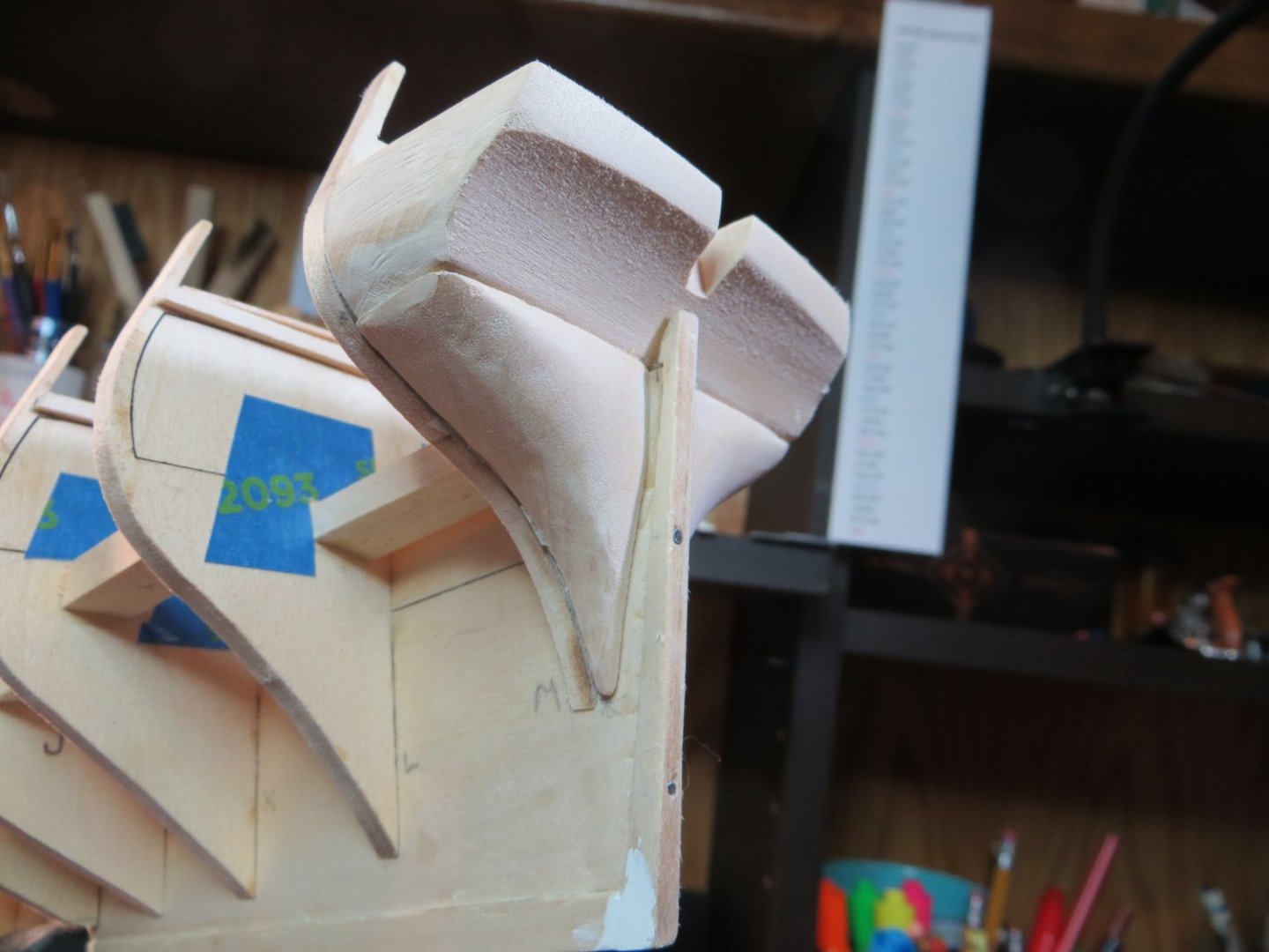
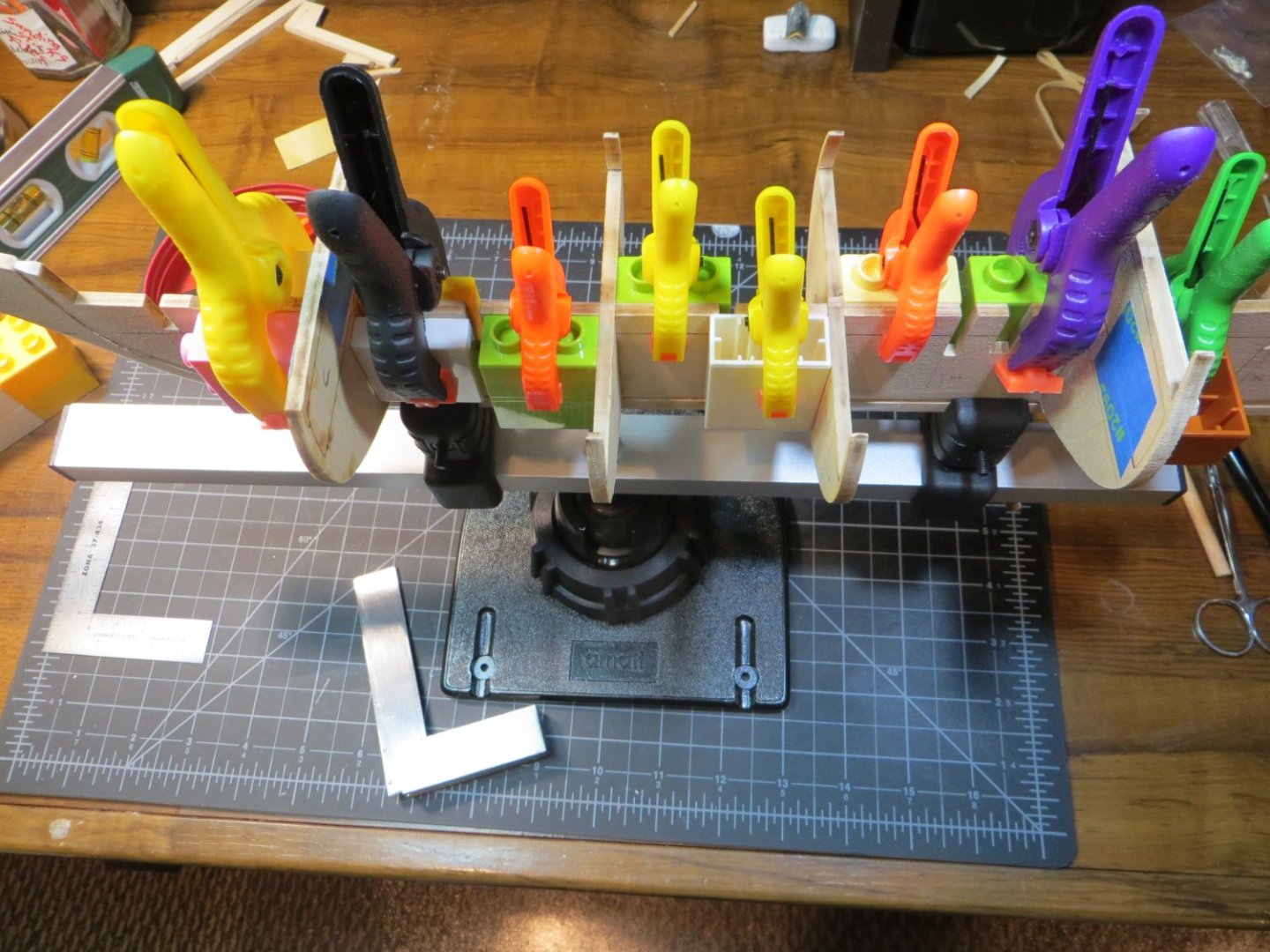
Hi Dave, I put the boys on a sandpaper diet this afternoon and took a couple of pics of the results. I tried to get a good angle so you can see the profile. Do they look any better? My double-faced tape isn't holding the starboard side too well. I took a lot more wood off, but not sure you can tell from these pics. Also, I identified the wrong build log earlier. The pictures I liked were by Dimitry Markov from Moscow. He had a really nice looking Ratt build going, but his last post was in April of 2021. He took some good pictures! Too bad he didn't continue.

-
Thanks for the feedback Dave! I thought they looked a little fat too, but don't want to take too much off either. You can't put it back! I was looking at the log by Divarty last night. He has a lot of nice pictures of the planked stern. As long as he's done it well. It looks good to me. Enjoy your time in Hawaii. I'm jealous!
-
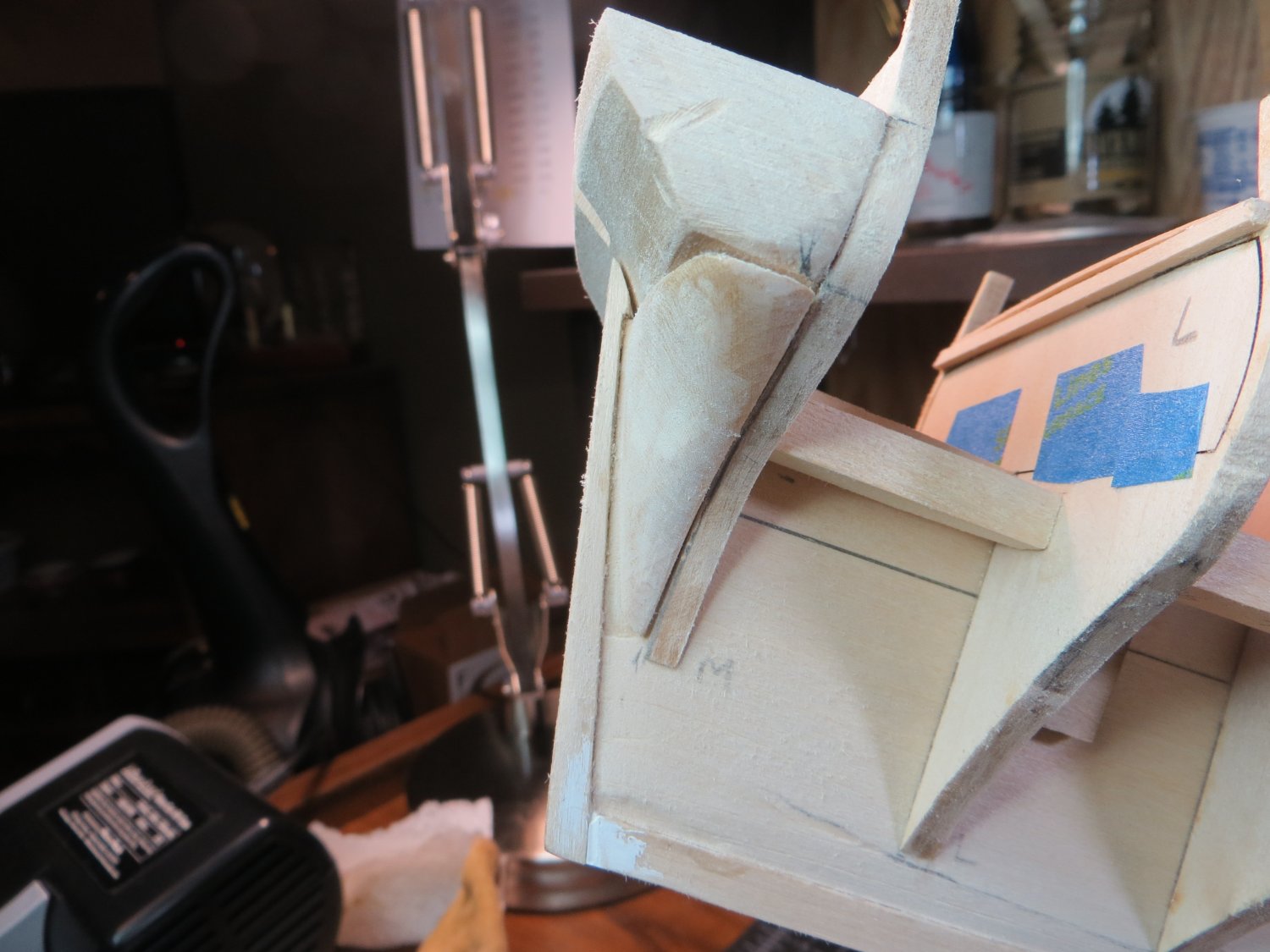
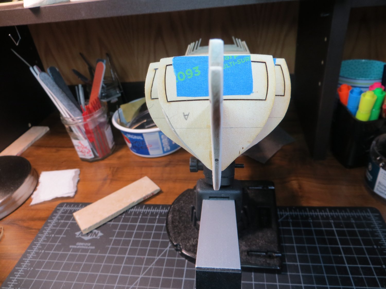
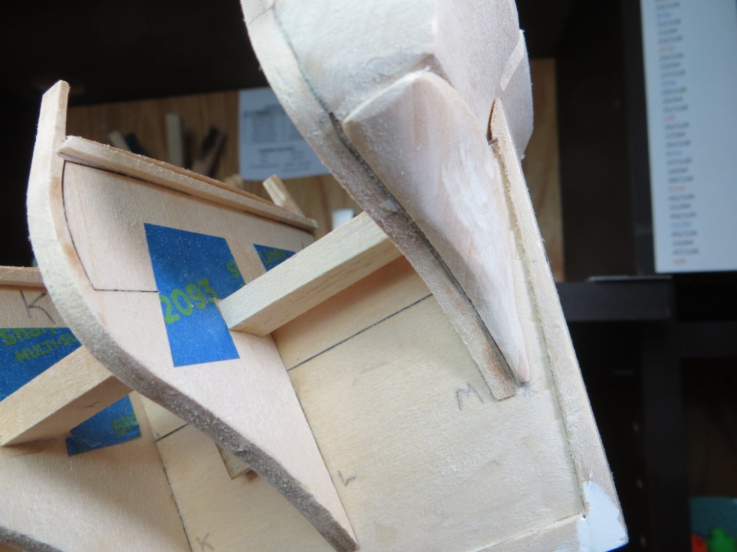
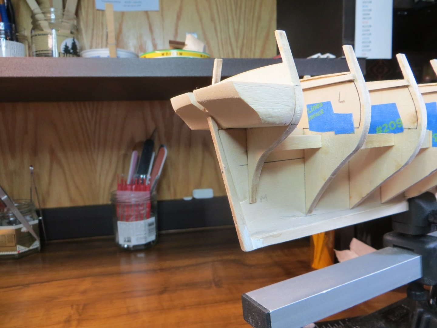
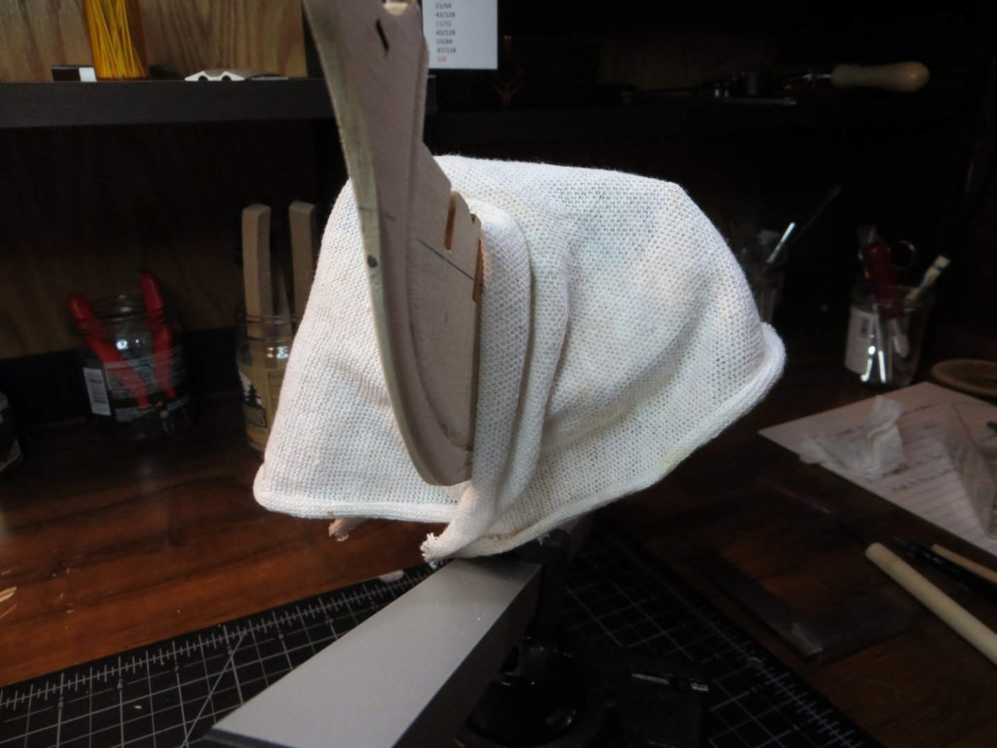
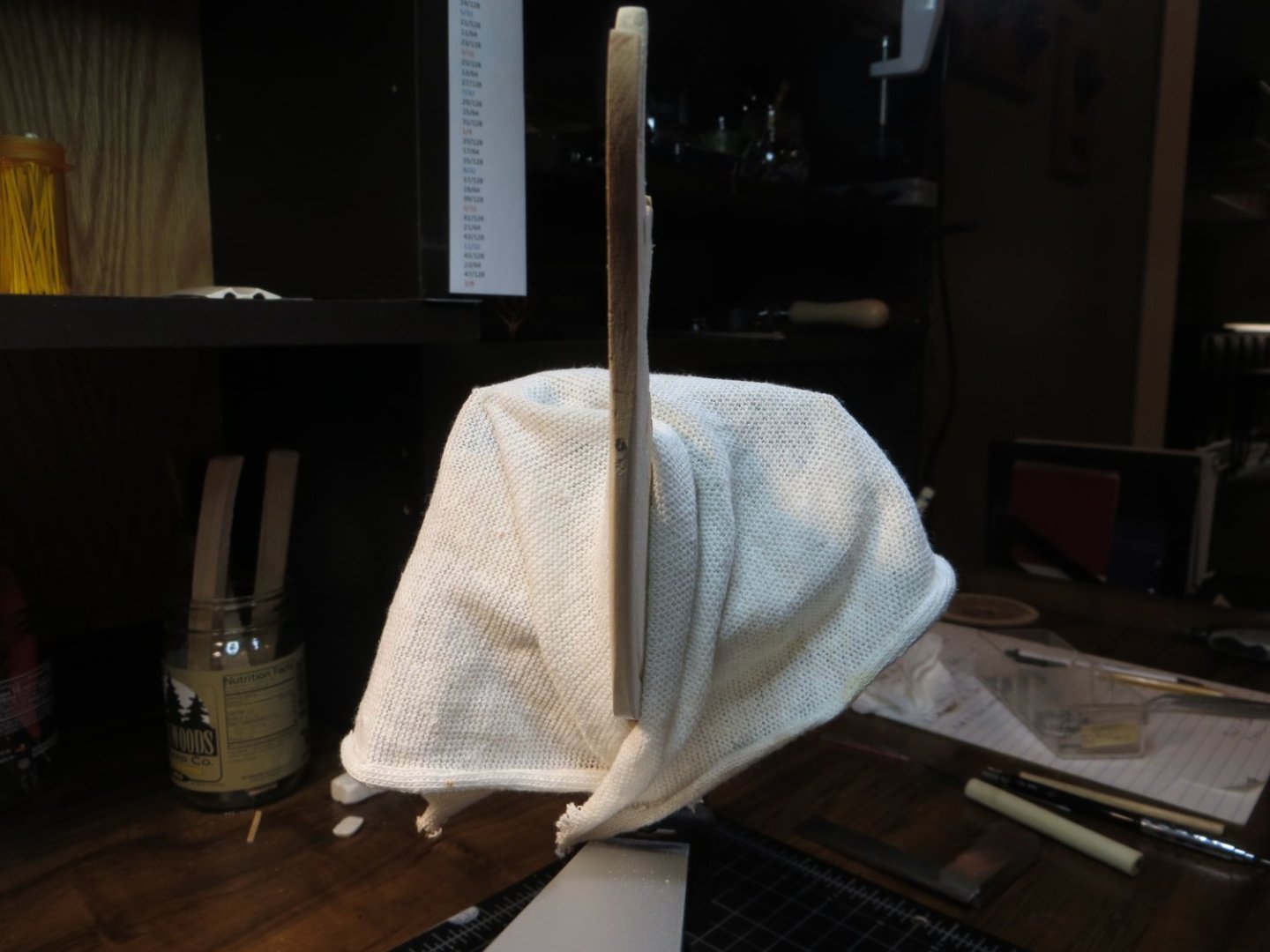
Step 10: Carving the Stern Filler Blocks I found that carving these filler blocks was hard to do!! I traced the initial shape from cutouts off the plans and then used a coping saw/mini-vise to cut off a few chunks of the excess wood. Thank goodness I bought a Dremel! I raised clouds of sawdust with the 60 grit sanding drum getting these pieces into shape. The pictures below show the filler blocks just double-face taped to BHD M. I don’t know how much more sanding I need to do to allow the planks to bend around this curve! I think I’m going to have to soak a plank to see if I can get it to bend without breaking. I’d appreciate any comments/advice from everyone. Do I need to take more wood off?

-
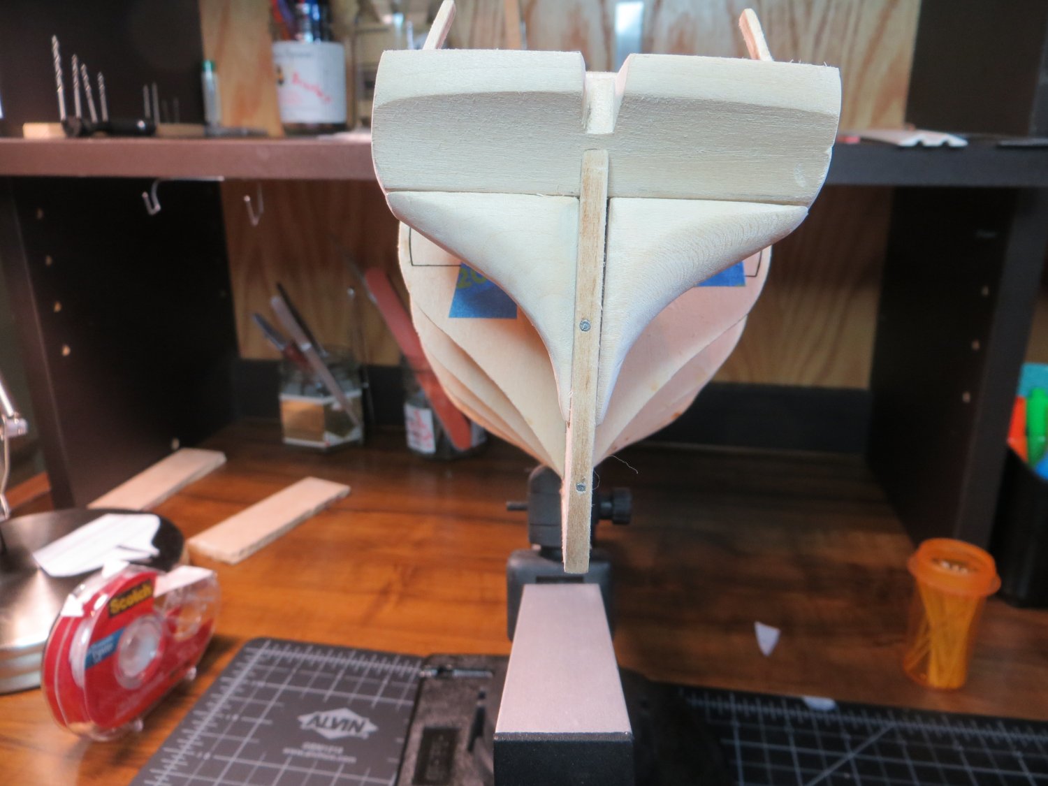
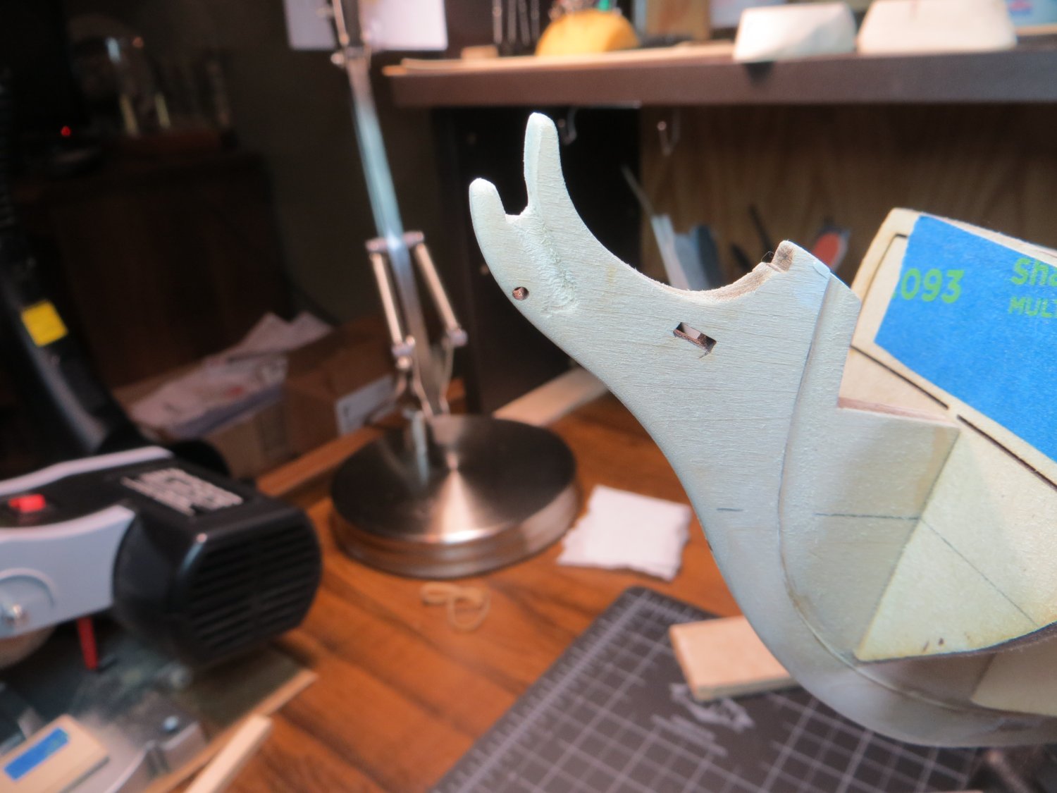
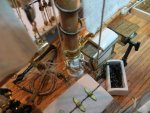
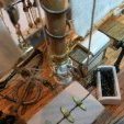
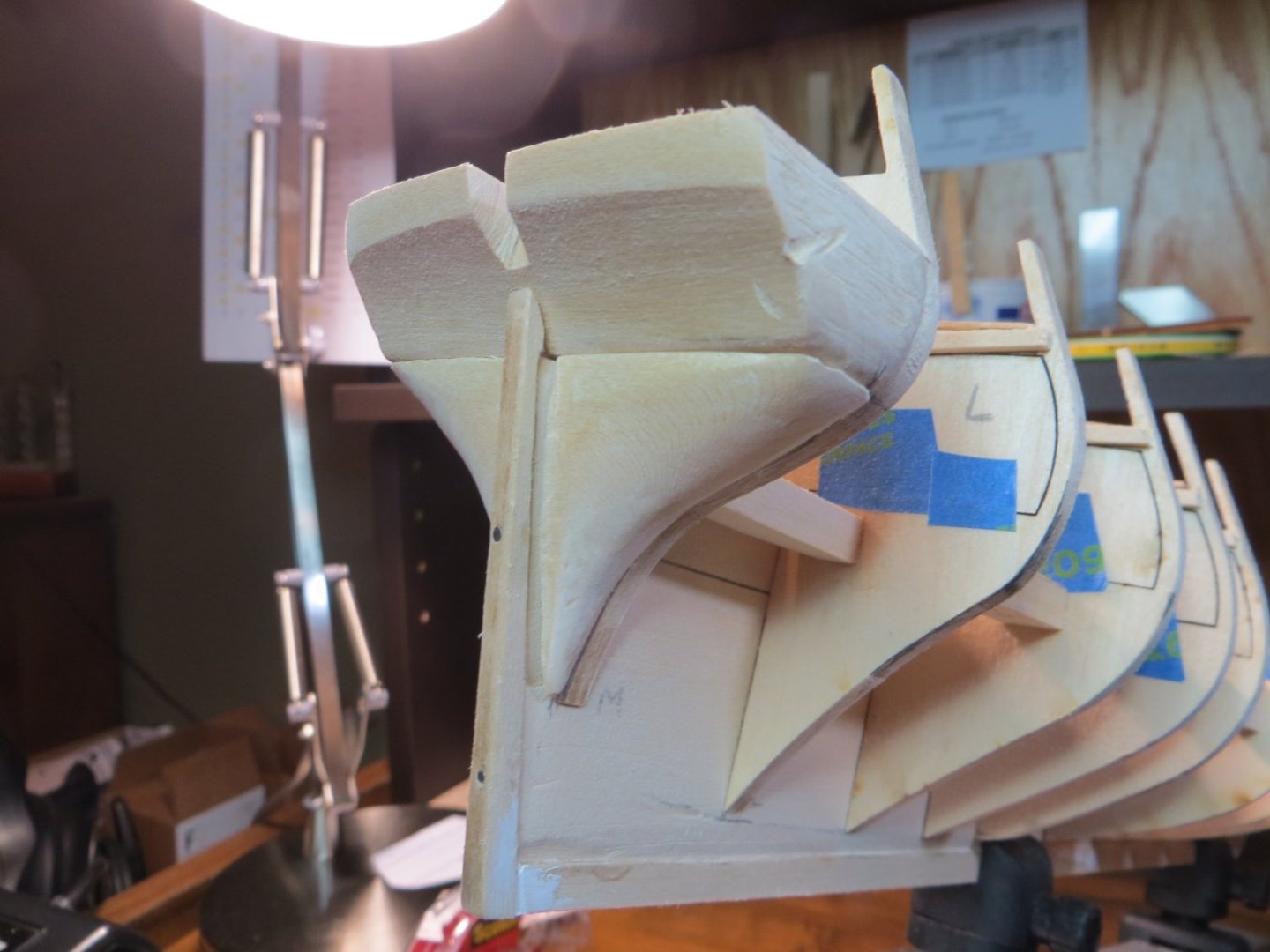
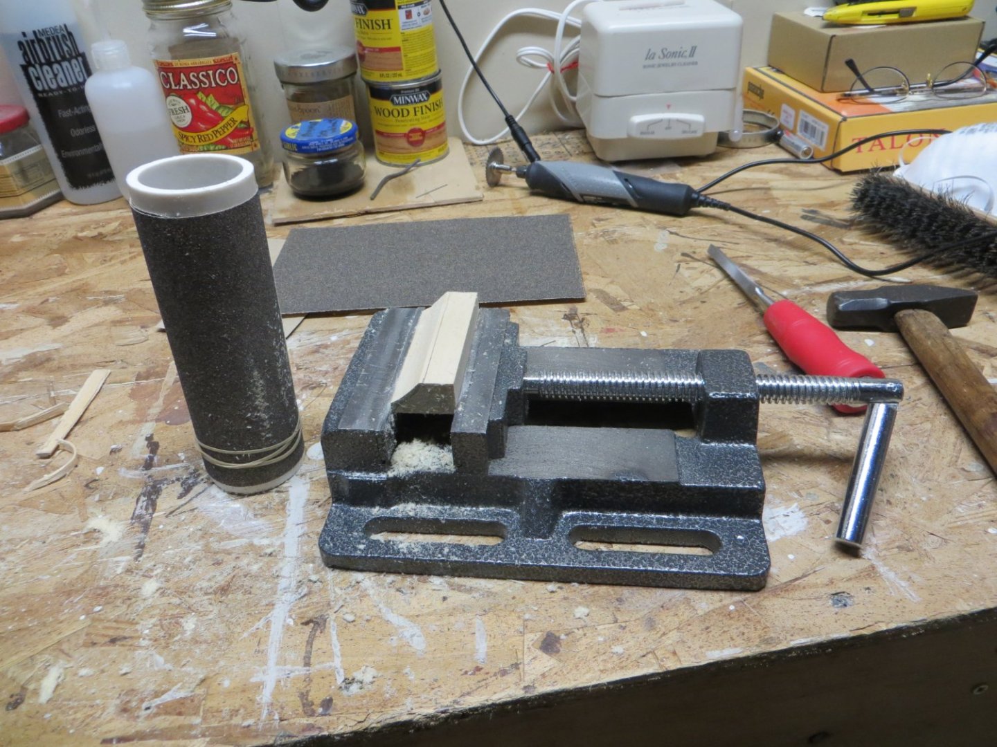
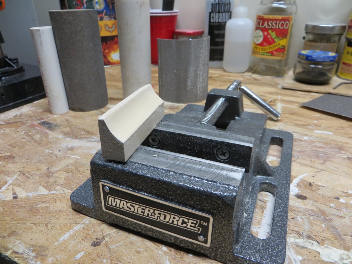
Step 9: Carving the Counter Block Carving the counter block wasn’t too difficult. I paid attention to what others have written in their logs. Make sure the block is long enough to reach from BHD M to the top of the curve in the sternpost. Be sure to create the slight curve which makes the transom bend slightly around the stern. I started with cutouts from the plans to pencil in the initial shape on the sides and top of the block. I left some extra wood for sanding down to the correct size. I used my mini-vise to hold the piece. I wrapped sandpaper around a couple of different sizes of pvc pipe to get the curved shape across the block. I used a larger one (~1-1/2” OD) for the initial shape. I found that a smaller 1-inch pipe allowed me to get the depth of the curve a little deeper in the middle. I used 80 grit to start and 120 to finish. Carving the angle on the top edge was a little tricky. I’ve done quite a bit more sanding and shaping since these initial pictures were taken. The final shaping will be done when I fair the bulkheads.


-
Dave, I'm not quite ready for the transom, but when I did a quick test fit with the carving, mine looks just like yours! I read someone's log where they put the metal in boiling water and then bent it open to fit!! I'm not looking forward to this step! My lower right inside edge looks even more gnarly then yours. I don't know how to fix that either. Maybe a metal shaping bitt on the Dremel? I'll be watching with interest to see how you proceed with yours.
-
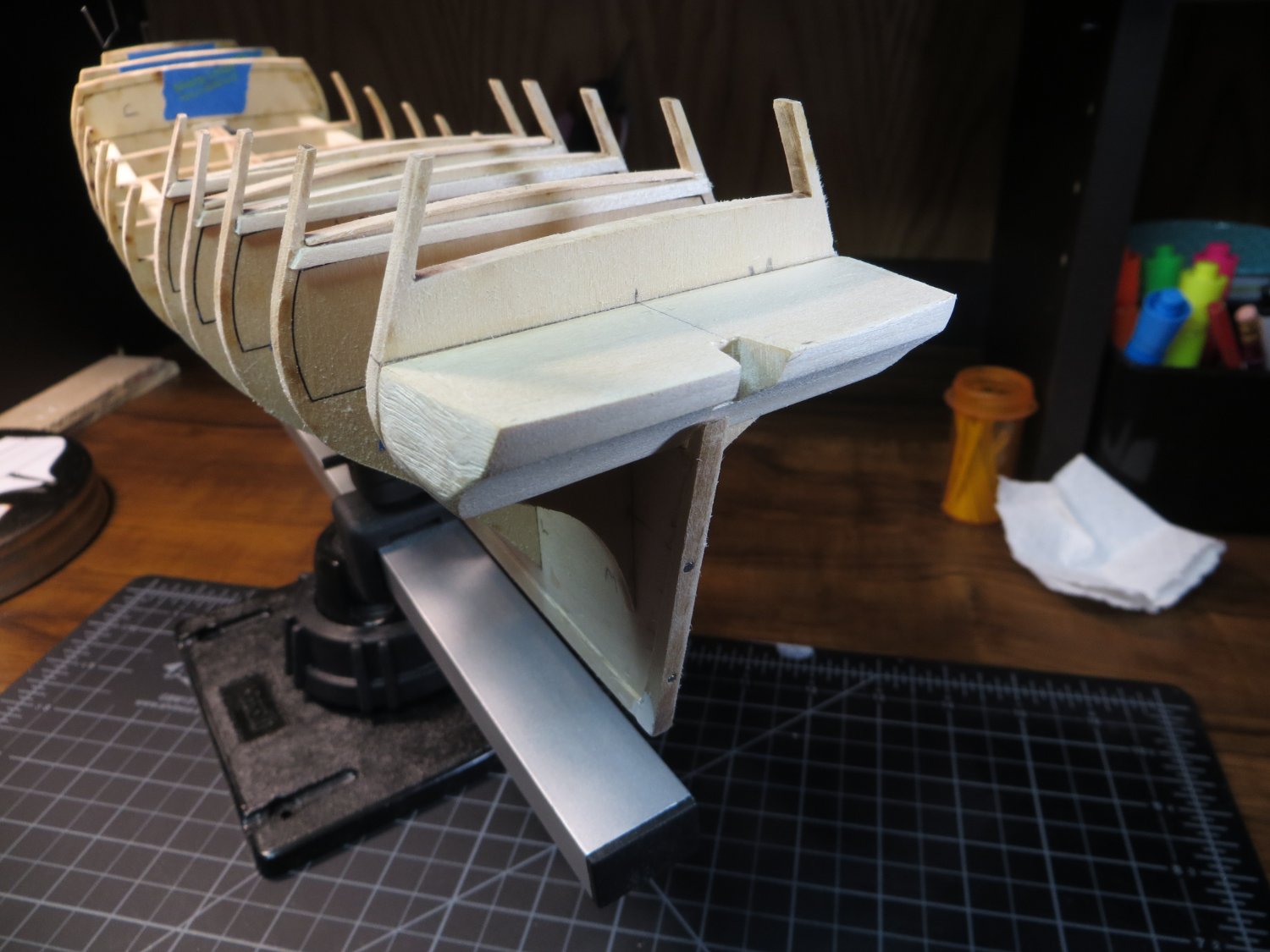
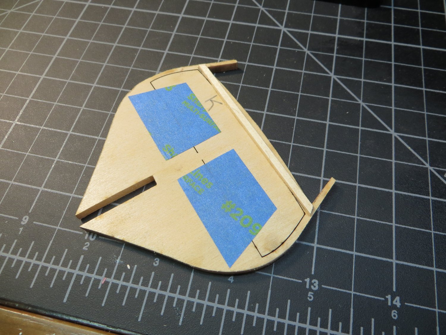
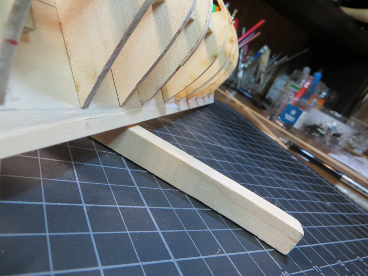
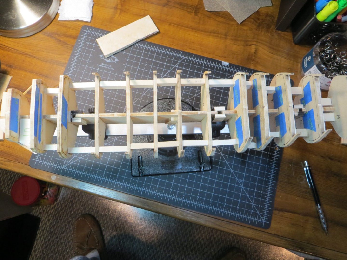
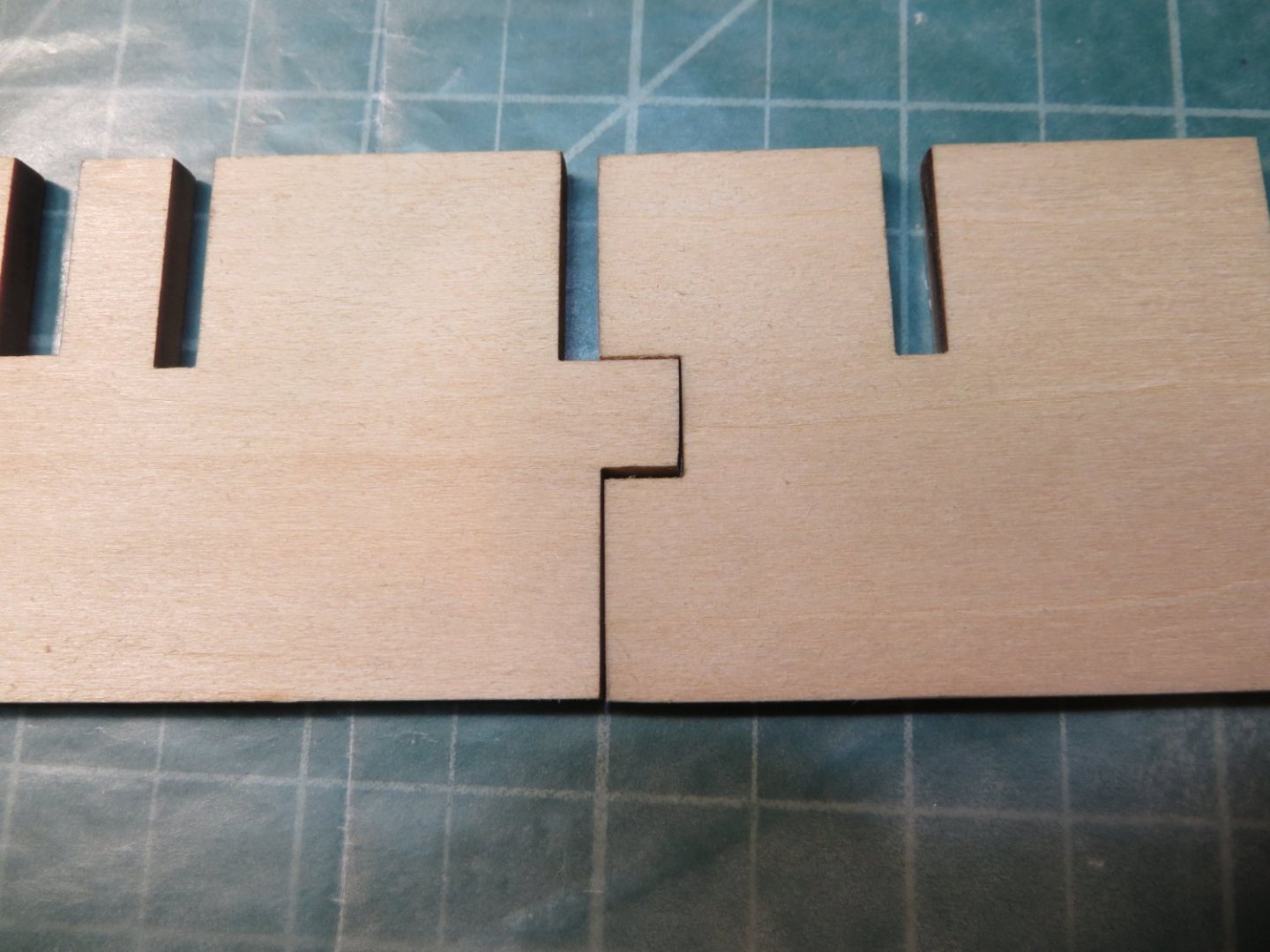
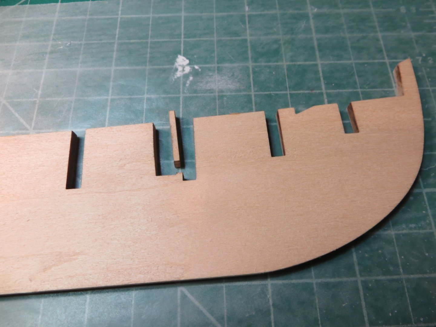
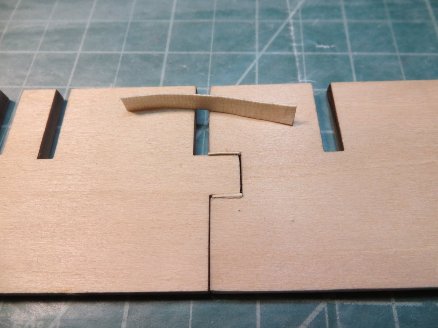
Step 7: Cover the Mast Slots Step 8: Carve Bow Fillers, Full size filler for A-B & Add BHD support blocks I just completed Steps 7 & 8 according to my plan. Step 6 was to glue in the bulkheads. I did that previously, but failed to identify it as such with the pictures. First I covered the mast slots before I added the support blocks. You can see the repair I had to do to replace the broken piece in front of the Foremast in the last pic. In order to stiffen the hull frame before I did any Fairing, I inserted support blocks between each BHD. I measured the space between each BHD as precisely as possible using my digital caliper and cut lengths of 3/8" x 1/4" basswood pieces. These were glued in between each BHD. I checked and double checked to make sure the 90 degree angle was maintained on both sides of the keel to avoid creating a banana shaped hull! At this time I also carved the Bow Filler Blocks that sit in front of BHD A. I used copies of the top and side views for these pieces from the plans. I traced these shapes onto the wood blocks provided in the kit. I used a combination of razor saw and coping saw to rough cut the shape and then finished with a 120 grit sanding drum & the Dremel for the final shape. I'm not totally delighted with the results, but I think I will be able to fine tune their shape during fairing. I think I'm going to need a little wood filler too. Afterwards I made a full size block to fit between BHD's A-B to provide more surface area for gluing planks around the bow. These 4 pieces will be glued in before fairing. I plan to use test battens to see where BHD's need to be shimmed or sanded as I'm fairing. The next step, Step 9, is to carve the Counter Block behind BHD M. I'm a little nervous about this step as it seems that a lot of other pieces depend on the shape of the counter to be correct! I'll happily accept any advice from the Rattlesnake seasoned veterans!


-
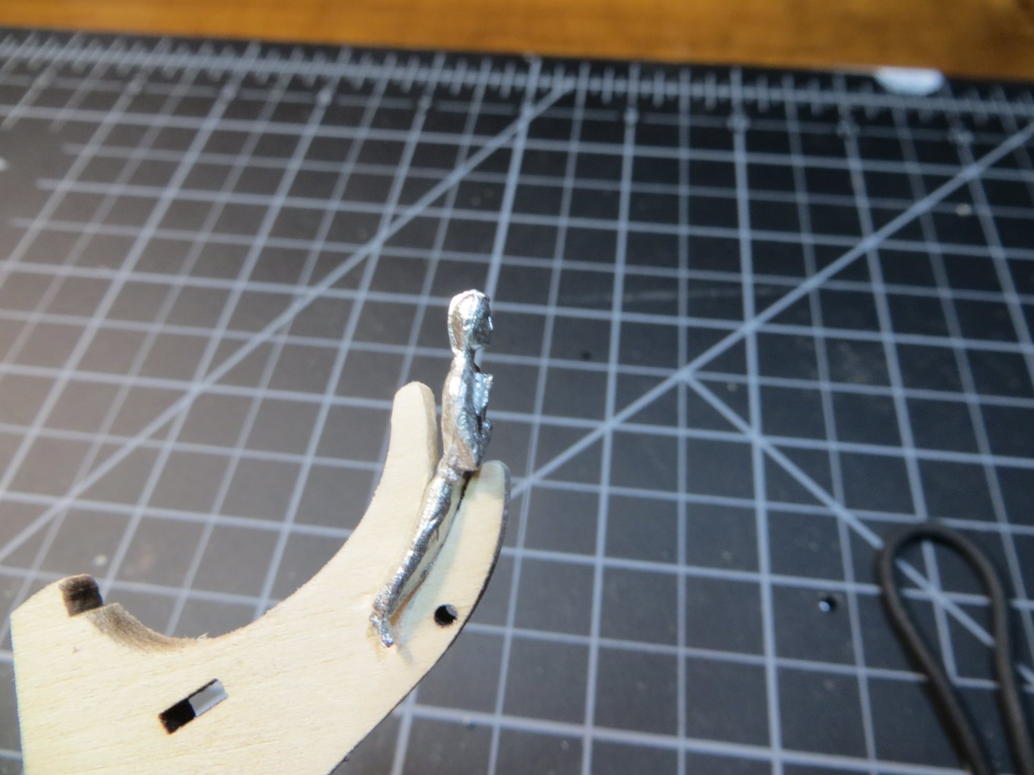
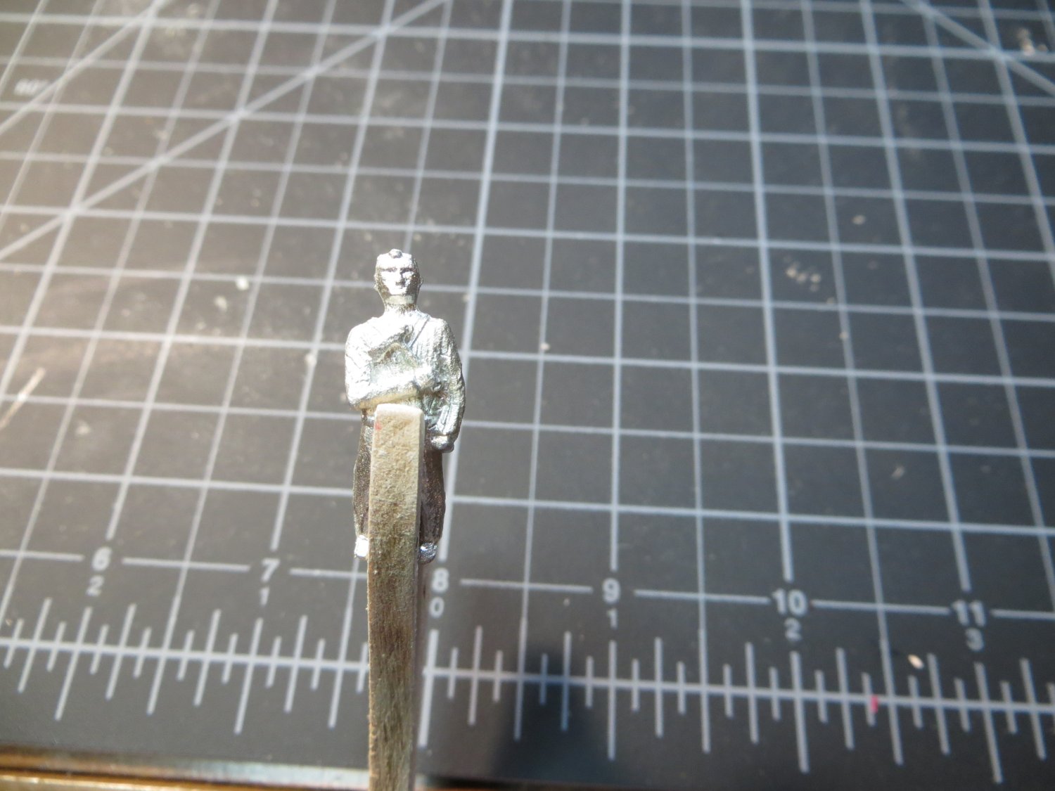
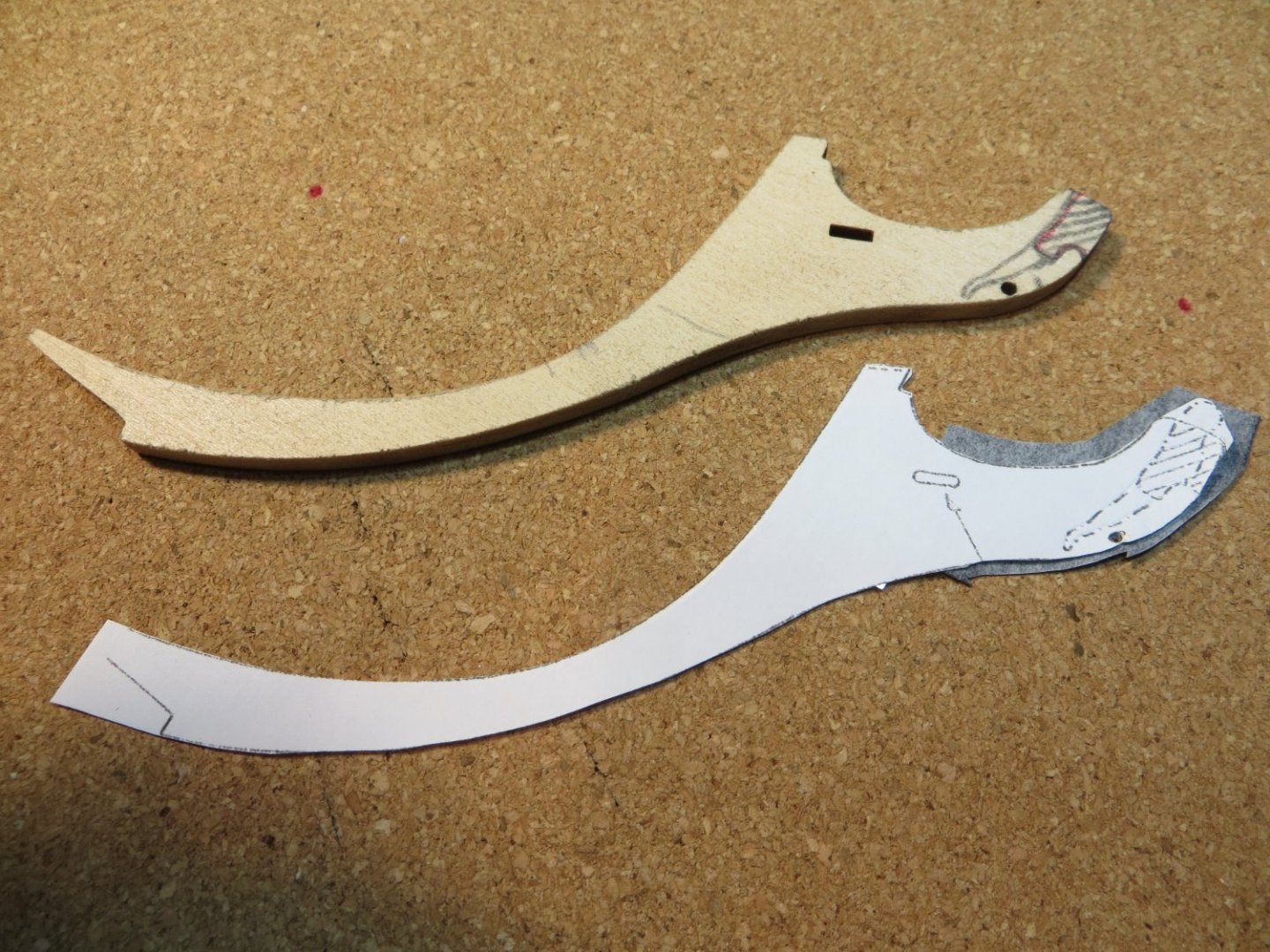
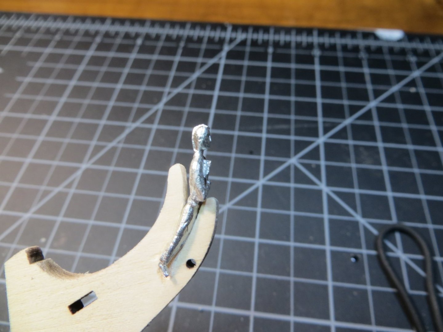
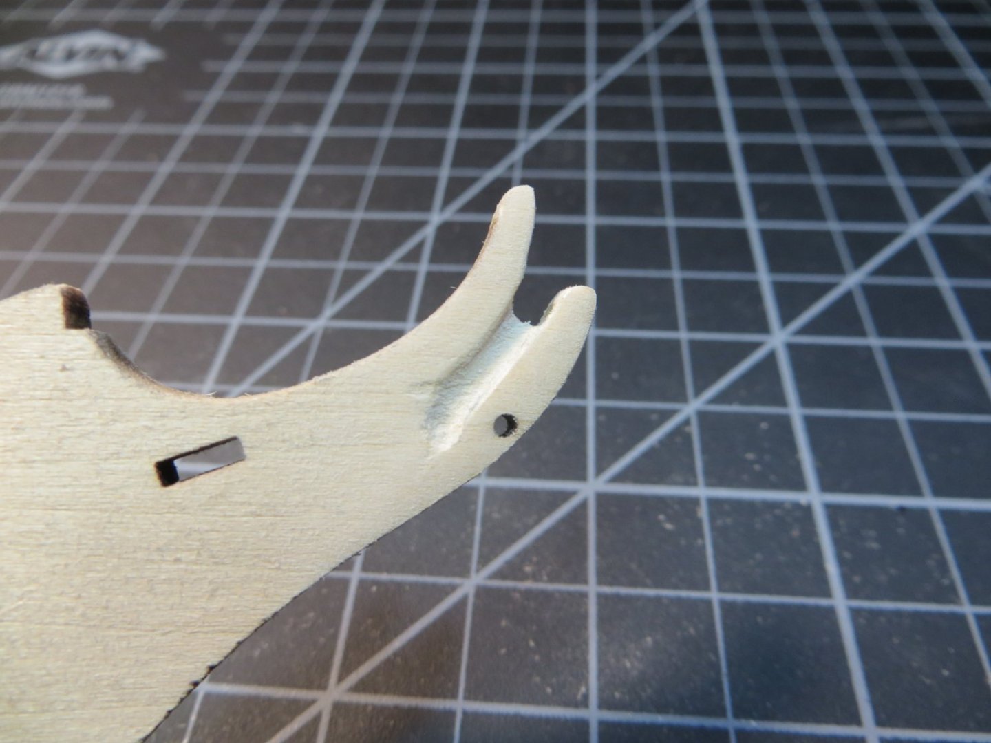
Hi Allan - Based on your input, I tapered and rounded off what is identified as the Stem in the Rattlesnake instructions/plans all the way up to the top. This is the area identified as the Bobstay in your drawing. I might shorten the part that sits in front of the figurehead a little bit further to expose more of his upper body. I'm afraid to taper that area all the way down. I think this will affect the bobstay which fits through the hole at the shin of the figure. Here are a couple of new pics. It's hard to get a good shot of the taper head on. I appreciate all of the detail you have provided on this section of the ship. Thanks, Ed


-
Hi Allan, The MS plans indicate that the figurehead should straddle the cut-out on the stem. I also read elsewhere that the taper stops at the waterline. Based on that and some of the pictures posted by other builders, I carved the stem the way I did. I hope I have not made a mess of it. I recall checking out a link to those archived plans in one of the other build logs I read a while back. I think its funny that the British did not remember that they already had a ship named Cormorant in their fleet and had to change the name back to Rattlesnake!
-
Hi Dave - did you maintain a slope from fore to aft on the quarterdeck? In other word, even the high/low spots but still have a slope from M down to I near the middle of the ship. M sits pretty high at the stern of the ship. It would take a lot to make M level with I. I don't think there's enough wood on that deck support to even do that! I think I'm misinterpreting Old Salt's comment on leveling the q-deck. Yes, I will be sure to maintain the curve toward the port and starboard bulwarks. Although that will be tricky! Hi Paul, thanks for jumping in. Unfortunately, this particular model from Model Shipways is notorious for having the laser cut bulkheads not match the measurements on the plans. I think I'm going to do what you said with adjusting to match a straightedge line from I to M. Same with A to C, with B needing to be shimmed upwards a bit. I would like to get some confirmation on this plan from the other Rattlesnake builders before I do anything I'm going to regret later!
-
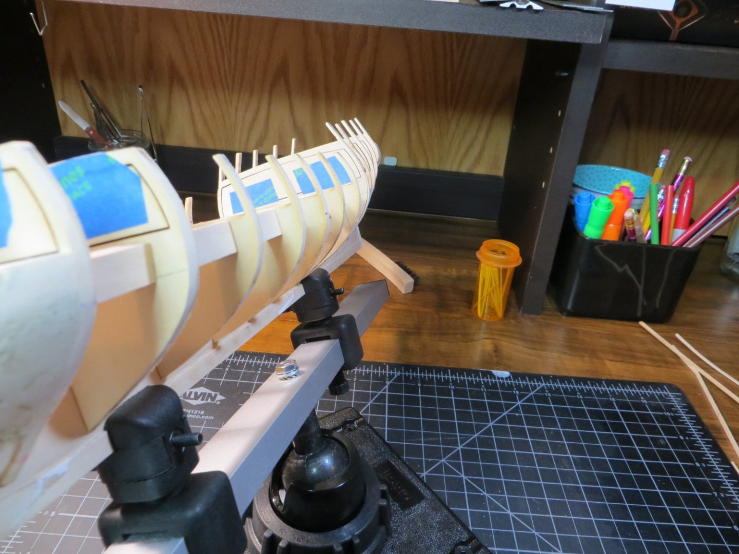
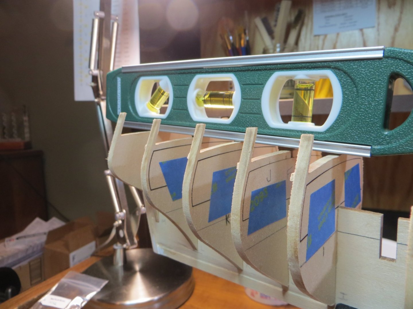
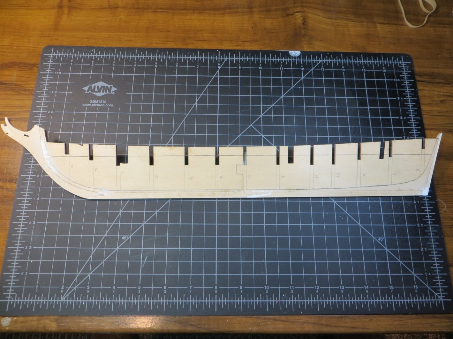
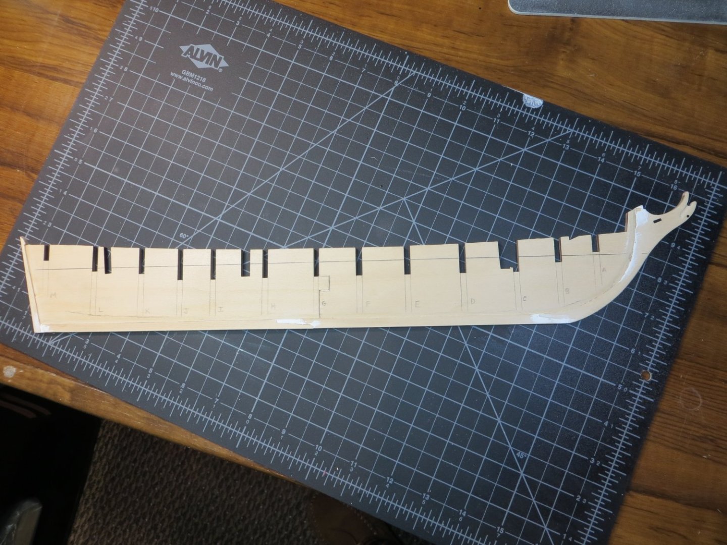
I NEED SOME HELP FROM THE RATTLESNAKE TEAM Old Salt in his build log said; “Shimmed bulkhead I for fairing and the top of bulkhead L so the quarterdeck will be level.” I have bulkheads on the quarterdeck that need adjusting. When I look at the blueprint plans it looks to me like the quarterdeck slops slightly toward the center of the ship. The raised fore deck also does the same, sloping aft toward the center. See the below pics of my quarterdeck and fore deck. B, I, J & L are all low. Or else A, C, K & M are high. My question is, should I attempt to level these bulkheads or fine tune them into a gentle slope to the center? The slope from M to I is pretty steep. What have you guys done about this? My bulkheads are set so that the gun deck at the bottom of the BHD inserts are all level with the top of the keel. Appreciate any advice! Ed
-
Step 5: Install the Bulkheads (BHDs) After removing the BHDs from the thickset I added some leftover 1/16” hull planking stripwood (from my last build) to provide extra support for the upper deck beams. I placed these on the “hidden” sides of the forward and quarterdeck. I have to give JPett credit for this tip in his build log. I also added a strip of painter’s tape to hold the BHD cutouts for these sections. This is all to help prevent breakage with these fragile parts. I removed the laser char using my new Dremel with a 120-grit sanding band. The next step was to dry fit the BHDs and use sanding sticks to get the proper fit and alignment. Sanding sticks fit perfectly into the slots of the bulkheads and keel. Using more advice from JPett, I used the deck line as the most important checkpoint. I also sanded the bottom on a few so they stopped at the beard line. The rest can be fixed later. Per advice, I marked the WL reference line on the BHD’s, but did not rely on it! Once everything was fitted, sanded or shimmed, I alternated from the center and used Weldbond to glue the BHDs in position. I like to use the grandkids Lego blocks to get the required 90-degree angles. Learned this from Dr. Per (Nirvana). Here are pics of the bulkheads glued in place before any “fairing”

-
Hi Dave, Just came across this build log for your Rattlesnake. I'm glad to see you got it started. I just started mine earlier this month. I'm not too far behind you. I just finished gluing the bulkheads. I look forward to following your build. It's too bad you are having trouble with the bulkheads. Issues with the framing seem to be SOP with this kit. I've had my share too. Great job on the anchor stocks. I might have to "borrow" some of your ideas there. It's great to have other modelers who are working on the same things you are! Keep up the good work!!
-
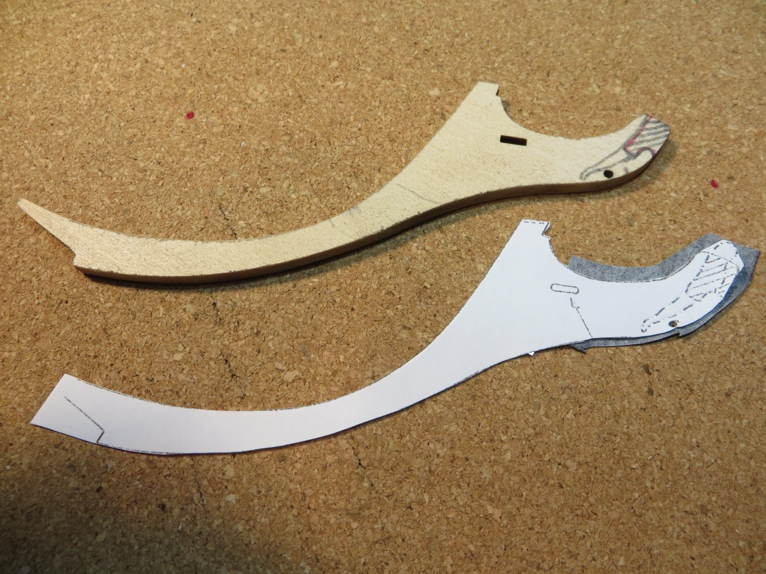
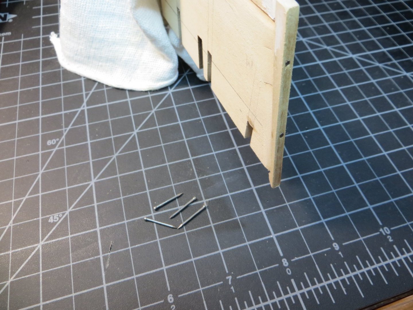
STAGE A: FRAMING THE HULL Alright, it’s time to get this party started! I experienced the same problems that everyone else has documented in their MS Rattlesnake build log. I’m not going to spend much time on these things, since they’ve been covered extensively by other builders. For those who are unfamiliar though, things like the fit of the 2 center keel parts are off, bulkheads don’t match the size and shape on the plans and don’t fit into the keel slots properly. The curve of the Stem does not match the keel. These are all fixable problems, but it’s too bad that Model Shipways can’t clean this up after all these years! Oh well, I guess it’s part of the lore of building the MS Rattlesnake! Step 1: Glue the 2 Center Keel Parts & Mark the Bearding Line, WL & extend BHD slot lines The Center Keel parts don’t fit. It’s important to shim the top and bottom of the slot so the deck level and bottom lines are aligned and even! I also created some of my own problems. Like snapping off the skinny little peg between BHD C and the fore mast when attempting to dry fit this bulkhead! I decided to fill this gap with a wider spacer after gluing this BHD in place. Step 2: Prepare the Stem before Installing The Stem does not fit and needs to be sanded very carefully until the shape fits the curve of the keel bow. I took a little bit off both the stem piece and the keel at the bottom part of the curve until it would lay flush. I used the new Dremel I got for my birthday last summer to carve the slots for the figurehead. I used a copy cutout of the stem and some carbon paper to outline the position on both sides. Then used a jeweler’s saw to rough cut the top section out before carving the slots on each side. Step 3: Glue Stem, 2 Keel Parts & Sternpost to Center Keel I prepared the parts by dry fitting and doing some light sanding. I also decided to insert a few dowels, as recommended in the instructions, to better secure the parts to the center keel. I was afraid the thinness of the keel after carving the Rabbet could be a problem. I used some 3/64” x 5/8” finishing nails as dowels. I drilled a pair of holes in each of the 4 parts on my drill press. Then added pilot holes into the center keel using a pin vice after I glued the 4 parts to the center keel. I use Weldbond glue on all the framing. When everything was dry and secure, I used Tamiya putty to fill any gaps in the fit. The instructions say to taper the stem before installing, but I decided it would be better to do this after it was attached to the keel. Pic of the keel after step 3 but before cutting the rabbet Pic showing the nails used as dowels around the keel It's difficult to get a good picture of the tapering of the stem. But here's a couple of pics. It widens out to the full 5/32" above the waterline and at the lower curve of the stem. Step 4: Cut the Rabbet On my first ship, this step scared me to death! It’s still scarry, but considerably easier the second time around. At least you understand how it’s supposed to work! I did not go quite the full 1/16” on each side that is required yet. I’m going to wait until I start fitting the garboard strake to do the final sanding. Pic of the keel after cutting the rabbet The next step is installing the Bulkheads (BHD’s).

-
Hi Kenneth, Yes, the people on this site are a great help. Having 1 previous build helps provide confidence, especially at the start of the P-O-B build. The steps are very similar. I just checked out your build log. Looks like you've persevered for a while now! And the end is drawing near for you. Your ship looks amazing! Look forward to following along. Thanks, Ed
-
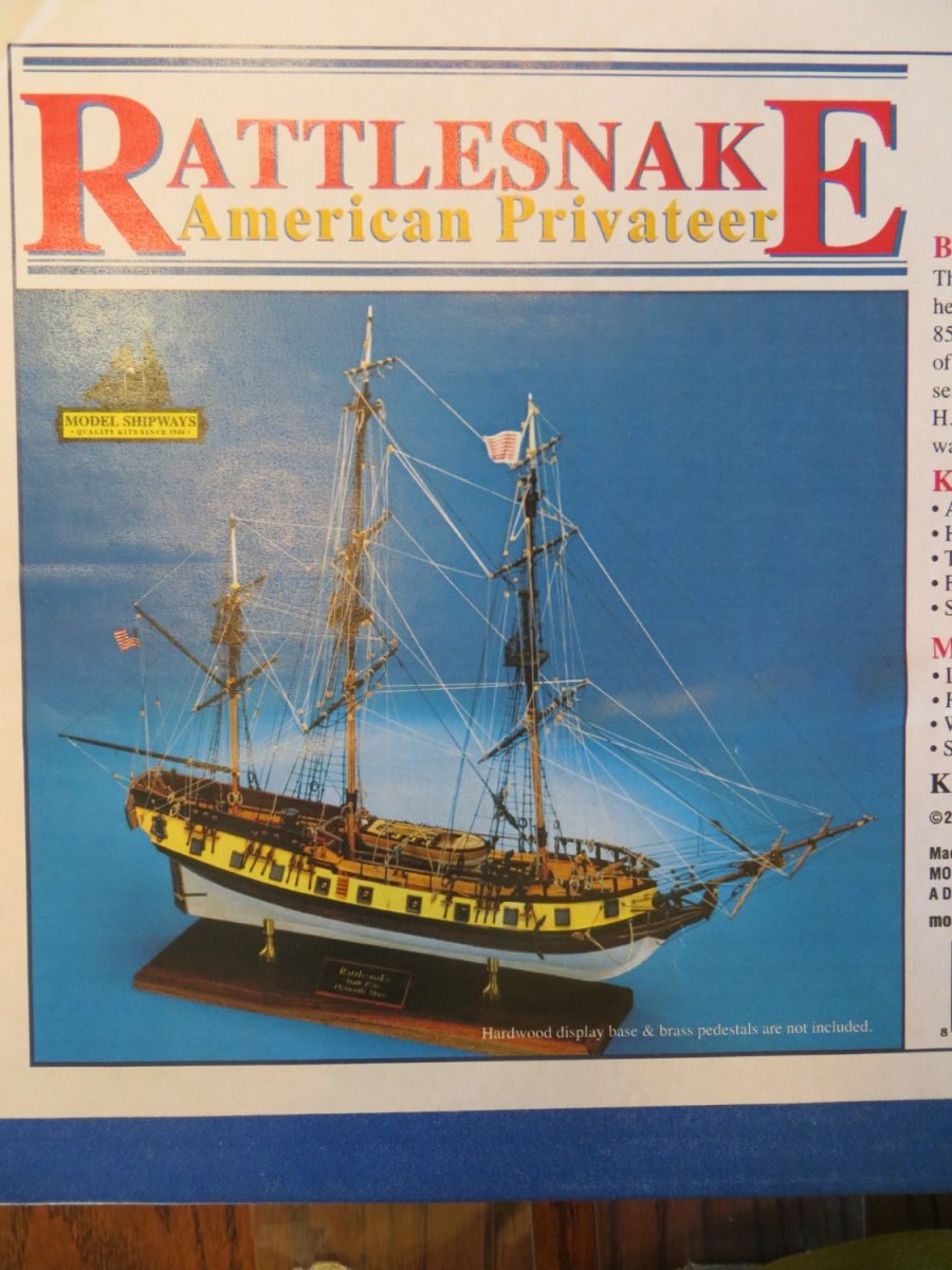
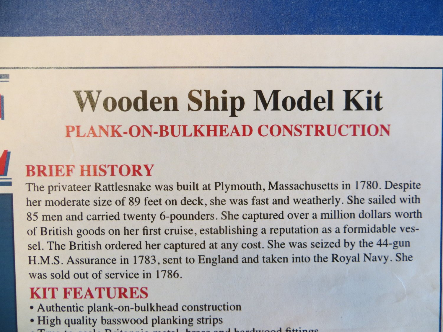
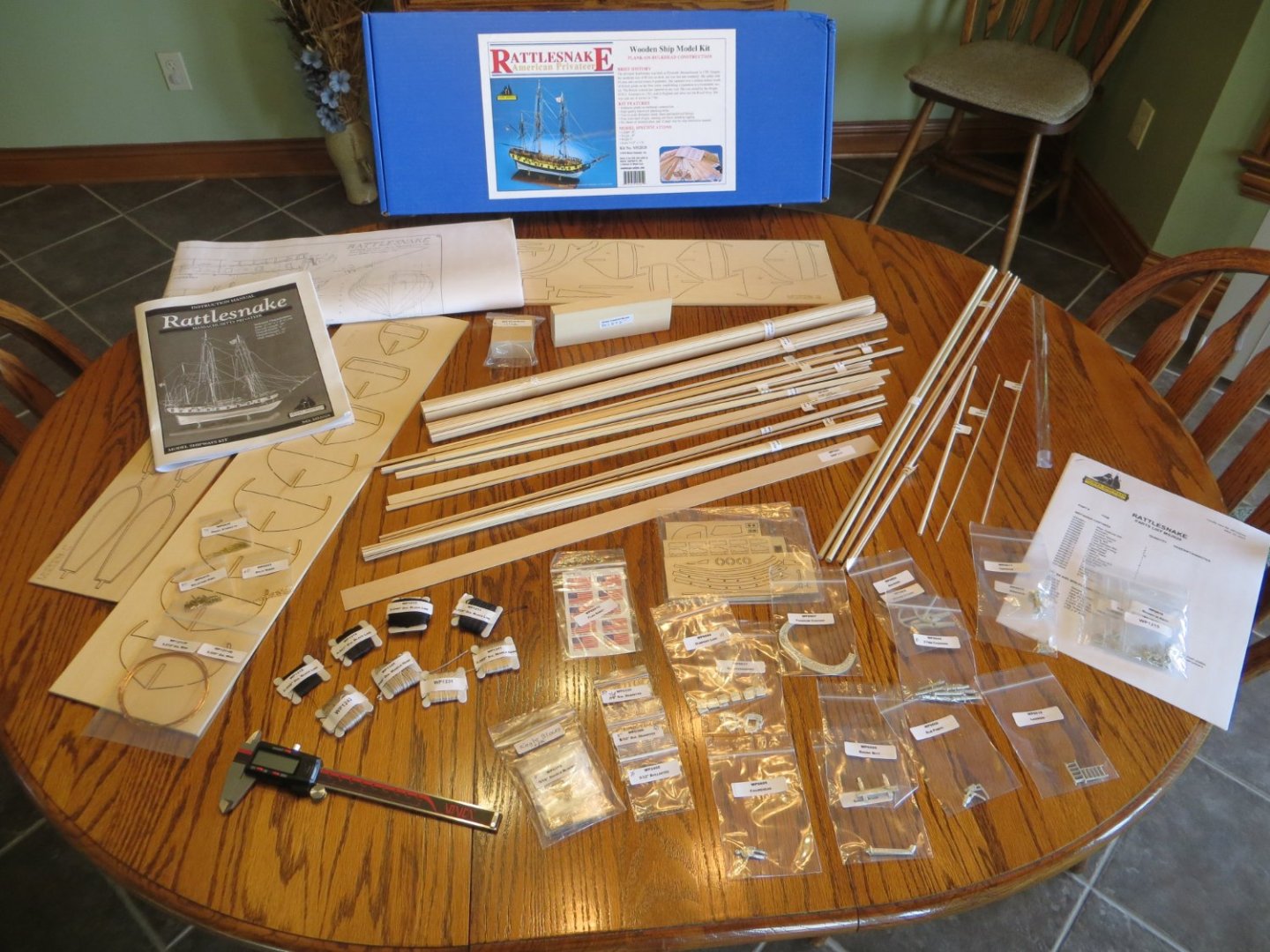
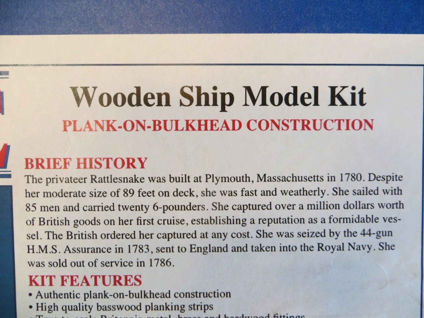
Introduction Rattlesnake is my second model build. I finished Bluenose 1 back in June. This took me 2 years to finish. I decided to take a little summer break from modeling before starting Rattlesnake. I think that it was a good idea to give modeling a rest because I am now very eager to go. I consider my “official start date” as October 8th. In August I completed inventory of the kit. I also spent a lot of time throughout 2022 studying build logs for Rattlesnake and putting together my own build plan & instructions. I created an Excel spreadsheet to compare the instruction manual from Model Shipways, the plan I used for Bluenose and several build logs from this MSW website. Using all this information, I created my own plan. I thought about purchasing the Bob Hunt Practicum from Lauck Street Shipyard. But after reading JS Gerson’s build log, I decided not to. The Mamoli kit seems to be quite different from Model Shipways and I’m not ready to do a major kit-bash. I do plan on buying the masting & rigging practicum from Lauck Street. But that’s a ways off!! I share this thought process for anyone who is considering how to proceed with their own Rattlesnake build. I look forward to sharing my build log with you and I encourage you to share any comments or words of wisdom that will help me with this project! Thanks! Here are a few pics showing the completed inventory and the kit box cover:

-
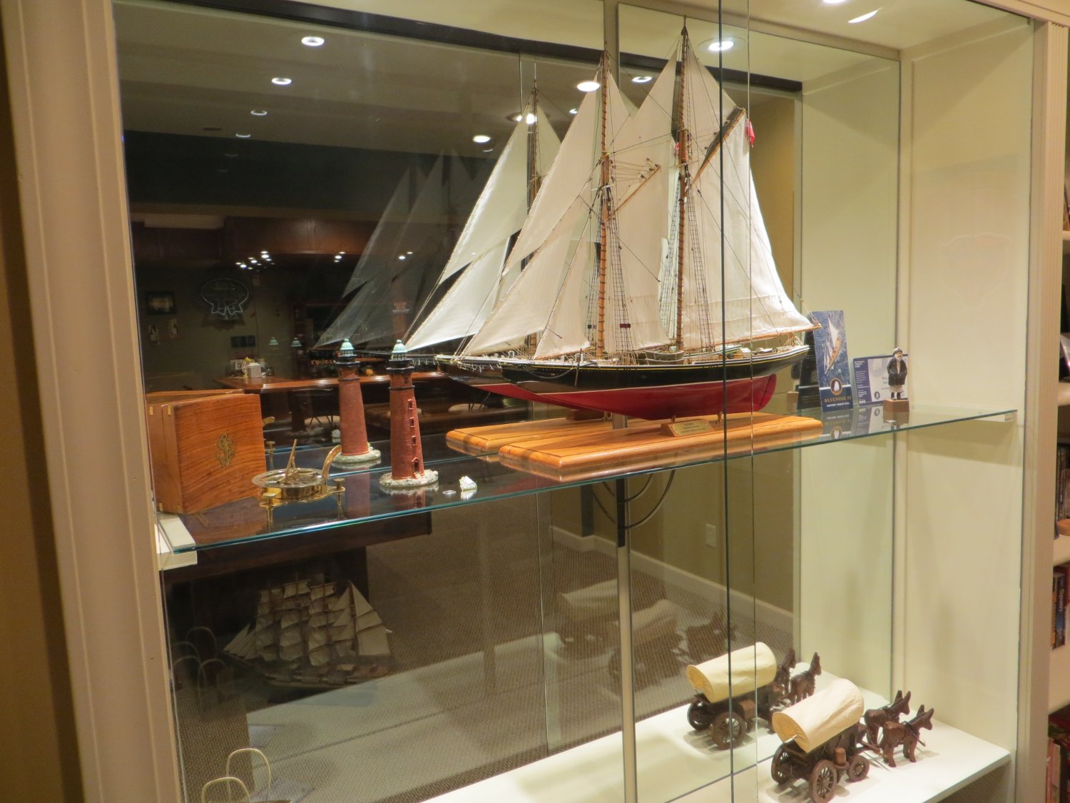
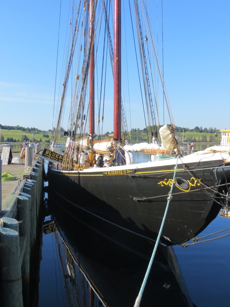
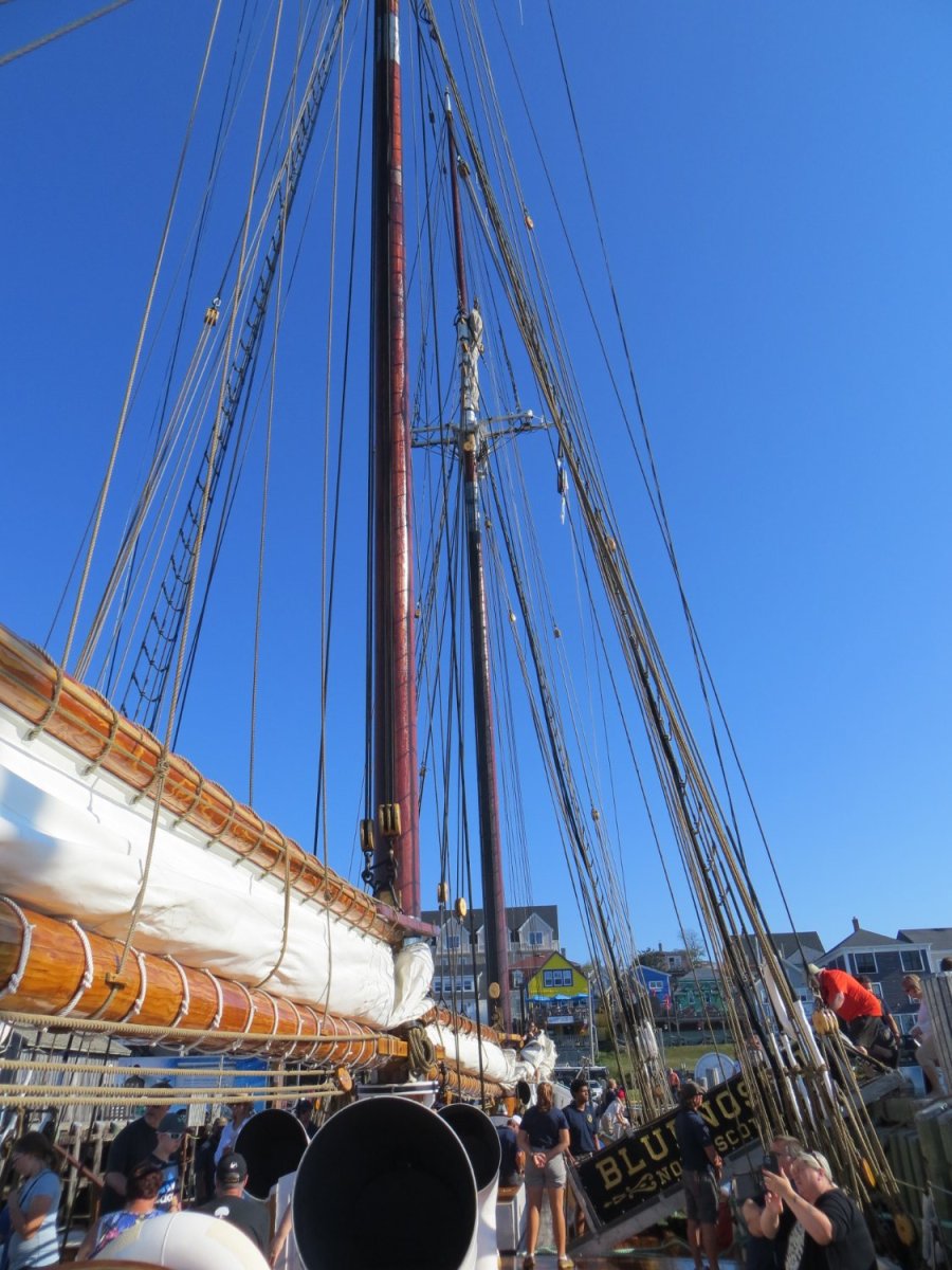
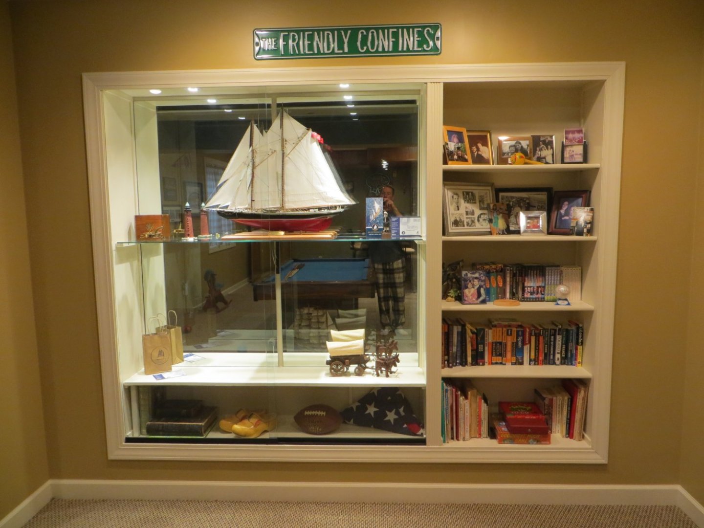
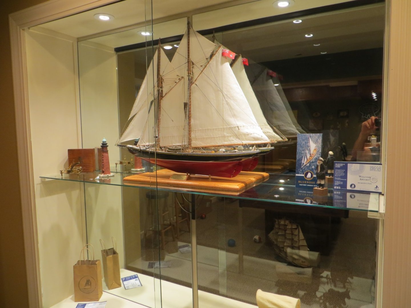
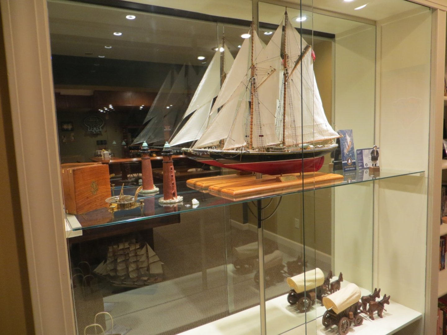
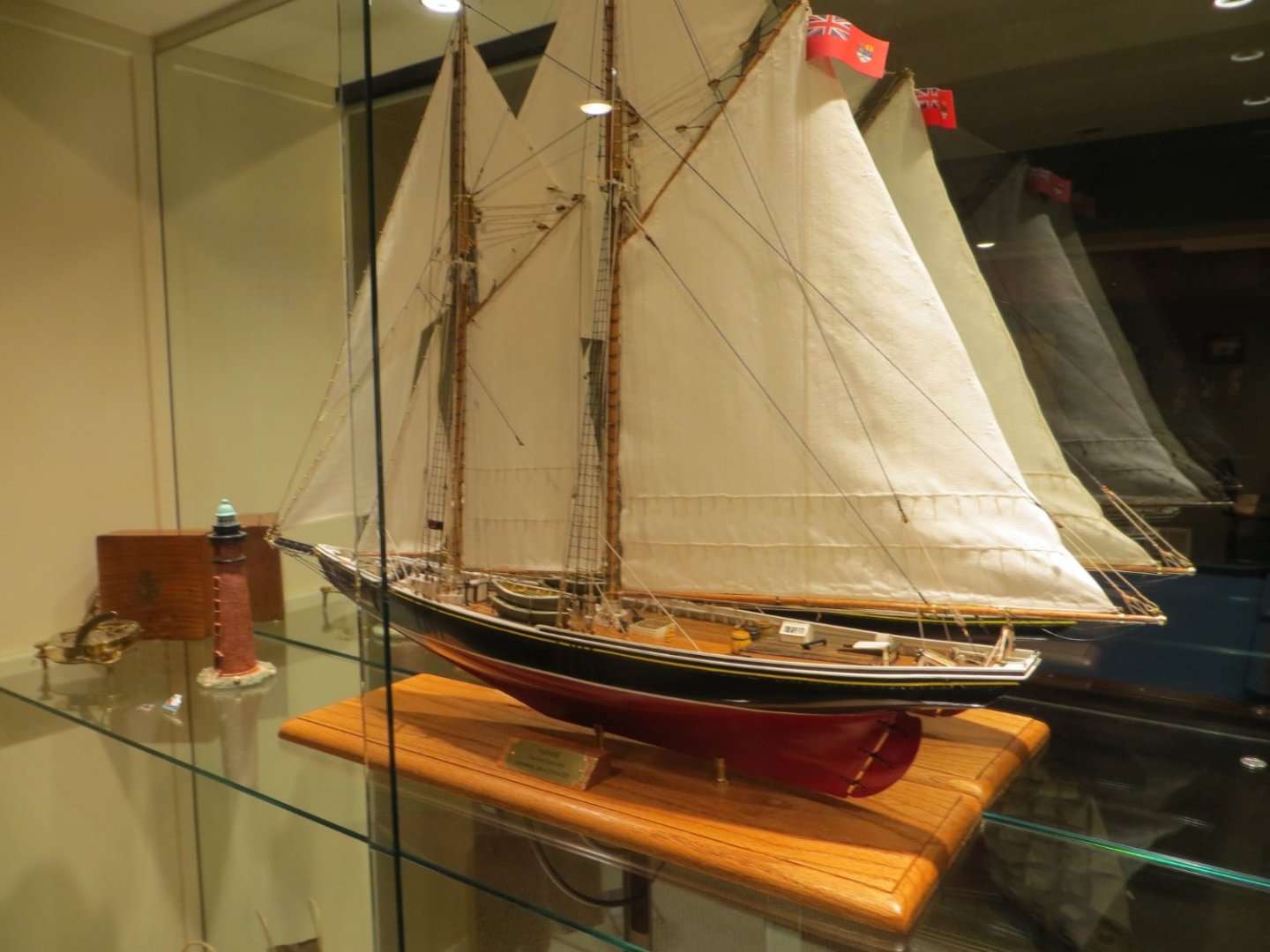
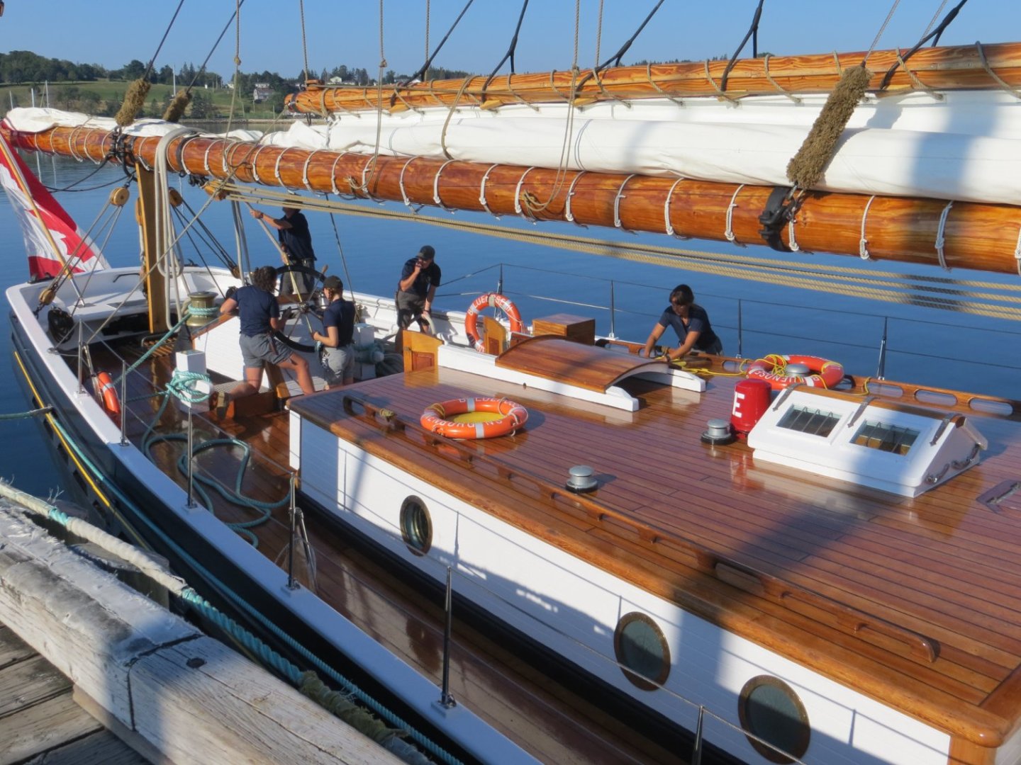
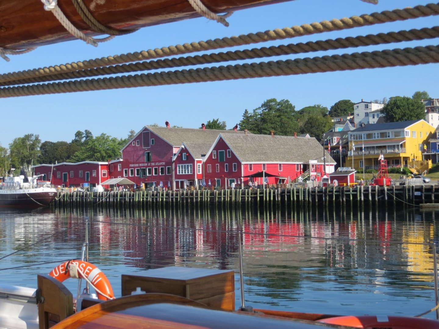
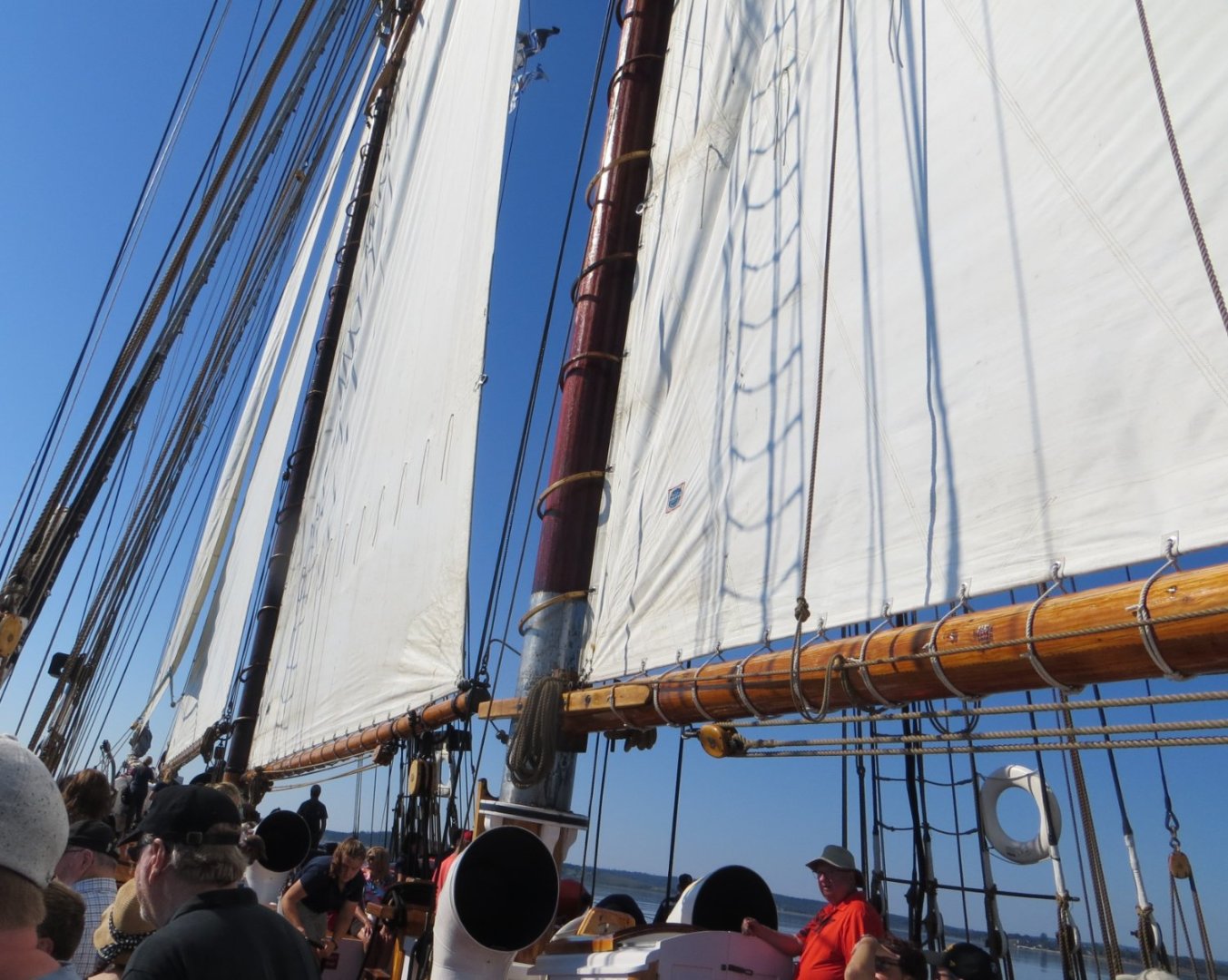
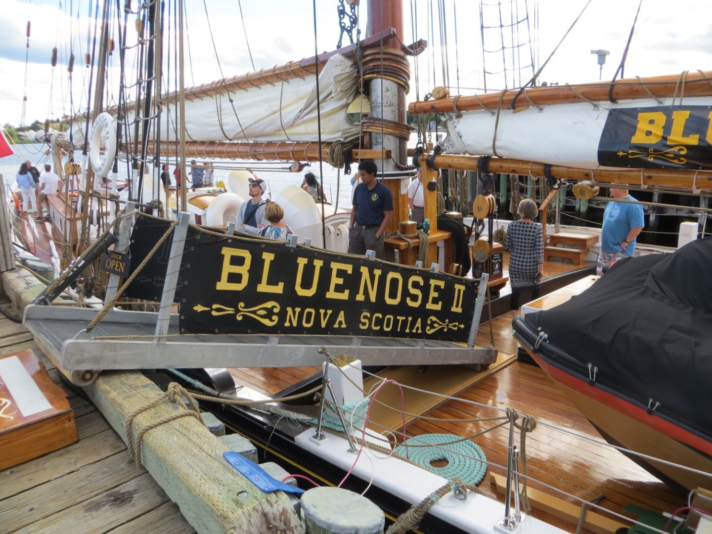
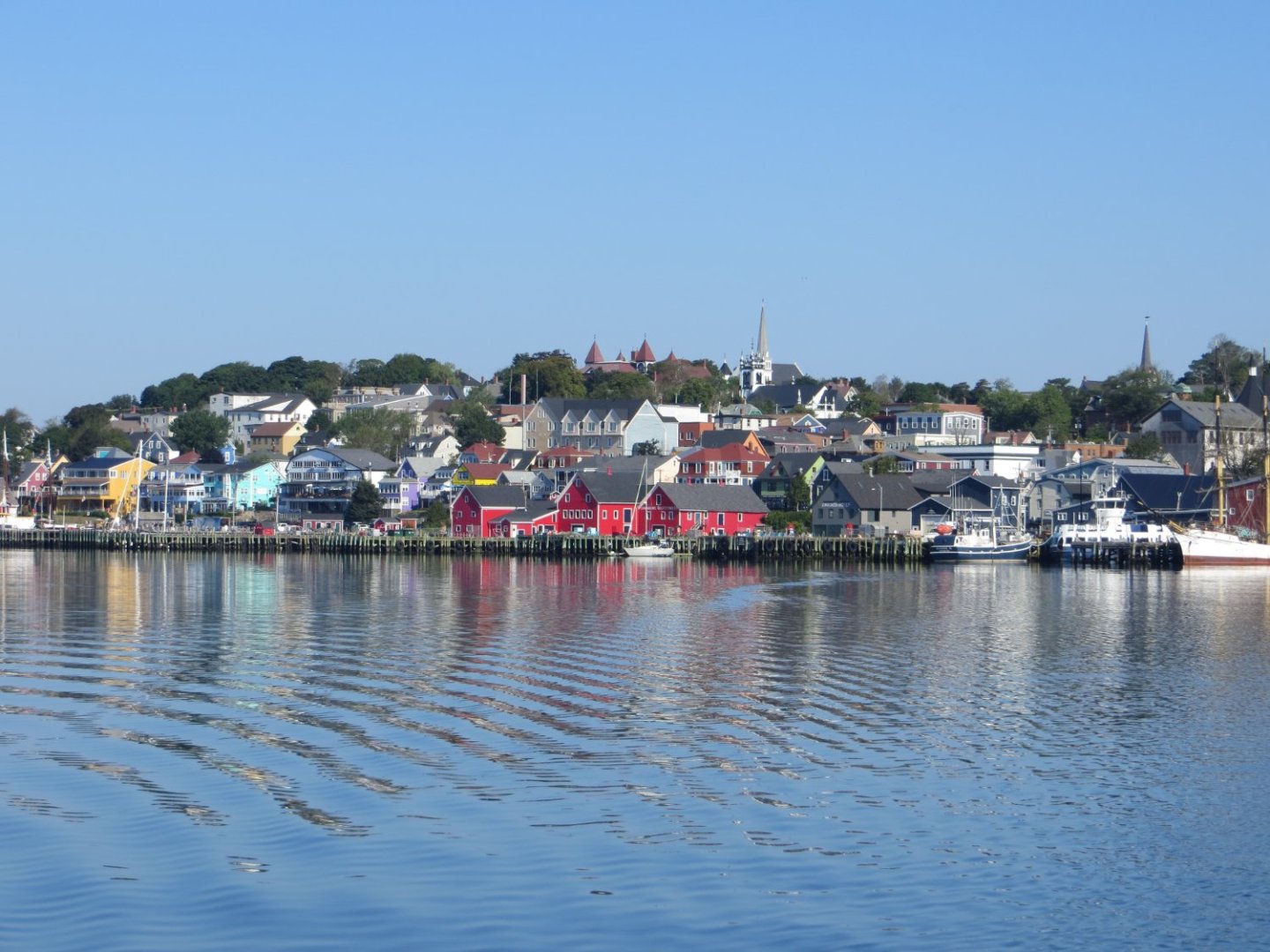
Hi Guys, I wanted to share with you some pics of the display case that I built for my Bluenose. It turned out to be quite the project. I converted 2 of the 3 sections for a built-in bookcase in my basement to display my ship models. I designed it to hold 4 ships. Purchasing the custom mirrors and glass cost more than it did to start-up this hobby!! But now I have a dust free environment for her. I'm also throwing in a few pictures of Bluenose II from our vacation to Lunenburg Nova Scotia. Since it's related to Bluenose, I hope I'm not breaking any rules!! If someone would like to see something in particular of the ship message me. I've took a bunch of pictures. I even know what a "Baggywrinkle" is now!! I never added any of these and there's a lot of them on Bluenose II. After taking a few months off, I got Rattlesnake "off the shelf" and have started my build. Will be starting a build log very soon, if you are interested. This model is very different from the fishing schooner. Best of luck to all you Bluenose builders out there. I hope my log is of some benefit to you. Best regards, Ed BLUENOSE I MODEL DISPLAY CASE SAILING ON BLUENOSE II in LUNENBURG, NS


- 96 replies
-
- 6
-
-

-
- model shipways
- bluenose
- (and 1 more)
-
Thanks Ron! I am in the process of converting a built-in-the-wall bookcase into a display case. It will have glass shelves, mirrors, down lighting and glass doors on the front. I will post some pictures when it's completed. Definitely get back to your Bluenose. It's a beautiful ship!
-
Dave, the parts list in both of my MS kits (Bluenose & Rattlesnake) does say "Jewelry Nylon".
-
Dave, the MS line in my kit was identified as nylon. I did not do anything special to my line before using it. But, I applied a generous coating of beeswax to every piece I used. Make sure to run it through your fingers several times to press it into the line and remove the excess. This is supposed to help protect the lines and also keeps the knots more secure. Dilute white glue is for treating the knots so they do not come apart. This is supposed to be better because it does not turn stiff like CA does. I would not recommend coating the lines with it. I think it would make a mess!! Well, I tried using the dilute PVA on knots initially, but had zero success. These knots kept untying on me. Plus it takes forever to dry! I switched to thin CA early on. I made myself an applicator from one of those long thin straight pins. I bent a tiny hook at the end to hold a dab of CA, snipped off the head and inserted it into a dowel. This works great for me! Sometimes I used Old Salt's method of applying a touch of ca on the ends to keep them from unraveling. But, if you are trying to thread a block, it makes it more difficult. You either have to cut it on the angle or roll it in your fingers to make it thin enough for the larger line sizes. I hate getting that glue on my fingers! I used one of those needle threaders for sewing to thread most of my rigging.
-
Hi Chris! Welcome aboard. The forecast for the Chicago area for tomorrow is 95 degrees!! MSW is a great forum for getting help and guidance with your ship building endeavor. I just completed my first one last month. So, you are in good company. The best way to get feedback is to maintain a build log for your project. Best of luck to you.