HOLIDAY DONATION DRIVE - SUPPORT MSW - DO YOUR PART TO KEEP THIS GREAT FORUM GOING!
×

.jpg.6c90d67e7e9071af590f4d4a2a8bc908.jpg)
Waldemar
-
Posts
984 -
Joined
Content Type
Profiles
Forums
Gallery
Events
Everything posted by Waldemar
-
.thumb.jpg.c6343966b029e7941df5b987d129aac6.jpg) Yes, and yet in this case, it is the harmonious division of diagonals, as described in French works on naval architecture, and not the parabolic method of shaping frames. I admit openly that in this case I made a mistake in identifying the method, and my only (un)justification is that I unforgivably jumped to conclusions without a complete analysis of the case, as should be done and as I usually remember to do. Sorry. However, the other comments remain valid .
Yes, and yet in this case, it is the harmonious division of diagonals, as described in French works on naval architecture, and not the parabolic method of shaping frames. I admit openly that in this case I made a mistake in identifying the method, and my only (un)justification is that I unforgivably jumped to conclusions without a complete analysis of the case, as should be done and as I usually remember to do. Sorry. However, the other comments remain valid . -
This must be the outline of the fore quarter frame, which has special significance in the design. The set is completed by the aft quarter frame, but this almost coincides with one of the regular bends and has not been drawn separately.
-
At least it's good that it's ‘Wildmanden’ and not ‘Berserker’, because that would be already a blatant promotion of intoxicants...
-
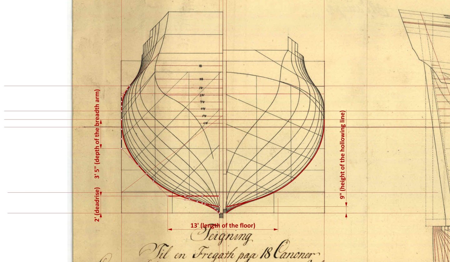
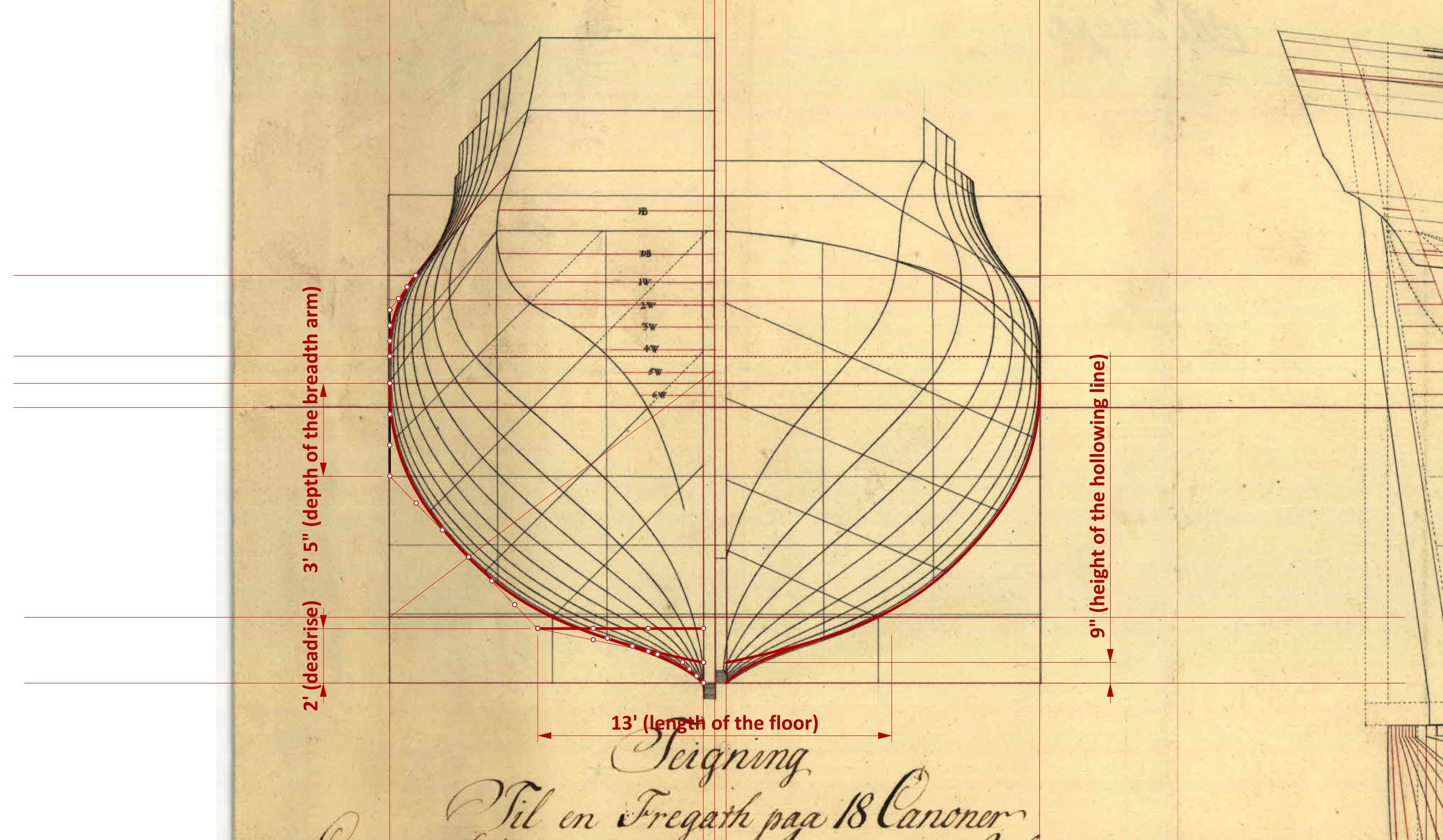
Hi Arthur, I wholeheartedly wish you success with this project, but I must honestly warn you that it is a design based on the (double) parabolic variant of the Northern design method (incidentally, the same method was employed by Joshua Humphreys to design the famous American frigates). This, at the time, was a very popular, widely used design method all over the Northern Europe, dating back at least to the last decades of the 17th century, for example for the design of Dutch warships and merchant vessels. The French transport ship La Belle 1684, which sailed to what is today USA territories, and recently excavated by archaeologists in the Gulf of Mexico, was also designed using this method, although the archaeologists failed to recognise this feature and, as a result, wrote nonsense about this particular aspect in their monograph on the ship . And the same can be said about the French monograph by Ancre on this ship. I specifically mention this to make you aware that you will not be able to rely on modern historical, archaeological or other works in this field, and you will have to refer directly to sources from that era in case of need, especially works by Swedish naval constructor Fredrik Henrik af Chapman may be helpful here. Anyway, the design method employed by Turesen means that not a single pixel of the frame contours in this particular design is a straight line or even a regular arc of a circle, whether for the underwater part of the hull or for the upperworks. Well, maybe except for a very short section at the widest point of the hull. To put it bluntly, these circumstances may kill your attempt at reverse engineering of this particular project, especially without your extensive experience to date. But perhaps even more importantly, this plan, which at first glance looks indeed very good and seemingly complete, in reality lacks the most important elements that form the actual basis of the design, namely the line of the floor, the hollowing line and the line of maximum breadth, and you will have a very hard time to recreate them, which is a must. Admittedly, it is possible to find these fundamental design lines, especially on such a precisely drawn plan, but it is a real challenge for me as well. Not to mention such ‘trifles’ as the hull being aligned to the horizontal waterline rather than the horizontal keel. This detail is obviously not already an insurmountable obstacle, but it slows down the work considerably and can easily cause various annoying inaccuracies. And I won't even ask if you already have working CAD software (and which one specifically), which is absolutely essential for such projects, because I'm afraid of the answer . A regular vector graphics software for creating usual illustrations is not suitable. It's not that CAD software replaces knowledge of geometry, because it doesn't, but it offers tools that allow you to use those skills efficiently. If I haven't managed to discourage you with the above , then below, to make your start easier, some absolutely basic and essential data that are so desperately lacking in the dimensional specifications of the ship and on the original plan itself. But this is only the very beginning of a very arduous journey, because these are only the dimensions relating to the master frame... And, by the way, may I ask about your native language?
-
Indeed . On the other hand, however, one can be pleased that they have survived as a species to this day, despite several centuries of relentless slaughter, unlike many other species...
-
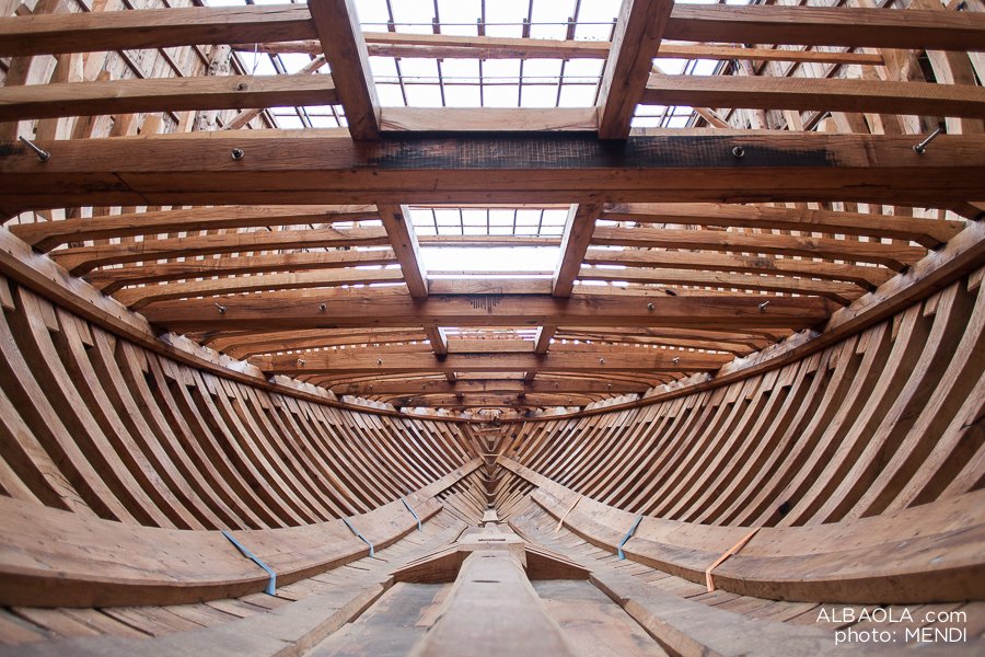
At first, I did indeed think that it was the second replica, precisely because of the long time that had passed since construction began. In these circumstances, I referred to photographs from the construction site, where this very aspect looks much better than on the video. And most importantly, it is close to the original. Below are the relevant graphics for comparison. Anyway, I am looking forward to seeing the results of the sailing trials of this replica.

-
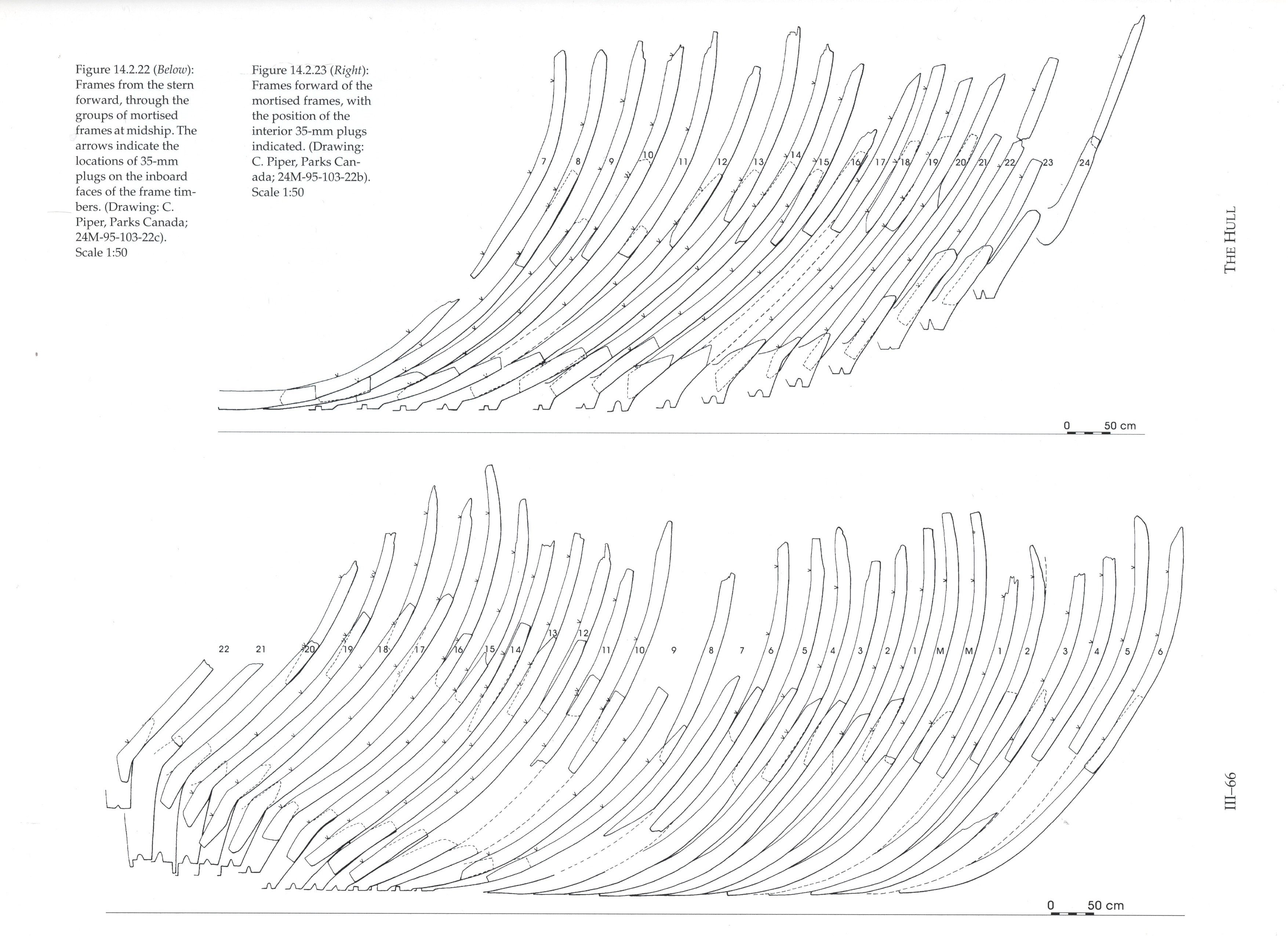
Indeed, I wish it were just an optical illusion caused by the black colour of the bottom, which literally devours light. When it comes to assessing the sharpness of shapes, this can of course be considered quite subjective and relative. Relative, because a sharp bow for relatively long hulls may not be sharp enough for very short ships, such as the San Juan. Either way, I would be interested to see the results of sailing tests of the finished replica in this regard. Unfortunately, archaeologists have not made a conceptual reconstruction of this important wreck, or at least they have not published these attempts and their results in a multi-volume archaeological monograph by Parcs Canada. The published lines plan is merely the result of smoothing the hull shapes by synchronising cross-sections, waterlines and possibly other lines of this kind (apart from the construction of a 1:10 scale archaeological model, in which the shapes were faired by eye), but this is not how ships were designed at the time and cannot be considered a conceptual reconstruction, but only an attempt to approximate the original shapes using later methods.
-
Is this a second replica of this iconic ship, built by the Basques themselves? The video seems to show that the hull of the replica is much too full, especially at the bow, in the gripe area, for a ship of such short relative length. This suggests a very leeward ship that does not hold its course, which, incidentally, is quite typical of today's replicas of ships of this type and from this period. Yet, in this particular case, almost the entire hull of the original has been preserved, which could have been used as a model, and it is unclear why its lines has been so badly deformed to the detriment of the replica's sailing properties.
-
HMS Falken - little sister of HMS Wasa
Waldemar replied to Nirvana's topic in Nautical/Naval History
Yes, it looks promising in a full-fledged publication. In the past, I might have missed the design concepts for this ship, but recently, out of necessity, I have become self-sufficient in this particular matter . -
Yes, this is very good museum practice. You can immediately see which parts are original and which are modern replacements. There is also another school of thought, quite the opposite, which prefers that the replaced elements be indistinguishable from the original ones next to them.
-
Review Le Coureur 1776 - Shipyard 1:72-scale Laser-Cut Card Model Kit
Waldemar replied to catopower's topic in REVIEWS: Model kits
There is another explanation, even more likely. The differences in the hull shapes on both plans from that era are due to the fact that although the British were able to measure the hulls of the captured vessels very accurately, already when drawing up their plans, they were, in a sense, designing such vessels from scratch, but using different design methods, which inevitably altered the actual shapes of the hulls to a greater or lesser extent. Not to mention the natural deformations of the hull during the ship's use. This is why today's French researchers consistently reject the lines from such plans of captured ships, preferring instead the original plans by the French designers (if, of course, they have a choice). And rightly so, and this is the first exception to this rule that I am aware of. For the above reasons, the original French design plan should be considered more reliable in terms of the shape of the hull, rather than an approximation made after the ship's capture using other design techniques that are incompatible with the original ones.- 12 replies
-
- 3
-

-
- Le Coureur
- Shipyard
- (and 1 more)
-
Either way, from what you have just shown, there is still a lot of dubbing to be done on normal frames. Just like in real-scale construction!
- 133 replies
-
- 3
-
-
- ancre
- Bateau de Lanveoc
- (and 2 more)
-
Hi Jacques, I've been following your thread and I can see that lately it's been an unnecessary road through frustration leading to disappointment . If I may suggest, shape the surfaces of both ends of the hull in the same way as the original builders did. Start by removing the cant frames (although one pair at the stern may still prove useful, choose one of them in this case). Prepare and attach 5 or 6 ribbands/battens per side. Keep an eye on symmetry, especially at the ends of the hull, but a slight asymmetry will not be the end of the world, just as it was not in real vessels. Only then shape and secure the cant frames, guided by the battens, preferably using temporary paper templates. Alternatively, instead of battens, you can try normally planking the hull right away, and only then shape and attach the cant frames, already more to reinforce the structure than to shape the surface. What do you think?
- 133 replies
-
- 2
-
-
- ancre
- Bateau de Lanveoc
- (and 2 more)
-
Intentional skewing of the bowsprit and beakhead seems rather unlikely, as the bowsprit runs exactly over the stempost (unlike, for example, English designs of the period, where the bowsprit ran alongside the stempost, always or at least often) and there was no reason to angle them in the horizontal plane. This arrangement is particularly evident in Björn Landström's fantastic illustrations in his equally fantastic book The Royal Warship Vasa, published in 1988. I highly recommend consulting this publication as well.
-
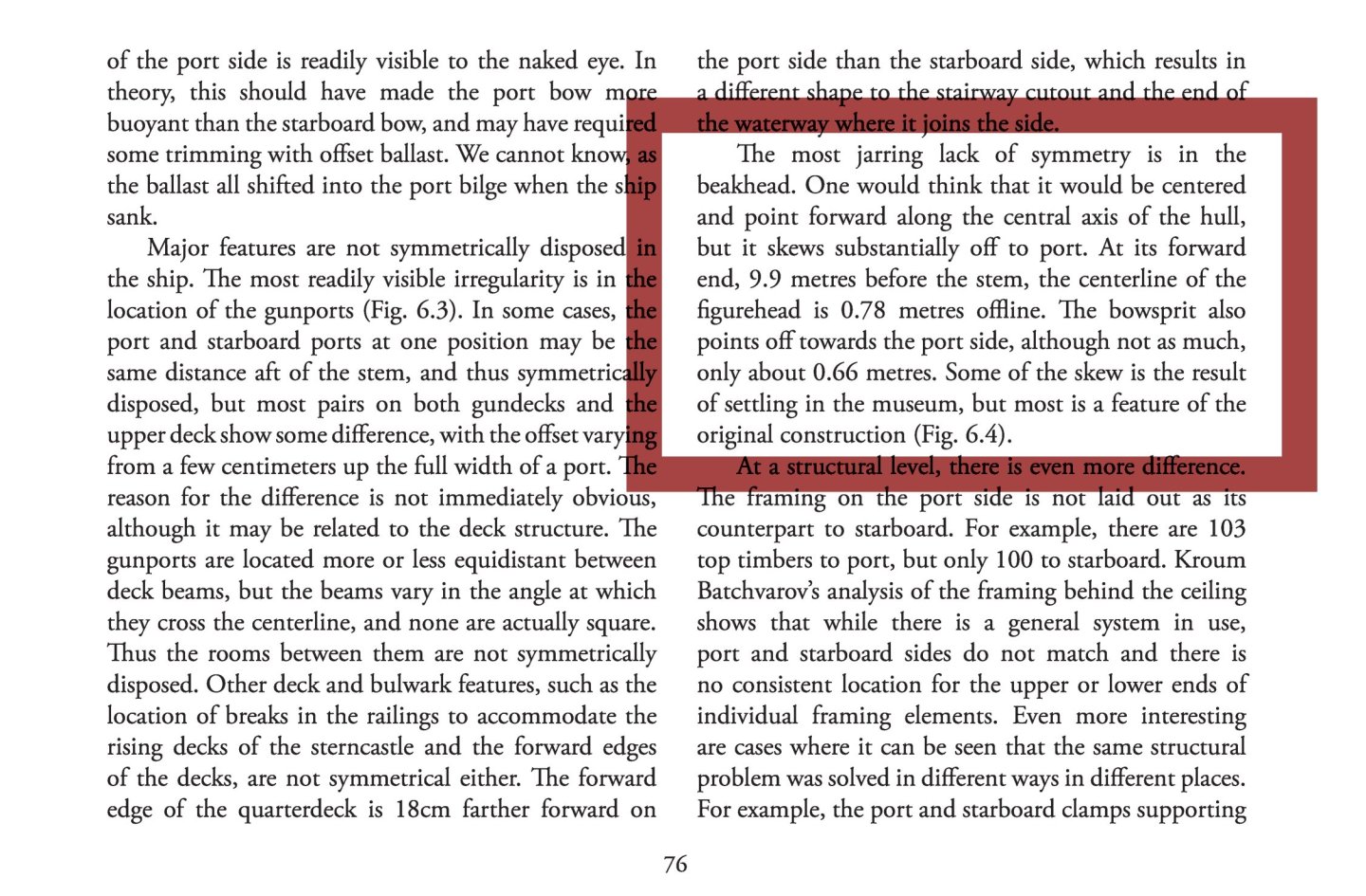
In this particular case, as in many others, I suggest taking a look at the relevant commentary in the article referred to. The entire section on the various asymmetries of the Vasa's structure is both interesting and informative, and here are a few paragraphs, including the one on the beakhead:
-
This will probably be the first model of the Vasa 1628 that I know of that will (intentionally) incorporate all the known defects and flaws of this vessel. I am particularly curious to see how the distortion of the beakhead will look in the photos of the model. It can be said that this rather conspicuous feature is never reproduced by model makers, so I commend the courage to do so. Not everyone may know what this is about, so below is an illustration showing the beakhead distortion as it appears on the original (from a paper by Fred Hocker, In Details Remembered. Interpreting the Human Component in Shipbuilding, 2013). In fact, this very feature was omitted even in the official plans of the ship published in 1980, and there is still no updated set of plans.
-
As for your fundamental decision to build a model with all the flaws of the original, I actually agree with it and it would probably be my choice as well. I think I would even make a crooked beakhead like in the original, instead of a straight one. On the other hand, my diagnosis of the causes of these errors would be different. For example, it is known that the chief designer's successor realised during construction that the design was flawed and tried to remedy it, but unsuccessfully, and even these ‘rescue’ attempts introduced further errors with disastrous consequences. As it happens, other designers and builders at that time did not normally make these mistakes.
-
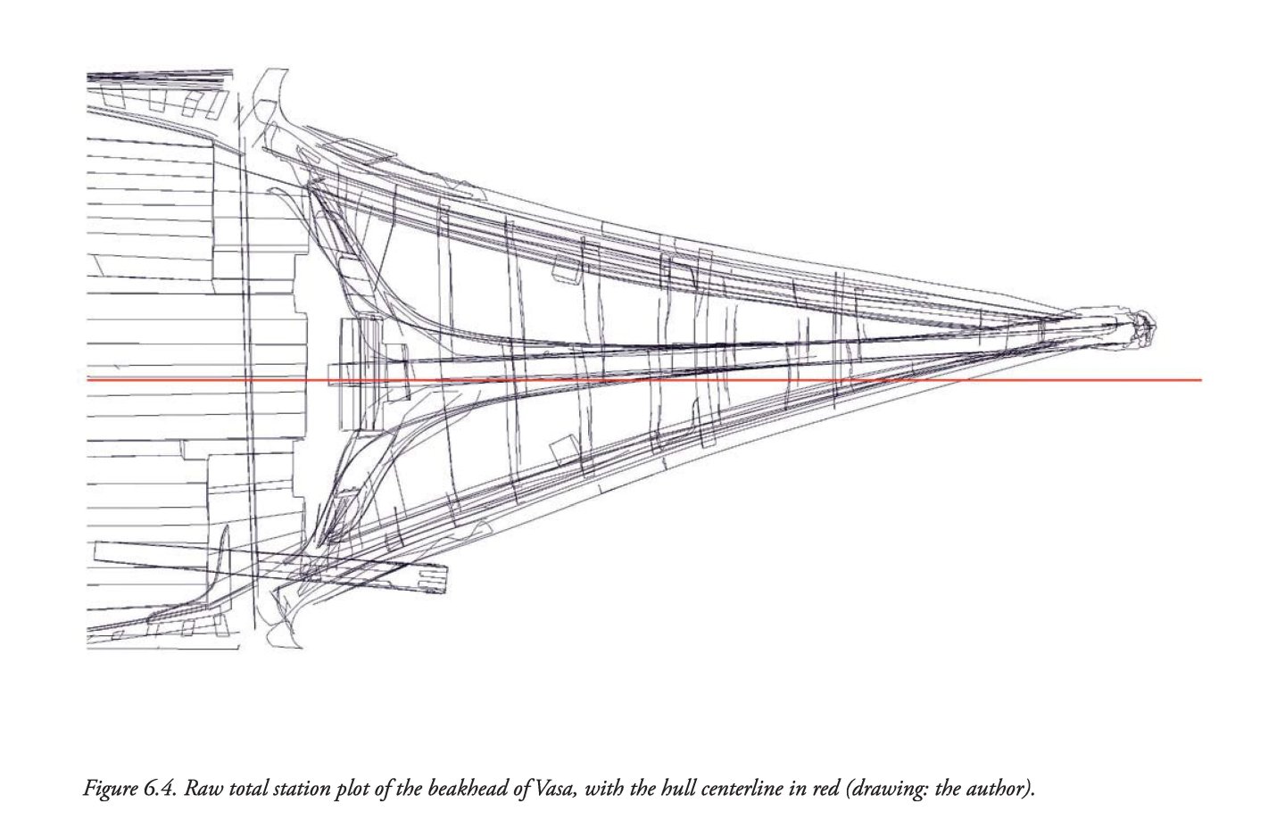
Hello E.J., In general, the flaws in the shape of the Vasa 1628 hull can be divided into two categories. The first category results from incorrect proportions, in particular the dramatically insufficient depth in hold. And in this category, there is rather nothing that can be done (corrected) when building the model. However, the second category is more subtle, because the ship was ultimately built quite sloppily in terms of geometric correctness as well. This is especially expressed in the inappropriate and at the same time irregular course of the actual maximum breadth line. As shown in the diagram below in blue dashed line. I simply have a question: are you going to ‘normalise’ the defects from this second category, or will you try to reproduce them in your model after all?

-
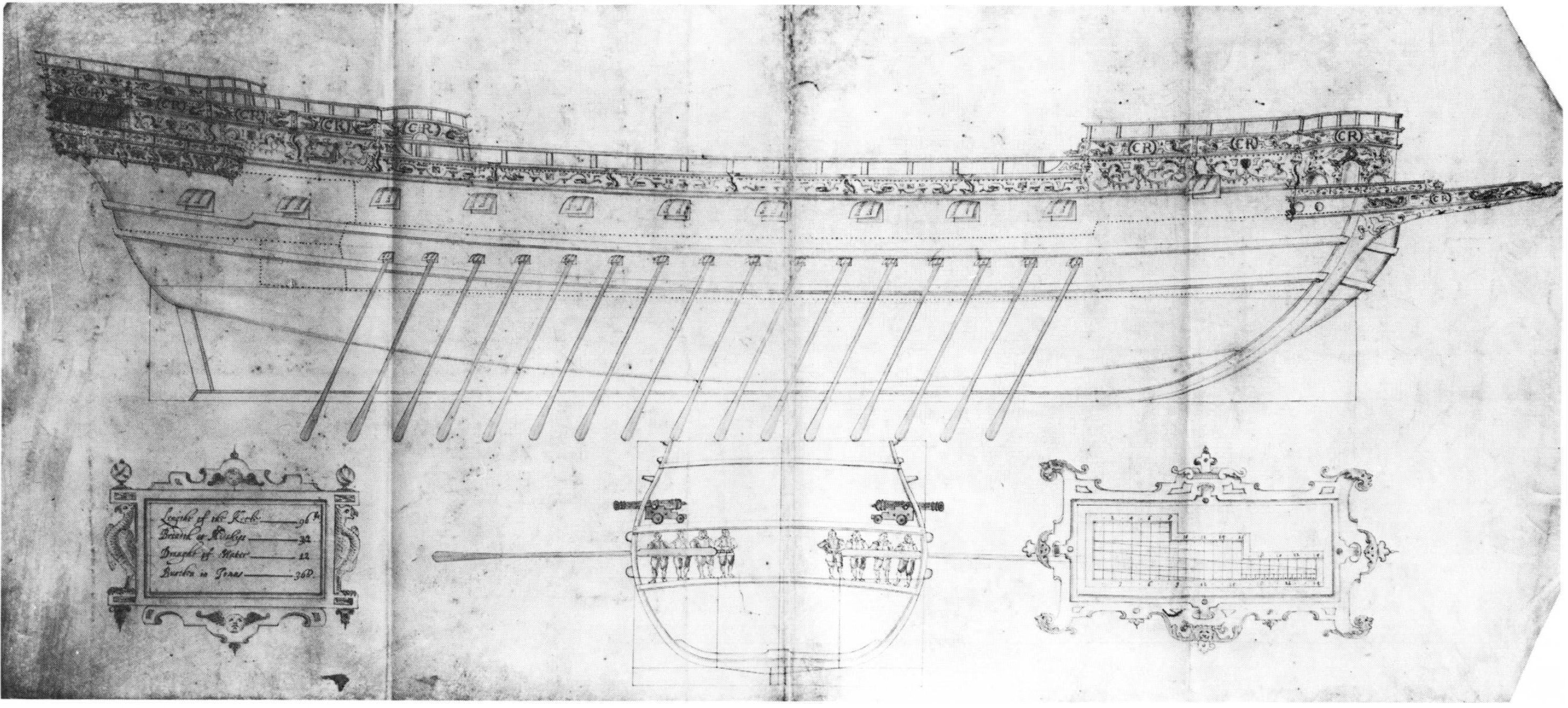
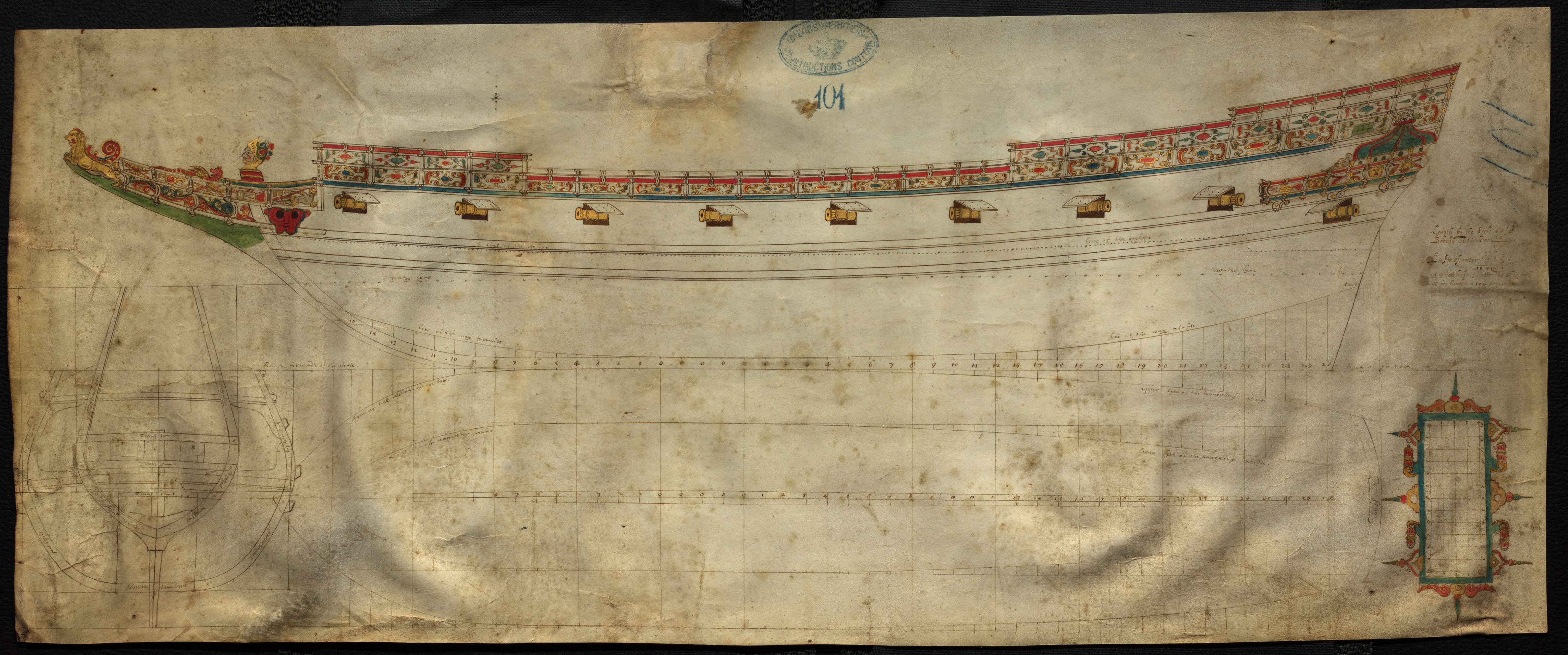
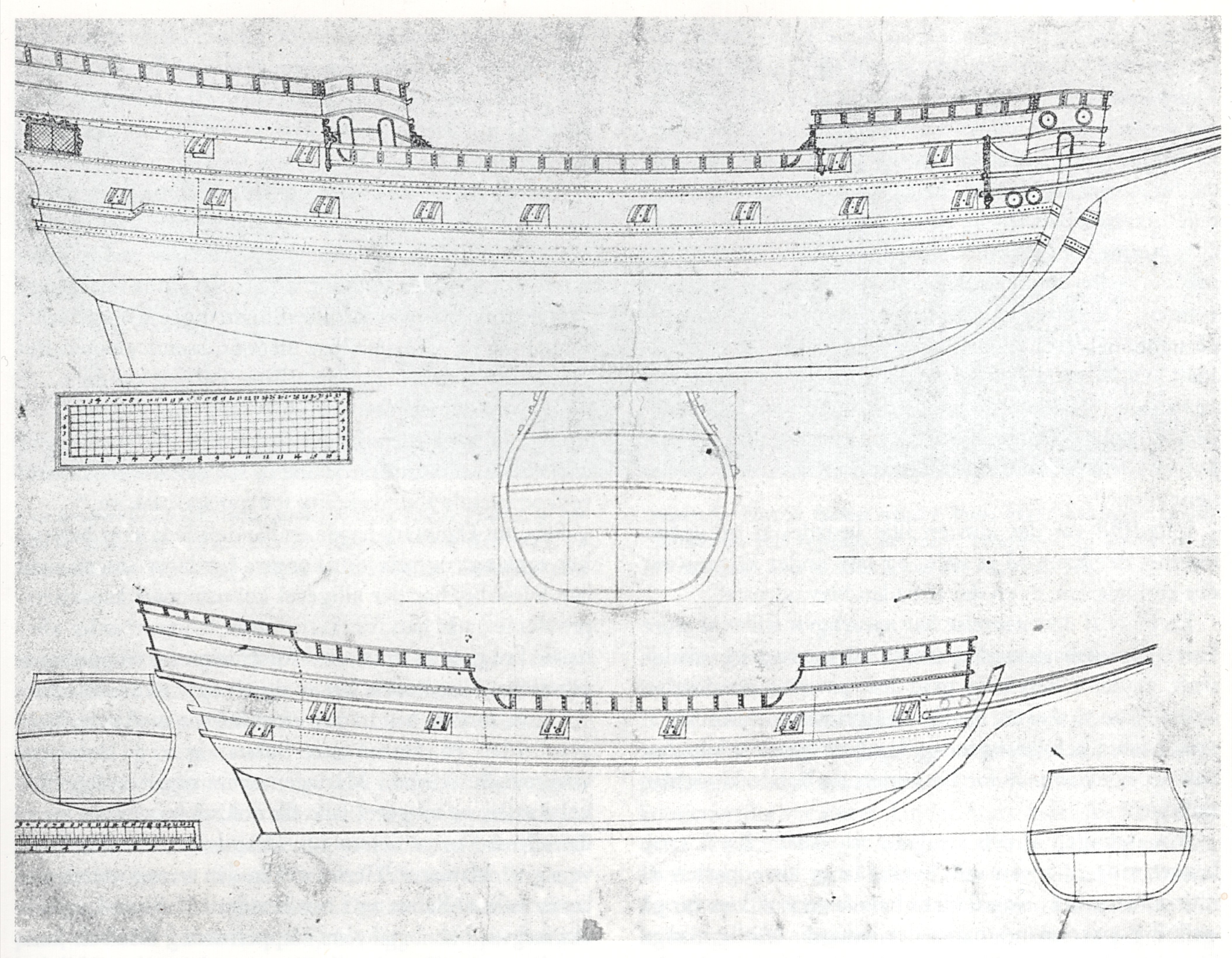
Once again, I am reviewing and analysing Dudley's vast, unpublished material and wondering how best to use, comment on and describe it. There is so much diverse information, some more important than others, that the decision on the best possible course of action is not at all obvious. In the meantime, it is worth presenting some extant designs by British (English and Scottish) designers from that period, taken from Danish and British archives, which share the same Mediterranean design paradigm as Dudley's designs — in addition to longitudinal design lines (risings and narrowings; yet no line of the greatest breadth, just ‘boca’ line instead), there is also a master frame mould. No other frames and no auxiliary design lines such as waterlines, buttock lines or diagonals. Project ca. 1600 Project ca. 1600 Project ca. 1600 Project ca. 1625 Project 1623


-
Thank you. Quite recently, I even started a thread on this very issue on a French-language forum, but before I got to the details and the heart of the matter, circumstances led me to decide to continue on one of the English-language forums. The continuation was supposed to be immediate, but somehow Mary Rose 1511 and Dudley got in the way . But that's even better, because it all ties together, so chronologically it's more advantageous. Either way, it needs to be revisited, and now I plan to do so after Dudley.
- 2,696 replies
-
- 2
-
-
- heller
- soleil royal
- (and 9 more)
-
Ah, line drawings are just a derivative; it's all about naval architecture and its evolution, the image of which is completely distorted today.
- 2,696 replies
-
- 1
-
-
- heller
- soleil royal
- (and 9 more)
-
Admittedly, structural aspects are rather secondary to me, so they are not my main focus, but criticism of various solutions adopted in these reconstructions can be found on the website http://www.gerard-delacroix.fr/. However, I have serious reservations about the design concepts used in the 17th-century reconstructions. But this is a broader topic, requiring a whole thread with explanations and examples...
-
Okay, thank you very much, I just wanted you to see it as it appears in the source iconography. And of course, you decide for yourself what to do with it. Incidentally, to be honest, I have serious issues with some aspects of Lemineur's reconstructions, and I'm not the only one. Boudriot's work is much more convincing, so to speak.
- 2,696 replies
-
- 1
-

-
- heller
- soleil royal
- (and 9 more)
-
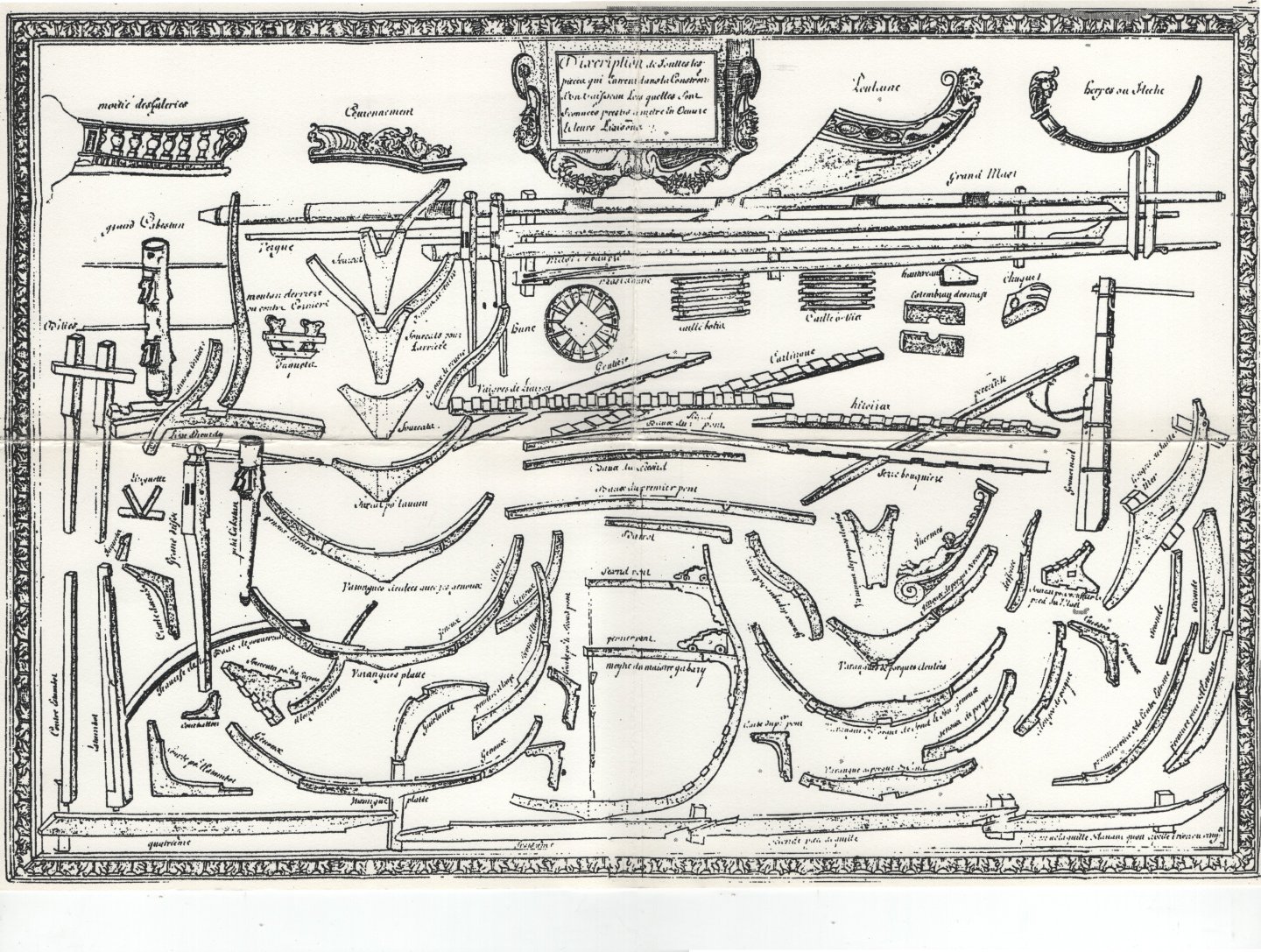
Oh, and the so-called Album de Colbert ca. 1680, how could I forget...
-(MeisterDrucke-87832).thumb.jpg.d53ecfb8024928f761912bcb3e25877d.jpg)
.thumb.jpg.b96702605207fb825638cc5e52e2e20d.jpg)
- 2,696 replies
-
- 5
-
-
-
- heller
- soleil royal
- (and 9 more)
-
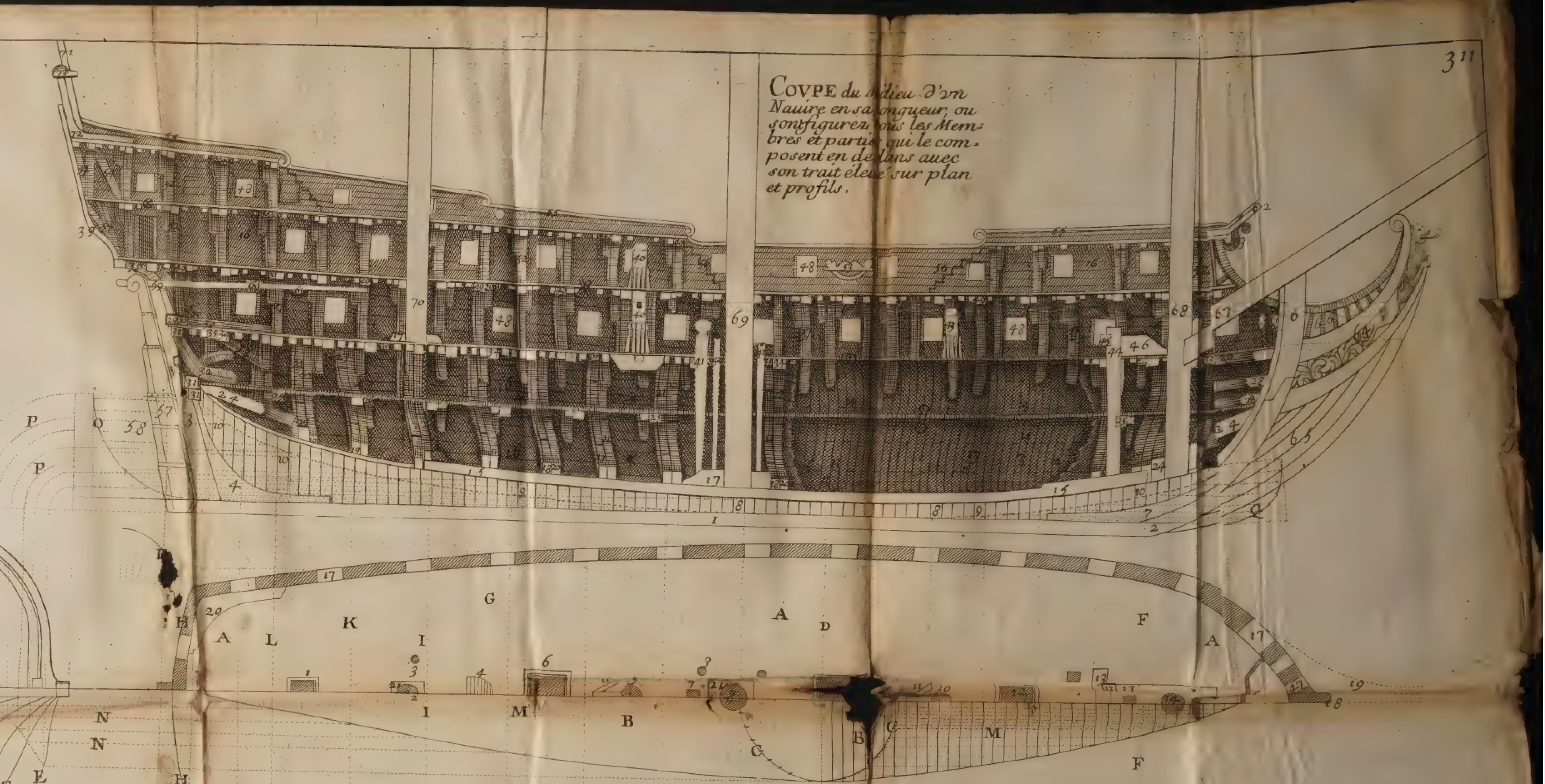
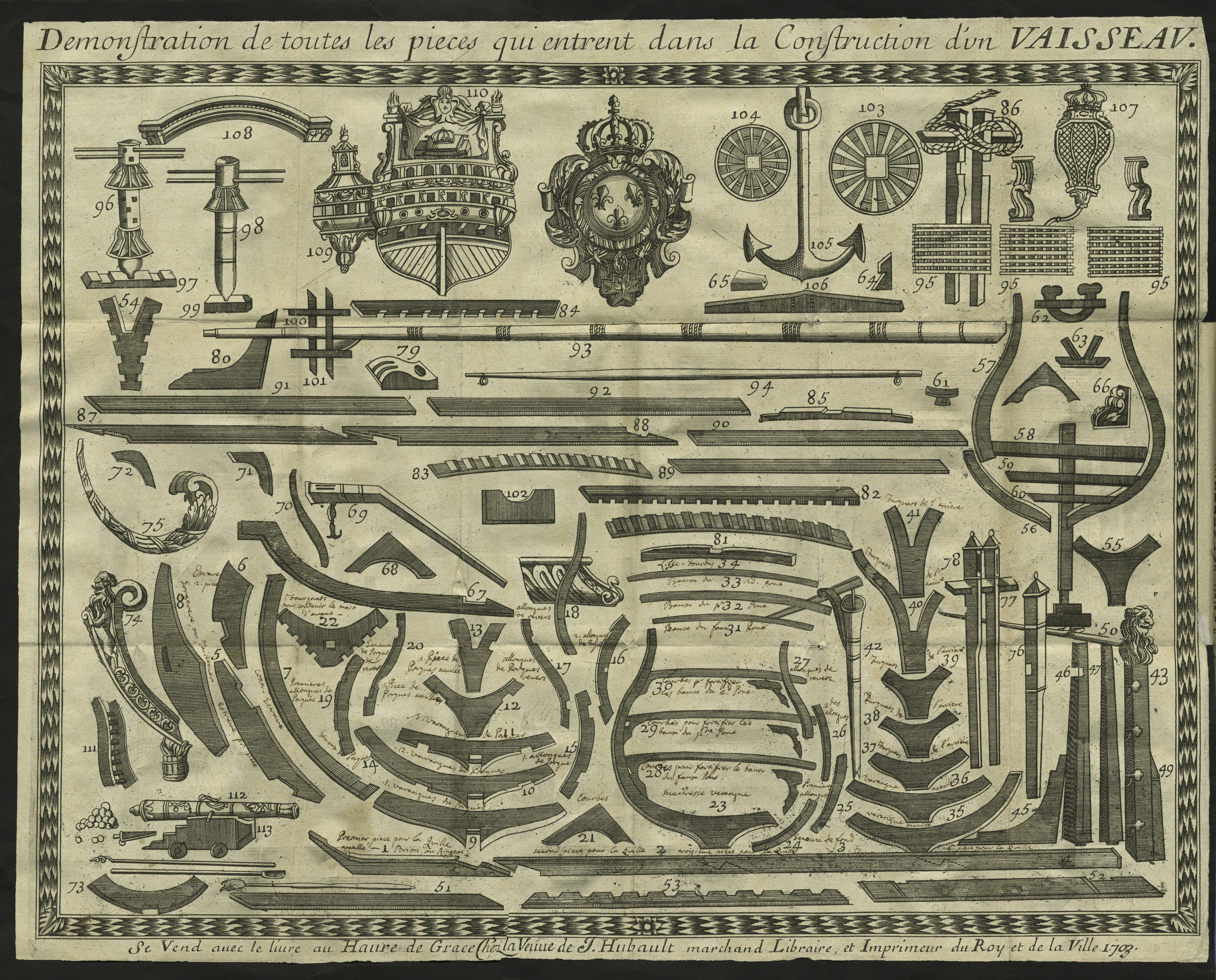
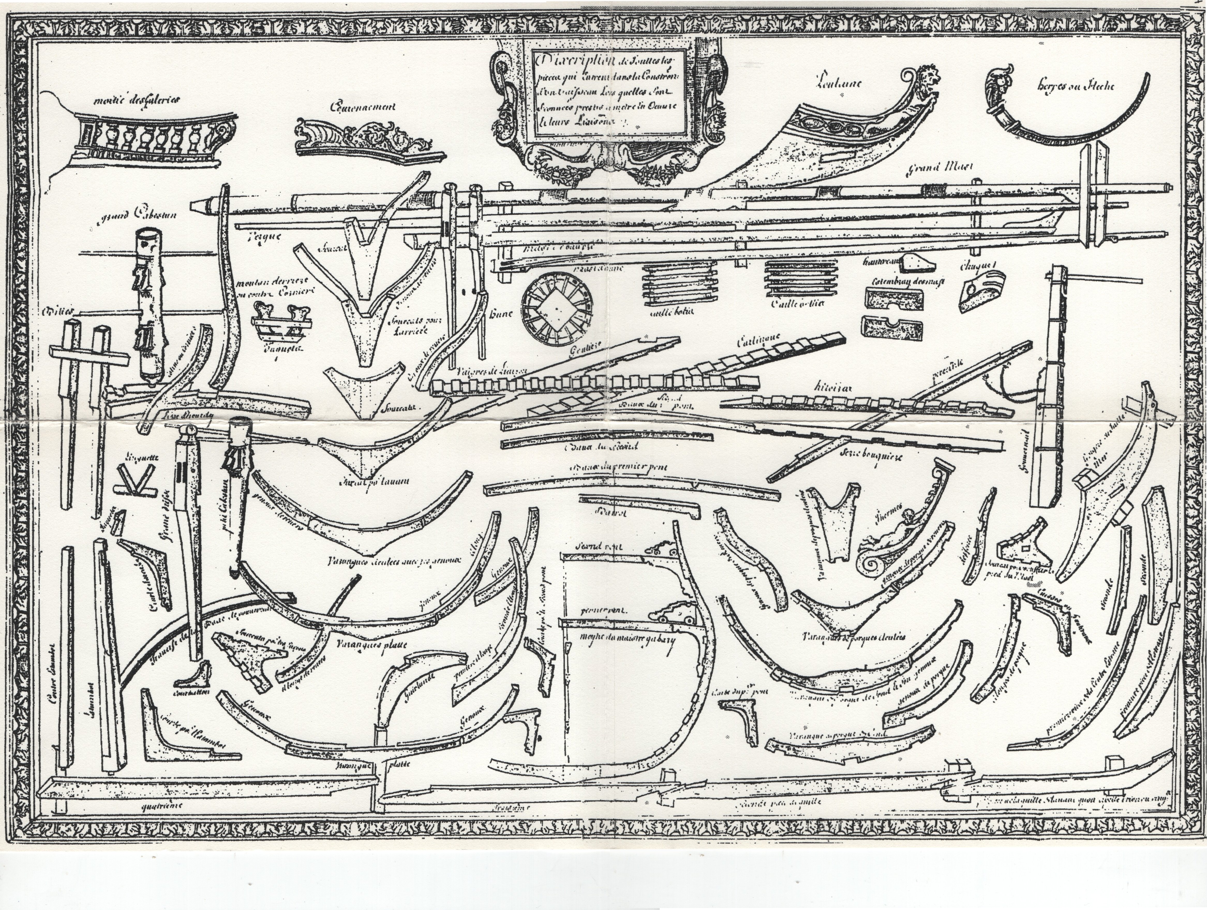
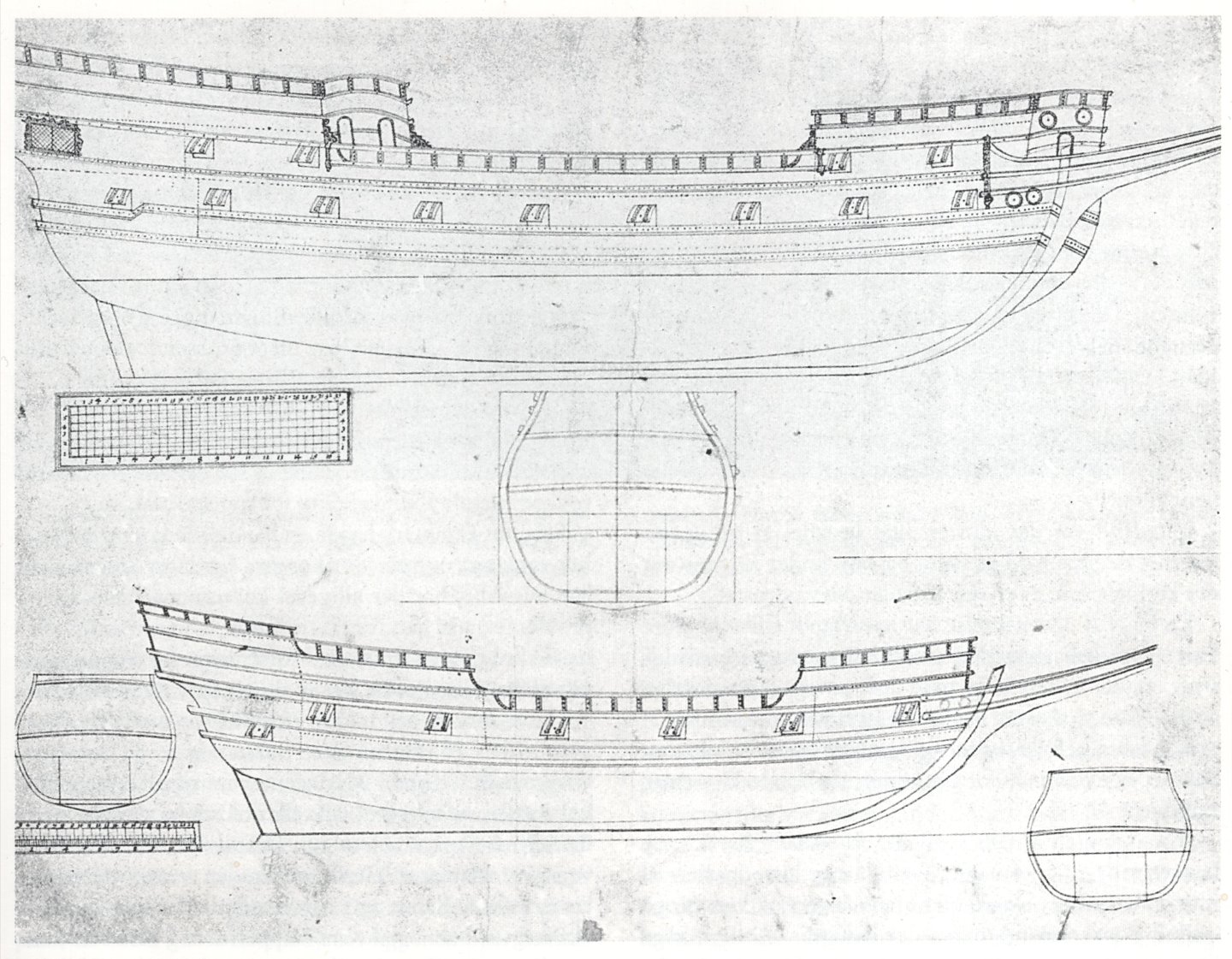
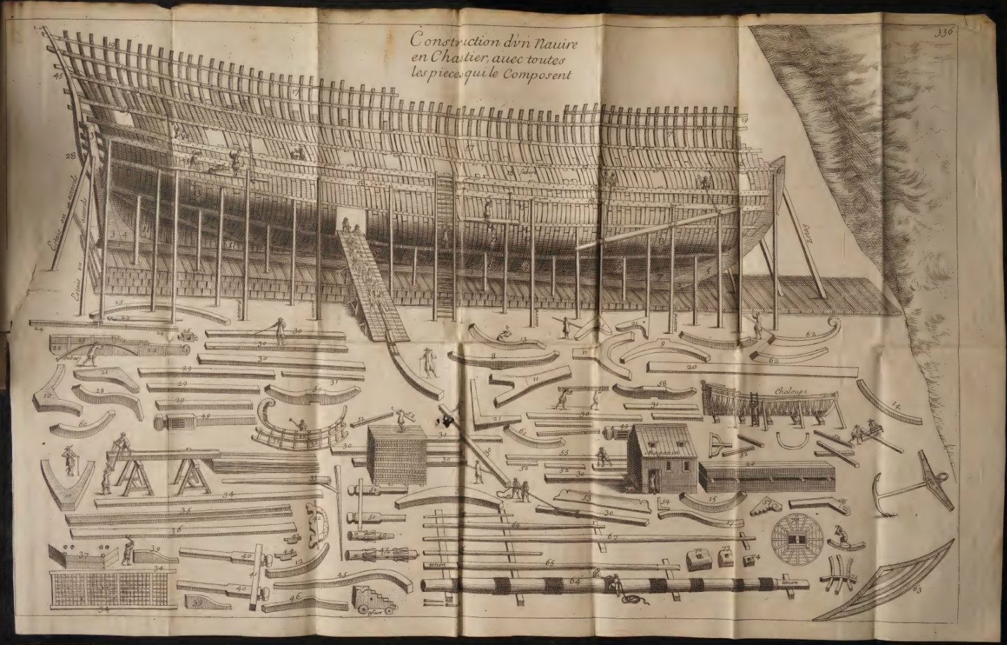
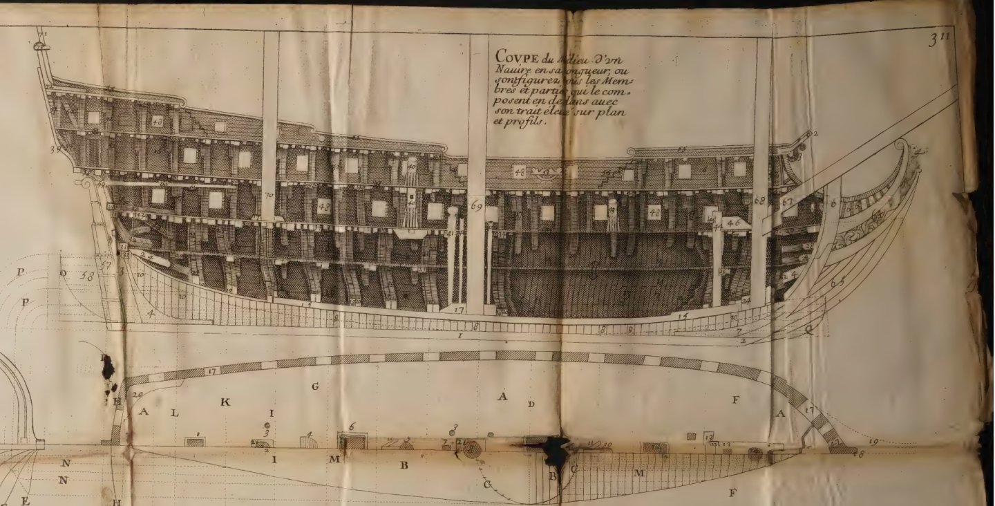
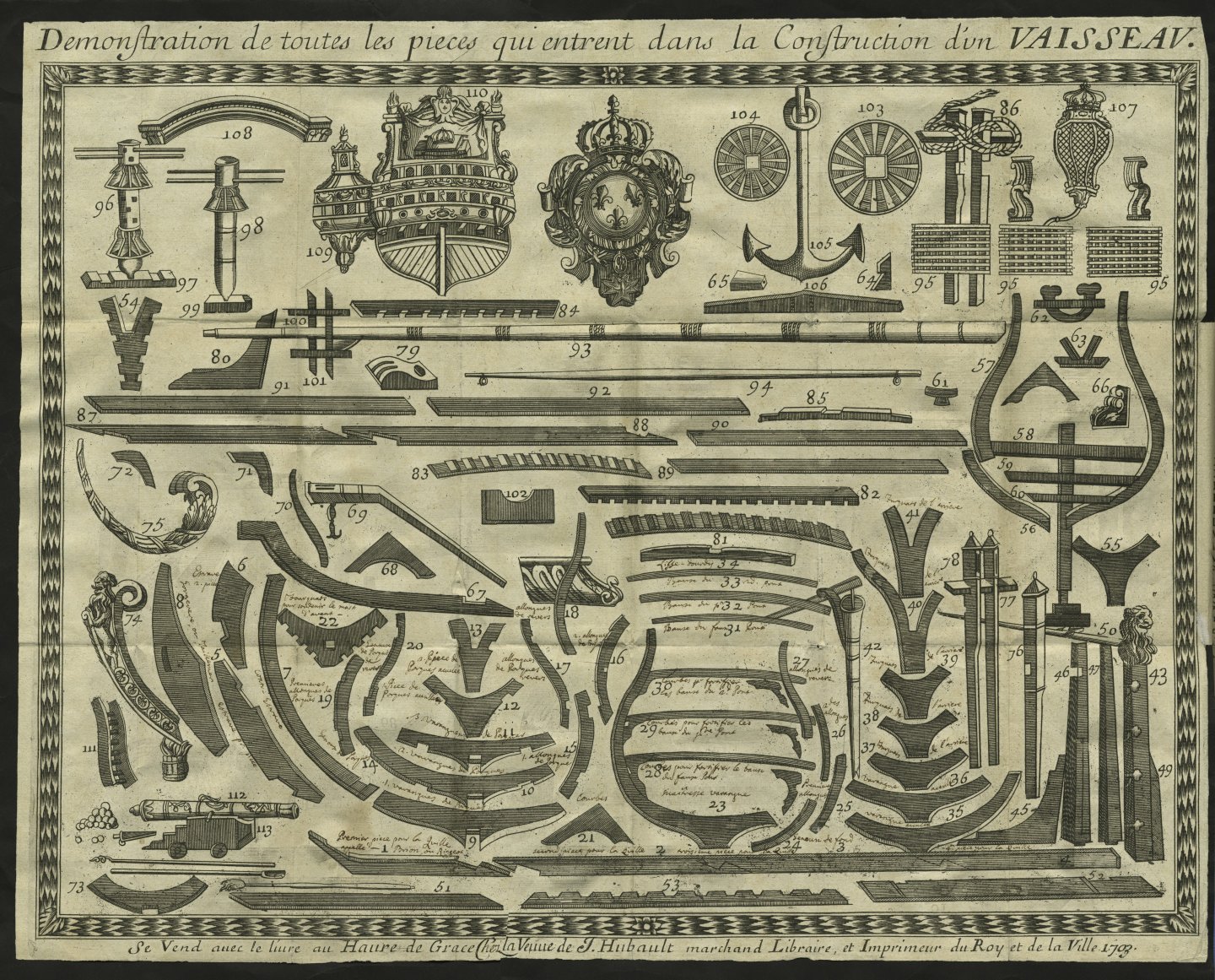
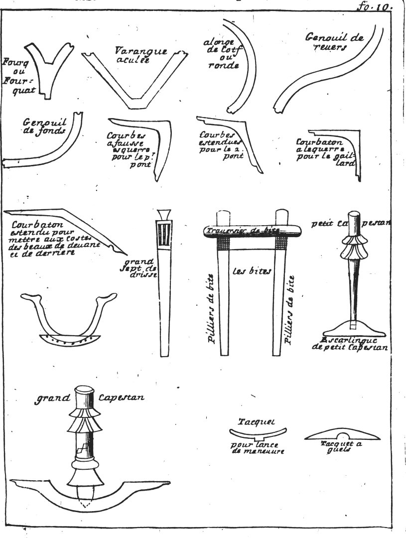
Hi Marc, Very nice, but why did you make an 18th-century capstan, especially since you are putting so much effort into this project? As the capstan may be considered quite an iconic element of a ship, I thought you might like to see some graphics from that era. Admittedly, they are a bit schematic, but still they show the type of capstan used in that period and in that place. Actually both capstans, that is main (double) capstan and small (single) one. Claude Caron, Traité des bois servans à tous usages, 1676: anon., Construction des Vaisseaux du Roy, Havre de Grace 1691: F. Dassié, L'architecture navale, Paris 1677: François Coulomb, Livre de construction des vaisseaux, 1683:
- 2,696 replies
-
- 4
-
-
-
- heller
- soleil royal
- (and 9 more)


-(MeisterDrucke-87832).jpg.ed3d91b49c3cb3ec8ef126c800116f1b.jpg)
.jpg.5bfa3537dc76396c5b1bb4f1d5a578b5.jpg)