.jpg.6c90d67e7e9071af590f4d4a2a8bc908.jpg)
Waldemar
-
Posts
1,003 -
Joined
Content Type
Profiles
Forums
Gallery
Events
Everything posted by Waldemar
-
.thumb.jpg.c6343966b029e7941df5b987d129aac6.jpg) Yes, this is very good museum practice. You can immediately see which parts are original and which are modern replacements. There is also another school of thought, quite the opposite, which prefers that the replaced elements be indistinguishable from the original ones next to them.
Yes, this is very good museum practice. You can immediately see which parts are original and which are modern replacements. There is also another school of thought, quite the opposite, which prefers that the replaced elements be indistinguishable from the original ones next to them. -
Review Le Coureur 1776 - Shipyard 1:72-scale Laser-Cut Card Model Kit
Waldemar replied to catopower's topic in REVIEWS: Model kits
There is another explanation, even more likely. The differences in the hull shapes on both plans from that era are due to the fact that although the British were able to measure the hulls of the captured vessels very accurately, already when drawing up their plans, they were, in a sense, designing such vessels from scratch, but using different design methods, which inevitably altered the actual shapes of the hulls to a greater or lesser extent. Not to mention the natural deformations of the hull during the ship's use. This is why today's French researchers consistently reject the lines from such plans of captured ships, preferring instead the original plans by the French designers (if, of course, they have a choice). And rightly so, and this is the first exception to this rule that I am aware of. For the above reasons, the original French design plan should be considered more reliable in terms of the shape of the hull, rather than an approximation made after the ship's capture using other design techniques that are incompatible with the original ones.- 12 replies
-
- 3
-

-
- Le Coureur
- Shipyard
- (and 1 more)
-
Either way, from what you have just shown, there is still a lot of dubbing to be done on normal frames. Just like in real-scale construction!
- 139 replies
-
- 3
-
-
- ancre
- Bateau de Lanveoc
- (and 2 more)
-
Hi Jacques, I've been following your thread and I can see that lately it's been an unnecessary road through frustration leading to disappointment . If I may suggest, shape the surfaces of both ends of the hull in the same way as the original builders did. Start by removing the cant frames (although one pair at the stern may still prove useful, choose one of them in this case). Prepare and attach 5 or 6 ribbands/battens per side. Keep an eye on symmetry, especially at the ends of the hull, but a slight asymmetry will not be the end of the world, just as it was not in real vessels. Only then shape and secure the cant frames, guided by the battens, preferably using temporary paper templates. Alternatively, instead of battens, you can try normally planking the hull right away, and only then shape and attach the cant frames, already more to reinforce the structure than to shape the surface. What do you think?
- 139 replies
-
- 2
-
-
- ancre
- Bateau de Lanveoc
- (and 2 more)
-
Intentional skewing of the bowsprit and beakhead seems rather unlikely, as the bowsprit runs exactly over the stempost (unlike, for example, English designs of the period, where the bowsprit ran alongside the stempost, always or at least often) and there was no reason to angle them in the horizontal plane. This arrangement is particularly evident in Björn Landström's fantastic illustrations in his equally fantastic book The Royal Warship Vasa, published in 1988. I highly recommend consulting this publication as well.
-
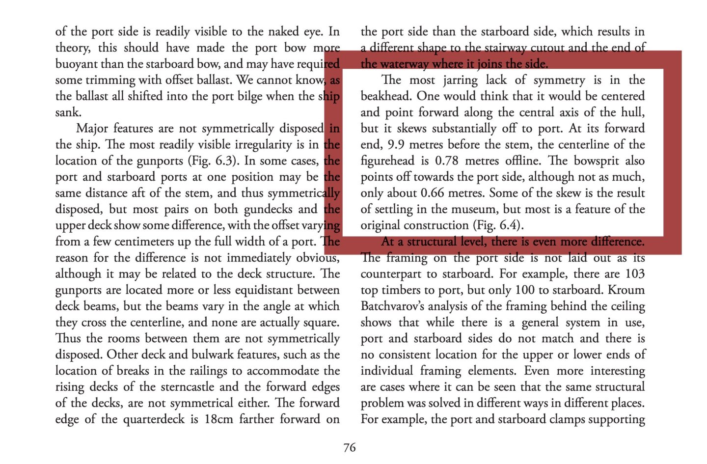
In this particular case, as in many others, I suggest taking a look at the relevant commentary in the article referred to. The entire section on the various asymmetries of the Vasa's structure is both interesting and informative, and here are a few paragraphs, including the one on the beakhead:
-
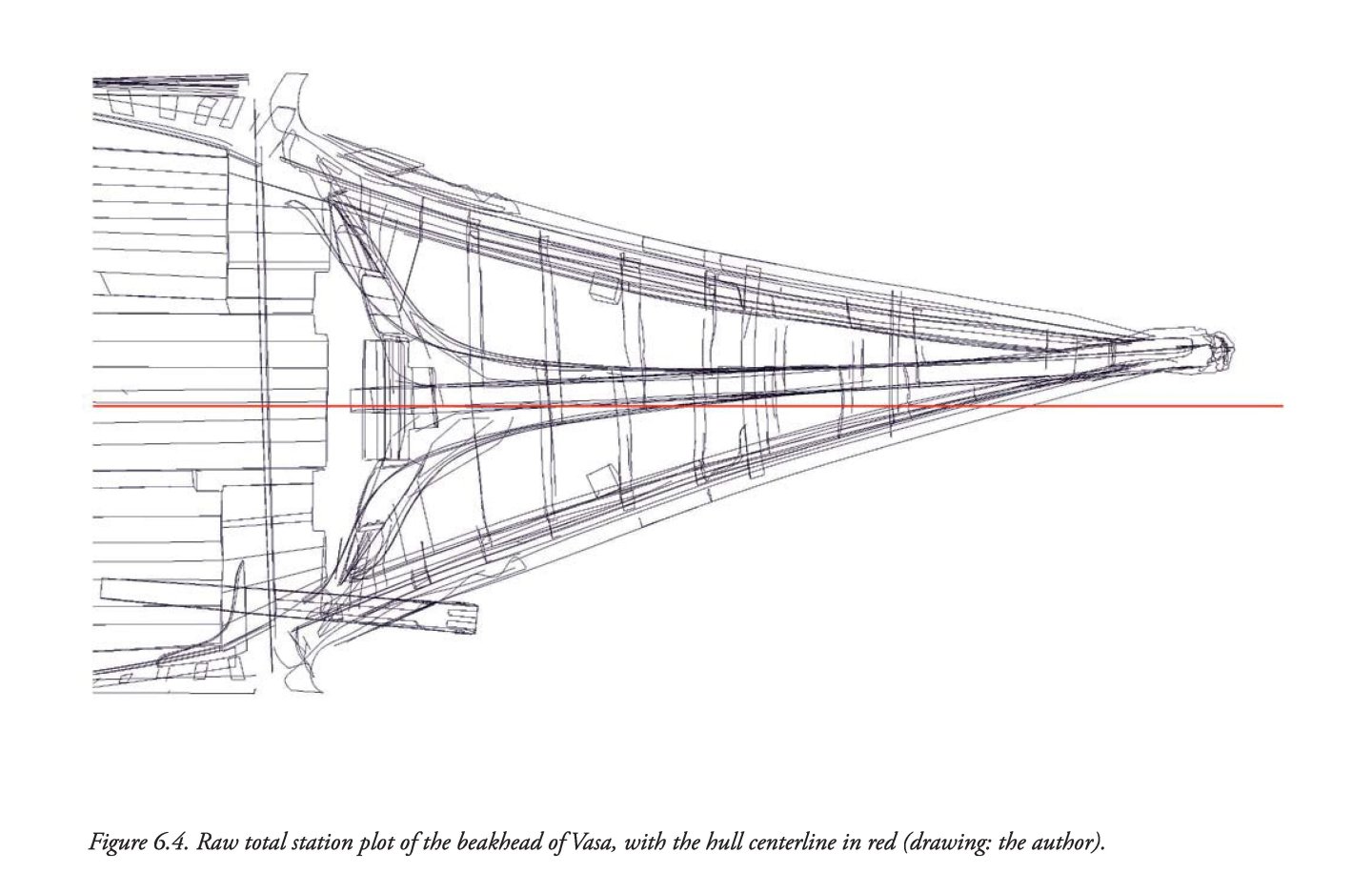
This will probably be the first model of the Vasa 1628 that I know of that will (intentionally) incorporate all the known defects and flaws of this vessel. I am particularly curious to see how the distortion of the beakhead will look in the photos of the model. It can be said that this rather conspicuous feature is never reproduced by model makers, so I commend the courage to do so. Not everyone may know what this is about, so below is an illustration showing the beakhead distortion as it appears on the original (from a paper by Fred Hocker, In Details Remembered. Interpreting the Human Component in Shipbuilding, 2013). In fact, this very feature was omitted even in the official plans of the ship published in 1980, and there is still no updated set of plans.
-
As for your fundamental decision to build a model with all the flaws of the original, I actually agree with it and it would probably be my choice as well. I think I would even make a crooked beakhead like in the original, instead of a straight one. On the other hand, my diagnosis of the causes of these errors would be different. For example, it is known that the chief designer's successor realised during construction that the design was flawed and tried to remedy it, but unsuccessfully, and even these ‘rescue’ attempts introduced further errors with disastrous consequences. As it happens, other designers and builders at that time did not normally make these mistakes.
-
Hello E.J., In general, the flaws in the shape of the Vasa 1628 hull can be divided into two categories. The first category results from incorrect proportions, in particular the dramatically insufficient depth in hold. And in this category, there is rather nothing that can be done (corrected) when building the model. However, the second category is more subtle, because the ship was ultimately built quite sloppily in terms of geometric correctness as well. This is especially expressed in the inappropriate and at the same time irregular course of the actual maximum breadth line. As shown in the diagram below in blue dashed line. I simply have a question: are you going to ‘normalise’ the defects from this second category, or will you try to reproduce them in your model after all?

-
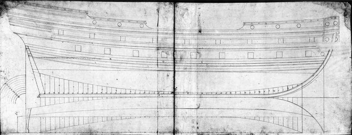
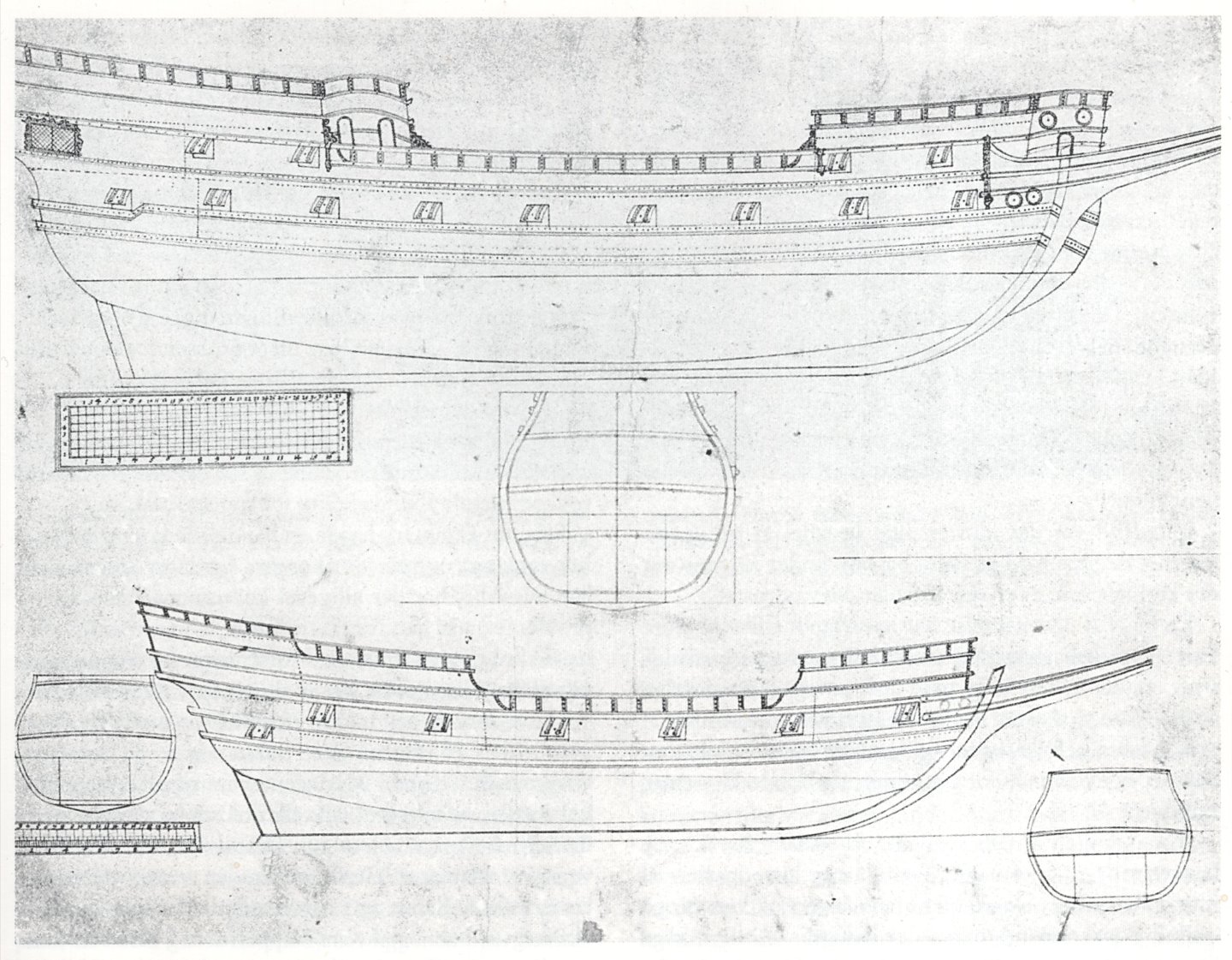
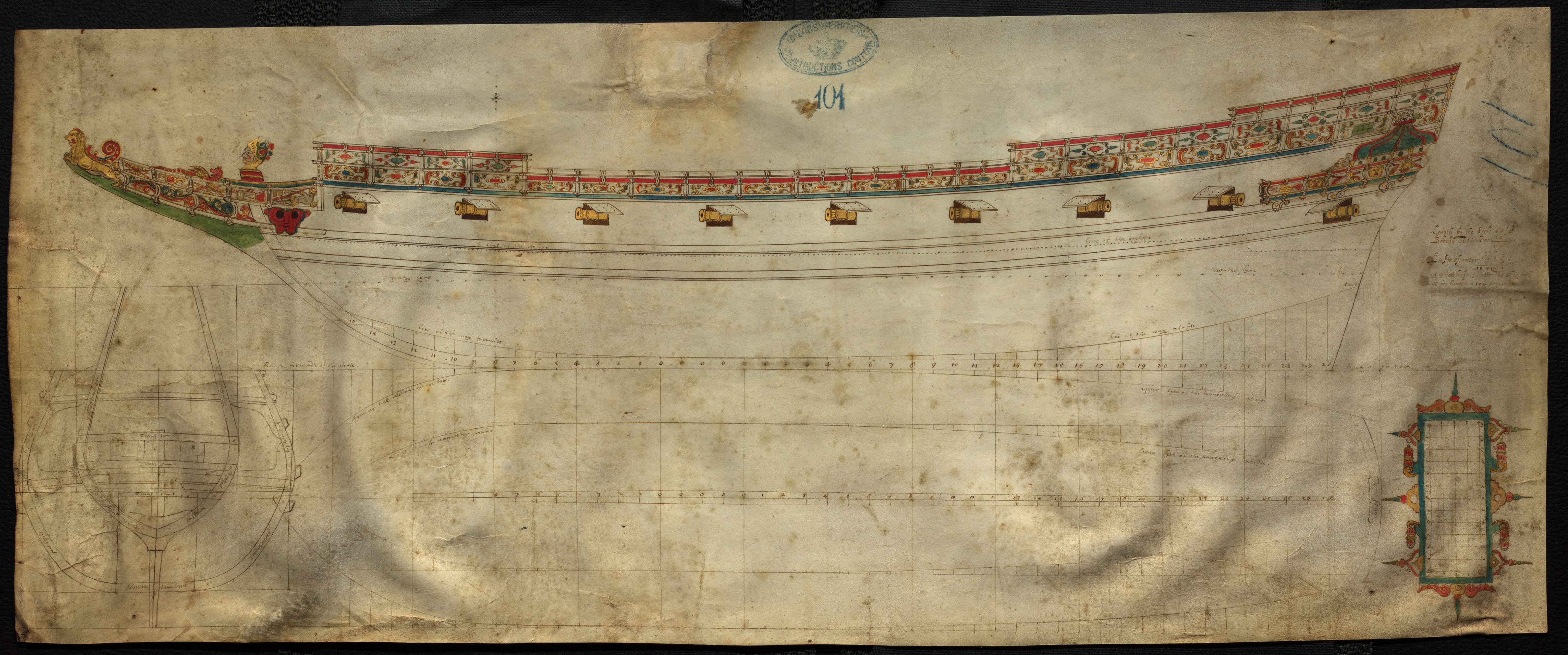
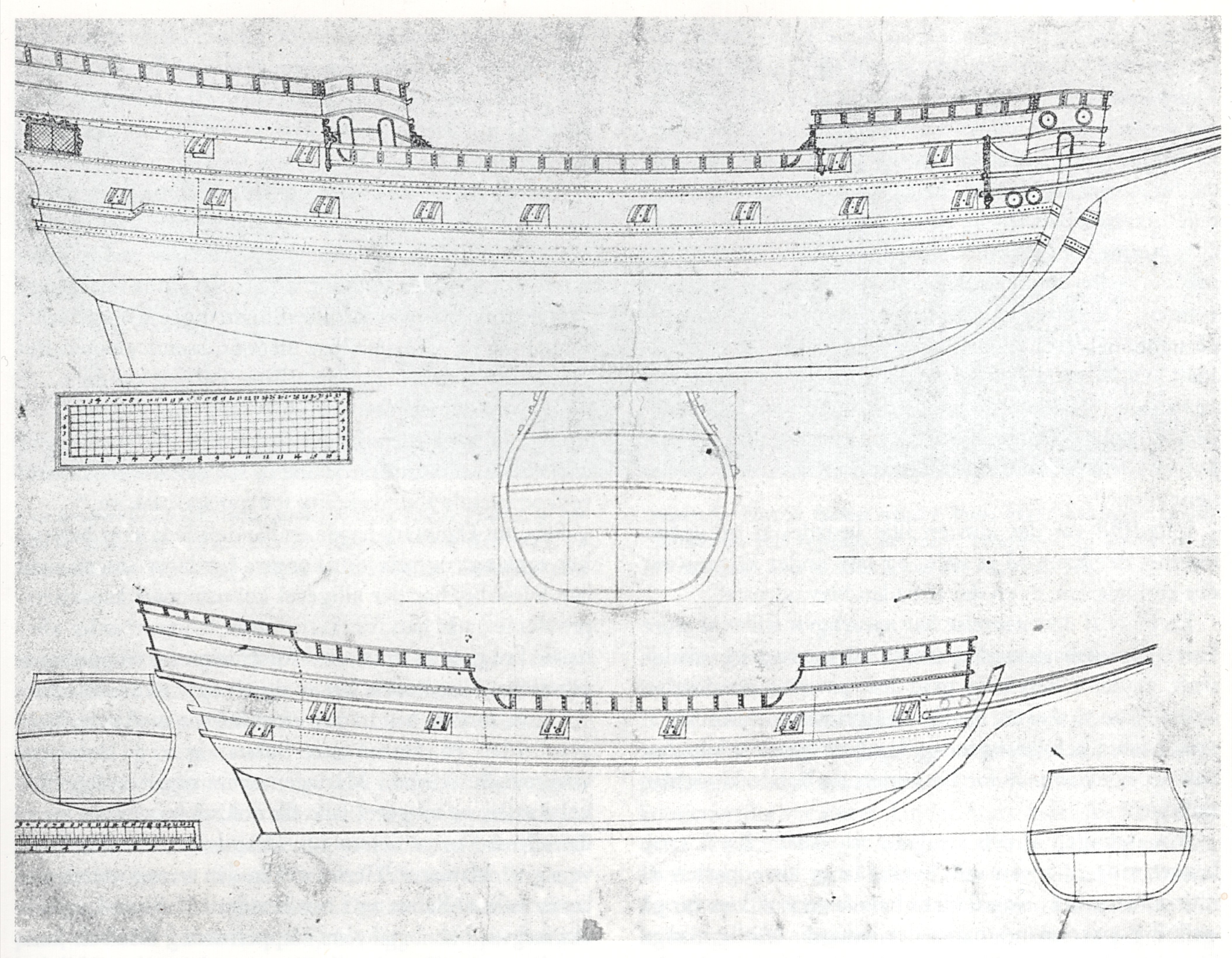
Once again, I am reviewing and analysing Dudley's vast, unpublished material and wondering how best to use, comment on and describe it. There is so much diverse information, some more important than others, that the decision on the best possible course of action is not at all obvious. In the meantime, it is worth presenting some extant designs by British (English and Scottish) designers from that period, taken from Danish and British archives, which share the same Mediterranean design paradigm as Dudley's designs — in addition to longitudinal design lines (risings and narrowings; yet no line of the greatest breadth, just ‘boca’ line instead), there is also a master frame mould. No other frames and no auxiliary design lines such as waterlines, buttock lines or diagonals. Project ca. 1600 Project ca. 1600 Project ca. 1600 Project ca. 1625 Project 1623


-
Thank you. Quite recently, I even started a thread on this very issue on a French-language forum, but before I got to the details and the heart of the matter, circumstances led me to decide to continue on one of the English-language forums. The continuation was supposed to be immediate, but somehow Mary Rose 1511 and Dudley got in the way . But that's even better, because it all ties together, so chronologically it's more advantageous. Either way, it needs to be revisited, and now I plan to do so after Dudley.
- 2,699 replies
-
- 2
-
-
- heller
- soleil royal
- (and 9 more)
-
Ah, line drawings are just a derivative; it's all about naval architecture and its evolution, the image of which is completely distorted today.
- 2,699 replies
-
- 1
-
-
- heller
- soleil royal
- (and 9 more)
-
Admittedly, structural aspects are rather secondary to me, so they are not my main focus, but criticism of various solutions adopted in these reconstructions can be found on the website http://www.gerard-delacroix.fr/. However, I have serious reservations about the design concepts used in the 17th-century reconstructions. But this is a broader topic, requiring a whole thread with explanations and examples...
-
Okay, thank you very much, I just wanted you to see it as it appears in the source iconography. And of course, you decide for yourself what to do with it. Incidentally, to be honest, I have serious issues with some aspects of Lemineur's reconstructions, and I'm not the only one. Boudriot's work is much more convincing, so to speak.
- 2,699 replies
-
- 1
-

-
- heller
- soleil royal
- (and 9 more)
-
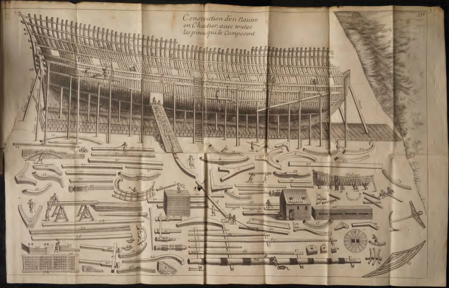
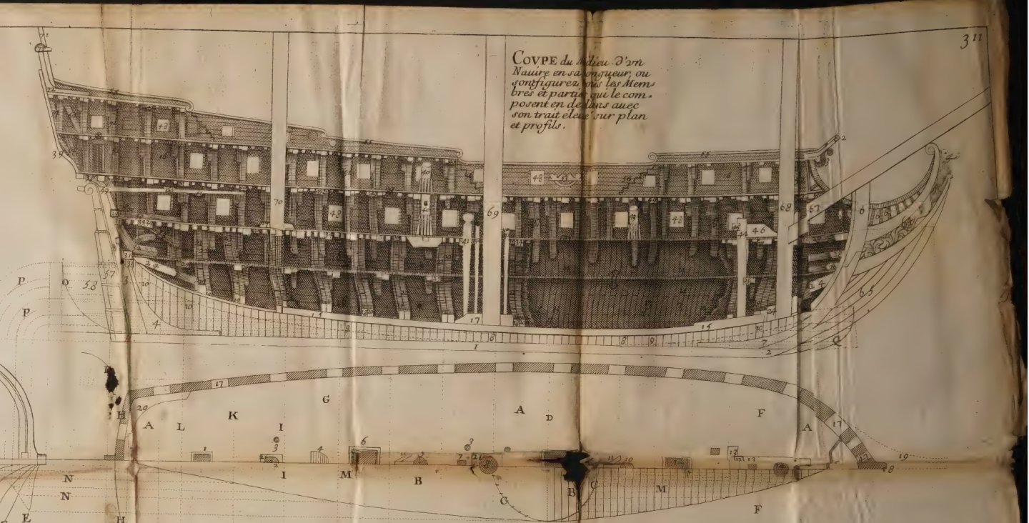
Oh, and the so-called Album de Colbert ca. 1680, how could I forget...
-(MeisterDrucke-87832).thumb.jpg.d53ecfb8024928f761912bcb3e25877d.jpg)
.thumb.jpg.b96702605207fb825638cc5e52e2e20d.jpg)
- 2,699 replies
-
- 5
-
-
-
- heller
- soleil royal
- (and 9 more)
-
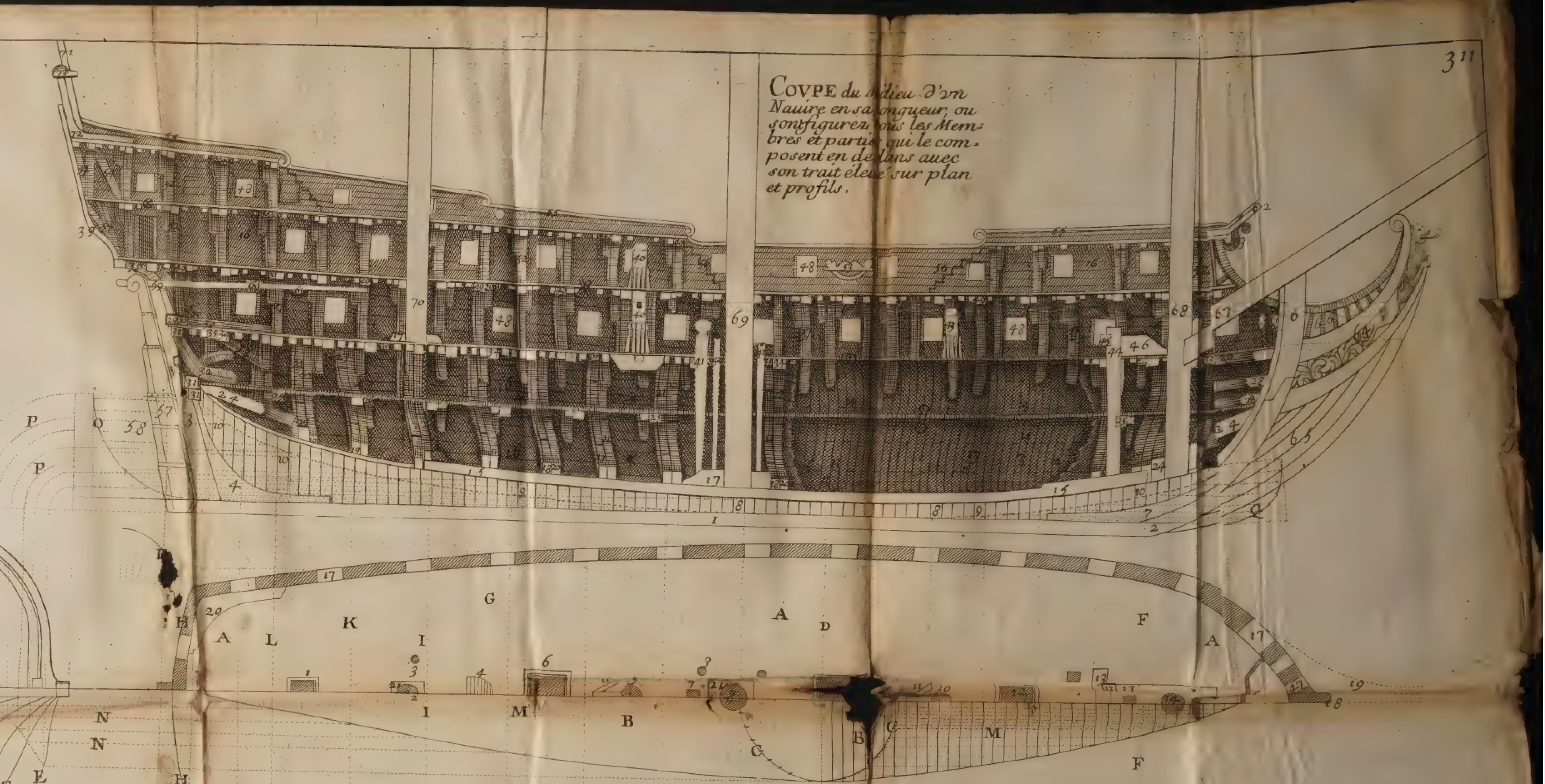
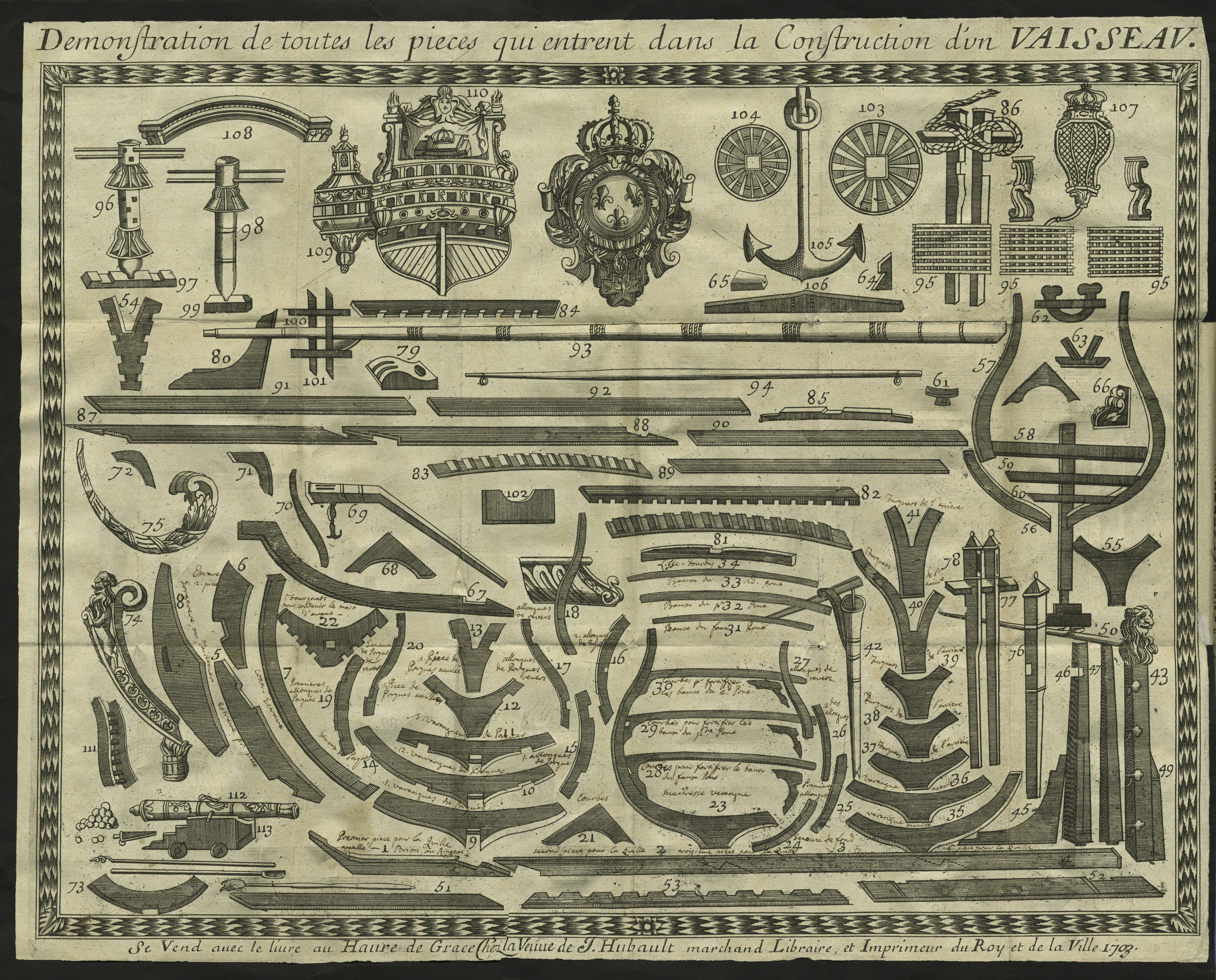
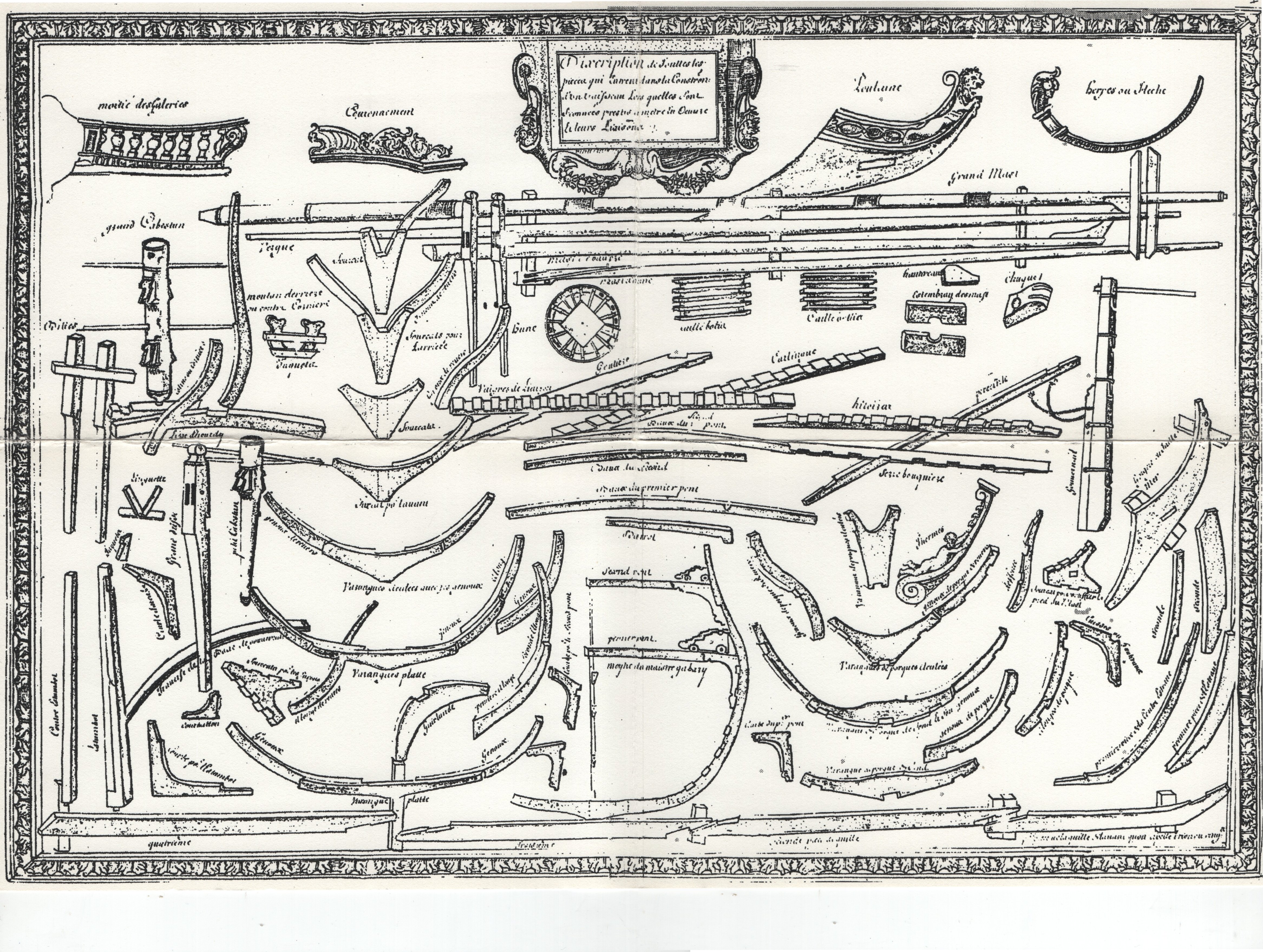
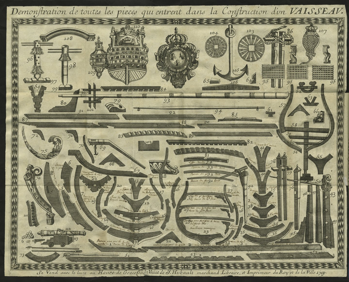
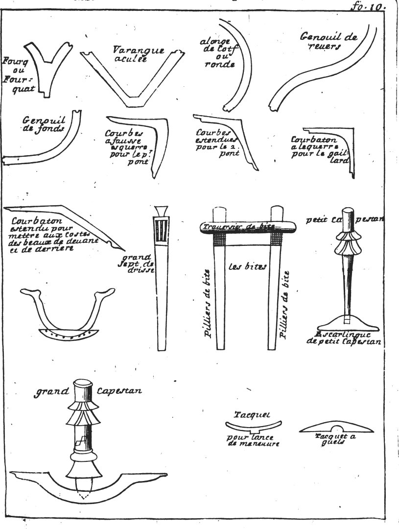
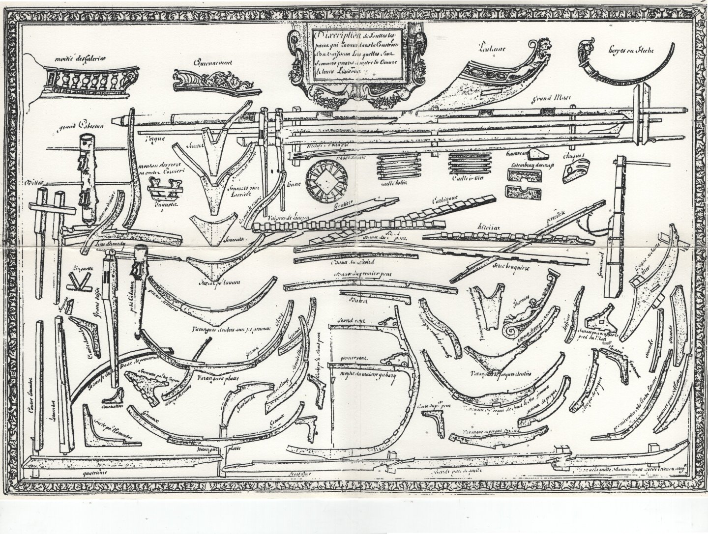
Hi Marc, Very nice, but why did you make an 18th-century capstan, especially since you are putting so much effort into this project? As the capstan may be considered quite an iconic element of a ship, I thought you might like to see some graphics from that era. Admittedly, they are a bit schematic, but still they show the type of capstan used in that period and in that place. Actually both capstans, that is main (double) capstan and small (single) one. Claude Caron, Traité des bois servans à tous usages, 1676: anon., Construction des Vaisseaux du Roy, Havre de Grace 1691: F. Dassié, L'architecture navale, Paris 1677: François Coulomb, Livre de construction des vaisseaux, 1683:
- 2,699 replies
-
- 4
-
-
-
- heller
- soleil royal
- (and 9 more)
-
ON CERTAIN INVENTIONS OF THE AUTHOR to be applied with his seven previous designs. Chapter XVI. The author has made use of some of his own inventions to perfect preceding designs, particularly square-rigged vessels, but also galeroni and galerate, for rowing; which inventions can be useful in many necessary occasions, and it certainly can't hurt to know them; provided they can be put into practice where and when expedient, and not otherwise out of necessity. For the first invention, it should be noted that the designs already produced are for vessels that are longer than usual, in order (for their speed) to always fight from windward on the high seas, and with greater force, as well as to hold up well and to sail much better than others, thanks to their shallow draught and their length. It commonly follows that these types of square-rigged vessels have a tendency to lean with the transverse wind when sailing close-hauled, somewhat more so than shorter vessels with a greater draught; in any case, the author has sought, through extensive experimentation, to compensate for this shortcoming by means of a keel of his own invention, which is deeper than usual and slightly concave; combined, however, with the false keel of the first preceding design; and by means of this, the aforementioned defect, although minor, will not only be remedied perfectly, but will also make them more stable when sailing close-hauled than all other vessels. This invention was applied, with good success, to the galizabra S. Cosimo, & to the galeratina of the same name, of the third and sixth design, & to other vessels of the Author. The second invention, also tried and tested by the author, is a passageway with two-and-a-half-inch thick caulked fir boards, which can be build around the inside of the ship's hold; and connected from under to the first deck, it will be four feet high and three feet wide at the top, and the passageway will be partitioned into six small rooms on each side, similarly caulked, with a small door for each one, above in the deck, so that during combat, if by chance any enemy cannonballs pass under the water, the hole can be immediately plugged, so that the vessel does not risk sinking due to the enemy's shots; and this invention can be better understood from the figure of the first design, letter G, to be applied to the four designs of the preceding square ships; & it is an invention tried and tested in two ships built for the Most Serene Grand Dukes Ferdinand I and Cosimo II, namely the S. Giovanni Battista, of the second design, and the San Cosimo, of the third. However, it should be noted that this invention is suitable for warships on short voyages, otherwise on long voyages to India, the said passageway would prevent the ship's hold from carrying sufficient provisions for the voyage. The third invention can be applied well, according to the test carried out, to the fourth design of frigate with a light deck (i.e. spardeck) above the first, which is gridded halfway across the width and woven in the form of double squares, so that one can walk freely on it; but by turning those squares along the sides of the said light deck, no one can stand on them, by virtue of certain long, sharp steel nails, thus preventing the enemy from boarding the ship when it is in port; since on the high seas there is no such danger against square-rigged vessels; this was done in the galizabra S. Cosimo made by the Author for the Most Serene Grand Duke Cosimo II. The fourth invention is that the rudder of the vessel should be slightly concave on the side where it touches the water, because this will make it easier for long vessels to steer and navigate well, especially when sailing close-hauled, and down wind, as needed. This was also done on the rudder of the aforementioned galizabra San Cosimo. The fifth invention can be seen in the figure of the mould of the fourth design of a frigate, with a low passageway in the middle of the deck, to strengthen the length of the vessel and ensure its safety at sea; this also yields other benefits that are very useful in combat; this was done in the galizabra S. Cosimo and in a pinnace made by the author in Livorno. The sixth invention is that the pumps of the author's square-rigged vessels are fitted with iron chains, in the manner of the royal rowbarges of England, because they are more reliable and, when necessary, expel a much greater quantity of water which has entered the vessel. The seventh is that the pillars supporting the decks in the preceding designs are sloped, according to the figures in the said designs, and not straight as usual; because these, being straight in the usual manner, are much weaker in supporting artillery and other heavy weights; and it is a very useful invention for warships, because in this way the weight of the artillery will rest on the keel of the ship and strengthen it, so that it will not be weakened so much by the fortunes of the sea; this was done in the galizabra S.Cosimo, of the third design. The eighth invention is that the bulwarks of the author's ships for combat must be made of canvas sewn with old ropes on the inside, to be musket-proof; because if they were made of wood as usual, they would impede the movement of the ship too much, due to the dead weight, especially in rowing ships; besides, the cannonballs that pass through wooden bulwarks kill many more people by splinters and broken wood than they do with the ball itself; This is remedied by the aforementioned canvas bulwarks, in pieces that can be kept in the hold when not in combat; and therefore this invention is of great importance for combat at sea, especially for galleys and galleasses in the fleet; and so it was also done in the galerata of the sixth design. The ninth invention is that the galerata must carry a net that does not impede rowing or sailing, and which can be raised like a tent, but not too high, to better defend the vessel in battle, so that it cannot be boarded by the enemy without great disadvantage; this net will be raised when fighting, and then can be stored in the hold. There are other inventions, tried and tested by the author himself, which are of lesser importance and are omitted for the sake of brevity, especially since the best of them can still be seen in the preceding figures of warships. With this advice, the second volume of The Mysteries comes to an end. translation: Waldemar Gurgul
-
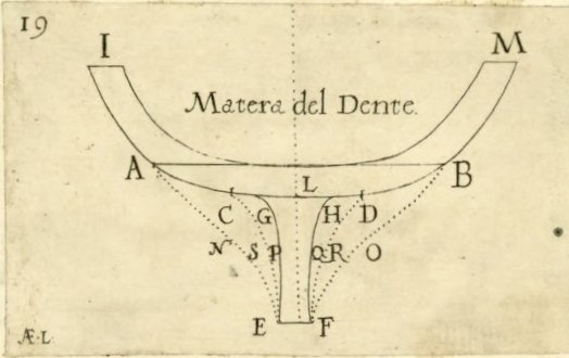
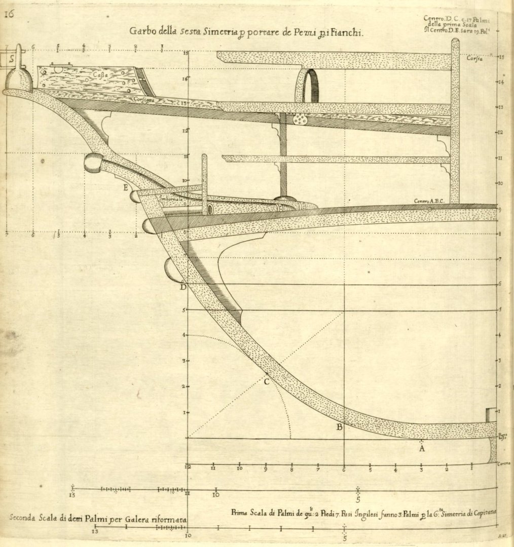
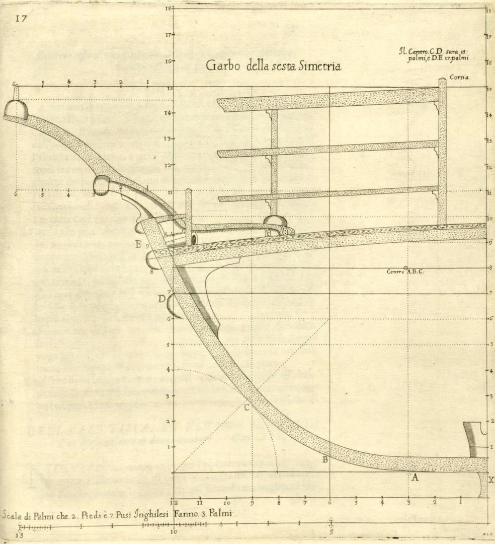
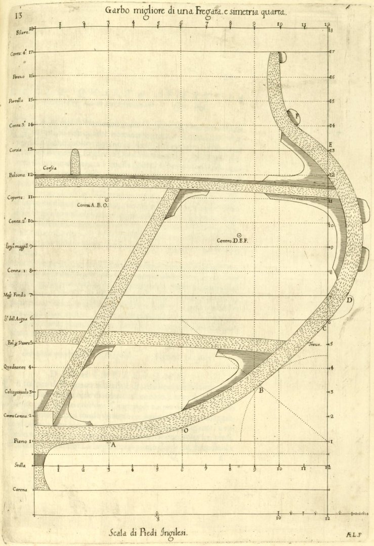
Hi @Cristiano, Thank you very much for your input. Dudley's use of Italian in his publication can not be surprising if he had ambitions for his work to become more widely known in Europe. Alongside Latin, the language of diplomacy, it was Italian, as a legacy of the Renaissance, that was widespread and virtually mandatory in the fields of science, culture and art at that time. Only later was it French, and then English. Ironically, this state of affairs may complicate matters somewhat today, however, it does not, after all, make Dudley’s work irrevocably hermetic. All that is required is just to meet a few conditions: first, one need to know somewhat about the subject matter; second, one must not belong to the Academic Society of Mutual Adoration (ASMA), since the content of Dudley's work, along with a number of other sources of the period, actually annihilates a significant part of modern publications by Society members, and thirdly, one must have civil courage in the face of the resulting, rather petty personal insults. That's really all one actually needs 😊. On one of the websites (Dell' Arcano del Mare - College of St George) one can read the following statement: “Dell’ Arcano is a magnificent work, both in terms of scholarship and visual appearance, and the Dean and Chapter’s copy has been much studied and appreciated by academics and laymen alike”. But where may be found the specific results of those studies and appreciations? Did everyone just look at the pictures like YouTube performances are watched? * * * Anyway, there is not much left to translate in this chapter… ON SHAPING THE RISING (HULL BOTTOM) with the ship’s floors, invented by the Author. Chapter XV. It is certain, and also demonstrated by the following figure, that the common Italian practice of using both the floors and the rising greatly alters the perfect shape of the ship's hull with this rising, and impedes its movement and steering; since a single inch of increase in the body under water of the breadth of the vessel, and near the rising (i.e. at the bottom), impedes the speed of the same vessel more than six inches of breadth at the surface of the water would do; and particularly when sailing close-hauled; and the reason for this is demonstrated in three different ways. The first method, which is the worst, is practised in the Mediterranean Sea by ordinary masters, and involves joining the rungheads of the floors with the keel by ordinary (i.e. more or less straight) lines, with the great impediment under water, thereby altering the perfection of the body, as can be clearly seen from the figure. The second method is much better than the first, and is known to be of much lesser hindrance, in the manner used in the Ocean Sea, especially by the English; which is to form the bottom starting from the floor at half the breadth at the rungheads; thus making the body of the vessel more perfect; and therefore the author has almost always worked in this fashion while building the preceding designs; although it still may be observed, that it is about half of the breadth at rungheads, as usual, yet without the aforementioned impediment. The third method is the author's own invention, and is considered here because it succeeds without impeding the true circumference of the floor with the keel, by means of the square [described] in Chapter IV, without which, even if applied in accordance with the design of the vessel, it would be impossible to achieve a good result; because in this case the floors are not joined to the keel by means of the divisions (‘scompartimenti’) of the flat of the floors, as it is in the first and second methods above, since the keel is joined to the floors in a way that it is only little more than the width of the keel itself, and these are joined together by means of the planking, as in the above drawings, and the following figure make it much easier to understand the reason for the lack of impediment, which will be possible to achieve under water. Demonstration of the three aforementioned methods with the quarter frame floor. Figure 19. DESCRIPTION. The letters ABEF, through NO, show the first method practised in Italy, to unite the rising EFGH with the floor ABIM, of which ABX is the breadth at the rungheads (‘il piano superiore’). The second method is shown by the letters CDEFSR. And the third method is shown by the letters EFGHPQ. It follows, then, that the wood between ABNO impedes the vessel's movement under water much more than the second method does for CD and RS; and in turn this second method impedes more than the third, for GHPQ; given that NO is much fuller of wood joining the keel with the floor than it is for RS, and this is fuller of wood than PQ, so the vessel will move much better, especially upwind, and will be even more stable than other vessels. And although warships built according to the third method described above may experience some pitching, yet only in calm conditions, this disadvantage will be of little importance (as has been noted on other occasions) compared to the great benefit and usefulness of the aforementioned speed and stability; because, thanks to this invention, the fleet will always be more victorious over the enemy, fighting from windward in the open sea. However, the most important consideration, regarding the third method mentioned above, will be to strengthen the rising well, joining the floor and the keel, by means of the planking both outside and inside, and other necessary fittings, so that the vessel does not suffer too much when it runs aground or rests on the ground; although in that part of the vessel where it rests there is little rising, and consequently the damage to the rising will also be little, and equal to that of other vessels; in any case, it will be good to strengthen that part of the vessel that must rest on land much more than in the other two preceding methods, for greater safety. Therefore, if one wishes to try this invention and be satisfied with it, one could build a ‘caico’ in this manner, and another of the same proportions and design, but in accordance with the first method according to the Italian custom; and thus, try these two ‘caiques’ side by side, and see which one performs better, both under sail and under oars, without incurring any additional expense for the initial trial and without any loss, since the ‘caiques’ can be used for galley service as usual. However, when testing at the larger scale, take care to make the keel two inches narrower towards the bow and stern than in the middle, because in this way it will cut through the water better, with less resistance under the water towards the bottom of the vessel, and will always sail better than others of the same design and proportion; and thus a passavolante of the seventh design built in this manner would sail much faster than other galleys, both under sail and under oars, in privateering, and even in rough seas, it would be in no way inferior to them; and in terms of holding the sails, it would be even better than galleys. In any case, the author's opinion is that the first method of shaping the rising for the rowing galleys is the safest, so that they will not suffer as much in calm seas, at anchor, being applied with the help of the square in figure 4 invented by the author, and presented in Chapter IV above; and that for square-rigged vessels and large high-board vessels, the second method is better and faster than the first; & the third method can be applied to smaller, very fast warships for attacking the enemy, such as frigates, & pinnaces, or pataches of the fourth preceding design & also of the seventh design.
-
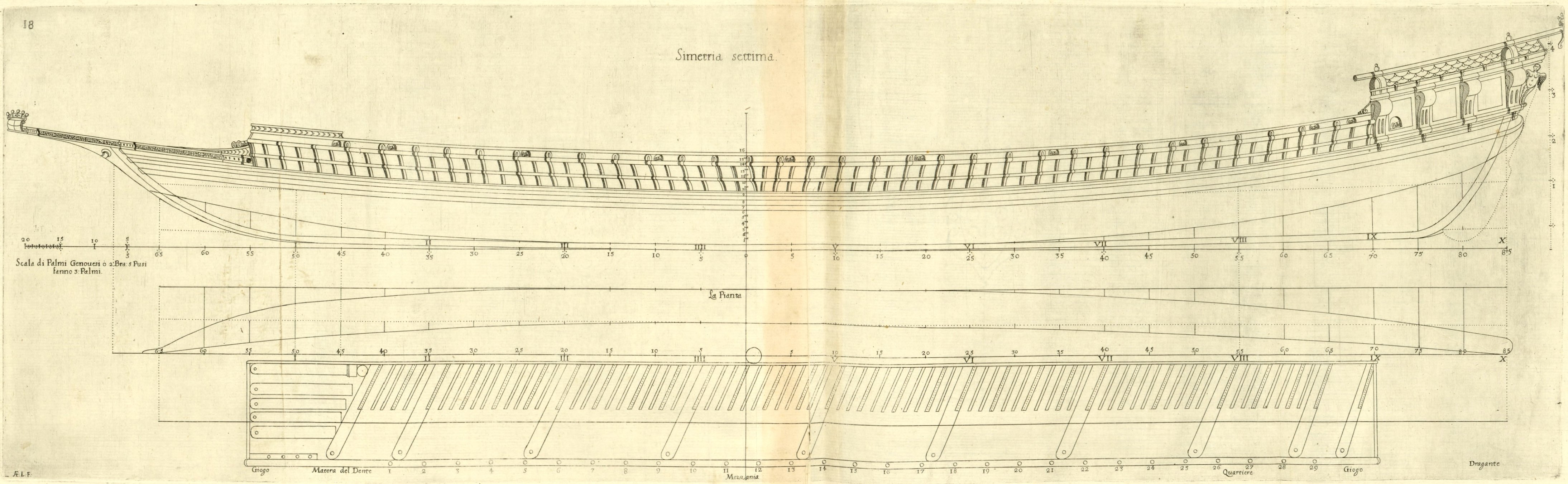
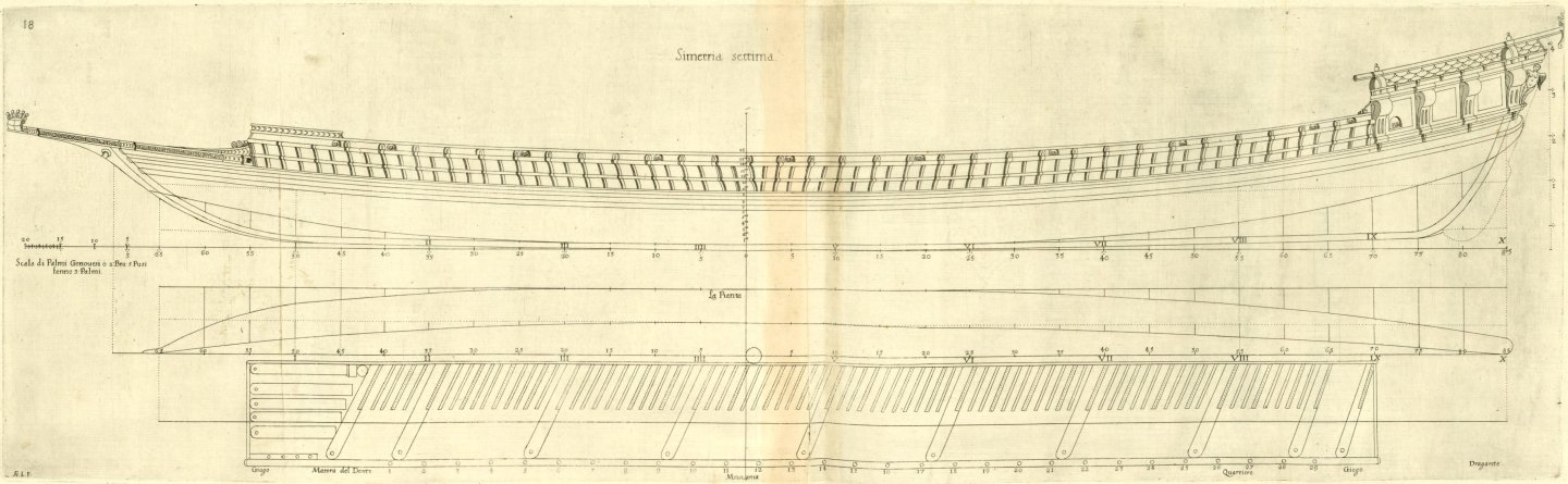
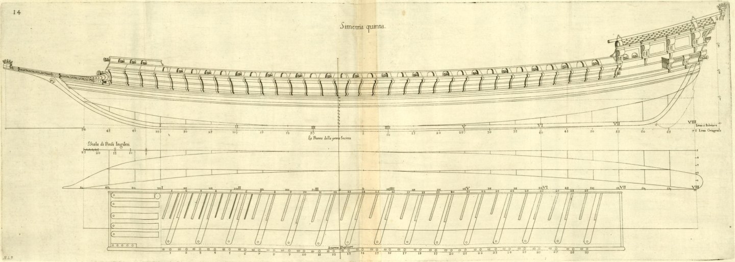
ON THE SEVENTH AND FINAL DESIGN of Passavolante long ten breadths. Chapter XIV. There is no doubt (as experience has shown) that it is possible to design ten-breadths long rowing vessels with benches, even though common galleys are only eight breadths long. Hence, the author already built a vessel like a galley, which he called a passavolante, which reached a perfect proportion of ten breadths, 20 palms wide and 200 long, and it held up very well, sailing as good as the others, with little difference: This vessel rowed with 28 benches, five [oarsmen] per oar, and carried more provisions (due to its length) than private galleys; and just as the number ten is the most perfect number, so the passavolante of the same proportion (provided it is well made) must be more perfect and much faster than other galleys; and although it is two breadths longer than them and narrower, it will in any case be more stable and much faster when rowing, due to the ingenuity of its construction; especially since it will row with 28 and 29 benches per side. However, it is reasonable to assume that the excellence of a very fast galley resulting from the aforementioned ‘passavolante’ design, ten times its breadth, is for privateering; and for the fleet, the fifth and sixth preceding designs of the Galerone and Galerata. It follows, therefore, that the author deemed it still expedient to produce the figure of the aforementioned passavolante; because no one has ever succeeded in such design, as this one; and all the more so because the science of its construction is much more curious and subtle than other designs; indeed, it is impossible to do so successfully using the common method of building galleys; and therefore it will not be so easy to steal the secret. Seventh design of Passavolante. Figure 18. DESCRIPTION The length of the passavolante at the first wale D, at no. 7 and where it touches the waterline, will be ten breadths of 20 Genoese palms per breadth, of which one cubit of three palms will be two and a half English feet, and from D, or the waterline, with the keel, the depth will be one third of the breadth of 20 palms, of which the keel will be one eighth of said third; & the deck camber will be equal to the height of the keel; and the hold at the deck at [level] number 8 above the keel will be one third of the said breadth, equal to the depth; and the length of the transom will be one quarter of the true breadth of 20 palms at the wale, [level] number 7, on the outside [of timbers]; and the same will be the breadth on the inside [of timbers] at [level] number 8. The breadth at the rungheads (the width of the narrowing line of the floor; ‘Il piano di sopra del maiere’) will be the half the breadth [taken] at D, [level] number 7, and the flat of the floor (‘il piano a basso del garbo’) will be a quarter of the same breadth, equal to the length of the transom; & this flat of the floor touches the keel, and the rising, which makes its shape a true circle, as can be seen better in the profile, and in the preceding drawing; because with the true circle the motion of the vessel will always be uniform, and faster, than it would be with the ordinary mould; and it would be more uneven underwater, which would prevent the ship from moving perfectly. The rising of the fore quarter frame will be two palms, and will be one and one third of the breadth (‘boccatura’) distant from the arc of the stempost at the first wale, from where the breadth (‘boccatura’) is measured; & the rising at the aft quarter frame, distant two and one third of the breadth (‘boccatura’) from the transom; will be two palms and two thirds, quite different from that of galleys, due to the greater length. The side railing (‘giogo’; see drawing), at the stern of the passavolante, will terminate one breadth (‘boccatura’) from the transom, and at the bow will only be two-thirds of a breadth (‘boccatura’) from the start of the wale; although the ‘tamburetto’ (rake?) will be 20 palms, i.e. equal to one breadth (‘boccatura’); and so this vessel will sail well with 28 and 29 benches per side, five [oarsmen] per bench. Each 'boccatura' of the ten mentioned above, at the wale, will be divided into three bends, & each bend is divided into five ribs, 85 aft and 65 forward, & each rib contains two parts, namely the floors and the futtocks. The height of the posts and benches, along with other details of the vessel, are clearly visible in the figure, and there are many of them, but they are of lesser importance and not so different from the usual ones that are produced. Note again that the author measures the true breadth outside the futtock at the first wale, and the waterline at [level] number 7, and inside [of the futtock] at the deck [level] number 8, which differs from common practice; because in this way the mould is much more stable than usual; and in terms of length, it will carry enough provisions, and perhaps more than other private galleys, and will not draw more than a palm's depth; which will make it sail more exquisitely and hold the sails much better. The [master frame] mould of the galeratina, of sixth design, serves for this seventh deign of passavolante, there being no other difference than the scale alone; since that is made for the breadth of 20 palms by the Author, of which two feet and seven English inches make three palms, and this is 20 Genoese palms, of which two feet and six English inches make three palms.
-
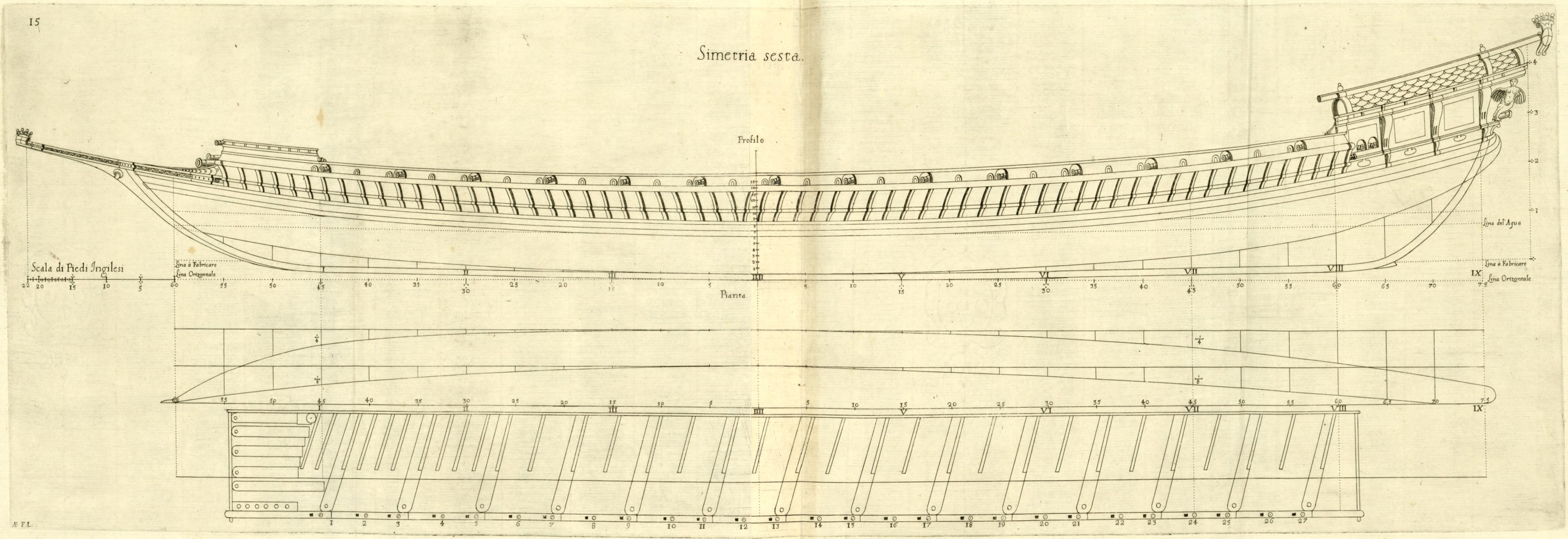
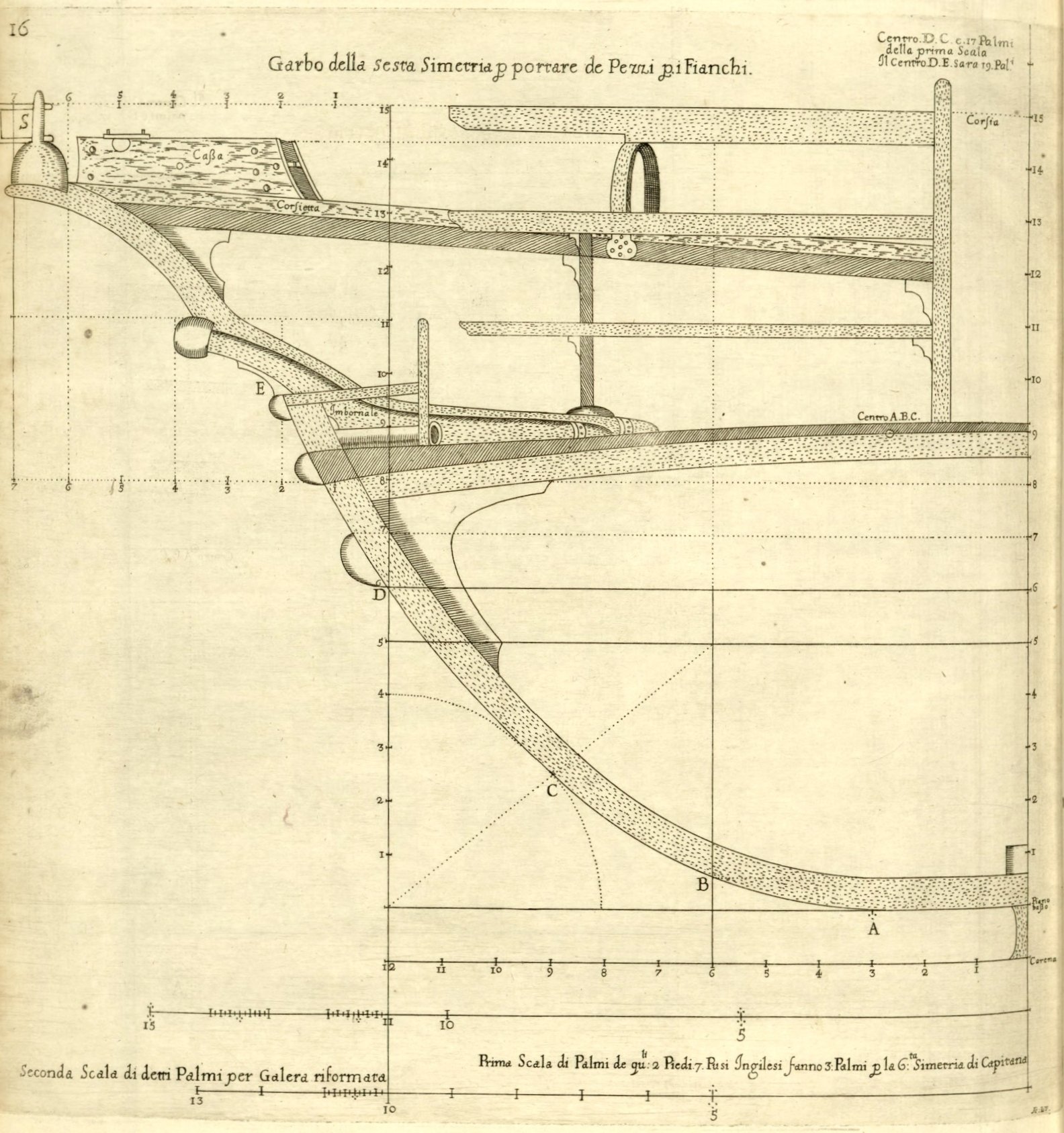
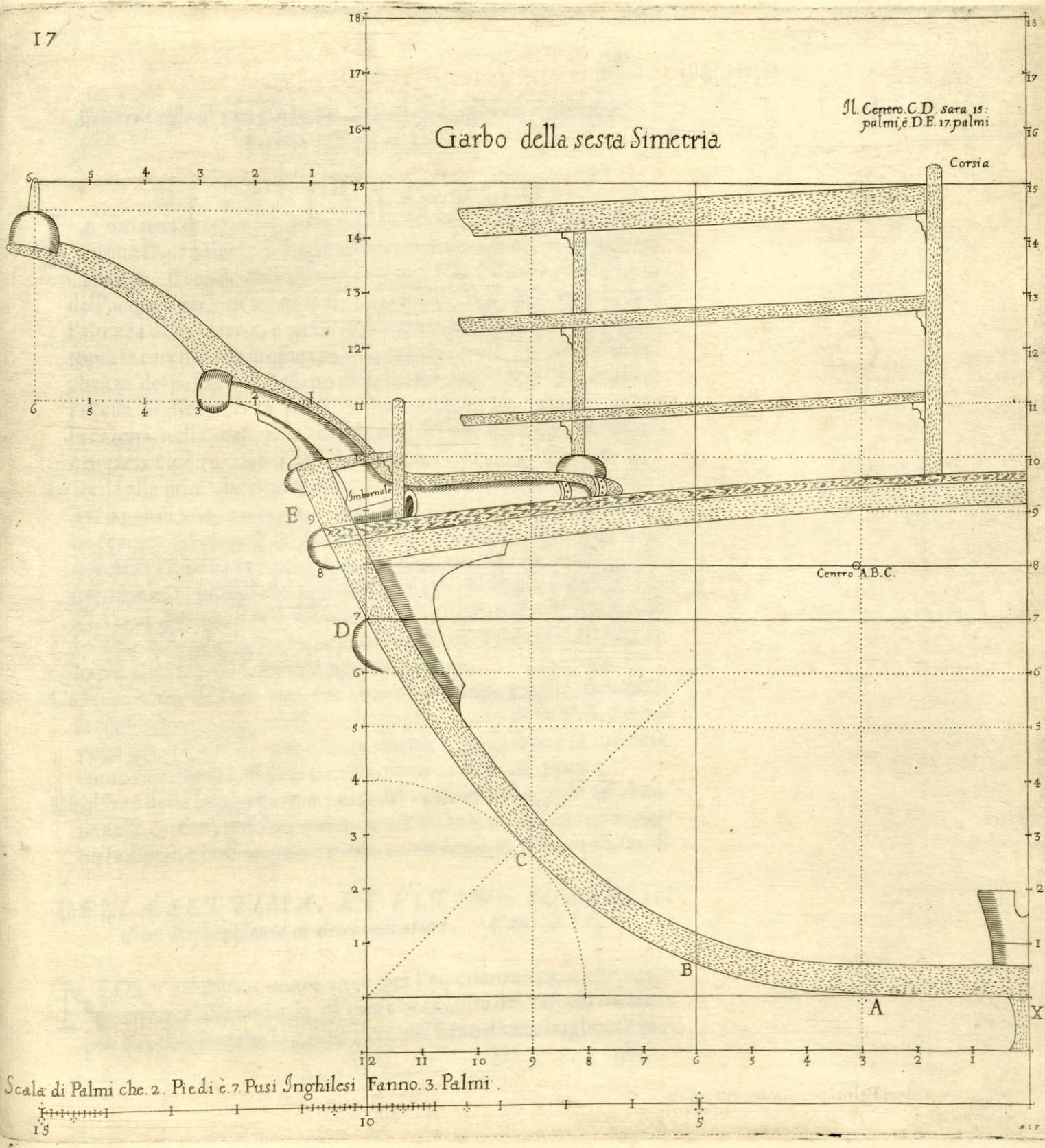
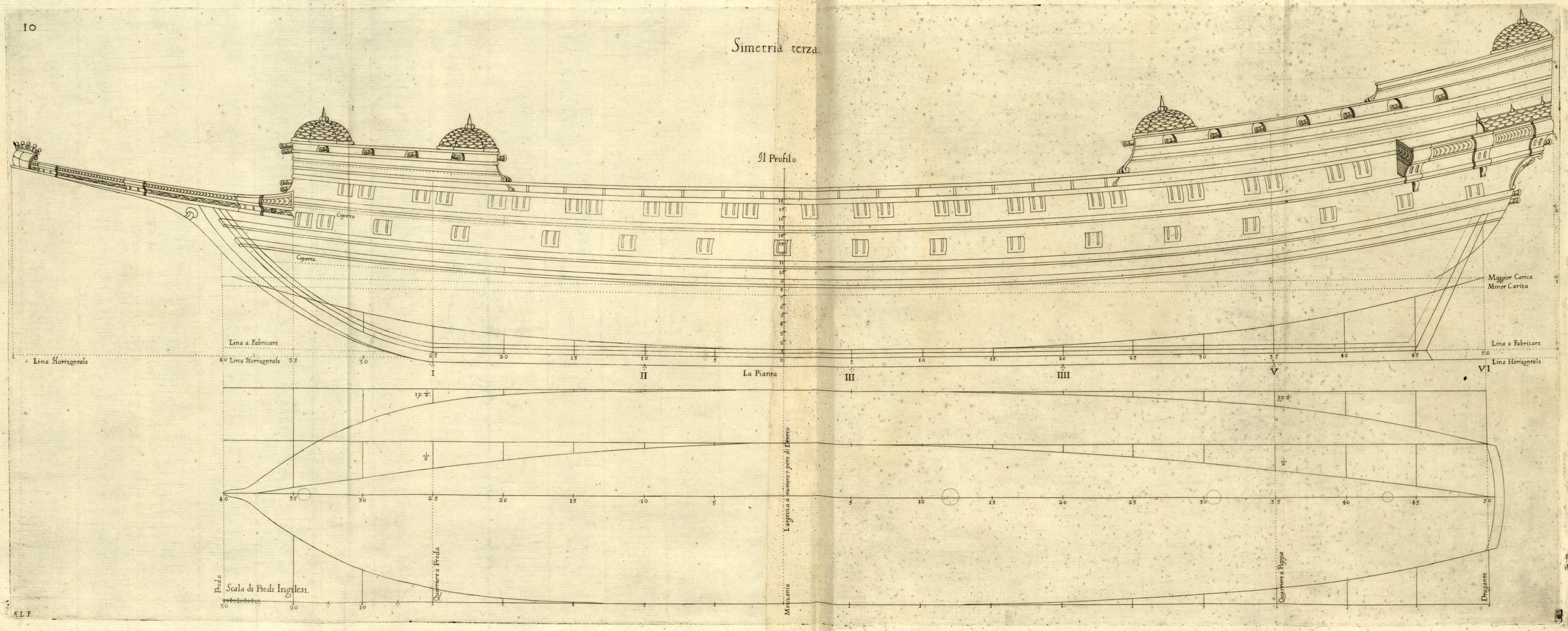
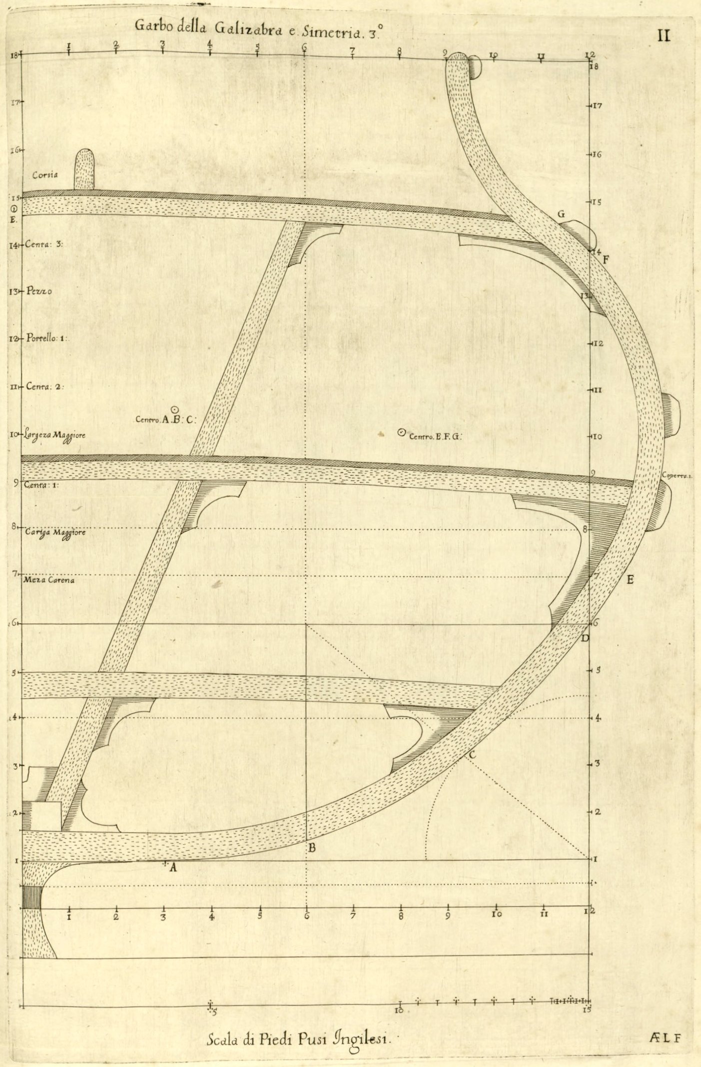
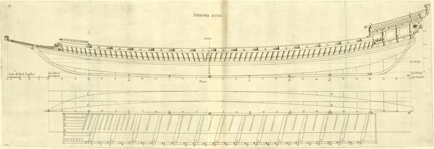
ON THE SIXTH DESIGN of Galerata, or improved Galley, long nine breadths. Chapter XIII. This Galerata, nine breadths long, can serve well as a flagship (‘galera Capitana’) in a fleet, and has been proved by its inventor to carry 32 good carriage pieces of artillery on her sides and at the prow, and with them has sailed much better than other galleys under sail and by rowing; while all vessels that are very stable are vulnerable somewhat at the stern in calm weather, but this is not a matter of concern in naval warfare, given the advantage of having so many good pieces on the sides when engaging in battle, as noted in Chapters II and VIII of Book Three; since this one is longer than common galleys by one breadth (‘boccatura’), it requires greater knowledge of naval architecture to make long, narrow vessels that are very stable; The author has discovered this secret through many years of experience, since anyone can build vessels that are shorter and wider than usual and are very stable, yet they will never match these in terms of speed, which is a major advantage when fighting from winward, as have already been mentioned. Therefore, the figure below can serve for two types of rowing vessels, by altering only the scale; one is a Galerata, 22 palms wide at the wale at [level] number 6, the other is a Galeratina, 20 palms wide; although they will be 9 breadths long, as noted above; and each cubit, or 3 palms of these, for the scale, make 2 feet and 7 English inches. However, the [master frame] mould of the Galerata is much more stable than the mould of the Galeratina, because the former must carry many pieces on its sides, and the latter will only carry swivel chambered guns (‘petrieri a forcina’), or pieces that are very light. However, the [master frame] mould of the Galerata will be 22 palms in breadth of those of the Author, as in Chapter III, and the [master frame] mould of the Galeratina will be 20 palms in breadth; and therefore the mould [in the figure] 17 of the Galerata serves for the mould of the Galerone, altering only the scale from 22 palms in breadth to 25 palms in breadth. Design of the Galerata, or improved flagship galley (‘Galera Capitana’). Figures 15, 16 and 17. DESCRIPTION. The design of nine breadths is measured similarly at the first wale D, 22 palms wide for breadth, and this will serve well for a [galera] Capitana: The depth of the vessel at [level] number 7, which is taken at the waterline, will be one third of the breadth, including the height of the keel, and this will be the height of the deck at [level] number 8 above the keel; and the length of the transom will be one quarter of the breadth of 22 palms. The breadth at the rungheads (the width of the narrowing line of the floor; ‘Il piano di sopra del maiere’) will be the half the same breadth, or 11 feet, and the flat of the floor (‘il piano da basso’), which rests on top of the keel, at the midship, will be half of that, or five palms and a half, that is, a quarter of the breadth. The rising at the first 'boccatura' will be twice the height of the keel, or one and three-quarter palms, and two palms at the seventh 'boccatura', or the aft quarter frame; and the same, one 'boccatura' towards the bow; in fact, the author, by means of his own invention, makes the hull of the vessel pleasant from stern to bow, which others consider very difficult, if not impossible, he has always done so, and consequently the body of the vessel is made much more perfect and even more stable. The other lines of the heights, sweeps, wales and rising, are easily deduced from the profile projection; and the breadths on the inside and the sweeps on the outside are deduced from the plan view and the mould view; and the run of the narrowing sides can be seen from the same plan. The [deck] camber at the center of the vessel shall be equal to the height of the keel; for galleys are commonly built with too much camber, and thus they are less stable and prone to rolling on their sides.
-
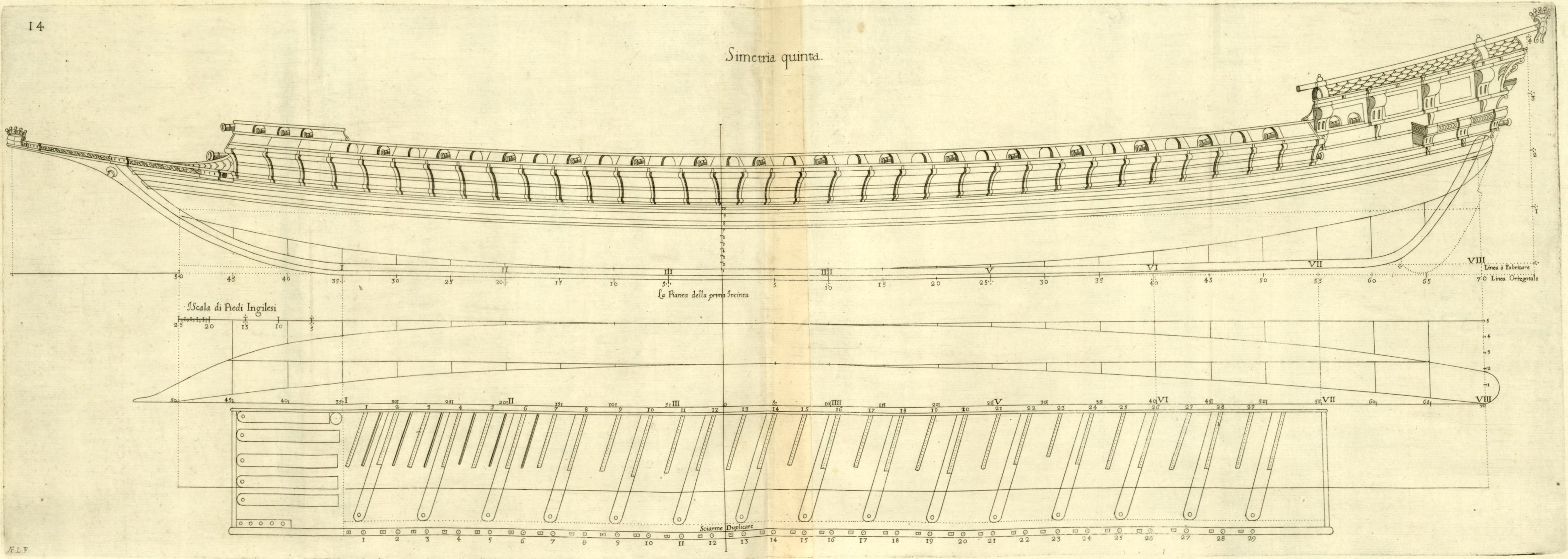
ON THE FIFTH DESIGN of Galerone long eight breadths. Chapter XII. The Galerone invented by the author as an improved galleass, will be more manoeuvrable than ordinary galleasses, accompanying the Christian fleet of galleys, especially when rowing; given that the Galerone can be dismasted and can be rowed against the wind, as galleys do (which galleasses cannot do in any way, as noted in Chapter II), as well as draw less water than them; so that the Galerone can enter any port where a 30-bench flagship galley (‘galera Capitana’) can enter; and the Galerone will carry fifty pieces [described] in Chapter VII, Book Three, and twenty ‘petrieri’ (light chambered guns); and it will also carry a ‘rombata’ (heavy ‘corsia’ gun) at the bow, like galleys; and the stern will be bastard, in the manner of galleys, but a little wider, that is, one third of the breadth at the transom; and in galleys it will be only one quarter; and therefore a Galerone of the Author can keep company continuously, and in every way (being well armed) with the galley squadrons; & in this it will be very different from common galleasses; and therefore these galeroni will be very useful for accompanying the Christian fleet in place of galleasses, and will be of greater strength with artillery, and of at least a third less expense in the fitting-out. However, note that the [master frame] mould of the following Galerata, 22 palms broad, will serve for this Galerone, by altering only the scale, that is, from 22 palms of breadth to 25 at the wale. Design of the Galerone. Figure 14. DESCRIPTION This Galerone has eight ‘boccature’, or breadths at the first wale D, for length; the depth at number 6 at D will be one third of the same breadth of 25 palms, that is, with the entire keel; and the hold above the keel will be less; and the length of the transom will be one third of the true breadth at wale D, or waterline. The breadth at the rungheads (the width of the narrowing line of the floor; ‘Il piano di sopra del garbo’; actually should read: ‘Il piano di sopra del maiere’) will be half the breadth, and the flat of the floor (‘il piano più basso’) will be a quarter of the same breadth; and the breadth at [level] number 7 will be 25 palms on the inside [of timbers], and the same at [level] number 6 on the outside [of timbers]; and the loaded vessel will not draw more than eight palms and three quarters in depth, like a galley Capitana. Each ‘boccatura’ length will be divided equally into three bends, & each bend into five ribs, & each rib is composed of the floor, and futtock, without toptimber, and the ribs along with the rising line form the hull of the vessel above the keel. Observing the difference between the [straight] horizontal line (‘linea orizontale’; see figure) and the [curved] actual construction line (‘linea di fabbricare’; see figure) in the author's drawing, note that these long vessels are designed and build using the construction line and not the horizontal line, because vessel will quickly drop to that line by itself when launched and sailed. The deck camber will be approximately one palm at the center, equal to the entire height of the keel, as per the mould. The rising line at the first ‘boccatura’, where the keel begins (i.e. above the junction of stempost and keel), will be two and a quarter palms, that is, twice the height of the keel in this design; & at the sixth ‘boccatura’, the rising line will be only two inches more. The other lines are many, and they can be extracted from the profile, mould, and plan projections. The walkway (‘corsia’) will be three times the height of the keel and two and a half times as wide on the inside.
-
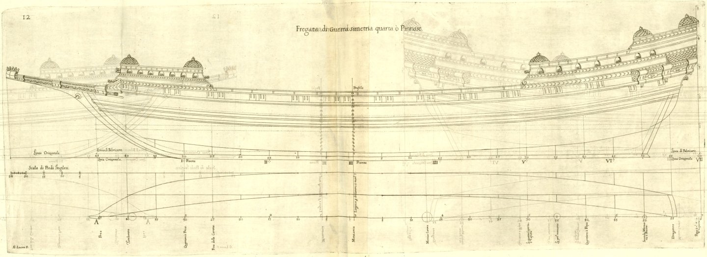
ON THE FOURTH DESIGN of Frigate long seven breadths. Chapter XI. While the riches were already being transported from the West Indies by certain long square-rigged vessels, called frigates, which sailed well but were not very seaworthy at sea; and now the warships are called Dunkirk frigates in Flanders, however, the author gives the name frigate to this fourth design of square-rigged vessel, which is longer than the mentioned designs, as it has length of seven breadths, including the stern; yet it will be very strong and will carry 50 or 60 pieces [described] in Chapter VII. It will withstand all kinds of bad weather, thanks to its stiffness, and will in any case be much faster than other square-rigged vessels, and will be able to sail safely to the West Indies and return in good season, carrying rich cargoes; indeed almost three of these frigates can be fitted out at the same cost as a large galleon of the Indies. The pinnaces, mentioned in the preceding Third Book, are of the same proportions as the frigates, but are much smaller than them; in any case, they will carry twenty-five or thirty light pieces [described] in the aforementioned Chapter VII and can row well in calm weather, yet without benches or slaves; and so will the aforementioned frigate, and therefore it is a very useful warship in the Mediterranean Sea; and due to its length, it must have a well reinforced deck, with a small overbridge (‘corsietta’) in the middle. Design of the Frigate. Figures 12 and 13. DESCRIPTION. The frigate of the fourth design is seven breadths long, including the entire stern, as mentioned above, and not to the wing transom. The breadth at the first wale C will be 24 feet on the outside [of timbers], and the same on the inside at D, and the depth (‘il fondo’) one third; also the greatest breadth at [level] number 9 will be 27 feet, of which, up to the second transom, the vessel will be about six breadths long, that is, six times 27 feet, at the second wale: The breadth of the first transom, where the first wale ends, shall be 12 feet or half the true breadth of this design, & the second transom terminates the second wale. Each [length section of one] breadth is divided into three bends, of five ribs per bend, and each rib is in three parts, as explained in the preceding designs; which are guided by the rising [line] in the manner as in the previous designs; and its run is found on the profile view at the fore and aft quarter frames, being one breadth at the height of first wale from the stempost, and from the transom itself at the stern, from where the distance of those quarter frames is counted. The height of the ship's side at the midship shall be two-thirds of the breadth at the first wale, by design; and by means of the ribs, the body of the vessel is formed. The other lines of the profile, and the mould, and of the plan are taken from the drawing and are very different from the preceding figures; and that at C is the waterline; and with this drawing the four designs of square-rigged vessels are completed, and the rowing ships follow.
-
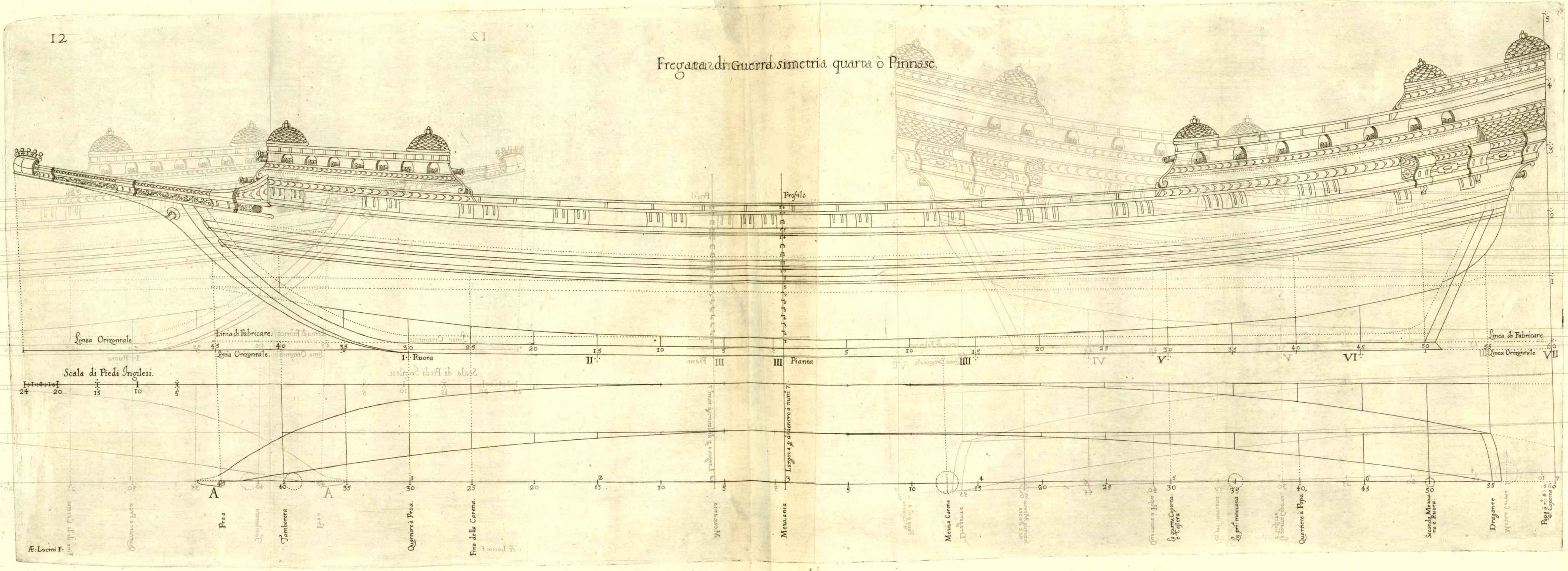
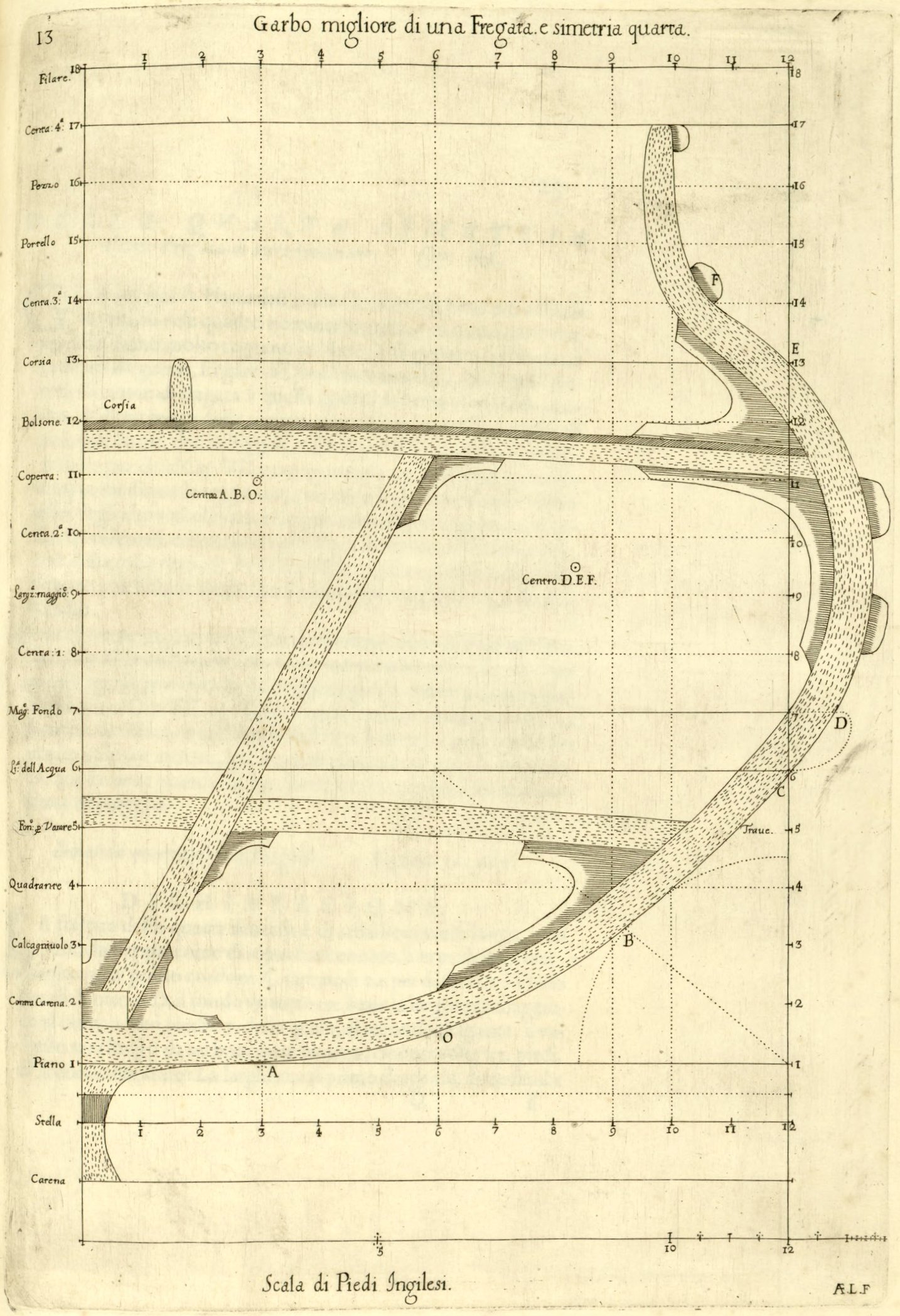
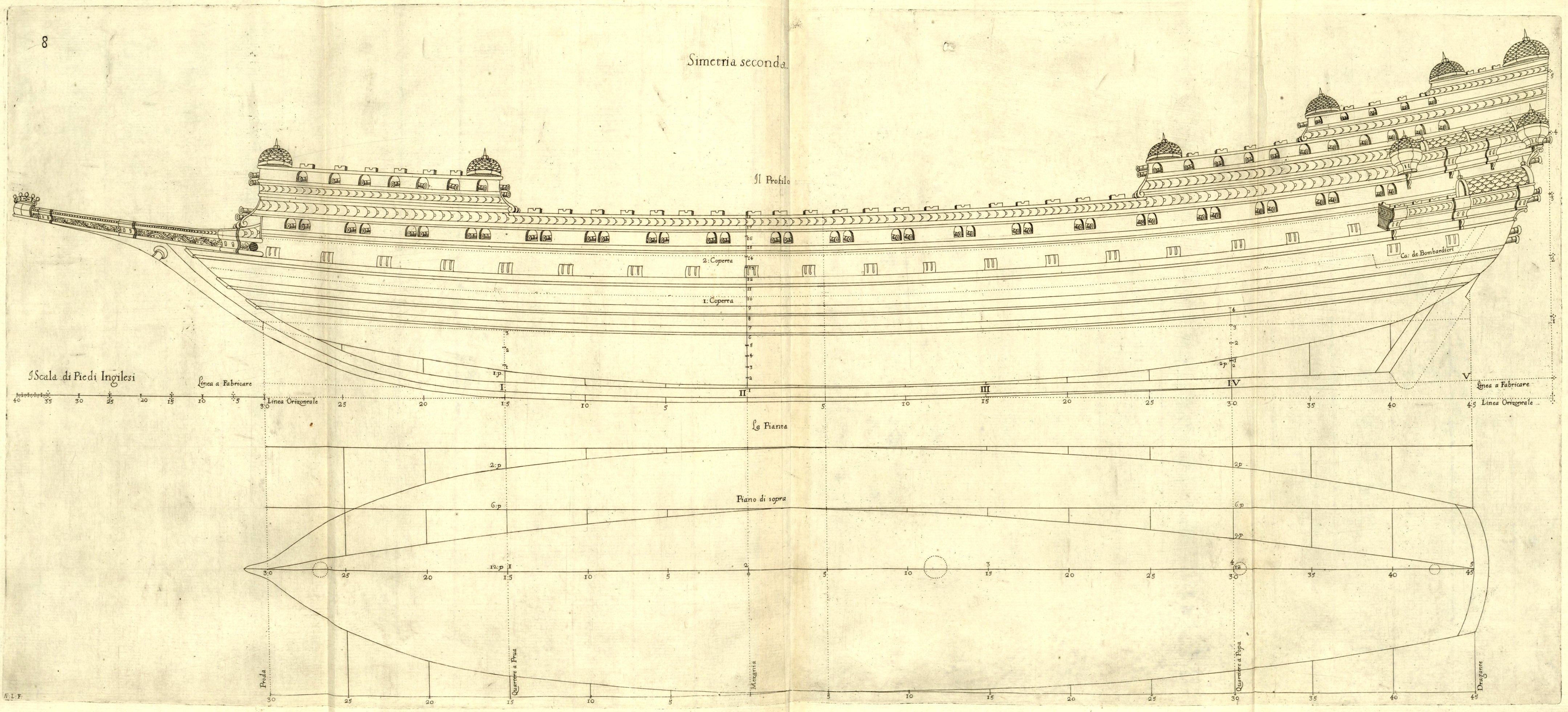
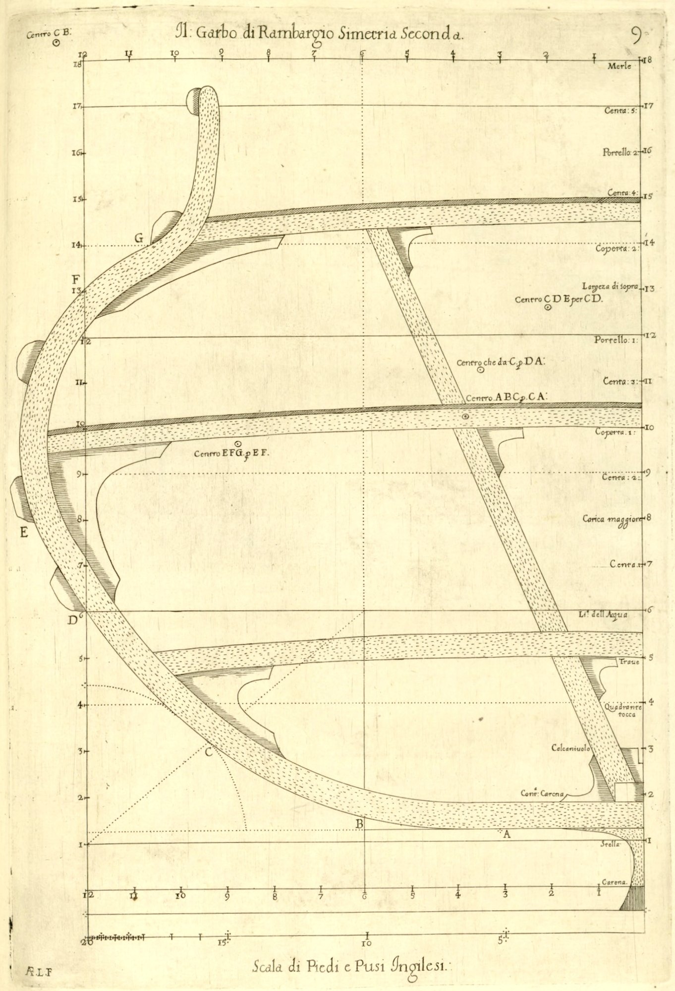
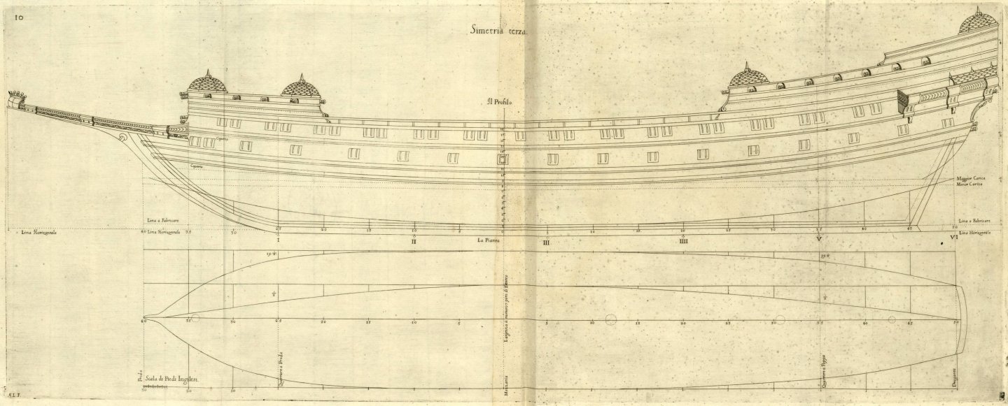
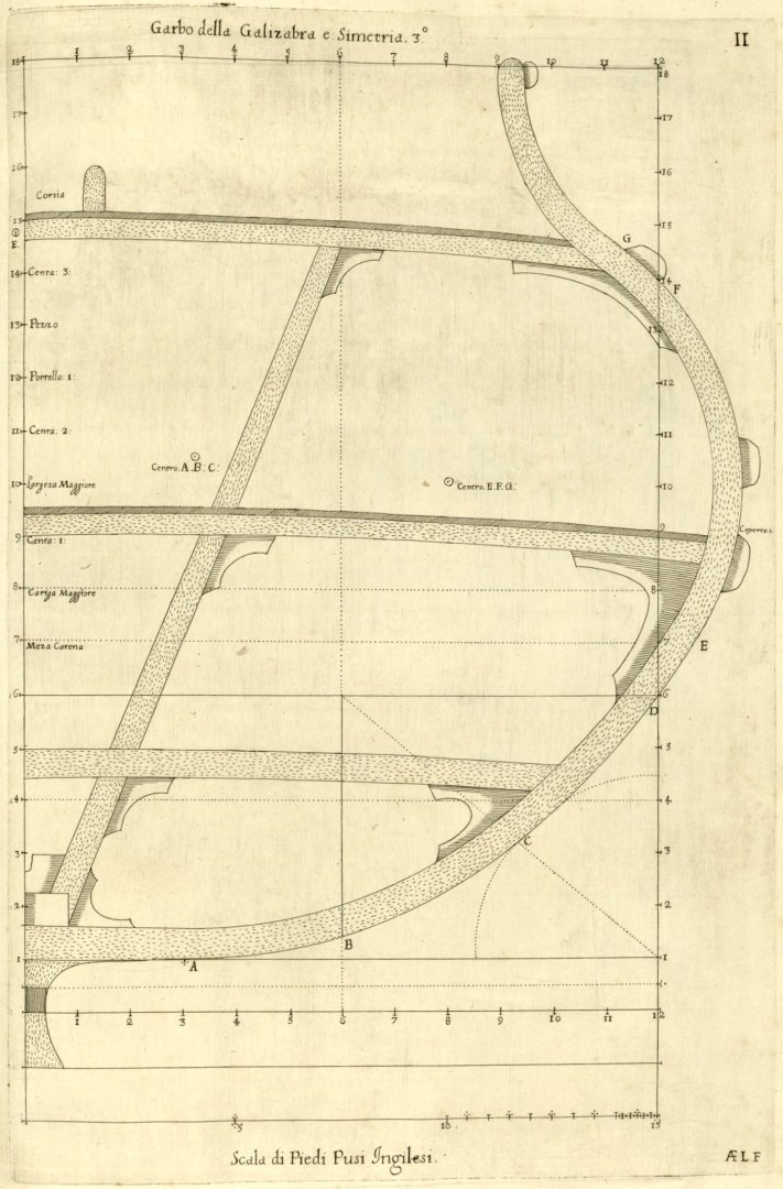
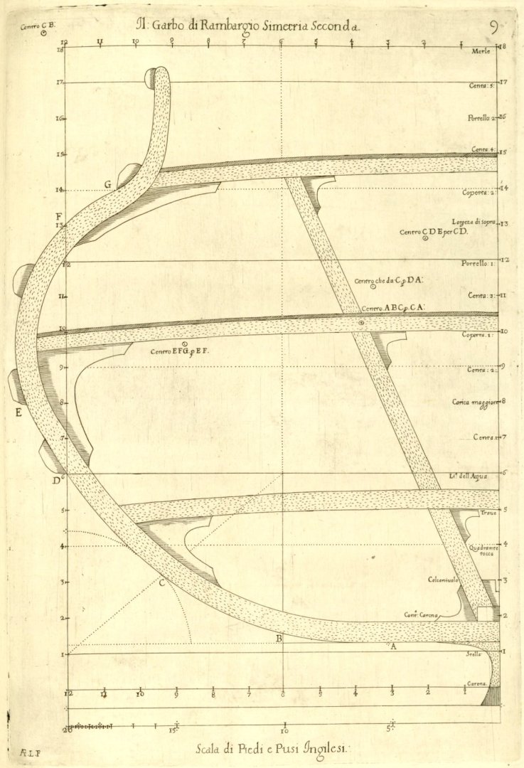
ON THE THIRD DESIGN of Galizabra long six breadths. Chapter X. Galizabra is the name given by the author to the ships of the length six times the breadth at the first wale, by design, invented, and built by himself, with great success, both for their speed and their stability, and mainly for the strength of their artillery in fighting safely from windward, which is a major advantage, as we have noted elsewhere in this book; in addition, the cost of fitting out one of these galizabras will be less by a quarter than that of the improved galleons or rambargi, and it will be in no way inferior to them in terms of strength for making a good day's progress, even though they have more draught; in fact the galizabra, with its shallower draught, will be faster in every respect than the said galleons and rambargi; It is true that this will not be as suitable as those for long voyages to the Indies, but it will be much better for accompanying the fleet of galleys and galleasses; and much easier to row in calm weather; moreover, galizabras can be kept under the arches [of sheds] at less expense, as galleasses are, by simply removing the masts; & this is a great benefit, because in this way they will be kept many more years, at little expense and with great savings; and the same applies to the frigate of the fourth design, which follows. Design of the Galizabre. Figures 10 and 11. DESCRIPTION. This galizabra must be thirty English feet wide at the first wale, and six breadths long, that is, thirty feet of breadth, or width, and that makes 180 feet in length up to the first transom, which is fifteen feet wide itself, or half the breadth; & each [length section long one] breadth is usually made up of three bends of five ribs per bend; & the first wale must be laid at [level] number 6 above the keel, however, it is not shown in the profile projection, by mistake, as it was forgotten when drawing; and it must be parallel to the second [wale]; and so it will be easy to append the said first wale between numbers six and seven. Each rib, as in previous designs, consists of three parts, namely the floor, the futtock, and the toptimber; and the rising [line], which guides the ribs above the keel, must be divided (shaped) into portions of the true circle, in accordance with the profile view; and of these ribs the body of the vessel is formed. The hold, at midship up to the first deck, will be one-third of the breadth, or ten feet, and so much will be the waterline from the bottom of the keel. The decks shall follow the run of the wale; and the height between the two decks shall be six feet, or one-fifth of a thirty-foot beam. The upper line of the mould (actually half the breadth of design grid, or more precisely: maximum width of the line of the floor or breadth at the rungheads at the master frame) will be half the breadth, or 15 feet, and the lower horizontal line (actually half the length of the floor, and more precisely: the flat of the floor), where the rising touches the floor, must be half the upper horizontal line [of the mould], or seven and a half feet. Note that in this design there are two transoms for strengthening the stern; the first transom terminates the first wale, and the second transom terminates the second wale. Note also that the greatest breadth of the vessel at [level] number 9 will be 34 feet, which will make six breadths [length] including the entire stern: The [dead]rise at midship will be half more above the keel; and therefore this design does not require a false keel, because the keel alone without the said [dead]rise will be [as much as] one part and a half: And the other lines, which are many, can be derived from the profile view, and the mould, from the figure above.
-
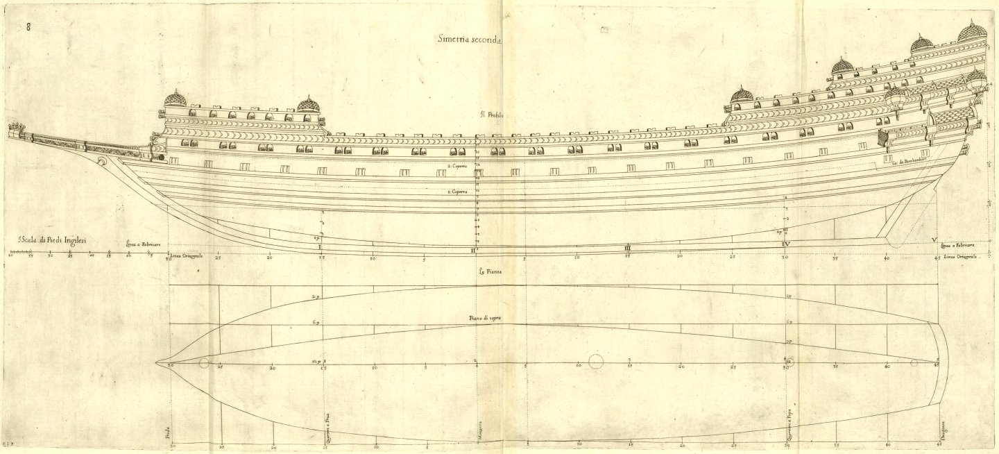
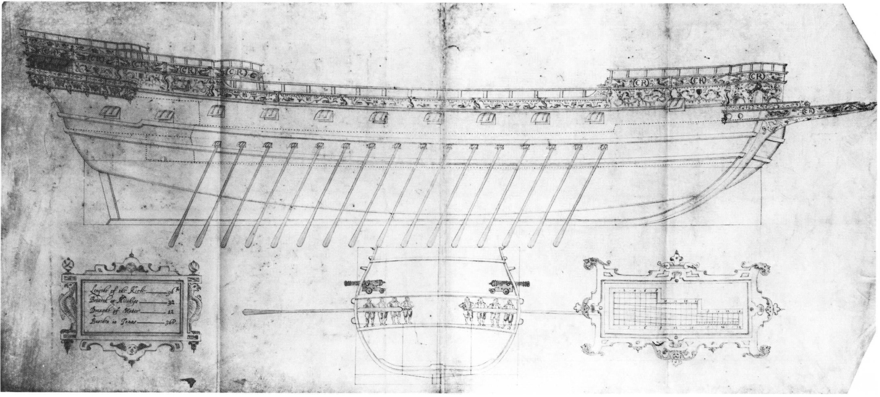
ON THE SECOND DESIGN of improved Rambargio long five breadths. Chapter IX. The rambargi (rowbarges), so named by the French when referring to the long, low vessels of the Royal Navy of England, are very different in design from galleons and warships of other countries; although the author's rambargi are quite different from those of England, they are even faster and more stable, have less draught, and carry more pieces for fighting from windward. Therefore, the author's rambargio will be five breadths long, at the first wale, and will have two and a half decks, with the gunroom still; and this design is intermediate between a galleon four breadths long and a following galizabre six breadths long. However, rambargi can easily sail to the West Indies and carry sufficient provisions for the journey in good weather, transporting cargo and valuable merchandise safely. But for longer voyages, such as to the East Indies or elsewhere, galleons of the first symmetry will be much more suitable. Second design of the improved rambargio. Figures 8 and 9. DESCRIPTION The width of the vessel at midship, at the first wale, which is called here the breadth (‘boccatura’), will be 40 English feet, and the waterline at [level] number 6 will touch the wale; and the length at this level to the wing transom will be five breadths, or 200 feet. The hold will be one third of the breadth, or 13 feet and 4 inches, and the same will be the draught, by design, which will immerse the vessel together with the keel; although with larger load it will draw more than 14 feet. The rake of the stempost up to the first wale will have a length of one breadth, & [the total stempost's] height from the curved line of the keel (‘linea da fabbricare’; see figure 8.) two thirds of this, & at the wing transom three quarters: The other wales are almost parallel to the first wale; and the height between the two decks will be the sixth part of the breadth, that is, six feet, and eight inches. The height of each line is taken from the profile; but the width is shown by the plan, together with other lines, of which there are several; from which the wing transom will be half a breadth wide. The rising [line of the floor], at the fore quarter frame, will be one foot and a half, and at the aft quarter frame it must be three feet. The vessel, at the waterline at [level] number 6 and outside the futtock, will have a breadth of 40 feet; and the same breadth inside the futtock at [level] number 7, but the greatest breadth of the vessel, which is at [level] number 9, will be approximately 45 feet wide; and thus the vessel will be slightly longer overall [, that is] five times that breadth of 45 feet. And this serves as a cautionary note.
-
Yep, at the very end of the whole chapter, along with some other Dudley's 'lesser' inventions, genuine or misappropriated .


-(MeisterDrucke-87832).jpg.ed3d91b49c3cb3ec8ef126c800116f1b.jpg)
.jpg.5bfa3537dc76396c5b1bb4f1d5a578b5.jpg)