.jpg.6c90d67e7e9071af590f4d4a2a8bc908.jpg)
Waldemar
-
Posts
1,003 -
Joined
Content Type
Profiles
Forums
Gallery
Events
Everything posted by Waldemar
-
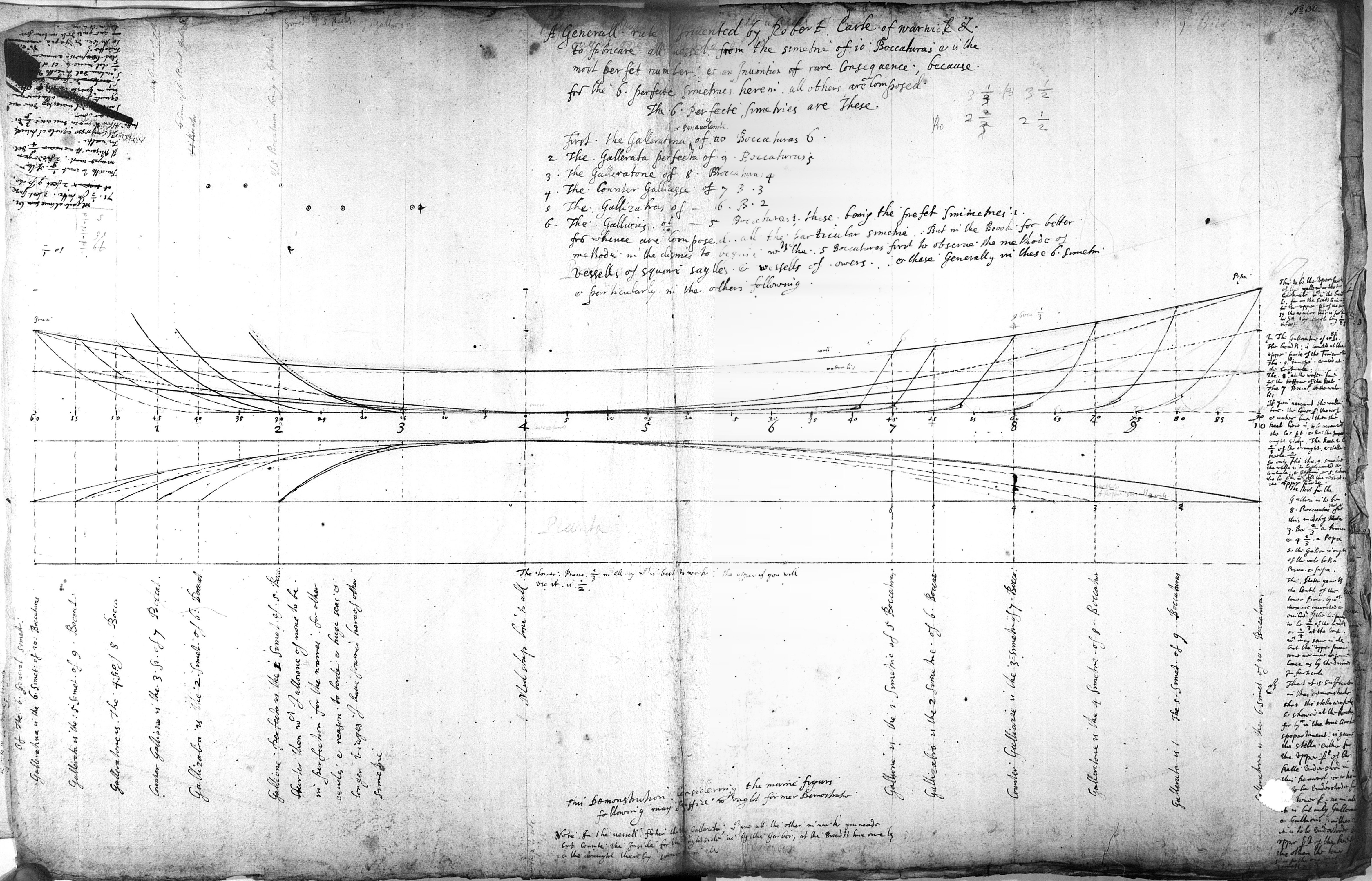
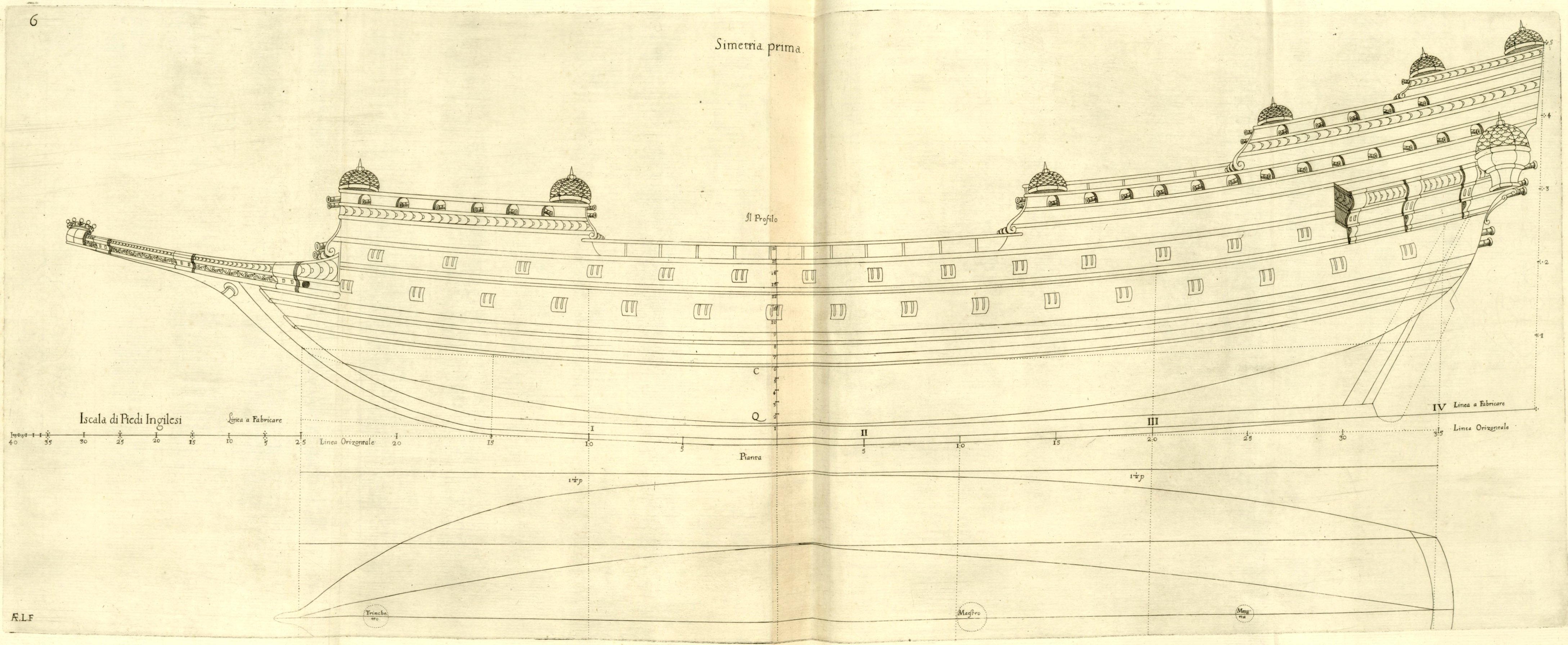
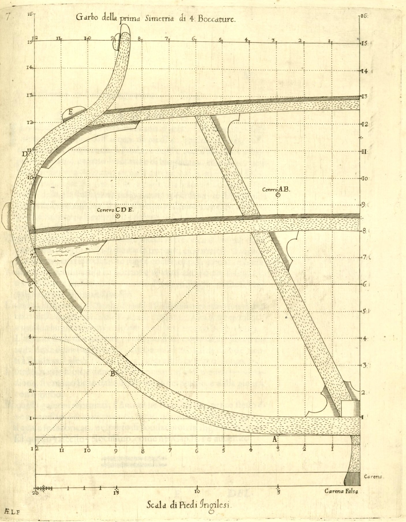
.thumb.jpg.c6343966b029e7941df5b987d129aac6.jpg) ON THE FIRST DESIGN of improved galleon long four breadths. Chapter VIII. This design by the author of improved galleons is very well suited for sailing and for fighting at sea, being four widths, or breadths long at the first wale; so they can be used well for short voyages, and even for long voyages to the East Indies, for warfare, but not for carrying large quantities of ordinary merchandise, as the large carracks of Portugal do; although these galleons by the Author will carry enough valuable goods, provisions for living, and ammunition for the number of people who must be employed on such a long voyage; and they will also withstand the fortunes of the sea very well, carrying many of the gun pieces mentioned in the previous chapter; in such a way that they will be much stronger and much faster than the other galleons and carracks of the Indies; although for short voyages they will be armed with a third more pieces, and carry a greater number of men, proportionally, they will always be faster, more stable, and more manoeuvrable in combat from windward than ordinary galleons. Design of the improved galleon. Figures 6 and 7. DESCRIPTION The vessel will be wide across the midship at the first wale, which touches the waterline in the middle, by 40 English feet; which wale starts at the stempost and ends at the wing transom at the stern, and is four breadths long, that is, 40 feet by design; and the depth in hold will be one third of the breadth, or 13 feet and 4 inches, up to the waterline, which is measured from the lowest part of the keel itself; although with the cargo of provisions, the vessel will not draw less than 14 or 15 feet and a half deep; and the [second] wale, or string, parallel to the first one, marks this limit. Each section [of the length], long one [ship’s] breadth of 40 feet, is divided into three bends of five ribs per bend, & each rib is divided into three parts, namely floors, futtocks, and toptimbers, and the rising [line of the floor] guides these above the keel; and the said rising is divided (shaped) into portions of a true circle [described] in Chapter IV and starts and terminates at the stem- and sternpost, as can be seen more clearly in the profile projection. The rake (in the original text: ‘The height’) of the stempost, where the first wale terminates, will be two-thirds of the breadth, and the sternpost will be four-fifths; and there the wing transom will be 20 feet, that is, half the breadth of the hull: The height between the two decks will be six feet and eight inches, being one-sixth of the said breadth: The height of the rising at the fore quarter frame will be 1 foot and a half, and 3 feet at the aft quarter frame at number 20. The other lines, both outside and inside, which are many yet of less importance, can be easily deduced from the drawing itself of the profile projection and from the plan view, with some skill. Of these improved galleons, the author had one built for himself, of 300 tons, to sail in the Indies, named the Great Bear, which was built in the port of Southampton in England; and this vessel proved to be very fast, as mentioned in Chapter II.
ON THE FIRST DESIGN of improved galleon long four breadths. Chapter VIII. This design by the author of improved galleons is very well suited for sailing and for fighting at sea, being four widths, or breadths long at the first wale; so they can be used well for short voyages, and even for long voyages to the East Indies, for warfare, but not for carrying large quantities of ordinary merchandise, as the large carracks of Portugal do; although these galleons by the Author will carry enough valuable goods, provisions for living, and ammunition for the number of people who must be employed on such a long voyage; and they will also withstand the fortunes of the sea very well, carrying many of the gun pieces mentioned in the previous chapter; in such a way that they will be much stronger and much faster than the other galleons and carracks of the Indies; although for short voyages they will be armed with a third more pieces, and carry a greater number of men, proportionally, they will always be faster, more stable, and more manoeuvrable in combat from windward than ordinary galleons. Design of the improved galleon. Figures 6 and 7. DESCRIPTION The vessel will be wide across the midship at the first wale, which touches the waterline in the middle, by 40 English feet; which wale starts at the stempost and ends at the wing transom at the stern, and is four breadths long, that is, 40 feet by design; and the depth in hold will be one third of the breadth, or 13 feet and 4 inches, up to the waterline, which is measured from the lowest part of the keel itself; although with the cargo of provisions, the vessel will not draw less than 14 or 15 feet and a half deep; and the [second] wale, or string, parallel to the first one, marks this limit. Each section [of the length], long one [ship’s] breadth of 40 feet, is divided into three bends of five ribs per bend, & each rib is divided into three parts, namely floors, futtocks, and toptimbers, and the rising [line of the floor] guides these above the keel; and the said rising is divided (shaped) into portions of a true circle [described] in Chapter IV and starts and terminates at the stem- and sternpost, as can be seen more clearly in the profile projection. The rake (in the original text: ‘The height’) of the stempost, where the first wale terminates, will be two-thirds of the breadth, and the sternpost will be four-fifths; and there the wing transom will be 20 feet, that is, half the breadth of the hull: The height between the two decks will be six feet and eight inches, being one-sixth of the said breadth: The height of the rising at the fore quarter frame will be 1 foot and a half, and 3 feet at the aft quarter frame at number 20. The other lines, both outside and inside, which are many yet of less importance, can be easily deduced from the drawing itself of the profile projection and from the plan view, with some skill. Of these improved galleons, the author had one built for himself, of 300 tons, to sail in the Indies, named the Great Bear, which was built in the port of Southampton in England; and this vessel proved to be very fast, as mentioned in Chapter II.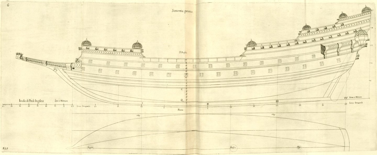
-
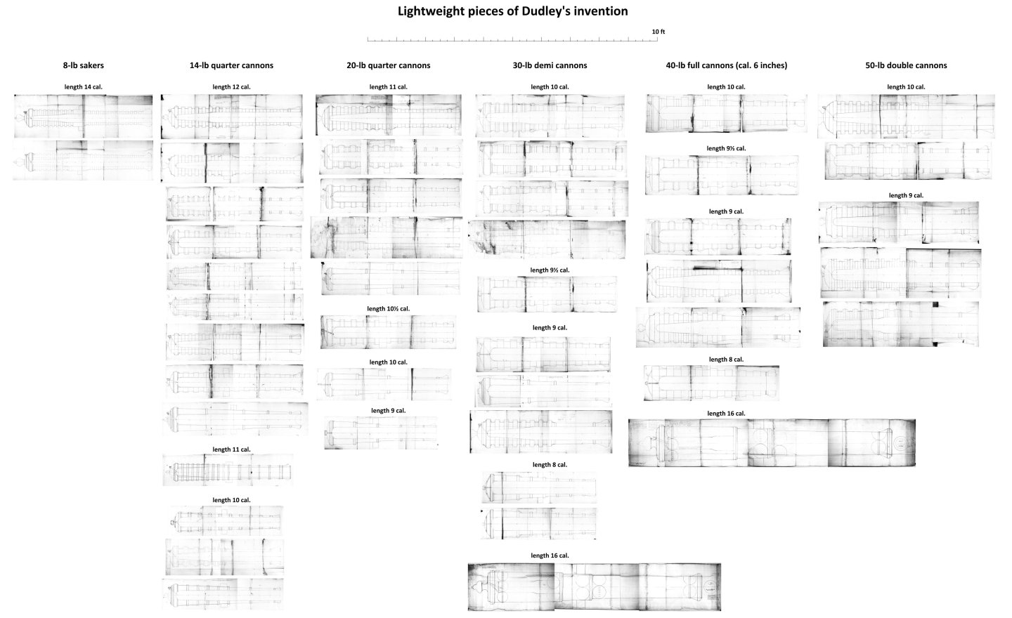
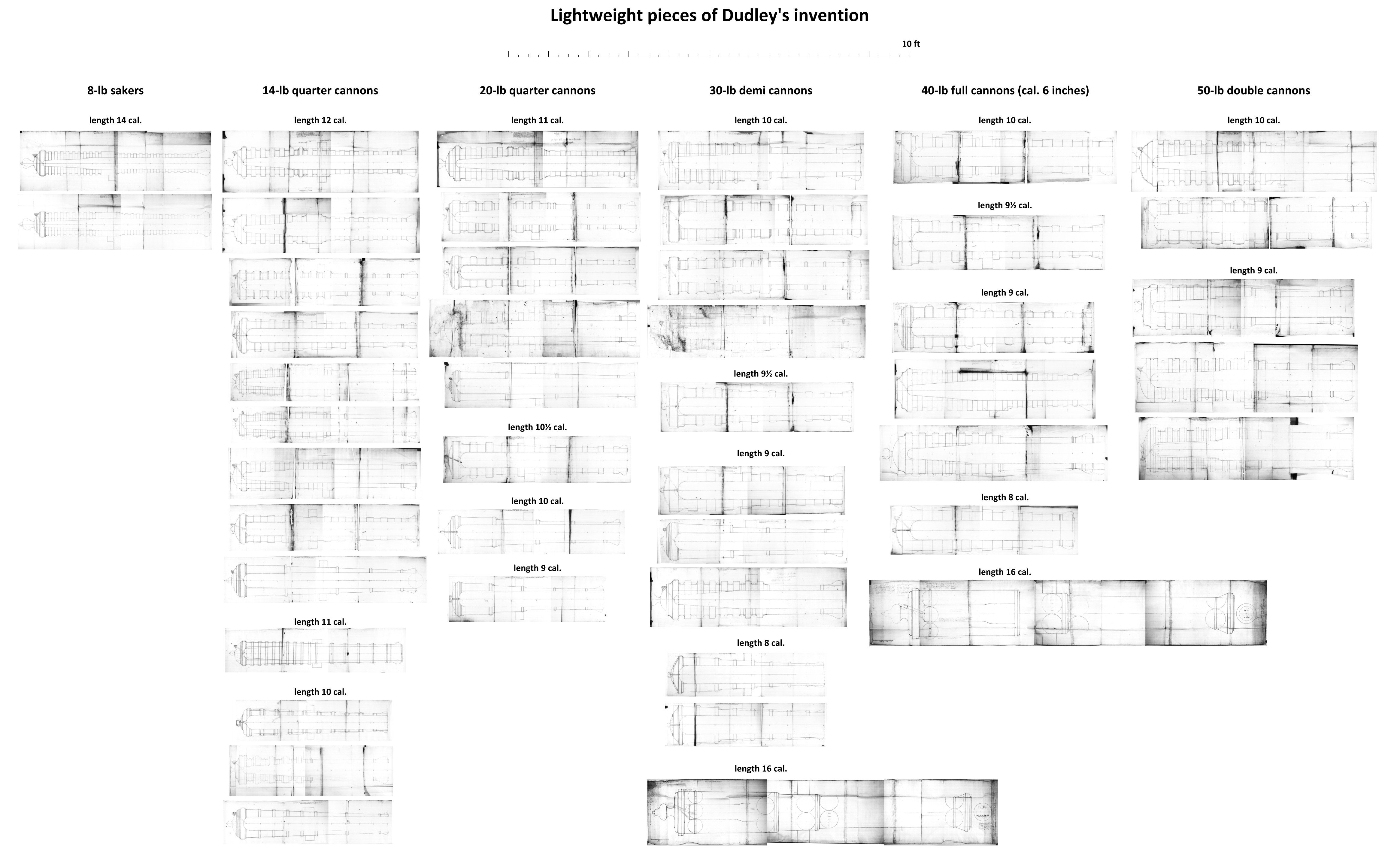
Remarks on Chapter VII: It should be clearly emphasised that the lightweight pieces designed by Dudley must have been the result of experiences gained, among others, during the campaign of 1588, and were therefore suitable for the melee tactics used at the time by individual ships at close range and whole fleets, or for boarding tactics, but would not have been adequate for strictly artillery combat in a formalised line formation, usually at greater distances, which was introduced during the First Anglo-Dutch War. Due to differences in units of measurement, the calibre of the guns given by Dudley in his work, converted to the English pound measurement would be as follows: 50-lb double cannon – 30 English pounds 40-lb full cannon – 24 ditto 30-lb half cannon – 18 ditto 20-lb quarter cannon – 12 ditto 14-lb quarter cannon – 8 ditto 8-lb saker – 5 ditto … approximately. The thickness of metal in gun barrels invented by Dudley, as stated by him in the text (that is 8/8, 7/8 and 4/8 calibre respectively at the breech, at the trunnions and at the muzzle, and taking into account the hoops), is perfectly standard for legitimate cannons of that era. However, in order to obtain the lightest possible cannons, Dudley apart from a dramatic reduction in length of the gun barrels, performed what was probably the worst possible treatment, which was to remove metal from the barrel in such a way that he left the hoops separated by gaps, instead of evenly and smoothly distributing the remaining metal mass along the entire length of the barrel, in accordance with the specifics of internal ballistics. Unknowingly, he further weakened his cannons in this way, because internal stresses resulting during the cooling of castings featuring uneven shapes (cross-sections), contribute to the easier cannons bursting. For his lightest guns, the 14- and 20-pounders, Dudley ultimately achieved a barrel-to-projectile weight ratio as low as approximately 45:1, so his assurances about the modest recoil of these cannons should be considered mere wishful thinking, and moving the trunnions forward by half a calibre, intentionally redirecting the recoil force slightly more downwards onto the carriage instead of backwards, could not help much here (and besides, it would even faster destroy the carriages themselves). For comparison, the ratio of barrel weight to projectile weight, even in the already technically advanced 18th century field artillery systems (i.e. light artillery par excellence), was no less than about 120:1 for long guns in the very successful Austrian Liechtenstein system and about 150:1 in the equally successful French Gribeauval system. The relative length of the barrels measured in calibres is not always applied consistently by Dudley in his designs; however, in most cases, it does not include the entire cascabel (that is, the base ring is not included in the length). At the same time, it is also most often the length of the bore without the terminating hemisphere, but there are exceptions here as well. Apart from that, the absolute length of gun barrels in feet seems to be given by him in the text not always in a consistent, professional manner as well, since, at least in some cases, it may also refer to the total length of a gun barrel, taken from muzzle up to the terminating button. For all the above reasons, it can be assumed that Dudley had no previous design experience in the field of gun design and only could have gain it during the creation of his artillery ‘inventions’. To conclude this section, it can be said that both Dudley's statements and his artillery ‘inventions’ call into question the modern narrative created by contemporary authors on this subject, which claims that English artillery was more effective and generally technically superior in the 1588 campaign, which was supposed to be based on its greater range compared to the opponent's artillery (while Dudley may not have had any initial experience as an artillery designer, he certainly had it as a user of guns). Perhaps other factors were decisive in the success achieved (for example, logistical issues, in particular the ability of the fleet to replenish ammunition), but certainly not the ‘greater’ range of English cannons, which is assumed today but did not actually exist and was even unnecessary in the specific tactical realities of the time. Be that as it may, below are Dudley's ordnance designs of various calibres, including those mentioned in other chapters of his work. Many of the drawings bear the exact date of their creation (day, month, year), and the year is always 1635. The drawings were taken from unpublished material (there are 46 cannon designs in total) and all of them have been brought to a common scale for better comparison of their sizes:
-
ON LIGHTWEIGHT PIECES BY THE AUTHOR to arm the proposed vessels, with other more reinforced guns, and still lighter ones, of his own invention. Chapter VII. The light pieces discussed here are of two types: The first type includes chambered quarter-cannons of 14- and 20-pounds; which have been made and proofed by the Inventor on the order of His Serene Highness the Grand Duke, to shoot continuously with powder of half the weight of the iron round shot, and therefore one must not reveal the secret of the design without the express permission of His Highness, as stated in Chapter XIX of the preceding book: The second type will be without a chamber (i.e. true-bored), of a half-cannon of 30- and a [full] cannon of 40-pound to shoot safely with powder of the weight something more than half of the iron round shot; and to fight at sea it is enough, when it is only half, where one does not fire against stone walls, but against the sides of ships, which are made of wood, which could be pierced with a good musket at close range, in the way in which one must fight at sea, as [described] in Chapter V of the Third Book; since the worst gunner at close range is worth more than the best from a distance; in any case, these light pieces will be separated from reinforced guns in the necessary places of the vessel, the latter intended to shoot at a distance, as can be gleaned more clearly from the description of application of the pieces at the end of this chapter; and to shoot with great unity and from windward, which is a great advantage in fighting at sea. Of the first type of 14- and 20-pound cannons, the first one encircled with integrally cast hoops will weigh no more than 650 pounds of metal; the other only 900 pounds, according to the measurements carried out. The first above piece, weighing 650 pounds, which is of 14 pound and approximately five English feet in length, will shoot continuously, with seven pounds of ordinary powder, 14 pounds of shot, and 9 pounds and 2 ounces of powder for the first proofing; this proof has already been carried out for His Serene Highness the Grand Duke; and there are two qualities to consider, that it shoots a mile and a quarter at least, and 400 paces levelled (one double pace = 5 feet or 1.5 m); and what matters most, at sea it does not recoil too violently, due to the invention of the rear-facing vent (ignition hole) at the breech, and the trunnions, which are placed half the diameter of the calibre further forward than usual; and these pieces are encircled with hoops two inches wide, and likewise one inch of thickness, and the [barrel] length will not exceed five English feet, and are sufficient at sea, despite them being chambered. The second light piece is a quarter-cannon of 20 pounds, similar to the previous one, and weighs no more than 900 pounds, as proofed for the Most Serene Grand Duke; and there is one that can be seen, and it will always shoot with ten pounds of ordinary gun powder, and shoots even further than the previous piece; and it has been proofed with about 12 pounds of powder; and it does not recoil with more violence than the other, reinforced guns, due to the invention of the rear-facing vent and trunnions, as was explained for the previous piece; and these are good for use on ‘galeroni’ and improved galleys described in Chapters XII and XIII of the Fourth Book; and its [barrel] length will be five and a half English feet. Of the second type of more reinforced pieces, without chambers, there follows a 30-pounder cannon and a 40-pounder cannon, also invented by the author; these are short and light compared to the other common ones, to be used on square-rigged ships, as they are safer than the aforementioned ones and larger. The third piece is a 30-pound cannon of the second type, without a chamber, and is thick three calibres at the breech including the bore; and is circled with hoops, like the previous ones; and at the trunnions, together with the hoop, it will be seven-eighths of metal per side as usual, and at the muzzle four-eighths, with the hoop again; and it is necessary that the trunnions be half calibre closer to the muzzle than is commonly done, with the rear-facing vent, so that the piece does not recoil too violently when shooting, as mentioned for the two previous pieces; [they] should be 12 or 13 calibres in length, which is at least five and a half English feet, because at sea one must fire from close range; and thus the short pieces are as useful for combat as the long ones; otherwise ammunition would be wasted in vain: However, with these hooped cannons, no more powder will be used when firing continuously, at 16 or 17 pounds of powder at most, although it could perhaps withstand 18. The hoops of the piece will be two inches wide, and the same for the space between the said hoops; & the thickness of the hoops will be one inch; and thus this half-cannon will weigh no more than 3000 pounds, and will be a safe piece. At the neck of the piece near the muzzle, the metal will be thick half calibre per side, with the hoop, and if it is somewhat lacking, it would perhaps be better, and above all, that the metal must be of good alloy; thus, for the first proof, it will hold well with at least 25 pounds of powder, and for continuous firing, with 17 pounds as [described] above; which [number] must be written on the piece as a warning to the gunners operating the piece, and it will shoot far enough at sea; provided that these short pieces can be elevated at least two points of the quadrant higher than the long pieces through the ship's ports; and this half-cannon is not chambered, & it is still encircled with the hoops, as the previous pieces. There is no need to present a draught of this half-cannon, as its proportions are sufficiently explained in the text to enable it to be cast with perfection. The fourth piece will be a 40-pound cannon 12 calibres long, which is close to six English feet, at least three cubits and a quarter long; observing in this piece the proportions of the previously described one, of three calibres thickness at the breech, that is, two for the metal and one for the bore; and at the trunnions there must be seven-eighths of metal per side, and at the muzzle four-eighths, and the rear-facing vent, as above; and this cannon will shoot continuously with 22 or 23 pounds of powder, although it could withstand 25 pounds if necessary; & the piece will weigh no more than 4000 pounds of metal; but for the first proof, no more powder than six-eighths of the weight of the ball should be used, or 30 pounds, although it could withstand at least 35 pounds: The hoops must still be around, two English inches wide, and the same for the gap in between; & the thickness of the hoops will be just one inch; and although the light pieces will heat up more quickly when fired than the heavy pieces; the light pieces will cool down much faster than the heavy ones, and with less trouble, as noted in Chapter XIX of the Third Book. The figure of this gun is omitted again, because its proportions are sufficiently explained in the text description. Both quarter-cannons of 14- and 20-pounds can also be cast according to the proportions of the [full] cannon and the half-cannon, without a chamber; and for high-board vessels and for the gunroom they will be very good and safe, better than the chambered ones; although the quarter-cannon of 14-pound without a chamber will weigh 900 or 1000 pounds; and the 20-pounder will weigh 1800 or 2000 pounds; however, for ‘galeroni’ and galleys, the quarter-cannons with chambers will be much lighter and better. APPLICATION OF THE PRECEDENT PIECES on the following vessels by the Author in seven designs. The galleons, rambargi, and galizabre of Chapters VIII, IX, and X must carry 40-pound cannons in the first battery, and half-cannons of 30 pounds in the second battery, and quarter-cannons without chambers in the gunroom; although at the bow, in order to fire further on certain occasions, two reinforced 30-pound half-cannons and two 24-pound long half-culverins may be placed, and similarly at the stern; and for the quarters, 30-pound half-cannons. The frigates of Chapter XI shall carry on their decks all of the aforementioned half-cannons and quarter-cannons of 20, that is, those without chambers, combined together; and quarter-cannons of 14 without chambers, for the gunroom, with four long half-culverins at the bow and two at the stern. The galeroni, or galeratoni of the fifth design, of Chapters XII, shall carry on their sides, and under the restricting benches, the said chambered quarter-cannons of 20-pounds & similar at the bow; & a culverin, or ordinary cannon of 40-pounds as the main (‘corsia’) gun; and four of the said chambered quarter-cannons of 14-pounds at the stern. The galerata, or improved galley Capitana of the sixth design, of Chapter XIII will carry on its sides, under the restricting benches, the aforementioned chambered quarter-cannons of 14-pounds; & the same at the bow, and a half-cannon as the main (‘corsia’) gun; and four light sakers of Chapter XIX, Book Three, at the stern; although at the bow two chambered quarter-cannons of 20-pounds can be mixed with the aforementioned quarter-cannons of 14. The galeratini of the sixth design, & the passavolanti of the seventh design, of Chapter XIV will carry, while in the fleet, on their sides, and under the benches, some of those light sakers, and chambered ones [described] in the Third Book, Chapter IX, which will weigh 300 pounds each; and those, and the described chambered quarter-cannons of 14-pounds, mixed at the bow; & a half-cannon of 30-pound as the main (‘corsia’) gun, of eighteen calibres long, or a cannon-perier; and in the same way, improved galleys described below in Chapter XIII can be armed when in the fleet; but this cannot be done with ordinary galleys; it is quite enough that the common galleys for the fleet can only carry eight or ten long swivel cannon-periers per side, as has been explained on other occasions; these can be placed in the hold if necessary. And when shooting the said pieces without chambers, [that is] the said cannons and half-cannons, using only half the powder [of the shot weight], it would be better at sea, in any case, for a more gentle recoil in close combat, and from windward, according to the author's custom, as in Book Three, Chapter V. They will be effective enough to smash the enemy vessel, as much as if they were heavy, reinforced pieces shooting with powder two-thirds the weight of the ball. Be advised that at close range it is almost impossible to miss the target vessel (provided the gunners are good), which will be downwind, because it must never be more than 70 or 100 paces away; although in case of need these pieces will shoot a mile and a quarter out to sea, and this is still too far, because at this distance, in 20 shots it would be quite difficult to hit it even once, given that the vessel moves continuously on the waves of the sea.
-
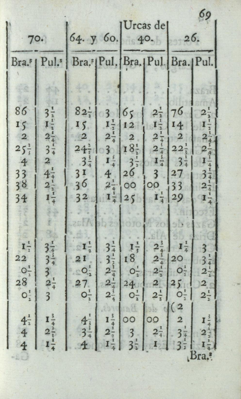
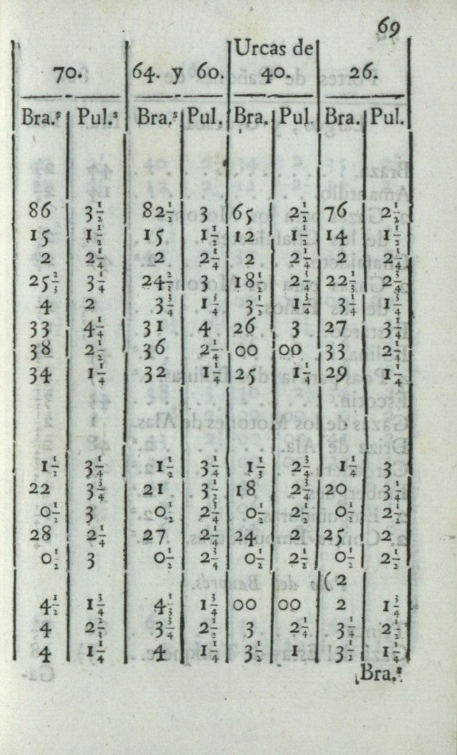
1/10,000 is fine because 100 x 100 = 10,000. Or, using the example from the second row of the table: 5 feet 3.3550 inches, and this number of digits after the decimal point requires a denominator of 10,000. But many thanks for pointing this out, and at the same time, I ask you and all readers to point out any actual or suspected mistakes to me. It is really easy to make a slip-up in this specific line of work .
-
ON THE PROPORTIONS OF MASTS, Yards, and Tops of the Ships by the Author. Chapter VI. Just as the designs of the square-rigged vessels in this book are very different from other common vessels, so too must their rigging be different, otherwise it would impede the speed of these vessels when sailing; although, in the case of the rowing vessels described in Chapters XII, XIII, and XIV, the rigging is not as different from the common style as that of the former; but the masts will be longer, in line with the design of the rowing vessel. Regarding the rigging of square-rigged ships, the author observed as a general rule that short ships should have taller masts and shorter yards; conversely, long ships should have lower rigging (for the same load capacity) and wider yards, because this will allow them to pass more easily and with less resistance the waves of the sea; considering that the wind blows almost parallel to the surface of the water; thus, if the height of the masts of long vessels were too high, they would form too great an angle with the sea and would cause the bow of the vessel to pitch more, greatly impeding its speed in strong winds. From this rule, combined with experience, we can deduce the proportions of spars of long ships; and therefore it differs little from that of the English ‘rambargi’; but the proportions of spars of these are very different from those of other types of square-rigged ships of the same Kingdom. PROPORTIONS OF MASTS by the Author. Firstly, the mainmast is taken to be the height of the hold, and that is multiplied by two, [and increased] by the breadth of the vessel at the first wale (where the author counts the breadth of the designs of his invention), and as much as the vessel is wider than 20 feet must be subtracted from the above multiplied number; and thus it gives the length of the mainmast from the heel to the [fighting] top, which is the true length of the mast; but then an eighth part is added above the top, to better support the mast with its yard above the top. THE OTHER LOWER MASTS follow the proportions of the main mast. The foremast must always be four-fifths of the mainmast; the bowsprit must be the same length as the foremast; the mizzenmast must be four-fifths of the foremast; and the smaller mizzenmast (bonaventura mast) must be four-fifths of the larger one, always counting from the heel to the [fighting] top of the mast for the true height. ON THE PROPORTIONS of the masts above the tops. The topmast, above the main mast, must be three-fifths of the main mast, from the heel to the top; thus, the [top]mast above the foremast will be three-fifths of it; and similarly, the masts above the larger and smaller mizzen masts will be three-fifths of those. ON THE THICKNESS of the above-mentioned masts. For the thickness of the main mast, take one third of the breadth of the vessel at the first wale; and one third of that third will be the thickness of the mast; and above the top it will be two thirds of the thickest part of the mast: For example, it is assumed that the vessel at the first wale is 30 feet wide; one third of thirty is ten; and one third of ten feet is three feet and four inches for the thickest part of the mast. The foremast shall be one-fifth less the size of the mainmast; and so shall the larger mizzenmast, of the foremast, and the smaller mizzenmast, of the larger; and the topmasts, at the discretion of the Master, shall be at least one-third smaller than the lower masts, in every part; the bowsprit must be slightly shorter than the foremast, again at the discretion of the master, and in accordance with the vessel's bow configuration. PROPORTIONS OF THE YARDS. The yard of the mainmast must be three times as long as the vessel is wide at the first wale. The yard of the foremast must be four-fifths of the length of the above mainyard; and the yards above the tops will be two-fifths of the length of the aforementioned yards of the mainmast and foremast, and for the thickness, at the discretion of the master as usual; and similarly for the two mizzenmasts and bowsprit. PROPORTIONS AND DESIGN of the tops. The circumference of the mainmast top must be one third of the length of the yard at most, and must be not less than by a quarter of the above circumference. The foremast top must be four-fifths of the mainmast top in every part; and the larger mizzenmast [top] shall likewise be four-fifths of the foremast [top]; and the smaller mizzenmast [top] shall be four-fifths of the larger; and the bowsprit [top] shall be equal to the smaller [mizzenmast top]; thus, for example, the yard of a vessel 30 feet wide at the wale will be three times 30 and one-third; the top must, therefore, be thirty feet at most, and the diameter of the top will be approximately ten feet, and the semi-diameter almost five feet. PROPORTIONS AND DESIGN of the masts and yards of the improved galleys. The mainmast of the improved galley is placed two-fifths parts of the length from bow to stern, leaving three-fifths from there to the wing transom. The thickness of the mainmast must be one Venetian foot and a half, and at the top and above, it will be three and a half times the thickness. The length of the said mast shall be half the length of this improved galley [measured] at the wale, called by many ‘incinta’; but for common galleys, it is measured from the ‘contuale’; and for galerone, the length of the said mast shall be four breadths, and the thickness two Venetian feet. The main yard, for the author's improved galley, must be as long as the said galley at the line, or wale, & in two pieces as usual. The foremast must be one third less thick than the mainmast, and at the top, three fifths of the greatest thickness, that is, of the foremast; and the length of its yard shall be one third shorter than the main yard.
-
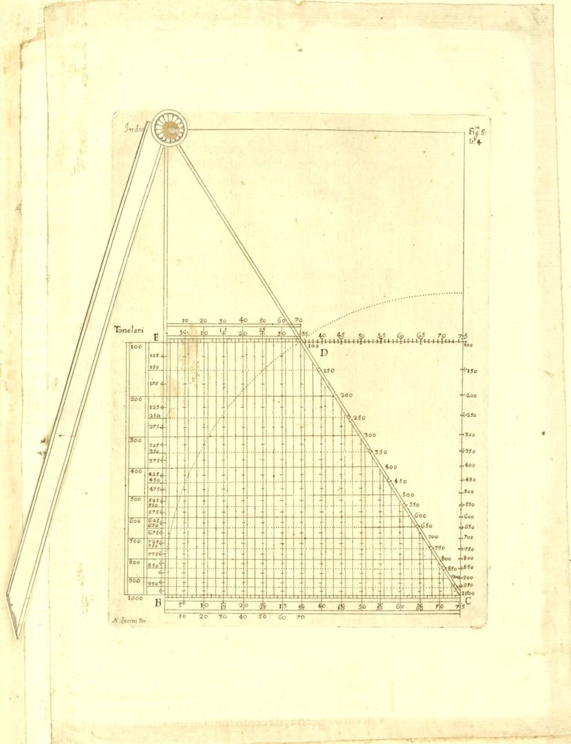
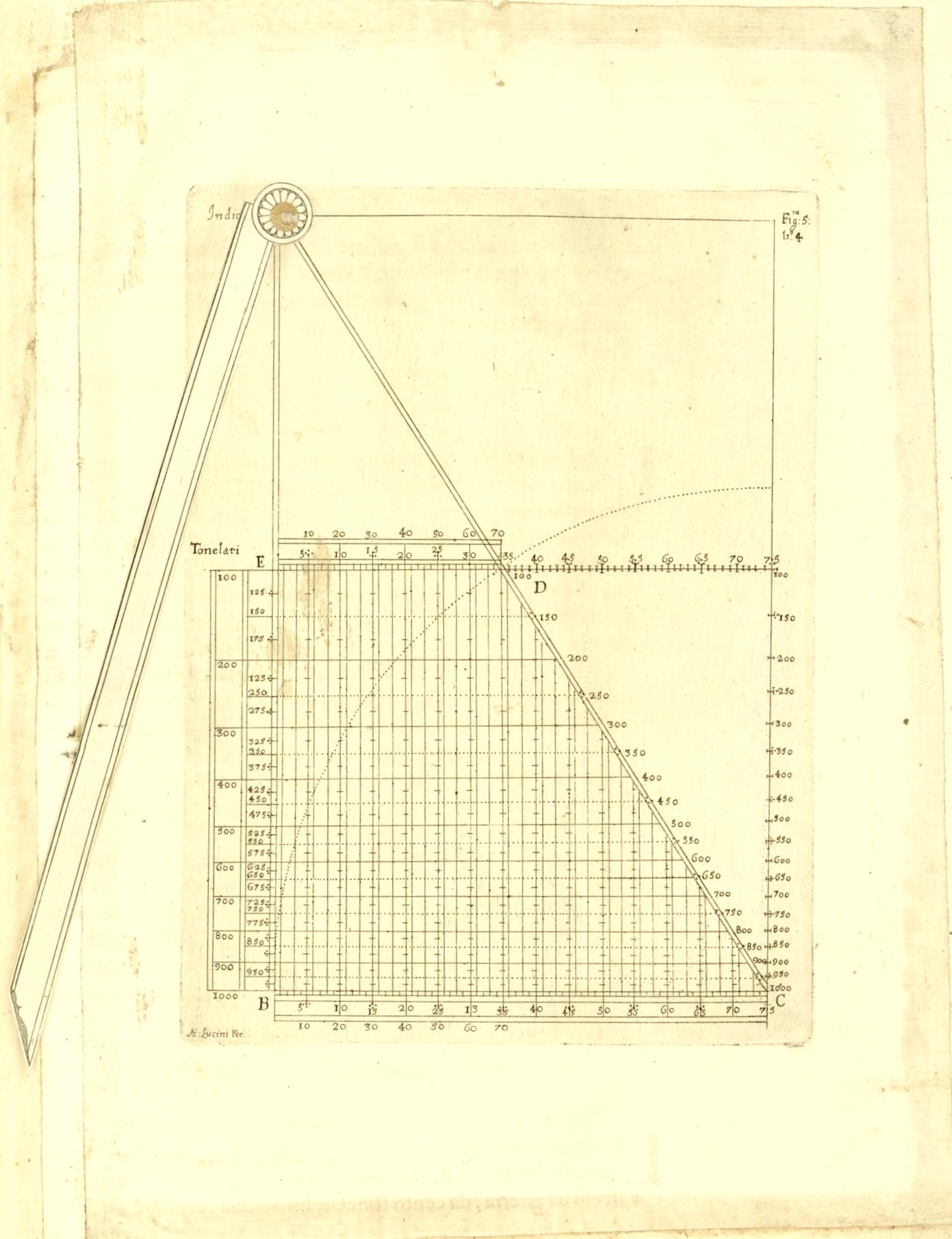
ON MEASURING THE CAPACITY OF WARSHIPS. Chapter V. The difference in calculating the tonnage of vessels is this: merchant ships are measured by how much the ship can carry in salme or tons, counting five salme per ton, and two of these [tons] make a last, since a ton is equal to 3,000 Florentine pounds and 2,500 English pounds; but the capacity of square-rigged warships is calculated by how much weight they can comfortably carry, counting artillery, ammunition, and rigging; and this produces a difference of about a quarter; so that a galleon, which can carry 900 tons of merchandise, will be estimated to be 1200 tons in war, given that these carry, on average, at least half as much artillery, ammunition, provisions, and men as those carrying merchandise of the same capacity: For example, an English Rambargio with a keel length of one hundred feet, a breadth of 33 and a third feet, and a hold of eleven and a half feet, of 55 or 60 pieces, will be approximately 600 tons in war, but in terms of merchandise, it will hardly carry 450 of the same tons. Given this, it is possible to find, by the rule of proportion, the capacity of other vessels of the same design, whether greater or lesser; but it is easier to determine this using the following tool, which yields proportionally the capacity of a given vessel. Proportional Instrument, Figure 5. DESCRIPTION AND APPLICATION. The letters ABC (the missing letter A should be at the index pivot point) show the rectangular triangle of the proportional instrument; between B [and] E, on side AB, the capacity of warships is marked, from one hundred to one thousand tons, by unequal (degressive) division, from which parallel (horizontal) lines are drawn between DE and BC, as shown in the figure; but the (vertical) lines perpendicular to the base line BC are distributed evenly: It follows that the intersection of the [rotary] index AX with those parallel and perpendicular lines yields proportionally the capacity of warships, in accordance with the given proportion and shape. For example, it is assumed that the breadth of a 280-ton vessel is 28 feet at the first wale, the length is 112 feet, the hold is nine feet, and one third, which [capacity] is found as the parallel line between DE and BC; and where the perpendicular line of 28 intersects this transverse line, or parallel of 280 tons, the index AX is rotated to that intersection and is fixed there, with the intention of finding the capacity of another vessel of the same design, 35 feet wide; and find where the index intersects the perpendicular line of 35 feet between BC and DE, from which [point] the parallel line gives the capacity of the vessel [on the scale] between B [and] E as approximately 512 tons for war. TO FIND THE CAPACITY for the first time of a limited(?) vessel ('vascello limitato'). Take the length of this vessel in feet up to the wing transom, and the breadth, including the depth of the hold; then multiply the depth by the length in English feet, or palms, and multiply the product again by the breadth; subtract one third of that sum, and disregard the last digit of the number; and thus the remaining number gives the capacity of the vessel in Mediterranean salmes, of which five salmes make one English ton of the Ocean sea, and two tons make one last. For example, it is assumed that the length of the vessel, from the bow to wing transom, is 105 feet, the width is 23 feet, and the depth of the hold is 8 feet. First, multiply 8 by 105 to get 840 feet, then multiply the width of 23 feet by the product of 840 to get 19,320. Subtract one third of this number, leaving 12,872 and a half (should be 12,880); the last figure of 2.5 (should be 0) is cut off and not counted, leaving a remainder of 1287 (should be 1288) salme for the capacity of the proposed vessel, and in tons for merchandise it will be 257 and two thirds approximately, counting five salme per English ton; but for war, a quarter more is added to the calculation; and thus we will have the capacity of the first vessel given, to be applied with the above proportional instrument [to find capacity of vessels of similar proportions]. And to load the vessel in such a way that it sails better, observe this very simple rule, which is that the keel should be level with the horizon, or parallel to the surface of the water, so that the vessel does not draw more at the stern than at the bow; and load it as close to the bow as possible, taking care, however, in the case of warships or privateers, so that they sail perfectly. And although it is difficult to do so, given that all types of vessels commonly draw more water aft than forward, in any case, by loading the vessel diligently, it is possible to greatly alleviate the deficiency and make it sail better than others of the same type and form.
-
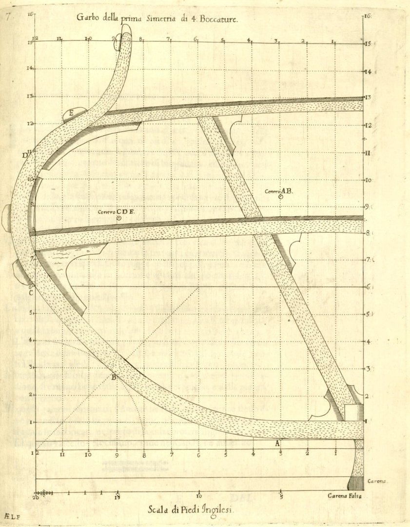
Remarks on Chapter IV: This subsection is arguably the most important in the entire chapter ‘On Shipbuilding’, especially when combined with the unpublished part of the material, as it touches upon the essence of ship design, in the meaning of hull shaping, although – realistically – it may also seem the least interesting to most ‘typical’ readers. Be that as it may, it requires a fairly extensive commentary discussing in more detail the methods of transforming the master frame mould, accompanied by explanatory graphics, which will be left until the end. For now, let us just say in general that the two principal longitudinal design lines (risings and narrowings) used and described by Dudley are the line of the floor and the so-called ‘boca’ line, which in his designs usually coincides with the run of the first wale (which in turn is parallel to the deck line). It is this very feature, apart from the three-arc construction of the frames, that determines that this is a Mediterranean method of designing. Apart from that, it can also be said now that the basic (and perhaps the only) geometric figure employed by Dudley to shape the longitudinal design lines is a “simple” arc of a circle, while the coordinates of the points of these lines for obtaining contours of individual frames could be read (measured) from the a previously made drawing, or calculated mathematically, or obtained semi-automatically using a calculating compass described by Dudley.
-
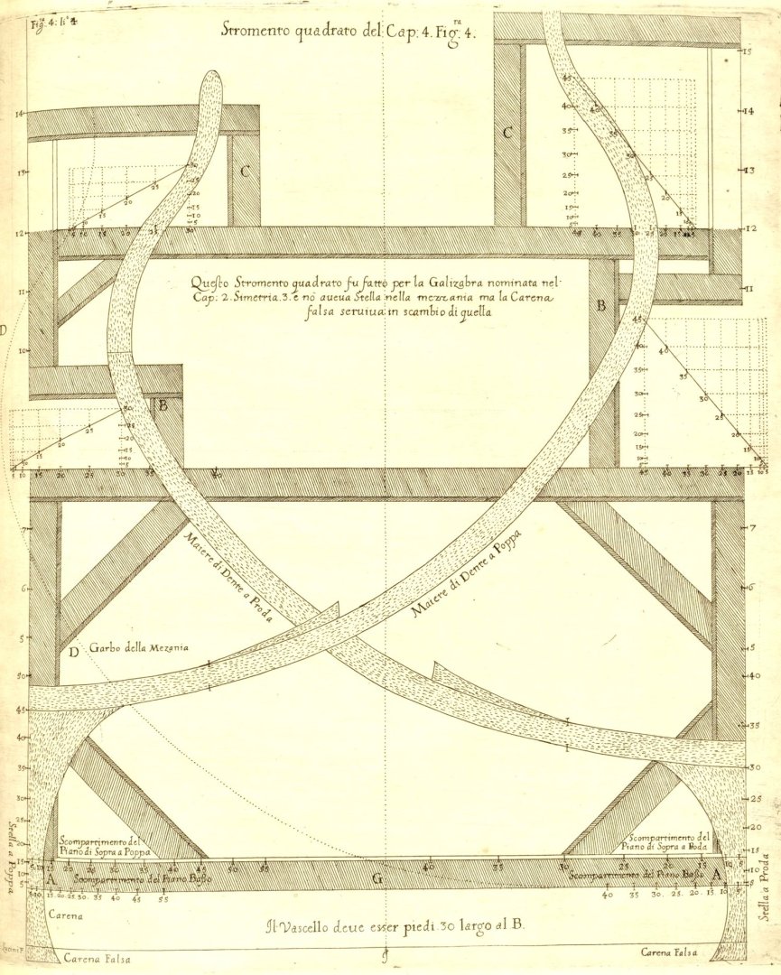
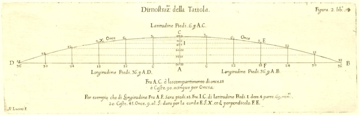
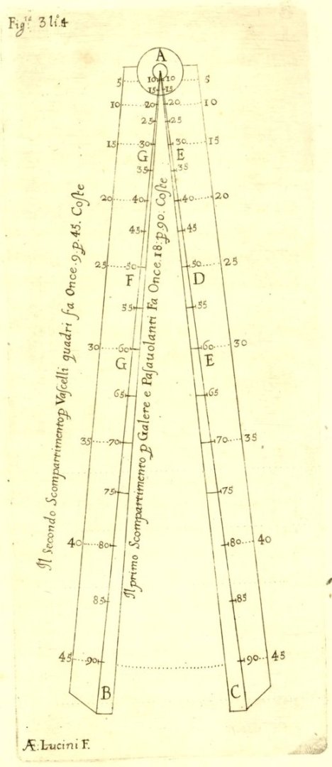
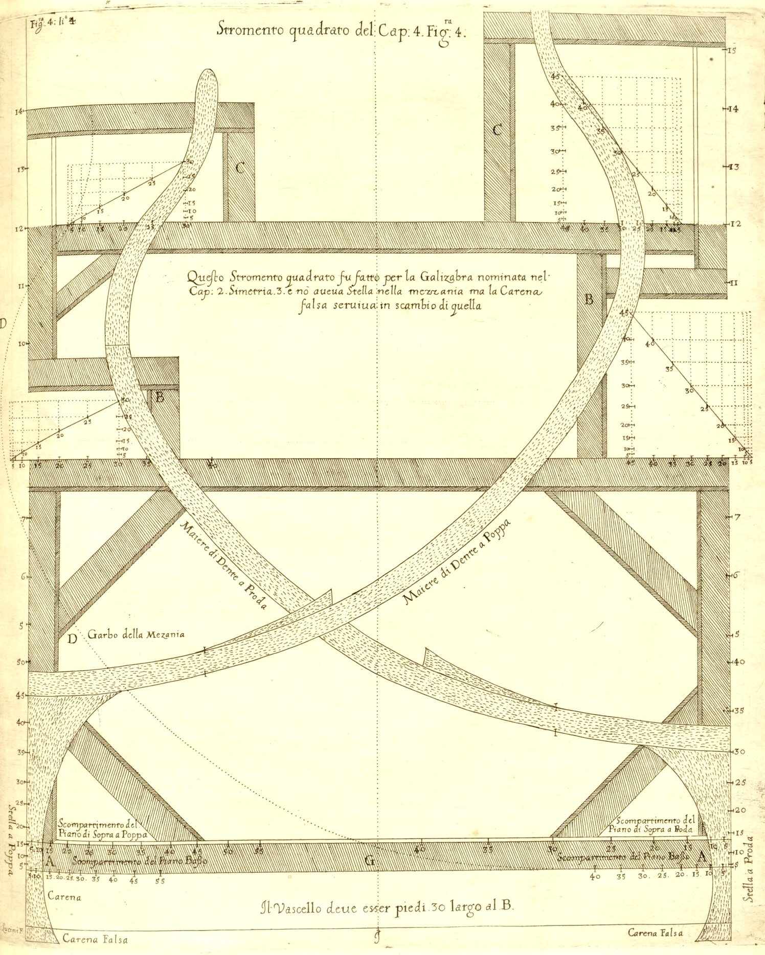
ON THE DIVISION OF THE TRUE Circle, invented by the Author to build Warships. Chapter IV. By means of the divisions that follow, the moulds, or floors, futtocks and toptimbers (which form the body of the vessel, by the rising [line of the floor]) are guided to a much greater degree of perfection than is commonly practised; and for this reason the author has calculated and invented the table that is reproduced here. TABLE OF DIVISION of the true circle Longitude in feet. Latitude in feet. Inches (10 per foot). 1/100 of inch. 1/10000 of inch. Ribs (frames) Bends (of 5 ribs) 36 6 0 0 0 90 18 34 5 3 35 50 85 17 32 4 7 12 70 80 16 30 4 1 31 0 75 15 28 3 5 89 60 70 14 26 3 0 88 0 65 13 24 2 6 25 70 60 12 22 2 2 2 10 55 11 20 1 8 16 70 50 10 18 1 4 69 20 45 9 16 1 1 49 30 40 8 14 0 8 86 50 35 7 12 0 6 50 60 30 6 10 0 4 51 40 25 5 8 0 2 88 70 20 4 6 0 1 62 30 15 3 4 0 0 72 10 10 2 2 0 0 18 10 5 1 0 0 0 0 0 0 0 Longitudine in piedi. Latitudine in piedi. Diti 10 per piede. Parti cento per dito. Minuti cento per parte. Coste 90. Once 18. DESCRIPTION AND APPLICATION. The table contains 36 feet of longitude in the first column and 6 feet of latitude in the second, and can be used for any greater or lesser number of longitude and latitude, using [instrument shown in] Figure 3. In the third column, each foot is divided into only ten parts, to facilitate the calculation of the Table with perfect numbers; and it serves the operation sufficiently, and without considerable difference, as if the foot were divided in the usual way into 12 inches; & each inch in the fourth column is divided into one hundred parts; & each hundredth part of the inch is subdivided into one hundred minutes in the fifth column; the sixth shows the number of ribs of the vessel, up to ninety ribs; and the seventh column presents the bends, which are eighteen, counting five ribs per bend. The application of the Table follows; for example, given that the longitude is 24 feet in the first column; opposite that number, in the second column, it will give two feet for the latitude, and six inches in the third; and 25 parts of a hundred in the fourth column; and 70 minutes of a hundred in the fifth; if the ribs are 60 as per the sixth; with 12 bends in the seventh column. This example, for the execution thereof, is demonstrated in the following figure, which has its basis in the preceding Table. Figure 2. DESCRIPTION The semi-chord AB will be 36 feet in longitude, and the latitude will be 6 feet for AC, and the 18 bends of the ribs as per the seventh column, [and there] will be the right angles between ABF, AC & EC (should be EF instead of EC); and so every perpendicular line between the chord ABDF and the arc BCDE gives the quantity of the division up to one hundred minutes per side. THREE OTHER INSTRUMENTS by the Author, to be used with the division of the true Circle, with the Table, for building ships. The first instrument is in the form of compass, to be opened to the number of bends given, and the width and distance limited by the plan and profile of the vessel to be built, in accordance with Chapter VIII and the others up to Chapter XIV, and thus these compasses will give the orderly division of the bends, and ribs, conforming with the previous table, by applying to the ribs of the vessel its width and height, and also the rising [line of the floor]. Compass, a circular scale in two modes, one of ten bends for square-rigged ships, the other of seventeen or eighteen bends for ‘Galeroni’, or improved galleys, and ‘Passavolanti’. Figure 3. DESCRIPTION The two legs BC and AC of the first instrument must be approximately three cubits long; one [side] divided [progressively] into ten bends, for the square-rigged vessels of Chapters VIII, IX, X and XI, and the other [side] into seventeen bends, for the rowing vessels of Chapters XII, XIII and XIV. Thus, the compasses ABC are opened at the required distance to be divided, and [this] at the given number of bends and ribs; and holding the instrument at that setting, the division is made, with the same numbers always opposite, in accordance with the previous table; for example, the number of bend 30 at G corresponds to 30 at E, and bend F corresponds to D, and similarly for the other bends, and they yield the division that must be made. ON THE SECOND TOOL in the form of a ruler. This must be at least as long as the vessel will be wide at midship at the first wale, and will be divided in the usual way, to give the width of bends and ribs at the bottom of the first wale, that is on the edge of the ruler, in accordance with the plan drawn in the figures in Chapters VIII to XIV, which show how the width of these ribs must decrease towards the bow and stern, at the first wale mentioned above; and the division is known by means of the previous figure, and for as many bends and ribs as one may desire; and therefore it is so easy that it is not necessary to produce the figure of the ruler. ON THE THIRD TOOL in the shape of a square. Figure 4. This instrument is made of wood joined together, & in square shape, for half the greatest breadth of the vessel, and will be divided, by means of the first instrument, in the manner shown in the figure, to give the width & height of the ribs & bends, with the help, however, of the [master frame] mould, applied by means of the figure; and thus every skilled master builder can understand the author's intention well and put it into practice, and it is a very curious and useful invention, not deviating from the design of the plan and profile, which is provided in Chapter VIII to Chapter XIV. Other requirements concerning the reduction (transformation) of the ribs, and their thickness and reinforcement, by [the help of] the ribbands and battens, are common knowledge and well understood by master builders, and are therefore omitted here, as the author does not wish to deal with ordinary and commonplace matters in this treatise, as has been noted on other occasions. Indeed, by means of the third, square instrument mentioned above, it is possible to mould the sides of the vessel from stern to bow, and throughout; which thing cannot normally be done, except between the two quarter frames; and therefore the vessel cannot be kept steady, as it should be; and by means of the aforementioned square, it will always be very steady, the mould being well made and applied; and it is a great secret, even though the author deals with it sparingly; albeit it is sufficient for intelligent masters to understand it by means of the figure, it cannot be understood by the ignorant, because they will never fully understand the application of this invention by means of the figure alone. Of note still that the author has employed the square instrument described above to design ships, he has done so both in the construction of rowing galleys and square-rigged sailing ships and high-sided vessels.
-
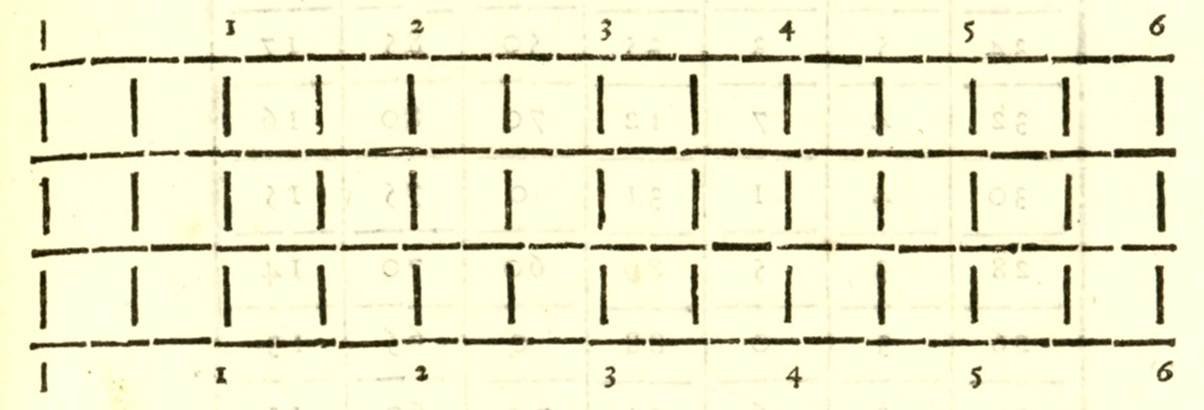
ON THE SCALE OF FEET AND PALMS, which must be used in the construction of the preceding designs. Chapter III. There are three scales, which can be best used in the building of warships mentioned in the previous chapter. The first scale must be in English feet, because it is best suited to the construction of square-rigged vessels, each foot being divided into 12 inches, and each inch into 8 or 12 parts. The second scale will be Genoese palms, three of which make two feet, and six English inches, which make one cubit, consisting of three palms, as usual, and applies only to the seventh design of the ‘Passavolanti’, as [presented] in Chapter XIIII (XIV), and to common galleys. The third scale will be a few palms longer than the second, applied by the Author to the construction of the fifth and sixth designs from Chapters XII and XIII, and three of these palms per cubit make two feet and seven English inches, and each of the Author's palms corresponds to 12 Venetian inches, of which 16 make one of their feet; however, each palm is divided into 12 inches, and each inch into 12 parts: Hence it follows that the two scales of said palms are based on the English foot, as above; and therefore it will suffice here to make the perfect length of an English foot divided into 12 inches; five of which feet make a pace, and a thousand of these paces make a mile, and 60 of these miles make a degree of the great circle, according to the calculations of English sailors. Therefore, the scale of half an English foot is divided into six English inches, and each inch into eight parts; and this can also serve as an explanation of the following first figure of the English foot. For the division of the half foot into six inches, the length of three inches gives the fourth part of the same foot; and six inches, the half, and nine inches, three quarters; and four inches, the third part; and eight inches, two thirds of the said English foot, two of which make a Florentine fathom less half an inch, approximately.
-
Ah, this is perhaps a bit out of order, however, since the issue has already been raised, at least some graphics with a few unpublished master frame designs by Dudley can now be shown, which demonstrate that the ships were indeed designed by Dudley with more than just one operating draught in mind. For convenience, these levels were synchronised with the height and width of the wales. As for the proportions of the ships envisaged by Dudley, it is true that some of his designs are, in some respects, rather unusual proposals for their time. But this effect also results from the close, rather complex relationship between the various dimensions of the ship (together with the simultaneous consideration of various design constraints), to enable it to sail or row effectively. We may come back to this later, yet, in essence, it is the design method that is most important here, rather than the proportions of Dudley's designs.
.thumb.jpg.3c3a064878b3190f6150aa62b6b07da3.jpg)
-
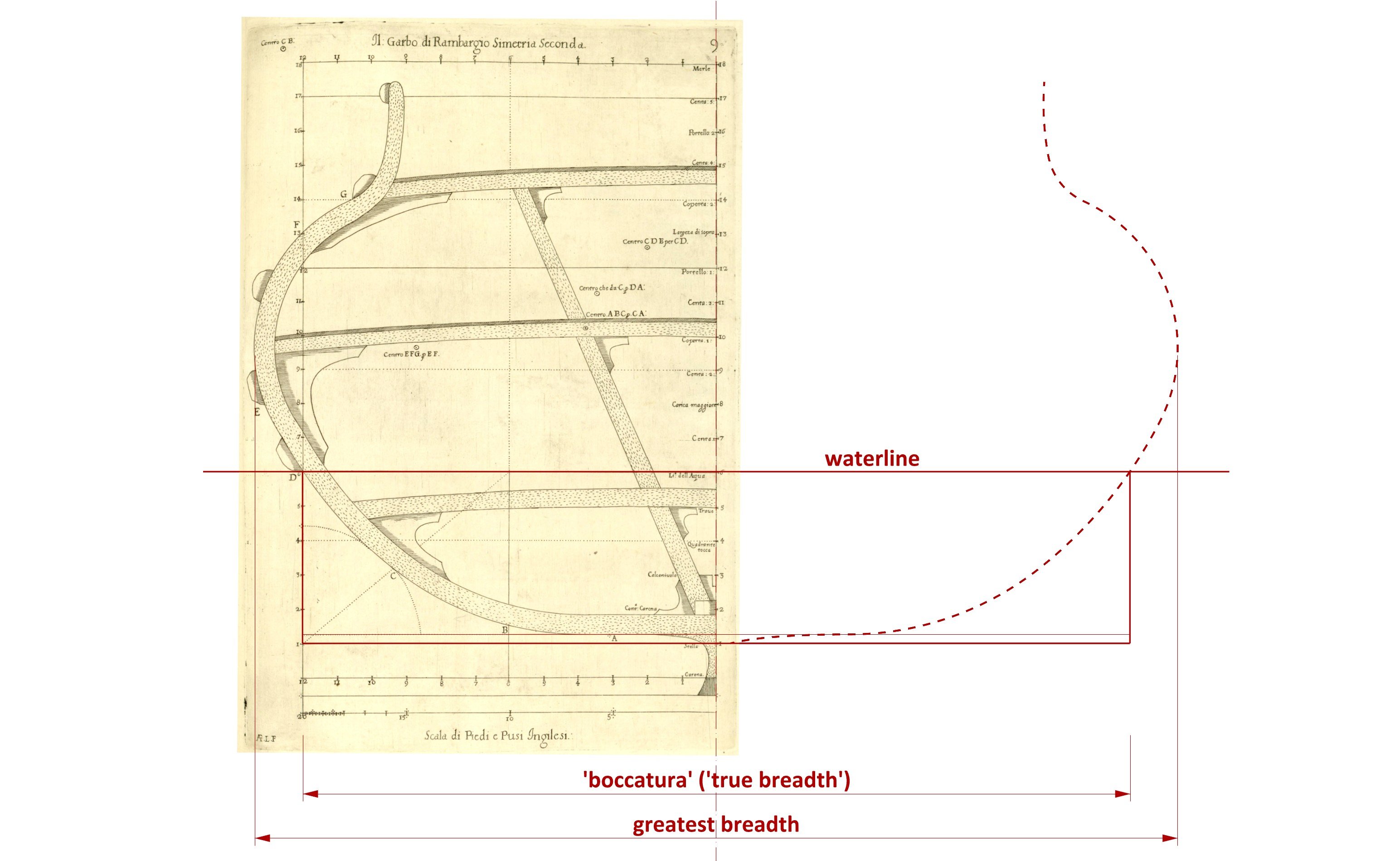
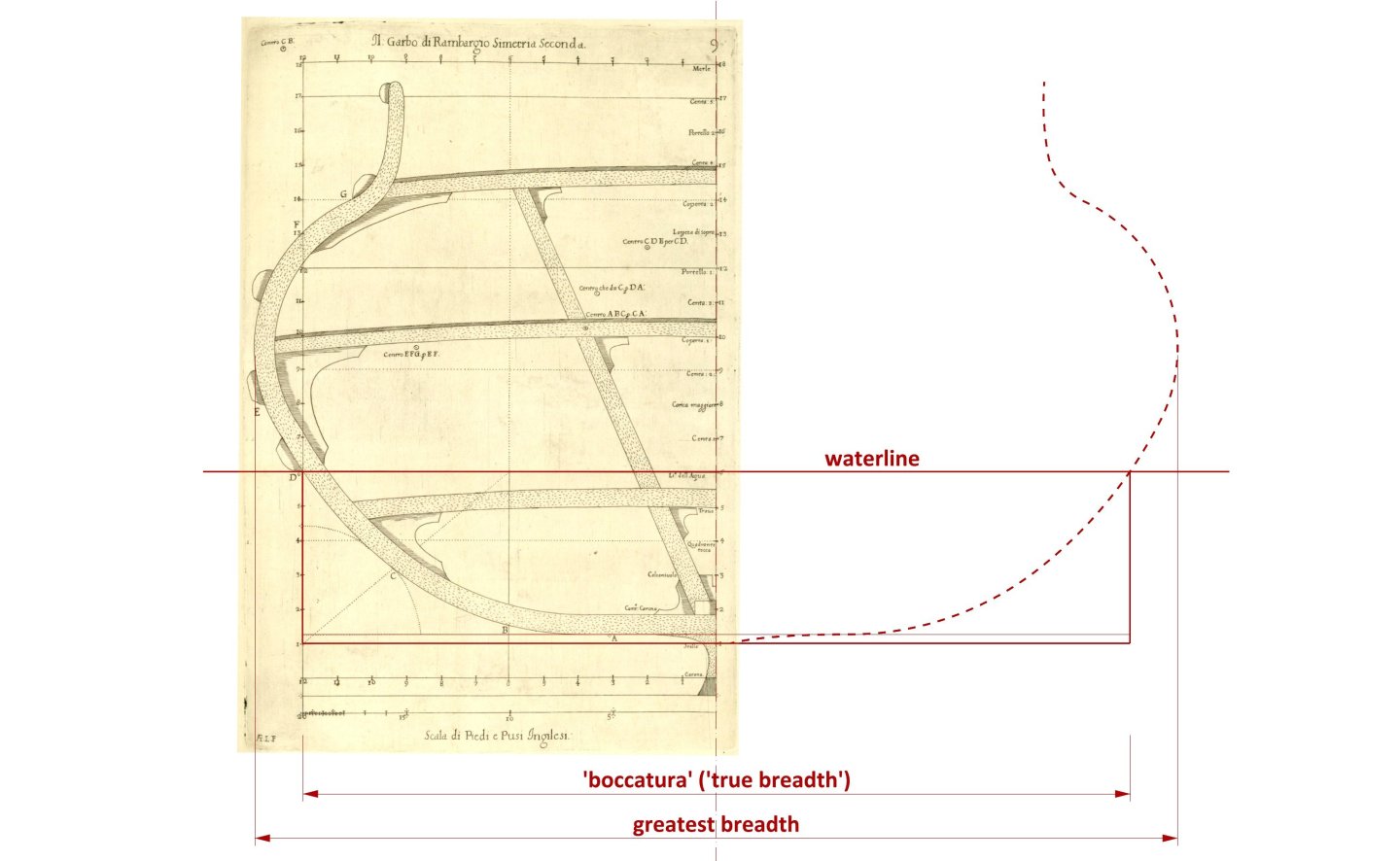
Remarks on Chapter II: At the outset, it should be emphasised that a particular design method or design system (or, in modern terms, a parametric model) should not be equated with the specific proportions used in a particular design (or, in modern terms, a specific set of parameters entered into such a parametric model), which, unfortunately, is quite common among various authors in this field. In other words, a ship with the same proportions can be designed using different methods, or conversely, ships with different proportions can be designed using the same method, simply by modifying the design parameters. And, at least in a geometric sense, the size of ships, i.e. measured in absolute units of measurement such as feet, cubits or metres, is a completely separate issue. That said, it should be noted that Dudley's 'inventions' do not consist in the discovery of some new, previously unknown design method, but merely in ‘playing’ with proportions, and in his specific case, primarily in a quite significant increase in the relative length of ships, as it seems, well above the customs accepted at the time. And so, the essence and main criterion distinguishing his seven ‘inventions’, i.e. proposals for seven different types of vessels, is well reflected in the following unpublished sketch taken from a handwritten batch of material: Although his designs of different types of ships could have individual, varying breadths (and also generally vary in size), in the above sketch they have all been scaled to a single, common width, making it easy to see the difference in the relative lengths of these vessels. Dudley's shortest design is for a galleon four breadths long, and the longest is for a passavolante 10 breadths long. The basic unit of measurement used for further calculations of the main proportions of the ship is the breadth of the hull, quite consistently referred to by Dudley as “boccatura” in the publication, and in handwritten notes also as, for example, “true breadth” at the level of “true waterline”, and similarly (in Italian and in English). Indeed, in accordance with the Mediterranean method or tradition, this breadth is not measured at the widest part of the hull, but at the height of the so-called 'boca' line (at midship), which in Dudley's designs, to simplify now somewhat, generally coincides with the lower edge of the lowest wale and at the same time with the swimming line, and the greatest breadth is hardly mentioned at all in the whole publication. A typical case can be clearly illustrated by one of the published diagrams:

-
ON THE SEVEN DESIGNS in general of Warships invented by the Author. Chapter II. The first design is shown and described in the figures in Chapter VIII below, of an improved galleon long four breadths along the first line, or wale, which sports two and a half decks, with the gunroom, and will carry eighty pieces, in the manner described in Chapter VII. The author had a 300-ton version of the same design built for himself, carrying 30 pieces, in which he sailed as a general to the Indies in 1594 with other vessels, at his own expense (for comparison, according to the calculation method provided by Dudley, the capacity of his published design is 1000 ton). The second design is of ‘rambargi’, presented in Chapter IX, long five breadths along the first line, or wale; one of which will carry 90 pieces, with the restrictions described in Chapter VII, and they are faster than galleons; and these resemble the longest ships of the Royal Navy of England. The author had one of this type built for the Most Serene Grand Duke Ferdinand I, of about 600 tons, named S. Giovanni Battista. In any case, it carried 60 large, reinforced pieces and proved its worth against the Turks. The third design, described in Chapter X, is of a ‘galezabra’ long six breadths along first line, or wale, which carries two decks and a third, with the gunroom; and this is a vessel even faster than the ‘rambargi’, and is very formidable in fighting from windward with the force of its artillery, and will carry 90 pieces, those described in Chapter VII, with others reinforced [guns]. Of these ‘galezabres’, the author had one built for the Most Serene Grand Duke Cosimo II, not exceeding 300 tons; although it carried 40 good pieces, it was a very fast and very stable vessel. The fourth design is a square-rigged vessel, named a frigate by the author, seven breadths long, with the entire stern, and its proportions can be observed in Chapter XI, and carrying 50 pieces [described] in Chapter VII. And the author built as a test a small vessel, like a ‘pinaccio’, of this design for himself in Livorno in around 1608, and it proved to be very fast and handled well at sea. He had another vessel of the same design, of about 140 tons, built when he went to the Indies, named the Little Bear, commanded by Captain Monck, an Englishman, a relative of the author and his vice-admiral. The fifth design is of rowing vessel, being an improved ‘Galeazza’, called by the author ‘Galerone’ or ‘Galeratone’; which is much more manoeuvrable than the galeazze, and can be dismasted and propelled [by rowing] very well, which the large galeazze cannot do. The Galerone has length of eight breadths along its line (wale), as [shown] in Chapter XII, and can carry 50 carriage cannons and 20 hail-shot guns (‘petrieri’). The author had one of this type built, not so large but longer, for the Most Serene Grand Duke Cosimo II, named Galerata by its inventor, which carried 32 carriage pieces and 20 ‘bombardine’ and moved very well, especially under sail. These are exquisite vessels for sailing and for fighting in battle in place of galleys, and the cost is little more than that of a galley, except for the artillery. The sixth design is a nine-breadth long improved galley by the author, [decribed] in Chapter XIII and named by him ‘Galeratina’. He had one of these built for the Most Serene Grand Duke Cosimo II and named it S. Cosimo. It proved to be the fastest and best-conditioned galley in the Mediterranean, as is well known. and this one did not carry guns on its sides, but rather eight ‘bombardine’ on each side, and two more guns than usual at the bow: These, however, are good vessels for the course. It was the Galera Padrona. The seventh design, of the length of ten breadths along the line (wale), named ‘Passavolante’ by the inventor: Its proportions are shown in the figure in Chapter XIII, and one of these was built for the Most Serene Grand Duke Cosimo II in a similar manner. Therefore, the knowledgeable demonstration follows to manufacture the seven designs mentioned above.
-
Strange as it may sound, the important and extremely interesting chapter Della Fabbrica di Vascelli (‘On Shipbuilding’) from Robert Dudley's larger work, Dell'Arcano del Mare (‘The Mysteries of the Sea’), has so far been largely overlooked by authors of modern works on this subject, and has probably not even been retranslated into the native language of the author of this work, or at least no such translation has been published so far to my knowledge. This can be considered a serious oversight, especially on the part of the academic community, as this very chapter, together with its unpublished part, is at least equal in terms of its substantive value to other works on shipbuilding from this period, such as Baker's Fragments of Ancient Shipwrightry, an anonymous manuscript dated around 1620, or the so-called Newton manuscript from the second quarter of the 17th century. What is more, Dudley's complete account, graphic par excellence (notably with its unpublished, handwritten part), perfectly complements the above-mentioned works and, in addition, greatly facilitates their proper understanding, especially since they have been misinterpreted by the academic community and various researchers through the unauthorised backward extrapolation of later English sources of this kind, such as the Anthony Deane's work from 1670 or William Sutherland's from 1711, which, together with other mistakes, inaccurate analyses and misinterpretations in this field, has had the unfortunate effect of creating modern concepts that dramatically distort the evolution of naval architecture during this period. Although Dudley's work was published as late as 1646–1647, both his biography and the information contained in the publication itself indicate that Dudley uses and describes the method of ship design that was used in England around 1600, which he must have learned there before emigrating in 1605. This is the Mediterranean method, introduced in England around the middle of the 16th century, marked by a three-arch frame construction and the specific transformation of master frame mould, guided by the so-called “boca” line (instead of the maximum breadth line). Over time, around the middle decades of the 17th century, this system evolved into a more advanced form, which can already be described as genuine English design. At least for now, I intend to present a full translation of the chapter ‘On Shipbuilding’ (without focusing on linguistic perfection, if only because of the archaic, crazy syntax of the original Italian text, but rather on a factually correct and comprehensible rendering of the meaning of the statements) along with reproductions of graphics taken from both the printed publication and some unpublished ones (many thanks to @DonatasBruzas for pointing out the latter), as well as supplementary comments, explanations and my own illustrations where necessary and possible. In total, approximately 73,000 characters, or 40 standard A4 pages of text. Let’s start… THE MYSTERIES OF THE SEA, OF THE DUKE OF NORTHUMBERLAND BOOK FOUR ON SHIPBUILDING by Design in general, of the invention of the Author. Chapter I. The Naval Architecture discussed in this book was invented and put into practice by the author himself in seven different designs of warships. The figures and proportions of these are shown in Chapters VIII to XV, with individual lines, profiles and moulds, with explanations and other necessary details. So that the author's aim does not prove vain and superfluous, having dealt in the preceding Third Book with the ordinance of forces, the power and strength of ‘rambargi’ (rowbarges), ‘galezabre’, frigates and other vessels, he will now demonstrate the true science of design, so that everything can be put into practical execution. And because words do not fight, but what has been promised will be produced in effect, & in practical action; demonstrating how skilled masters (who also understand something of mathematics) can build by design the vessels referred to in the following chapter, without the inventor himself being present; considering further that the hope of a victory at sea, in winning the day, depends mainly (thanks God) on the strength and quality of vessels that are well constructed and well disciplined, according to the instructions in the preceding Chapter. Otherwise, it would have been highly impertinent of the author to criticise the shortcomings and failings of other warships without offering any remedy to improve them. However, he deemed it expedient, for the reputation of his maritime Mysteries, to show in the best possible way the naval architecture of the construction of the following vessels; and all the more so because in this way a great prince can be victorious against the common enemy of Christianity, not only at sea but also on land, by means of maritime assistance; and the reason and cause for this is sufficiently demonstrated by the examples given in Chapter XV of the preceding Book.
-
Hello, In the hope of making your decision easier and perhaps giving you some confidence in how to proceed with the timbers at the bow, it can be said that these plans are structural reconstructions, so they can certainly be reinterpreted in various ways. For example, in addition to the solutions you have already mentioned (or shown), others can be added: the first frame (I) can simply be made perpendicular to the keel, rather than canted (as the frame XV at the stern), or if you still prefer this frame to be canted, you can make the construction simpler and do this by slightly tilting the flat first floor piece (instead of making it V-shaped when viewed from above). It is clear that these boats were individually built in different ways by different builders.
- 139 replies
-
- 4
-

-

-
- ancre
- Bateau de Lanveoc
- (and 2 more)
-
I see. Perhaps you have a friend who could be able to download these pages for you. It's only a few hours' effort. Alternatively, you can buy a hard-copy reprint, where the texts, including the tables, are already transcribed. No need to download and print anything.
-
Using the link provided, I accessed the library website, found the desired page, and downloaded it. This is rather pointless, as you can fortunately do all of this yourself, already without any additional help. Good luck.
-
-
Take a look here (entry #3):
-
Ah, yes, the Lomellina case… Fortunately, for an exhibition model, unlike a full-scale floating replica, stability issues are no longer of the utmost importance in the sense that any mistakes or misinterpretations will at least not lead to some kind of costly disaster. You wrote earlier that you have direct contact with people who are involved in researching the Lomellina wreck, and that you receive materials from them regarding this wreck. Are you perhaps aware of any other attempts to reconstruct the ship's shapes besides those presented or recalled in the 2023 paper attached below? Frankly, for certain reasons I'm not personally thrilled with these attempts and its results, but more importantly, I see that you also decided not to follow the published reconstruction and are creating your own interpretation. Guérout Max, Frabetti Beatrice, Castro Filipe, Revisiting Lomellina, 1516 – The Hull Shape, 2023: Guérout Max, Frabetti Beatrice, Castro Filipe - Revisiting Lomellina, 1516 - The Hull Shape - 2023.pdf
-
Hi, If I may, I'll try to start (hopefully) jokingly. These and similar thoughts could indeed quite easily end up like this (most interesting from the 30th second): But more seriously, in addition to dozens, perhaps hundreds, of different plans from the period, quite clear (written) indications on this matter can be found, for example, in the shipbuilding manuscript from around 1610 by Lavanha or the so-called Newton manuscript from the first or second quarter of the 17th century. But perhaps this is most spectacularly and instructively demonstrated by Robert Dudley in his work (manuscript) from around 1636. The descriptions of the individual levels in the diagrams below (transcribed in red) practically speak for themselves and probably don't even need any further commentary. Perhaps except that this specific material has almost certainly never been used or maybe even noticed by anyone before.

-
Mary Rose 1511 — the epitome of the Northern tradition
Waldemar replied to Waldemar's topic in Nautical/Naval History
Quite possibly the Northern European Late Middle Ages, with its Hanseatic cogs and other cog-like vessels, Scandinavian ships, earliest carracks, etc., and all their somewhat later derivatives, also needs attention, because this period is in fact as conceptually unexplored as the early modern era has been neglected so far. Funnily enough, various researchers are able to carry out really complicated hydrostatic and hydrodynamic calculations, as well as expensive experiments of various kinds, including real-scale sailing, except for the “ trifle” that it is still unknown how these ships were actually designed to satisfy the results of all those modern scientific tests and calculations . As a result, it is simply not possible in the present state of knowledge to draw some conclusions of a more general nature, for example to the extent you ask. -
Mary Rose 1511 — the epitome of the Northern tradition
Waldemar replied to Waldemar's topic in Nautical/Naval History
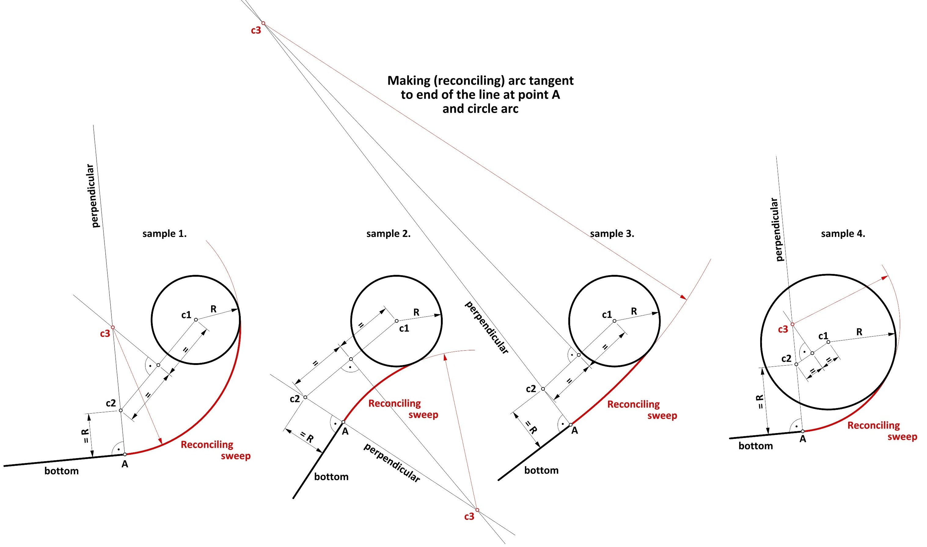
It occurred to me later that one could still show a geometrically rigorous way of determining the reconciling sweep tangent at both ends (that is, to bottom line on one side and to lower breadth sweep on the other). Although the method is extremely simple, it is highly doubtful that it has been used in practice, and especially at actual scale on the mould loft, as can be seen particularly well on sample number 3, where the auxiliary lines extend far beyond the contour area of the frame. The method using a flexible instrument, shown previously in the entry #40, is by far the preferred one, not only because it is hassle-free, but also gives excellent results in terms of the precision of the contours obtained, and this is true even allowing for the minor inaccuracies of handling such a flexible instrument. Be that as it may, below is a method employing formal geometry: 1. make a perpendicular to the line of the bottom at point A, 2. mark point c2 on this line at a distance R from point A, 3. connect points c1 and c2 with a line, 4. find the midpoint of the line c1–c2 and make a perpendicular at this point to line c1–c2, 5. the intersection of the two perpendicular lines (described in steps 1. and 4.) yields point c3, which is the centre of the reconciling sweep.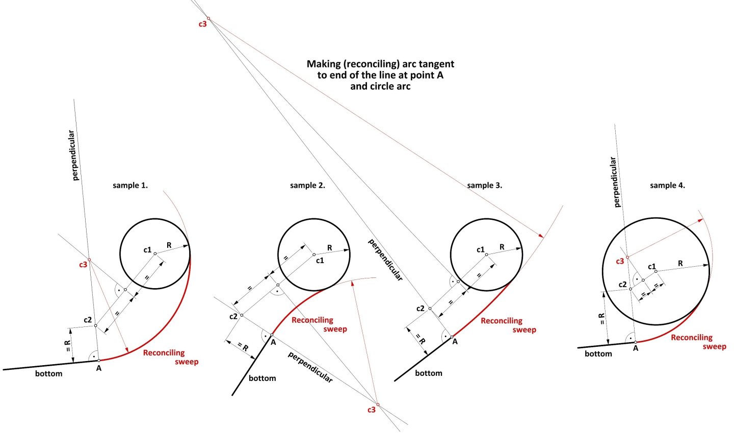
-
The fact that the joinery is anything but sloppy (or perhaps better: irregular) does not mean that the design itself was also careless. Let's take, for example, the buildings of the Incas, the pyramids of the Egyptians or Neolithic Stonehenge. Despite the considerable irregularity of the stone components used, astronomers still find remarkable precision in the assembly of these structures. The same is also perfectly true today — aesthetic aspects aside, it actually does not matter whether the floor in flats and offices is made of boards or tiles of varying dimensions, as long as it is level and sufficiently even. So why waste a good material? The oldest shipbuilding manuals very rarely mention the width of the planks, if at all, as opposed to their thickness and sometimes the minimum length required for more "strategic" components of the structure.
-
Well, fine, now that it's “all” cleared up, I at least have a smooth excuse not to spend a perverse amount of money on the decent quality copies of source material needed to prepare free presentations after all. I'm off back to my favourite 16th and 17th century (and European archives ).
-
Ah, you may have spoiled my surprise, but perhaps that's for the better, as the further fate of this very venture is quite unclear indeed. On the one hand, you might have had it easier, as we have discussed the issue privately before, yet, on the other hand, with your watchful eye for shapes you yourself must also have noticed the striking resemblance to French light craft of Louis XIV's time, such as the frigate l'Aurore 1697 (body plan shown in the thread on the Mary Rose 1511). Now, I would still like to say that people, while attempting similar analyses, usually focus on comparing dimensions, which is completely missing the point. After all, absolute dimensions, just like many of the proportions, are simply determined by a kind of circumstances which have little in common or being quite independent of design methods, as you pointed out above.


.jpg.d59764d6a2b8c1960f56e1b32f6d986e.jpg)