.jpg.6c90d67e7e9071af590f4d4a2a8bc908.jpg)
Waldemar
-
Posts
1,003 -
Joined
Content Type
Profiles
Forums
Gallery
Events
Everything posted by Waldemar
-
.thumb.jpg.c6343966b029e7941df5b987d129aac6.jpg)
Mary Rose 1511 — the epitome of the Northern tradition
Waldemar replied to Waldemar's topic in Nautical/Naval History
It is quite possible that in this way we are entering the realm of speculation as to events that may have actually taken place, but the idea itself is most pertinent, because this is exactly how things were done, that is, a set of values defining the geometry of a ship was written down numerically, which in effect quite unambiguously recorded the features of a particular design and later made it possible to reproduce it faithfully. Provided, however, that the design paradigms, i.e. the design methods with their specific handling procedures, were identical. This is also a good opportunity to complete such a basic list found at the beginning of the thread (entry #4) and to group together in one place all, hitherto somewhat scattered data of this kind. Slightly reiterating here, assuming that the English shipbuilders followed exactly the same design methods as their French counterparts, and that these were as interpreted above, for a faithful reproduction of the underwater part of the hull they would have needed the following set of data from this alleged agent: Mary Rose (1511) – dimension set General dimensions Breadth outside planking 40 feet Breadth inside planking 39 feet 4 inches Length between posts (at 3rd deck level) 3.5 x breadth outside planking 140 feet Length between rabbets (at 3rd deck level) 3.5 x breadth inside planking 137 feet 8 inches Draught at midship (without keel) 1/10 x length between posts 14 feet Keel assembly & lengthwise division Forward rake 2/13 x length between posts 21 feet 6½ inches (21.54 feet) Radius of the stempost 3/4 x breadth 30 feet Aft rake 1/13 x length between posts 10 feet 9 inches (10.77 feet) Height of sternpost height of 1st deck at midship (10 feet) + height of 2nd deck at midship (7 feet) + height of 3rd deck at midship (8 feet) + rising of 3rd deck aft (6 feet) 31 feet Keel length 10/13 length between posts 107 feet 8 inches (107.69 feet) Placement of double master frame 6/13 of the hull length (fwd) 7/13 of the hull length (aft) Placement of quarter frames 3/13 of the hull length (fwd) 10/13 of the hull length (aft) Risings and narrowings — Line of the floor Deadrise at midship 6 inches Rise forward 6 feet Rise aft (height of tuck) 12 feet Breadth of the bottom at midship 1/4 x hull breadth 10 feet — Line of the breadth Height above waterline at midship 3 feet Rise forward 5 feet Rise aft 7 feet Reduction of the breadth at quarter frames 1/6 (fwd) 1/5 (aft) Transom length 4/9 x breadth ca. 18 feet Quarter frames Radius of sweeps of the bottom 6 feet (fwd) 10 feet (aft) Radius of lower breadth sweeps 12 feet (fwd) 12 feet (aft) Mainmast position 1/2 x length between posts -
Mary Rose 1511 — the epitome of the Northern tradition
Waldemar replied to Waldemar's topic in Nautical/Naval History
Thanks a lot, that's one of the very reasons of this presentation . It is also worth remembering that seagoing ships sporting short hulls must have sharp underwater hull lines. -
Mary Rose 1511 — the epitome of the Northern tradition
Waldemar replied to Waldemar's topic in Nautical/Naval History
Thanks, yes that is an otherwise pertinent question. Admittedly, there is a corresponding specialised function in CAD software and everything is done in a flash, however, in actual size, or even drawing manually to scale, it is also or can be trivially easy. Please see the diagram below. I have drawn a simple instrument there, for example a wooden or plastic one. Basically it's a flexible strip, and it has two segments. The wide, unbending segment of it is applied to the straight lines of the bottom (or to the straight dashed lines in the diagram if the curves of the bottom are arcs), and the remaining thin and flexible part of it is then bent until it reaches the lower breadth sweep. Ideally, the bending force should be applied roughly at the spot of the expected touch point with the lower breadth sweep. Edit: on this issue see also entry #75. If you still have any issues, please go ahead.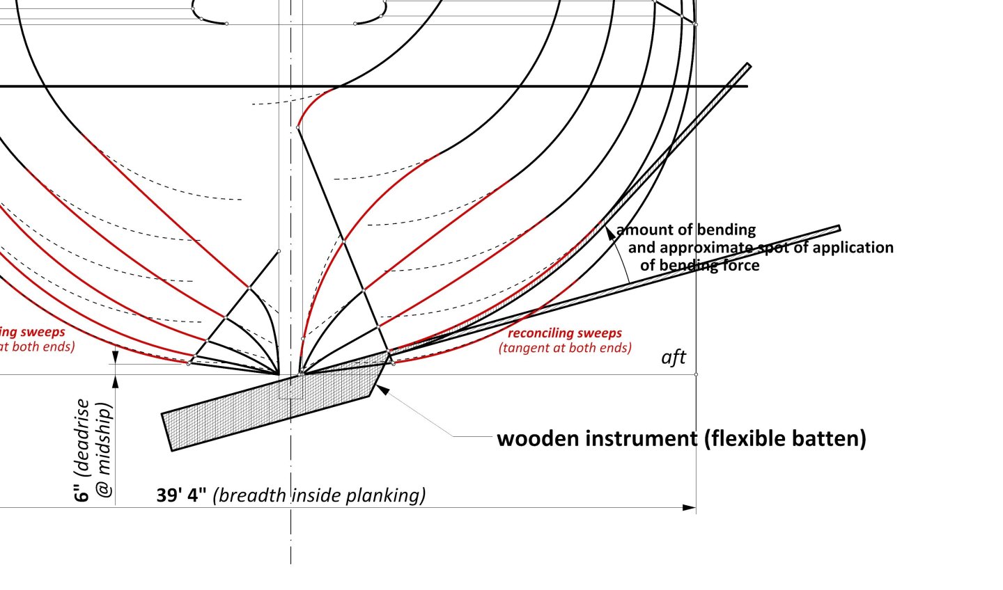
-
Mary Rose 1511 — the epitome of the Northern tradition
Waldemar replied to Waldemar's topic in Nautical/Naval History
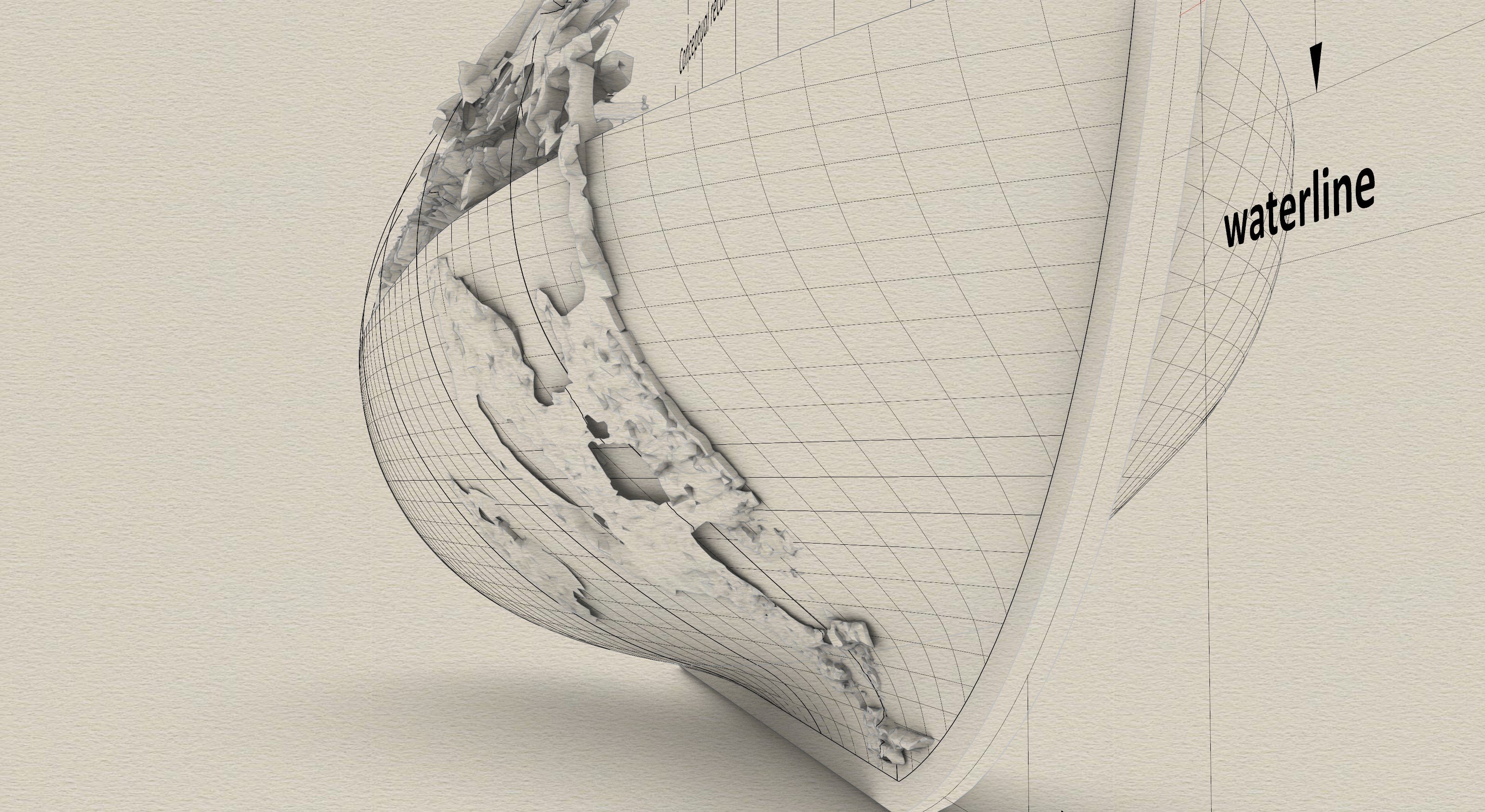
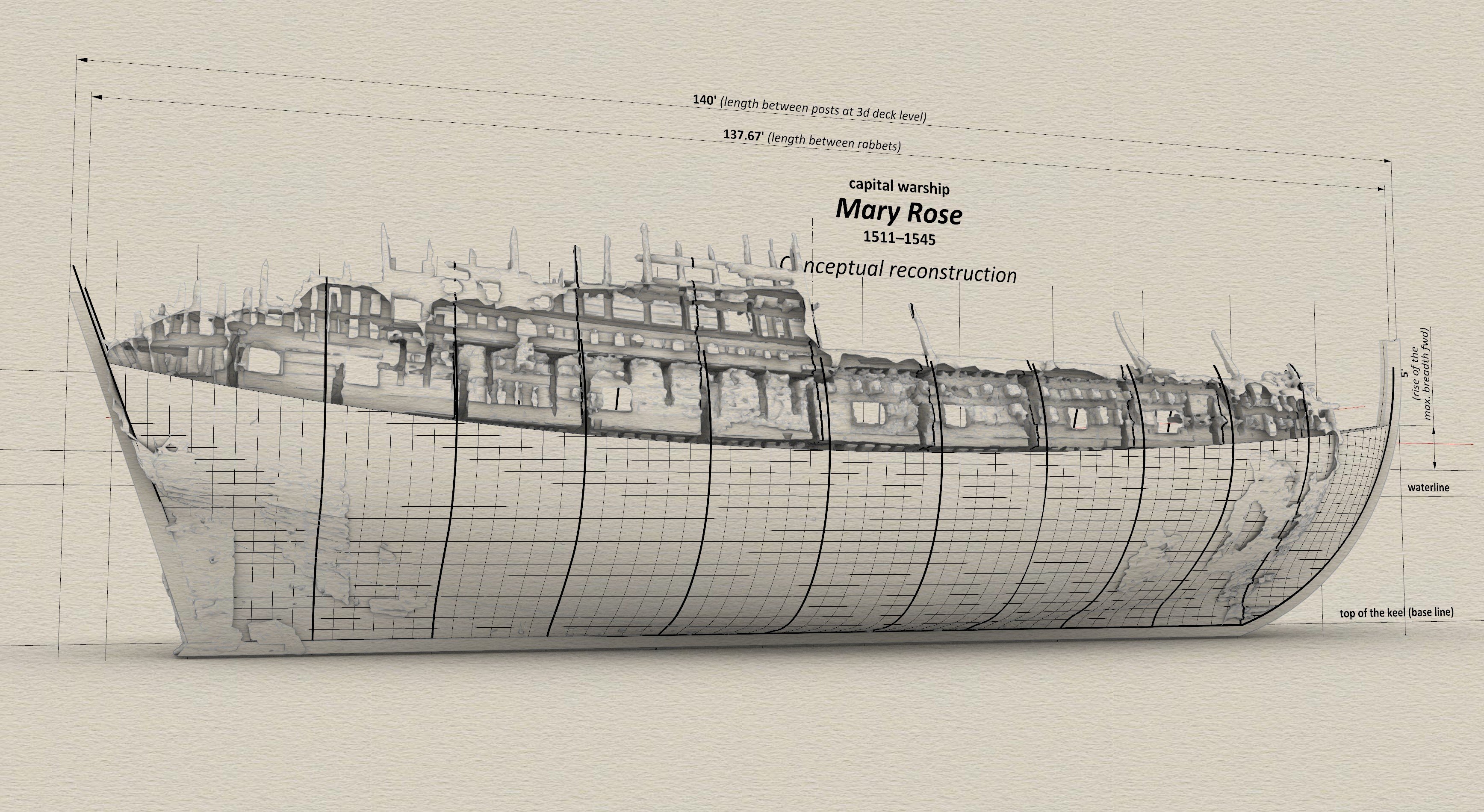
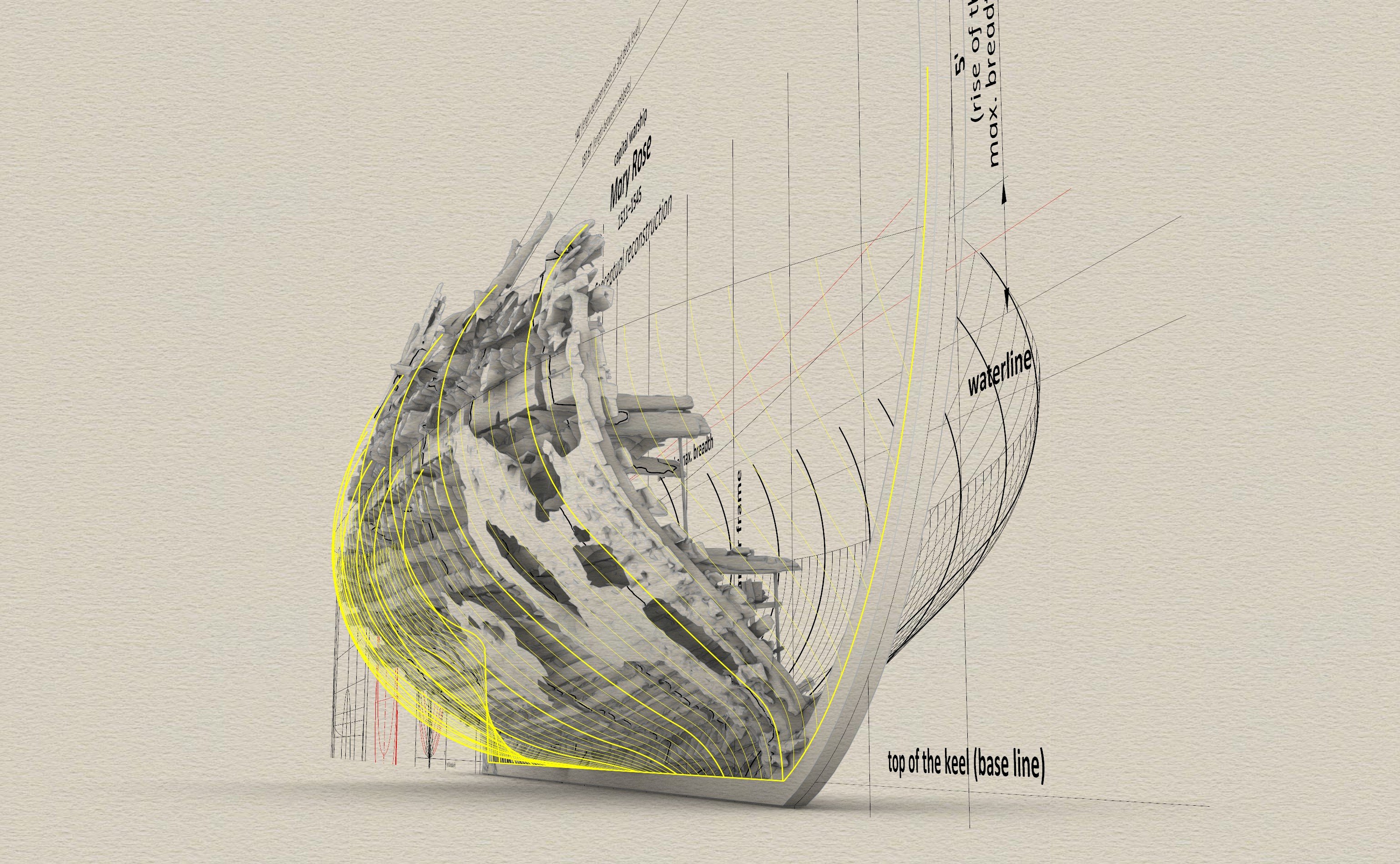
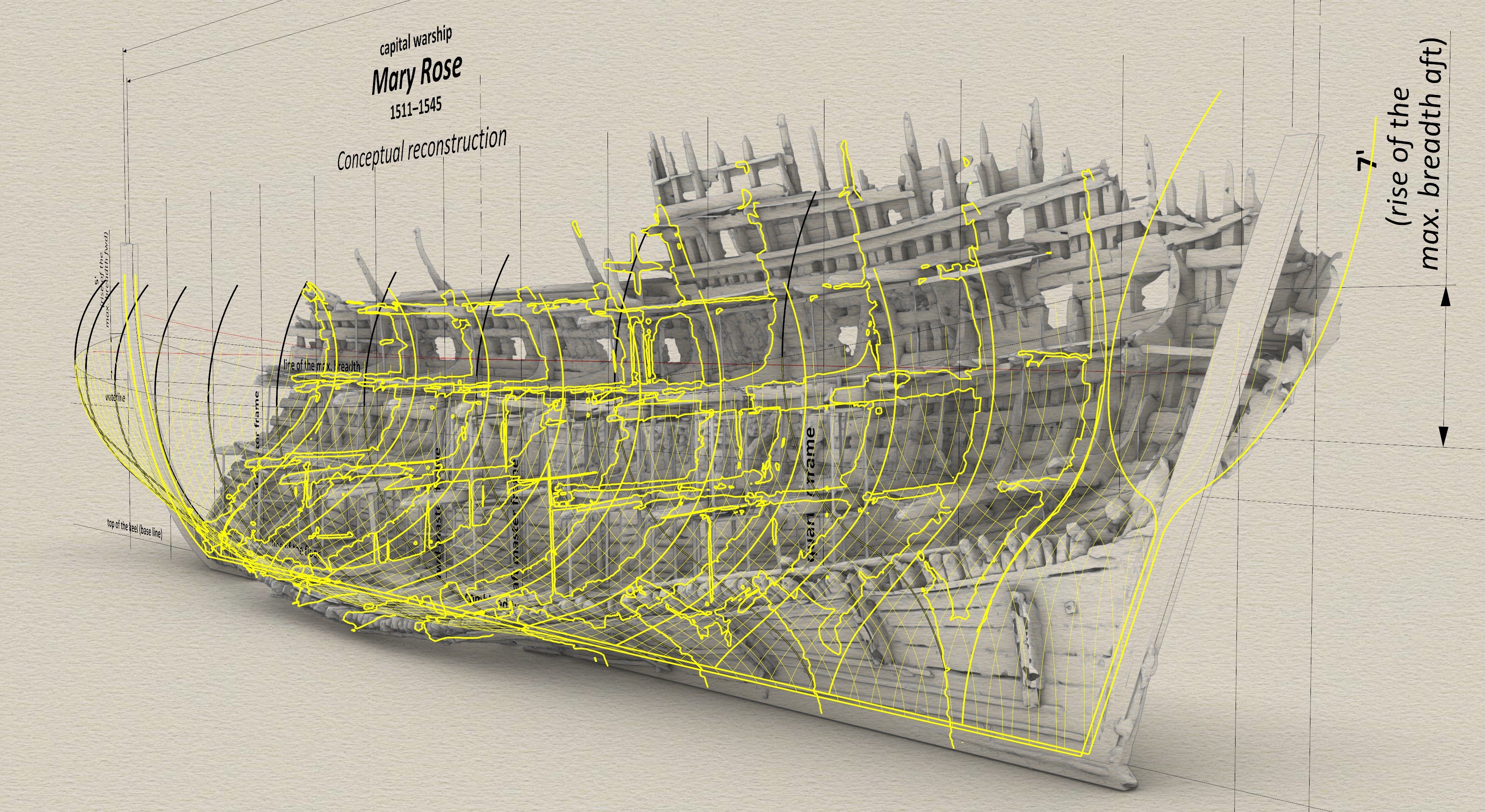
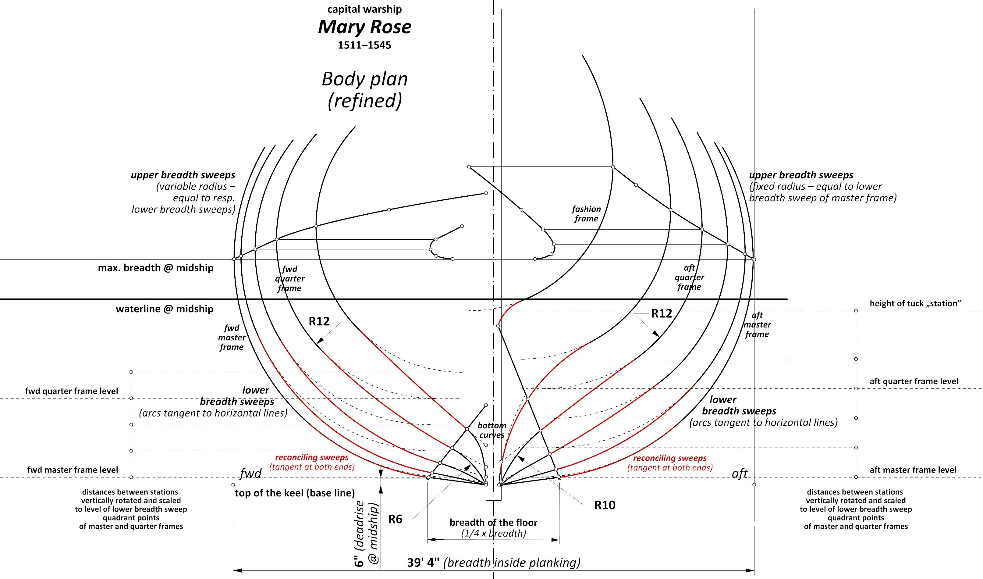
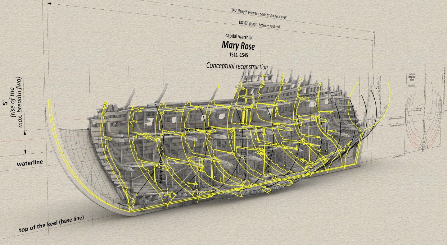
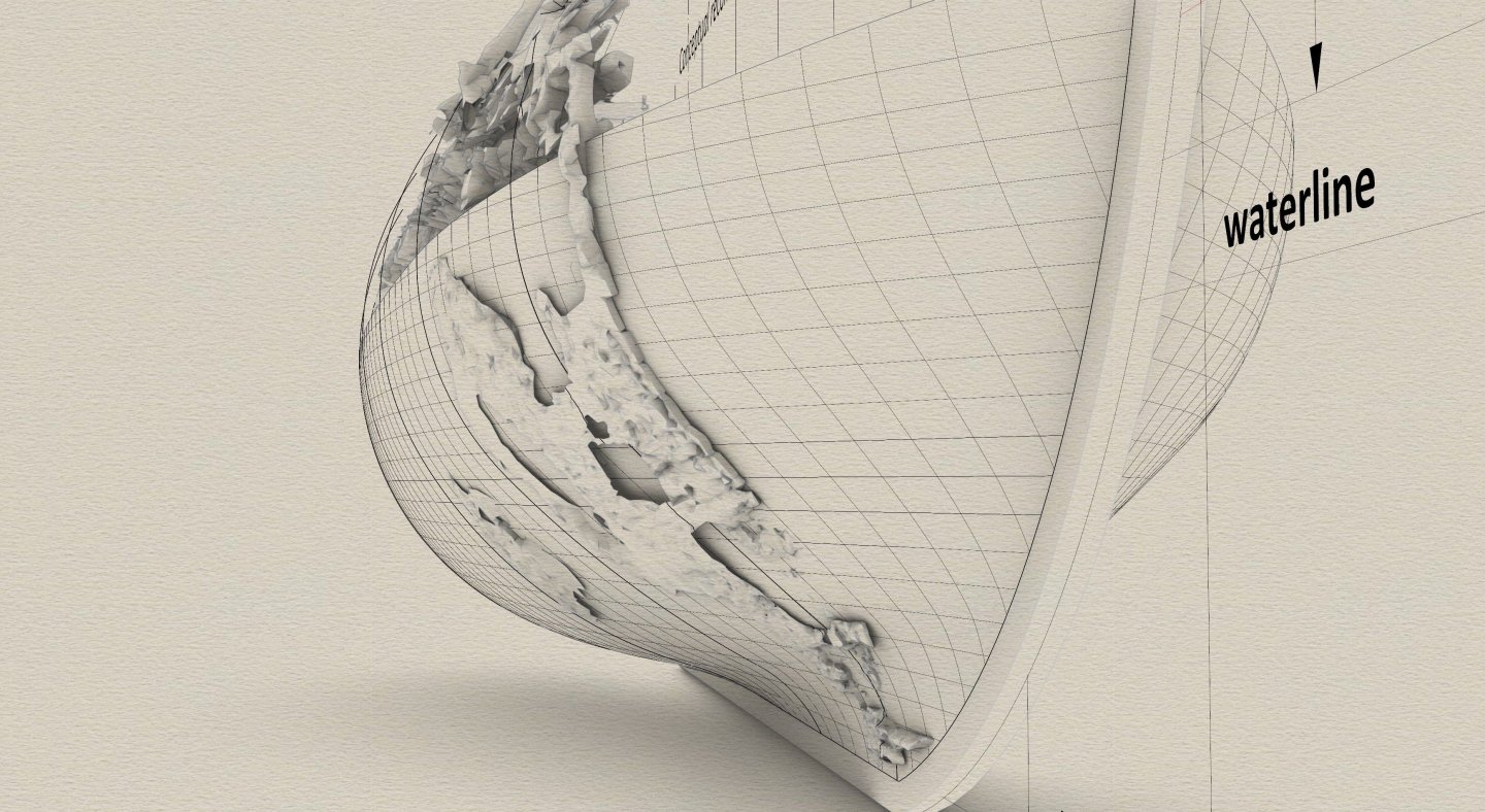
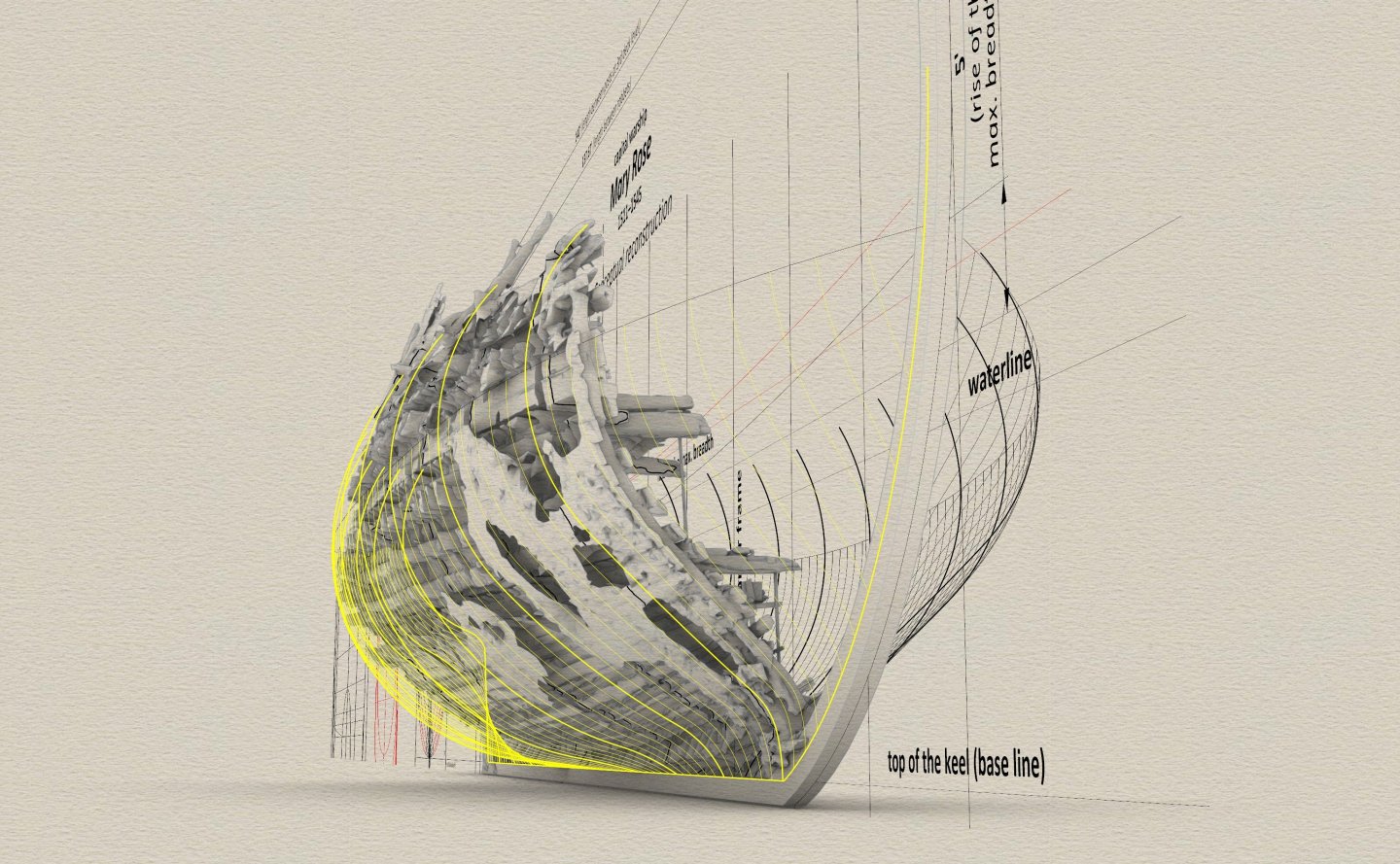
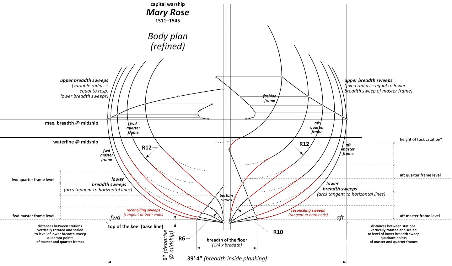
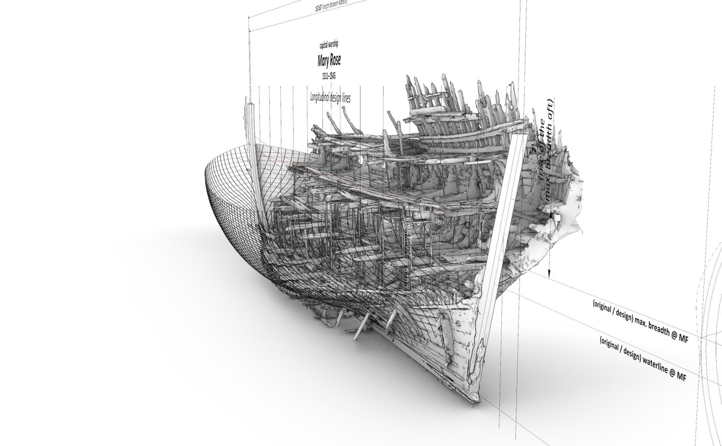
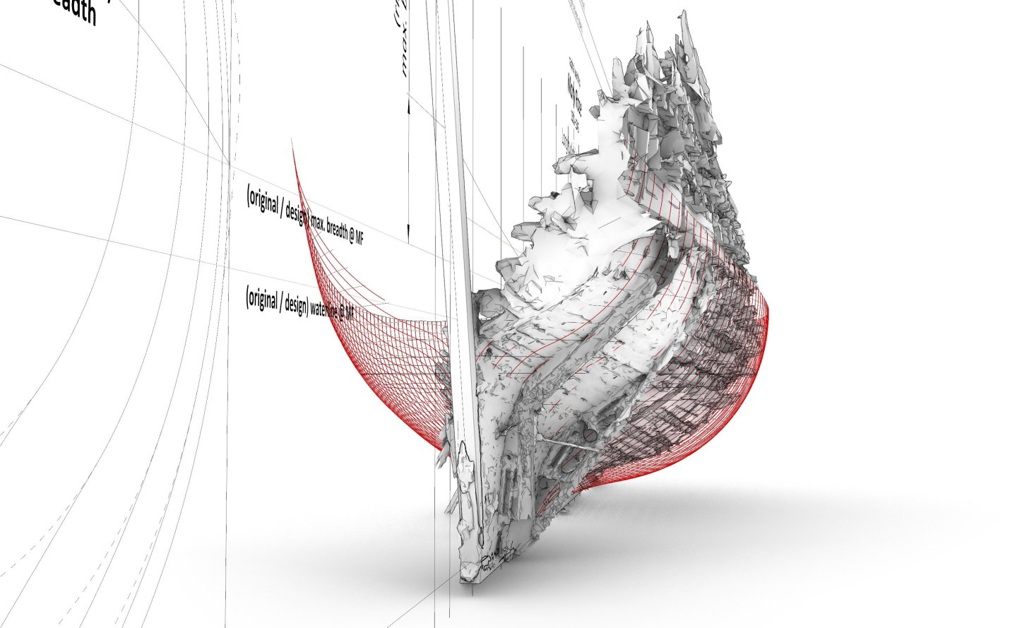
Refinement Already during the work in progress, a 3D scan of the Mary Rose wreck was accessed (many thanks to the Mary Rose Trust, and especially to Alexzandra Hildred), and although just of the ship's interior, with only a residual surfaces of the exterior planking, the scan nevertheless allowed an additional verification to be effected and even some refinement of the results already obtained as well. First of all, the scan itself had to be corrected, which proved to be quite difficult in itself due to the particularly severe and at the same time extremely complicated nature of the distortions of the original (wreckage). Overall, this verification went happily well, except that it sparked an additional local correction of the bow shape, consisting of a slight increase in hull volume at this area. Most importantly, however, the previously found design concept of the ship could have remained unchanged, and even the correction of the bow shape itself could have been done precisely in a way that made use of this previously found design method, specifically by reducing the initial radius of the arc of the bottom in the forward quarter frame from 10 to 6 feet. All the rest of the geometric components followed ‘automatically’ the existing geometric procedures of the design, generating, in effect, a more full bow shape. It could be said here that this is one of the main advantages of this particular approach or way of interpreting finds of this kind. The graphics below show, among other things, pairs of corresponding contours for each station being compared, the outer lines representing reconstructed lines and the inner lines being cross-sections of the interior of the hull (thick yellow lines). The distance between these contours is, of course, due to the thickness of the frame timbers and also, in a rather irregular manner, to the thickness of the ceiling planking, riders, braces and knees. * * * The final (or refined), reconstructed body plan of the Mary Rose 1511 is as follows, and the alterations, compared to the previous variant, affects only the fore part of the hull. All of the earlier explanations on the design concept, or geometric construction, apart from the change in the value of one radius mentioned above, remain valid: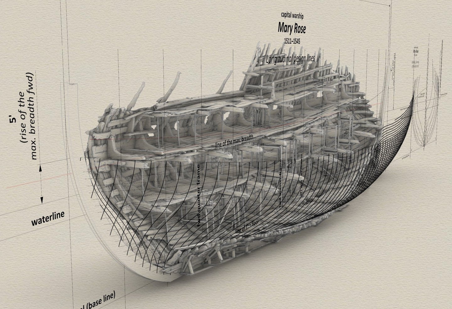


-
Mary Rose 1511 — the epitome of the Northern tradition
Waldemar replied to Waldemar's topic in Nautical/Naval History
Thank you, Martes, for this information. Somewhat spontaneously — there is a bit of irony in the fact that, for interpreting this particular case, it is the French sources that have proved so pertinent (mentioned above carrack Columbe c. 1500, Fournier's remarks of 1643, the design of l'Aurore 1697 and other French ships of the era, Duhamel du Monceau's treatise of 1752) . It should be noted that these are strictly technical issues. Up to now, as far as I am aware, attempts have been made to create such a conceptual reconstruction of the Mary Rose, however, they were based rather on English shipbuilding textbooks 100 years and more later, which describe issues that were already specific to a period when Mediterranean methods had already been adopted in England for good and developed further. Consequently, these attempts could not and indeed did not produce any meaningful results. -
Mary Rose 1511 — the epitome of the Northern tradition
Waldemar replied to Waldemar's topic in Nautical/Naval History
Thanks. I have tried to formulate the explanations as clearly as possible, even avoiding unnecessary additions that only obscure the whole picture. If there is something specific that needs more attention, just please point it out. -
Mary Rose 1511 — the epitome of the Northern tradition
Waldemar replied to Waldemar's topic in Nautical/Naval History
In general, I think it can be said that during the actual assembly of the frame structure on the building ways, the procedure was just as you explained. However, there is not at all any contradiction in this with the necessity of some frame pre-designing, because in order to use aligning battens or ribbands at all, first the shape of at least a few frames, erected in the first place even before the ribbands could be fitted, had to be defined. Only then could all the rest of the frames be erected (or even shaped according to these temporary ribbands). Similarly, in cases, when the shape of all the frames is predefined, not merely the conceptual ones, these alignment ribbands are still needed to guide the next, gradually inserted elements into the skeleton structure. Especially since at that early period the frames were not yet a unified whole, but their individual elements (floors, naval timbers, 1st futtock, 2nd futtocks, ..., toptimbers) were not connected to each other at all (so-called ‘floating’ frame components, precisely as in Mary Rose's case). This circumstance, in turn, meant that matching such separate components to the guiding ribbands, even if they had been not overly precisely cut beforehand, was almost always (better or worse) possible. However, the more precisely the whole process was carried out beforehand (i.e. designing, tracing, cutting out timbers), the less work there was with the subsequent dubbing of the resulting hull surface. In this context, it is telling and interesting to note that in Russian shipyards in the 18th century (i.e. at a time when full design on paper was employed), whole teams of carpenters were permanently employed to do nothing but dubbing, although such a peculiar “extravagance” could probably only be possible in state-sponsored ventures. But this is a familiar problem in England itself as well — William Sutherland, in his 1711 work, even strongly advocated a return to simpler design practices, essentially inherited from the Middle Ages, allowing or facilitating greater precision in all preceding stages, precisely to avoid or at least reduce this essentially rather ‘idle’ in the production sense and also economically damaging process of dubbing. To put it yet another way, these first ‘futtocks’, to which guiding ribbands or battens could be later attached, also had to be designed in a meaningful/regular geometrical way, because some random shape of these initial ‘futtocks’ would not have ensured a run of the required shape and at the same time fairness of these guiding ribbands or battens. This is precisely what this reconstruction shows — the design process of these first ‘futtocks’, only here they are called ‘conceptual frames’. Building models using the plank-on bulkhead technique is also a very good analogy. On sloppily designed bulkheads, i.e. sporting rather random shapes, it is virtually impossible to lay the planking in a smooth way. It is also worth adding that the pre-definition of the frames did not necessarily start as late as the implementation of carvel construction. For example, I am now looking at the lines of the so-called Newport ship of the 15th century, sporting clinker planking, and it tentatively looks to have been designed using exactly the same method as was employed for Mary Rose 1511. But indeed here too it is worth doing a proper survey for verification. Yes indeed, it is not a single-arc curve, but in this case it is a curve composed of two arcs of a circle (in the top projection), as is its part for the aft half of the hull. It is interesting, and probably usually surprising to today's readers, that in fact this line did not even have to be drawn beforehand on the longitudinal projections, but its coordinates could immediately be approximated on the body plan in actual size on the mould loft, especially with the help of various geometrical devices of the mezzaluna type. This was possible and at the same time particularly easy for the central segments of this line (indicated in the reconstruction diagrams above), which are already just single arcs of circles, because these central segments, i.e. between quarter frames, are tangent to the longitudinal line parallel to the ship's axis. This is a broader and interesting issue in itself, but I think I have just produced an excessively long elaboration anyway... -
Mary Rose 1511 — the epitome of the Northern tradition
Waldemar replied to Waldemar's topic in Nautical/Naval History
Oh, I should also add that the renders in the first post show the reconstructed geometric model in an earlier version, that is, with a slightly larger forward rake than in the later, final version. This of course has to do with the incomplete wreckage (no bow) and having to choose between several possibilities. I could, admittedly, replace these renders or add new ones quite easily, but essentially the intention is that the design method recreated for this case, and presented in such great detail, would enable interested individuals to create a plan or model of this ship themselves. -
Mary Rose 1511 — the epitome of the Northern tradition
Waldemar replied to Waldemar's topic in Nautical/Naval History
Thank you Trevor. The shortest answer is that both. But indeed, this is a more interesting issue (at least to me), deserving of a slightly more extensive response. To start, yes indeed it is a kind of reverse engineering, hellishly difficult, time-consuming and fraught with the risk of an easy mistake, especially since in this particular case the input material (a shipwreck), is far from ideal in the sense of its present geometrical regularity of shape, and secondly this exercise had to be based on material already interpreted (indirect illustrations instead of, for example, a 3D scan of the original object), which creates additional complications and risks. The aim is to create a complete, coherent and unambiguous conceptual (geometric) (re)construction, which makes it possible to obtain just such a shape as a whole. For this era, they still have to meet the condition of obtaining immediate ideal shapes, in the sense of their fairness, as in those days design on paper, at least complete design, was not yet practised, which only allows for smoothing treatments already in the design stage (i.e. synchronizing cross-sections, waterlines, buttocks, possibly diagonals). In general, it can be said that the geometric methods applied cannot be completely arbitrary, but must follow firmly from procedures and methods known from written and graphic sources derived from period shipbuilding treatises, manuals, drafts etc. However, this is not a limitation, quite the contrary — familiarity with methods known from these sources makes it easier, if not at all possible, to make such reconstructions successfully. I would also add that I would probably never have obtained (I trust) the correct result in this particular case if it were not for the knowledge and previous experience gained in several dozens of similar projects, and always based on period material (whether plans, wrecks or period models). Ultimately, it turns out that through this graphical method of analysis, it is possible to find out (or prove) things that are absent or too vaguely described in the relevant written works for just a particular region and time. In other words, its results perfectly complement and even correct the current knowledge derived from unfortunately incomplete written sources of the period (and mistakenly or too arbitrarily interpreted today). Perhaps it is a kind of deficiency in my descriptions that there is not a detailed reference to the sources for every detail every time, but such a way would hamper my essential task and, moreover, in the vast majority of cases, I guess it would easily exhaust the readers. In this sense, I do indeed have inclinations to show finished results rather than ways of achieving them. I hope I have formulated all the above and touched the issue in a way that answers your concern or question . -
Mary Rose 1511 — the epitome of the Northern tradition
Waldemar replied to Waldemar's topic in Nautical/Naval History
Thank you for your attention so far, Waldemar Gurgul -
Mary Rose 1511 — the epitome of the Northern tradition
Waldemar replied to Waldemar's topic in Nautical/Naval History
If one assumes, in line with the results of the investigation so far and with the present, general state of knowledge, that the Mediterranean methods together with its multi-arc frame construction (usually three) were only widely implemented in England at the times of Mathew Baker, i.e. in the second half of the 16th century, and that until then only the frame construction appropriate to the Northern European tradition, that is sporting just one arc (not counting reconciling or bilge sweep), but of variable radius, was employed, as shown in this presentation using the Mary Rose as an example, then this circumstance can be used to interpret perhaps more rationally and confidently other archaeological finds from this early period in a poorer state of preservation than the Mary Rose. For instance, in the first volume of the Mary Rose monograph (Peter Marsden, Sealed by Time. The Loss and Recovery of the Mary Rose, 2003), on page 141, there is an interesting juxtaposition of cross-sections of two important wrecks dating from the “pre-Mediterranean” period in England on an equal scale — the Mary Rose 1511 and the so-called Woolwich ship (possibly Sovereign 1487). The assumption of design homogeneity in this early period, specifically the single-arc frame design, allows the breadth and its height of the Sovereign to be determined quite accurately solely on the basis of the modest surviving fragment of the bottom section of the hull (subject, of course, to its minimal geometric distortion), as demonstrated illustratively in the diagram below.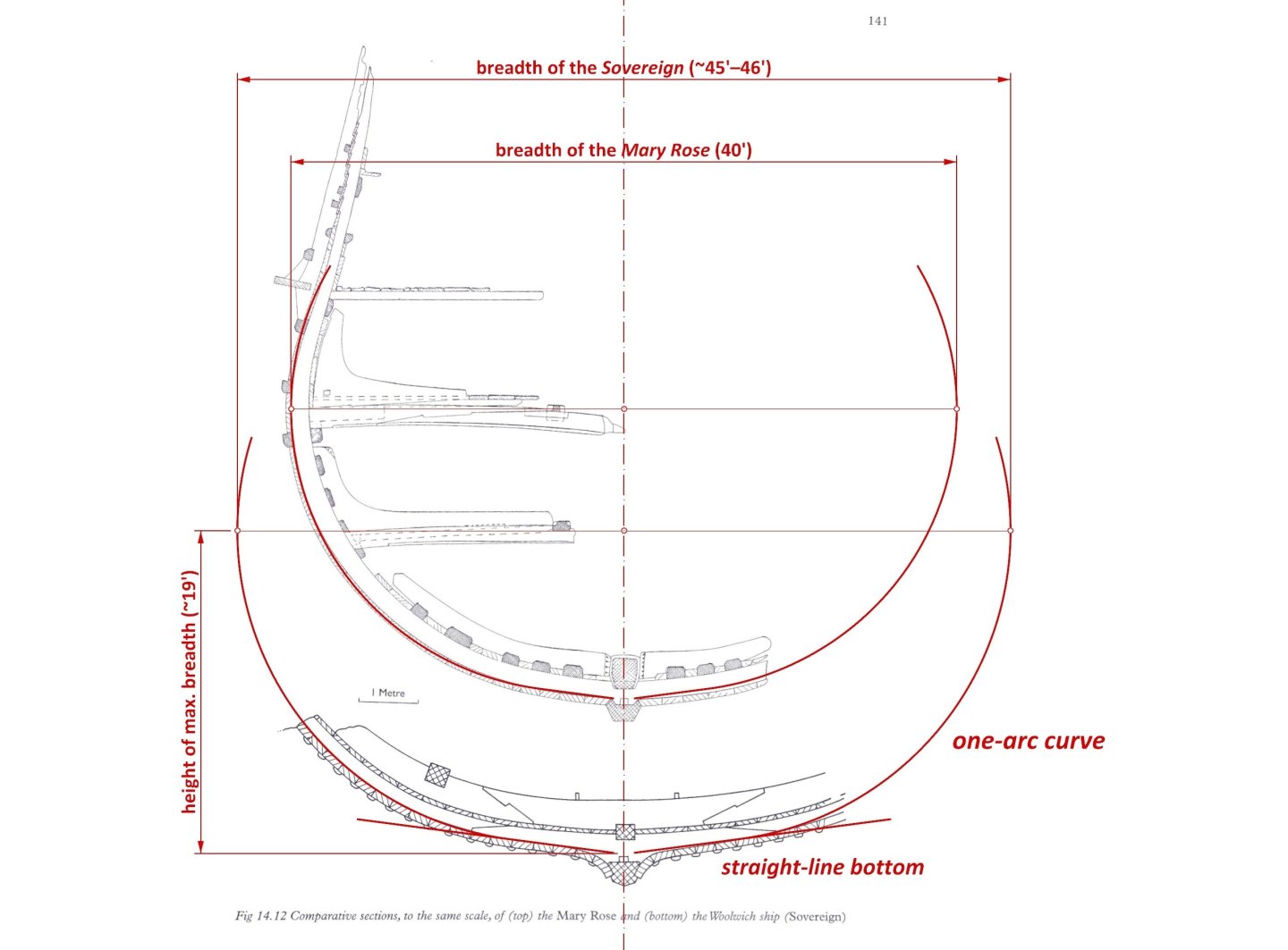
-
Mary Rose 1511 — the epitome of the Northern tradition
Waldemar replied to Waldemar's topic in Nautical/Naval History
Patrick ( @Baker ) came up with the idea to post copies of the publications mentioned above in this thread as well (thanks, Patrick), so they are always ready to be consulted. I think it's a good idea and that they are both in the public domain. Voilà. Cate Wagstaffe, Furring in the Light of 16th Century Ship Design, 2010: Wagstaffe Cate - Furring in the Light of 16th Century Ship Design - 2010.pdf Jens Auer, Thijs J. Maarleveld, The Gresham Ship Project. A 16th-Century Merchantman Wrecked in the Princes Channel, Thames Estuary, 2014: Auer Jens - Maarleveld Thijs J. - The Gresham Ship Project. A 16th-Century Merchantman Wrecked in the Princes Channel, Thames Estuary - 2014.pdf -
Mary Rose 1511 — the epitome of the Northern tradition
Waldemar replied to Waldemar's topic in Nautical/Naval History
It can probably be explained in some simplistic terms that initially, with the usual use of ships to carry cargo low in the holds, there was no major problem with this phenomenon, and even a certain “softness”, provided by the round sections, may have been desirable so that more violent gusts of winds would not break the masts. It was only when dedicated warships with heavy artillery began to emerge, and at an height unfavourable from the point of view of stability, that the problem hit particularly hard. The general conclusion is, although hardly surprising, that in reality there is no such thing as a universal solution for all applications, or at least it is rarely possible. -
Mary Rose 1511 — the epitome of the Northern tradition
Waldemar replied to Waldemar's topic in Nautical/Naval History
Yes, that's probably the best summary. A few dozen extra tons of difference in the original and new artillery configurations, a few dozen extra tons of battle crew with their heavy equipment. And if the repair of the ship in 1536 was mainly to reinforce her existing structure, as incidentally was done quite routinely in later times, then an additional few tens of tons of all the new reinforcing elements can be added, especially the standard knees and diagonal braces. The results of the dendrochronological studies are admittedly quite piecemeal, but at least they now suggest or at least do not contradict just such a repair scenario. All in all, at least 100 additional tons, perhaps as much as 150, and most of it at a height quite unfavourable to the ballast stability of the ship. And if still the “whole” crew was on the wrong side at the wrong time, then... Below is a graphic showing clearly which items have been examined for their age and what the results of this research are (from David Childs, The Warship Mary Rose. The Life & Times of King Henry VIII's Flagship, 2007):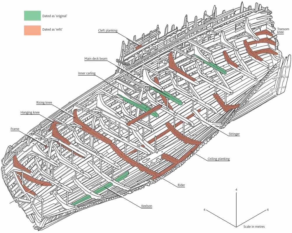
-
Mary Rose 1511 — the epitome of the Northern tradition
Waldemar replied to Waldemar's topic in Nautical/Naval History
Thank you for showing this . And a huge round of applause to today's marine engineers for this essentially makeshift repair! It's not the only case they have struggled with the specifics of old designs, and this despite the same applicable laws of physics now and then and all the scientific apparatus available today. Shame... I was also reminded of a case in which a professor made serious calculations from which it was irrefutably clear that the length of a ship had to be at least about three and a half times its breadth to be capable of controlled navigation. Just how to reconcile the results of these calculations with the vessel San Juan of about 1550, with a ratio of 2.8 : 1 on the draught line, which not only crossed the entire Atlantic, but still hit the exact spot it was intended to reach with a whole fleet of similar whalers. -
Mary Rose 1511 — the epitome of the Northern tradition
Waldemar replied to Waldemar's topic in Nautical/Naval History
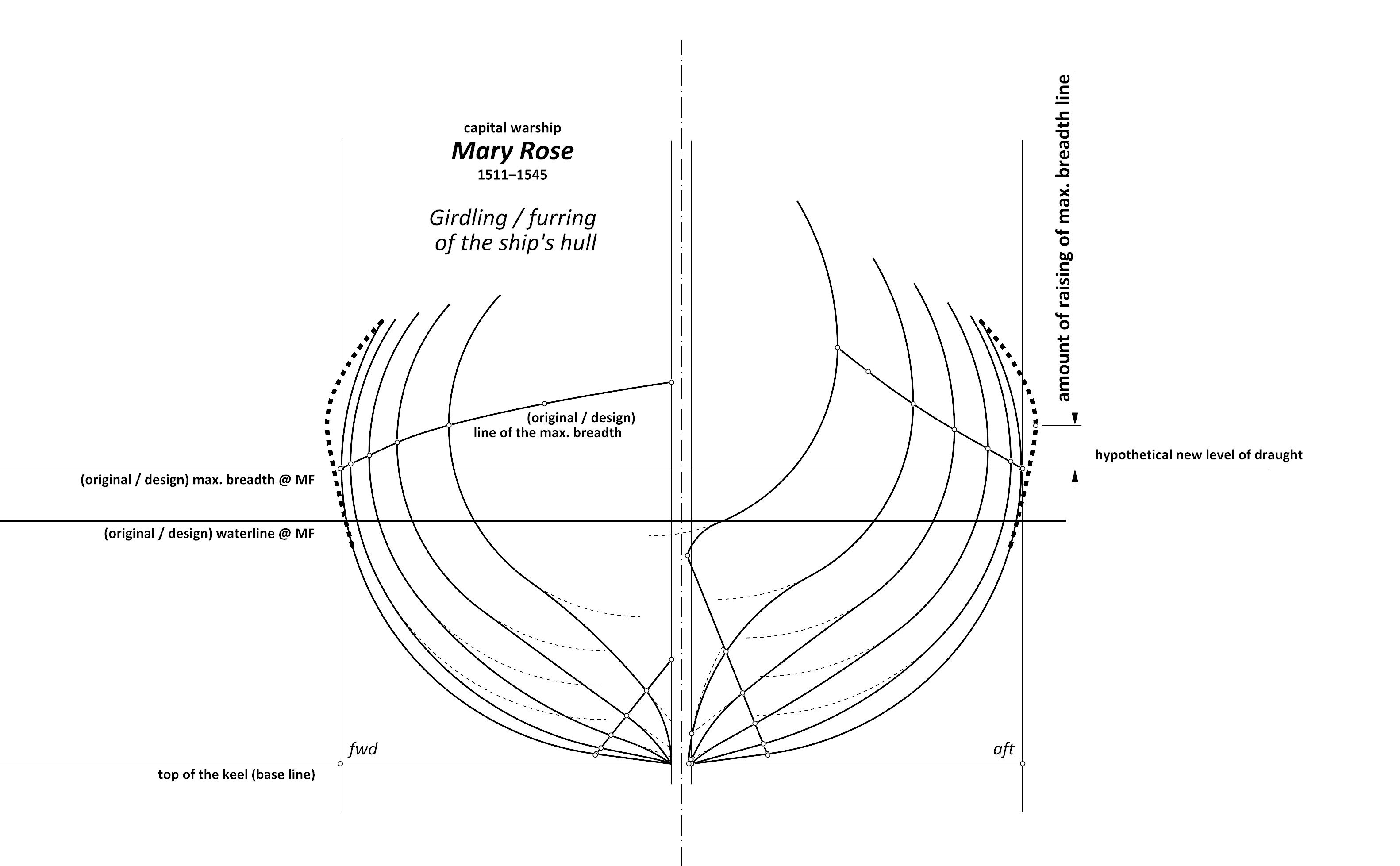
To show graphically what Martes had in mind, here is another diagram showing the possibility of girdling/furring, hopefully in a more realistic way, nevertheless, like the previous one laden with dimensional uncertainty so it should rather be taken as an illustration. As a reminder, as the draught of a ship increases (e.g. proves to be too great after launching and fitting out, which is particularly the case for warships), broadening the hull by girdling/furring should also raise the greatest breadth of the hull accordingly, so as to maintain the desired distance, usually 2–3 feet.
-
Mary Rose 1511 — the epitome of the Northern tradition
Waldemar replied to Waldemar's topic in Nautical/Naval History
This is correct, because we do not know precisely this level after the ship's refit, and in any case it was variable depending on the actual weight of the cargo. Thus, of necessity, these particular diagrams simply show the general principle or idea of carrying out this process that could have been applied, without exact dimensional reconstruction. There is no need for this anyway, as it has not been put into practice. As for the illustration showing the Gresham ship, it may not show the geometry very accurately. It is rather a more or less loose graphic reconstruction, also out of necessity. Please see how fragmentary the preserved parts of this wreck are (illustration also from the report mentioned above). Actually, the greatest breadth of the hull need not or should not be far away from the draught level. Thus, if the ship's draught was not planned to increase, there was no need to raise it.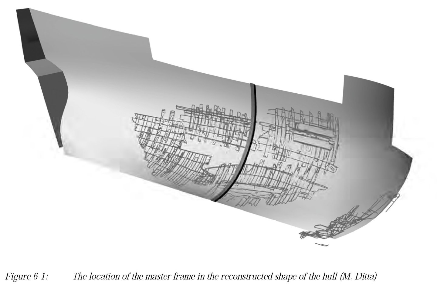
-
Mary Rose 1511 — the epitome of the Northern tradition
Waldemar replied to Waldemar's topic in Nautical/Naval History
Did the Mary Rose have to capsize? Apart from a better, or more prudent, vertical distribution of weights on the ship, a very effective and often used way to improve the lateral stability of ships sporting tumblehome was to increase their breadth. However, this does not mean increasing the breadth of the hull per se or by any means, but ideally this had to be done in such a way as to “maximise” the breadth above the draught line (typically 2–3 feet) while keeping it as intact as possible at the water level itself. This is shown in the diagram below (dashed lines). In this way, a dramatic improvement in so-called shape stability (as opposed to ballast stability) can be achieved. This procedure was called furring or girdling, depending on the structural way it was performed (for more on this see, for example, Cate Wagstaffe, Furring in the Light of 16th Century Ship Design, 2010). In an archaeological context, such a case is exemplified by the so-called Gresham ship of the 16th century (for more on this see Jens Auer, Thijs J. Maarleveld, The Gresham Ship Project. A 16th-Century Merchantman Wrecked in the Princes Channel, Thames Estuary, 2014) and a graphic from this report specifically illustrates the essence of this commonly used solution for unstable ships on a concrete extant shipwreck. It is no coincidence that the Gresham ship also features a round hull section having a very narrow bottom, precisely as the Mary Rose 1511.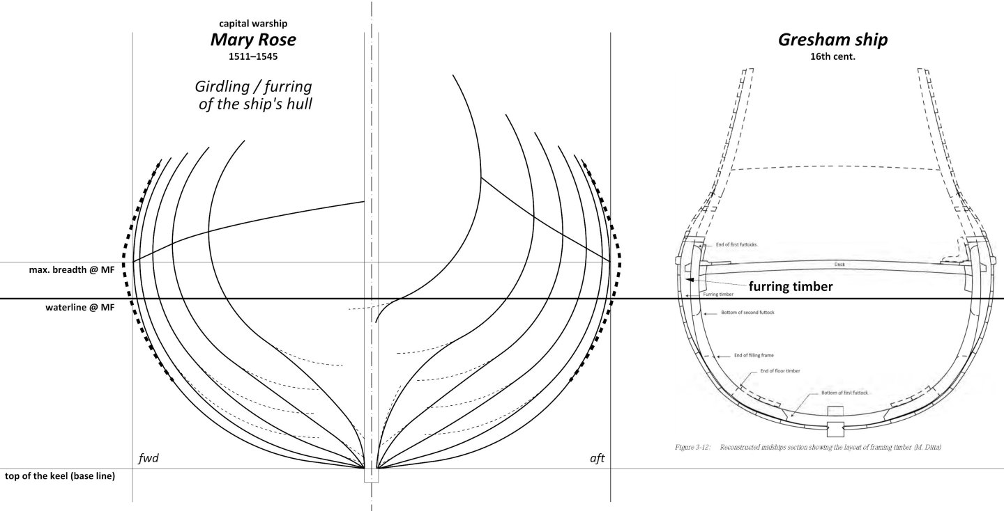
-
Mary Rose 1511 — the epitome of the Northern tradition
Waldemar replied to Waldemar's topic in Nautical/Naval History
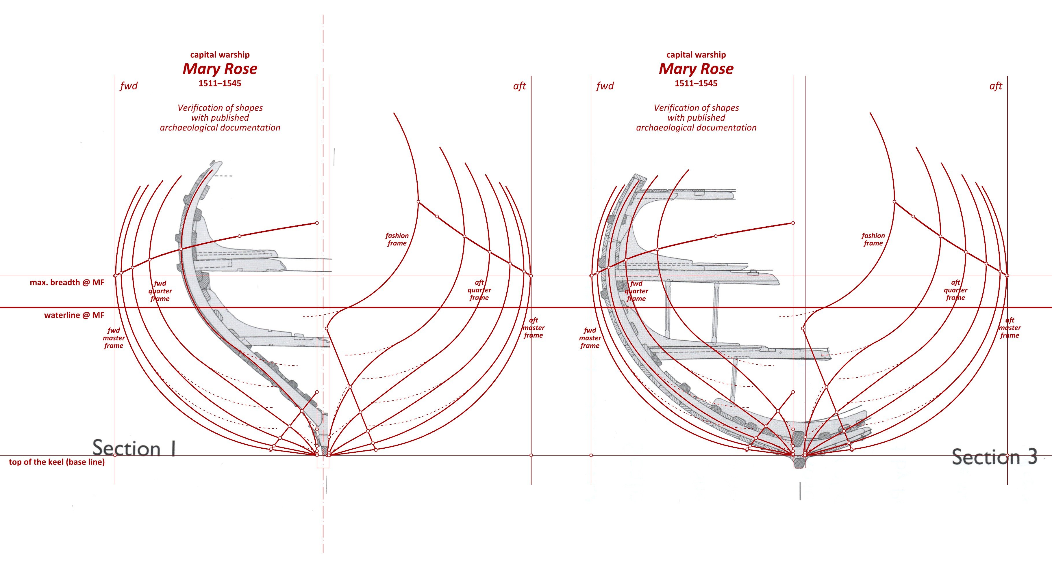
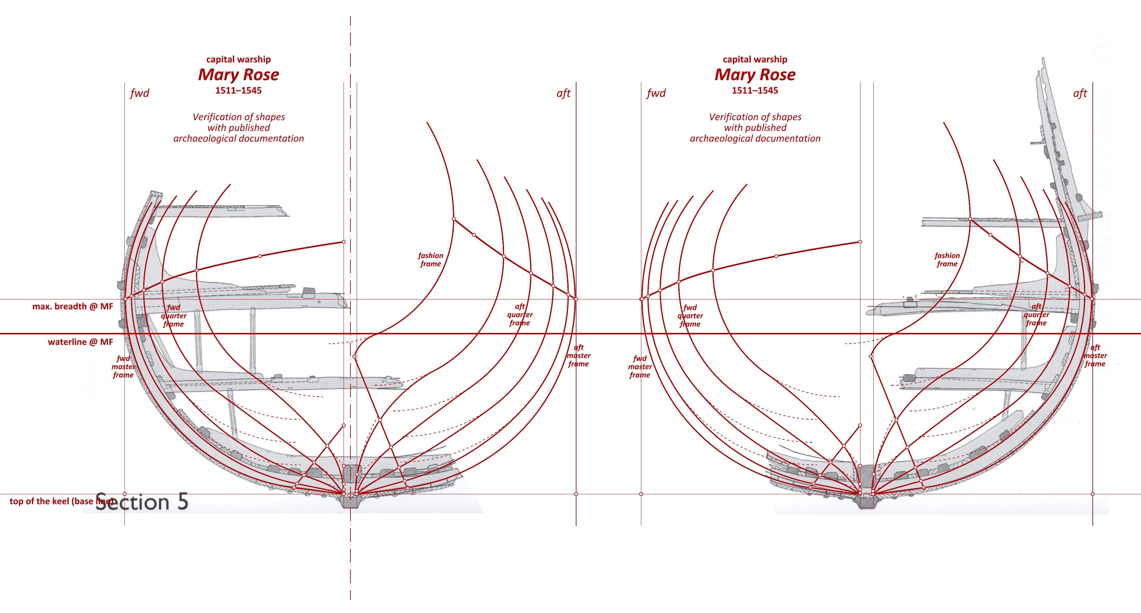
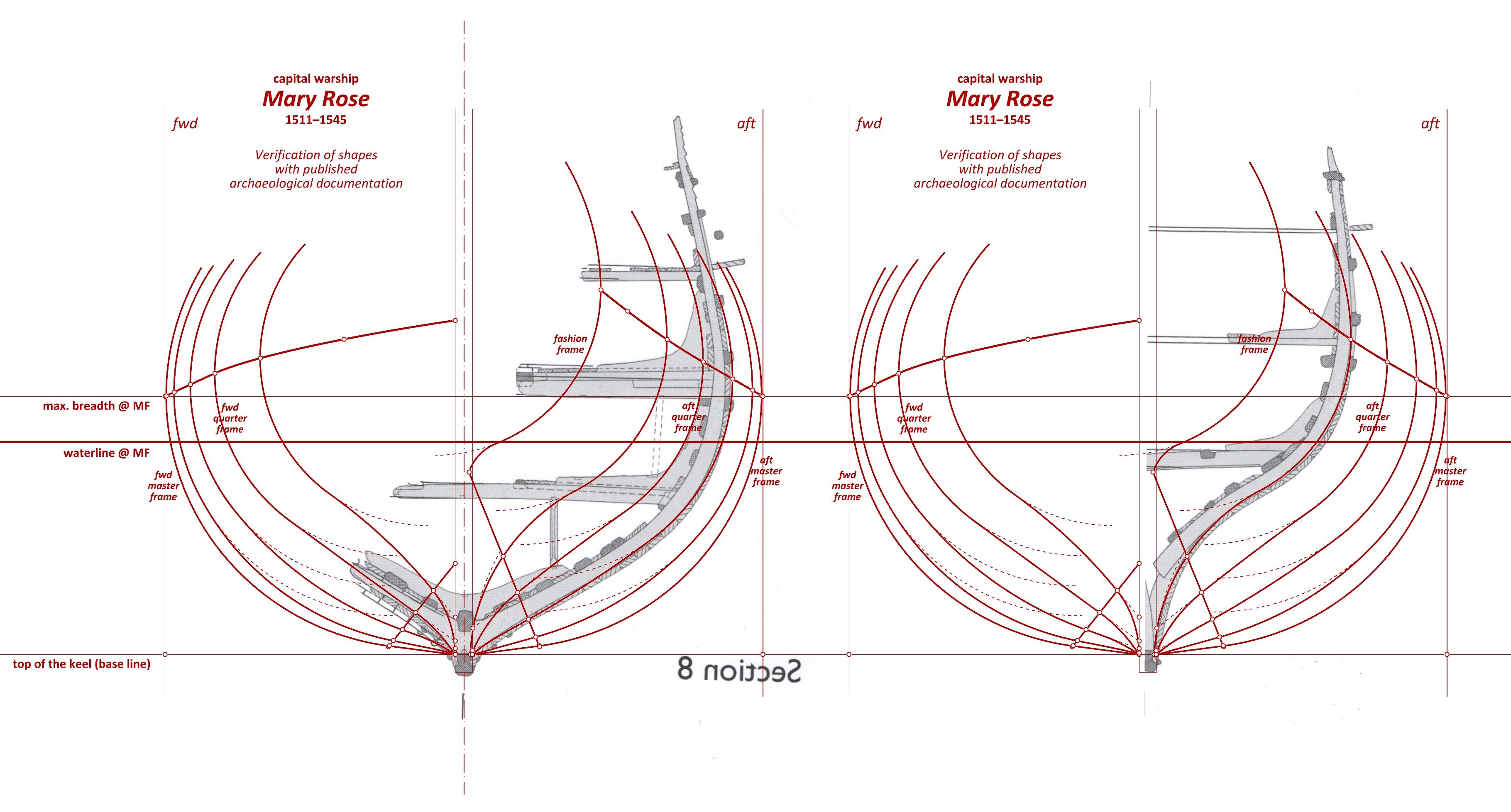
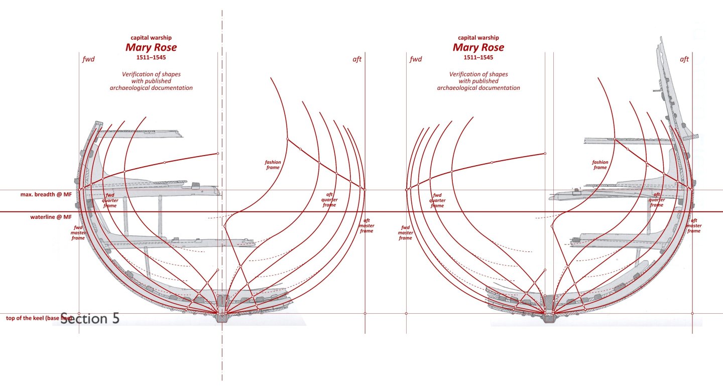
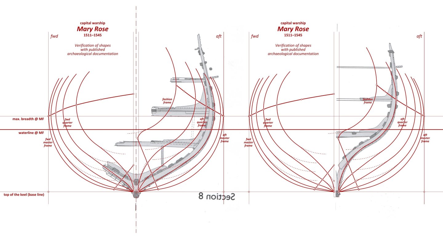
Verification of the results obtained with the (published) archaeological evidence is naturally a mandatory component of the whole exercise. Here this will be demonstrated by using the cross-sections of the hull of the wreck published in the monograph by the Mary Rose Trust as an example, but the analogous cross-sections in the ship's monograph by Douglas McElvogue are equally good. In contrast, many of the other illustrations in both monographs are inadequate for this purpose, due to their over-interpretation by the responsible authors. The placement of the frame stations in this reconstruction does not always coincide with the stations adopted in the monograph (this is particularly true of the bow section) and in such situations there cannot, of course, be full correspondence of the lines, but then one can judge by the parallelism of the contours being compared. The outer contours of the frame timbers, or in other words, the inner contours of the outer planking, should be taken as reference lines.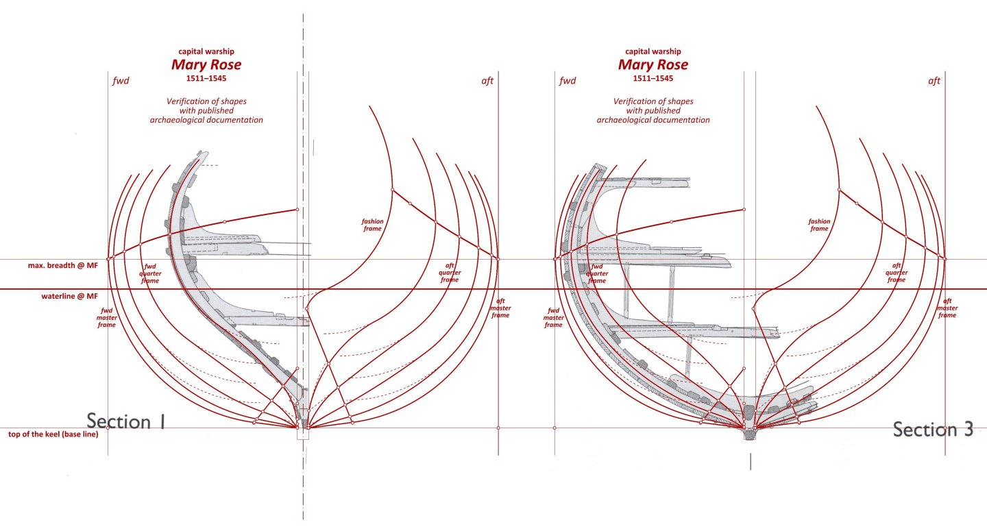
-
Mary Rose 1511 — the epitome of the Northern tradition
Waldemar replied to Waldemar's topic in Nautical/Naval History
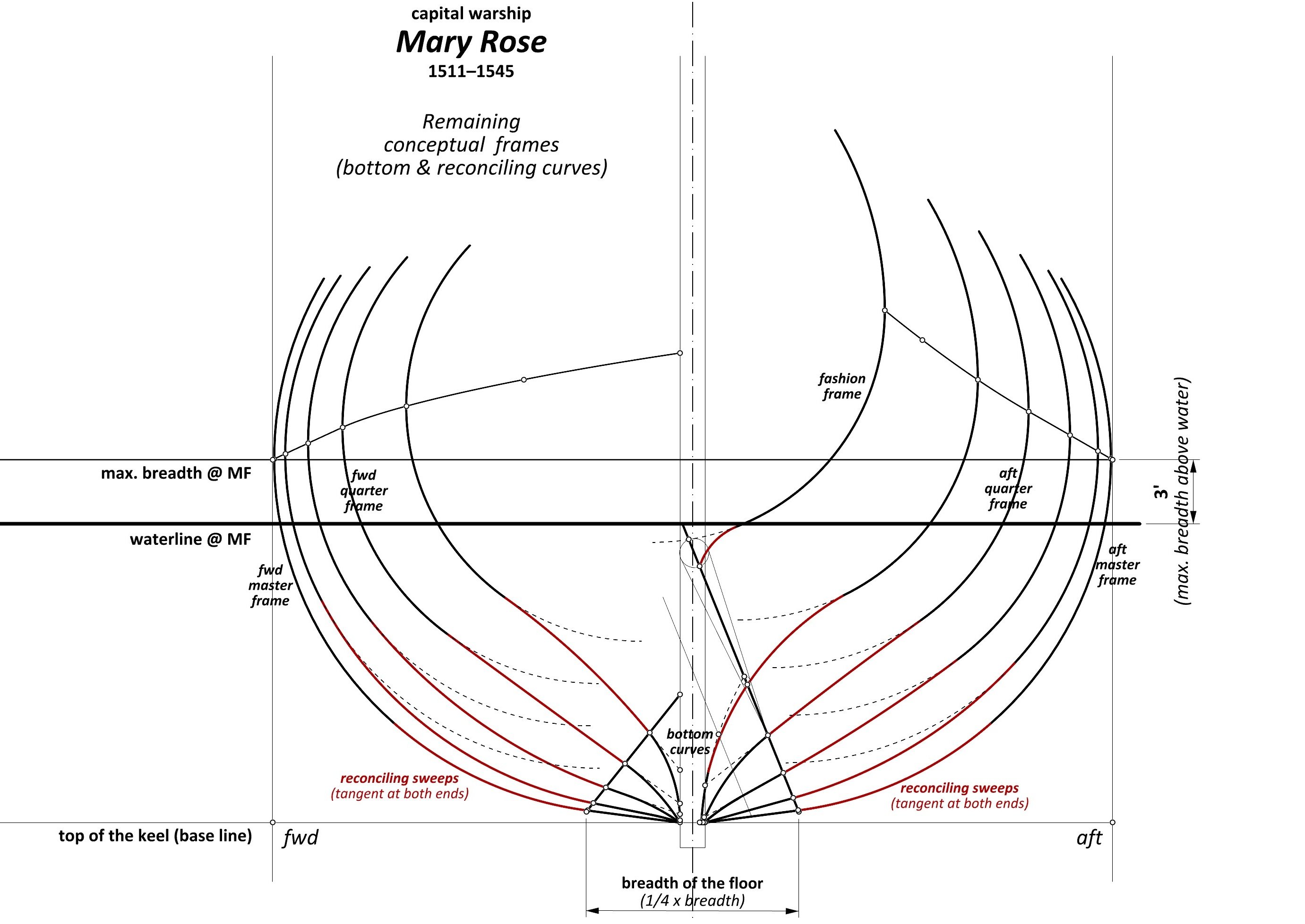
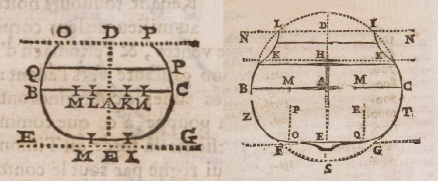
Remaining conceptual frames (bottom & reconciling curves) In the final stage of forming the conceptual frames, the botttom curves are joined to the lower breadth sweeps by reconciling sweeps (red), tangentially at both ends, with the reconciling sweeps starting from points on the line of the floor. Where needed, the straight bottom lines are completed by arcs, here all with a radius of 10 feet, the same as for the arcs of the bottom of both quarter frames. This, with the exception of the first frame, where this arc is also tangent to the vertical line of “keel”, and its resulting radius is about 6 feet 11 inches. The diagram also shows the geometric construction used to draw the last frame, which requires special treatment due to its position close to the specific sternpost/fashion frame assembly. * * * Reasons for the disaster of the Mary Rose Diverse, sometimes quite conspiracy-oriented reasons have been put forward as to what may have led to the ship's disaster in 1545. It is difficult to argue with theses for which there is no hard evidence in fact, however, it can be said with certainty that the very shape of the Mary Rose's hull is already quite unfavourable from the point of view of lateral stability. Without going into complicated explanations of a theoretical nature, this shape can be compared to a circular in cross-section beam floating in water, which, when set in motion, easily rotates around its axis. In terms of Mary Rose's specific round cross-section, as long as the ship's centre of gravity was relatively low and the line of greatest breadth was sufficiently high above the water (seemingly 3 feet by design, which is quite a standard value), there was little danger, and the ship could even have excellent seaworthiness. However, with the reconfiguration of the artillery armament to be much heavier than the original, and in addition the embarkation of a battle crew of several hundred, together with heavy combat equipment, there must inevitably have been a significant raising of the centre of gravity of the entire ship, and worse, a simultaneous lowering of the greatest breadth of the hull to water level, which already ultimately devastated the lateral stability of the ship. Actually, it probably no longer matters how the gun ports on the Mary Rose were closed, directly by the gun crews or by someone else, for example on the upper deck. Vasa 1628 had the gun ports operated directly by gun crews, and still did not avoid disaster for the same reason. Over time, the relationship between stability and the cross shape of the hull was better realised, and in 1643 George Fournier was able to state in his Hydrographie: Although the practice [of employing round hull sections], which I described in the previous chapter, has long been and is still widely followed, quite a number of brave workmen, whether French, English or Dutch, depart from it for two reasons. The first, that such ships, being almost round, heel too much in the water. Secondly, because they usually have too narrow a bottom [which is precisely the particularity of Mary Rose – WG]. Below, a round hull cross-section from Fournier's Hydrographie according to the old manner on the left and on the right the shape according to the new manner sporting a wide bottom, laterally more stable.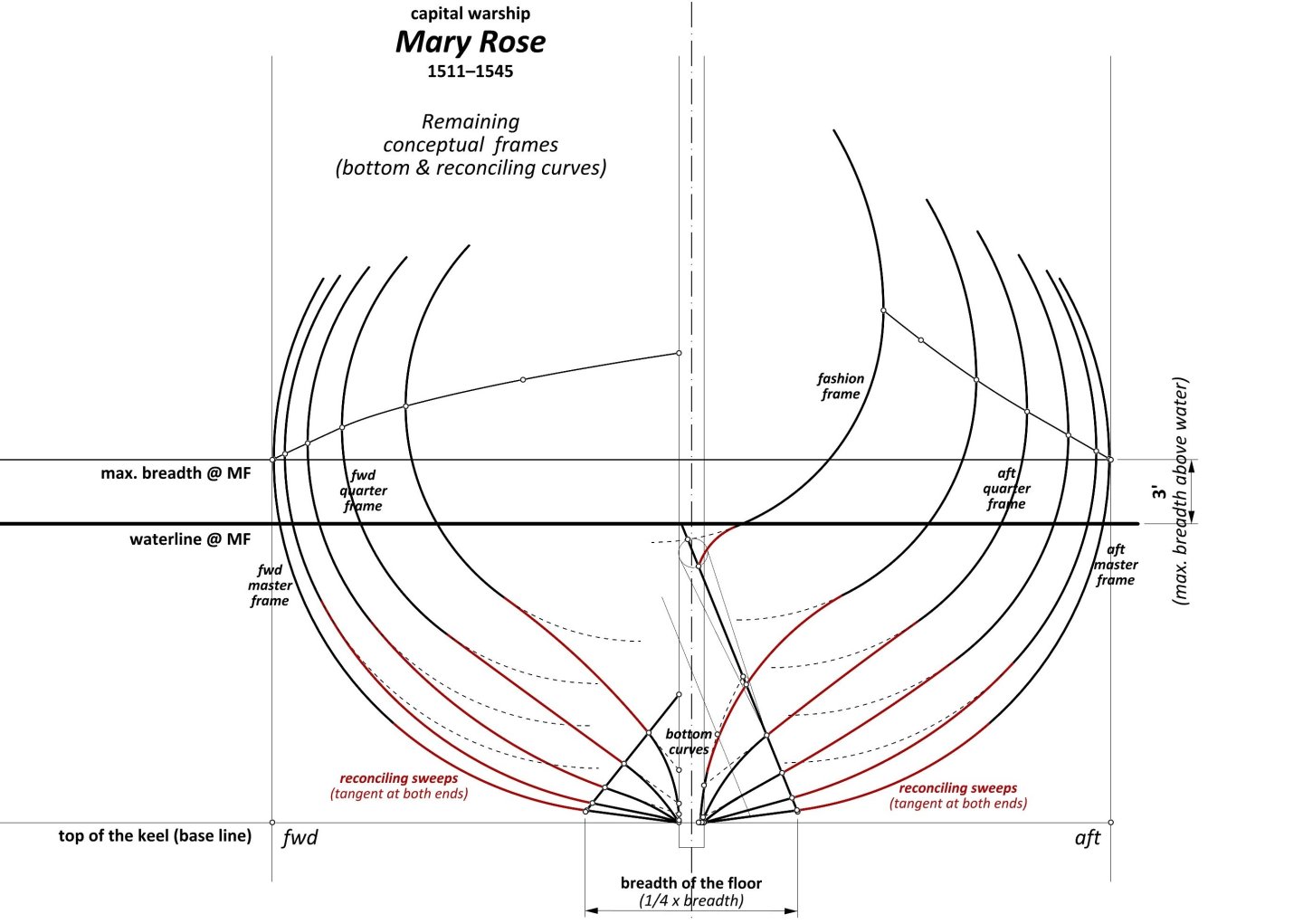
-
Mary Rose 1511 — the epitome of the Northern tradition
Waldemar replied to Waldemar's topic in Nautical/Naval History
That's right. To put it yet another way, these are ‘entire’ single circle arcs . * * * Remaining conceptual frames (curves of the bottom) Now, to make the surface of the bottom/“flat” fair, auxiliary lines need to be drawn on the body plan (dashed lines on the first diagram), extending from point A and tangent to the corresponding bottom arcs of the quarter frames. The intersections of these auxiliary lines with the vertical line of the ‘keel’ yield vertical co-ordinates (points B), which should then be transferred to the quarter frames stations on the side projection (second diagram). Longitudinal (other) auxiliary lines can now be drawn, the function of which is essentially to sharpen the hull in zones close to the keel. The intersections of these longitudinal auxiliary lines with the vertical station lines give co-ordinates, which are then returned to the body plan, so that bottom curves for all the remaining conceptual frames can be drawn (as straight lines at this point, except for the last station, which should in principle be an arc from the start – to be discussed separately).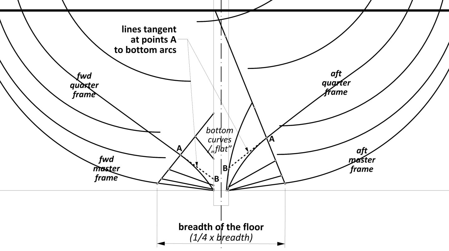

-
Mary Rose 1511 — the epitome of the Northern tradition
Waldemar replied to Waldemar's topic in Nautical/Naval History
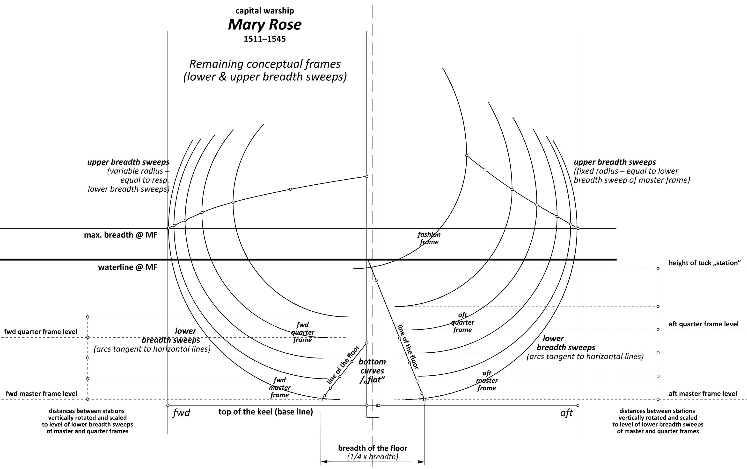
Remaining conceptual frames (breadth sweeps) The procedure for tracing the lower breadth sweeps is fairly straightforward, and involves first creating a vertical ‘scale’ (separately for the two halves of the hull), which horizontal tiers (lines) match the corresponding frame stations. If the distances between the frame stations are equal, the result will be that the distances between the horizontal tiers of this ‘scale’ will also be equal, and vice versa, as in case of the last, additional height of tuck “station”. The initial reference segment for creating this ‘scale’ is the vertical distance between the respective levels of the lower breadth sweep quadrant points of the previously defined master and quarter frames. All that is left is to draw the arcs themselves for all the remaining conceptual frames, in such a way that they are tangent to the horizontal lines thus determined (see diagram). The upper breadth sweeps for the aft half of the hull sport fixed radius, equal to the radius of the lower breadth sweep of the master frame, while for the forward half of the hull these radii are variable, equal to the corresponding lower breadth sweeps.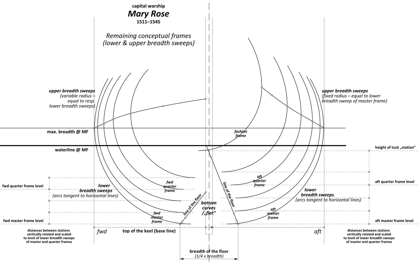
-
Mary Rose 1511 — the epitome of the Northern tradition
Waldemar replied to Waldemar's topic in Nautical/Naval History
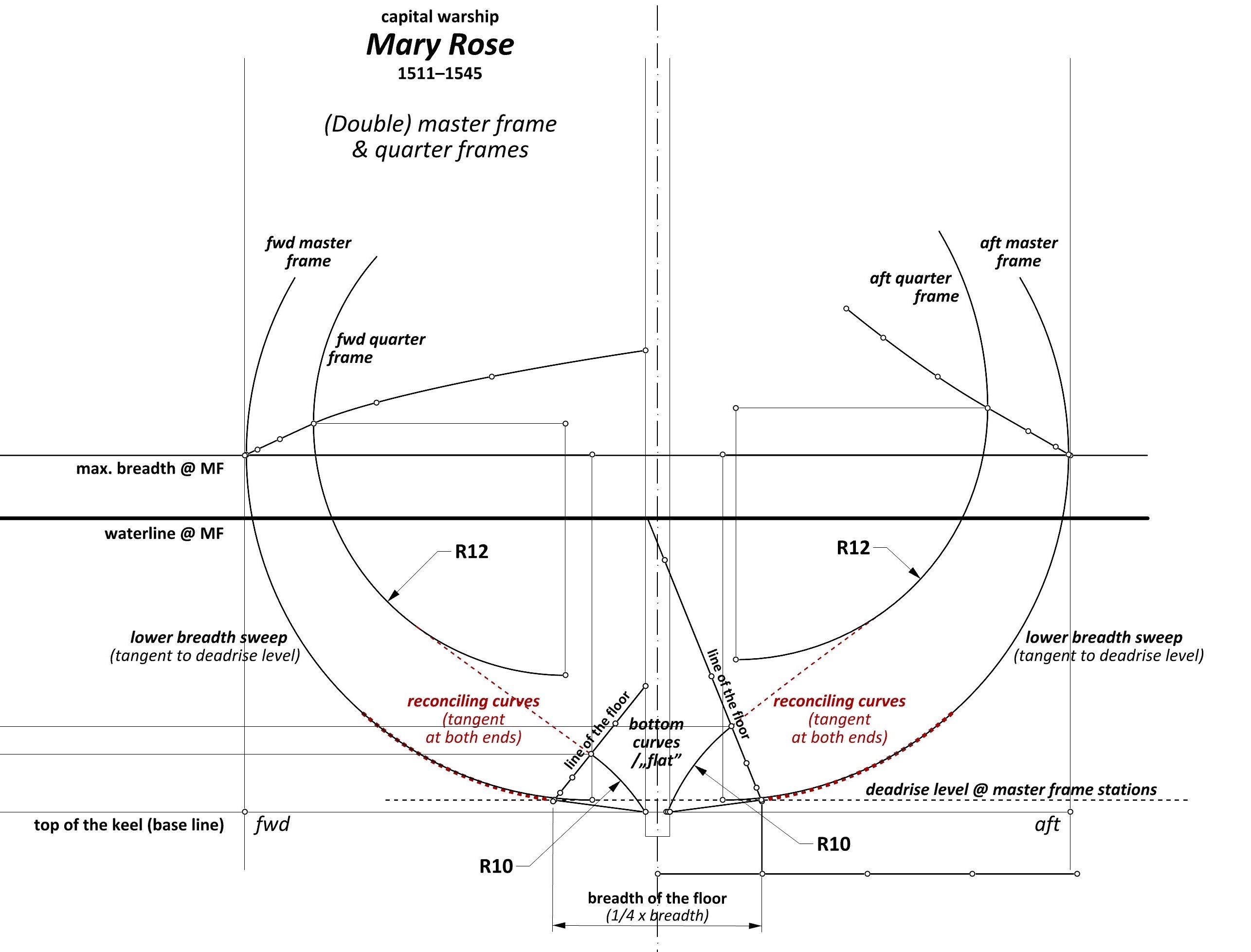
Double master frame & quarter frames Shaping the hull surface starts with defining the contours of the double master and quarter frames, and this step can already easily be carried out straight away on the mould loft, without first drawing these contours on paper. As far as the master frames are concerned, the lines of the bottom/„flat” were first traced according to the corresponding coordinates taken from the line of the floor for the master frame position, followed by the lower breadth sweeps drawn tangentially to the deadrise level for the master frames position, and finally the two sets were joined by reconciling arcs (dashed red), tangentially at both ends (see diagram). Hopefully for greater clarity, the centre and radius of the lower breadth sweep of the master frames can still be described in Martes' words: „take the difference between the deadrise level and max. breadth level, then take this distance from max. breadth horizontally, and that's the center”. In the quarter frames, on the other hand, the bottom curves are arcs (as opposed to straight lines). The radii of the two sweeps that make up the frame contour, i.e. bottom and lower breadth sweeps, were chosen to obtain sharp hull shapes, suitable for warships/privateers, and even necessary for short hulls as well, and at the same time to make the subsequent reconciling curve (dashed red) close to a straight line while maintaining tangency at both ends. For both quarter frames of the Mary Rose, the respective radii appear identical, and are 10 and 12 feet respectively (see diagram). It was important that the surfaces of both quarter frames below the draught line should be similar to maintain the correct longitudinal balance of the vessel, a point clearly made in French shipbuilding manuals of the mid-18th century. This particular method of design, that is, in particular with this specific use of quarter frames (including the subsequent stages described further on), was still being used and described (albeit rather vaguely) as late as 1697 by the Dutch ship carpenter van Yk, and also in the construction of the French ships of Louis XIV's fleet.
-
Mary Rose 1511 — the epitome of the Northern tradition
Waldemar replied to Waldemar's topic in Nautical/Naval History
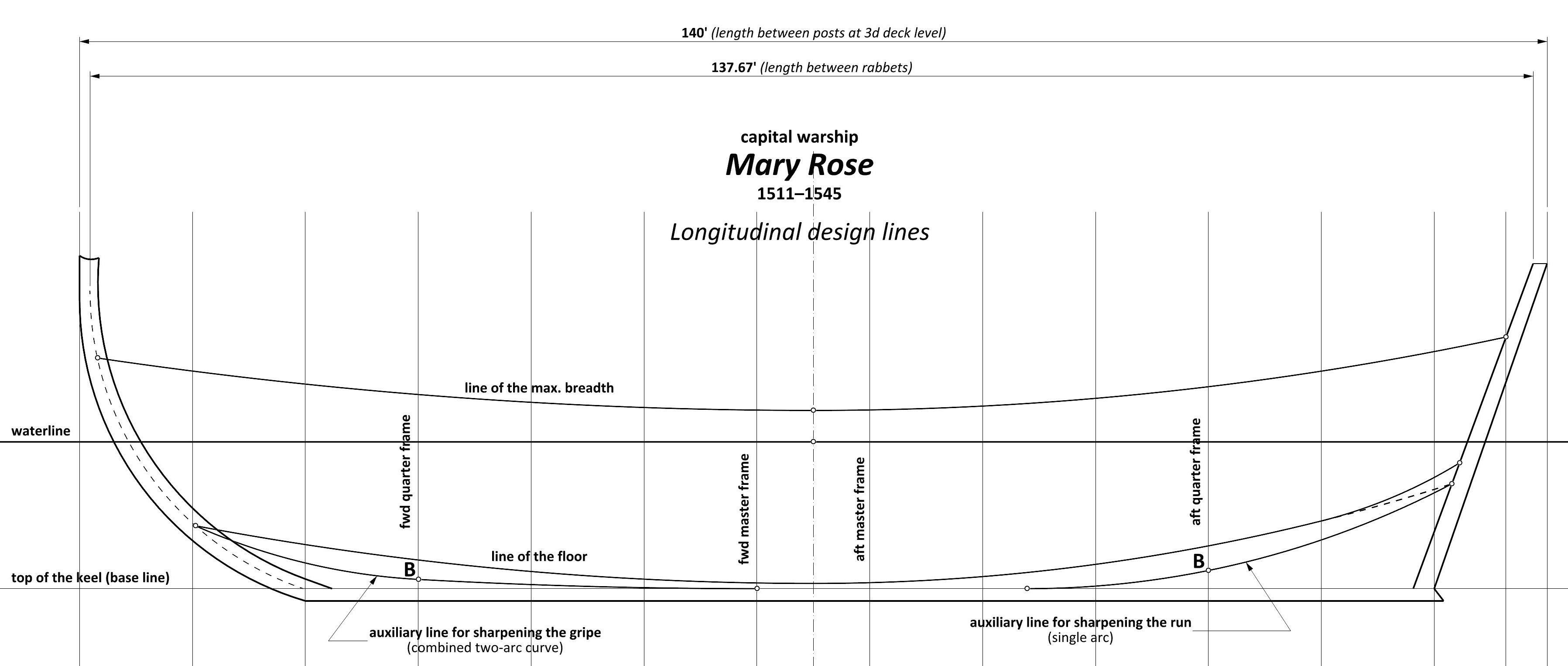
Longitudinal design lines (risings & narrowings) Geometrically, these lines are exclusively single or combined circle arcs. At a later stage, in order to achieve a generally similar run of these design lines, the combined circle arcs will quite commonly be replaced by more advanced curves, such as ellipses or logarithmic curves. The extra rise of the line of the floor at the very end of the stern is actually desired to prevent concave hull surfaces in this region (apart from lifting the flat transom panel out of the water for hydrodynamic reasons), and this is not, or need not be, related to the presumed change in stern configuration during the refit of the vessel. Somewhat anticipating, it can already be said that, conceptually, the Mary Rose exhibits extreme geometric consistency without any anomalies of this kind (assuming, of course, the correctness of the results of this investigation), which practically excludes any local alteration to the ship being made during its life, and especially the lengthening of its keel (according to the hypotheses put forward so far). It is also of note that these hypotheses are probably based only on the circumstance that some of the wreck's components, dated dendrochronologically, revealed newer wood, that is, fitted after the date of the ship's construction in 1511. Yet, the replacement of degraded elements in wooden ships is in itself not unusual at all, especially as the Mary Rose was already a quarter of a century old at the time of her great repair in 1536, which still exceeds the normal lifespan of wooden vessels. In conclusion, there is nothing in the shape of the ship's design lines which seems to suggest any changes to its design during its service.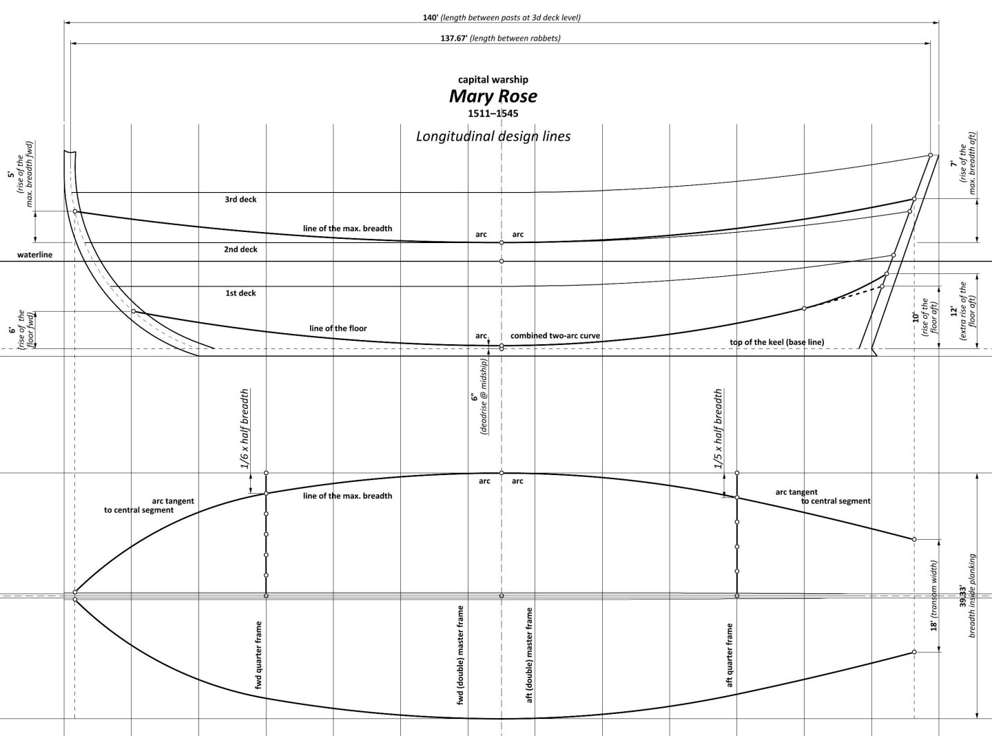
-
Mary Rose 1511 — the epitome of the Northern tradition
Waldemar replied to Waldemar's topic in Nautical/Naval History
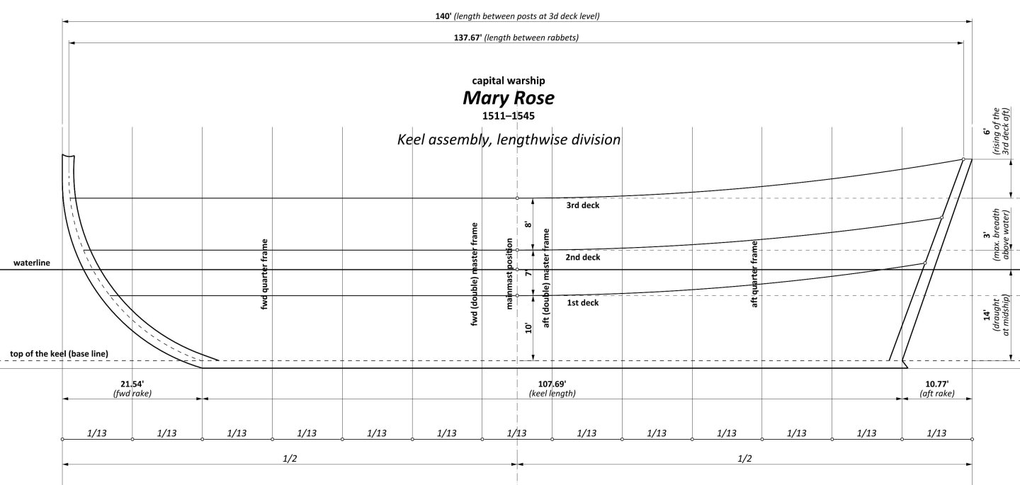
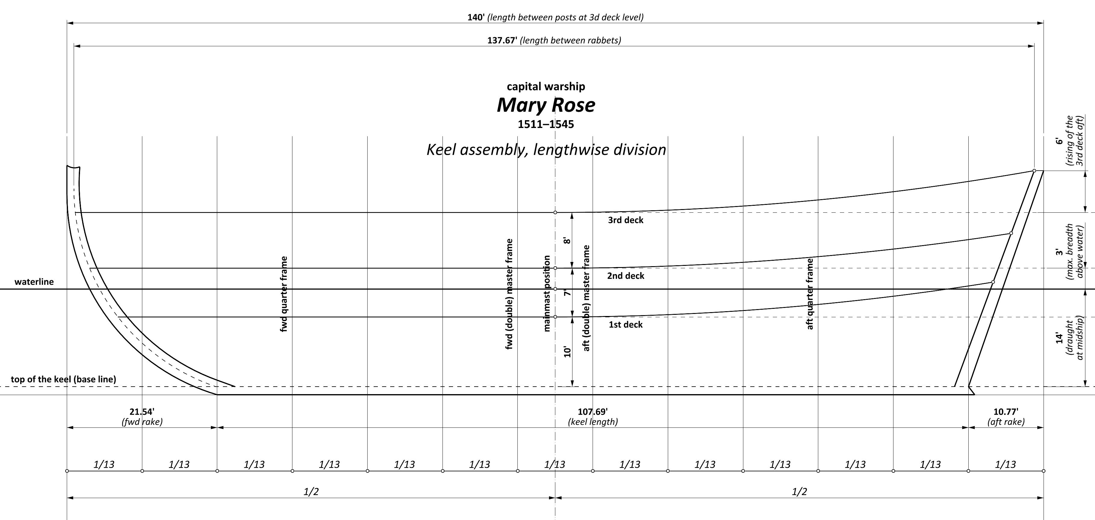
Read or assumed dimensions of Mary Rose 1511: Breadth outside planking – 40 feet Breadth inside planking – 39 feet 4 inches Length between posts (at 3rd deck level) – 3.5 x breadth outside planking = 140 feet Length between rabbets (at 3rd deck level) – 3. 5 x breadth inside planking = 137 feet 8 inches Draught at midship (without keel) – 1/10 x length between posts = 14 feet Height of maximum breadth above waterline at midship – 3 feet Height of 1st deck at midship – 10 feet Height of 2nd deck at midship – 7 feet Height of 3rd deck at midship – 8 feet Rising of 3rd deck aft – 6 feet Lengthwise division (number of equal length segments between posts) – 13 Forward rake – 2/13 x length between posts = 21 feet 6½ inches (21. 538 feet) Aft rake – 1/13 x length between posts = 10 feet 9 inches (10.77 feet) Keel length – 10/13 length between posts = 107 feet 8 inches (107.69 feet) Breadth of the bottom at midship – 1/4 x hull breadth = 10 feet Deadrise at midship – 6 inches Mainmast position – half the length between posts Keel assembly, lengthwise division The base dimension of the vessel – the breadth, being decided, all other dimensions could already have been calculated on the basis of the general proportions commonly used at the time, possibly adjusted by the specific function of the vessel as well as the experience and inclination of the designer. The method of carrying out and the result of such calculations for Mary Rose 1511 is shown above, bearing in mind of course that the values presented here are more or less hypothetical due to the extraordinary distortion of the wreck. The issue of dividing the vessel into 13 equal parts is quite important, as it not only results in specific values for forward and aft rakes, but, even more importantly, sets the stations for all conceptual frames, including the double master frames and both quarter frames (see diagram). The waterline is shown horizontally, however, according to the original design it may have had a trim within 2–3 feet. The mainmast position falls halfway along the entire hull.