.jpg.6c90d67e7e9071af590f4d4a2a8bc908.jpg)
Waldemar
-
Posts
1,003 -
Joined
Content Type
Profiles
Forums
Gallery
Events
Everything posted by Waldemar
-
.thumb.jpg.c6343966b029e7941df5b987d129aac6.jpg)
Mary Rose 1511 — the epitome of the Northern tradition
Waldemar replied to Waldemar's topic in Nautical/Naval History
Thanks. The reconstructed design lines may indeed suggest some modifications to the stern. I'll show what's involved a bit later, in the correct order, as it's probably still a bit early for such details now, and the presentation graphics are not yet ready. -
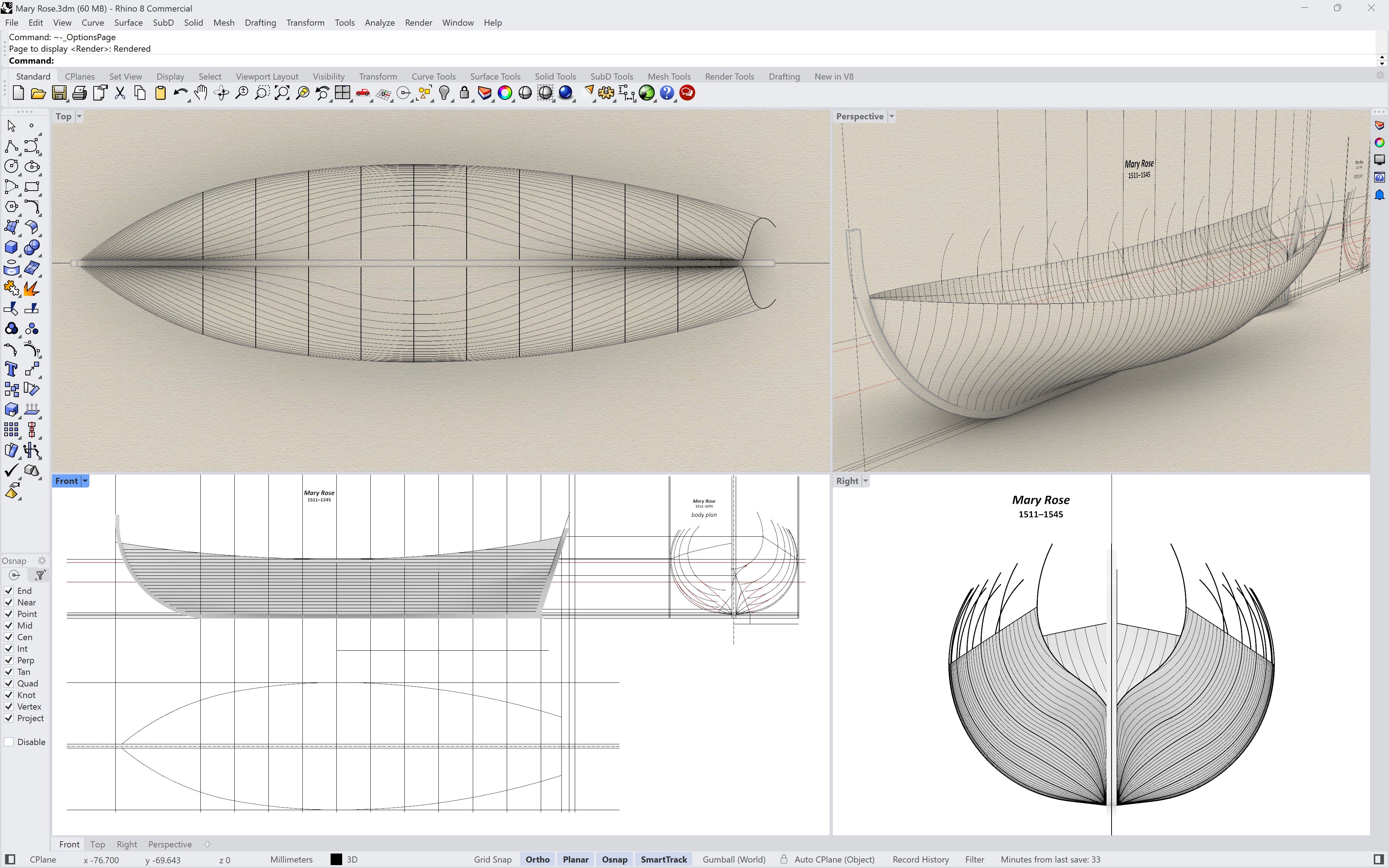
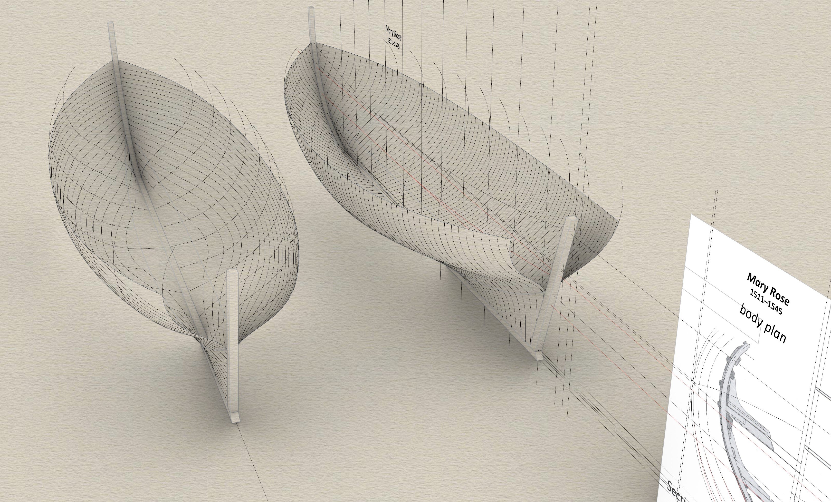
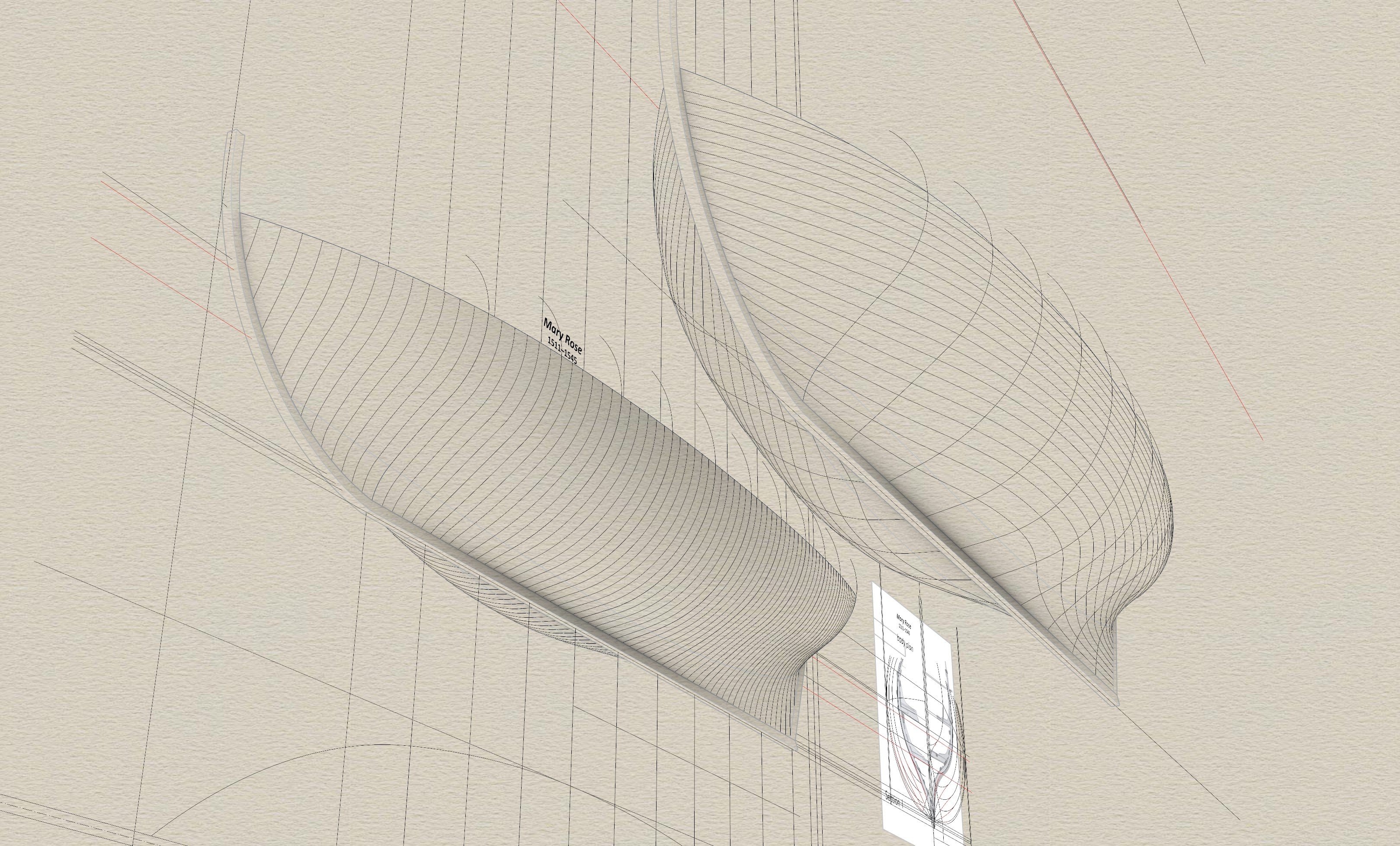
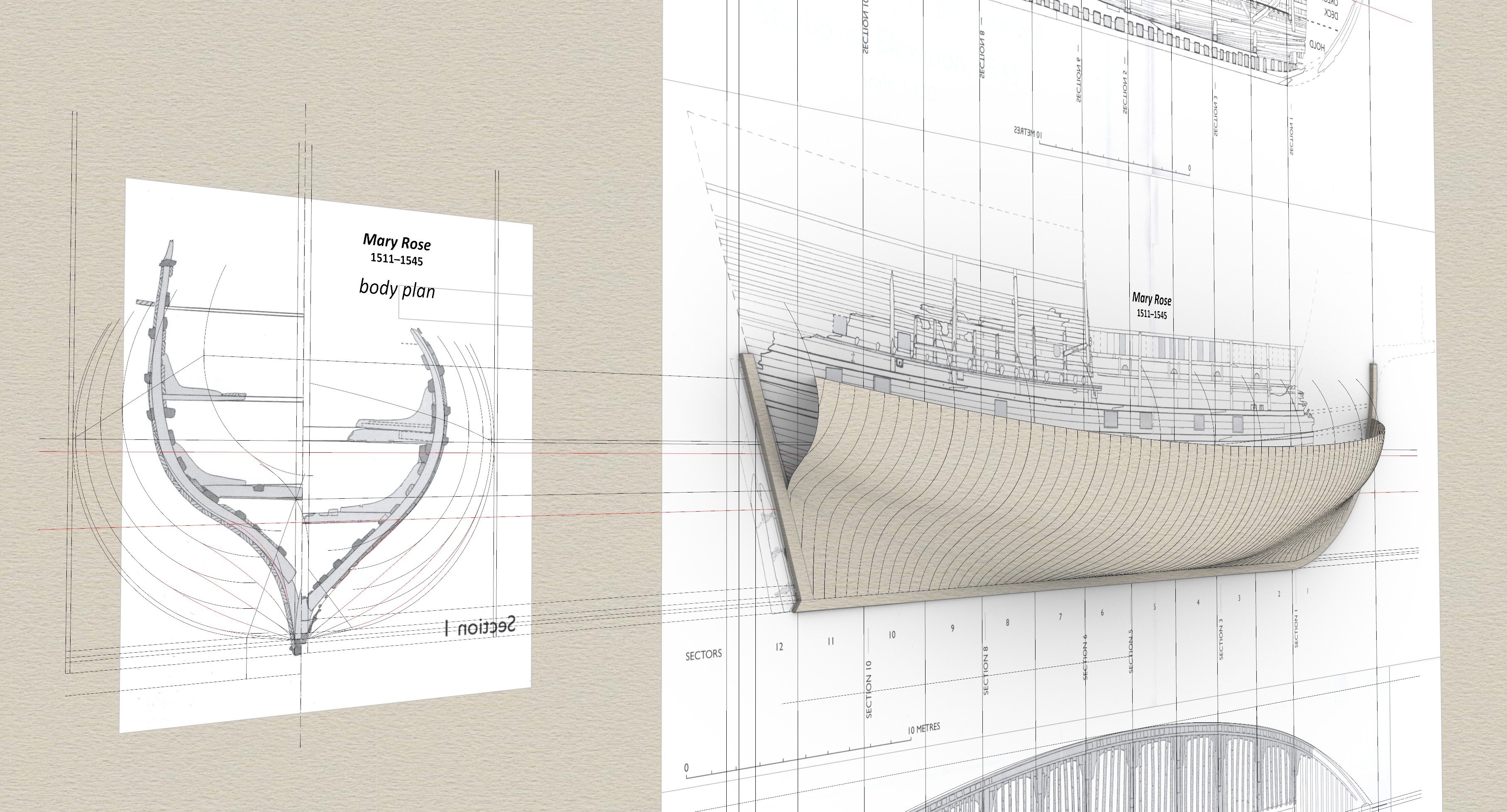
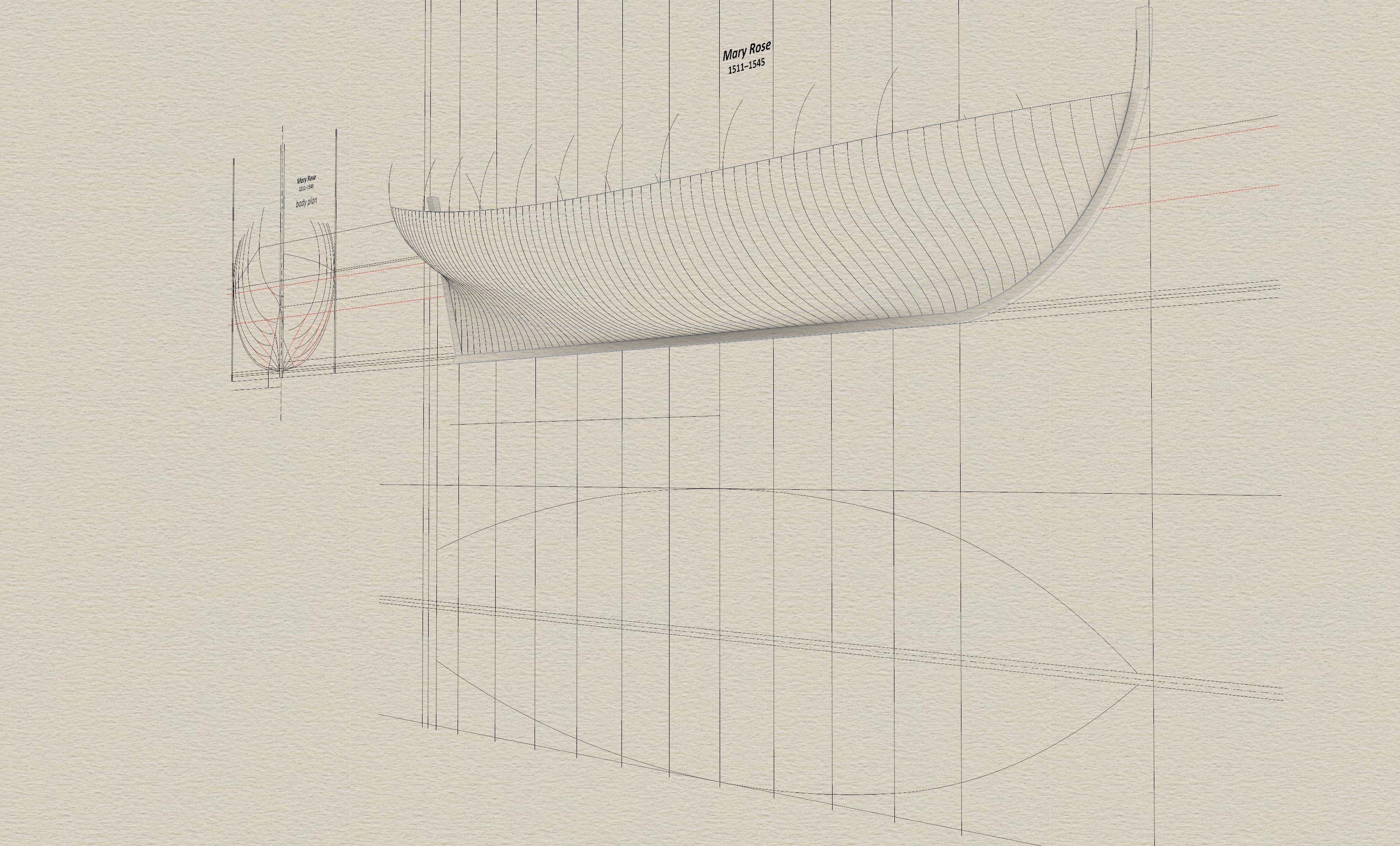
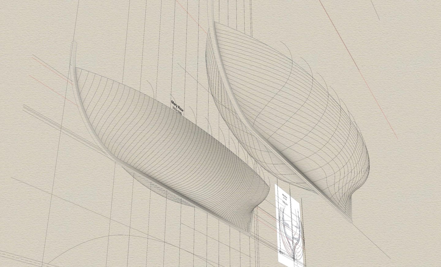
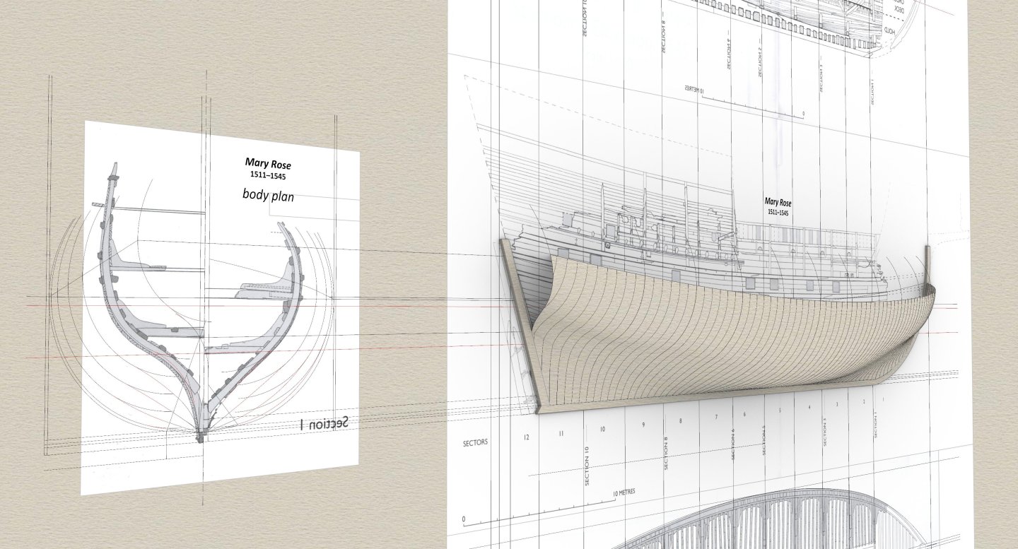
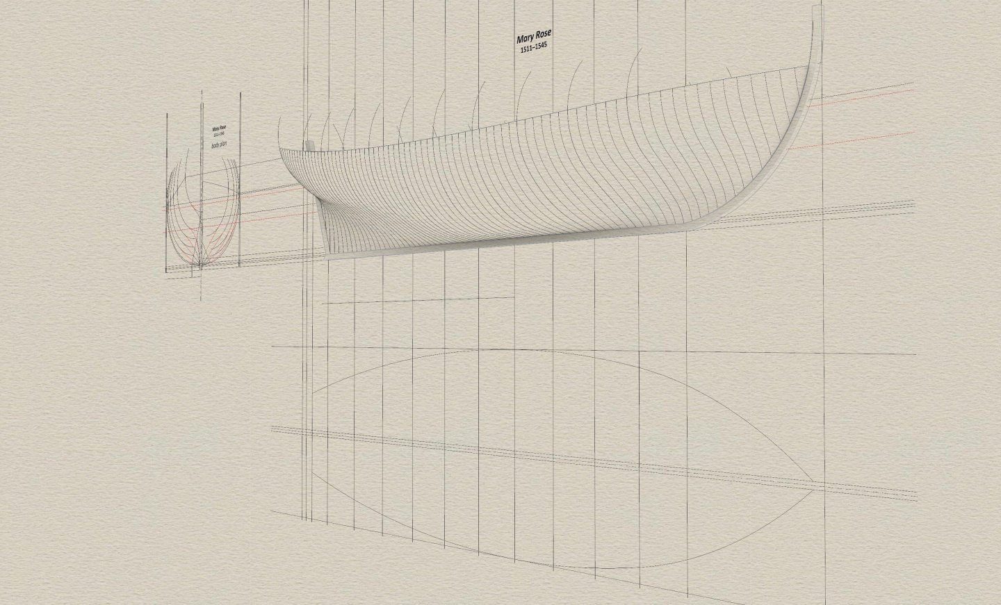
The results of the analysis of the design method applied to the construction of the iconic ship Mary Rose presented here, although perhaps no longer entirely unexpected at this latest stage of investigation undertaken, quite decisively complement and correct previous understandings of the history of shipbuilding in this early period. This case emphatically demonstrates that shipbuilding methods that can be called Northern European (as opposed to Mediterranean) are not, as hitherto thought, confined to the early modern Netherlands, from where they were supposedly spread over time to the other regions of the continent. On the contrary, the increasing number of examples being studied show that this is in fact a building tradition that is omnipresent throughout all northern Europe. Suffice it to say that long after the Mary Rose 1511, an exactly identical design method, with all its specific paradigms, was still applied at least 200 years later, for example, for the construction of the very successful Flemish predatory privateer ships, such as the highly regarded Neptunus of about 1690, and described by Chapman as an „extraordinary sailor”, or vessels of Louis XIV's navy of various sizes, such as the light frigate l'Aurore of 1697 (detailed presentation forthcoming). Even if one is not interested in issues such as the historical context of ship design, familiarity with these methods and the ability to apply them in practice may prove useful to today's authors of reconstructions in order to obtain reliable shapes. It is also worth adding that the ancient design methods, correctly applied, virtually guarantee the immediate fair shapes, without the later, punitive synchronisation of cross-sections, waterlines and buttocks, which was in fact not practised in this early period at all. This particular study is based on the published documentation of the ship in two excellent monographs of the Mary Rose — Mary Rose. Your Noblest Shippe, ed. Peter Marsden, 2009 and Tudor Warship Mary Rose, author Douglas McElvogue, 2015. In contrast, one need only caution against the disastrous in content and effect chapter ‘Hull Design of the Mary Rose’ in the first of these monographs, both in a general sense and for me personally. The attempt there to reconstruct the Mary Rose's design method seems to have led to an even more distortion of the lines of the shipwreck than nature has done in 500 years, which consequently led me astray earlier and a lot of time was wasted to finally sort things out. As always, I could also count on the invaluable help of my friend Martes. So much for the introduction, and before the actual detailed explanations, here are a few welcome renders showing a graphical overview of the results obtained:


-
HMS Anson (1781) in Blender
Waldemar replied to willard48's topic in CAD and 3D Modelling/Drafting Plans with Software
A very attractive effect. To be honest, I personally even prefer such a more or less monochrome convention. It allows a better focus on shapes and structure, modelled, after all, with such care. -
👍 Apart from the occasional printing errors (usually unintentional rescaling of graphics, one or two dimensional) and subsequent possible distortion of the paper, inaccuracies and errors in the original drawings themselves are quite common, especially when drawn by hand, but can also occur in computer CAD drawings if the software operator is not disciplined enough. Unfortunately, this has to be taken into account even when dealing with first class plans, otherwise problems will arise later if not checked beforehand.
- 139 replies
-
- 3
-

-
- ancre
- Bateau de Lanveoc
- (and 2 more)
-
Yet Another Pandora 3D build
Waldemar replied to herask's topic in CAD and 3D Modelling/Drafting Plans with Software
Many thanks, Denis, for the demonstration. I was particularly curious just about this stage of model creation. I think it is enough to appreciate the essence of your methods, indeed so closely linked to the specifics of the software. Once again — great results . -
Yet Another Pandora 3D build
Waldemar replied to herask's topic in CAD and 3D Modelling/Drafting Plans with Software
Thanks a lot for the explanation, Denis, but to be honest, I wasn't referring to the mesh density of the 3D objects already made (for display, rendering, printing, etc.). Rather, I was referring to the prior stage of modelling the shapes of the ship's components sporting, after all, extremely complex geometry, and yet in such a way that all those thousands of components fit together perfectly (at least that's how I see it in your renders), taking into account all those carpenter's mortises and tenons etc., while still maintaining the rigour of the required shapes, individually and as a whole. I know that even in specialised CAD software, modelling such complex structures is very difficult, and I was curious to see what it looks like in Blender, just for the sake of comparison. And, it's absolutely clear that you are fully comfortable with Blender, as can be seen by the results you get . -
Yet Another Pandora 3D build
Waldemar replied to herask's topic in CAD and 3D Modelling/Drafting Plans with Software
Normally I pay attention to that too, but in this case it's all very carefully done indeed, especially compared to some wood models where the grain can run completely perpendicular (and quite absurdly it has to be said ) to the contours of the frames or other proportionally elongated elements. I'm rather puzzled by something else — is a mesh based 3D modelling program (as opposed to NURBS geometry) really optimal for such magnificently detailed structural models and yet of such extremely complex geometry for most components? -
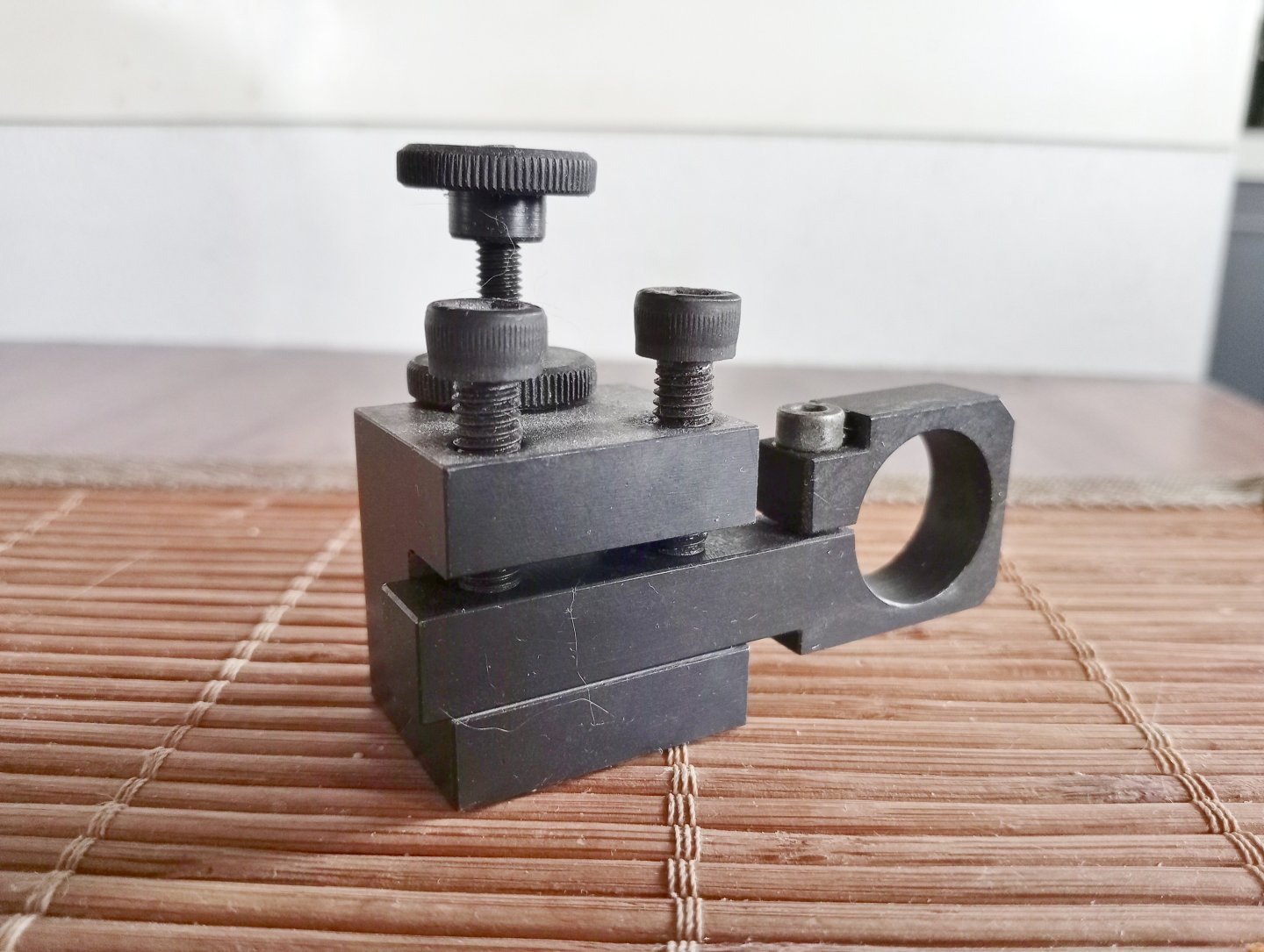
Rightly so. Resistance to side loads and minimal runout are critical features of these rotary tools, as indeed with all devices of this type, so that drill bits would not make cones in the air, making it nearly impossible to start the hole in the right spot (can be checked if buying personally in a local shop, best at highest speeds). Not to be overlooked are the numerous accessories that Proxxon offers for its rotary tools (e.g. drills presses of different types, router bases, etc., also of good quality straight away from the box or only after a small/easy adjustment). However, there is a detail, probably usually unnoticed or underestimated, for which I additionally appreciate Proxxon's rotary tools, namely the metal (i.e. rigid) neck in the shape of a perfect cylinder with a diameter of 20 mm, which is standard on their entire range of miniature drills. This makes it very easy to make various holders for Proxxon rotary tools yourself, while keeping decent geometry of the whole setup (parallelism/perpendicularity). Below is one of my self-made holders, which in the attached photo is in turn mounted in a lathe toolholder, but can also be mounted in vices, adapted to various accessories (including by other manufacturers), etc.
- 139 replies
-
- 6
-
-

-
- ancre
- Bateau de Lanveoc
- (and 2 more)
-
My experience with Dremel has not been good and my assessment is that the product is highly overrated. The main objections (but there are others) — huge vibration and deafening noise, especially at higher speeds. This is a result of the poor precision of the tool and mainly cheap plastic components. But perhaps the newer models of Dremel rotary tools are a little better, check with your dealer how it actually behaves if you can. For comfortable and precise work, I don't think there's an alternative to Proxxon, at least in the popular sector. Its 'strategic' components are very precise and made of metal. Quiet and vibration-free, even at the highest speeds. That said, the highest possible speeds are not really necessary, medium and low speeds are much more useful, provided the torque is sufficient. The lower the speed a rotating tool can achieve, the better, as it makes the tool truly more universal.
- 139 replies
-
- 6
-
-
- ancre
- Bateau de Lanveoc
- (and 2 more)
-
Thank you, too. Actually, in the broadest terms, all French sets of albums of this kind and from this period can probably be collectively called ‘de Colbert’, since they must have been made at the behest of this statesman. Nevertheless, it has apparently become accepted in French historiography to distinguish between these albums in one way or another for the sake of better precision of the message. I thought you might also like to take advantage of this opportunity. Anyway, I'll try not to bother again, only in a way the question about the rabbet arrangement somehow provoked this activity . And, well, I am quite curious, how will you ultimately decide on the issue of the limber holes?
- 139 replies
-
- 1
-
-
- ancre
- Bateau de Lanveoc
- (and 2 more)
-
Nice description, thanks, although a bit in the style of more puzzles or uncertainty than answers . If it's important, I'd suggest replacing the title of one of the works above, that is ‘album de Colbert’ (which is about the construction of a large warship) with ‘Dessins des différentes maniéres de vaisseaux que l'on voit dans les havres, ports et riviéres depuis Nantes jusqu'à Bayonne qui servent au commerce des sujets de Sa Majesté, 1679’, or briefly — ‘album de Jouve’ or ‘album du Ponant’ (it is assumed that the latter album is most likely the product of someone in Jean Jouve's workshop or just working for Jouve).
- 139 replies
-
- 1
-
-
- ancre
- Bateau de Lanveoc
- (and 2 more)
-
As the classic said: — check once, curse twice...
- 139 replies
-
- 2
-
-
- ancre
- Bateau de Lanveoc
- (and 2 more)
-
As I know life and its diversity, it could probably have been quite variable (for example, more or less fixed/loose planks in different arrangements), depending on the specific use of the boat, especially the type of cargo. In the monograph there is also an example of the same type of boat, although almost twice as big, sporting already a regular deck along the whole length of the boat.
- 139 replies
-
- 1
-
-
- ancre
- Bateau de Lanveoc
- (and 2 more)
-
Hi. Maybe a good idea, too. Anyway, I have looked up the description of the construction of this boat in the monograph and found only this brief, rather unambiguous entry (p. 8): Il n'existe pas de bordage intérieur ou vaigrage, uniquement une sorte de ceinture ou serre croisant les allonges à leur mi-hauteur. There is no inner planking or vaigrage, only a kind of belt or clamp crossing the futtocks at their half-height.
- 139 replies
-
- 2
-
-
-
- ancre
- Bateau de Lanveoc
- (and 2 more)
-
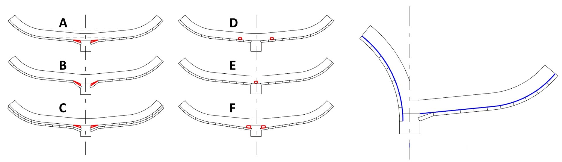
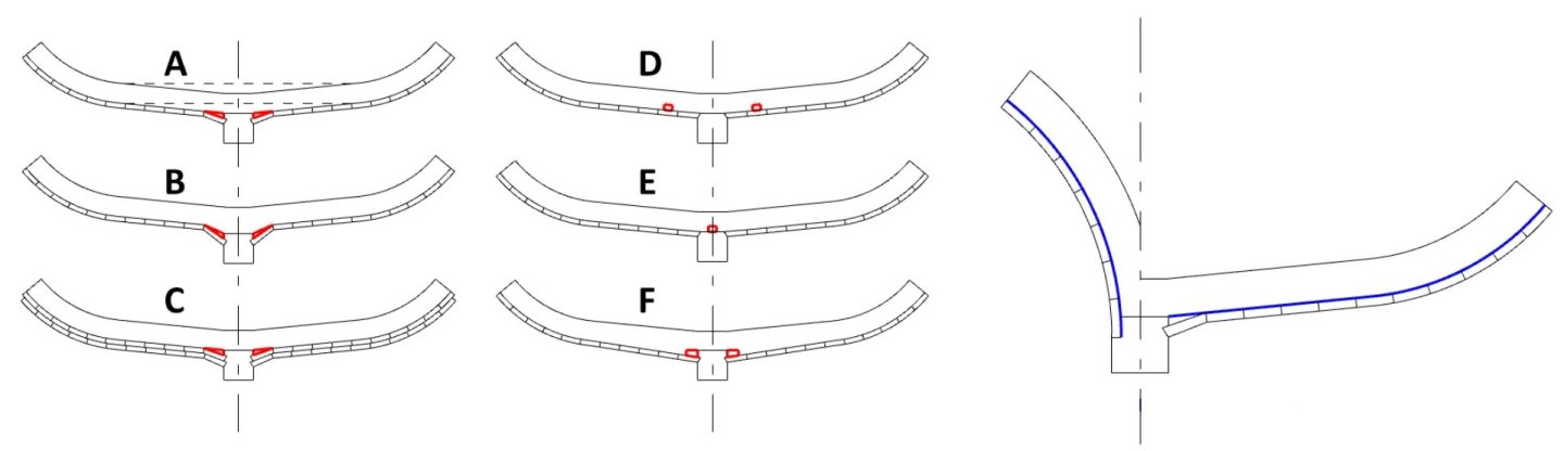
Both variants of rabbet arrangement you show are correct and have been seen on wrecks and plans of various vessels of the period. They are quite closely related to limber holes, which themselves are actually necessary for larger vessels equipped with bilge pumps. This is perhaps a longer story, however, if you consider that this small boat did not have limber holes, you can safely follow the plans in the monograph. Or, if you prefer to have some form of limber holes anyway, you can consider some of the following options for modifications to these plans (limber holes in red).
- 139 replies
-
- 3
-
-
-
- ancre
- Bateau de Lanveoc
- (and 2 more)
-
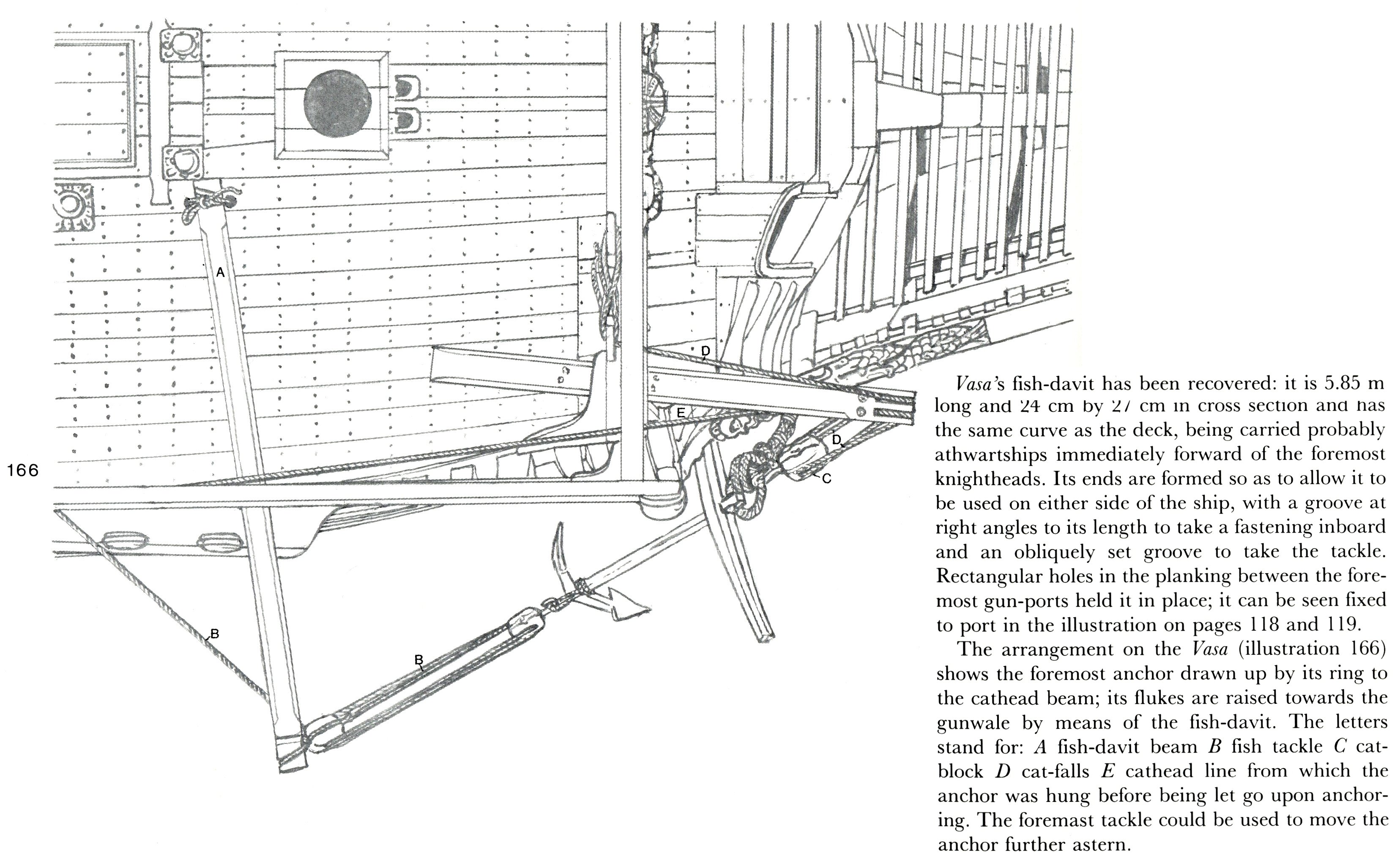
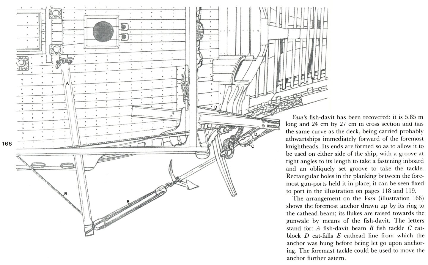
Thank you, Michael, for taking the time to check it out and show the solution here (actually I should have done it myself earlier ). It's quite convincing, especially the period model is very telling. I admit that I probably had in my mind the arrangement known from Vasa 1628 with a shorter and thus more manageable, as it seems, fish davit. With your permission I will recall this arrangement, hopefully it will also prove useful for other readers of your thread (from Landström's The Royal Warship Vasa, pp. 116–117):
- 324 replies
-
- 3
-
-
- Sovereign of the Seas
- Airfix
- (and 1 more)
-
Hi Michael, nice work as usual. Are you sure the fish davit had to be that long? It's probably for verification, but about the length from bulwark to bulwark would do. Then the fish davit could be pulled out one side and then the other. What do you think...?
-
No, no, no... I have meant the diameter of the wooden axletree arm/spindle (of the carriage), and not the the diameter of the barrel's trunnions. The latter is indeed okay in your gun, as you have just shown.
-
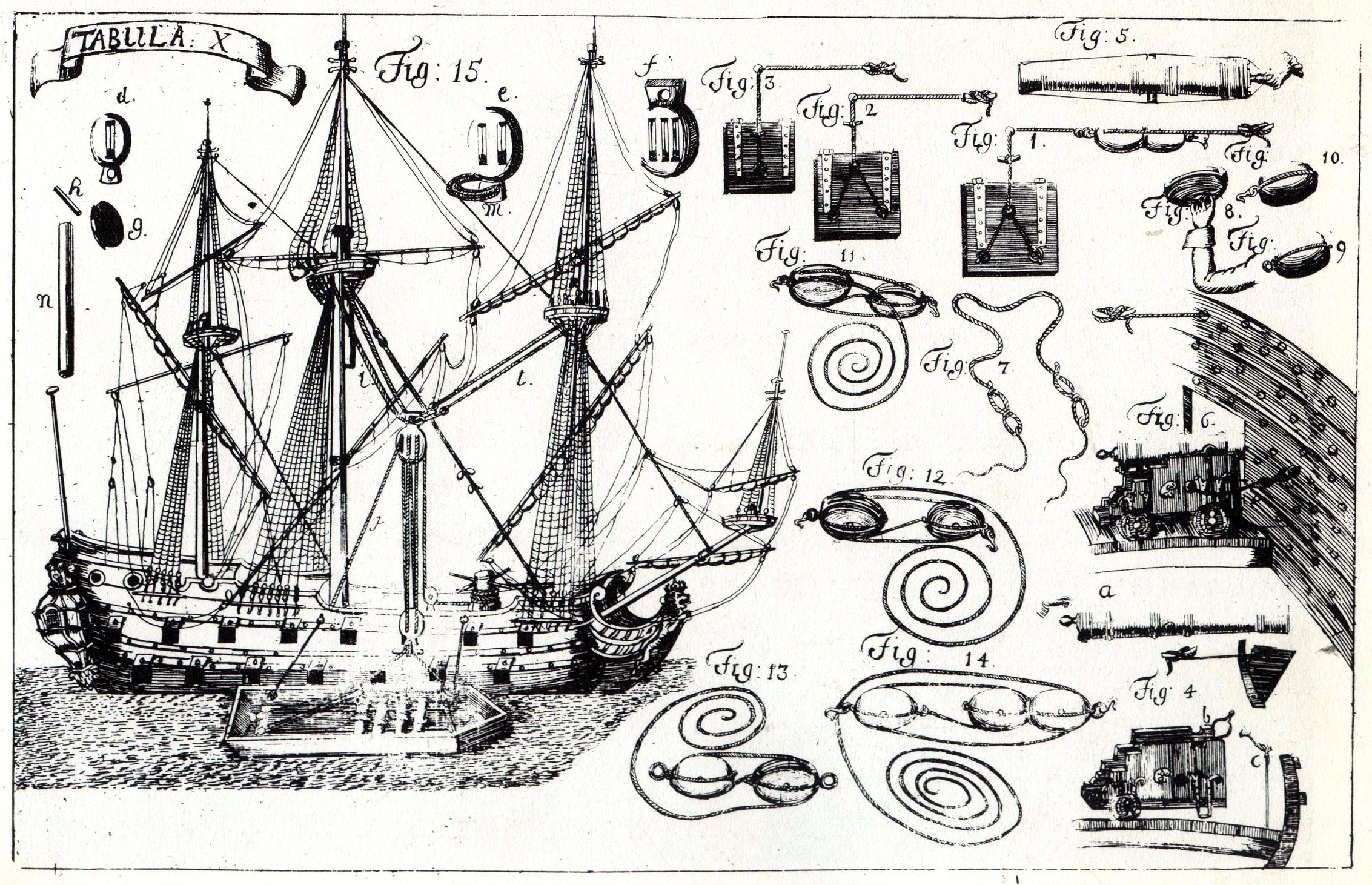
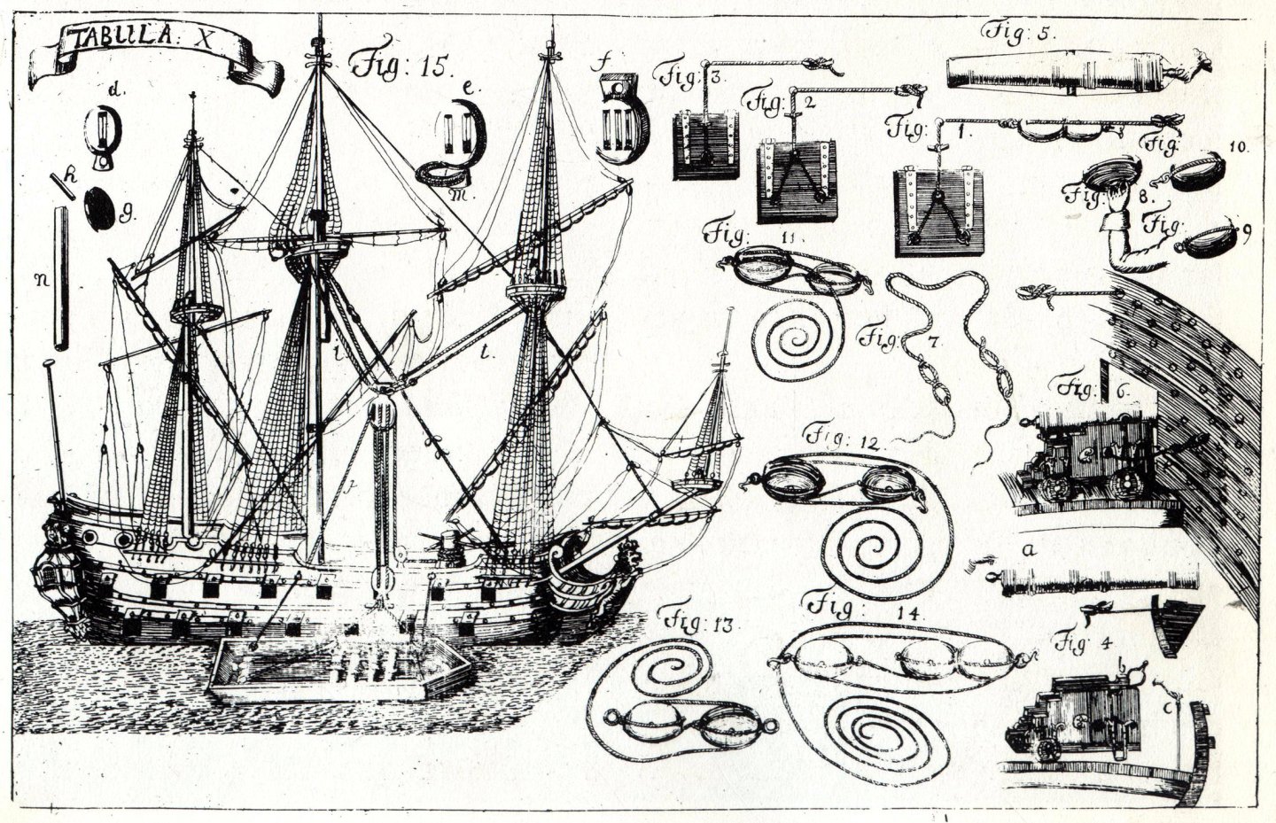
I can only reiterate that the effect you achieved is already sensational. However, if you'll allow me to hint at something, I'd say that, in practice, for the diameters of the trucks, there weren't any ‘standards’ that had to be strictly adhered to; these diameters were simply selected so that the barrel fell in the middle of the gunport. But already the diameter of the axletree arm (spindle) was typically equal to the calibre of the gun, as was the thickness of the trucks. I realise you may already know this, but perhaps such general guidelines may be useful to others. Below is a reproduction from a Swedish work on artillery from around 1700 (D. Grundell, Nödige underrättelse om Artilleriet till Lands och Siös..., Stockholm 1705, Plate X), where in the the lower right corner it is demonstrated how to select the diameter of the (front) truck to get the correct barrel height.
-
An extremely attractive cannon barrel indeed, Hans (and the carriage, too). Is it resin or metal cast? Or 3D print? What's the scale/dimensions? From the authentic looking details I estimate it to be based on a real specimen. All in all, fantastic effect. Congratulations .
-
Well, let's have that consensus . Thanks for the pleasantly correct general appearance already .
-
Judging visually, the original parts from the kit have quite the correct proportions. The usual culprit in such situations is an undrilled bore in the barrel, which shifts the centre of gravity forward a lot. So either you can drill that hole, or fix the gun to the deck with glue, mechanically or both (or some other similar way that will take care of the problem).
-
Oh my... Sorry Olli, but as a lover of old artillery my heart is heavily bleeding... Please bring back the original design of the carriage. That is, the barrel's trunnions just above the front axle, the barrel's base ring above the rear axle (should fall on it preferably in an arc, not vertically), and the trucks of wood only (no metal on the perimeter).
-
Iberian (Basque) Atlantic Whaler ca. 1550 — as, dos, tres…
Waldemar replied to Waldemar's topic in Nautical/Naval History
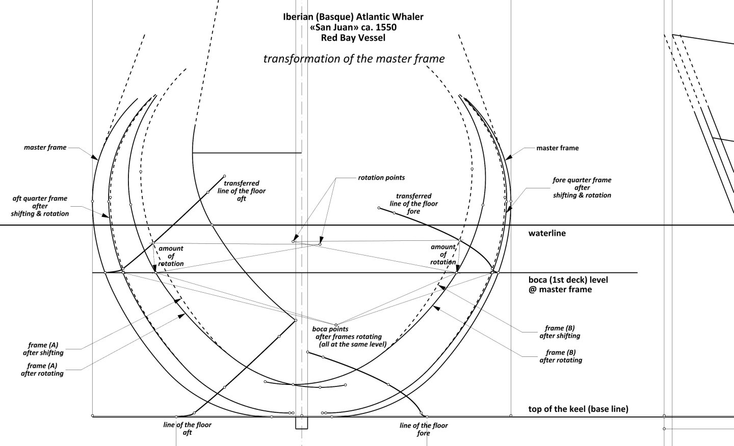
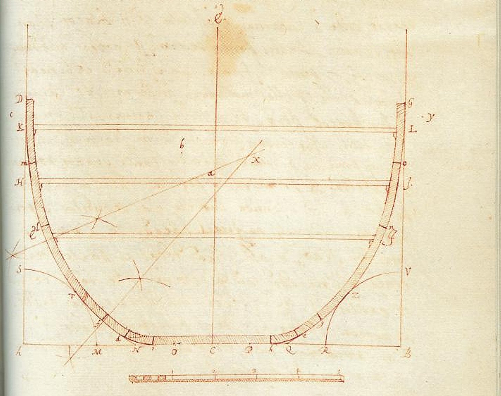
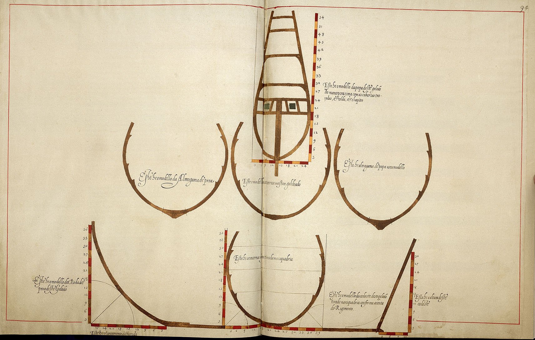
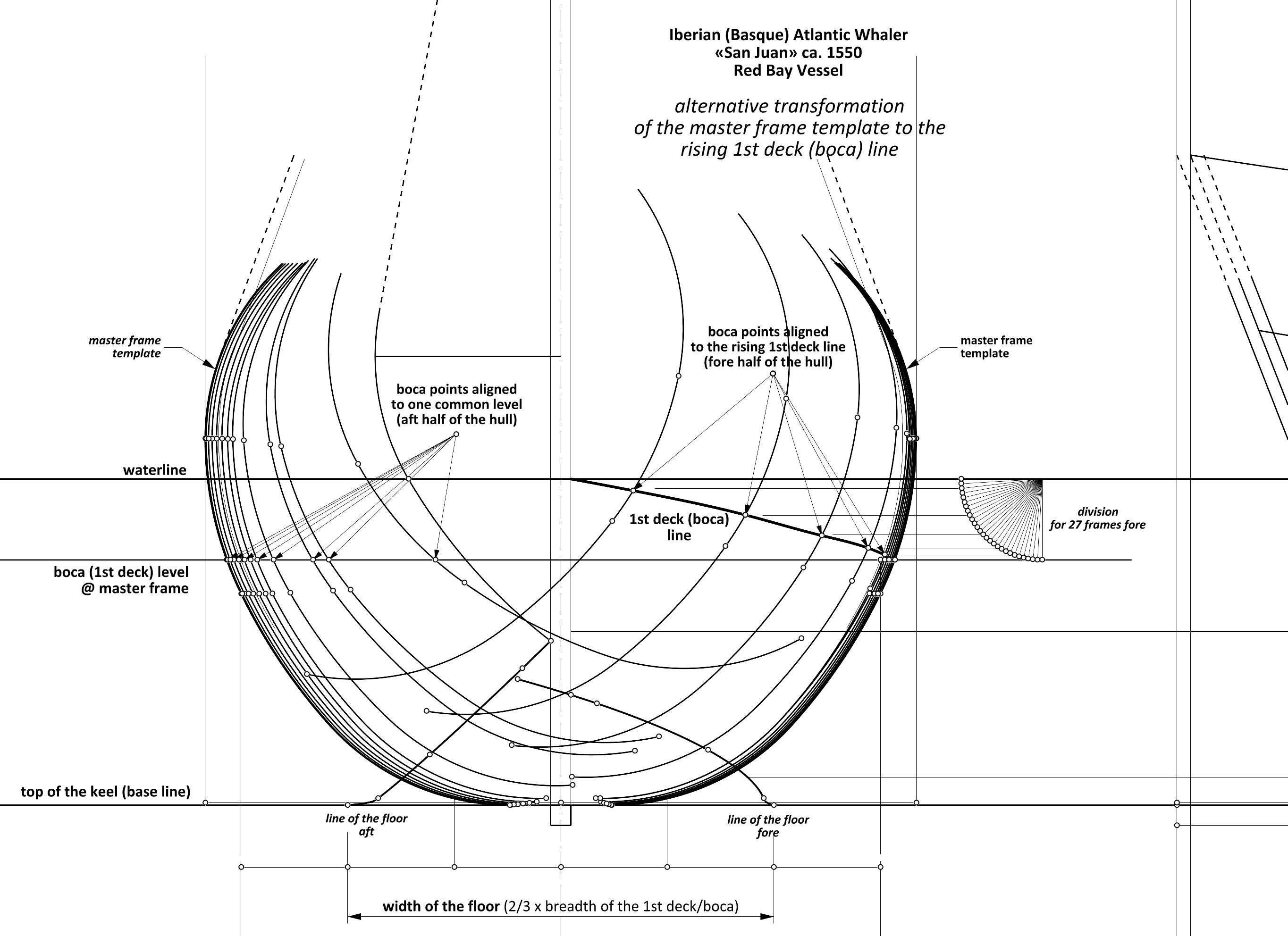
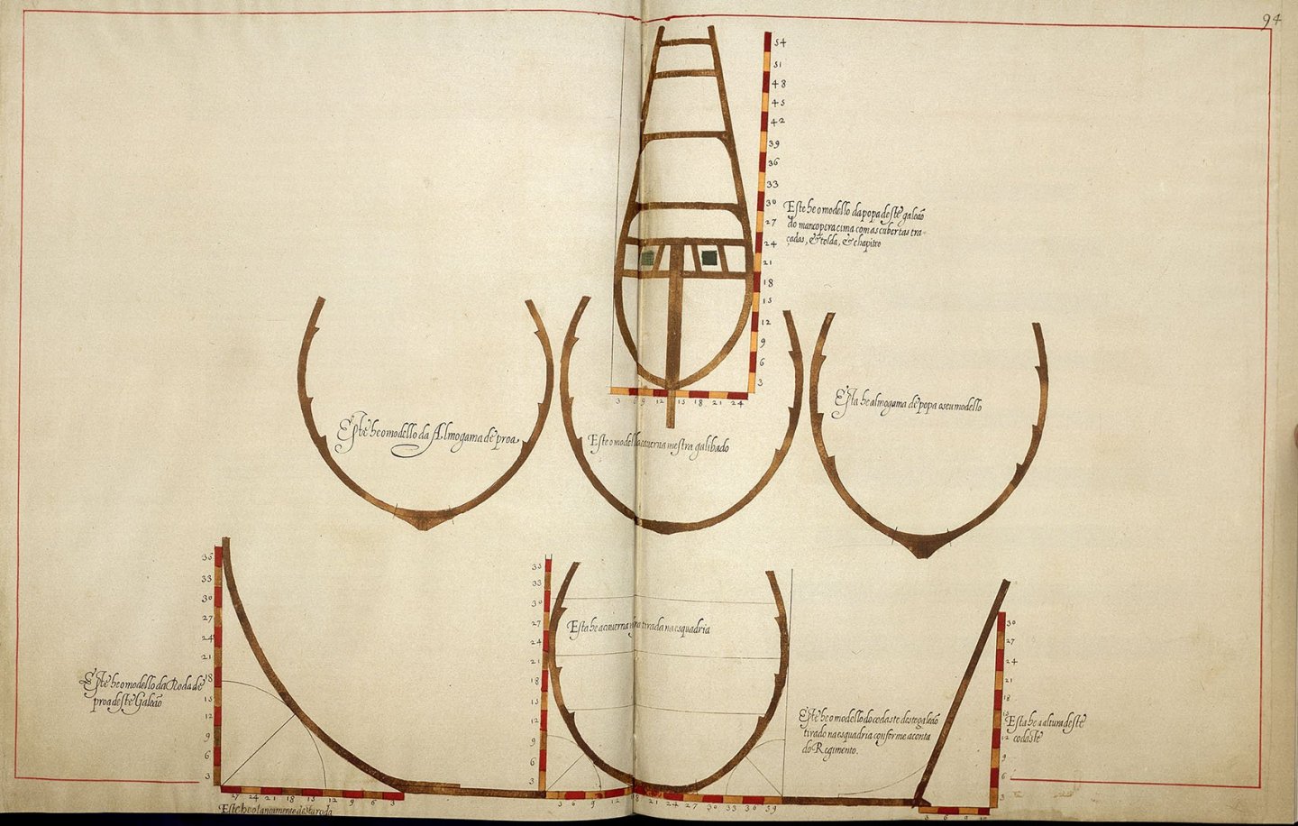
The extant remains of the hull, presented in an otherwise very comprehensive and detailed monograph of the shipwreck (probably missing only an attempt to reconstruct the original design concept of the San Juan), are indeed not overly conclusive. This ambiguity also makes it possible to propose a slightly different, alternative master frame transformation for the fore half of the hull, different from the aft half. The difference is that in this alternative way, while rotating the master frame template, the boca points are not aligned to a single common horizontal line, as shown earlier, but to the corresponding 1st deck height, different for each individual frame. This alternative method, firstly, seems to correspond even better to the archaeological material for the fore half of the hull; secondly, it makes it possible to pre-define (trace on the mould loft) practically all the frames up to the very extremity of the hull, while – importantly – maintaining the condition from the first point; thirdly and finally, it is compatible with written works of the period, such as Livro Primeiro de Arquitectura Naval, ca. 1610 by João Baptista Lavanha or Livro de Traças de Carpintaria, 1616 by Manoel Fernandes. The thing is that both of these works describe and show master frame templates featuring integrated lugs determining the height of the decks (beam heights for one, two or even three decks, depending on the size of the vessel being designed). These integrated protrusions could only determine the height (or rather, in sequence, the rise) of the decks correctly if the boca points were aligned during the rotation of the master frame template to the height of the 1st deck (boca) line, the latter being at different height for each individual frame. Diagram from a work by João Baptista Lavanha, Livro Primeiro de Arquitectura Naval, ca. 1610, showing the contours of the master frame template featuring integrated protrusions marking the height of the decks for all subsequent traced frames: Diagram, showing analogous protrusions, from the work Livro de Traças de Carpintaria, 1616 by Manoel Fernandes: Such a way of aligning the boca points, to the rising 1st deck (boca) line, could in practice be very easily implemented immediately on the mould loft by employing one of the variants of the mezzaluna, preferably the best approximating the geometrically correct arc of the circle (for example, the graminho de beesta, as it is called by Fernando Oliveira), or by successively measuring the individual heights of the 1st deck (boca) line for each frame on the drawing. Later in this presentation, when discussing perhaps the most interesting issue of hollowing/bottom curves, the lines of the hull body proper of the San Juan will follow both of these ways, that is, for the aft half of the hull the boca points will be aligned to the one common horizontal line, and for the fore half the boca points will be aligned to the rising 1st deck (boca) line, as shown in the diagram below.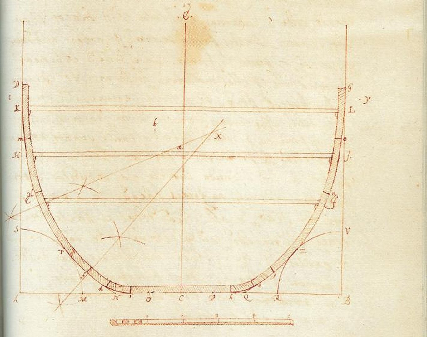

-
Iberian (Basque) Atlantic Whaler ca. 1550 — as, dos, tres…
Waldemar replied to Waldemar's topic in Nautical/Naval History
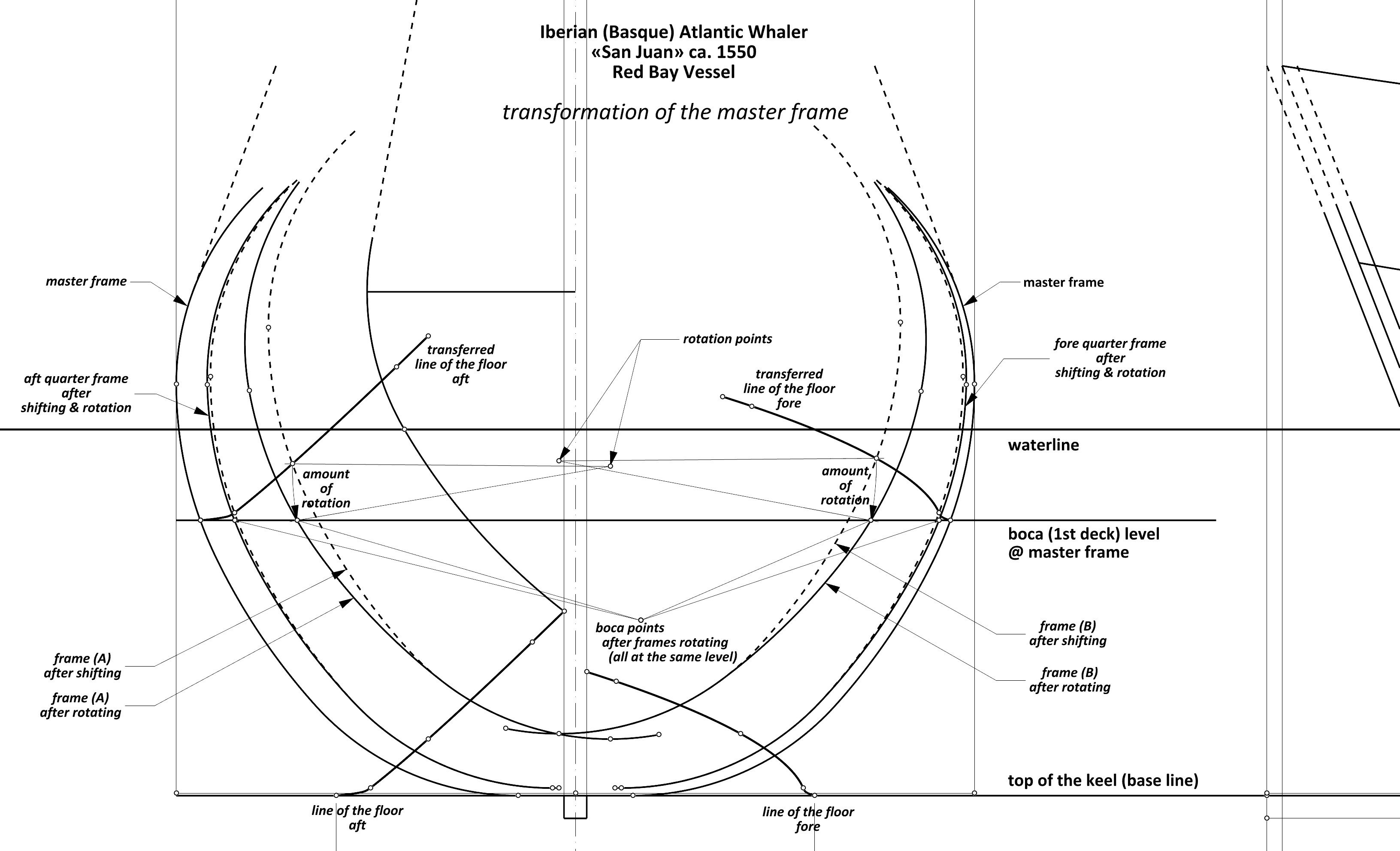
Transforming the master frame – forming the hull body proper To shape the hull body proper of the San Juan, a trivial, perhaps the simplest possible procedure of master frame modification was employed (and at the same time producing the desired results), the essence of which is shown in the diagram below. Apparently, it has not been recognised before and is not yet described in available works, including modern ones. The master frame transformation, which was performed to obtain all the successive, predefined frames of the ship (i.e. almost all, except for the most extreme), was carried out in two separate steps on the mould loft: first, the master frame template was shifted according to the coordinates taken from the intersection of the relevant station lines with the line of the floor. In the second step, the master frame template was rotated in its entirety so that the centre of rotation was the centre point of the bilge sweep and, as a result of the rotation, the boca point was returned to the original level of the boca line, that is, aligning its level with that of the boca point on the master frame. Basically, the method of transformation of the master frame was the same for the central and end segments, except that for the central segments, the shifting of the frames was done according to the geometrical devices of the mezzaluna type shown in the previous diagram, while for the end segments the shifting was done according to the coordinates measured on the ribbands already physically mounted or, alternatively, measured according to the lines in the draught, the latter being more likely in this very case.