.jpg.6c90d67e7e9071af590f4d4a2a8bc908.jpg)
Waldemar
-
Posts
1,003 -
Joined
Content Type
Profiles
Forums
Gallery
Events
Everything posted by Waldemar
-
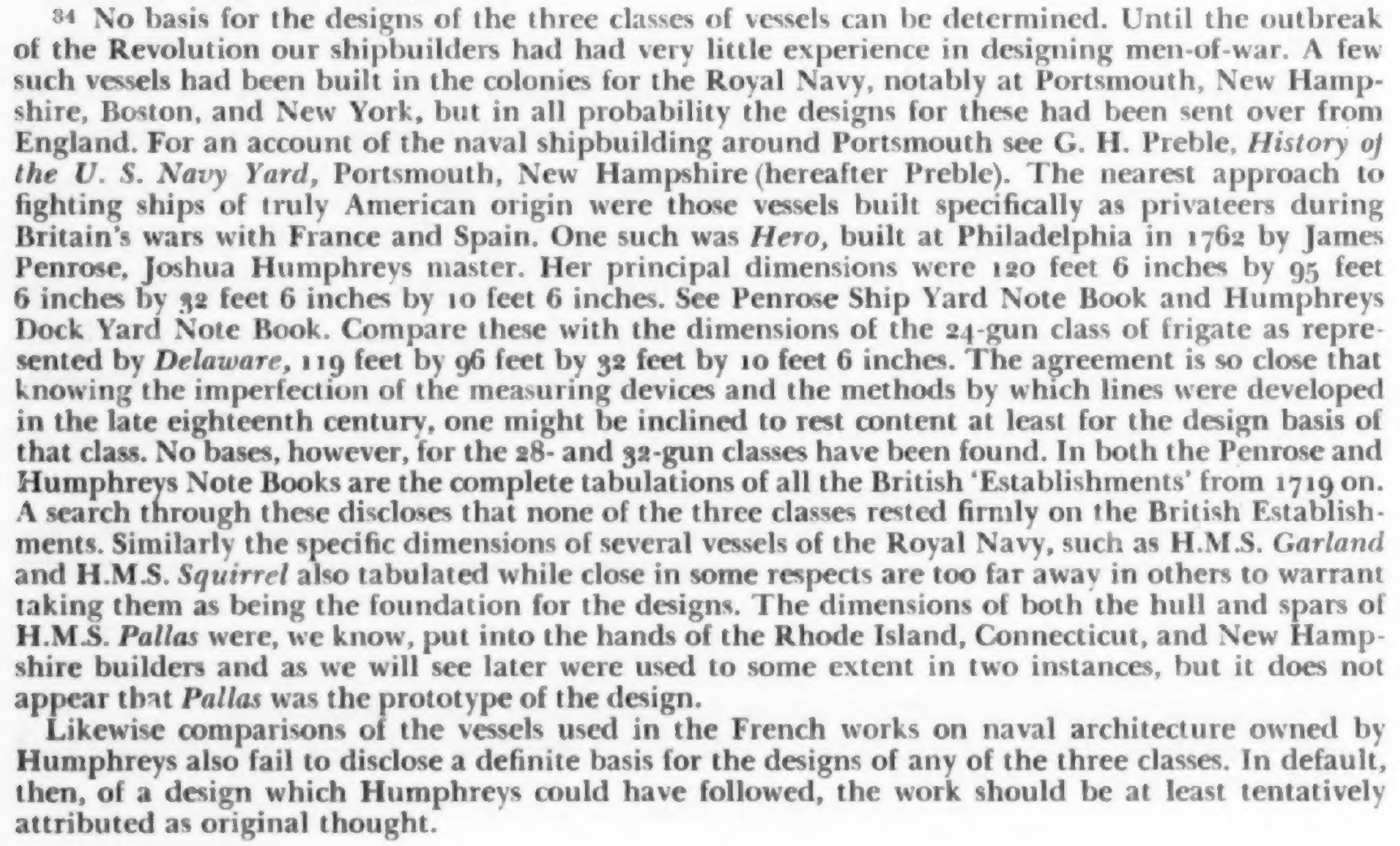
Indeed an excellent article (and easy to find online) — many thanks, Chapman. In a convenient, compact way, it provides information that creates the necessary historical context for this issue. I have also refreshed myself with the content of the related section in The 32-gun Frigate Essex (1799) by Portia Takakjian, published 1990, however, it looks like, that in terms of today's state of knowledge regarding the design methods employed by early American designers, the statement just made by Brewington in his 1948 paper is in fact still relevant:

-
The document is available online for anyone interested (see link below), just only up to page 162 of the manuscript. In a malicious twist of fate, the page with the data for Randolph 1776 is already on the next, first page of the non-accessible part of the whole document, that is 163–164. And the archive wishes USD 37.50 for making one scan of this double page available. Funny. Historical Society of Pennsylvania: DAMS : Volume/Folder : Principal Dimensions [1719-1828] [10581] Under the circumstances, I won't even bother to approach the other archive (the navy) for a better copy of the original ship's plan anymore, and I think I'll give up on this project altogether. It's a pity, because the results and conclusions of this investigation could be really interesting, and actually unknown or unrealized until now. More precisely, I already have near certainty about the design methods applied in early American ships, nevertheless, adequate input material is obviously needed to present this adequately.
-
Thank you, Tony. Yes, I have this publication in my home library, as well as probably all of Chapelle's other major works. Indeed, there is a wealth of interesting, important and useful information about this frigate (actually the whole frigate series) contained therein. Nevertheless, I intend to do something that even Chapelle himself did not do, which is to reverse-engineer the design of the Randolph, and to do this I need a copy of the original design in the best possible quality, as opposed to later redrawings which necessarily distort the original somewhat and, worse, somehow lose very important details found on the originals. By the same token, British-made plans of these early American ships are also unsuitable for my purposes. The point is that I have some observations about the presumed design method used (in a conceptual sense) and I would like to take a closer look at this for confirmation (or otherwise) of these presumptions. They may explain why the American designs were marked by such a specificity of shape rather than another.
-
Thanks, Wayne. Nonetheless, I'm already having some doubts as I've noticed in several places in the document that ‘foremast’ has been reworded to ‘foremost’ (and the other way round) and in addition, for Randolph itself, the distance between decks seems to not match the draught (5‘ 2" versus 5‘ 7"). And, almost forgot, the Randolph is listed in the title as a 23-gun frigate instead of 32-gun one.
-
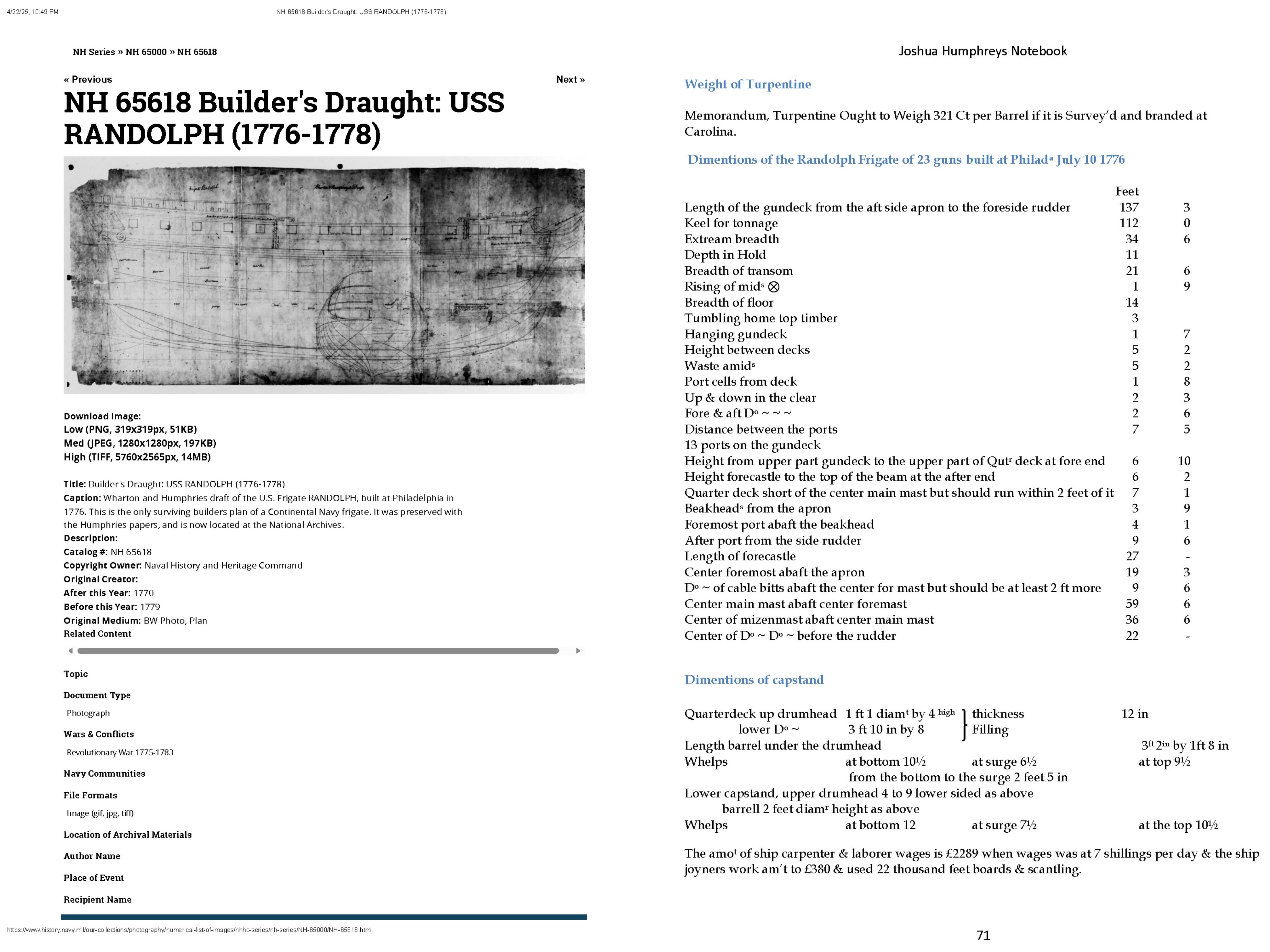
This is most probably the only US ship (frigate) from the Revolutionary period for which original plans have survived. Admittedly, they are available online, but the quality is not the best, as it appears to be essentially a scan of aged microfilm of not very good sharpness, so a lot of the detail is blurred. Does anyone have a better copy than the one available on the archive website? In addition, does anyone have and can provide a good quality scan of a page from the Joshua Humphreys' notebook concerning this very frigate? Granted, this page is already transcribed and available (as is the entire manuscript), but I would nevertheless like to verify the numerical data, which is quite easy to get wrong in the process. Besides, what does the term ‘hanging gundeck’ mean? The stated value on the transcribed page is 1 foot 7 inches. The copy of the draught itself available at: https://www.history.navy.mil/our-collections/photography/numerical-list-of-images/nhhc-series/nh-series/NH-65000/NH-65618.html And reproductions of both mentioned above items:

-
.thumb.jpg.c6343966b029e7941df5b987d129aac6.jpg)
Mary Rose 1511 — the epitome of the Northern tradition
Waldemar replied to Waldemar's topic in Nautical/Naval History
Thank you also for that last entry, Trevor. Some interesting, previously unknown details, giving useful context and enriching the overall picture. As for your reservations about your text, well, that's my personal experience too, as well as probably that of many authors in the world. I've even accumulated quite a few things that I myself would like to improve on in my past publications, be it paper or on-line, nonetheless one usually doesn't go back to it anymore, just creates new things... There is simply no such thing as absolute perfection and this has to be taken into account. But that's still not at all bad, like completely abandoning further attempts or research. I'm also glad to hear that you've remained a fan of the field despite the different paths your career has taken . -
Mary Rose 1511 — the epitome of the Northern tradition
Waldemar replied to Waldemar's topic in Nautical/Naval History
Oh, also a mention that I am familiar with one of your publication, indeed already decades old, yet still relevant and I actually use it as well. Attached below for convenient access for possible readers. Trevor Kenchington, The Structures of English Wooden Ships: William Sutherland's Ship, circa 1710, 1993: Kenchington Trevor - The Structures of English Wooden Ships - William Sutherland's Ship, circa 1710 - 1993.pdf -
Mary Rose 1511 — the epitome of the Northern tradition
Waldemar replied to Waldemar's topic in Nautical/Naval History
I'll say frankly that I enjoyed the spirit of that post, especially the observation (if I understood it correctly) that for effective puzzle solving in this particular field, even the closest interdisciplinary cooperation, which can work so well in most other fields, may not be enough. The way I see it in practice is that, to oversimplify somewhat, historians usually have no idea about engineering, engineers usually have no idea about history (including the history of shipbuilding), on top of that one still has to know several languages (written period sources!), geometry, know CAD software for the necessarily personally conducted tests, be critical, persistent and enthusiastic, and so on. Ideally, it all just should be in the same head, if possible. And well, yes, I have read somewhere that the term "Fragments of Ancient English Shipwrightry" for Baker's manuscript has been in reality coined by Samuel Pepys a couple of decades later . Indeed, today's translators do particularly badly with Germanic languages for some reason. I don't think I can help much, except that, if necessary, I can sometimes try to describe something in other words, in the hope of a better automatic translation. But that's also one of the main reasons why I generally reduce the volume of text in favour of graphics. -
Mary Rose 1511 — the epitome of the Northern tradition
Waldemar replied to Waldemar's topic in Nautical/Naval History
Nevertheless, I would still like to show a quite fresh paper (a 2023 publication on the very important shipwreck of the Lomellina of 1516), which exemplifies the way in which archaeologists up to now actually evaluate shipwrecks in an attempt to reconstruct their shapes. In the shortest terms, missing conceptual elements, such as the rake of the posts or the rise of the decks, are borrowed from some manuscript of the period that is deemed adequate (which may still be appropriate in itself, albeit under certain conditions), yet further on this attempt is reduced to merely manipulating the cross sections to just get the hull shapes as smooth as possible, and by the modern method of synchronising hull lines, which has little in common with the methods of the era. And nothing more, no effort to deduce the true design method that was actually used by the ship's builders. Personally, I have no objection if someone is satisfied with such archaeological evaluations, however limited in their aims, scope and methods. But by being carried out in such an unambitious manner, they certainly cannot clarify perhaps the most important issues, namely those related to ancient ship design methods. On the other hand, such a state of affairs is also the result of a generally poor level of knowledge in this area, and this, in turn, precisely of the pernicious influence of today's doctrines which, through their misguidedness, have in fact only led to practical impotence or stagnation and a consequent lack of progress in this kind of research. I am thinking in particular of the today's doctrine of shipbuilding by ‘feel’ or by ‘eye’, i.e. with virtually no conception whatsoever (yet so convenient for humanistically profiled scholarship), and the doctrine of the ‘spontaneously or independently born English school of design’ (yet having just been virtually stripped of its alleged ‘evidence’), and this still conceived in a frighteningly orthodox manner. However, just to repeat — if someone is nevertheless satisfied with such a take, there you go. Max Guérout, Beatrice Frabetti, Filipe Castro, Revisiting Lomellina, 1516: The Hull Shape, 2023: Guérout Max, Frabetti Beatrice, Castro Filipe - Revisiting Lomellina, 1516 - The Hull Shape - 2023.pdf -
Oh, and then there's this a kind of very abbreviated variant of the latter work mentioned above in the form of an article in one of the periodicals. Rivera Vaquero Isidro José - Aproximación al sistema de Jorge Juan referido al aparejo de los navíos españoles, 1753 - 2011.pdf
-
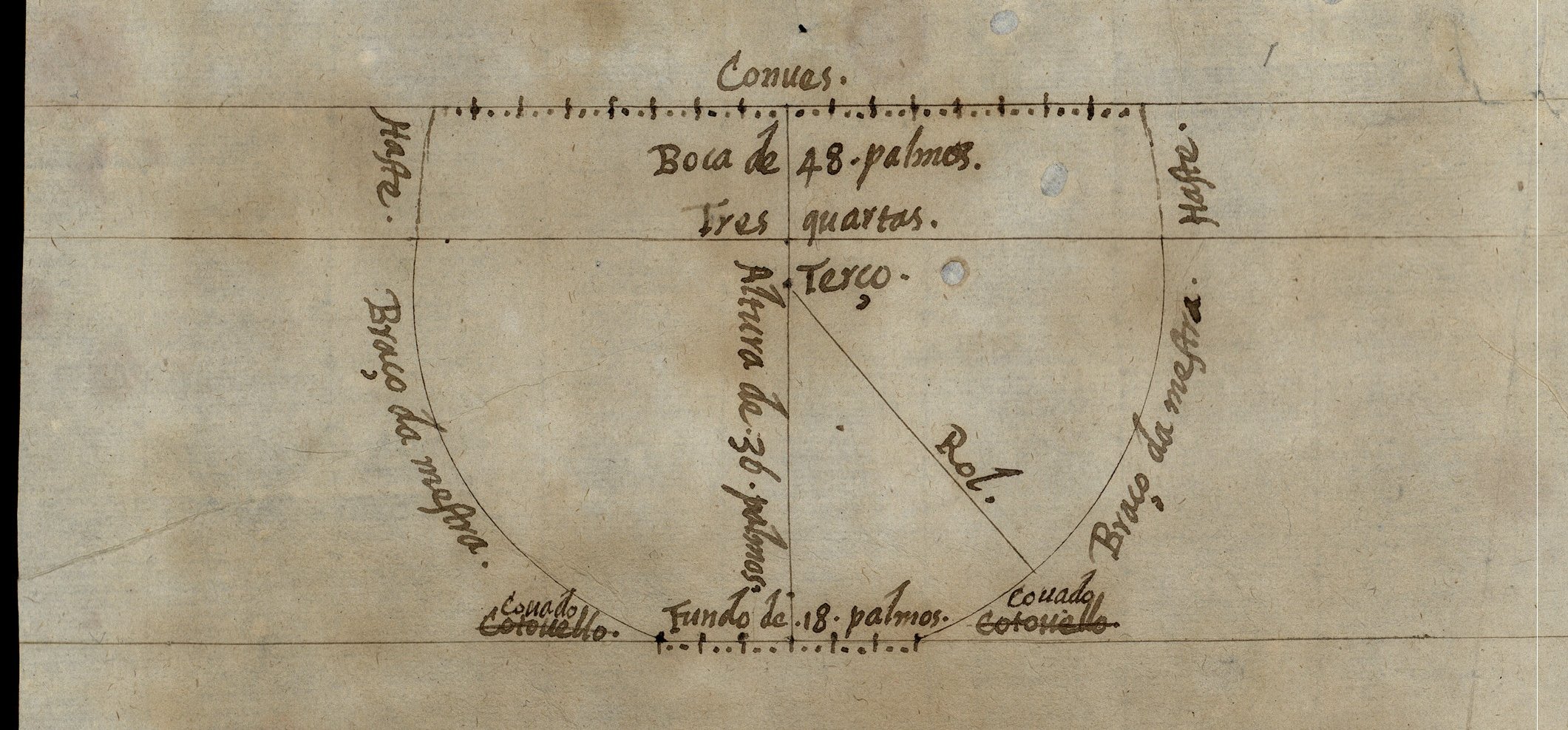
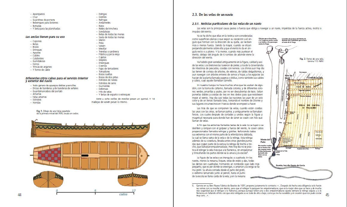
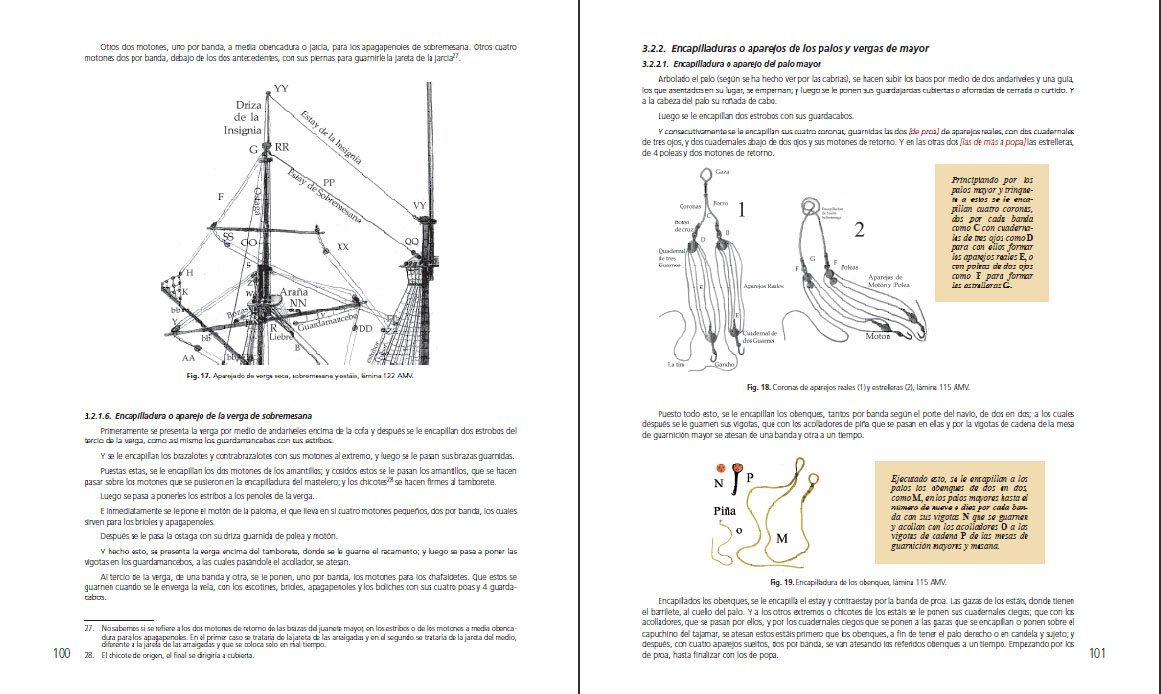
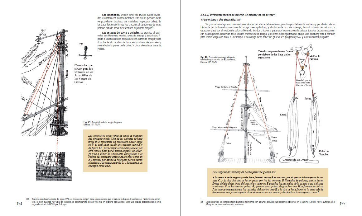
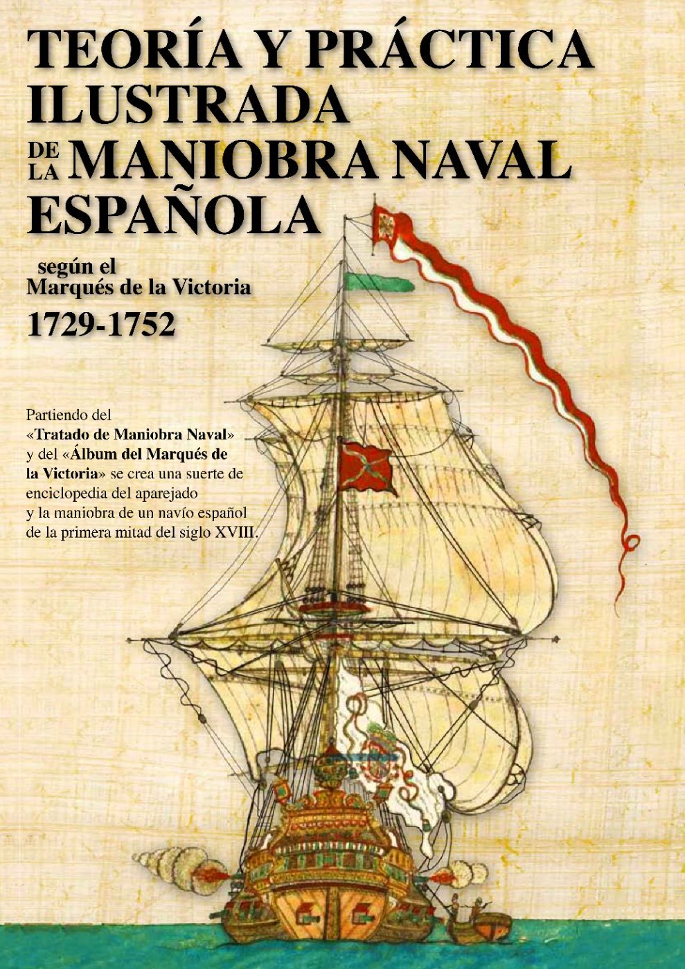
Hello, The excellent sources for the rigging of 18th century Spanish ships are certainly: — Juan José Navarro, Álbum del Marqués de la Victoria 1719–1756, Lunwerg Editores, Museo Naval Madrid 1995, ISBN 84-7782-352-9 On-line alternatives: https://catedranaval.files.wordpress.com/2014/09/mdlv.pdf https://armada.defensa.gob.es/museonaval/aplicaciones/coleccion-marques-victoria/# — Isidro Rivera (ed.), Arboladura y jarcia española de la segunda mitad del siglo XVIII. Compendio Compuesto por: Cartilla Marítima, Santiago Zuloaga 1760 & 1766. Tratado instructivo y práctico de maniobras navales, Santiago Zuloaga 1766 & Reeditada 1806. Reglamento de Jarcia, Marqués González de Castejón 1773, Associació d'Amics del Museu Marítim de Barcelona, Barcelona 2010, B-42878-2010 (includes rope dimensions) On-line alternatives: https://bibliotecadigital.rah.es/es/catalogo_imagenes/grupo.do?path=1006025 https://bvpb.mcu.es/es/catalogo_imagenes/grupo.do?path=151659 — Modelos de Arsenal del Museo Naval. Evolucíon de la construccíon naval española, siglos XVII-XVIII, Lunwerg Editores, Barcelona–Madrid 2004, ISBN 84-7782-959-4 — Isidro Rivera, Joseba Burdain, Jesús J. Adán, Teoría y Práctica Ilustrada de la Maniobra Naval Española según el Marqués de la Victoria 1729–1752, Vagara 2021, ISBN 978-84-09-55974-9 (excellent, detailed explanations, both textual and pictorial, yet without dimensions of the rigging components) Promotional pages of the latter item (by the author):


-
Mary Rose – an English ship of the Mediterranean concept
Waldemar replied to Waldemar's topic in Nautical/Naval History
The conclusions expressed in this thread are out of date, the result, as it later turned out, of a misleading bit of material published in the official monographic publication on Mary Rose. The analysis and conclusions representing my current state of knowledge are contained in the thread: Apologies, and thank you, Waldemar Gurgul -
Mary Rose 1511 — the epitome of the Northern tradition
Waldemar replied to Waldemar's topic in Nautical/Naval History
As a kind of epilogue to this thread, I am also including here a case from another, rather distant part of Europe, nevertheless thematically and chronologically highly relevant to the issue. In 1570, the Polish ruler Sigismund Augustus, intending to build a royal fleet practically from scratch, instead of turning to Gdańsk/Danzig, which, after all, was at the time one of the largest, if not the largest builder and exporter of ships in Europe, but over which he had almost no political control, asked none other than the Venetian doge to send an expert (granted) who could design and build ships. Most telling, however, is the expressed rationale for this request, clearly stating that Venice was second to none when it came to the ability to build the best ships in the entire known world of the time. Or at least that is what was thought at the time. -
Mary Rose 1511 — the epitome of the Northern tradition
Waldemar replied to Waldemar's topic in Nautical/Naval History
I would also like to add, for the sake of greater clarity, that this very issue, in its historical terms and significance, is indeed very closely related precisely to Mary Rose herself, and more specifically to her incomplete, haphazard and simply wrong conceptual interpretation (or rather only a residual attempt at such an interpretation, limited to ‘forceful’ matching of a more or less random arcs to the contours of Mary Rose's frames), published in one of the chapters of Mary Rose's archaeological monograph. Archaeologists themselves, or at least some of them, are nowadays drawing attention to this fatal circumstance, it is just that no one has so far been able to offer a complete yet convincing solution. In addition, this disastrous state of affairs has also been largely contributed to by the failure so far to offer a proper study and publication of Mathew Baker's manuscript, which essentially, as it seems, describes the Venetian methods he learned there. In fact, even the availability of the manuscript itself is so far strictly restricted to only a small circle of interested parties, maybe not without reason. As a result, in today's historiography and consciousness, “classical Venetian methods” are taken for “classical English methods”, and — quite ironically and also misleadingly — the Baker's manuscript itself is even called the Fragments of Ancient English Shipwrightry. I am attaching below a file with published conference materials from 2003, from which one can see just how weak premises today's doctrine on this issue has been based on (apart from the general historical ones, which by the way you cited earlier, the catastrophically wrong conceptual interpretation of the Mary Rose case and a handful of rather naive explanations, or rather speculations, of a conceptual nature). Sadly, this is the result when technical issues are looked at and explained in, shall we say, a predominantly “humanistic” way. In fact, it may be even surprising that nobody has done anything about it so far, at least not in an effective way, but this, I guess, may have been influenced by more than just substantive considerations. Nowacki Horst, Valleriani Matteo - Shipbuilding Practice and Ship Design Methods From the Renaissance to the 18th Century - 2003.pdf -
Mary Rose 1511 — the epitome of the Northern tradition
Waldemar replied to Waldemar's topic in Nautical/Naval History
Thank you very much, Trevor. Yes, a whole series of threads in this area have already been created. The majority of the most mature, and also the most closely related to Mary Rose's case, as they concern the Northern European tradition, are on the sister nautical-modelling forum (easy to find, I believe). All in all, it has been quite a long and difficult road allowing for the eventual breaking free of the overly speculative and yet universally uncritically accepted doctrines of today on this issue. -
Mary Rose 1511 — the epitome of the Northern tradition
Waldemar replied to Waldemar's topic in Nautical/Naval History
Anticipating the end of this thread, I would once again like to thank all those involved, especially Martes, whose comprehensive assistance and on a variety of detailed issues proved invaluable. Waldemar Gurgul -
Mary Rose 1511 — the epitome of the Northern tradition
Waldemar replied to Waldemar's topic in Nautical/Naval History
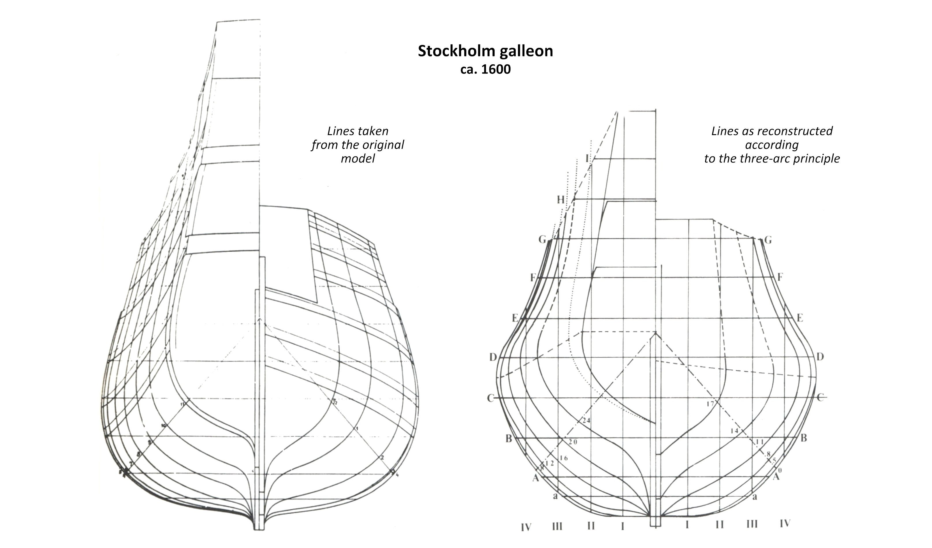
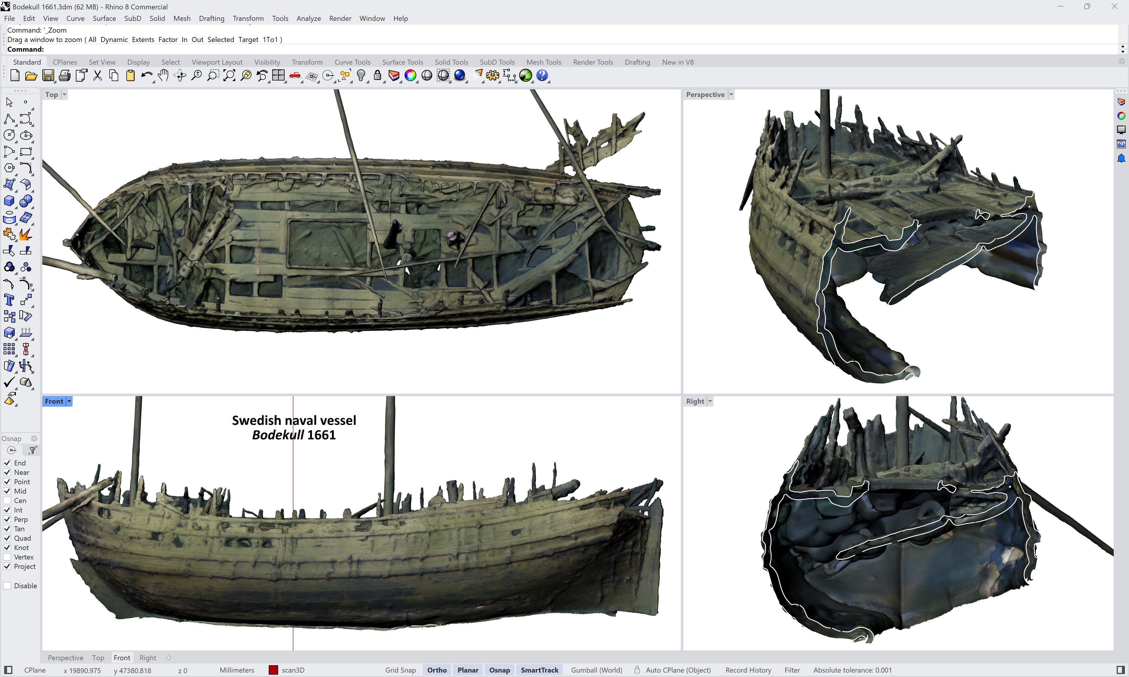
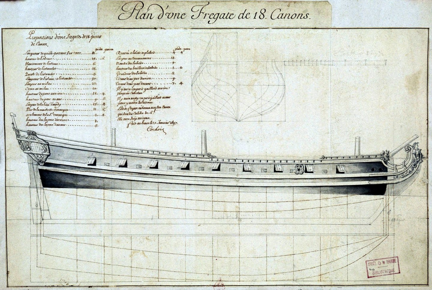
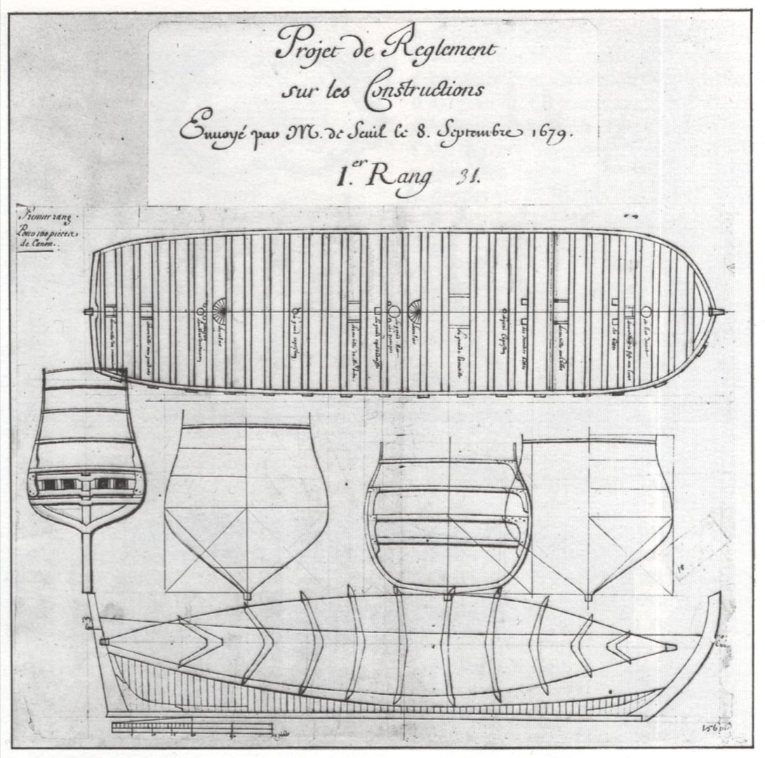
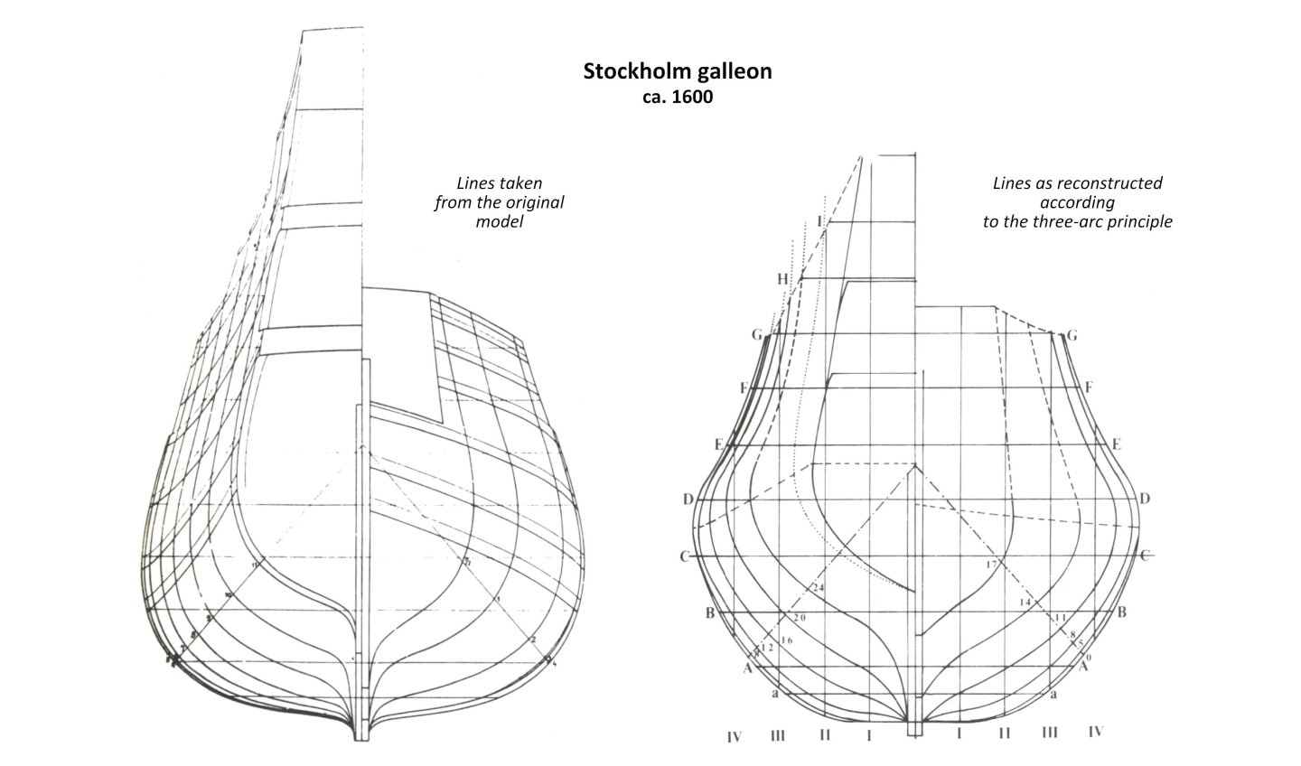
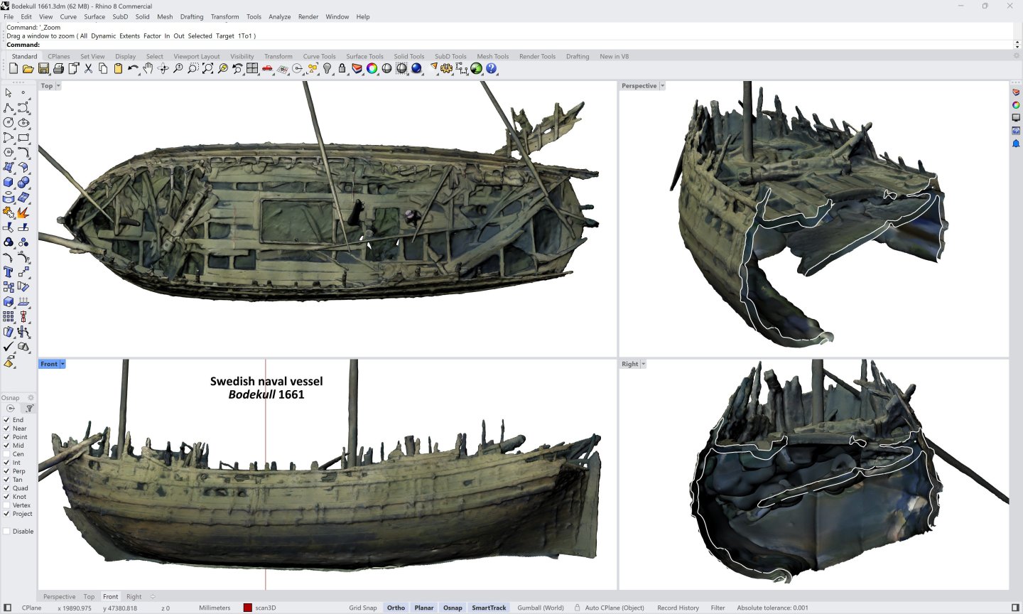
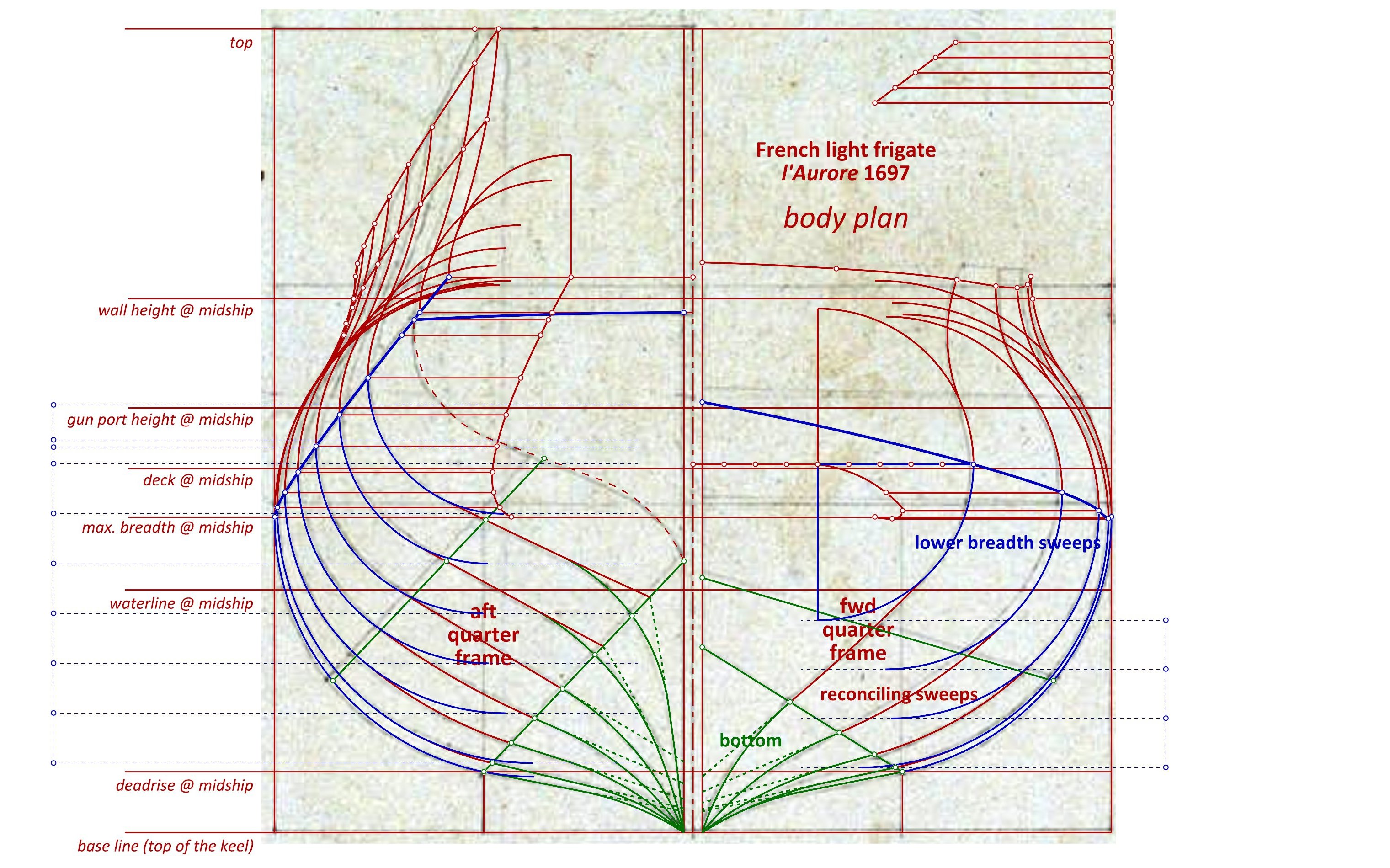
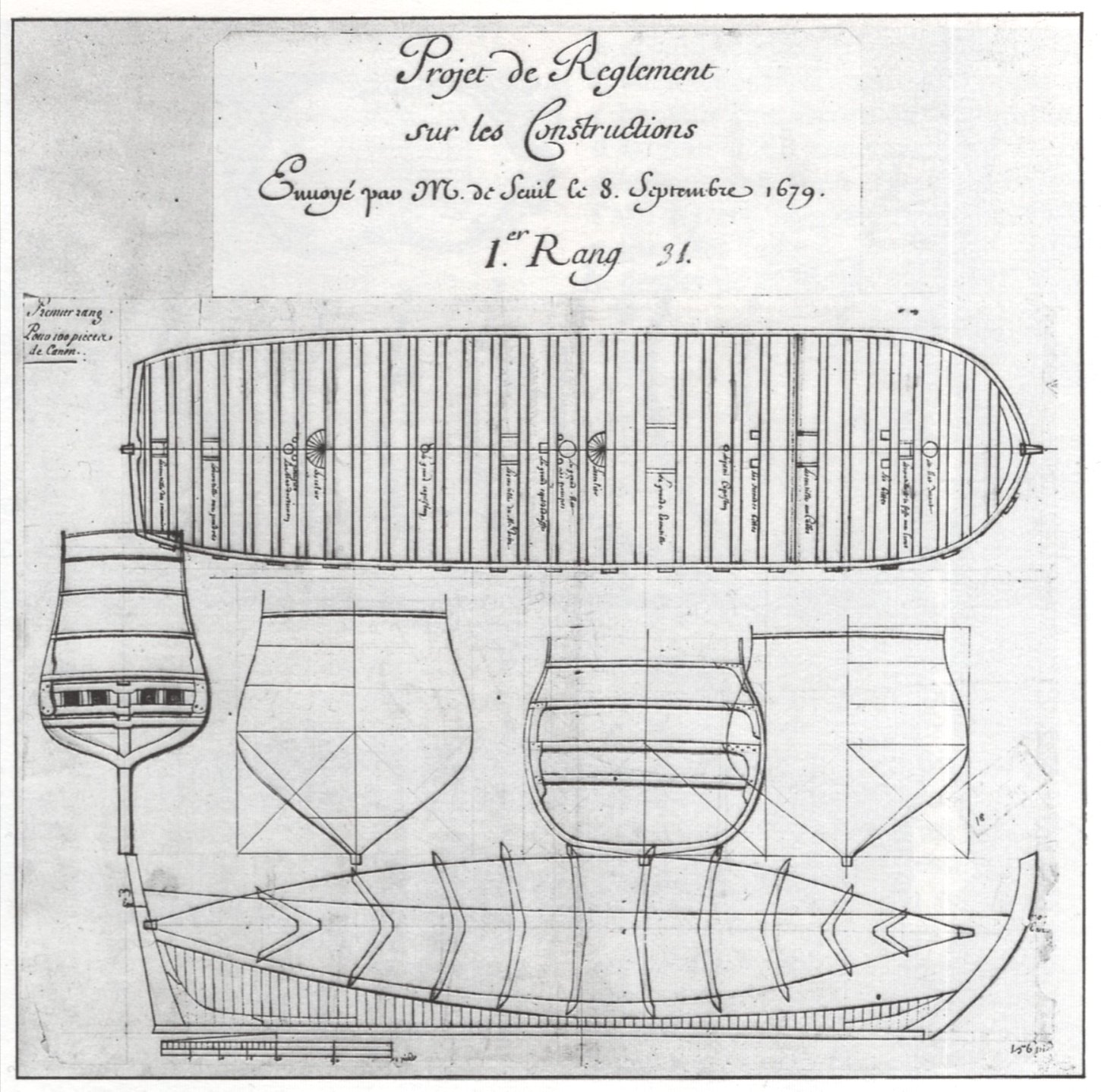
Later design parallels Ships of similar design concept to Mary Rose 1511, from different periods and different regions of northern Europe, have already been mentioned earlier in this thread. Below are a handful of such quite numerous, specific examples, ready at the same time to be shown graphically. Among the cases studied in detail so far, mention should be made of the design of the French heavy frigate of 1686 by Pierre Chaillé (relevant presentation to be found in another forum), and the design of the French light frigate l'Aurore of 1697 by Philippe Cochois (awaiting a separate detailed presentation). Here a reconstruction of the body plan of the latter frigate superimposed on her original period plan. Among the fundamental features, decisively determining the similarity of the methods employed, attention should be drawn first and foremost to the order in which the contours of the conceptual frames were formed, as well as the specific geometrical procedures used for this purpose. Identical as in the Mary Rose case, the bottom (green) was formed first, followed by the lower breadth sweeps (blue), and only in the last step were the two sets joined by reconciling sweeps (red), tangentially at both ends. Among other things, it is still worth pointing out here not only the very fact of the use of quarter frames, but also the same specificity of their use as in the case of Mary Rose. And the draught of l'Aurore of 1697 in its entirety, including the body plan shown above (French archives): Regarding the fundamental importance, in conceptual terms, of the hull bottom, which is in fact the design basis of ships built in the Northern tradition (in the literal sense, as opposed to the Mediterranean tradition), and the specific use of quarter frames, this is particularly very well illustrated on the surviving design proposals of French capital warships of late 17th century. Below is a drawing of one such design for a first rate ship by Laurent and Étienne Hubacs from 1679 (French archives), and among the not very numerous design elements (but already unambiguous for obtaining the specific form of the hulls), there are in particular the two design elements mentioned earlier (that is, the bottom featuring its curves and both quarter frames). Notable are the much fuller shapes at the midship than those of the Mary Rose (providing in themselves better lateral stability and, of course, carrying capacity), required for a heavily armed vessel. In passing, only one of the two double master frames is drawn on the plan (the aft one is omitted), presumably because of the quasi-identity of this pair. In fact, it can be said that the entire description of the Mary Rose's design concept so far, even including the comments on the specifics of the shapes and the resulting properties of ships, is also relevant to the above examples (which, of course, no longer applies to their proportions, individually selected for the intended, specific application of these vessels). Also, by the way, it is worth appreciating the overall flexibility of the Northern method, allowing a wide range of shapes to be obtained according to needs and requirements, which is probably why, among other things, it has been widely used for such a long period of time. It is possible to point to more similar period sources, written and iconographic, as well as providing more detailed explanations, but I guess everything should have its limits 😊. Nevertheless, leaving aside the almost unexplored archaeological finds from this conceptual angle, it is probably appropriate to point out, perhaps more as a curiosity, yet attractively much closer chronologically to Mary Rose 1511, the case of an intriguing votive model of a galleon, dated to the late 16th and early 17th centuries, now in the collection of the Historical Maritime Museum in Stockholm (Votive ship -Sjöhistoriska museet / DigitaltMuseum). Although an attempt at a conceptual reconstruction of this model has already been made by Peter Kirsch and presented in his excellent publication The Galleon. The Great Ships of the Armada Era, published in 1990, but now, in the light of recent investigations in this area, it may raise objections due to it being essentially based on English shipbuilding manuscripts of the first half of the 17th century, closer to Mediterranean traditions, which in effect generated the trapezoidal hull cross-sections in this reconstruction, characteristic precisely of Mediterranean three-arc master frame designs. However, the cross-sections reconstructed in this way are quite noticeably different from the round cross-sections featured by the original model, as can be judged from the following comparison graphic (as an aside, an identical treatment was attempted in the inevitably unfinished attempt at a conceptual reconstruction of the Mary Rose herself, published in one of the chapters of the ship's monograph). Naturally, it has to be taken into account that the hull of the original model is probably somewhat flattened in the manner typical of votive models; nevertheless, the specificity of the shapes in this model is quite telling and begs for the use of Northern, single-arc master frame design (plus reconciling sweep), precisely as in Mary Rose 1511. Admittedly, on the one hand, such a choice might be made easier by more confidently establishing the provenance of the model itself (essentially unknown) on criteria other than the shape of the hull, yet, conversely, this very feature might help to establish the place of origin and time of its creation. As for the plausibility of the very specificity of the shapes of the Stockholm galleon model itself, at least in the light of the corresponding cross-section shapes of the wreck of the Swedish naval ship Bodekull, in service between 1661 and 1678, it does not raise any reasonable doubts, as can be compared with the sample graphic below. It is worth noting here that Bodekull was built in the period when English design methods were only just beginning to be implemented in Sweden. The 3D scan of the wreck is made available on the Sketchfab website by Swedish Historical Maritime Museum (3D models by SWEDISH NATIONAL MARITIME AND TRANSPORT MUSEUMS (@maritima) - Sketchfab), and more about this wreck and the ship itself may be found in a paper by Niklas Eriksson, A New View of the ‘Edesö Wreck’: identifying the Swedish naval vessel Bodekull, built 1659–1661 and sunk 1678 from written sources, 2018, and attached below. Eriksson Niklas - A New View of the ‘Edesö Wreck’ – identifying the Swedish naval vessel Bodekull, built 1659–1661 and sunk 1678 from written sources - IJNA 2018-47-2.pdf
.thumb.jpg.ef703960e9791ecaddec13cd280091b0.jpg)
-
Mary Rose 1511 — the epitome of the Northern tradition
Waldemar replied to Waldemar's topic in Nautical/Naval History
Thanks a lot, Patrick. That's interesting and new information you provide above regarding the unfinished process of clearing the ship. Also, this is probably a good time to say that your adventures or endeavours, especially those concerning the formation of the hull shapes of your impressive Mary Rose model, which you show in your thread, also influenced the very idea of dealing with this case . -
Mary Rose 1511 — the epitome of the Northern tradition
Waldemar replied to Waldemar's topic in Nautical/Naval History
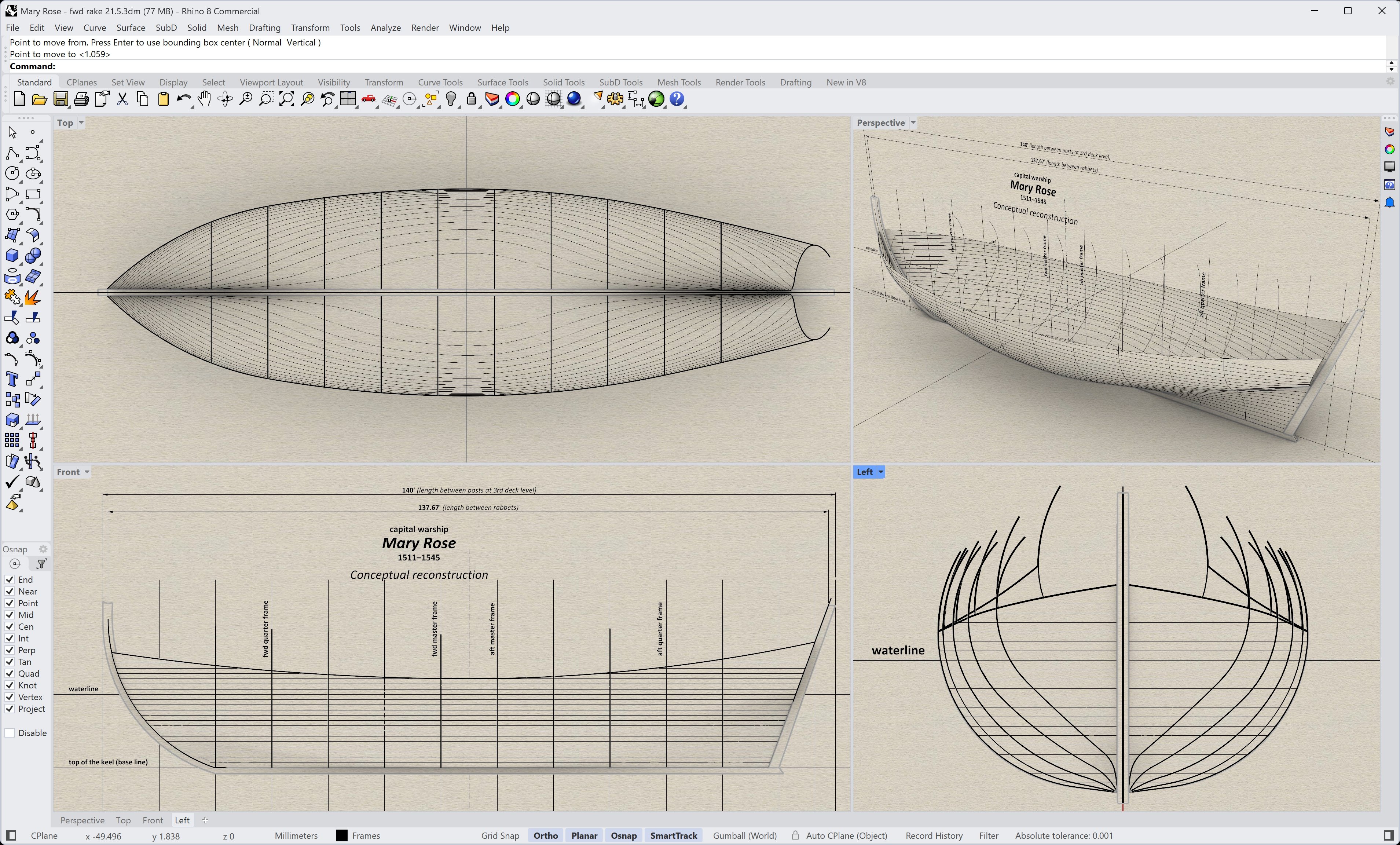
Admittedly, It was still planned to make and present a regular line plan of the underwater part of the hull, possibly for use in model building, for example. Instead, until then, for a demonstration of the final shape of the underwater part of the hull, below are quick renders including waterlines, perhaps best illustrating the nature of the Mary Rose's hull shapes. As a reminder, the waterlines shown here are purely consequential, that is, they took no part in the formation of the shapes (i.e. on the basis of the cross-sections, waterlines and buttocks synchronization, procedure not applicable at the time). These were obtained in their entirety by the found design method shown earlier.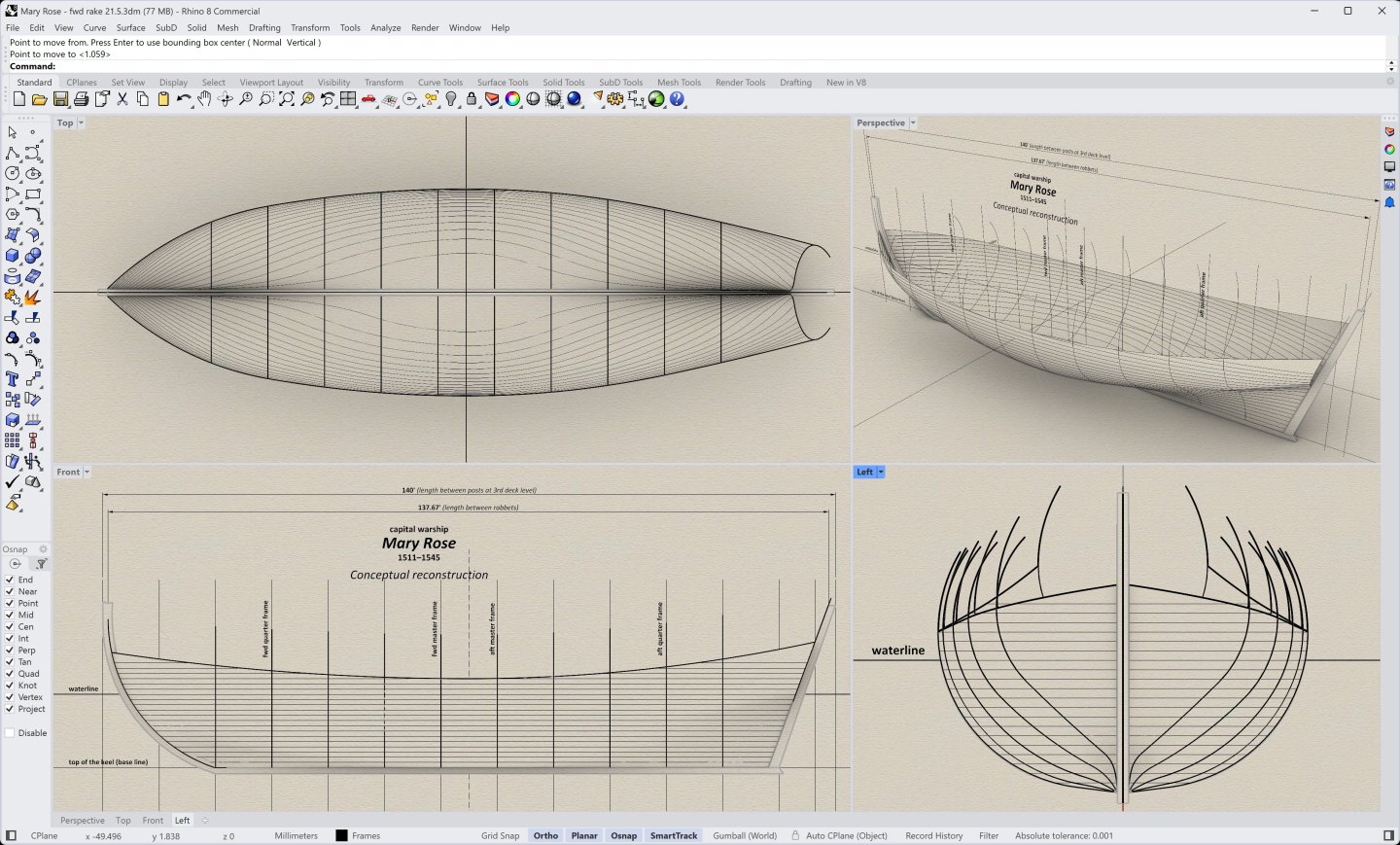
-
Mary Rose 1511 — the epitome of the Northern tradition
Waldemar replied to Waldemar's topic in Nautical/Naval History
Agreed. Overall, the hull shapes may be considered successful indeed, deserving the term ‘the noblest shippe’ — the lines of the hull seem to be sharp enough for the ship to move and keep to the wind well, yet not excessively, which would only make her prone to the pitching effect and to the rapid hogging as well (incidentally, as could be revealed from the wreck's scan, at the time of her demise, some 1.5–2 feet at the midship). Just that circular hull cross-section with the narrow bottom, and the resulting lateral stability problems...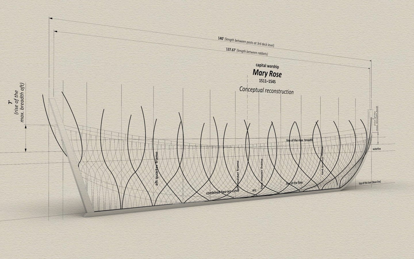
-
Mary Rose 1511 — the epitome of the Northern tradition
Waldemar replied to Waldemar's topic in Nautical/Naval History
Thank you, gentlemen, interesting reading. My personal perception is that the very attempts to resolve quite specific technical issues solely on too high, shall we say, general cultural or humanistic level, which may in fact lead to virtually any conclusion, emphatically confirm the necessity of a relevant and routine study of the wrecks (preferably in the context of other artefacts from the period — iconography, written sources), precisely from the conceptual angle, and not primarily from the carpentry angle, to which it has so far usually been confined. Otherwise it will be a kind of chasing one's own tail, which is unlikely to lead to anything authoritative. In fact, it is even worse than that, because a few decades ago such considerations, based mainly on general historical premises and only rather selectively and at the same time overly flexible to sources of a technical nature, led to voluntaristic or even fanciful hypotheses and theories which today do not stand up to confrontation with the results of analyses of a conceptual nature. Nevertheless, now these theories, unfortunately already well established in the popular consciousness, are naturally defended by their authors and proponents, including by attempts to discredit troublesome, later contributions in probably every possible way, and even by attempts at bribery, preferably for the cessation of relevant research in this area altogether (I know what I am writing about ). Let me use an example. It has been hypothesised above that Henry VIII's shipwrights had an incentive to gather ideas widely, due to the ruler's inclinations on the matter. Maybe, but at the same time it is known that shipwrights are probably one of the most conservative professional groups because of the risk of paying too high a price for experiments with unknown consequences. Besides, it is known from sources that they were able indeed to refuse their rulers, such as the above-mentioned refusal to overhaul the Genoese carracks, or the refusal to rearrange the bow of one of the large ships (Great Harry or Mary Rose) to install additional heavy guns there. A rather apt summary of this issue is perhaps Duhamel du Monceau's comment, which makes it clear that the shipwrights stuck rather tightly to one design which they considered good enough, implementing it repeatedly in subsequent builds, and for this very reason encourages them to be more adventurous in their experimentation. With greater effect? Personally, I doubt it, in keeping with the paremia — tempora mutantur, sed homines manent eodem. -
Mary Rose 1511 — the epitome of the Northern tradition
Waldemar replied to Waldemar's topic in Nautical/Naval History
Personally, I associate the implementation of the three-arc master frame design in England with Mathew Baker's educational trip to Italy in the early 3rd decade of the 16th century, precisely to learn Venetian ship design techniques. However, your suggestion that Spanish involvement during Queen Mary's reign may have influenced this transformation also seems plausible, given that the Basque whaler San Juan, dating from around 1550, also exhibits just such three-arc master frame configuration. And, after all, the two supposed causes or stimuli need not be at all mutually exclusive, quite the contrary... -
Mary Rose 1511 — the epitome of the Northern tradition
Waldemar replied to Waldemar's topic in Nautical/Naval History
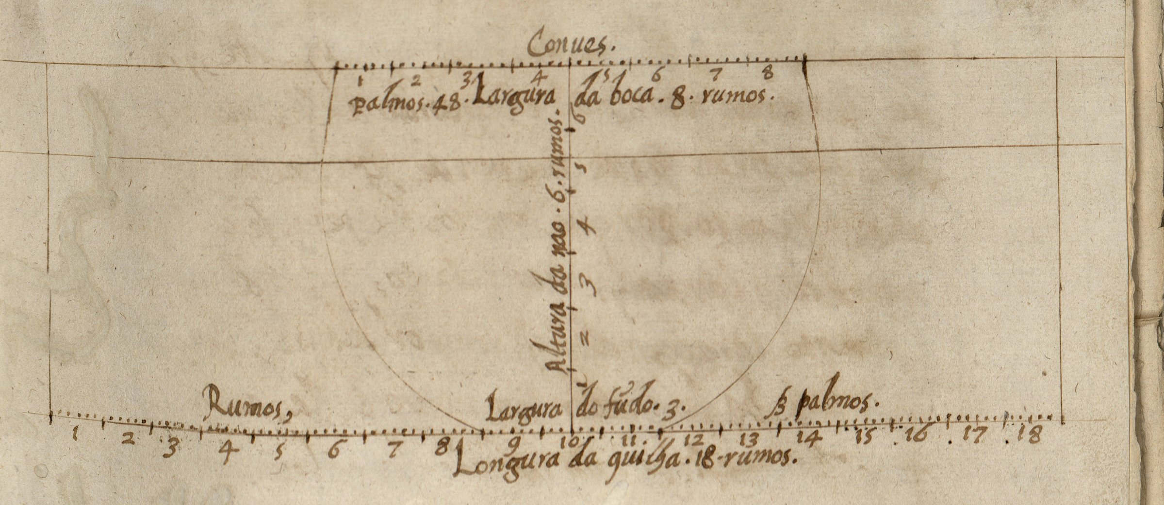
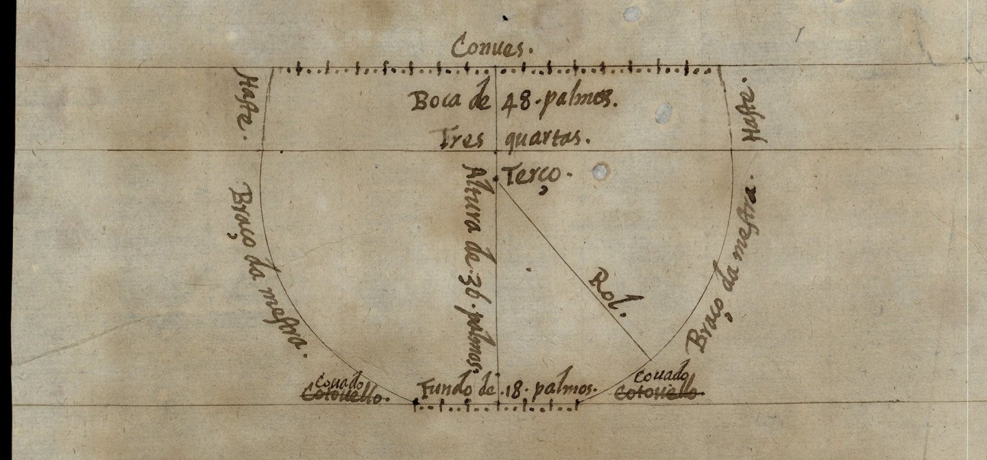
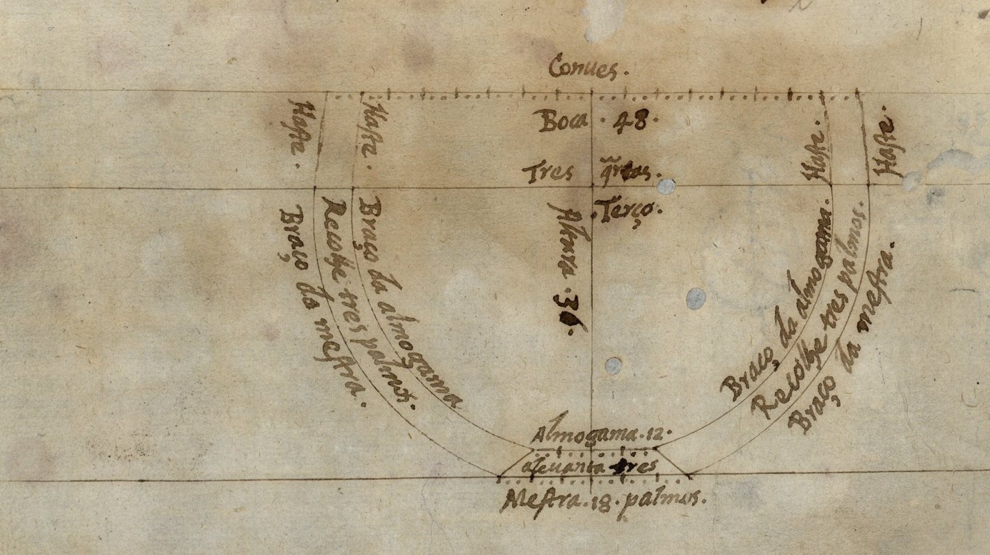
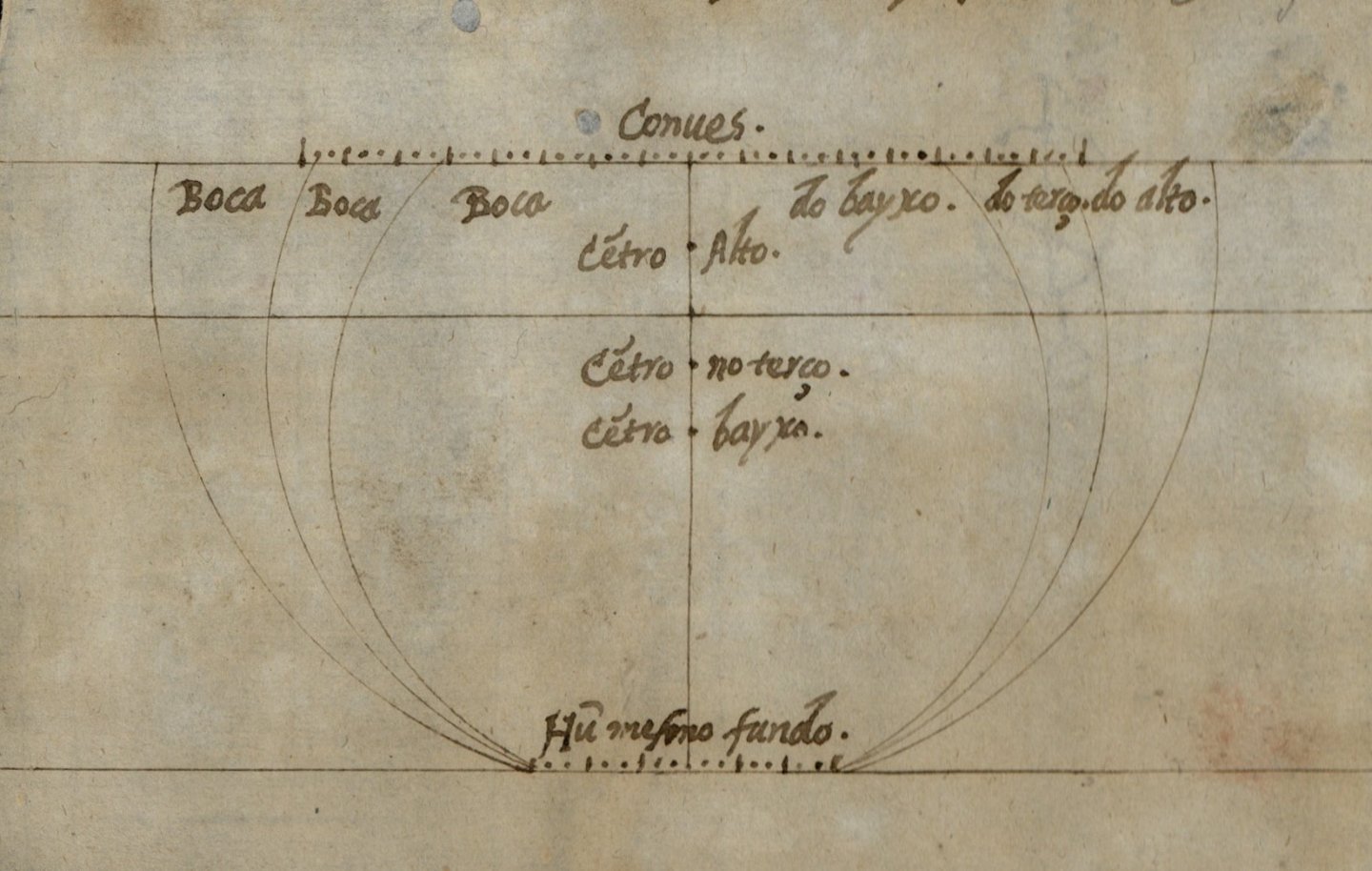
To be honest, I am not sure that the widespread dissemination of ideas and methods in this later period does not already make such very late Portuguese examples not very authoritative, however, when one looks, for example, at the designs of the master frame by Portuguese Fernando Oliveira from around 1570–1580, such a view already takes on the characteristics of plausibility. They are round, and have a quite narrow bottom. As do most of the designs for seagoing ships in Livro de Traças de Carpintaria, 1616 by Manoel Fernandes, a Portuguese too, which also demonstrate essentially quite circular sections and narrow bottoms. Below are master frame designs from the manuscript O livro da fábrica das naus by Fernando Oliveira, all sporting a single-arc contour and relatively narrow bottom.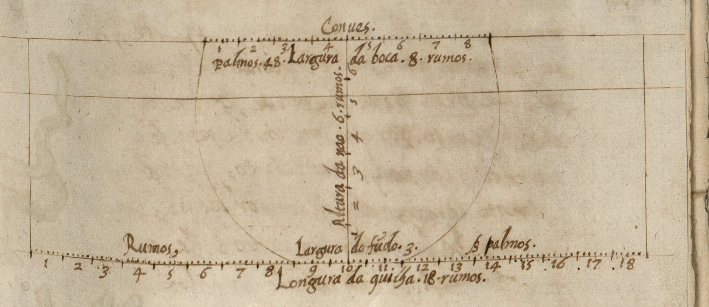
-
Mary Rose 1511 — the epitome of the Northern tradition
Waldemar replied to Waldemar's topic in Nautical/Naval History
Yeah, as we've discussed before, those round hull cross-sections ‘screamed’ to be corrected as soon as heavy artillery started to be installed on the ships. However, the Mary Rose was not one of them neither. It even occurred to me that until the adoption of the Mediterranean three-arc master frame design, the ships were built as before, i.e. sporting single-arc master frame, and immediately “upgraded” to the new standards and needs by those side “blisters”. Perhaps they simply could not design any differently than before. And this is why there was such widespread and rapid adoption of this Mediterranean specificity in Mathew Baker's time. -
Mary Rose 1511 — the epitome of the Northern tradition
Waldemar replied to Waldemar's topic in Nautical/Naval History
I will also take this opportunity to attach the paper by R. C. Anderson dated 1960 and published in The Mariner's Mirror, which indeed cites an extant document of this nature and from this very period. It concerns the ship Mary of the early 16th century. The set of figures is admittedly somewhat different from the list above, and the values given are absolute (as opposed to relative proportions), nevertheless a number of the items recorded relate specifically to hull shapes and not just the size of the ship and its components. Anderson R. C. - The Mary Gonson - Mariner's Mirror 46, 1960-3.pdf


.jpg.4f95544e2782fee440c4e51e7de3f1c0.jpg)