HOLIDAY DONATION DRIVE - SUPPORT MSW - DO YOUR PART TO KEEP THIS GREAT FORUM GOING! (Only 20 donations so far - C'mon guys!)
×
Rock_From_Korea
-
Posts
310 -
Joined
-
Last visited
Content Type
Profiles
Forums
Gallery
Events
Everything posted by Rock_From_Korea
-
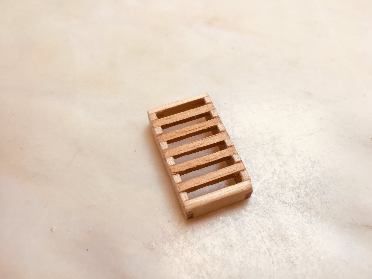
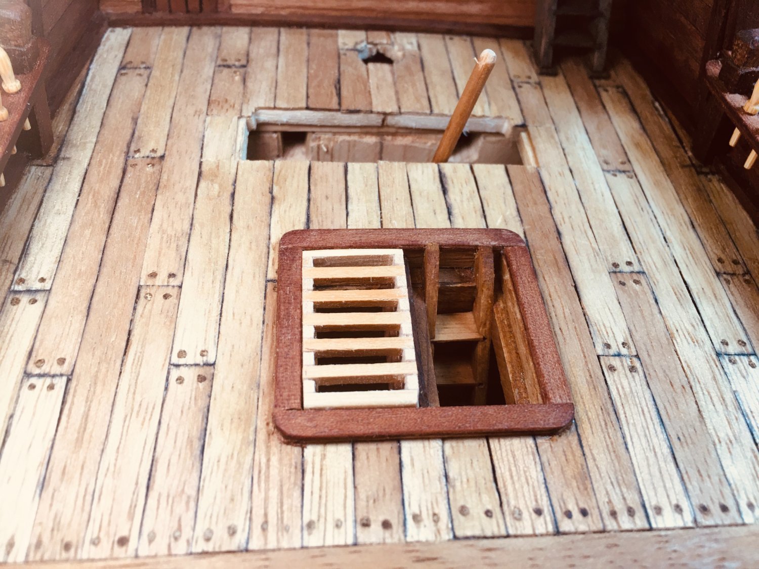
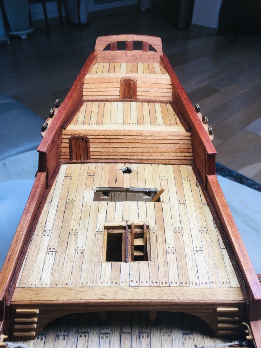
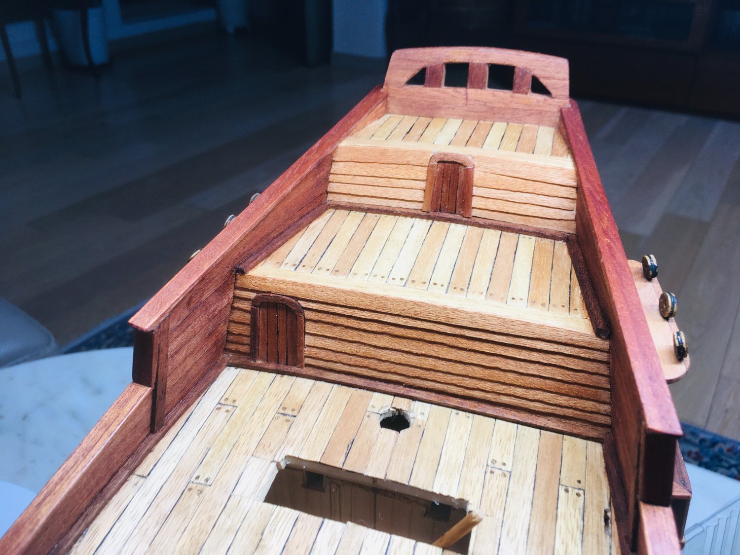
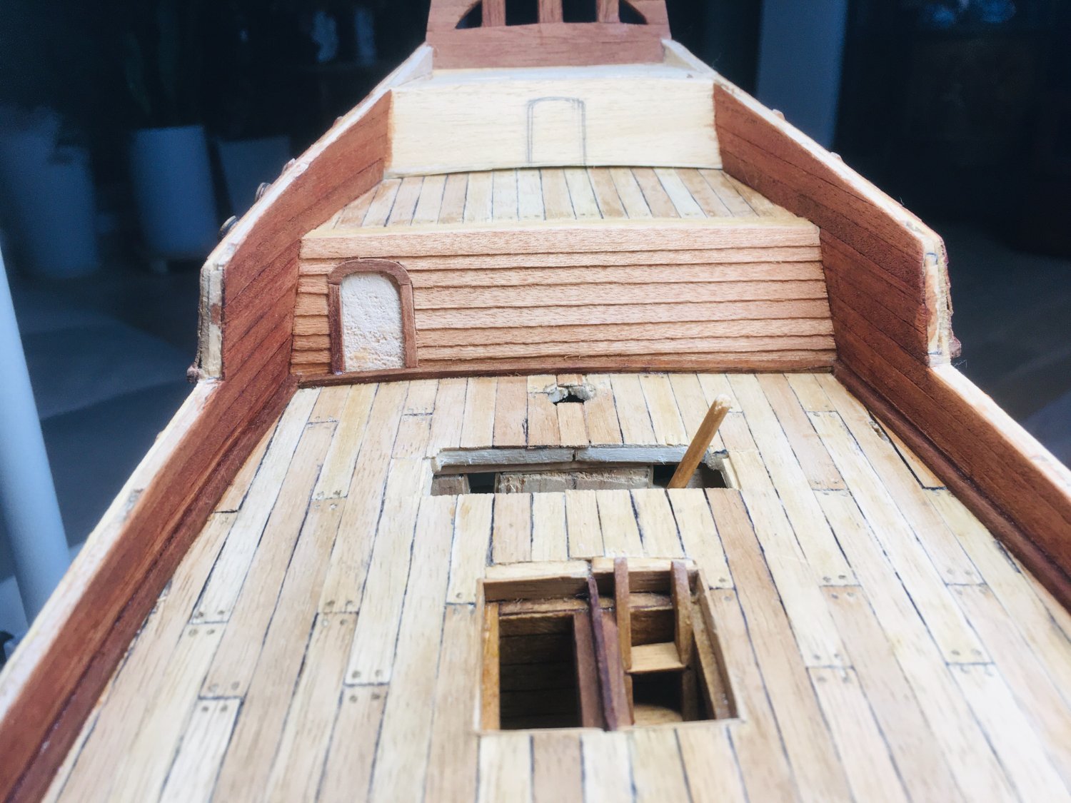
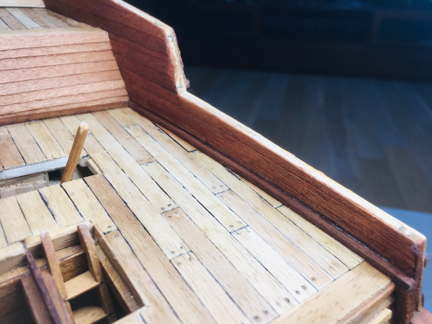
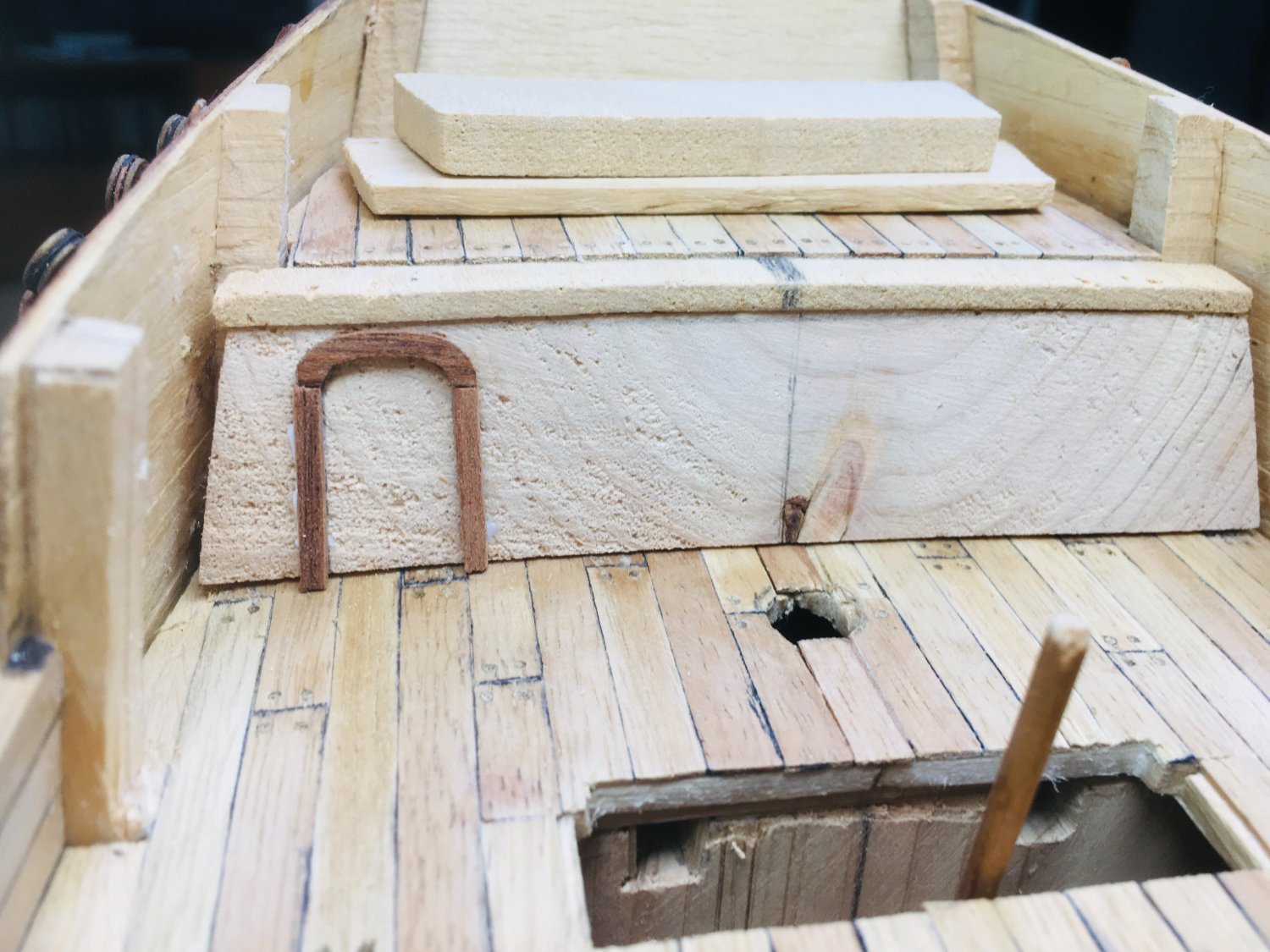
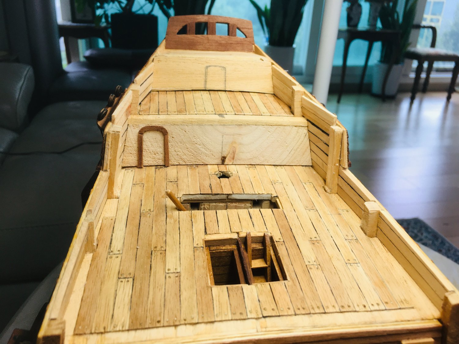
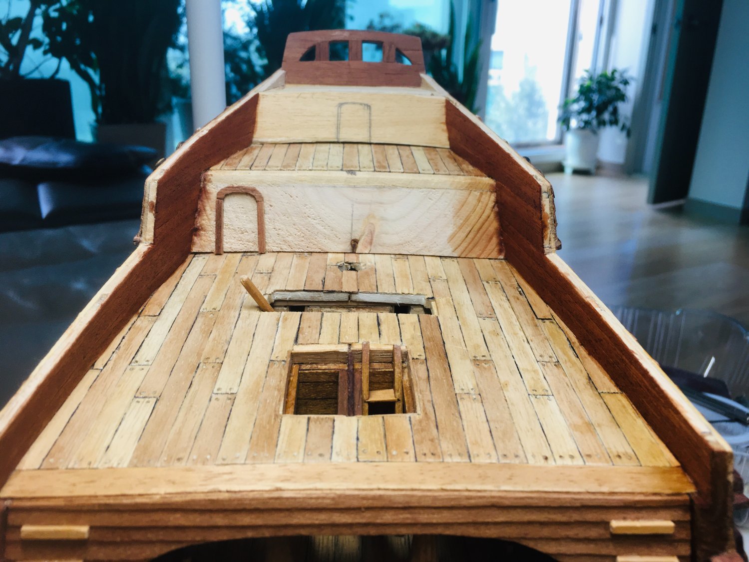
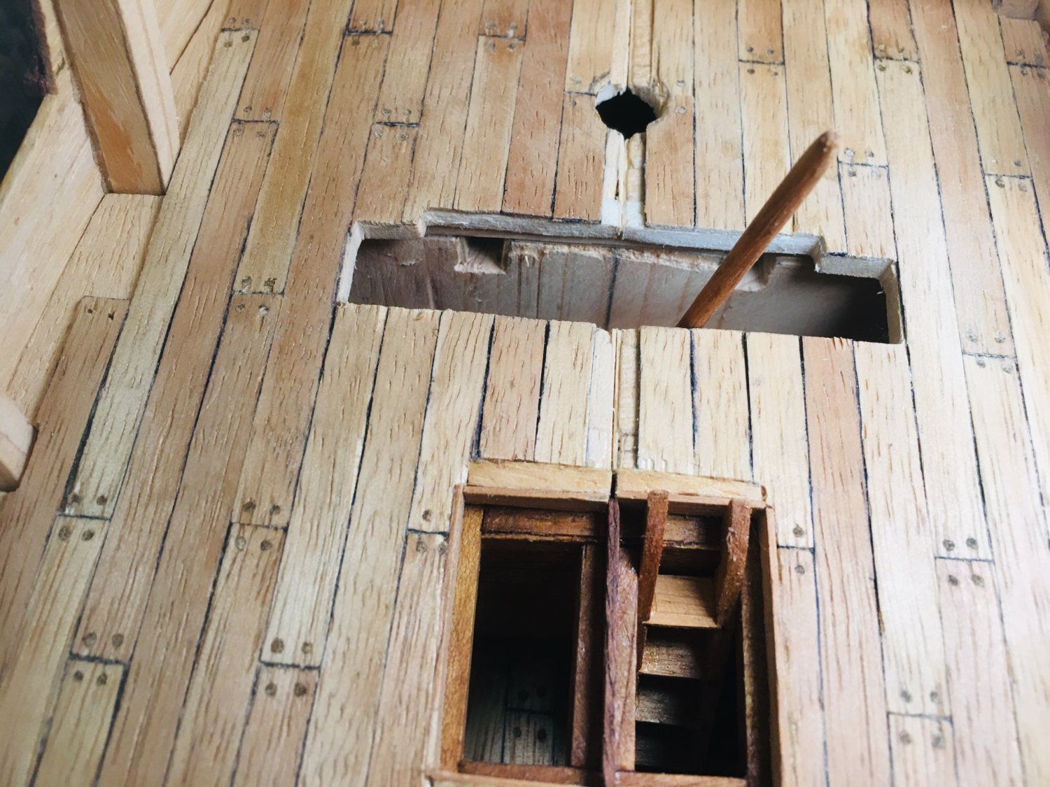
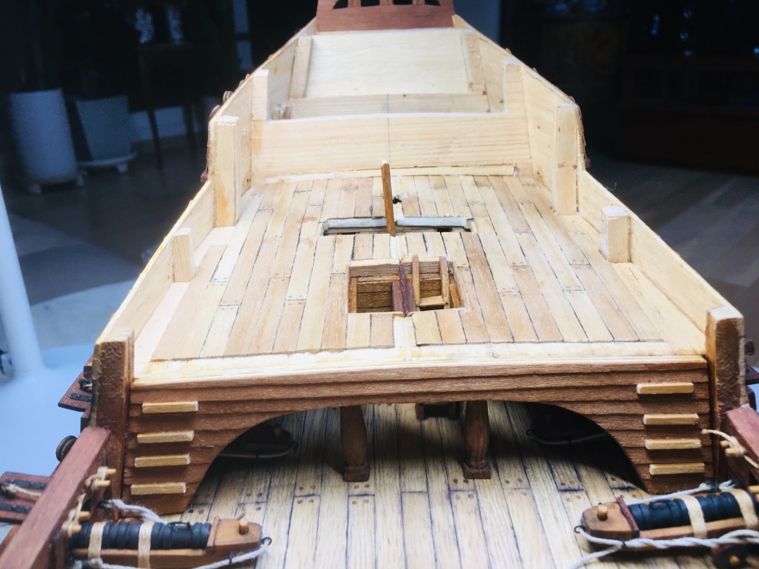
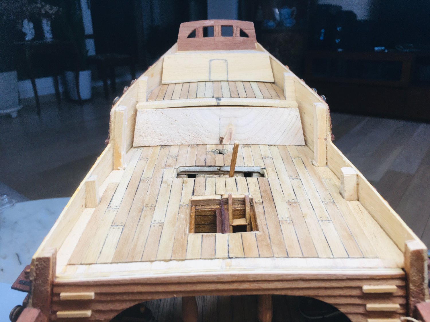
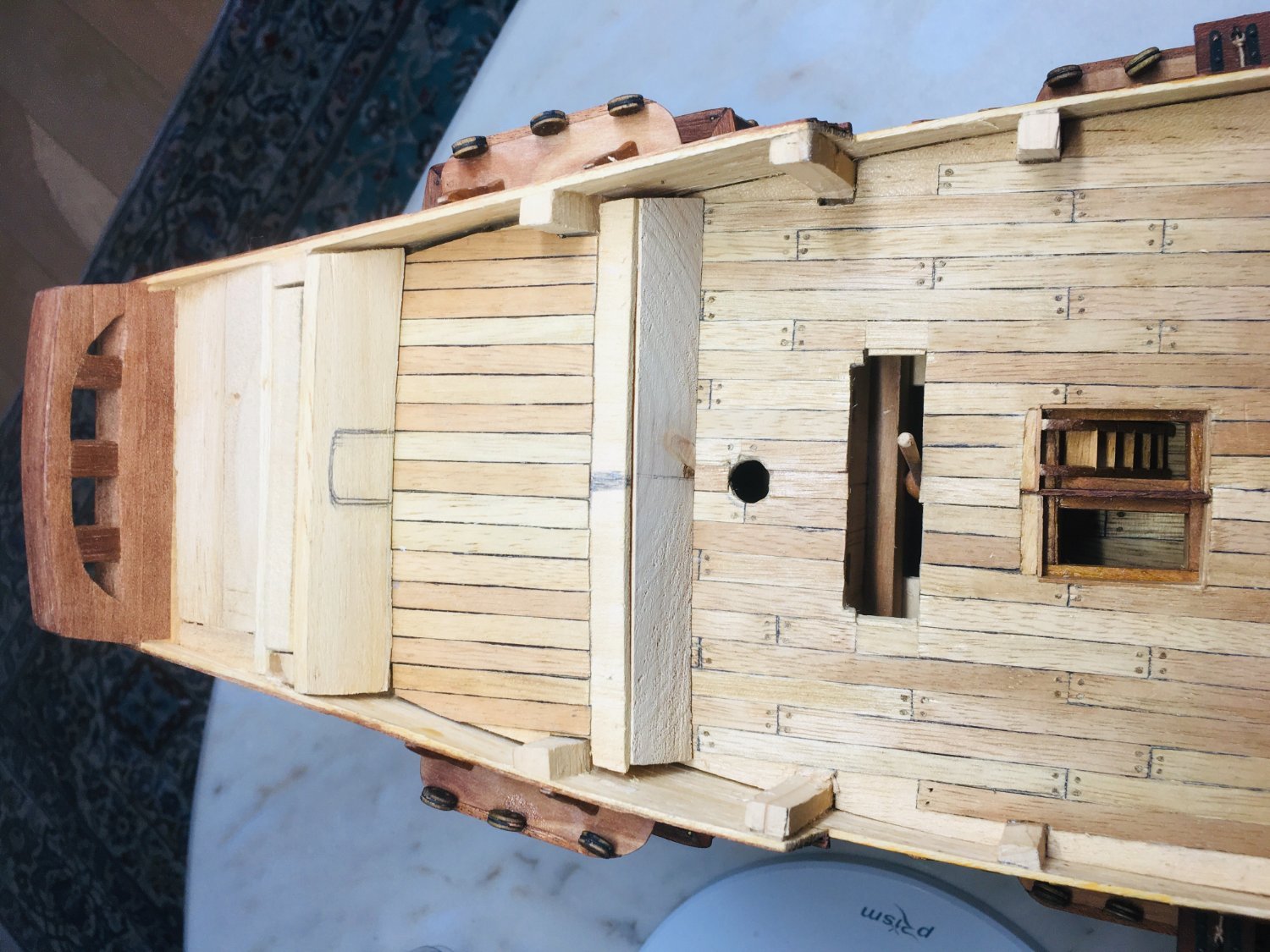
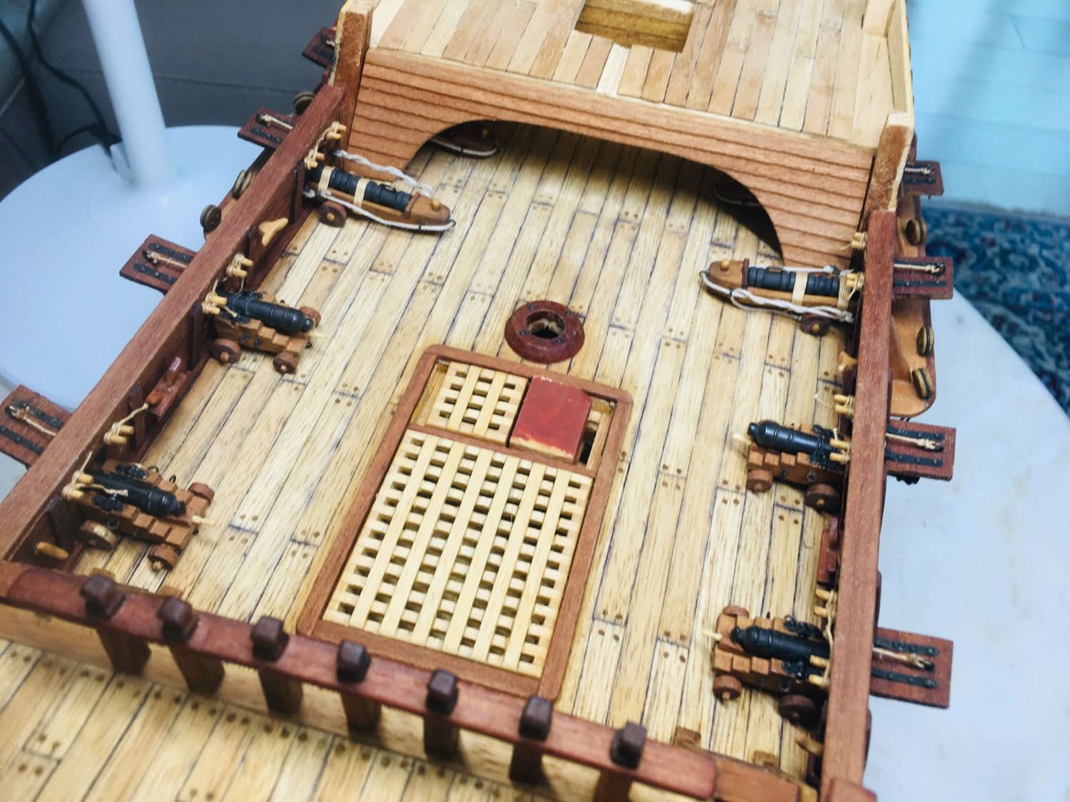
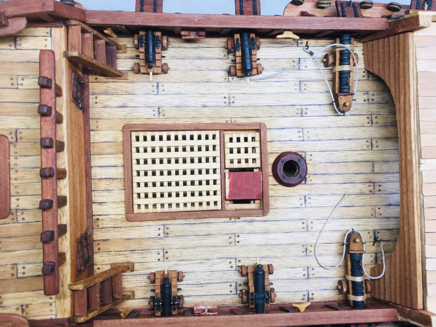
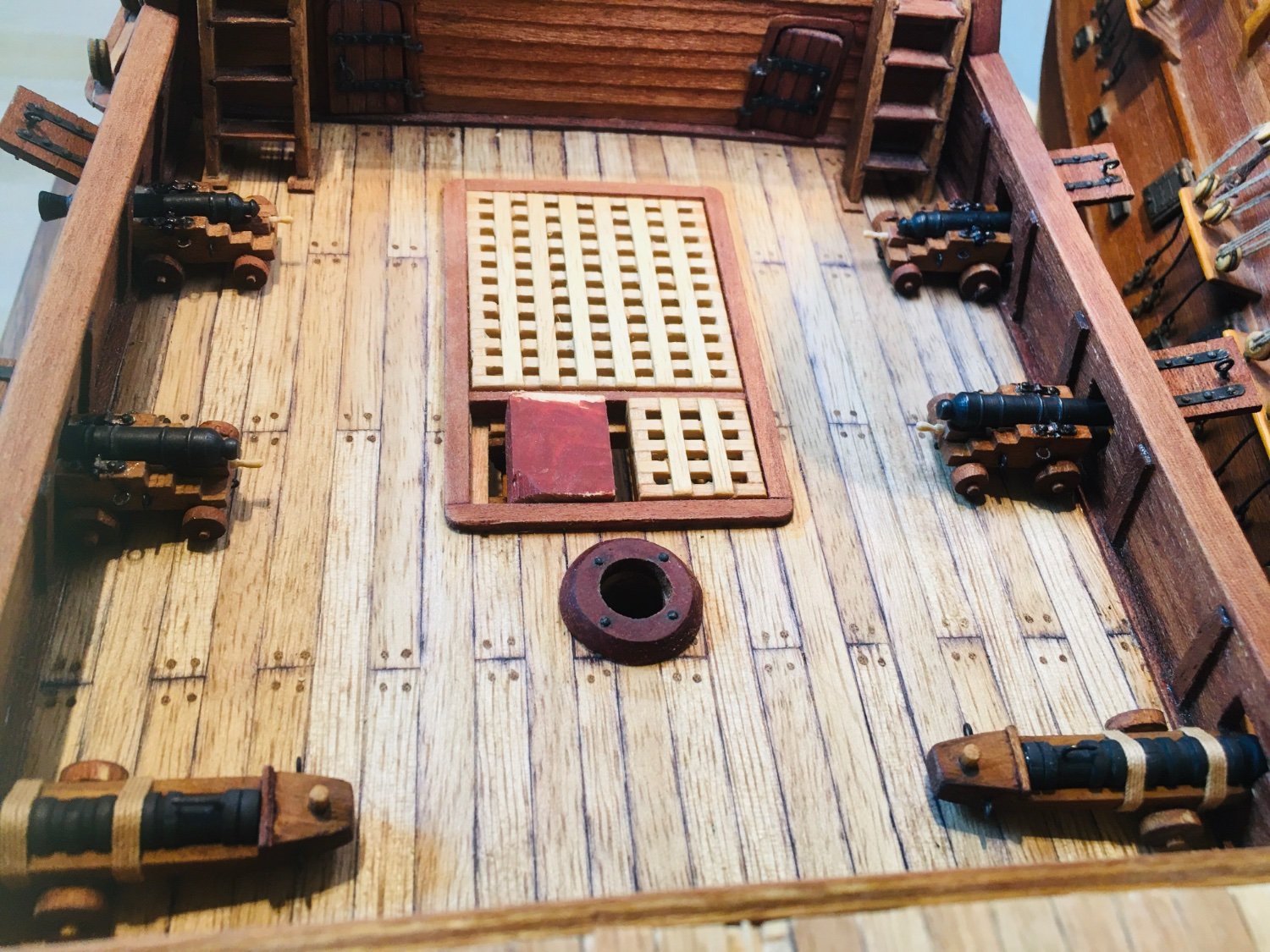
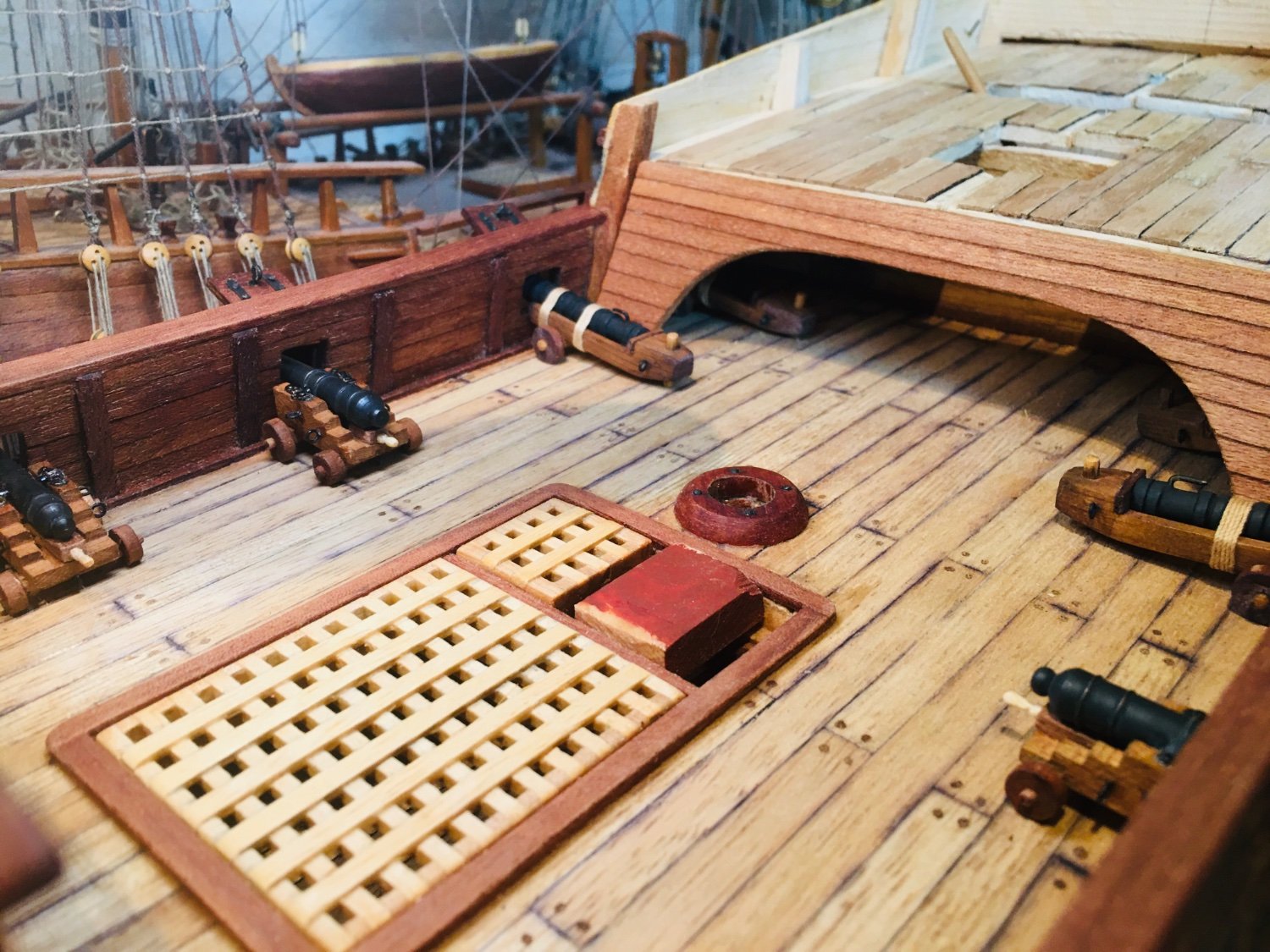
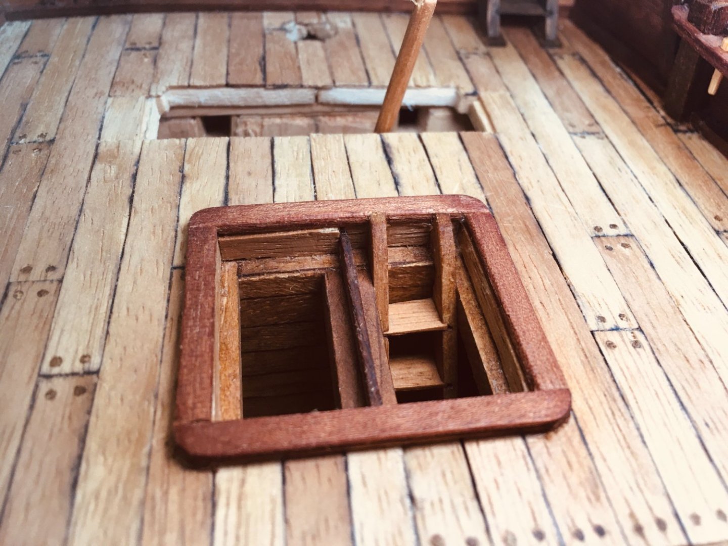
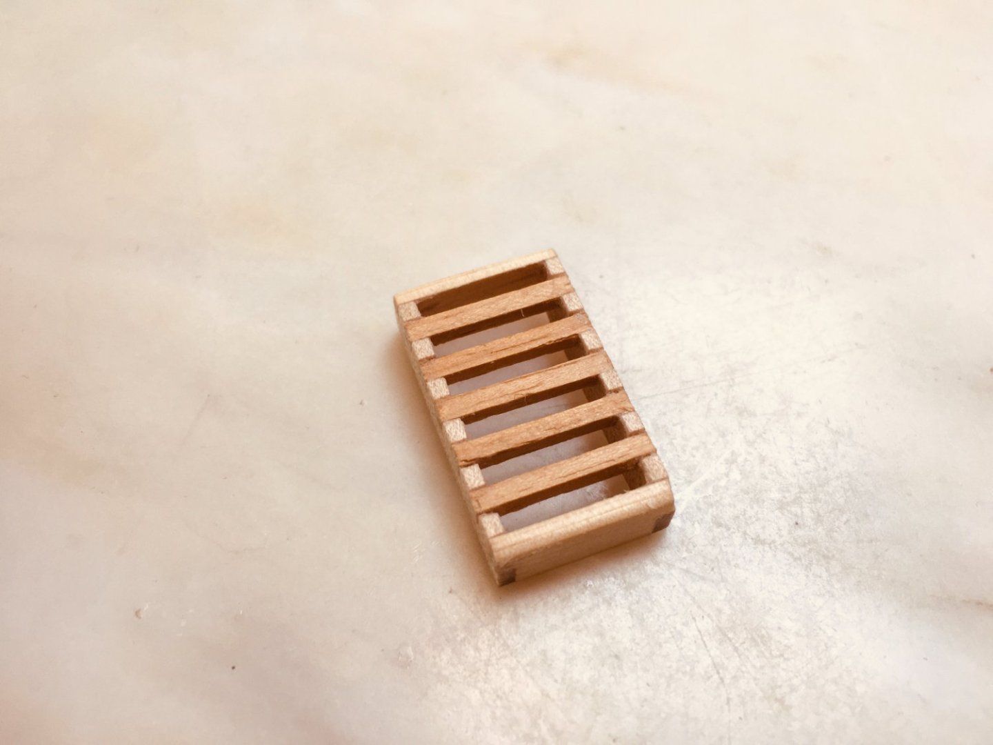
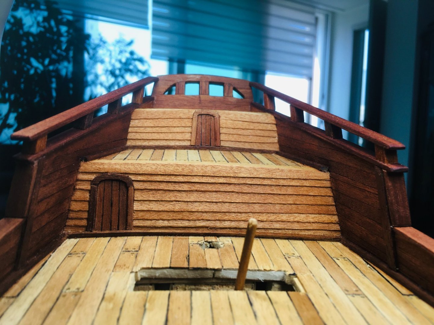
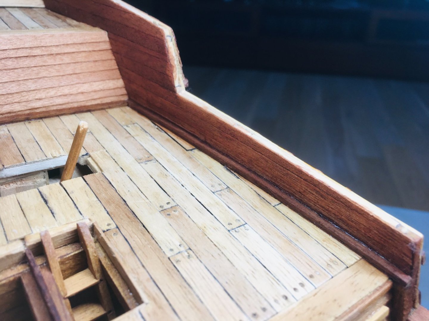
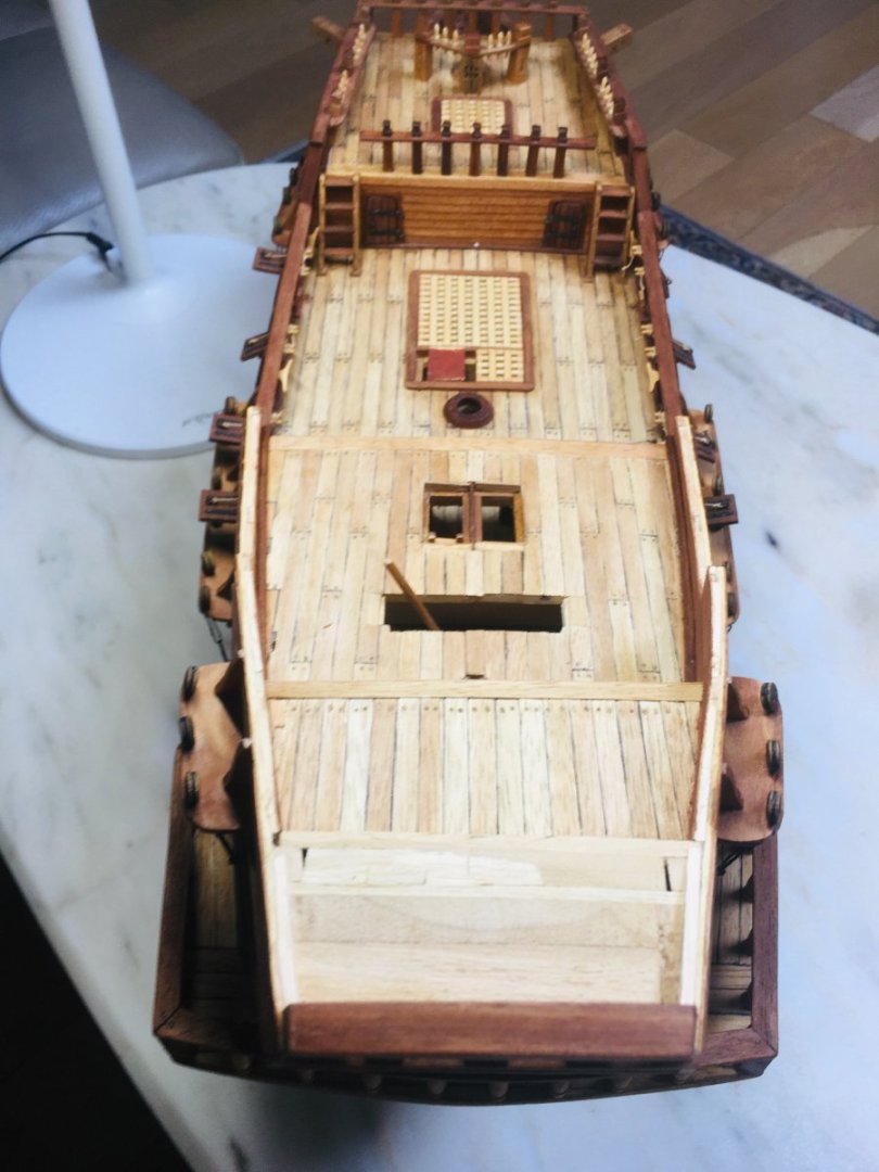
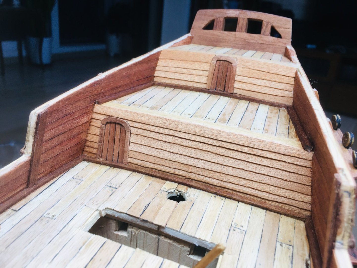
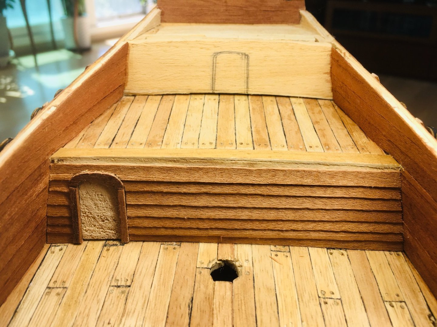
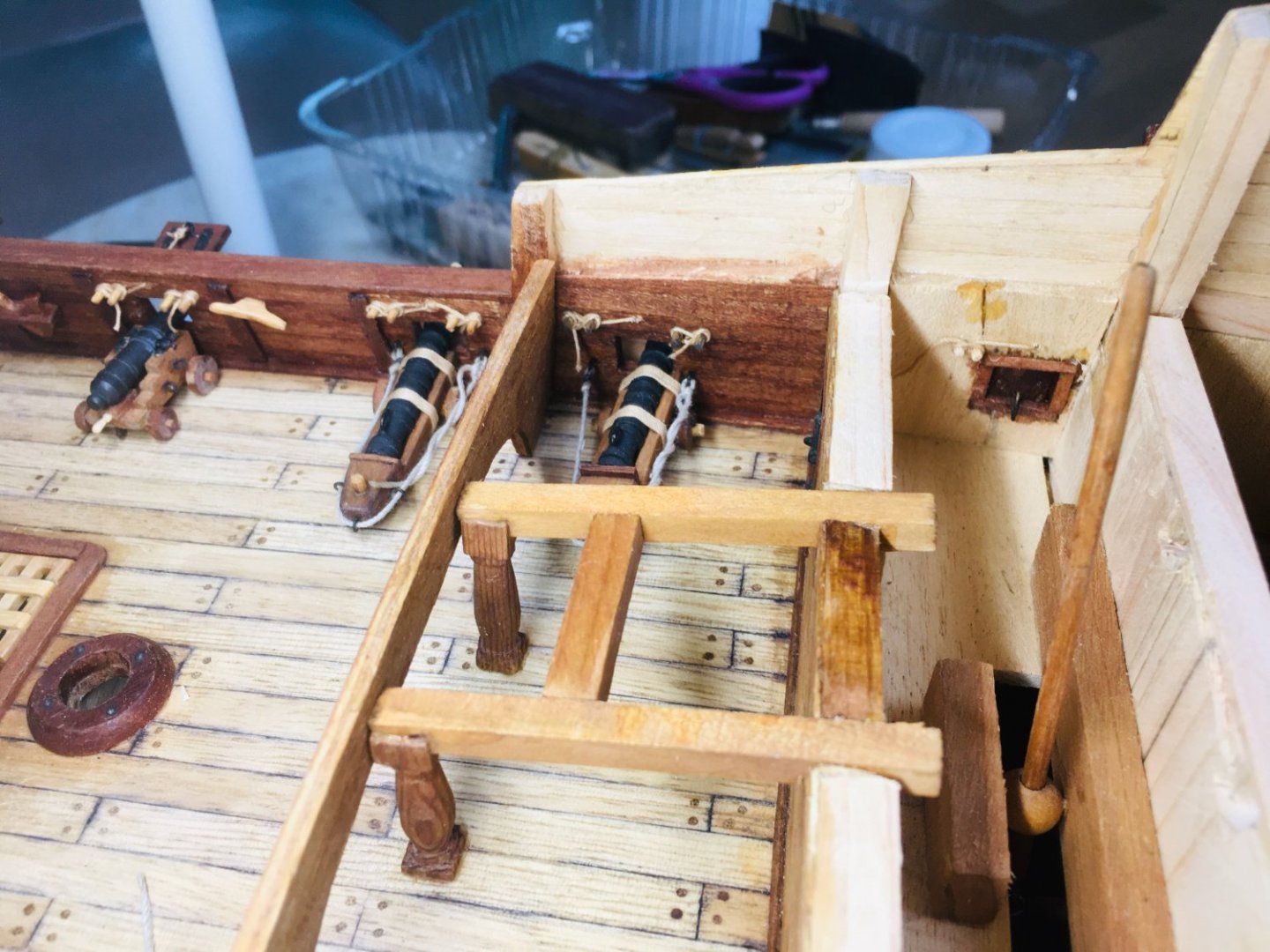
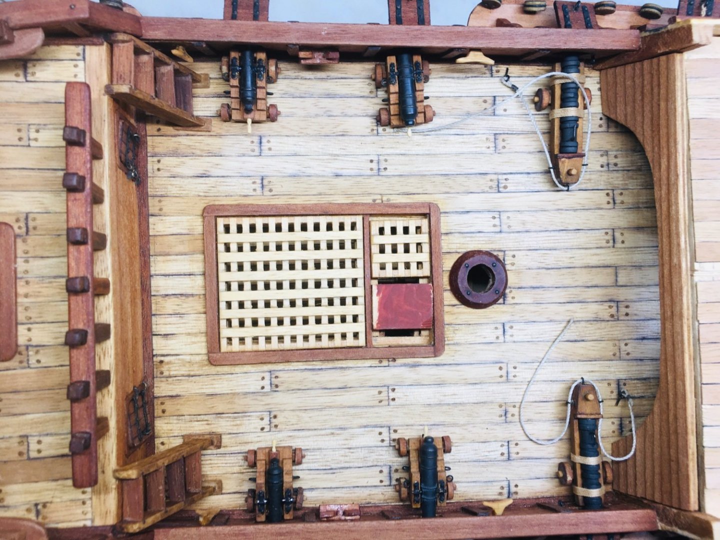
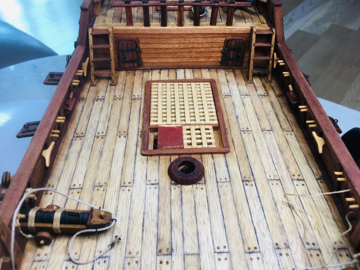
 Hello All~ It's been a long time since my last update! I had to take time off from the shipyard due to minor injury on my left hand. Now fully functional again~ So, I have restarted on where I left off. Continuing on the quaterdeck grating and whipstaff house. First, below are some pictures on the quarterdeck grating.
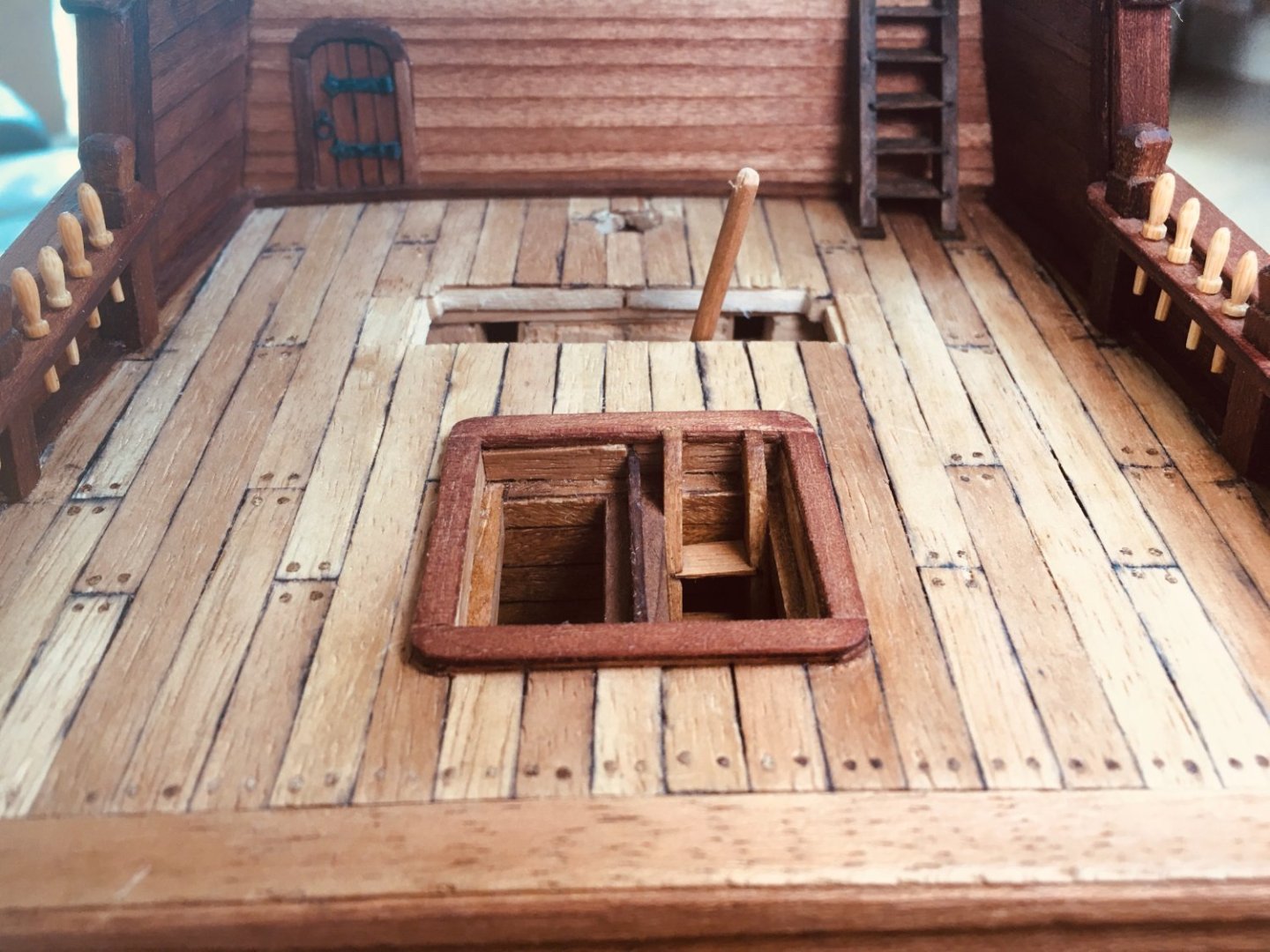


-
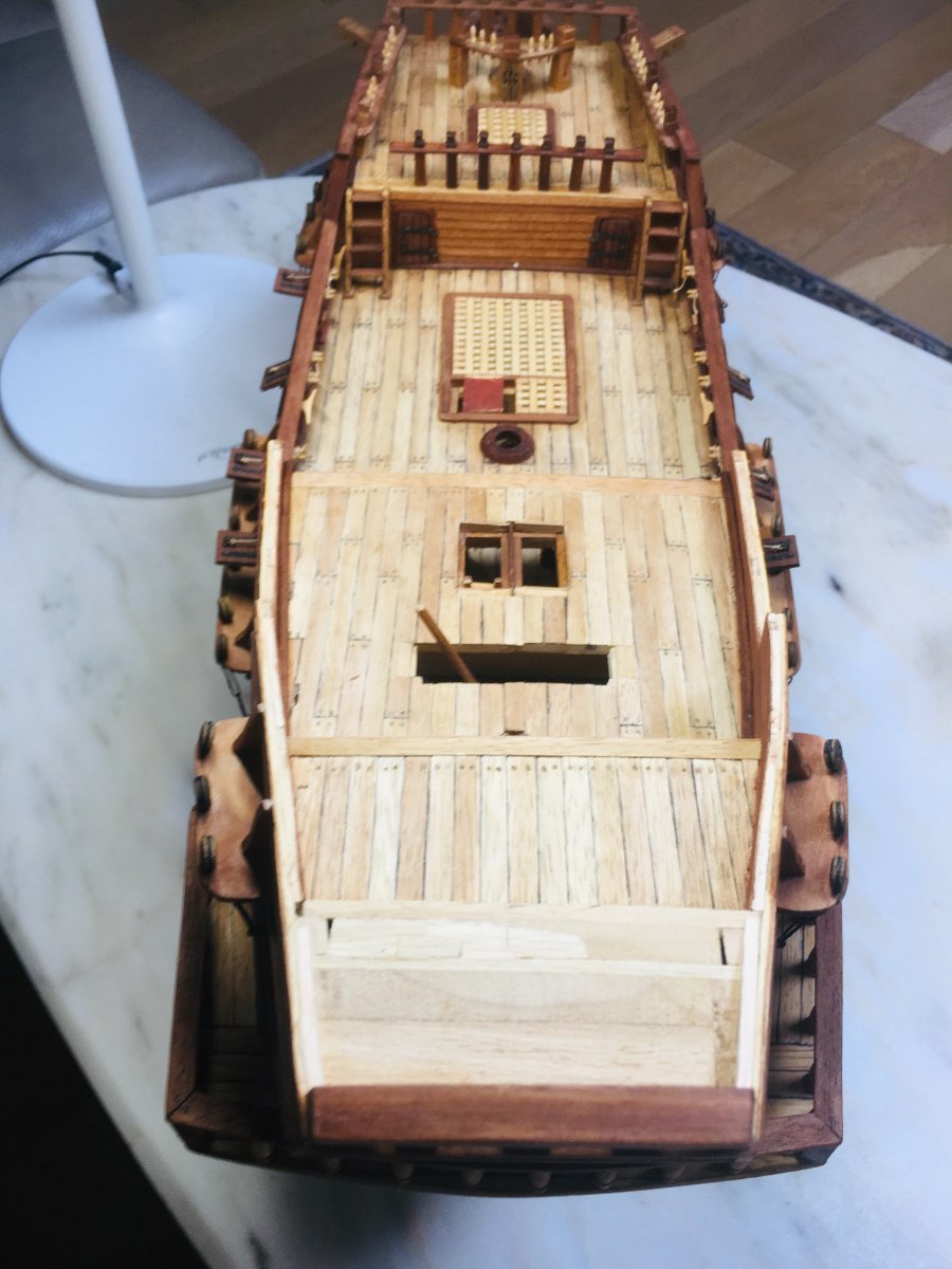
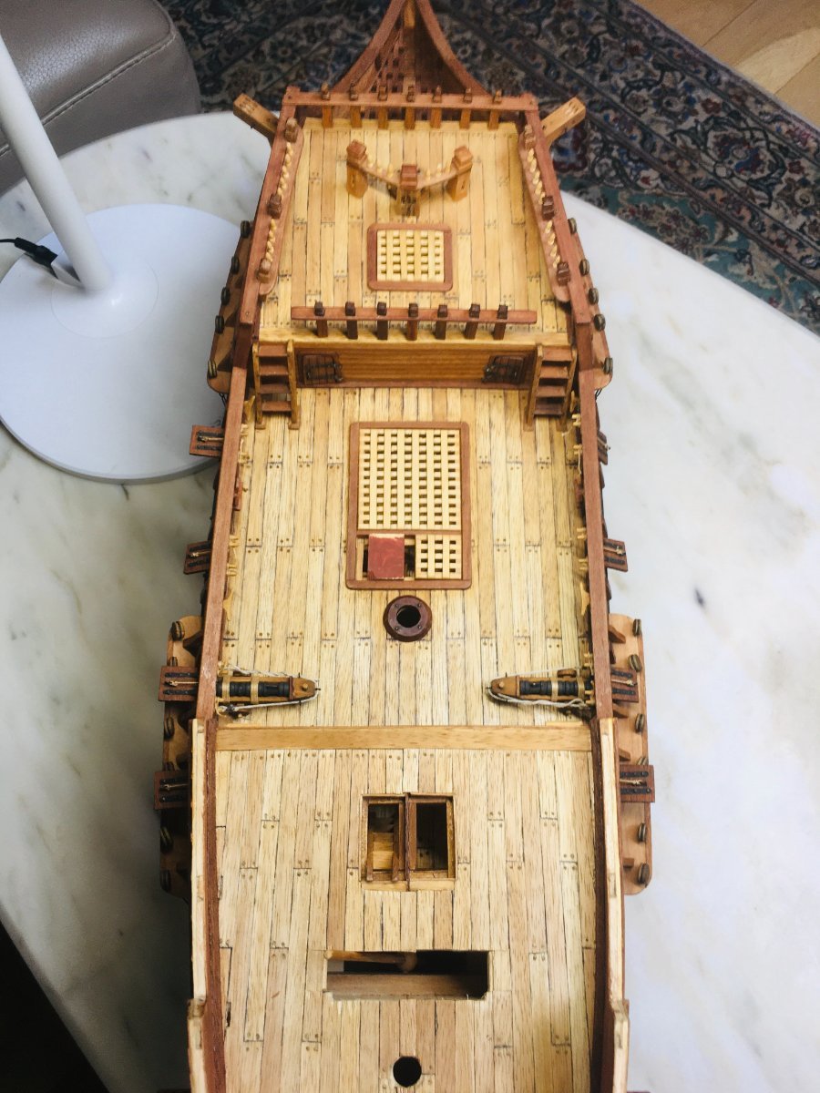
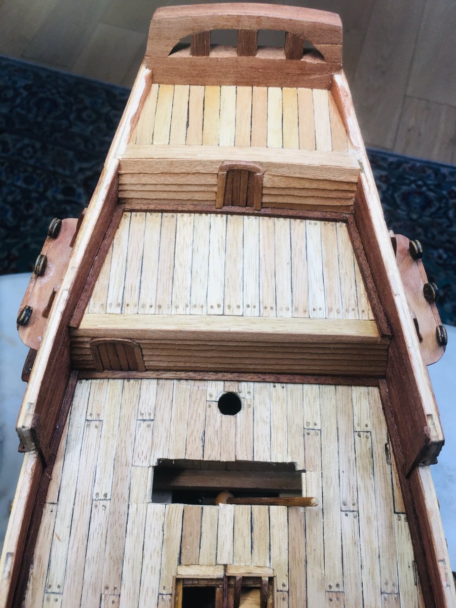
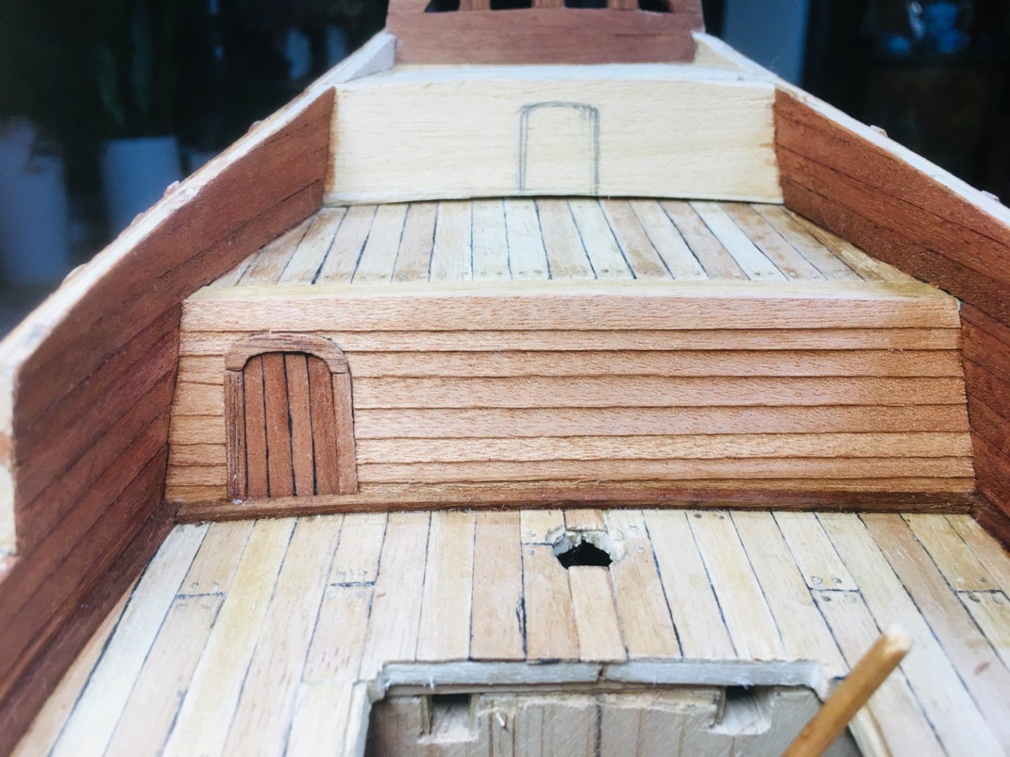
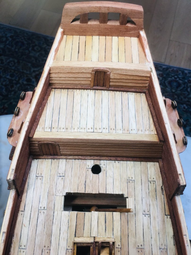
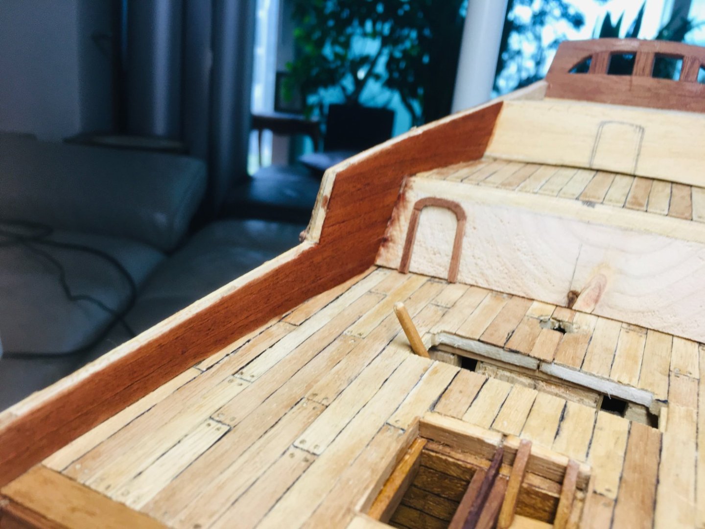
More progress pictures...


-
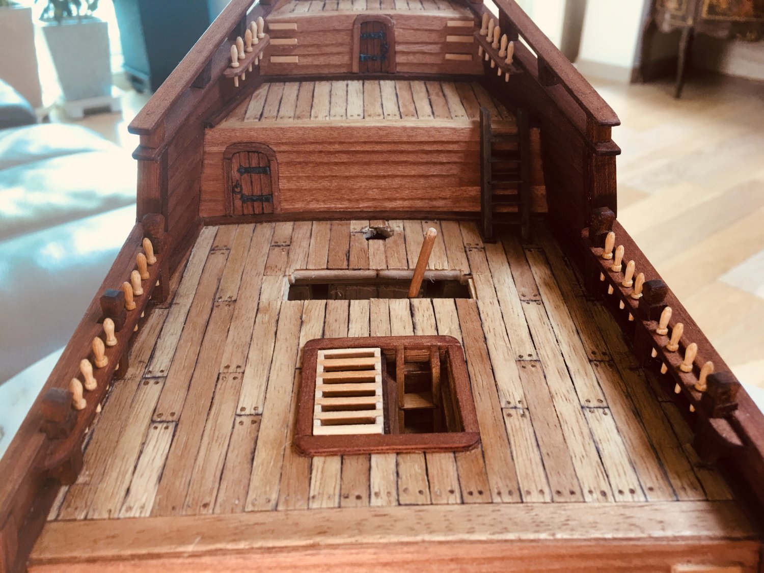
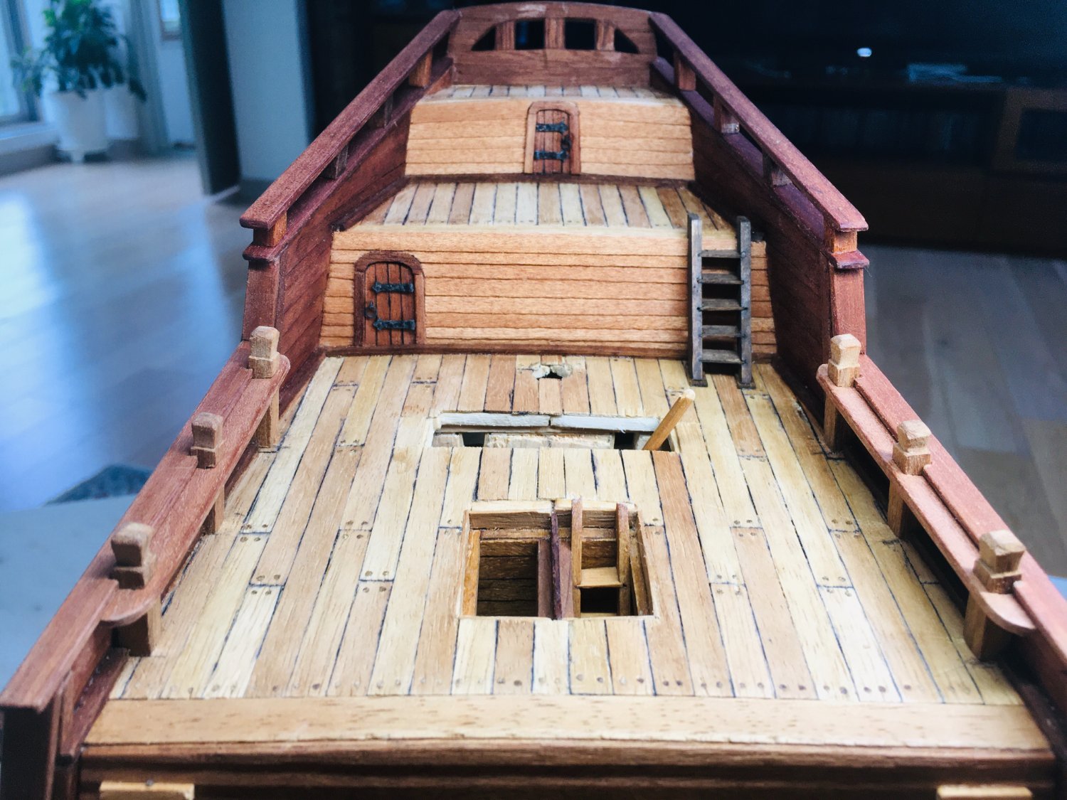
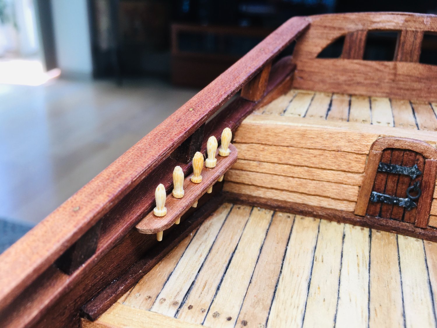
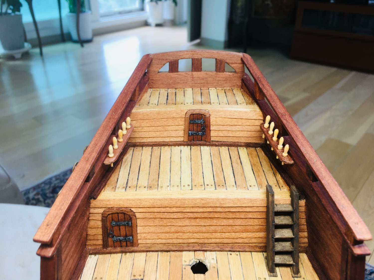
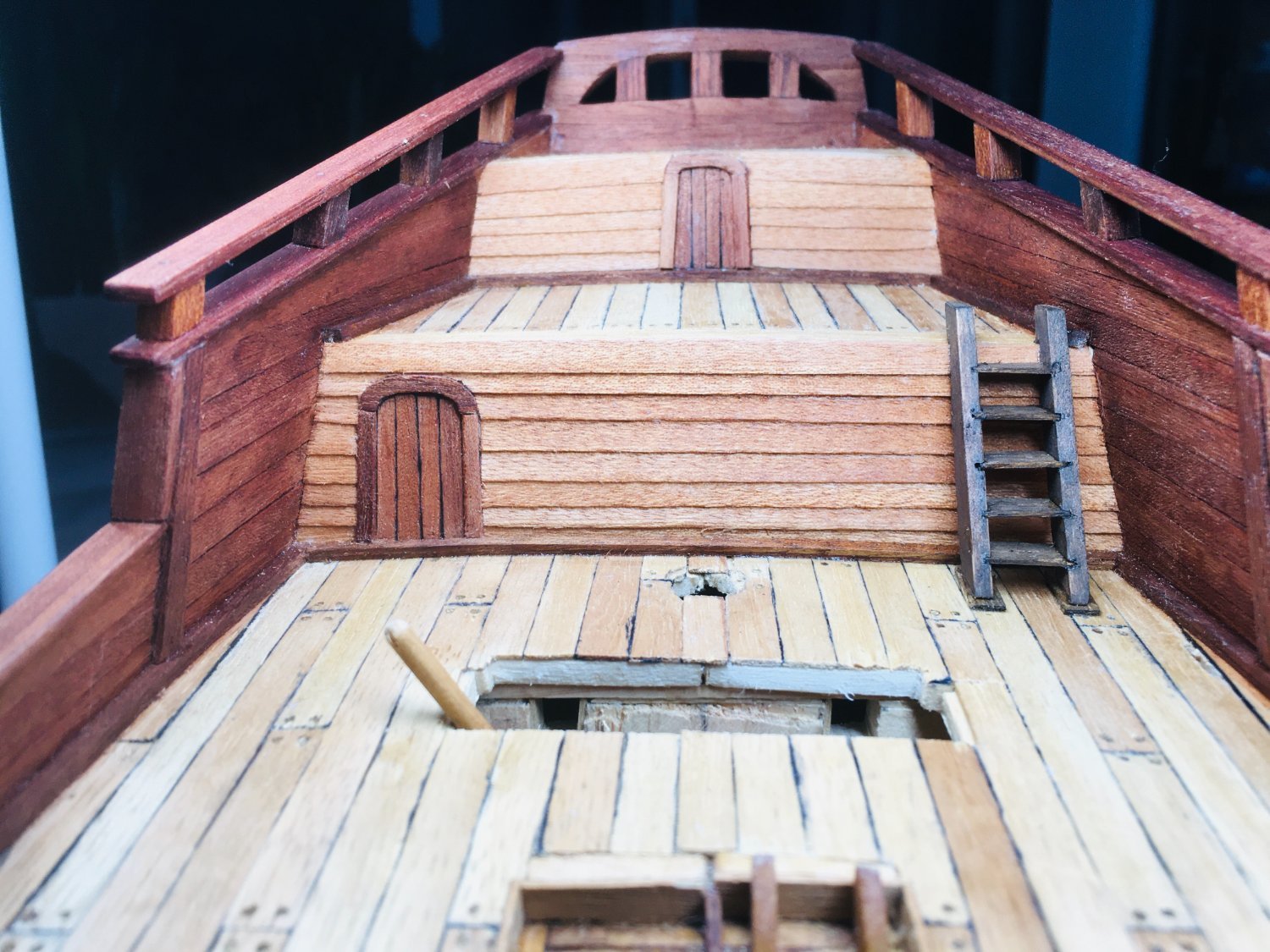
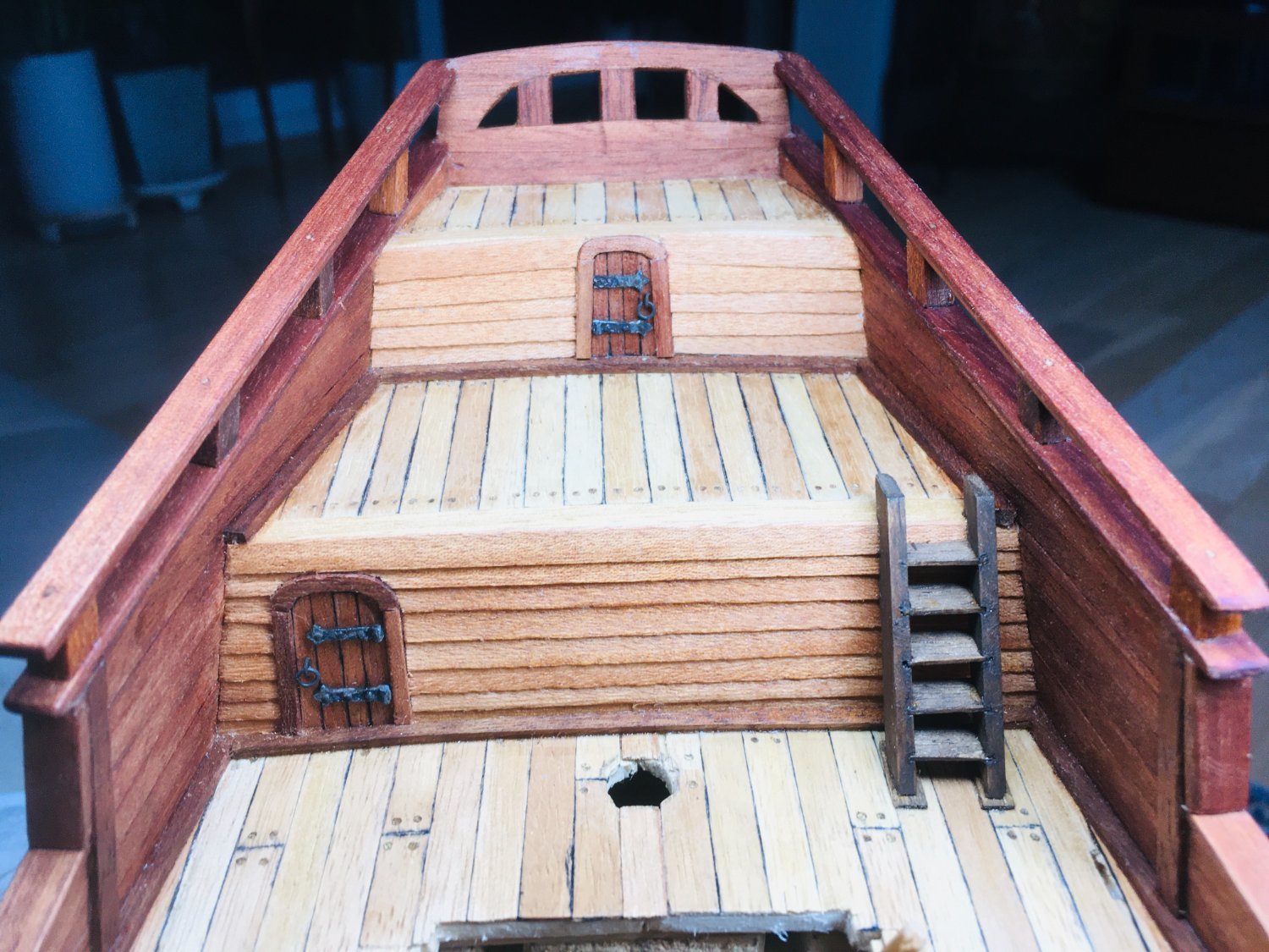
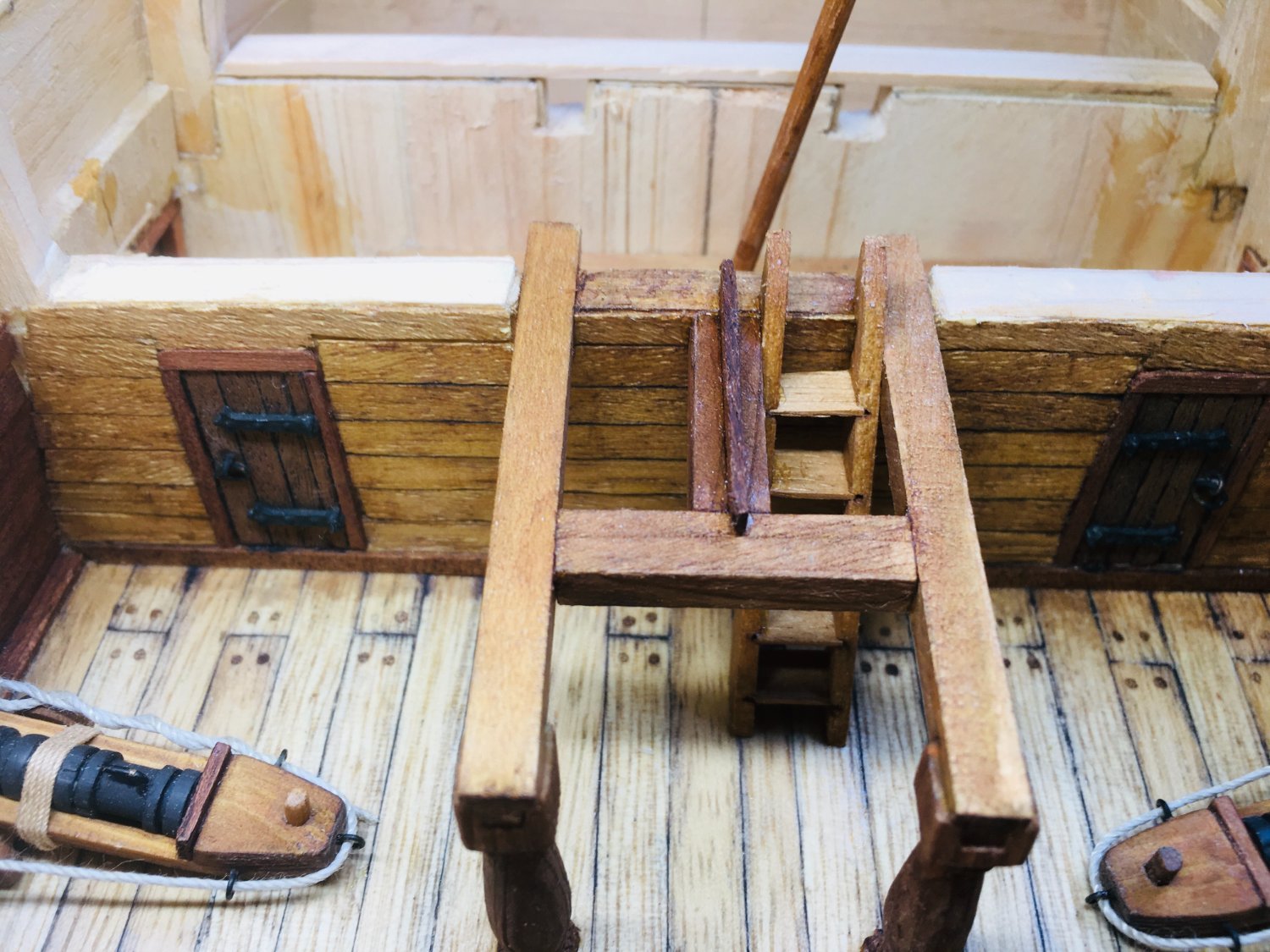
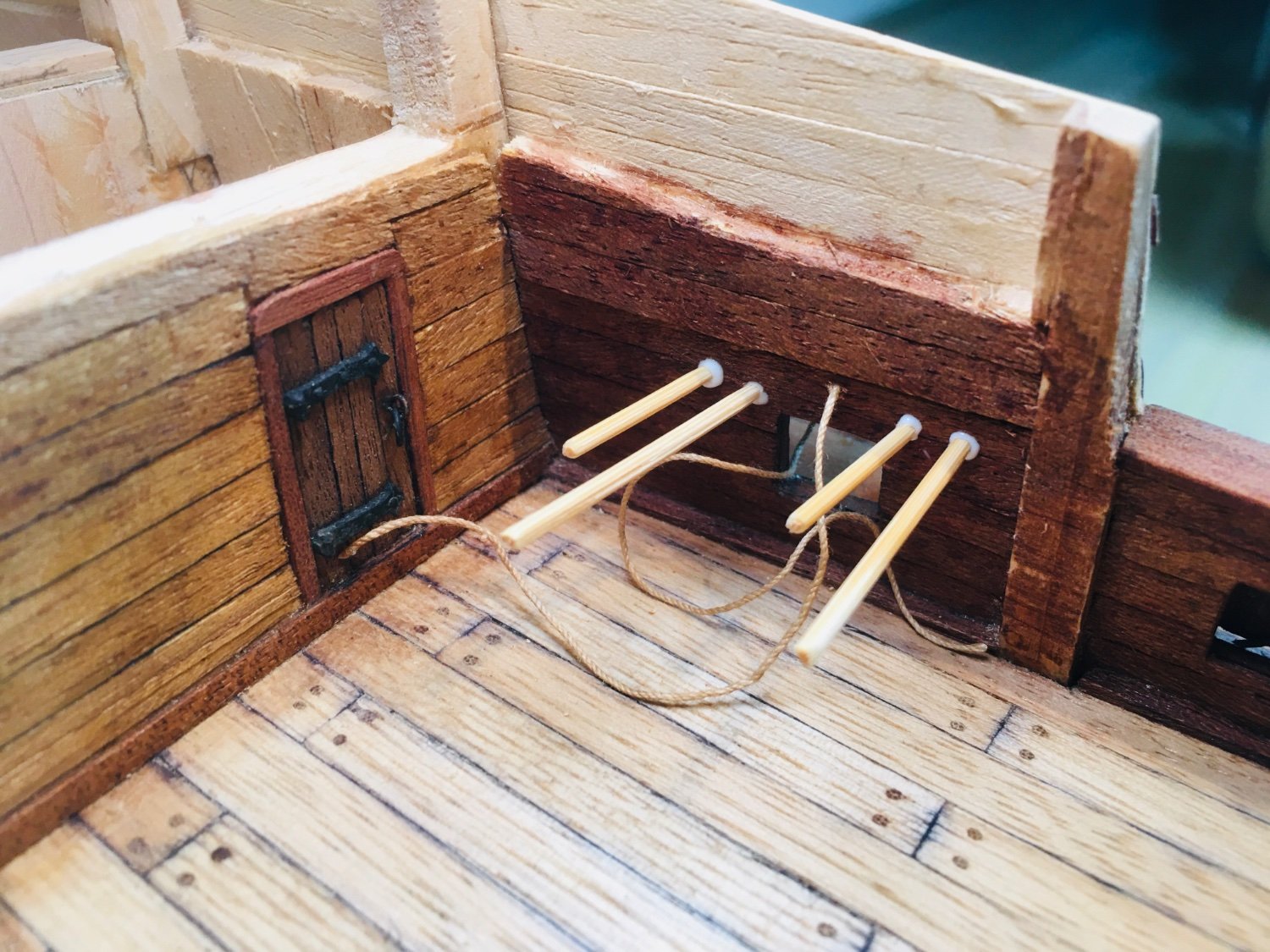
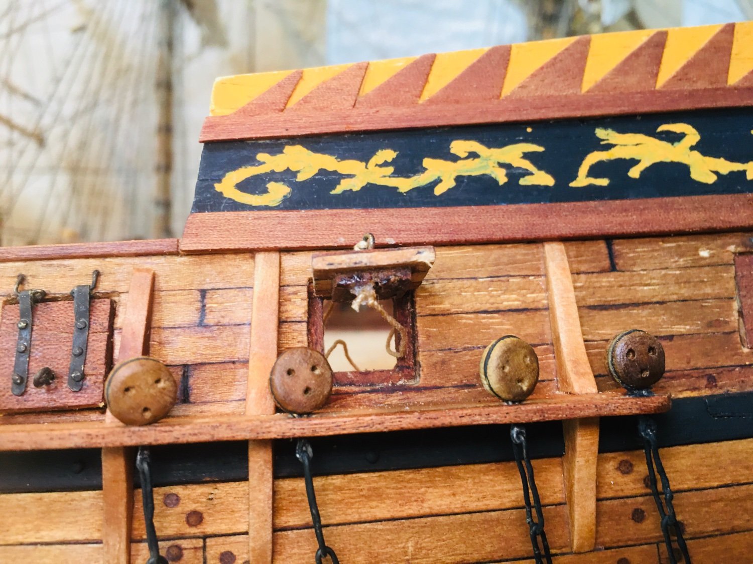
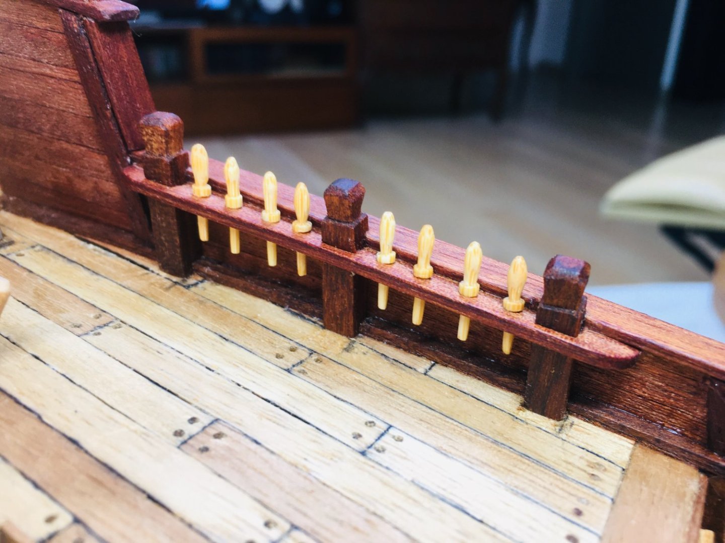
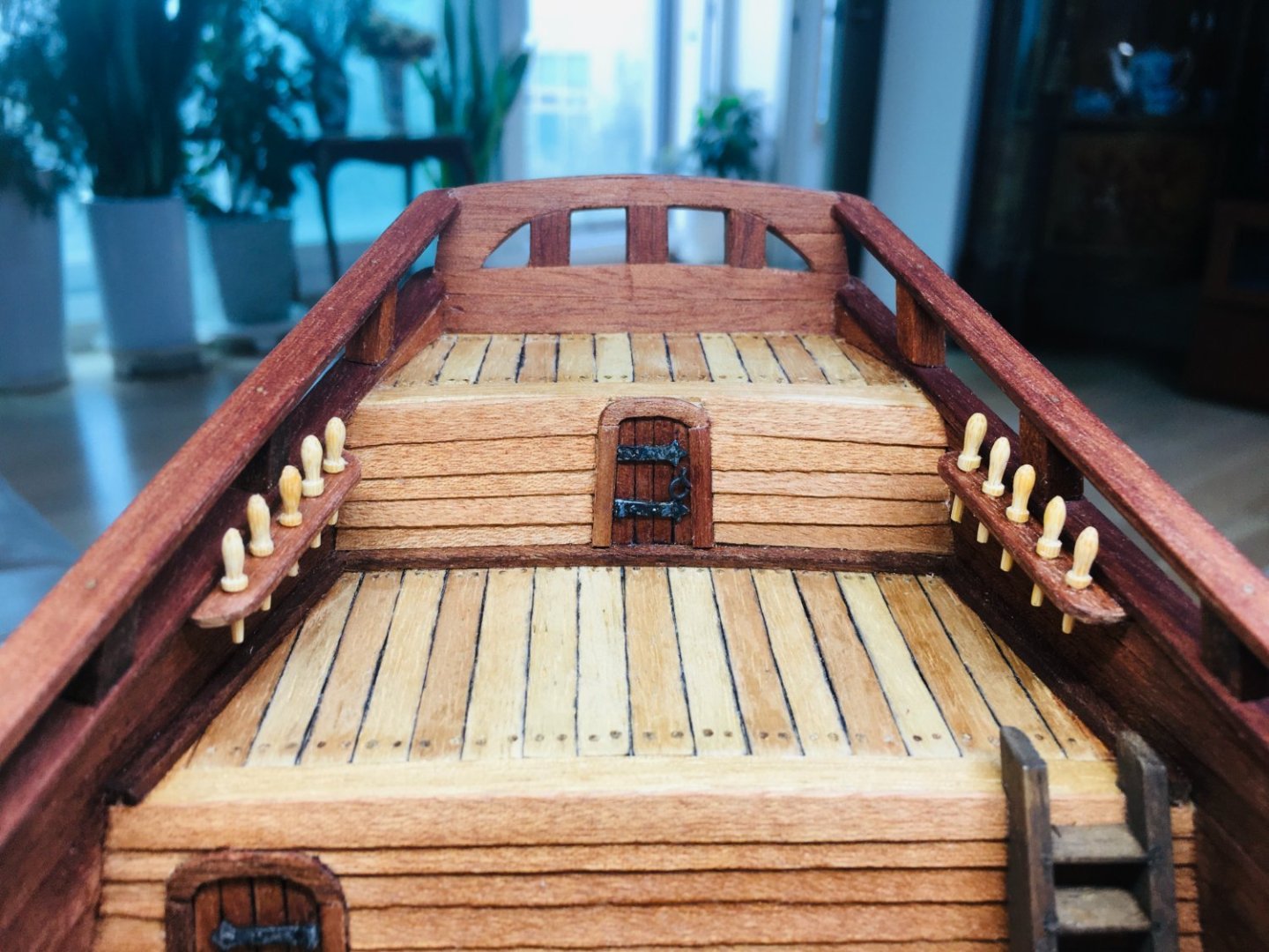
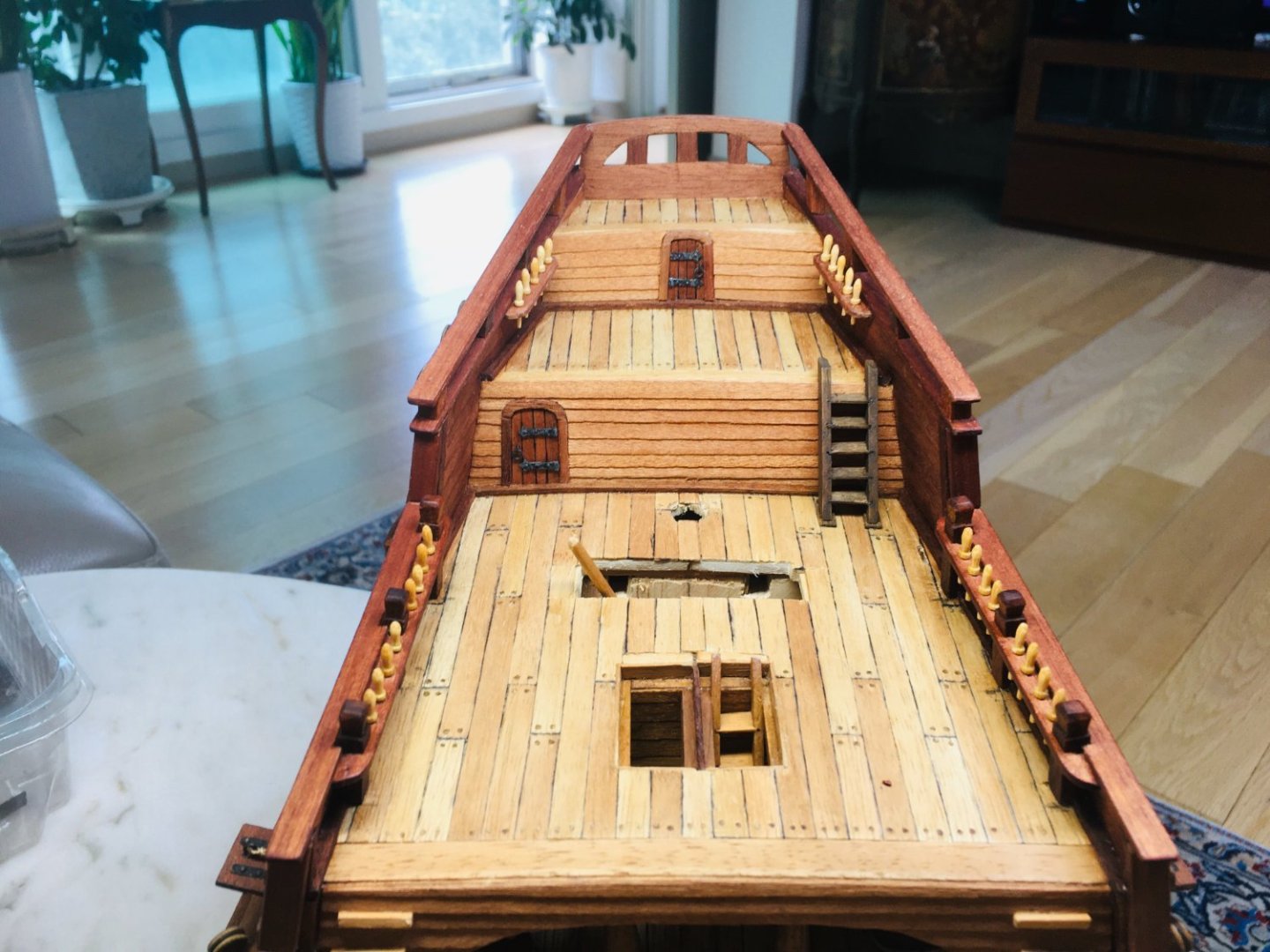
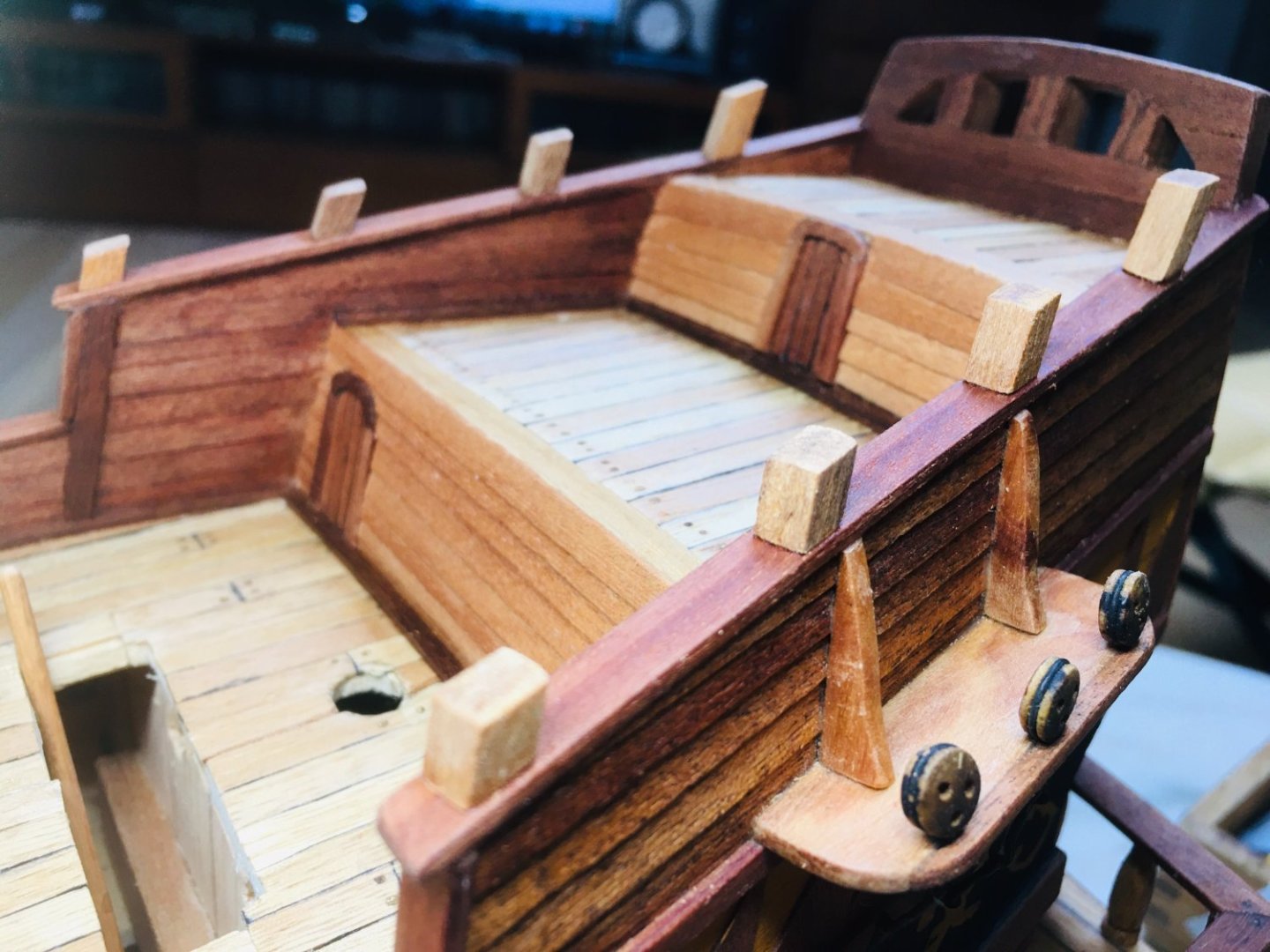
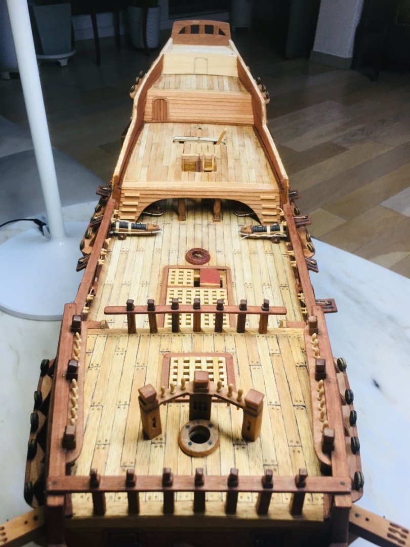
Hi all~ It's been a while since my last visit - have been tied up with something. Anyway, work on the upper decks continued. I tried walnut color stain for the ladder and it tuned out quite OK. Belaying pin racks are once again done using decommisioned hard wood chopsticks. Below are some progress pictures.


-
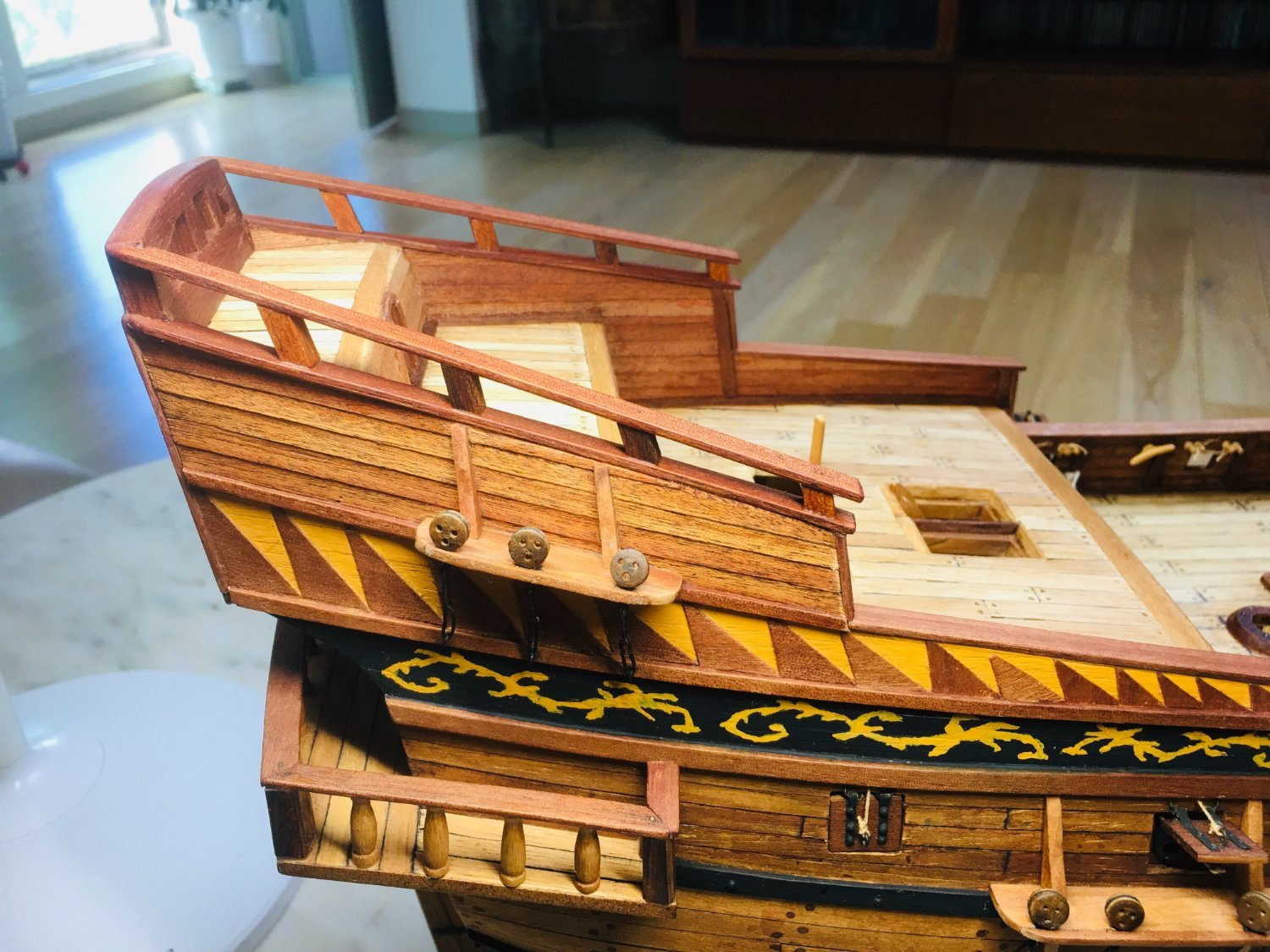
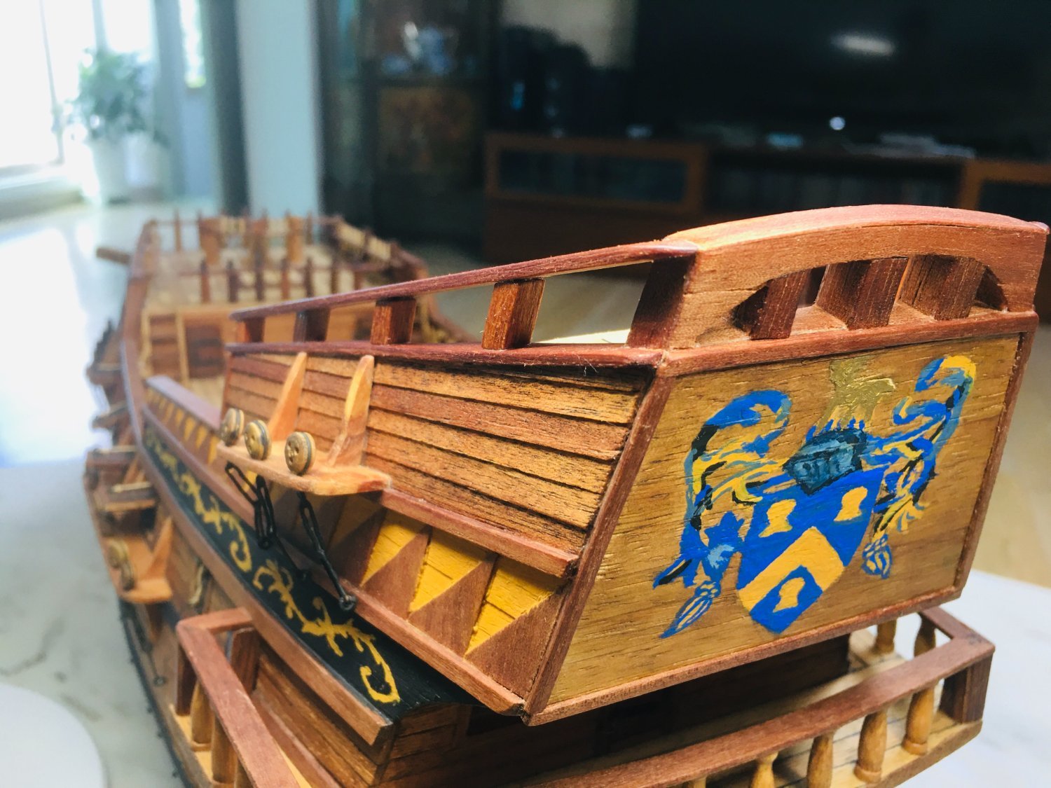
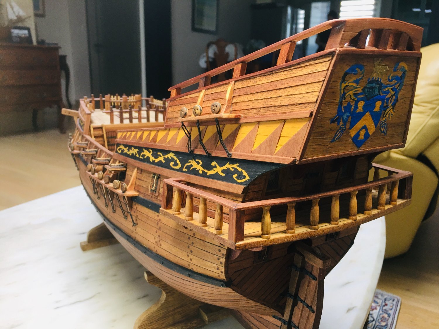
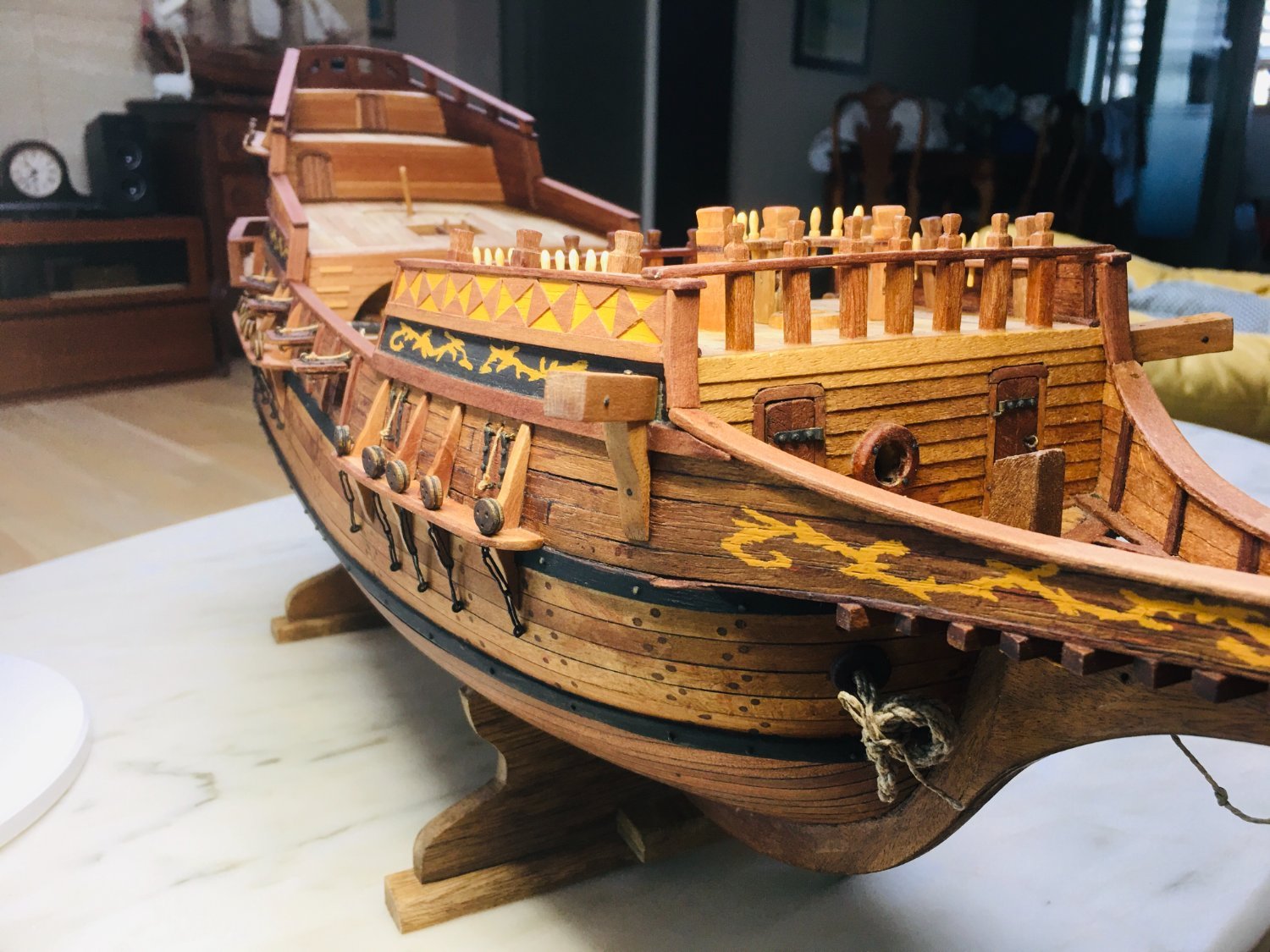
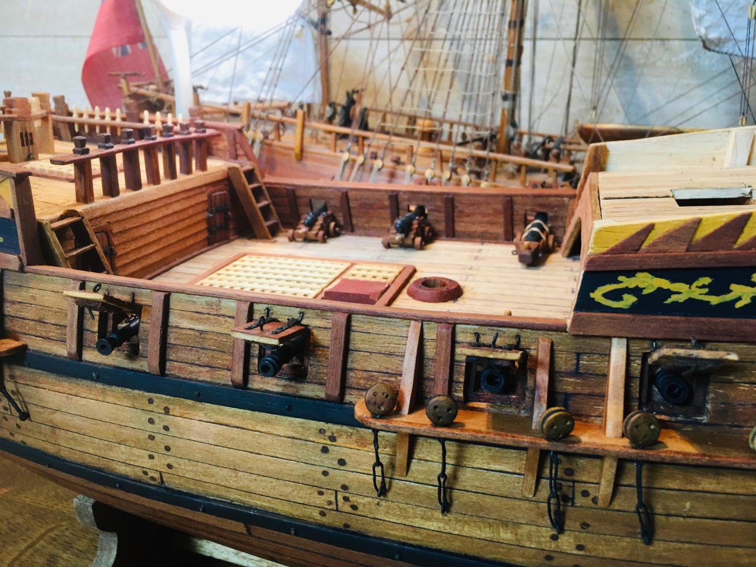
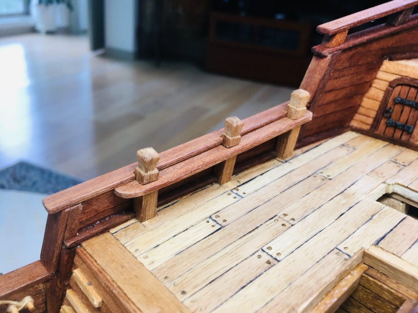
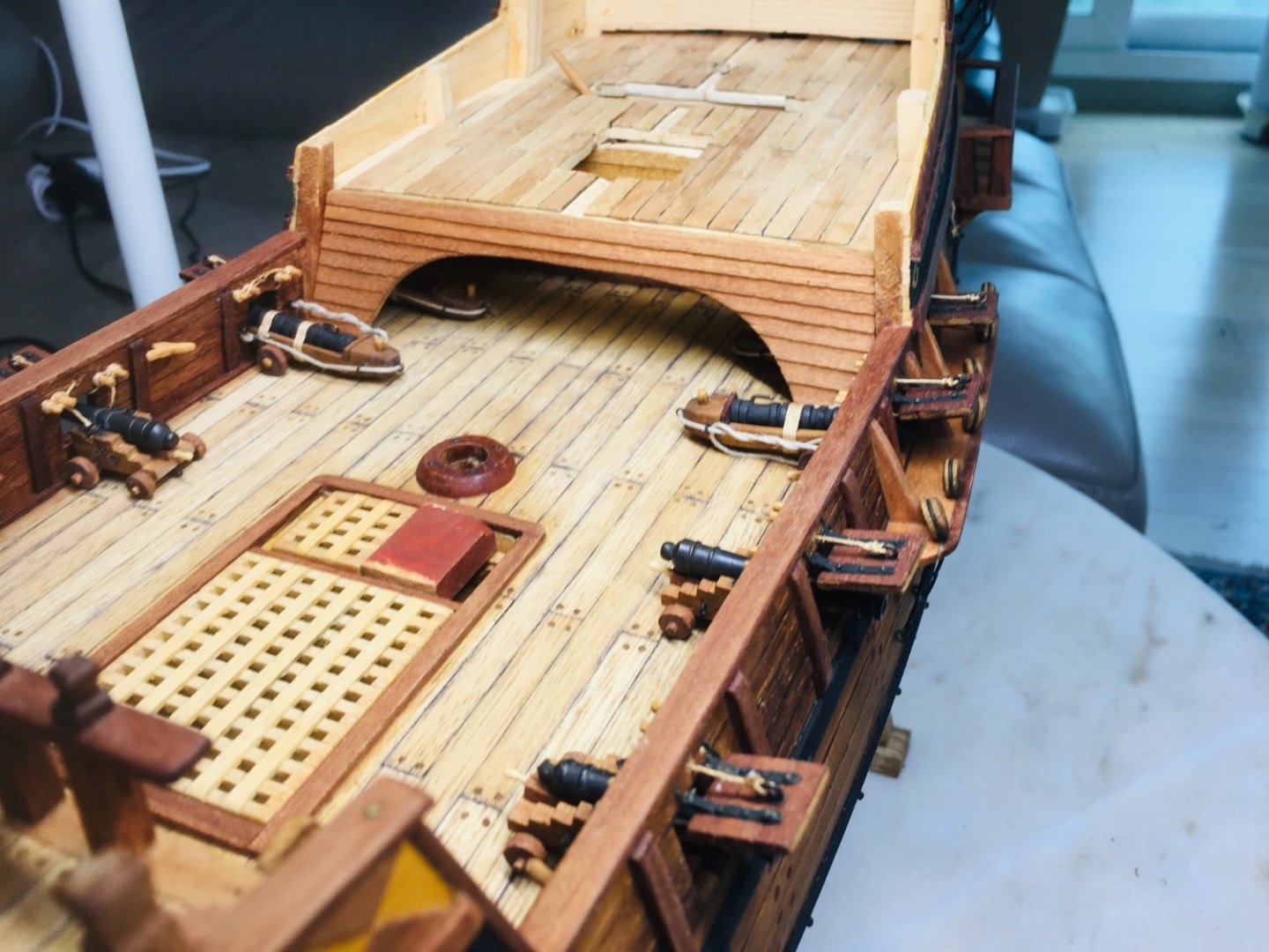
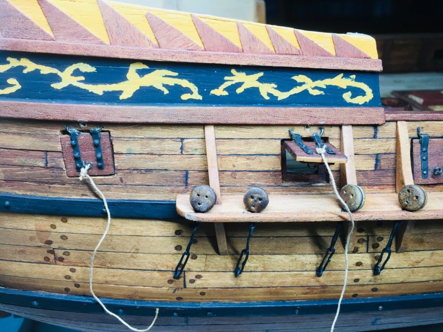
And finally, I put the rails in place. So, work on hull itself (or outer hull) seems to be pretty much done. Next will be the works vis-a-vis filling in the inside of the decks with various structures as well as cannons. Still long way to go until I can finally begin with masts and rigging.


-
Some more pictues~


-
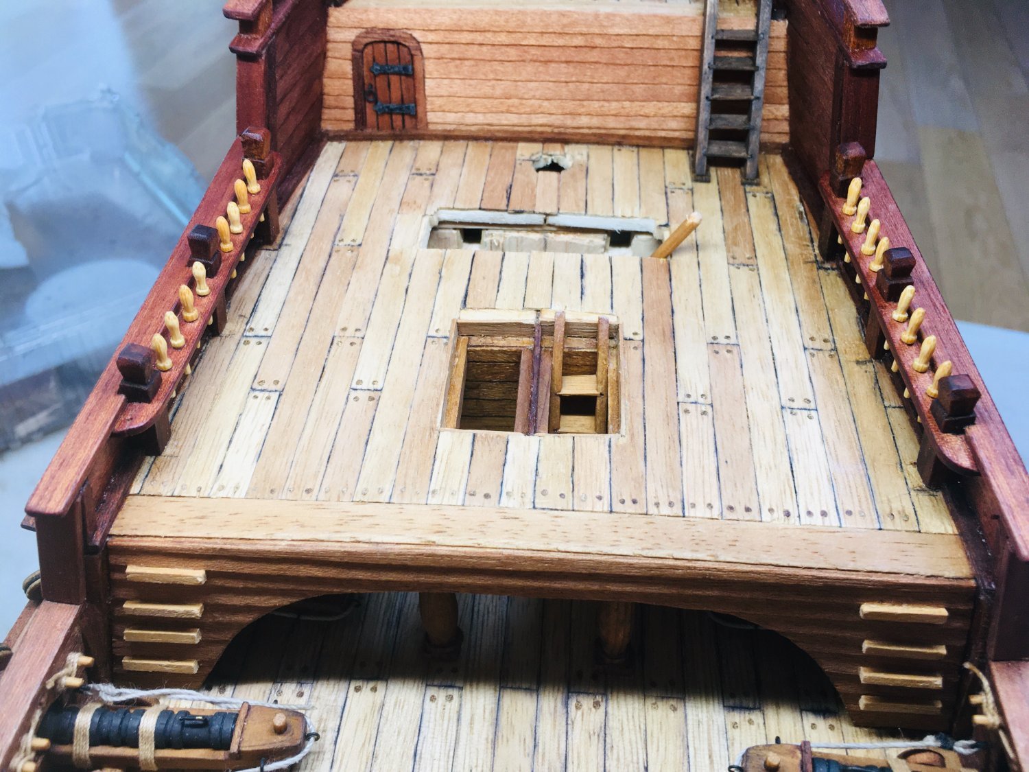
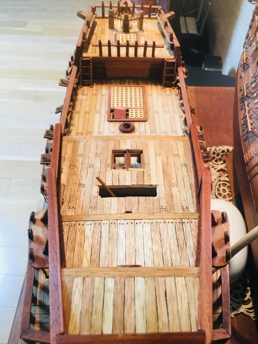
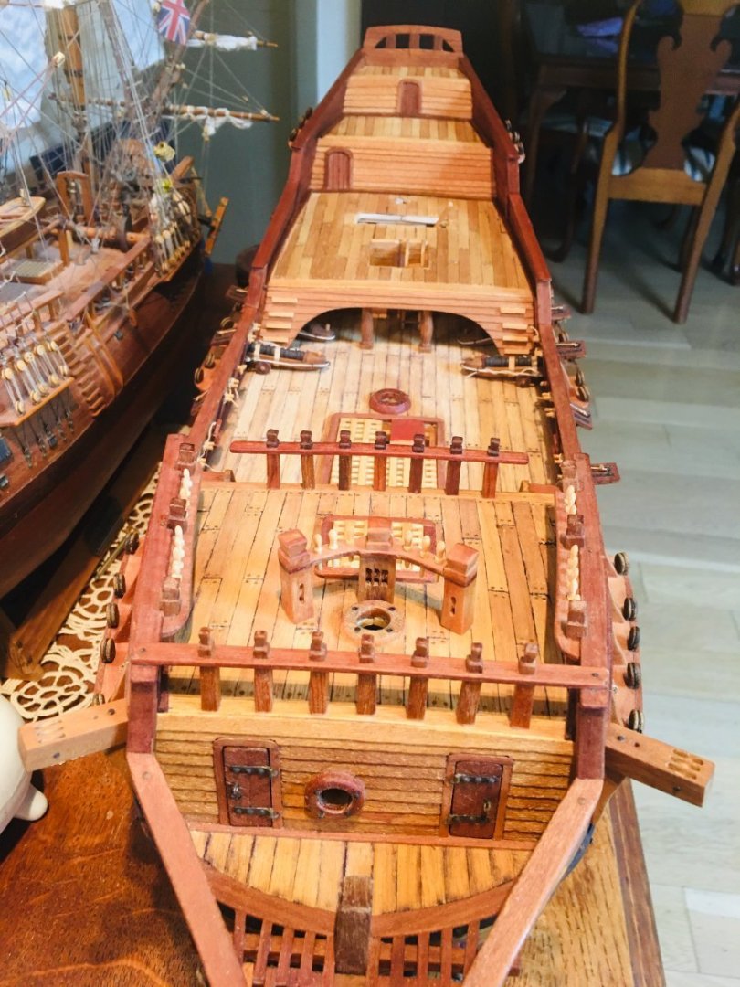
Hi All~ Work continued on the final deckwork in the quatredeck and poop deck areas. Just generic stuff, so nothing much to comment or to explain. Below are the latest work stream pictures.


-
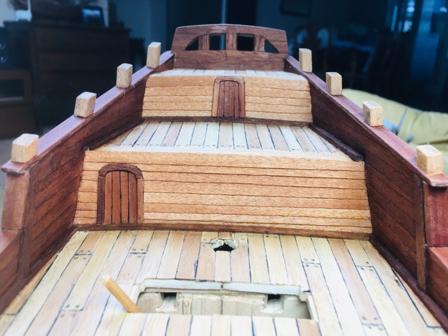
Finalizing the initial quarterdeck work - glueing things in place, installing additional features..etc. Also, the poop deck area construction begins..


-
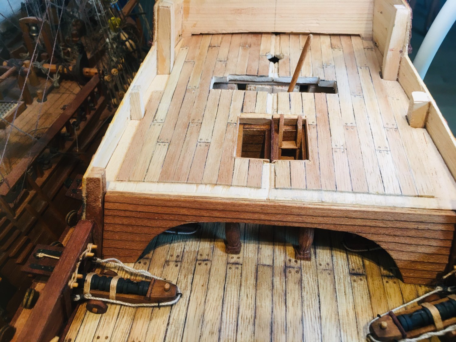
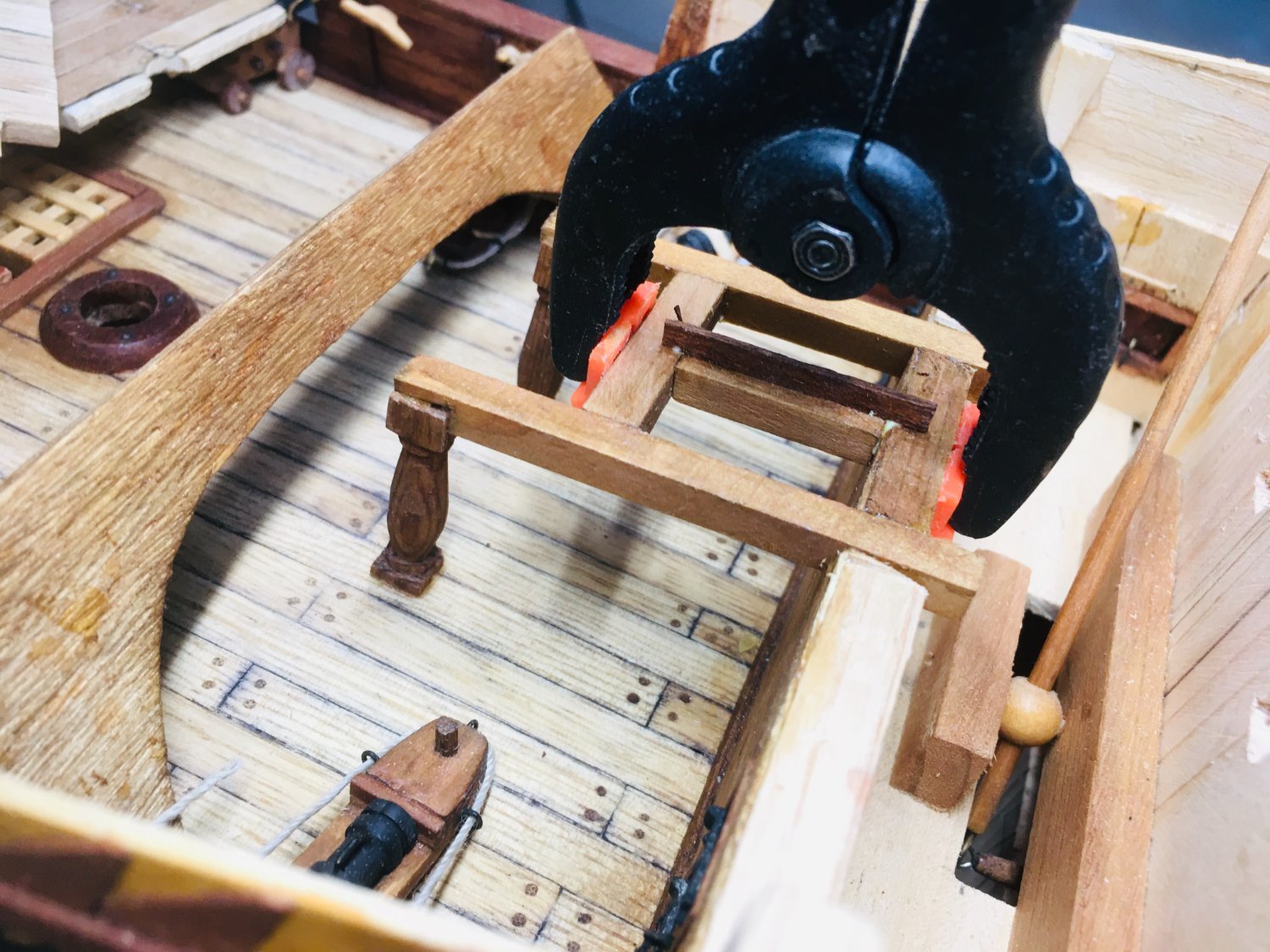
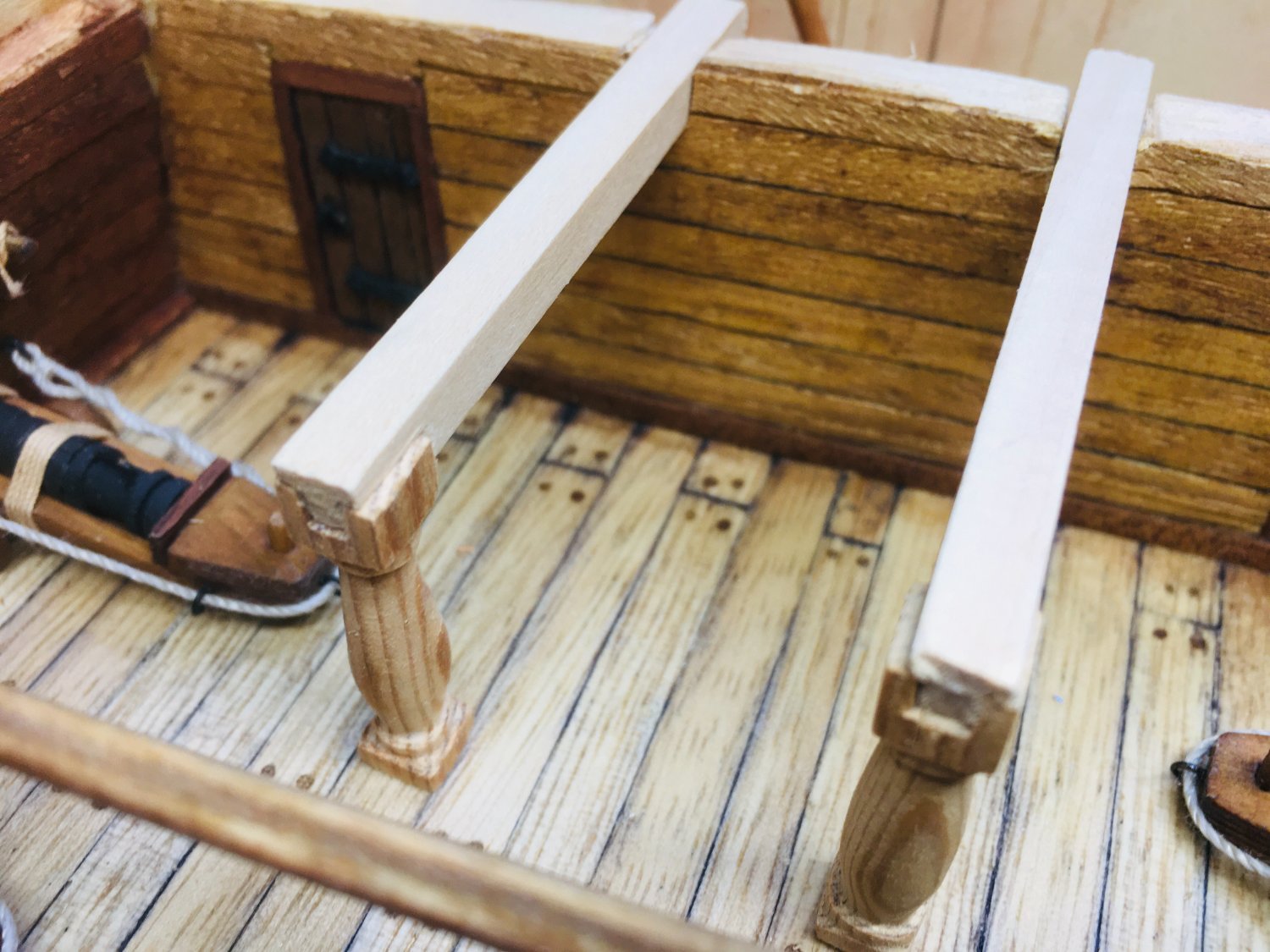
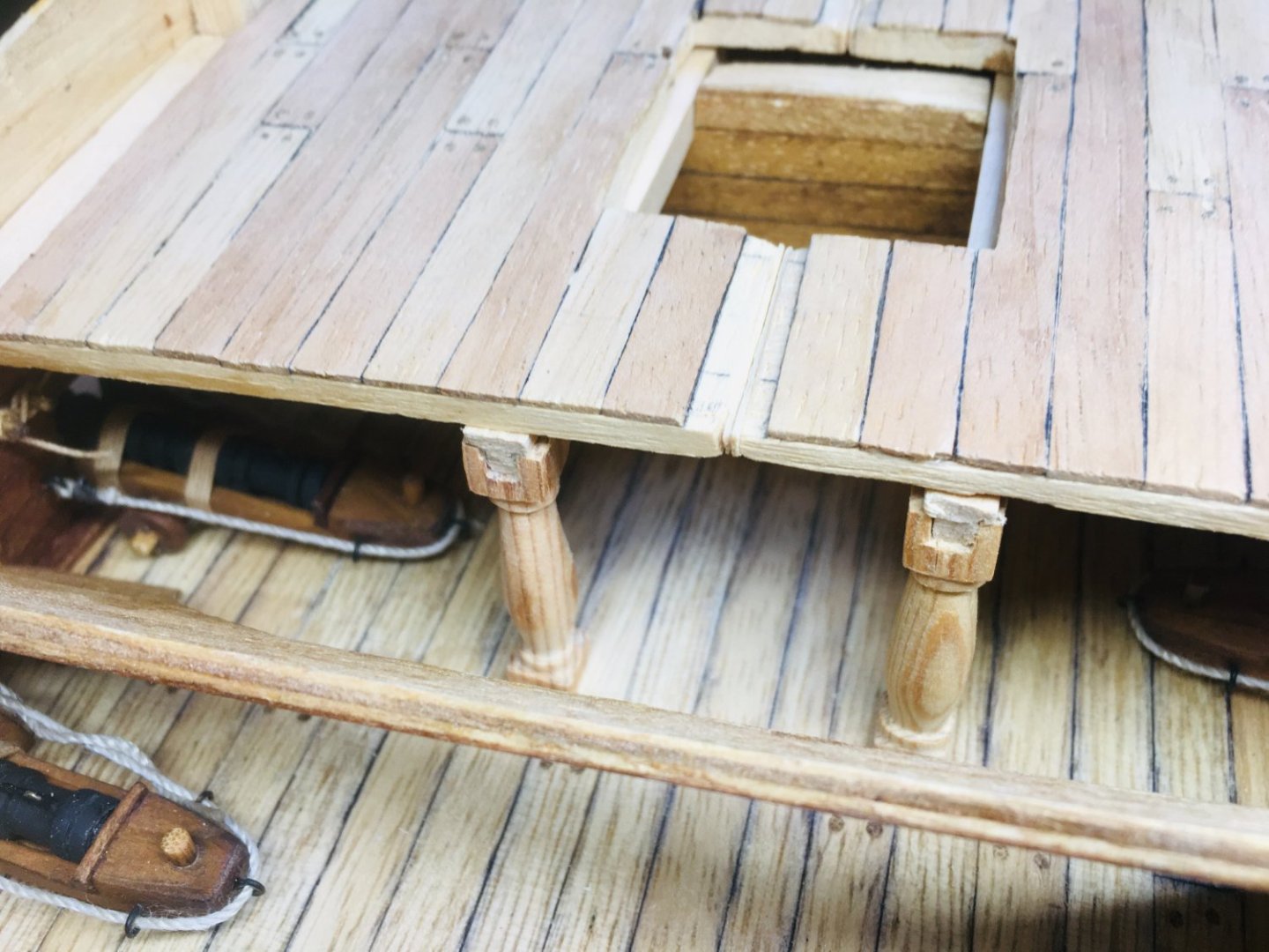
Work on the quarterdeck continues...dyeing the pillars and support beams, making and installing a ladder,


-
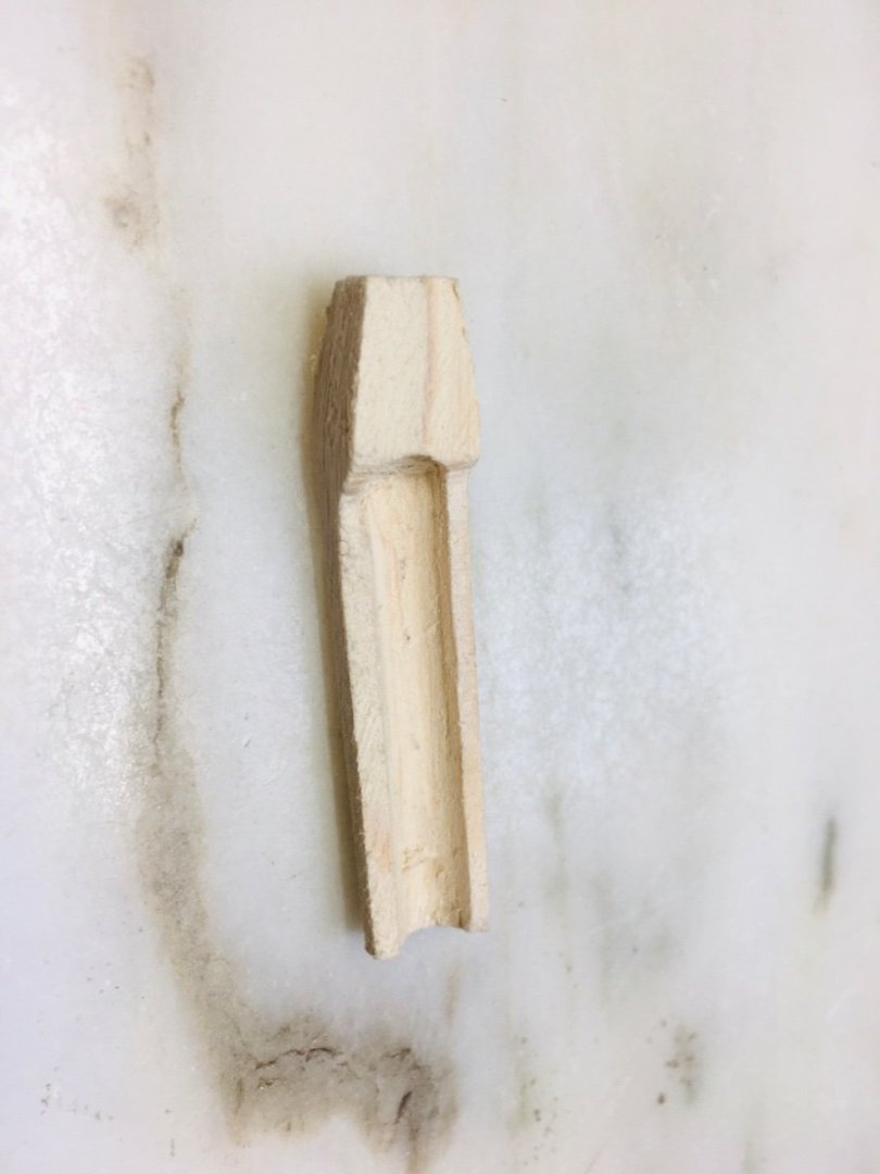
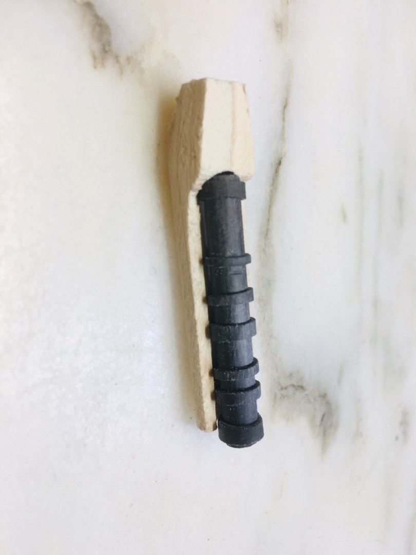
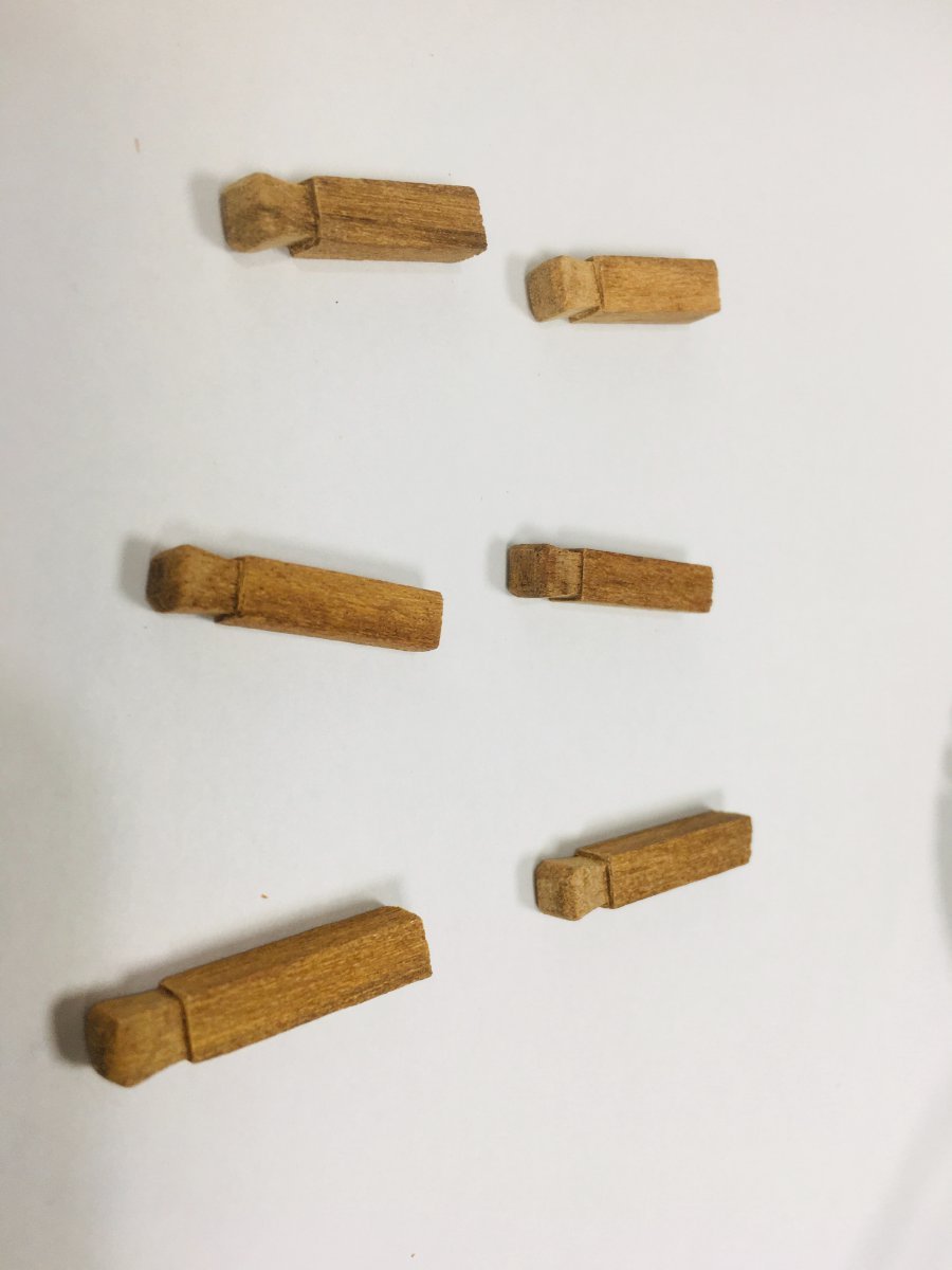
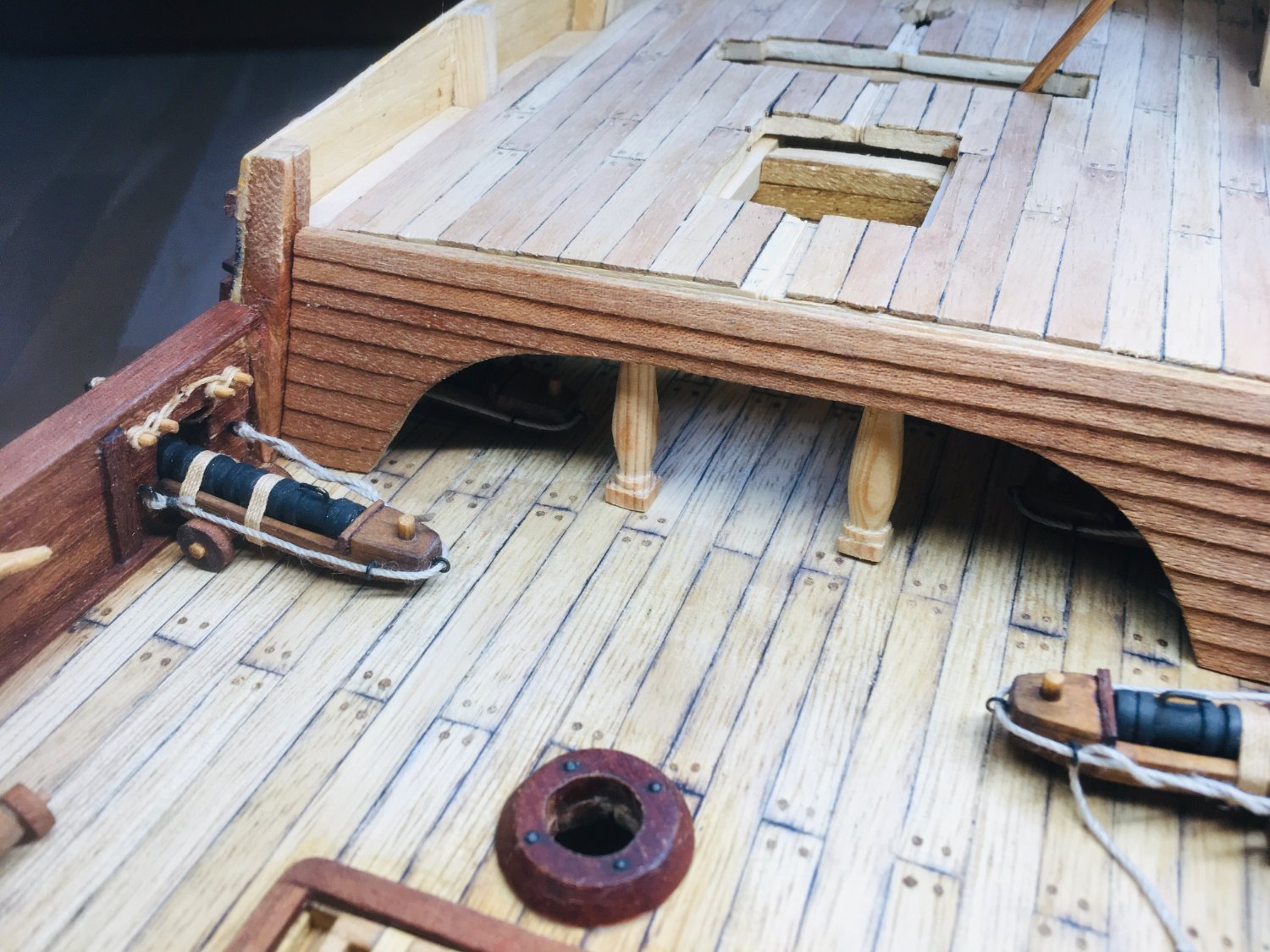
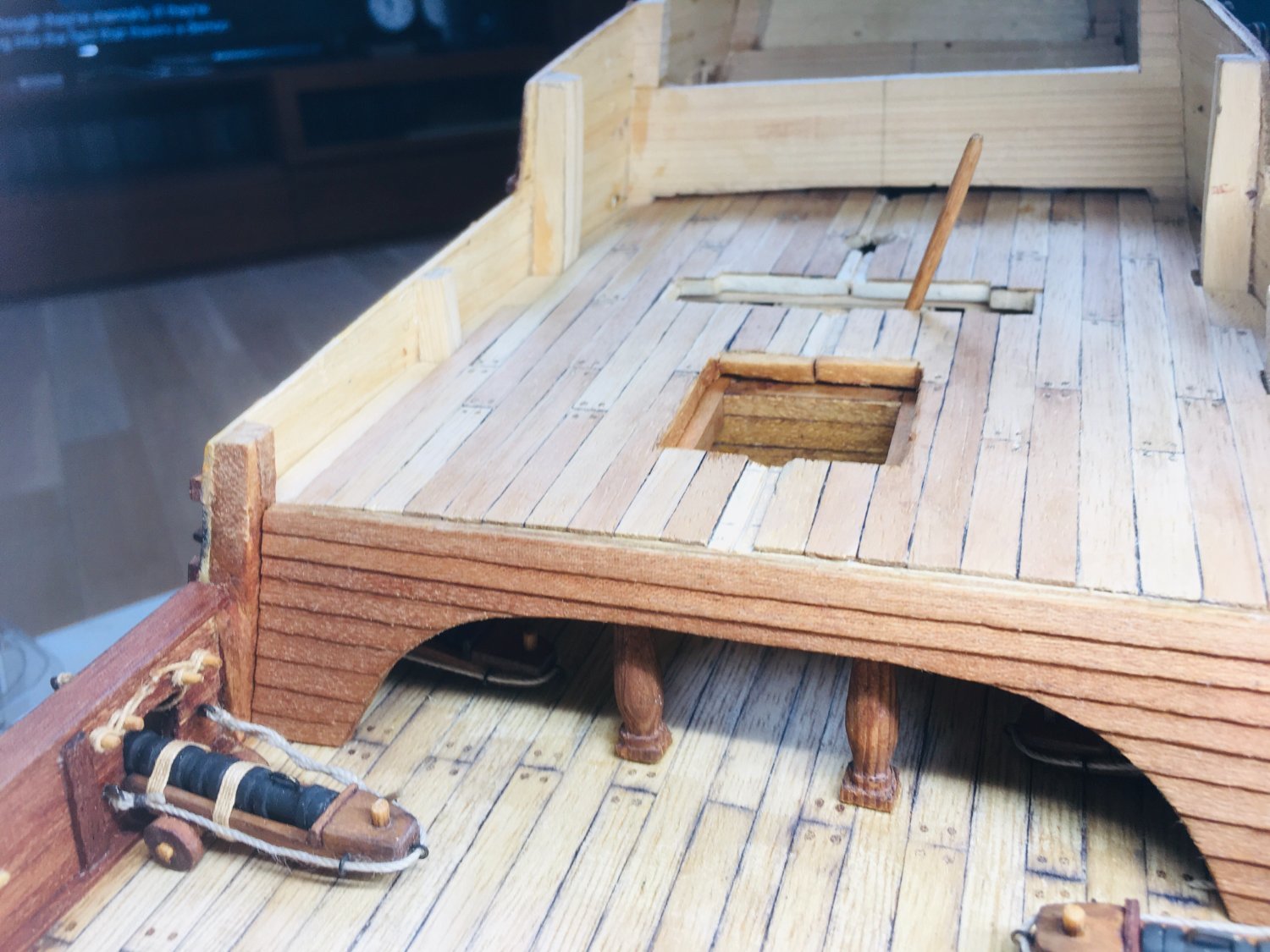
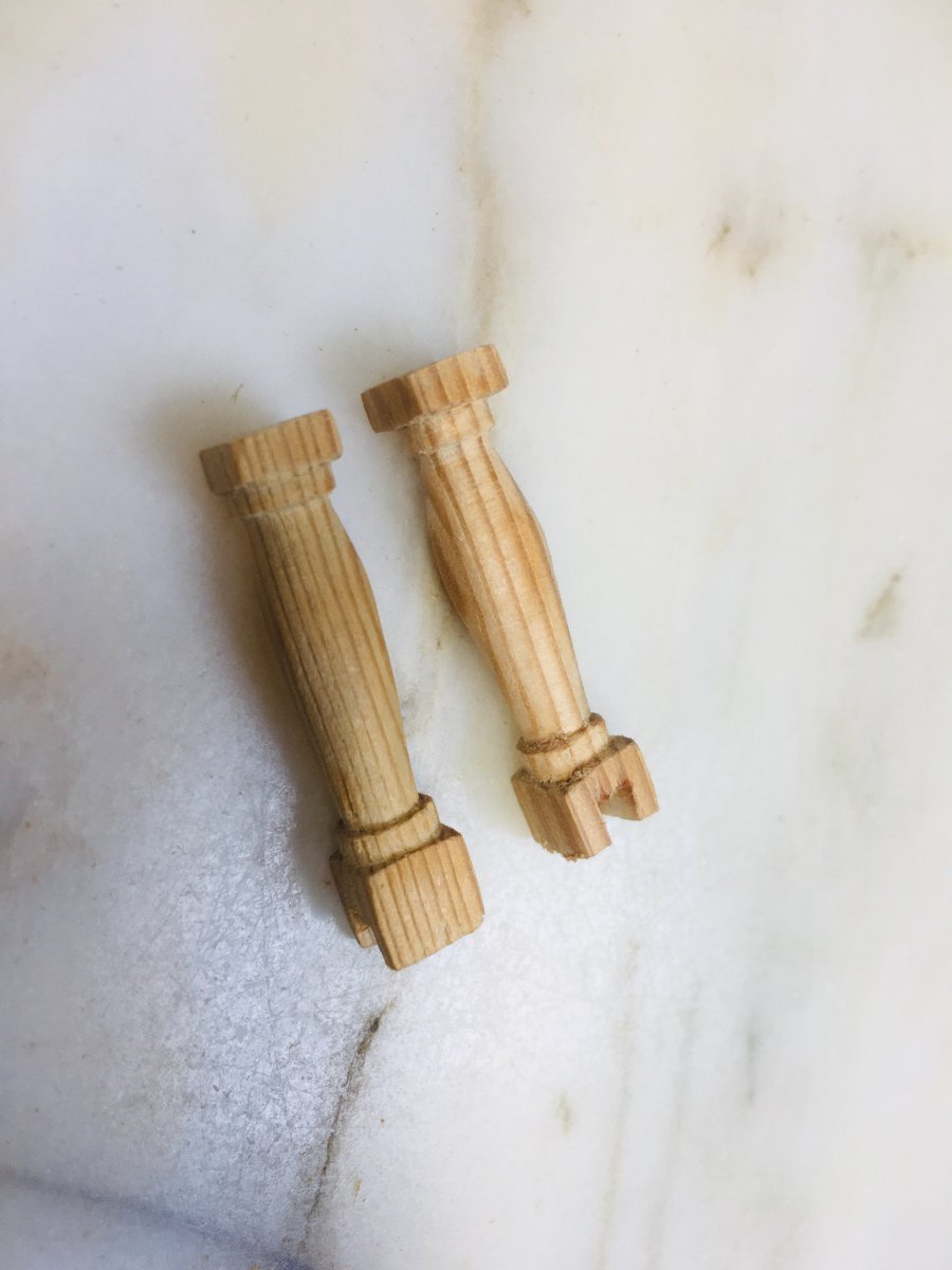
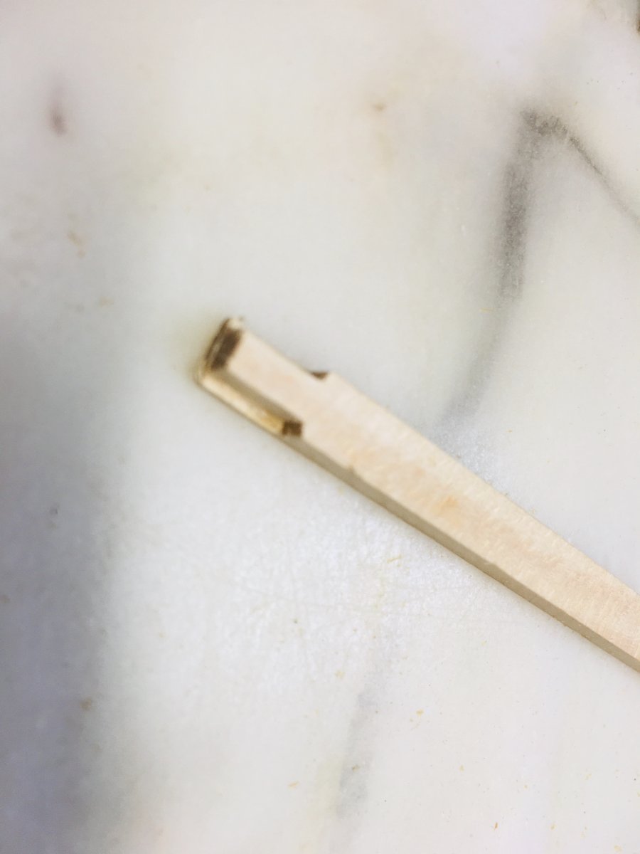
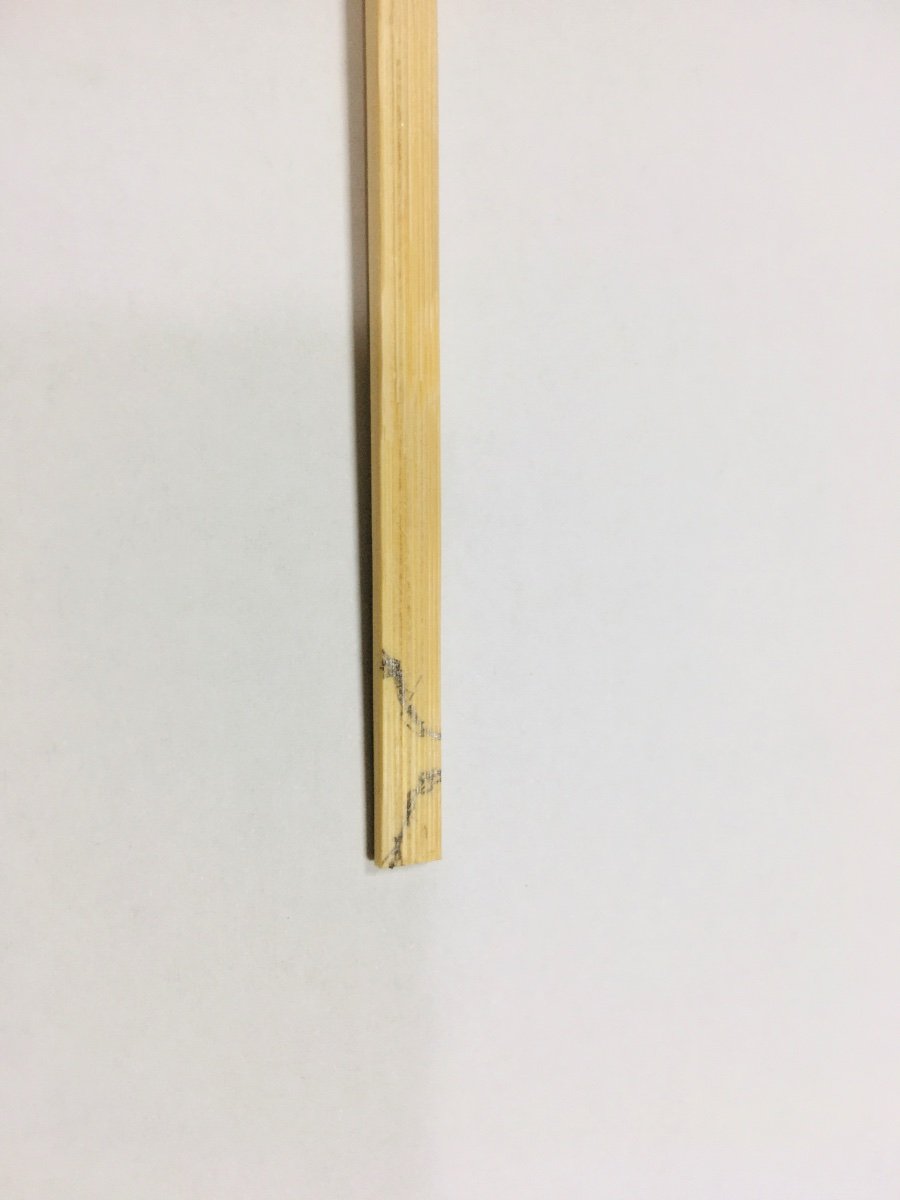
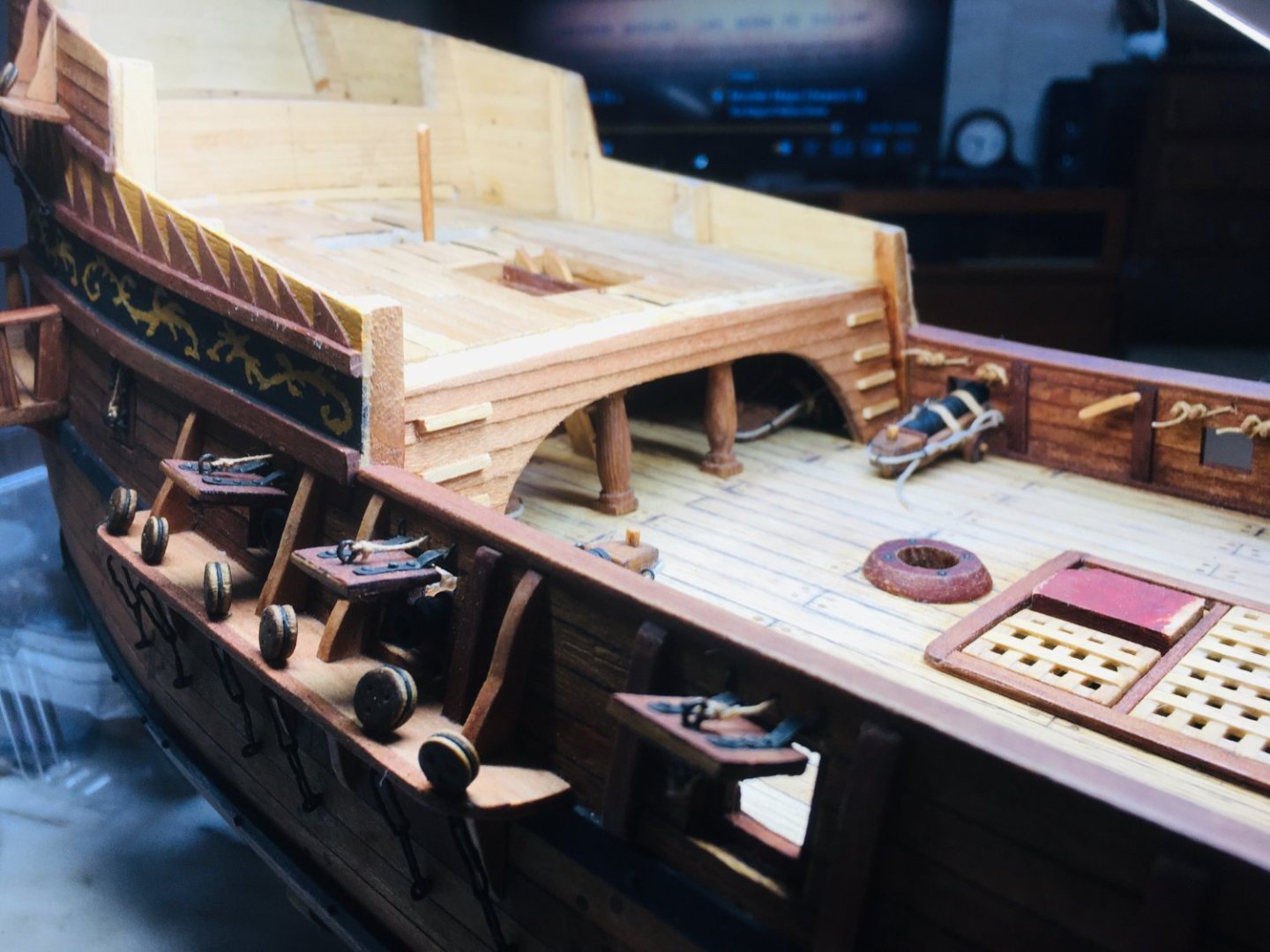
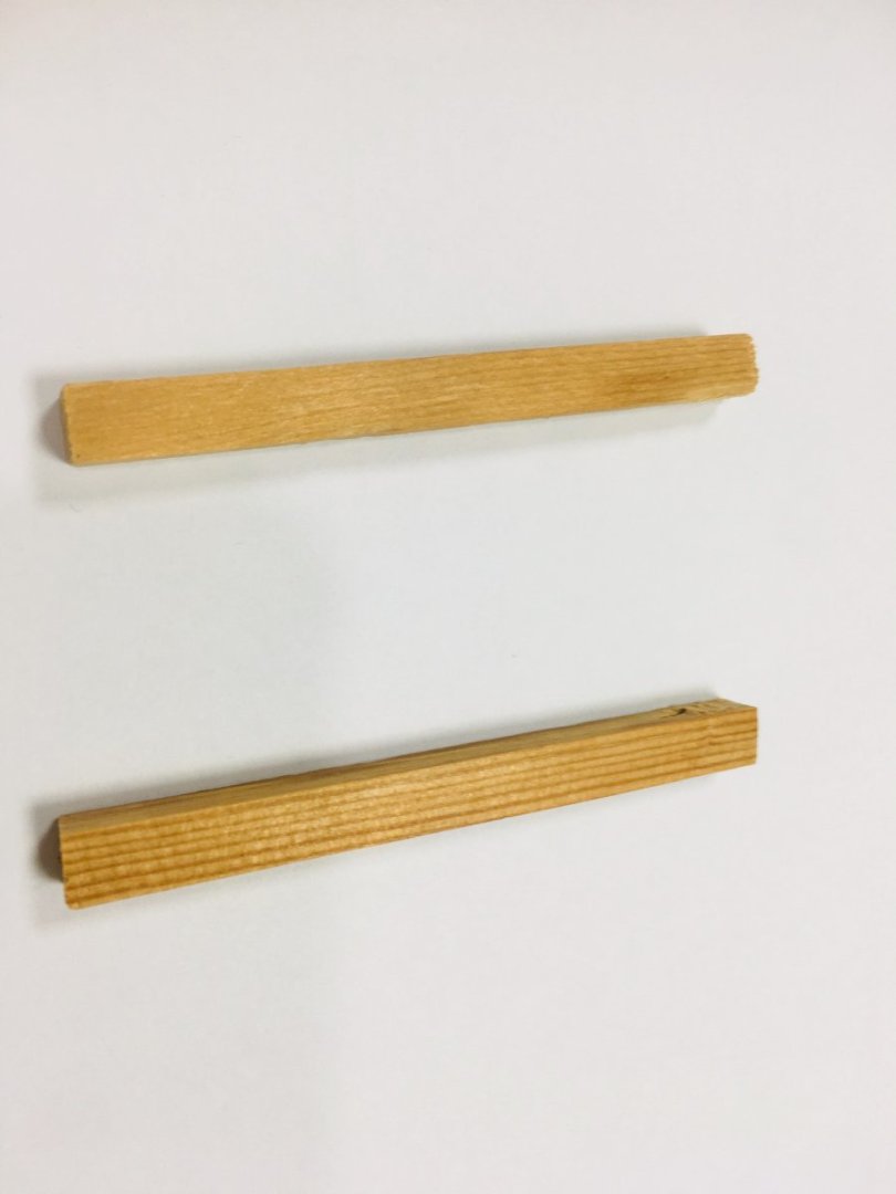
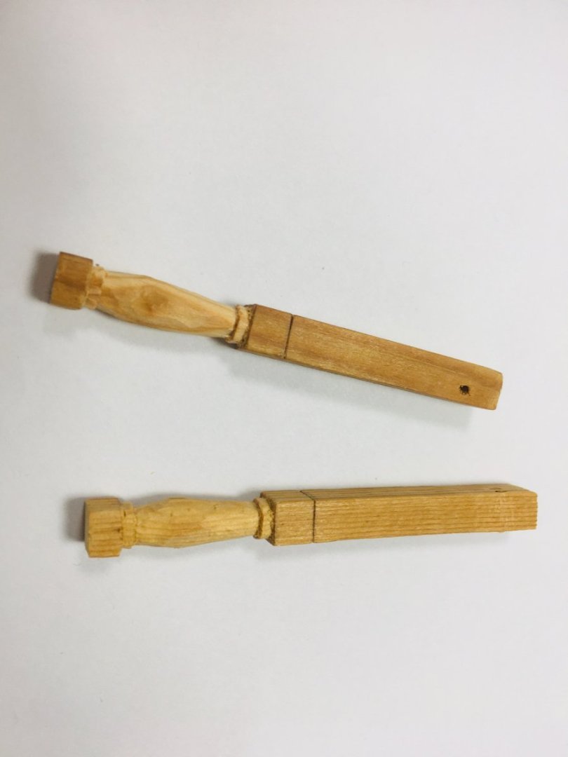
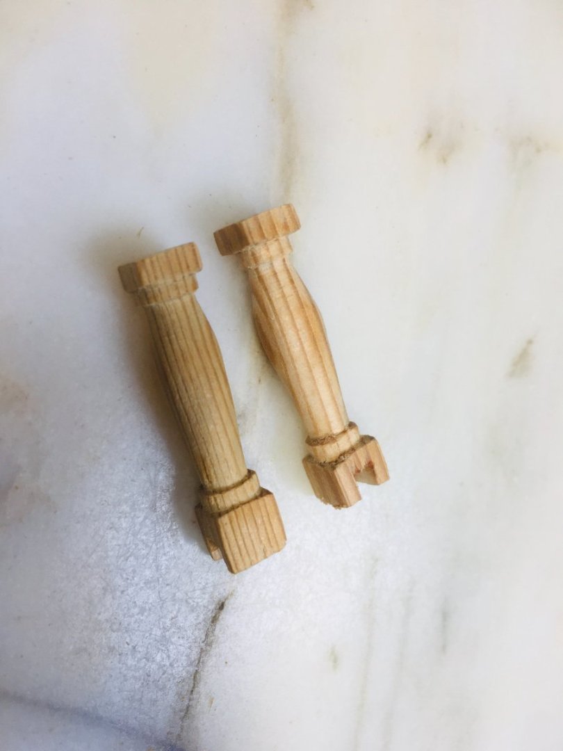
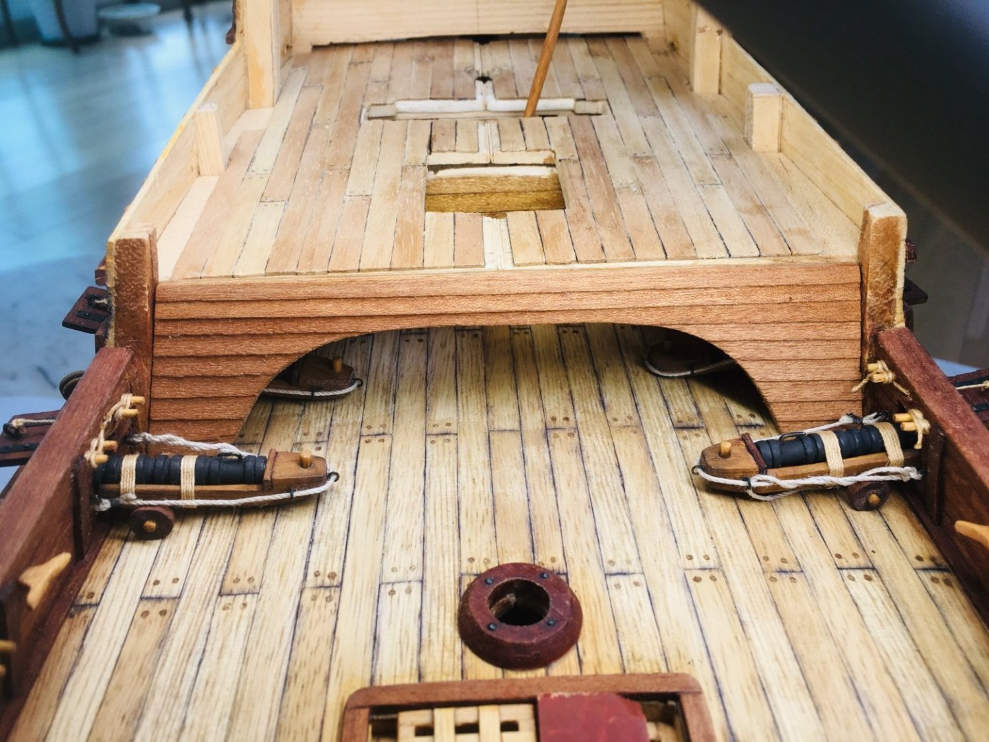
Hello shipmates~! I have temporarily paused work on cannons and moved on to quaterdeck and poop deck work. The demi culverins will be installed after all the deck works are finished. I have come up with a simple design where two pillars (and 2 short cross beams) will support the quarterdeck (in the midship area). I realize that this particular design may deviate from a historically accurate method of constructing pillars and deck support, but I am reserving a more historically acceptable (or correct method) for GH2 and onwards as the lower quarterdeck area from GH2 onwards will feature much more open space and thus more realistic rendition/construction will be required anyway. For the pillars, I decided to try rectangular soft wood pieces that were originally salvaged from my wife's dish dryer (from IKEA). These pieces were used to build a large cage for my daughter's pet quail when wife decided to decommision the wooden dish dryer. So, these soft wood pieces have been recyled and repurposed twice already! Final life of these soft wood pieces as pillars supporting a wooden model ship deck begins as below.


-
Thanks very much, Patrick!
-
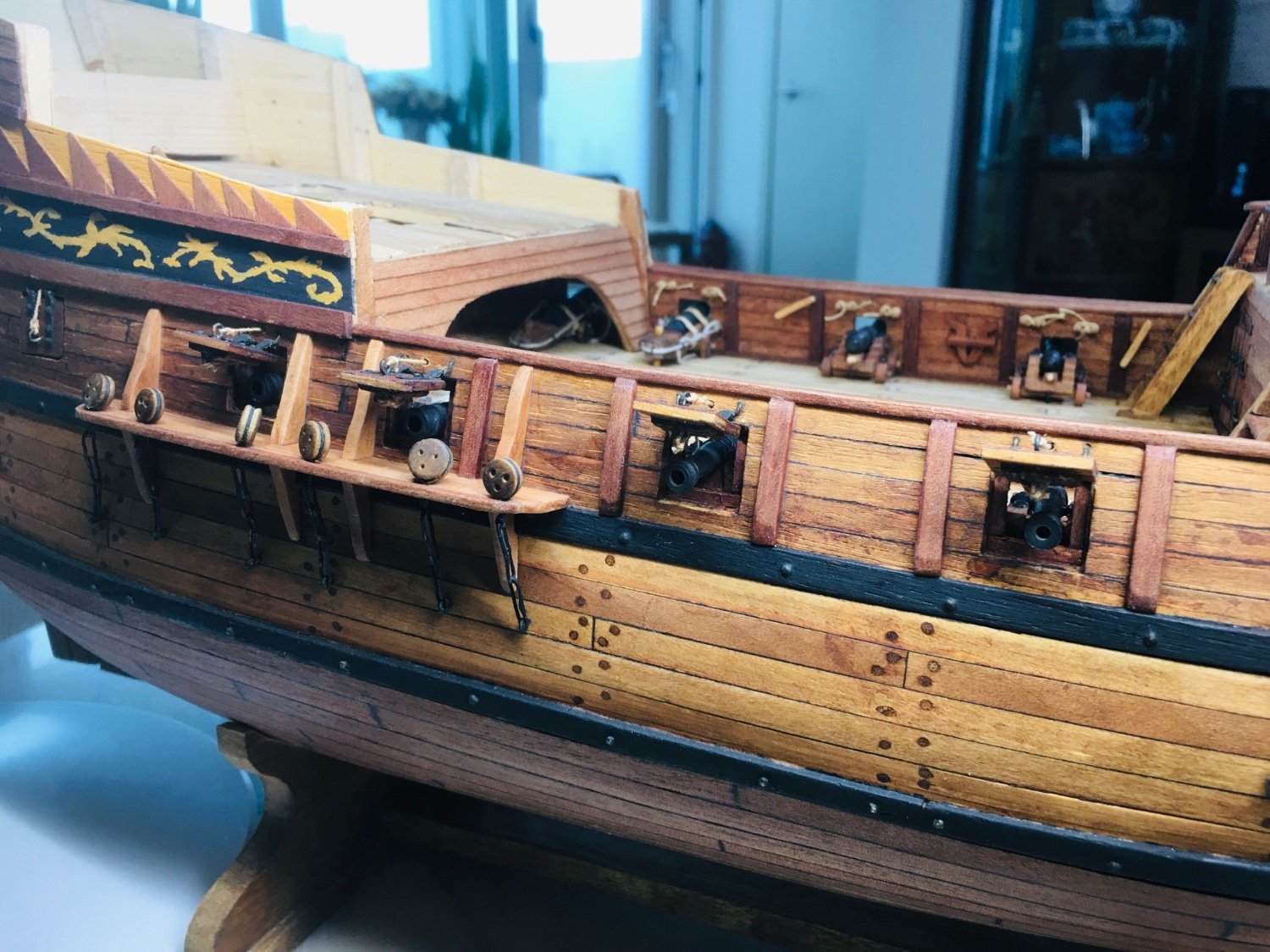
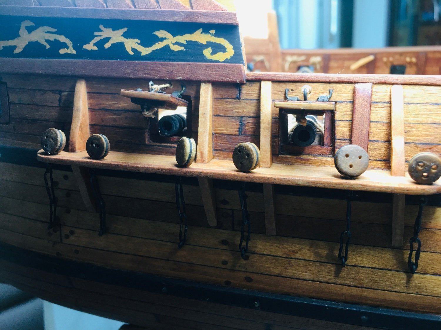
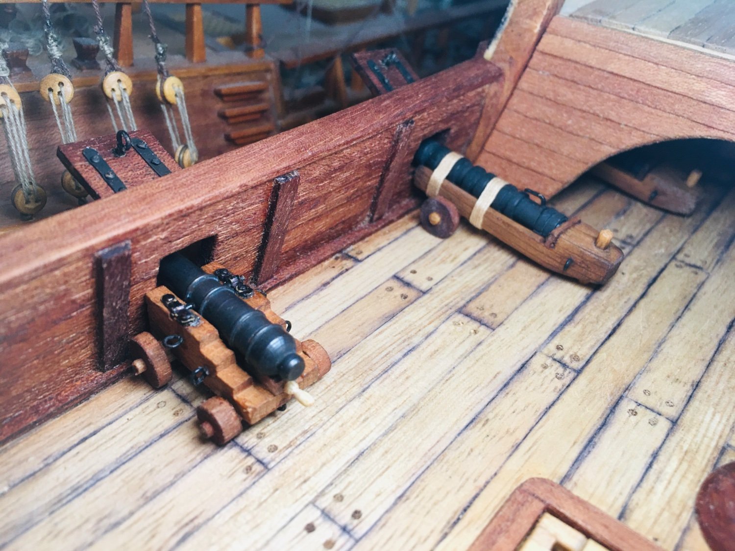
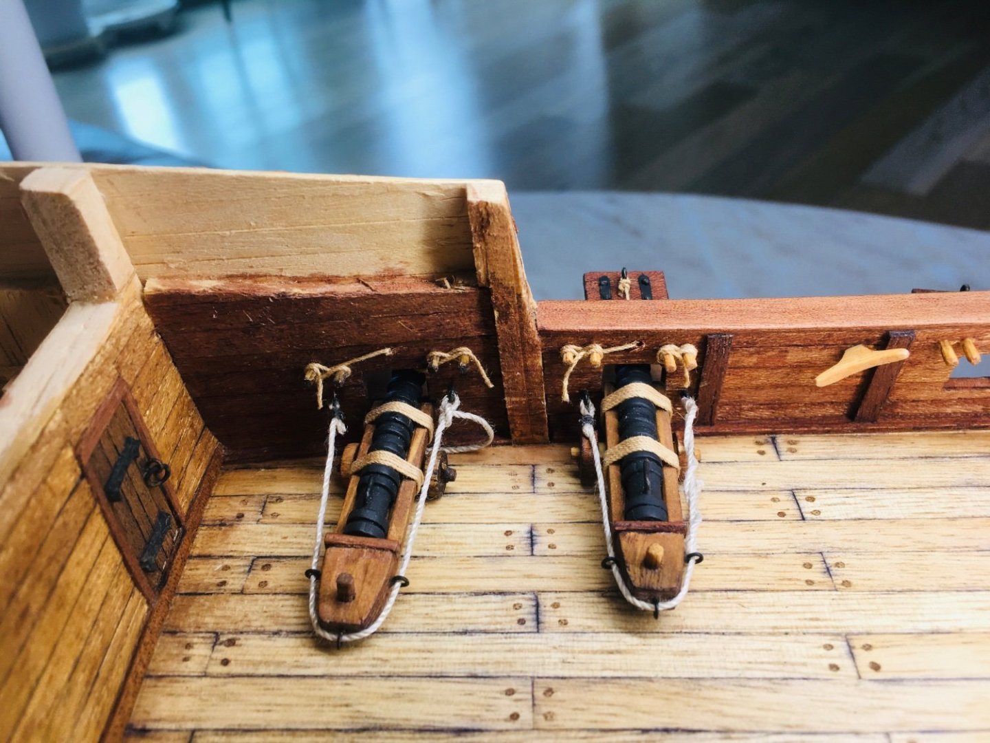
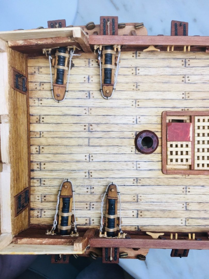
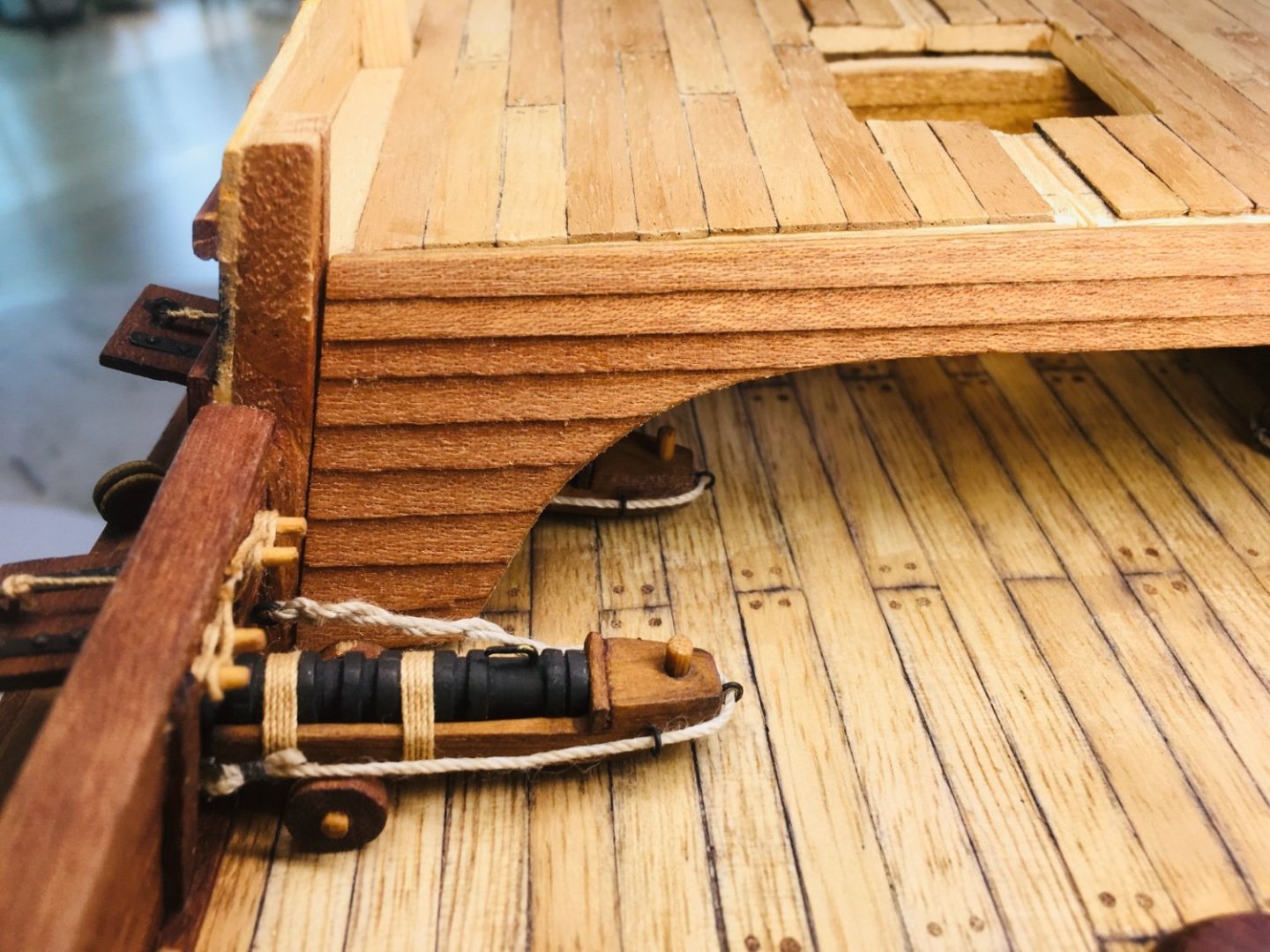
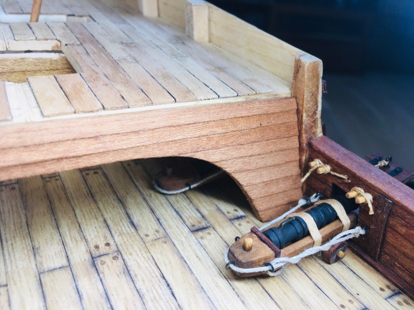
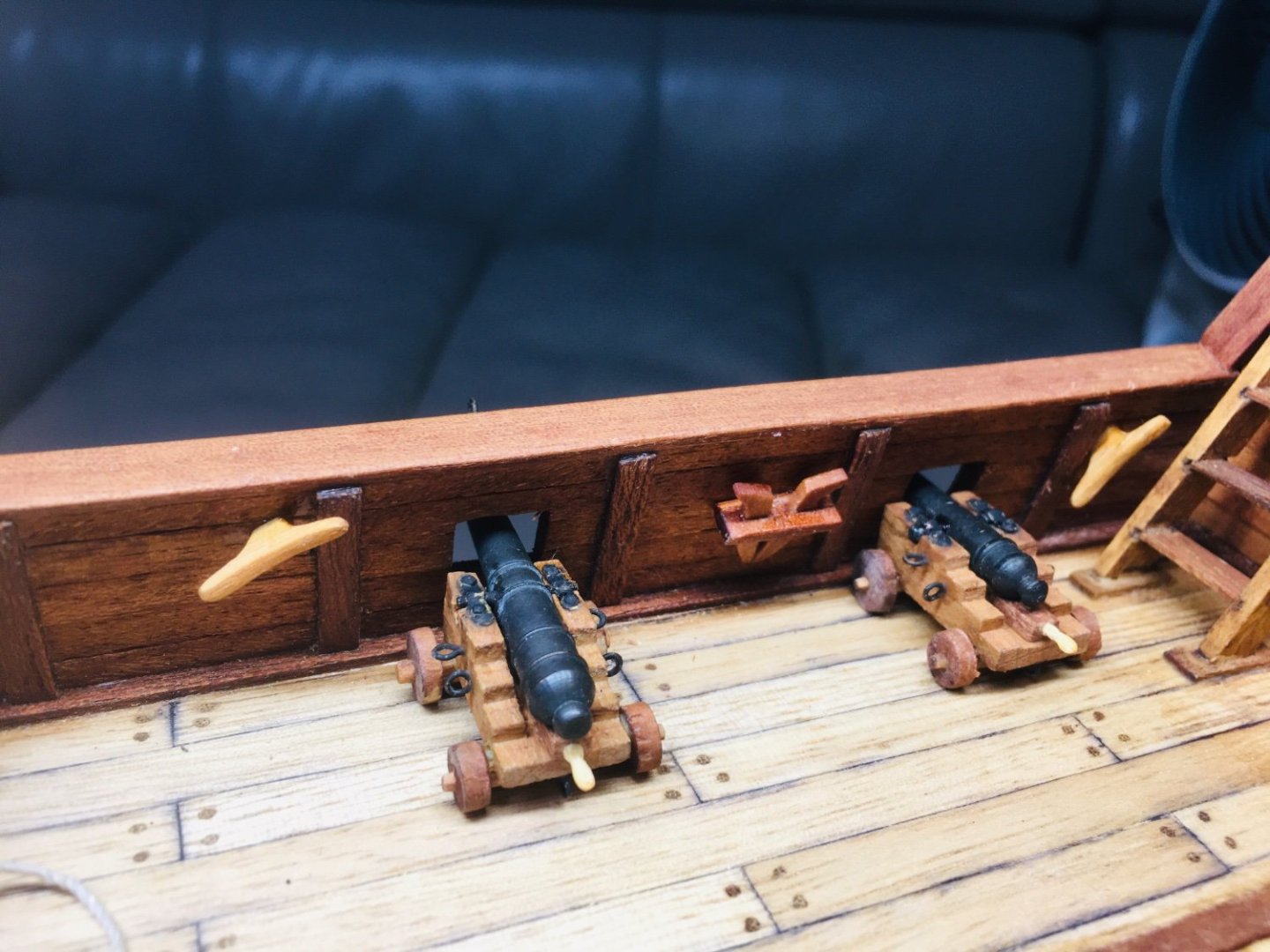
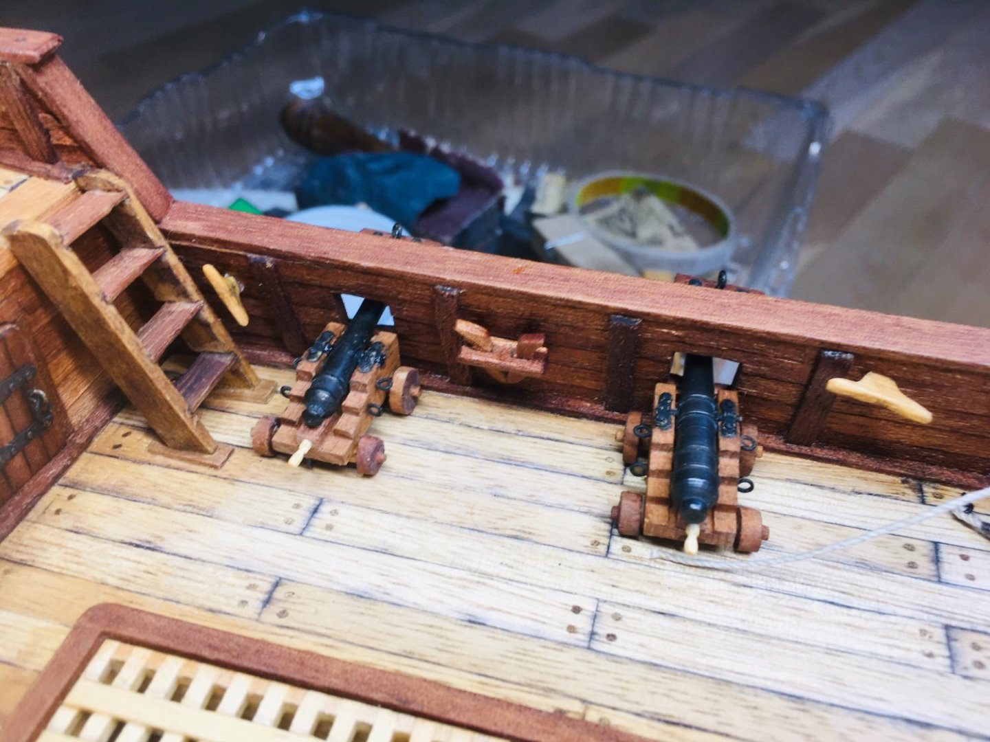
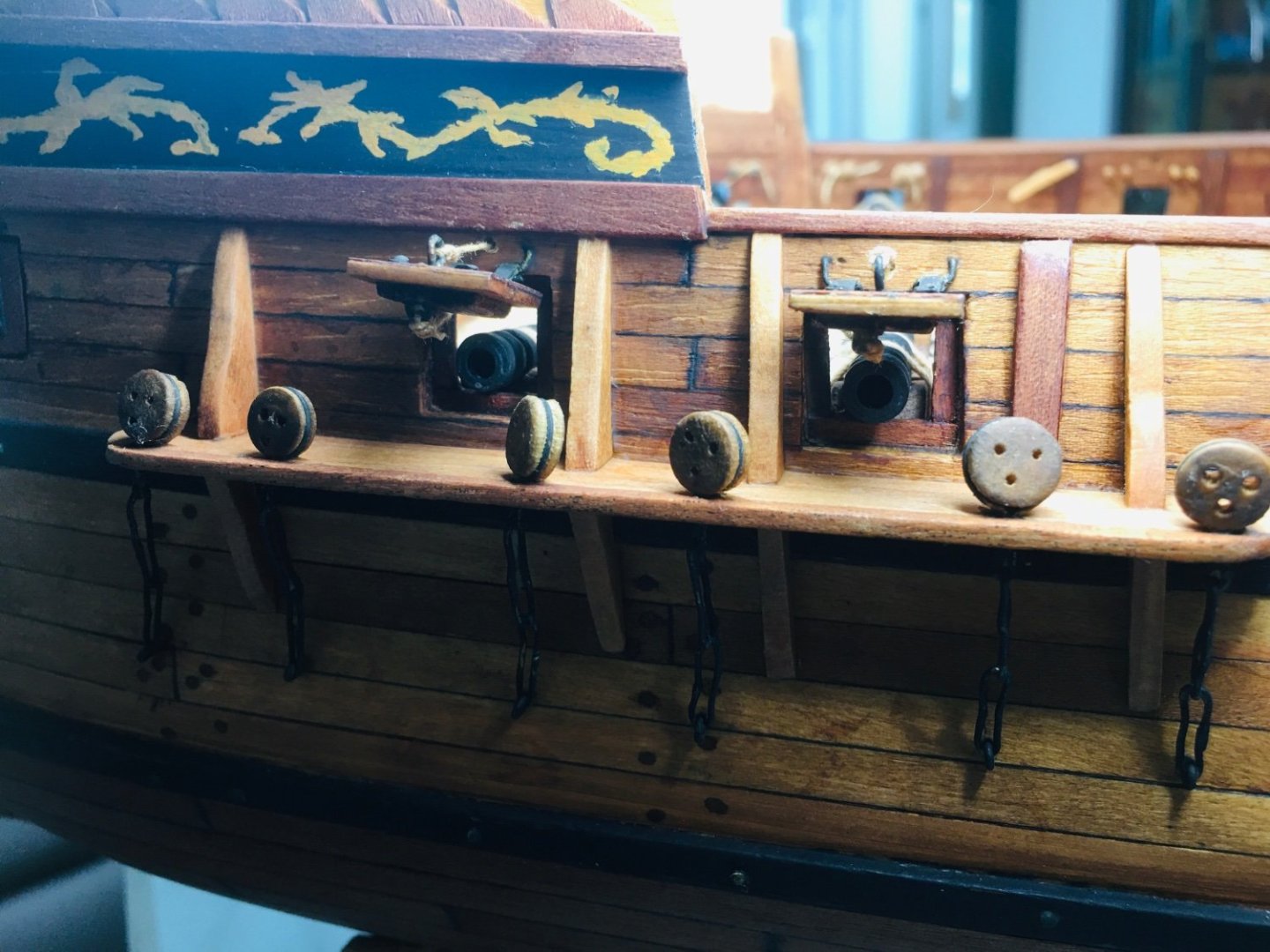
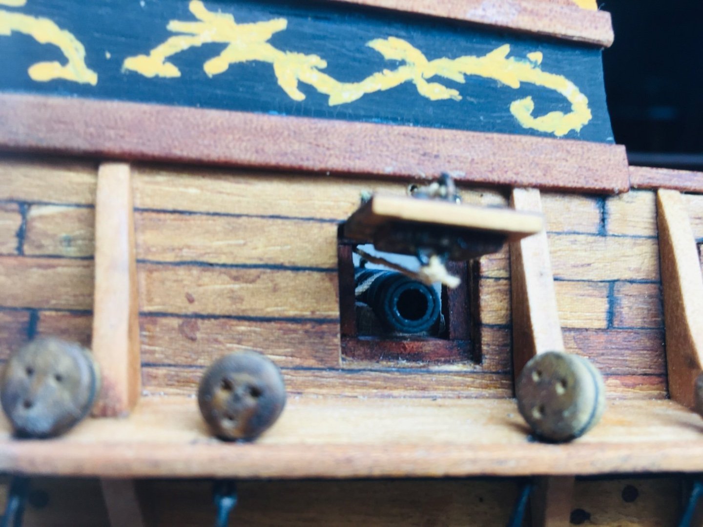
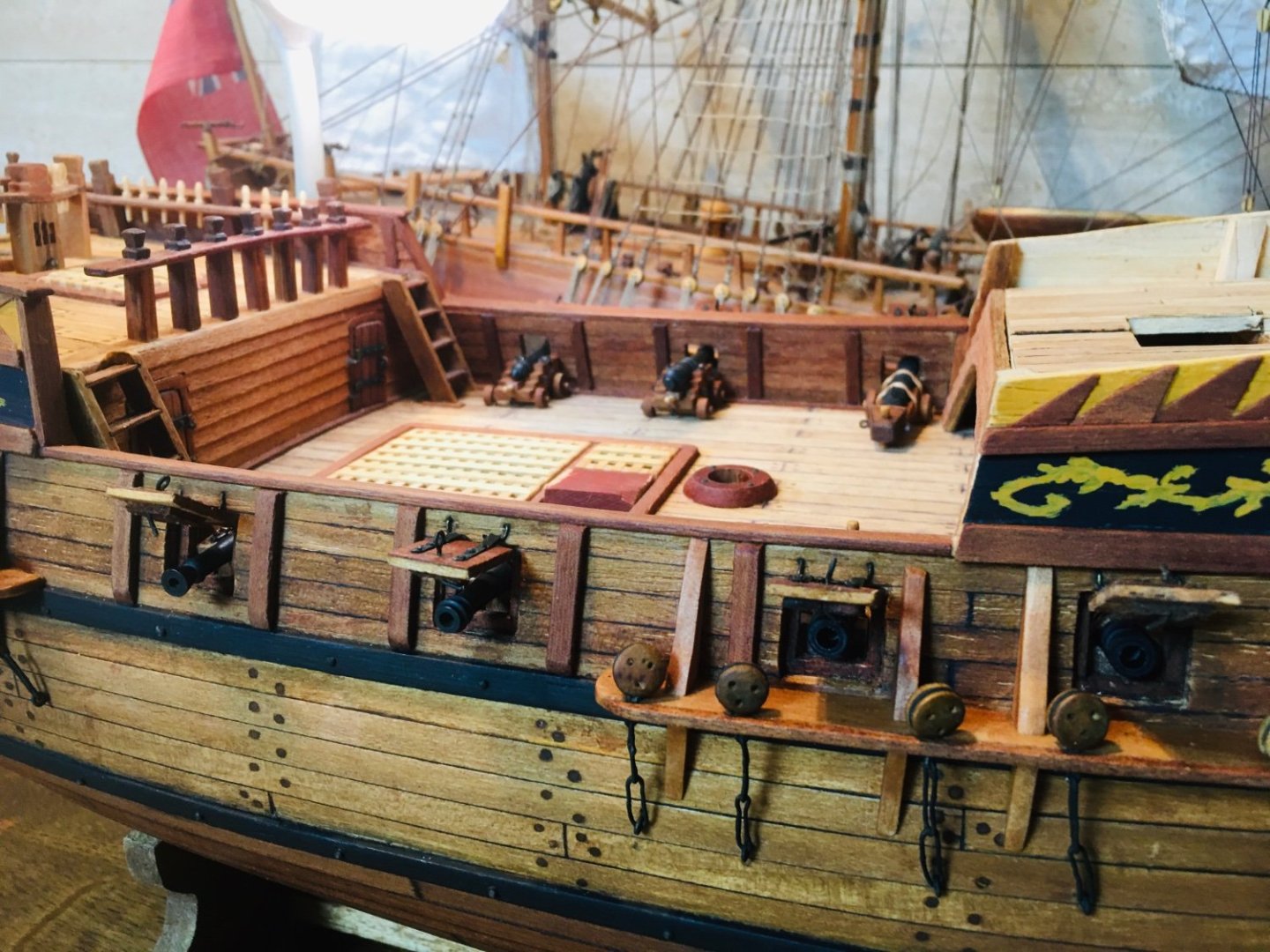
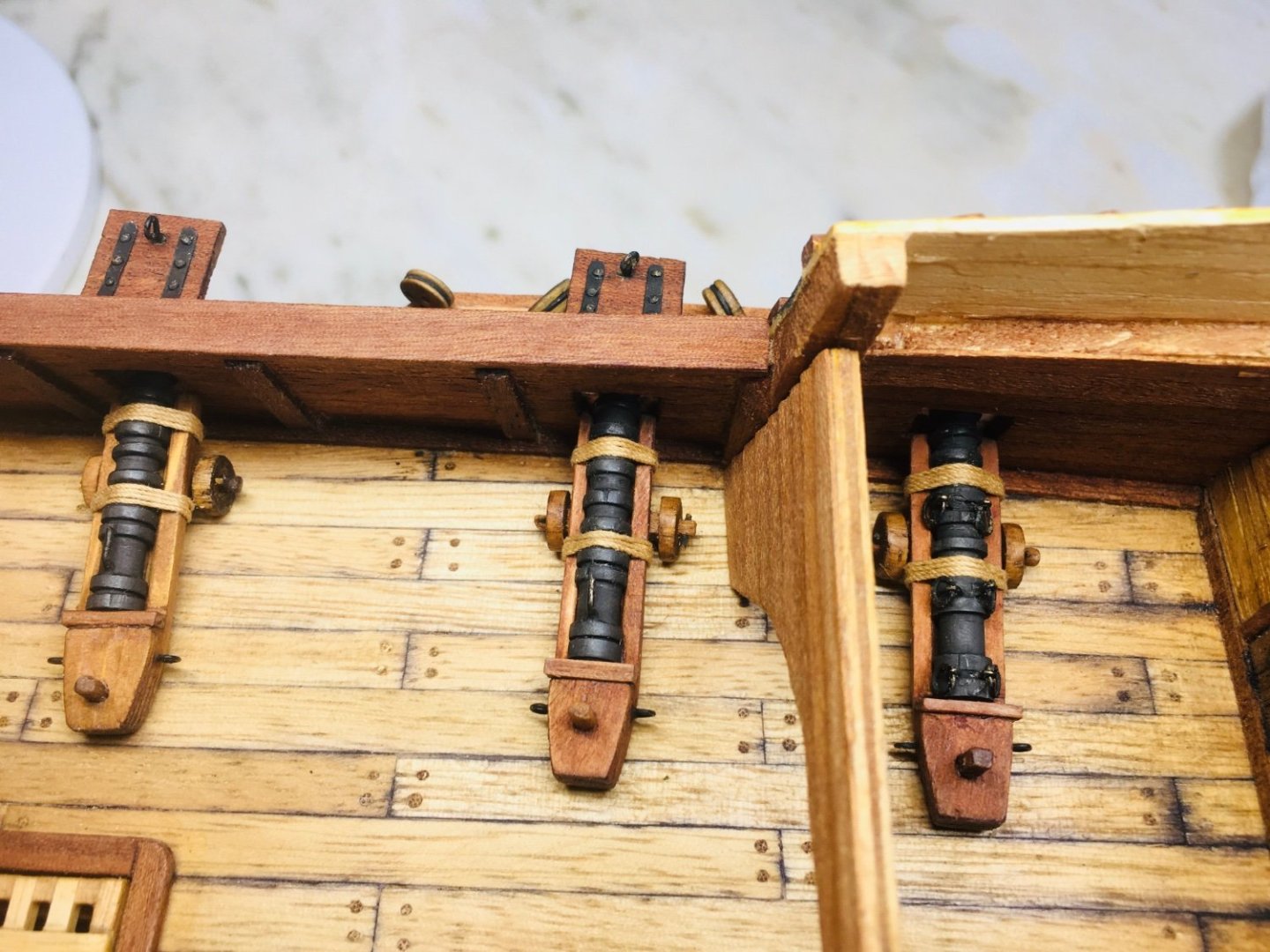
Finalizing the gun port works~ I decided to install the wrought iron guns for now as these will be difficult to install when the quarterdeck work begins. So, the demi-culverins will be installed at a later stage.

-
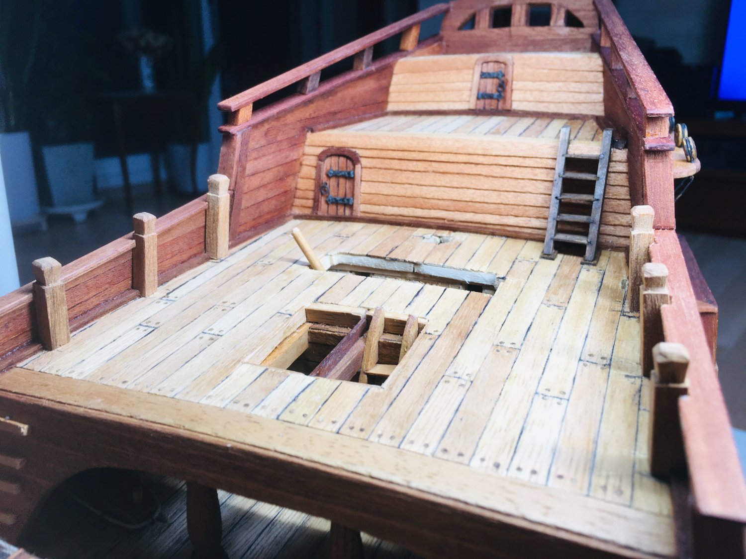
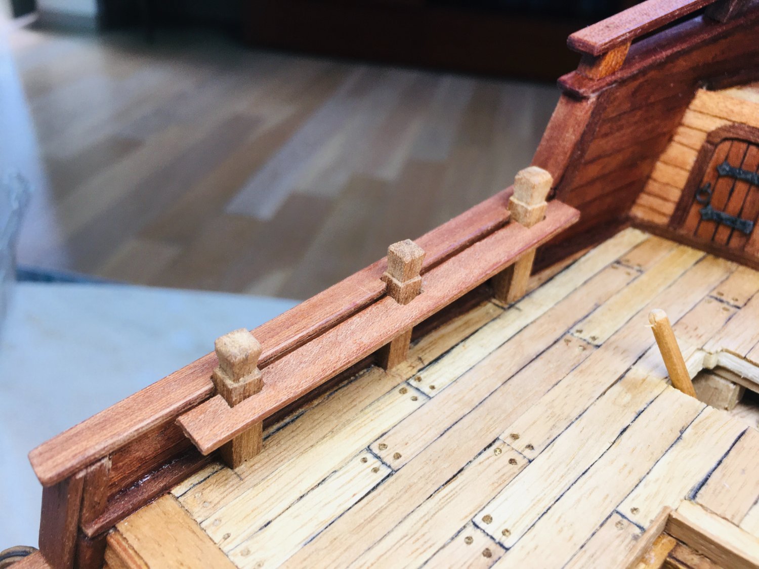
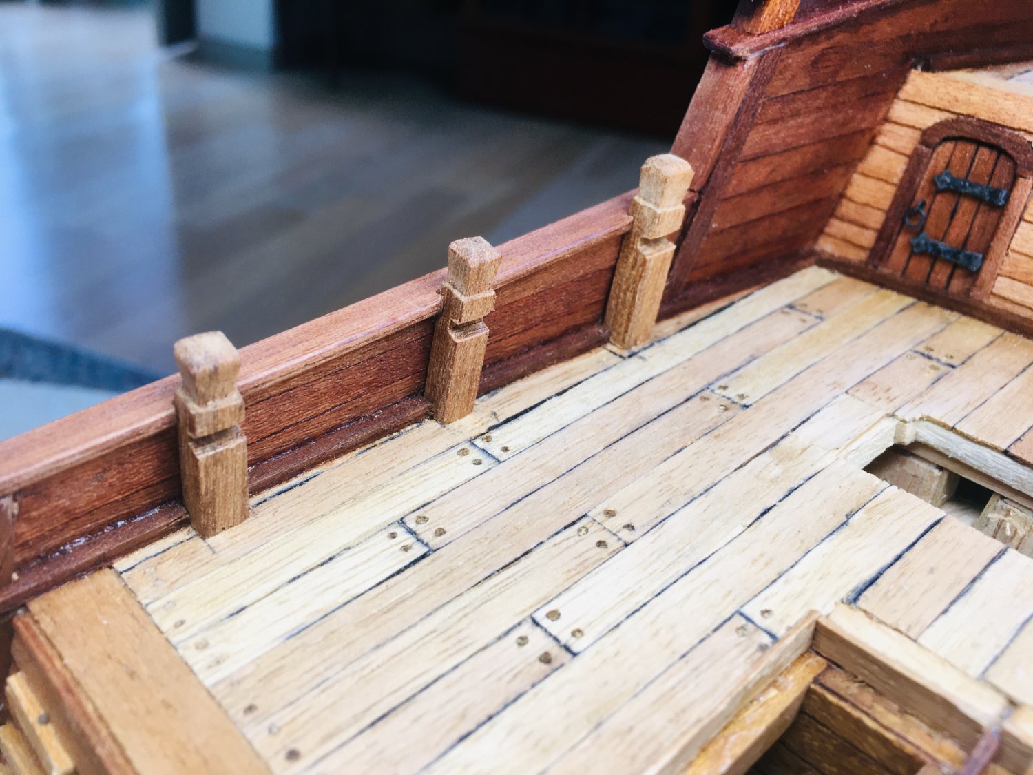
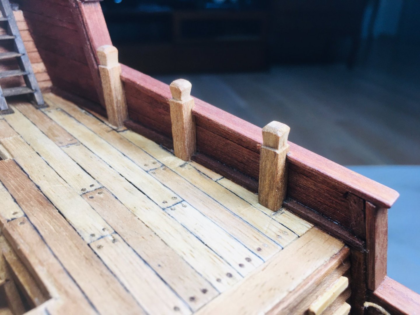
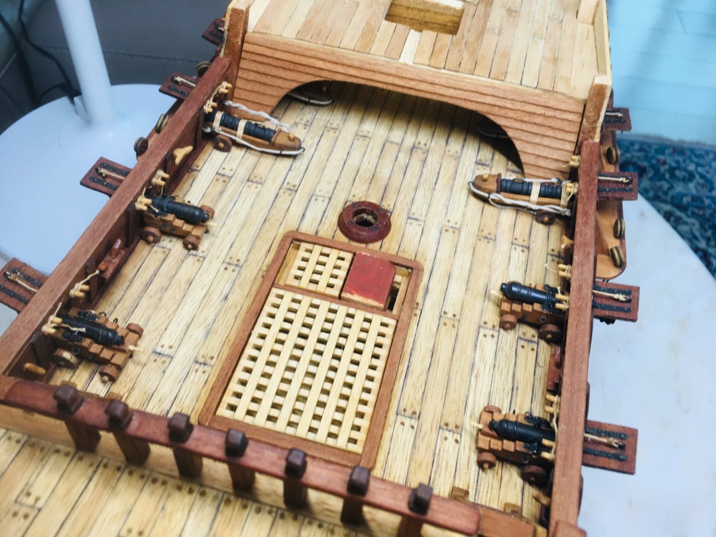
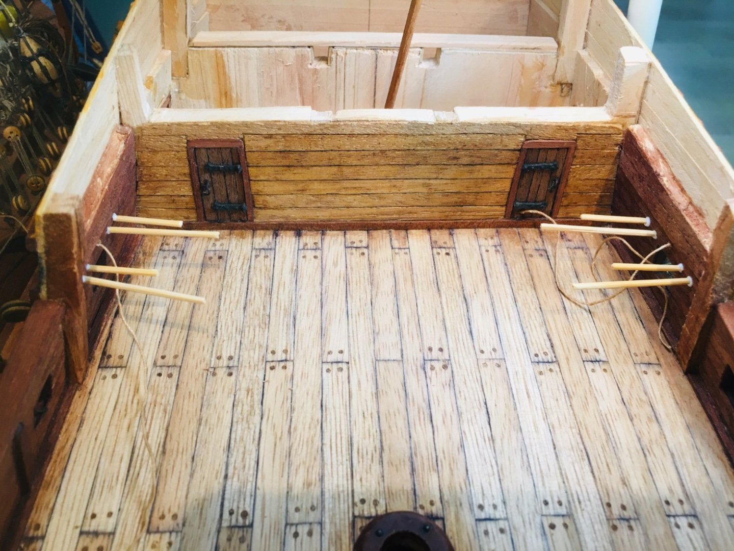
I originally planned to put 2 kevels and one cleat on each side, but unfortunately there were not enough space for 2 kevels if later rigging and etc are considered - so, 2 cleats and 1 kevel on each side for GH1. I will definitely plan better from GH2 onwards so that the gun port spacing as well other structures in that area do not impede 2 kevel and 1 (or 2) cleats installment. I realized after glueing them that the cleats seem a bit big (actually, looks like giant cleats!) and probably off the correct scale. I may redo these later on. But, for now, I decided to leave it as is. Structures for gun port rigging are installed for all gun ports. All gun ports that feature open ports are rigged accordingly.

-
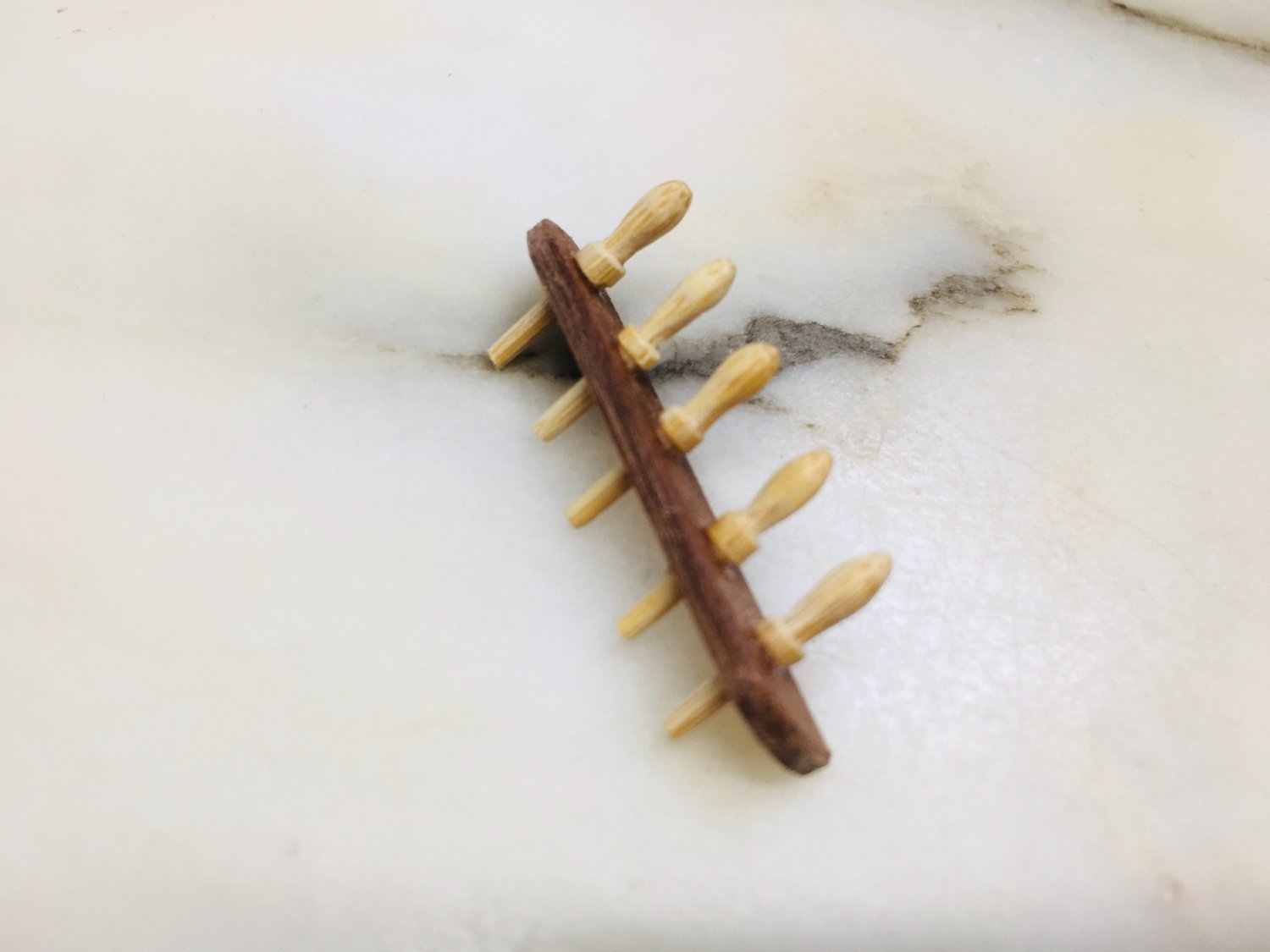
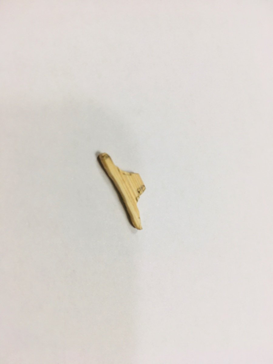
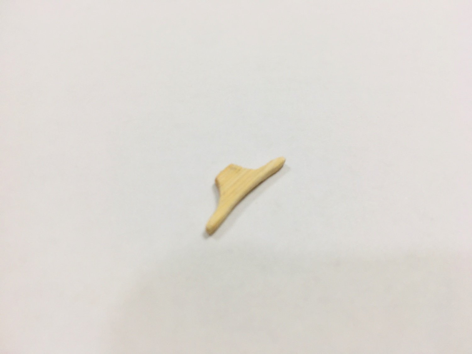
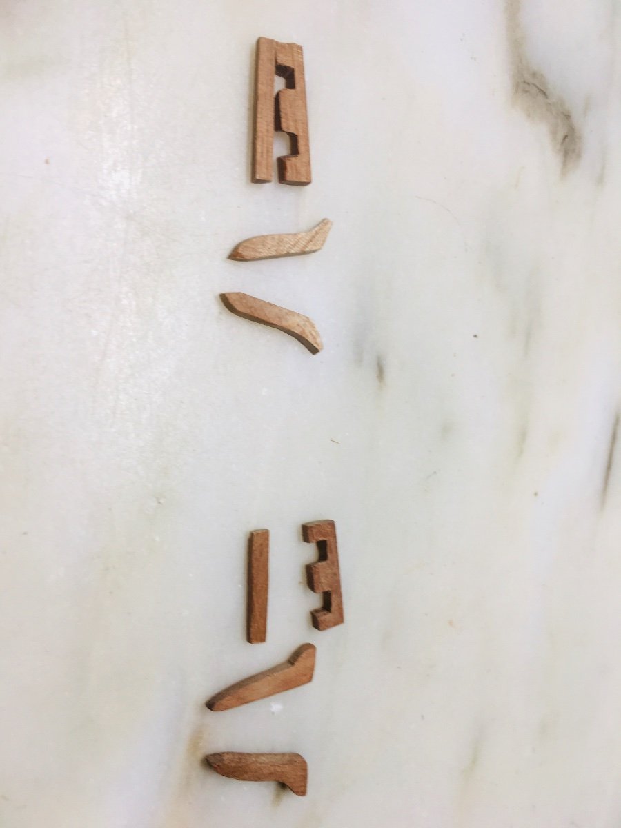
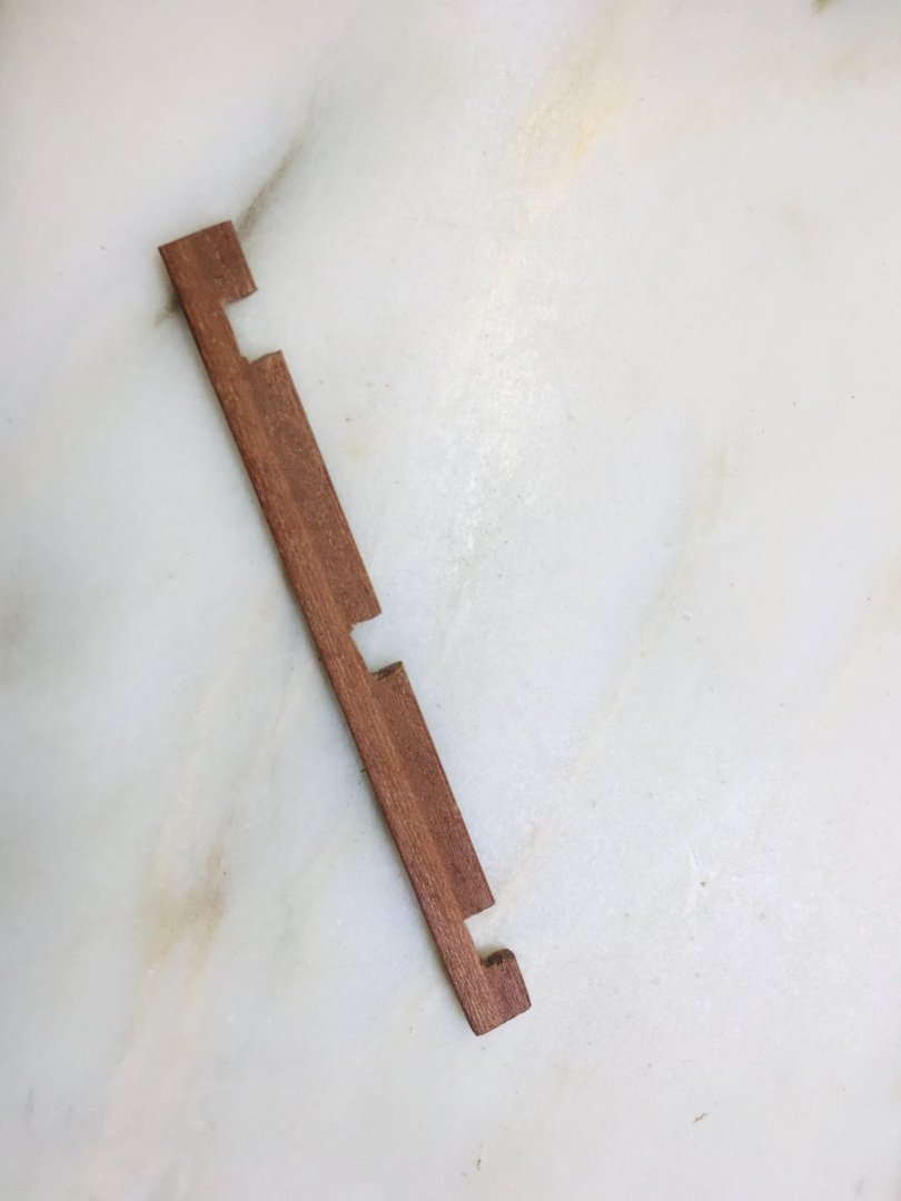
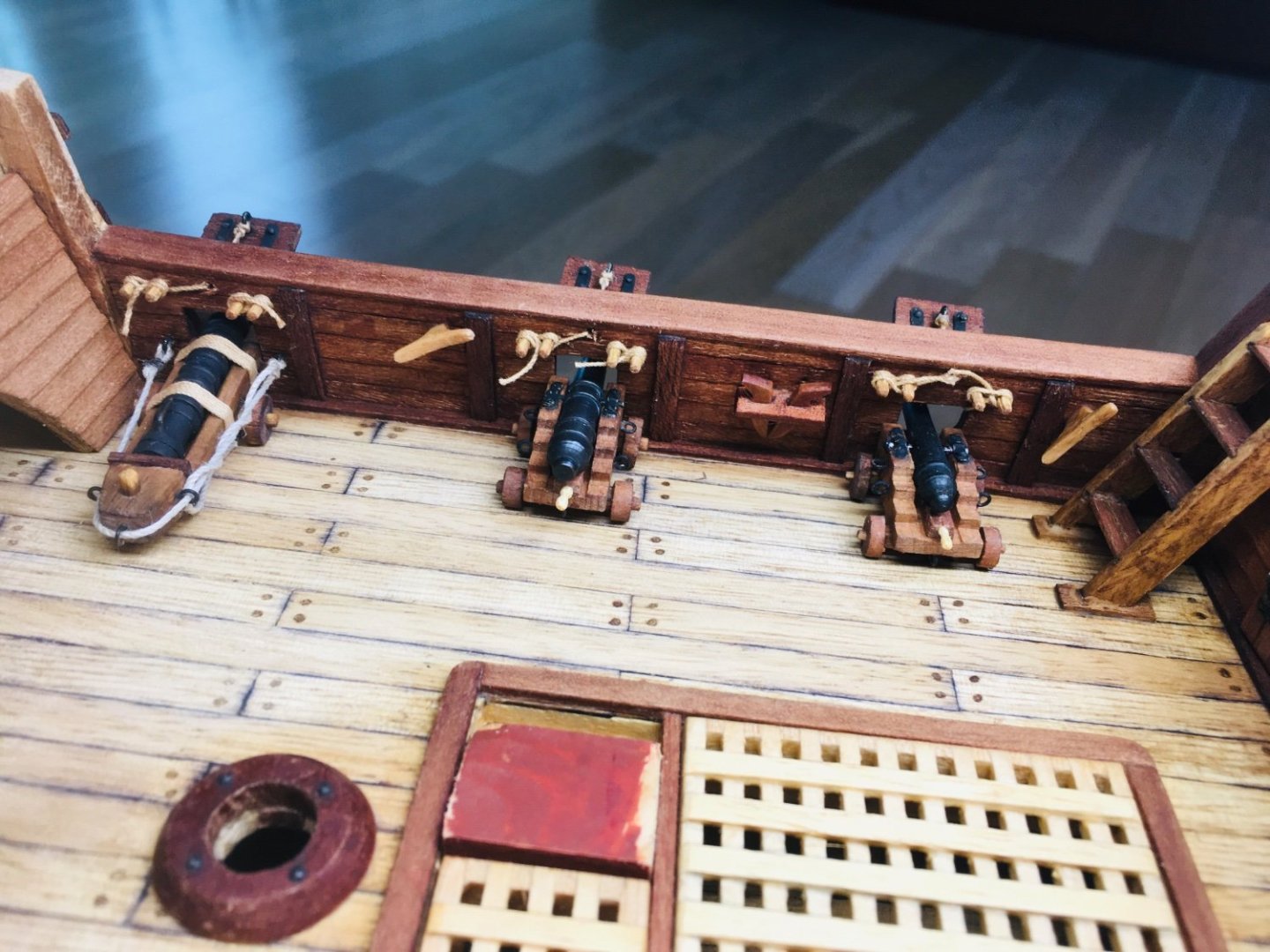
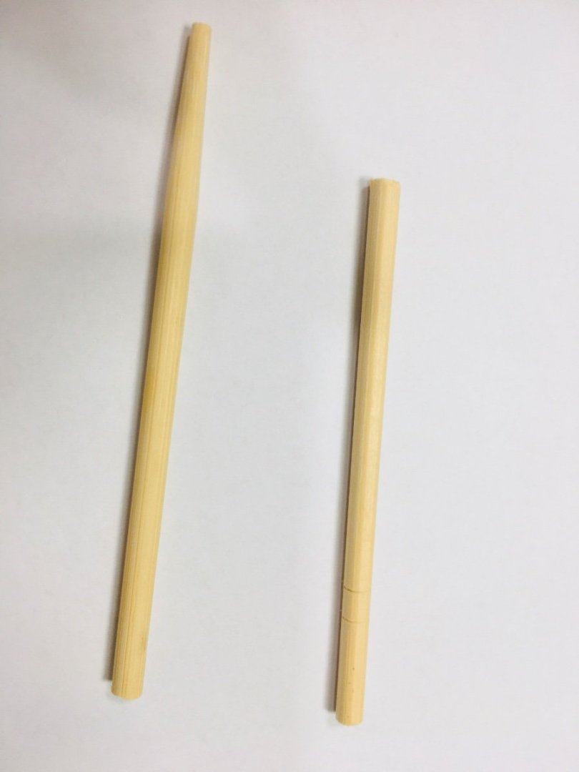
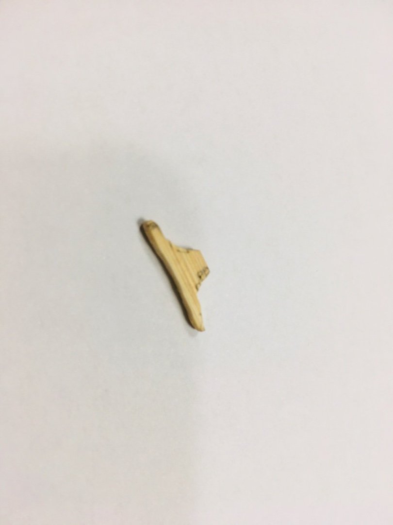
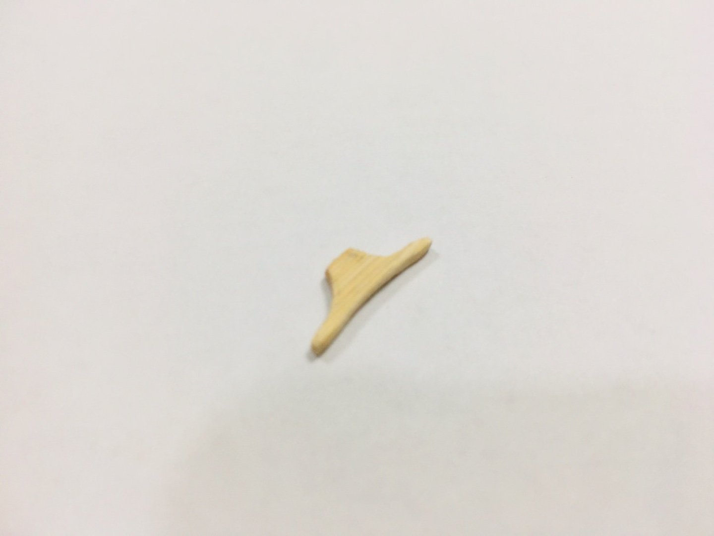
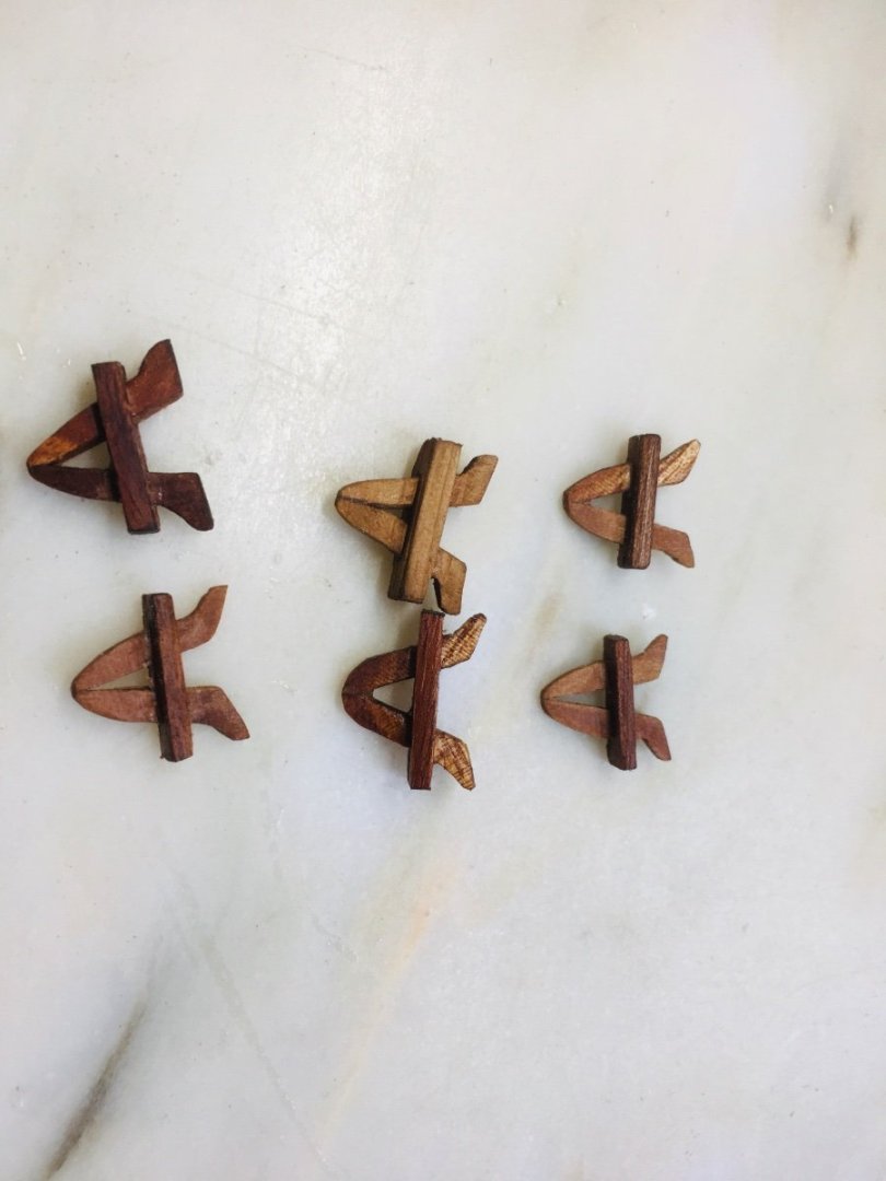
Hello all~ Work continued on cannons, gun port rigging, kevels, cleats and etc. I decided to use both kevels and cleats in midship weather deck area. The cleats were first made from disposable bamboo chopsticks as in the below pictures (I think I am really evolving into ‘master’ or ‘champion’ of chopstick recycling). The end result is quite satisfactory - looks good and quite sturdy. For kevels, I used ordinary(?) hard wood in the most simplistic style.


-
Thanks very much for your kind comment, Robert!
-
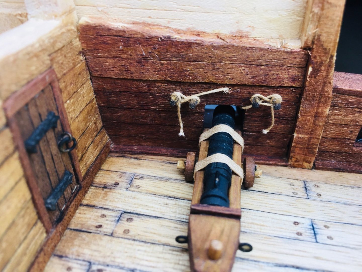
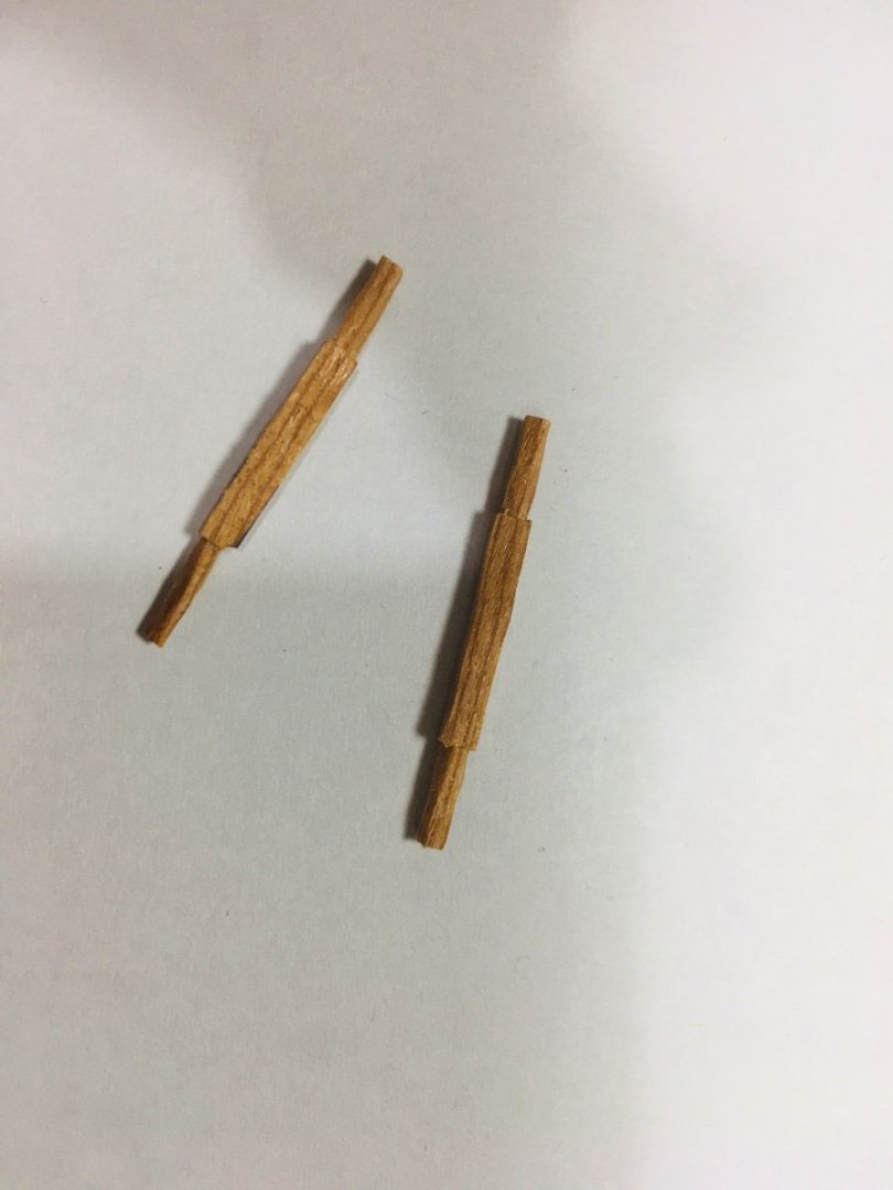
I decided to try out a simple method for rigging the cannon doors - 2 short tooth pick on each side of the door top to handle the outer and inner ropes that are tied to the cannon door. First test rigging of the wrought iron cannon done.


-
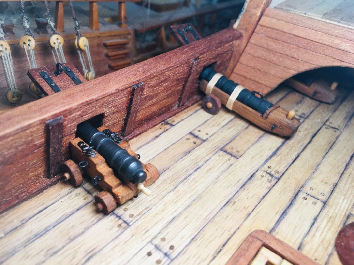
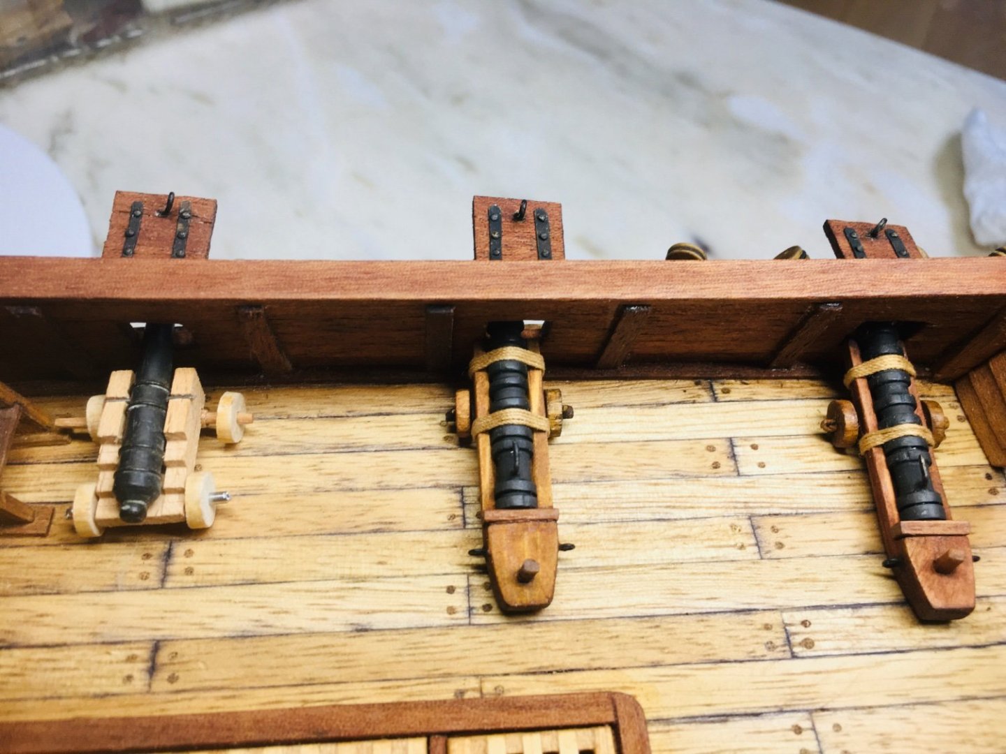
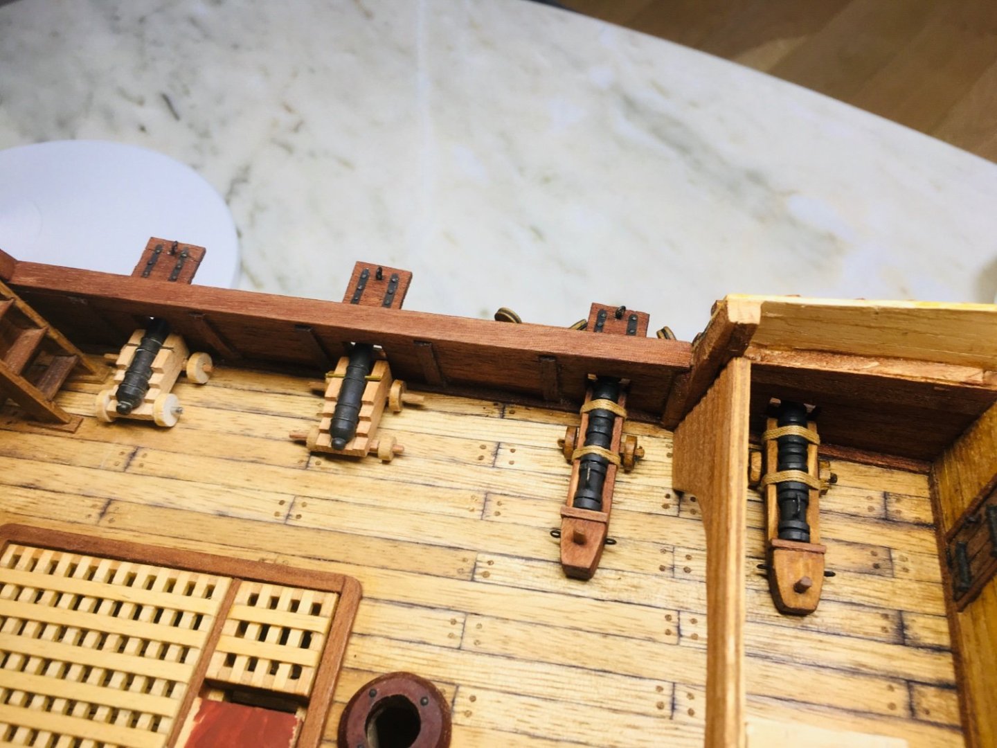
4 demi -culverins done and trying out positions. I decided to put the shorter demi- culverin near the ladder to the forecastle as there seems to be less space here than in the middle of the weather-deck. Cannon door rigging also started in couple of test cases.


-
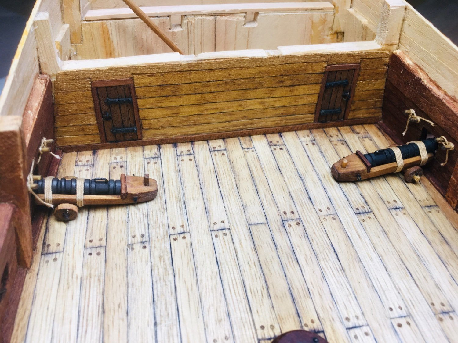
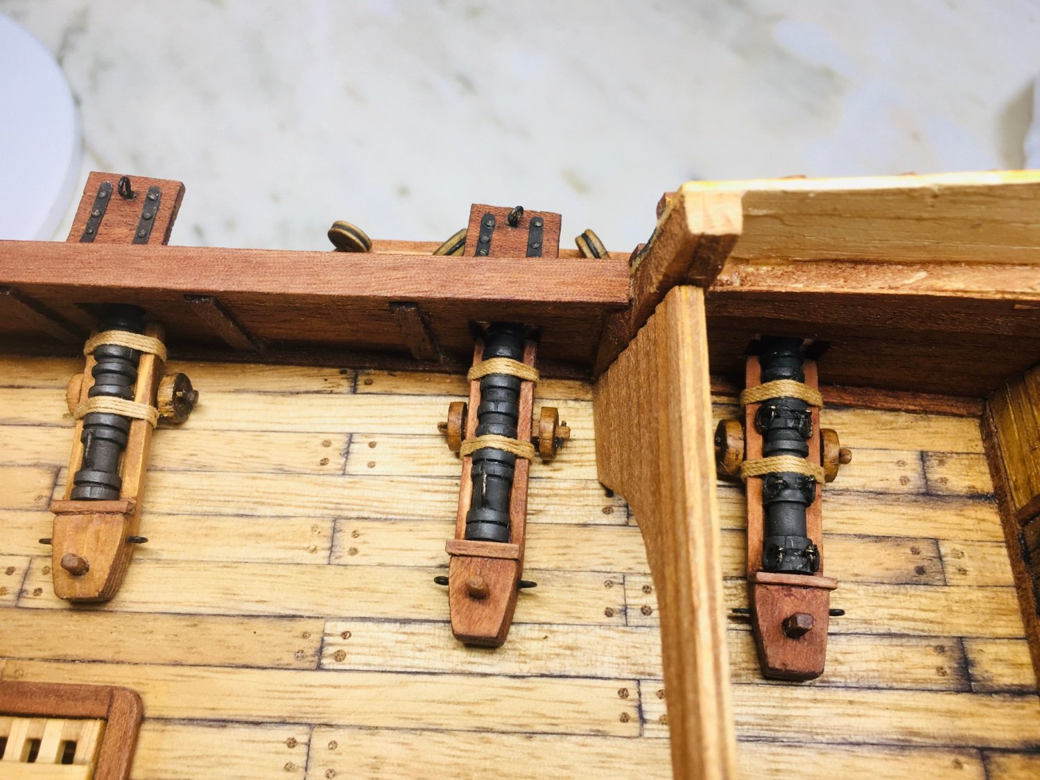
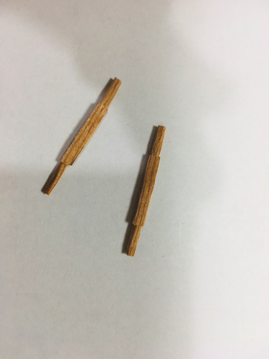
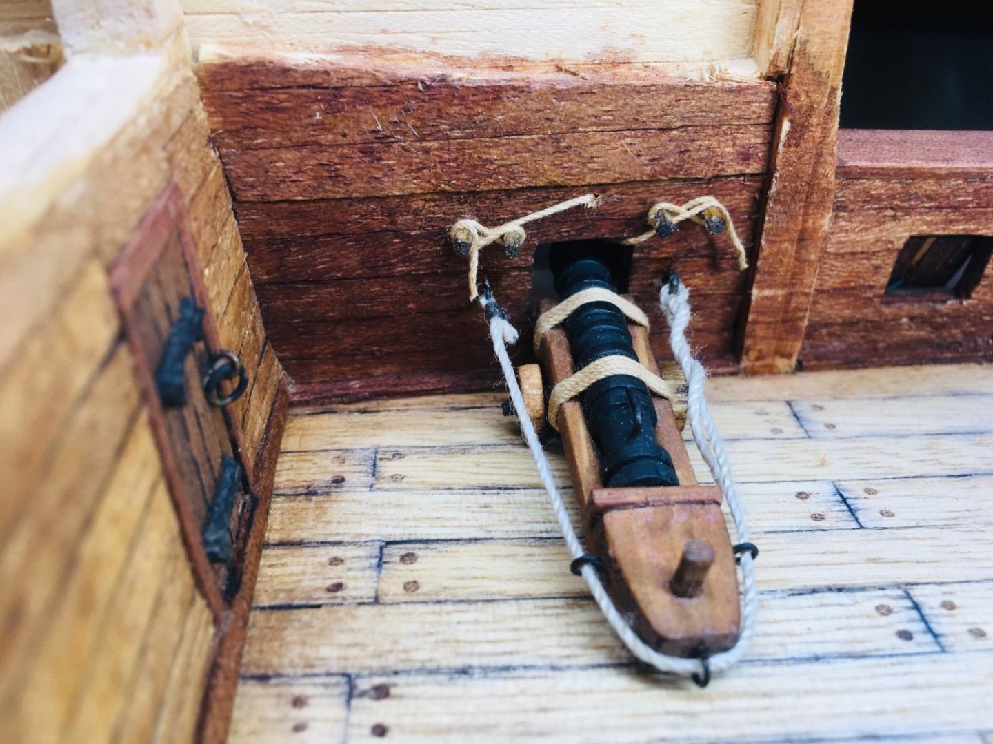
Hello shipmates~ The work on cannons is taking quite a long time! As I am implementing 2 different types of cannons (wrought iron cannons and demi-culverins), the research and prep time are almost double. Nonetheless, it is quite interesting work to deploy different types of cannons. I also plan to try different types of gun positions etc. Anyway, below are the works that have been carried out on the demi-culverins. I used a bit thicker tooth pick to make the handle of the angle adjuster.

-
Hi All~ Just a small update on cannons. I managed to make 1 shorter wrought iron cannon(35 mm) and made finishing touches (varnishing and final mounting) on both the longer (39mm) and shorter guns. It seems that even the shorter one has little room to maneuver in the grating area. Therefore, I made preliminary tests using a demi-calverin, which looks more suitable for that specific area.


-
Roter Löwe 1597 by Ondras71
Rock_From_Korea replied to Ondras71's topic in - Build logs for subjects built 1501 - 1750
Absolutely fabulous work, Ondras! -
Hi Patrick~ Thanks very much for your valuable input and fantastic paper, much appreciated!! Also, what a relief to hear that you think the lengths are about right. As per your suggestion, I will probably apply different variations of wrought iron cannons. I may also try out demi-culverins in areas where there are not much room for these wrought iron guns. If I am not mistaken, Mary Rose wreck yielded a mixture of wrought iron cannons and demi-culverins. Thanks again for sharing your insightful opinion!!
-
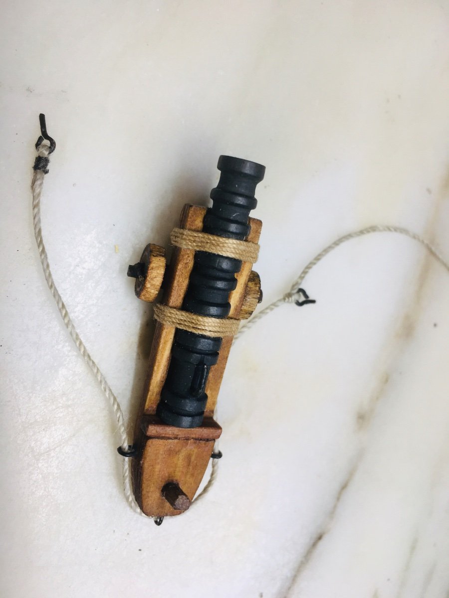
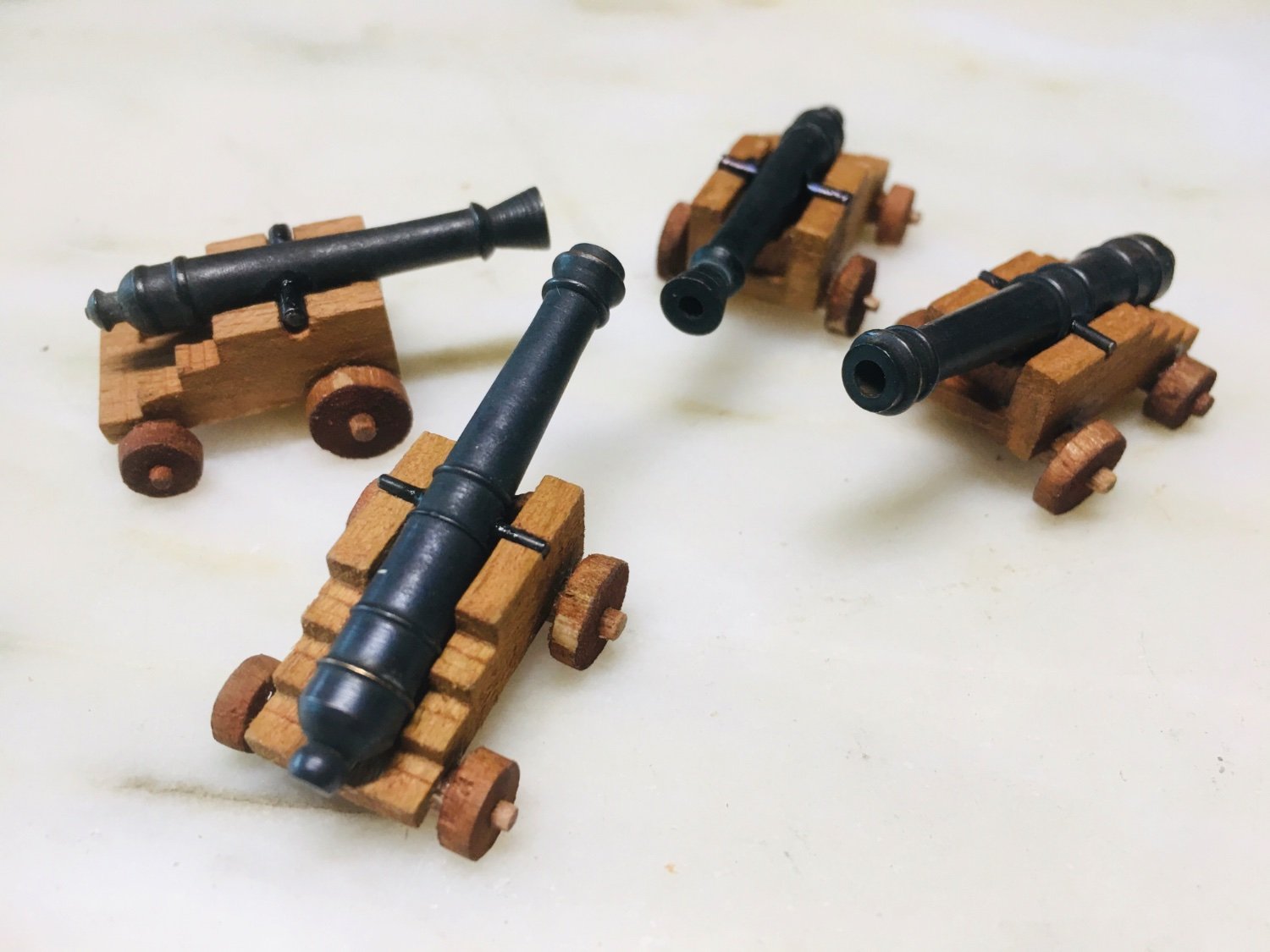
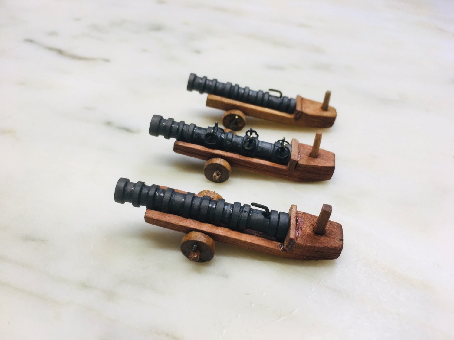
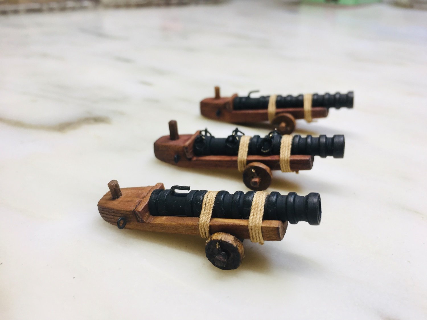
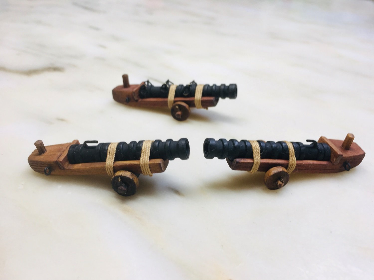
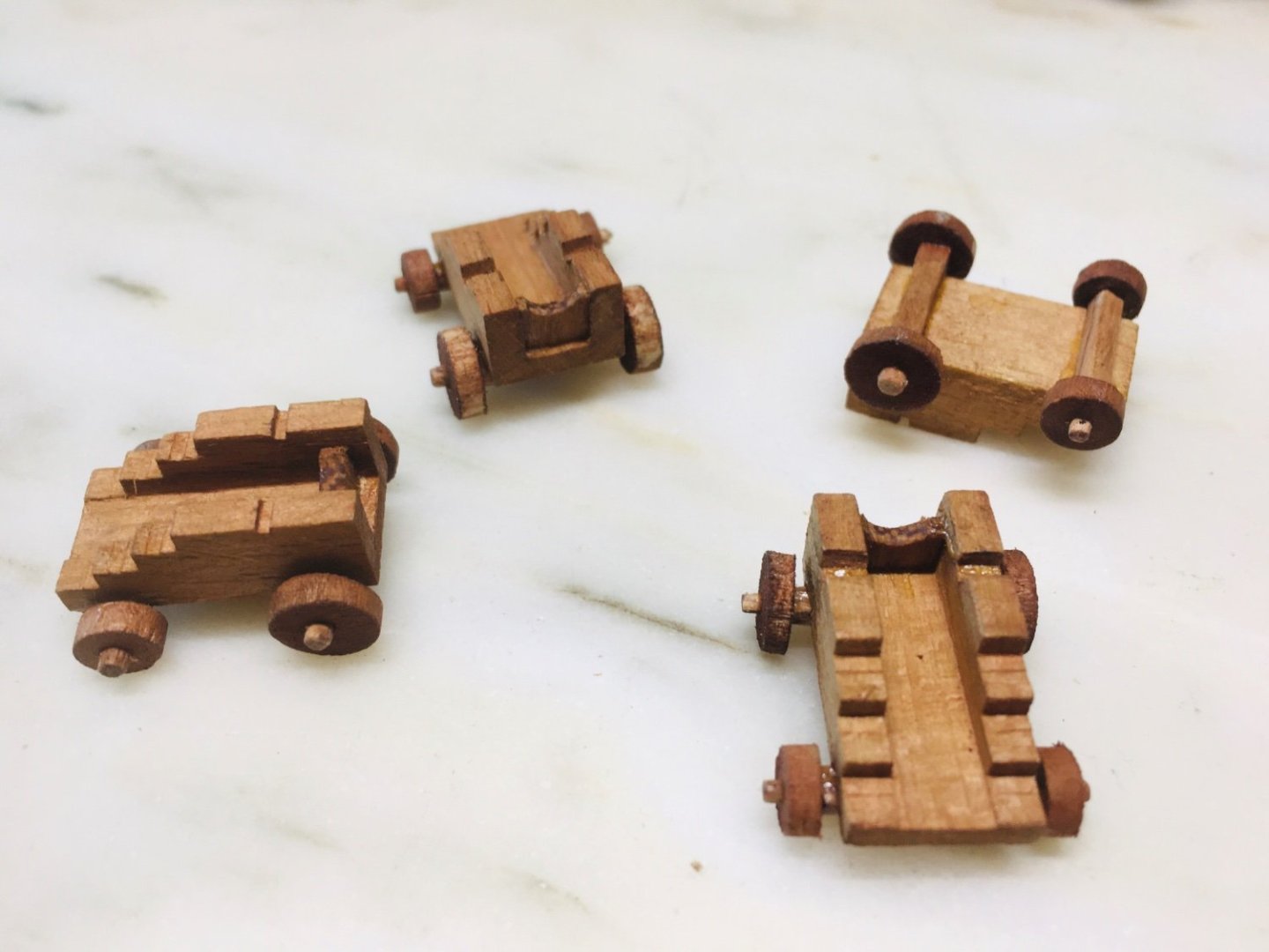
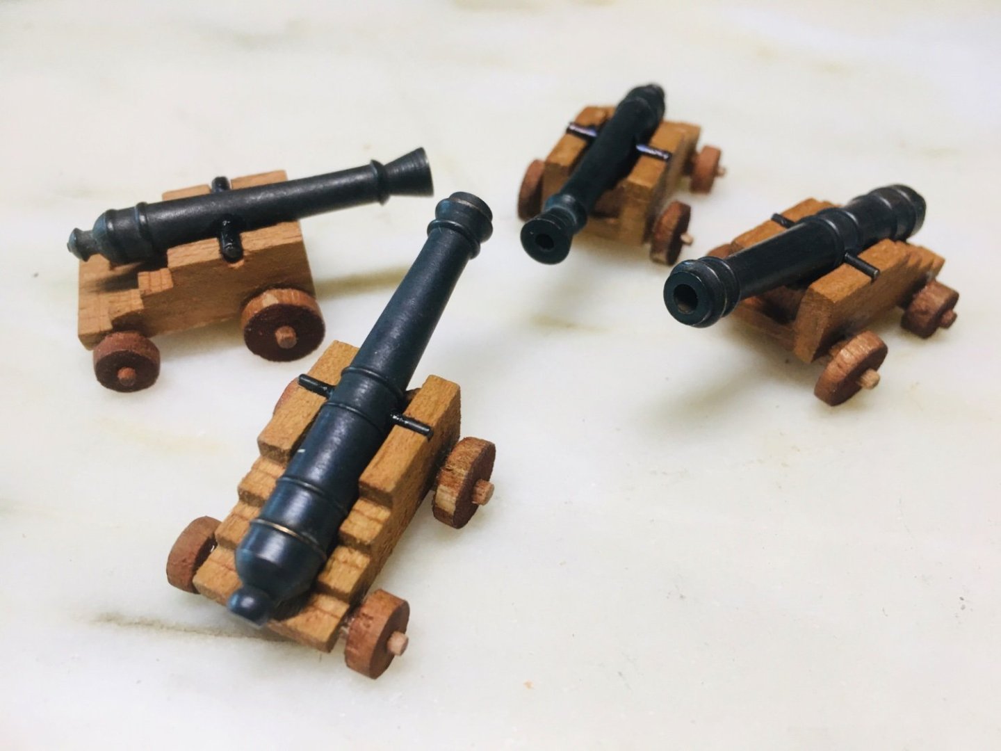
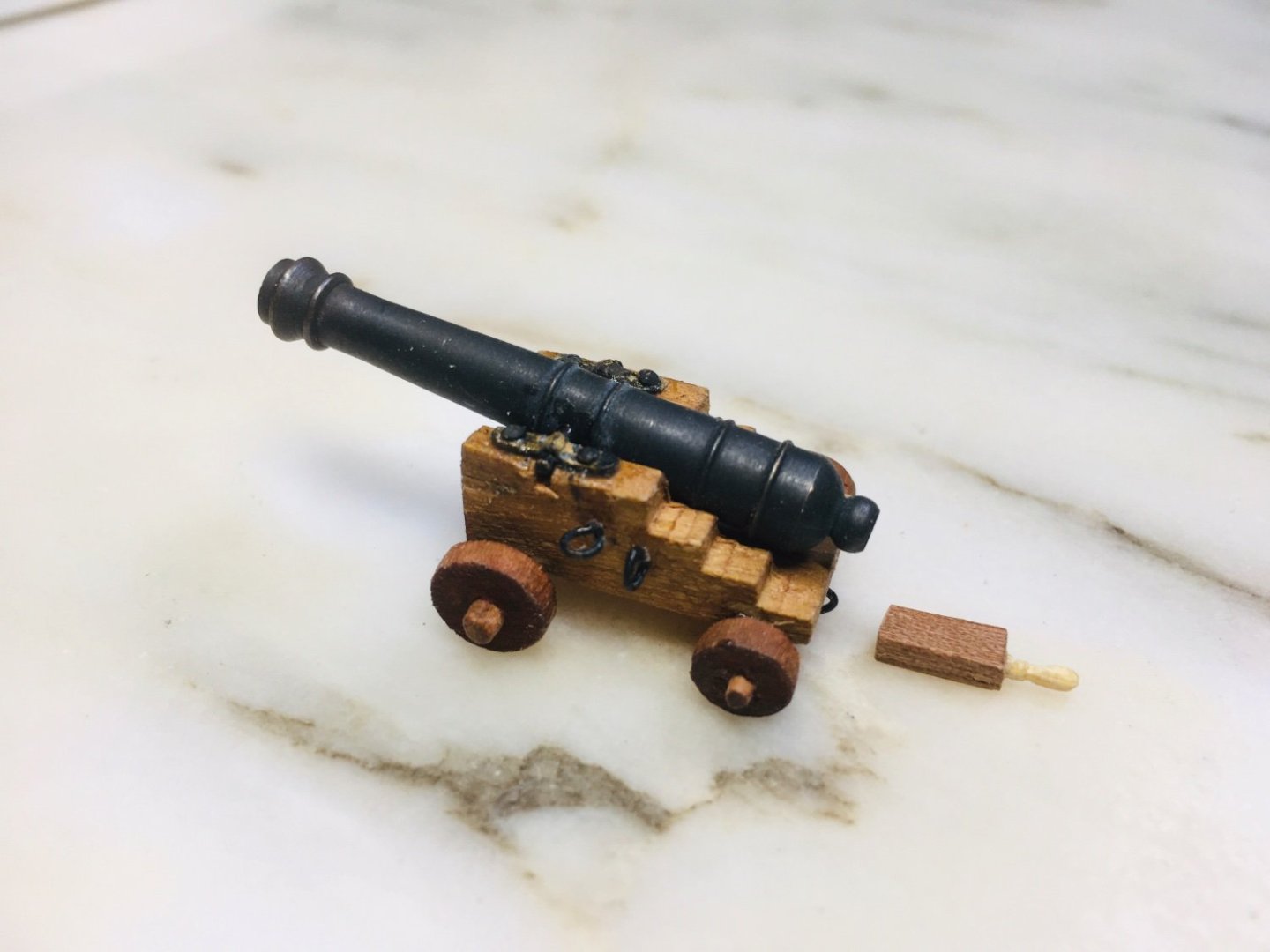
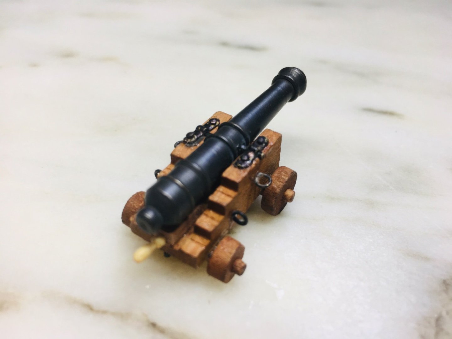
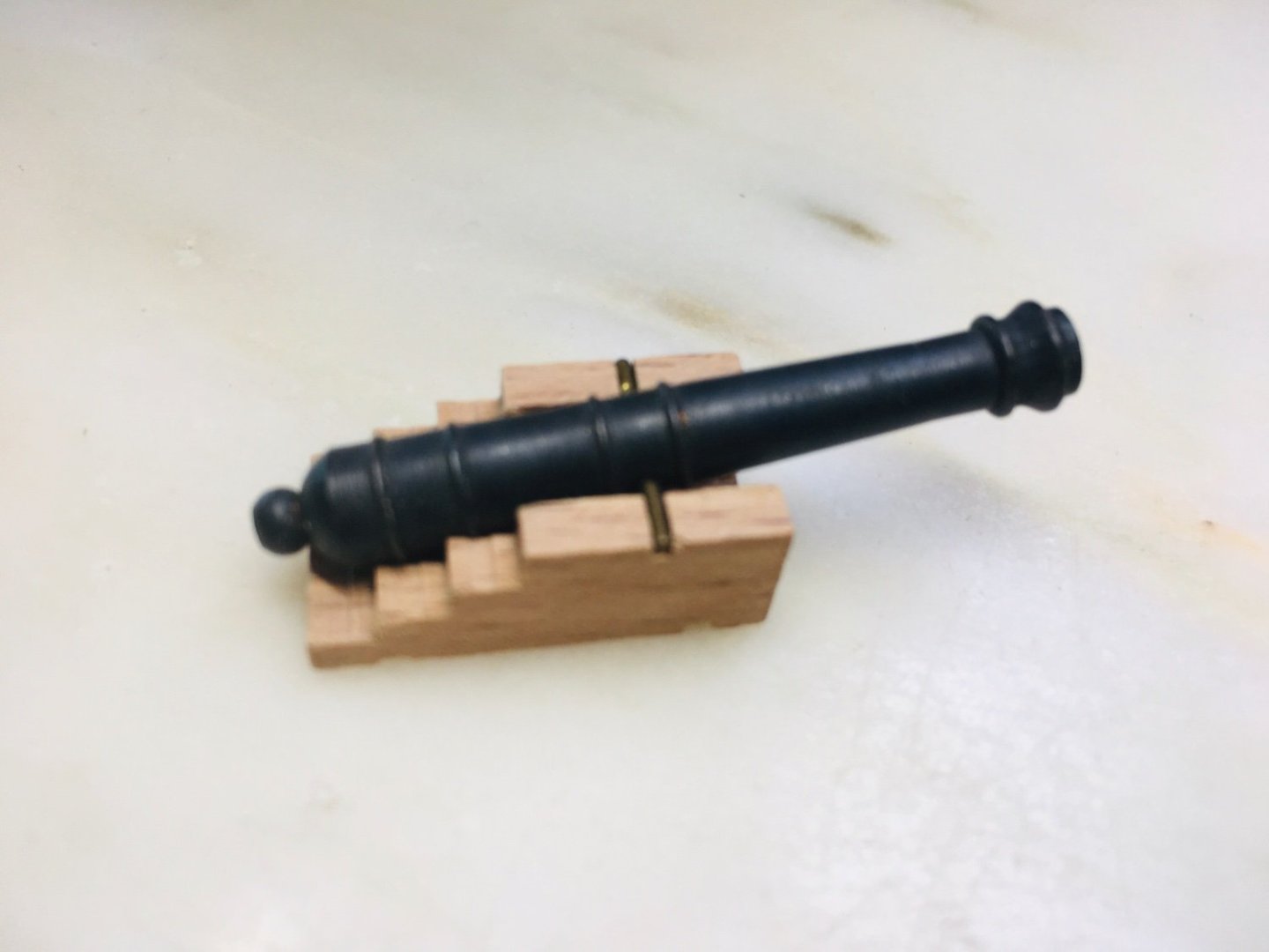
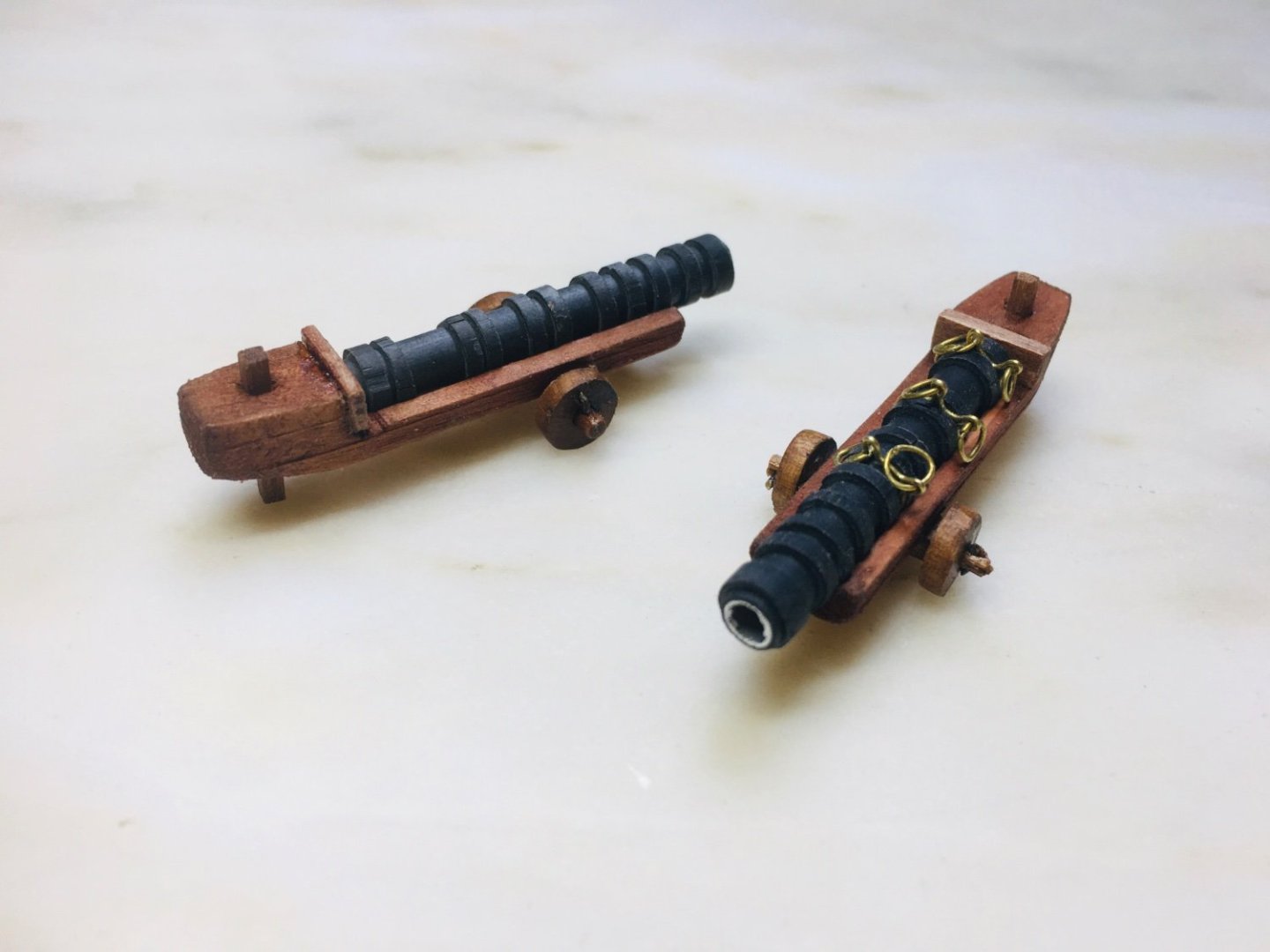
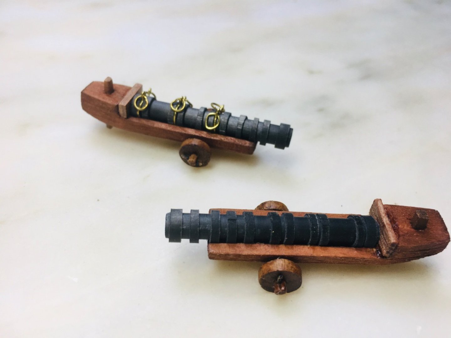
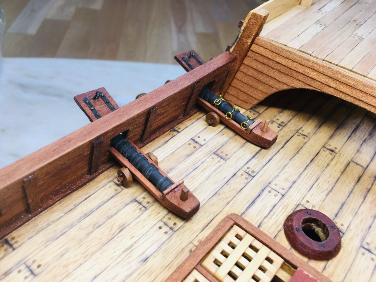
Fairly close now on more or less finishing 2 prototype (39mm long) wrought iron cannons for comparison and testing out on deck. The brass ring handles will be chemically blackened later on. The cannon wagon(?) has been dyed and the angle adjuster has been added at the rear. Satisfied on general look. But, I cannot shake the impression that the overall cannon length is somewhat long. I will need to test the shorter 35mm long barrels in the next work stream.
-
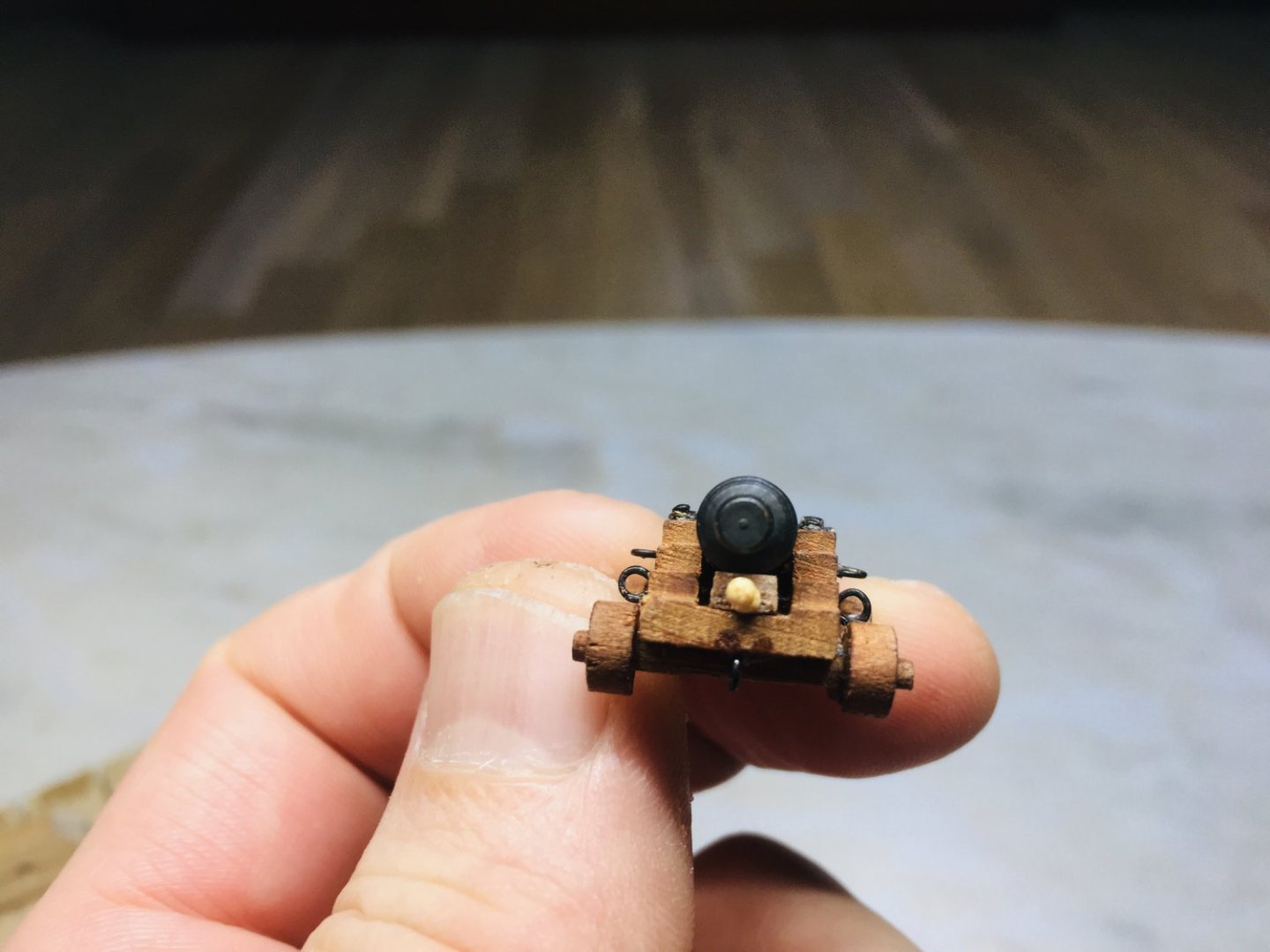
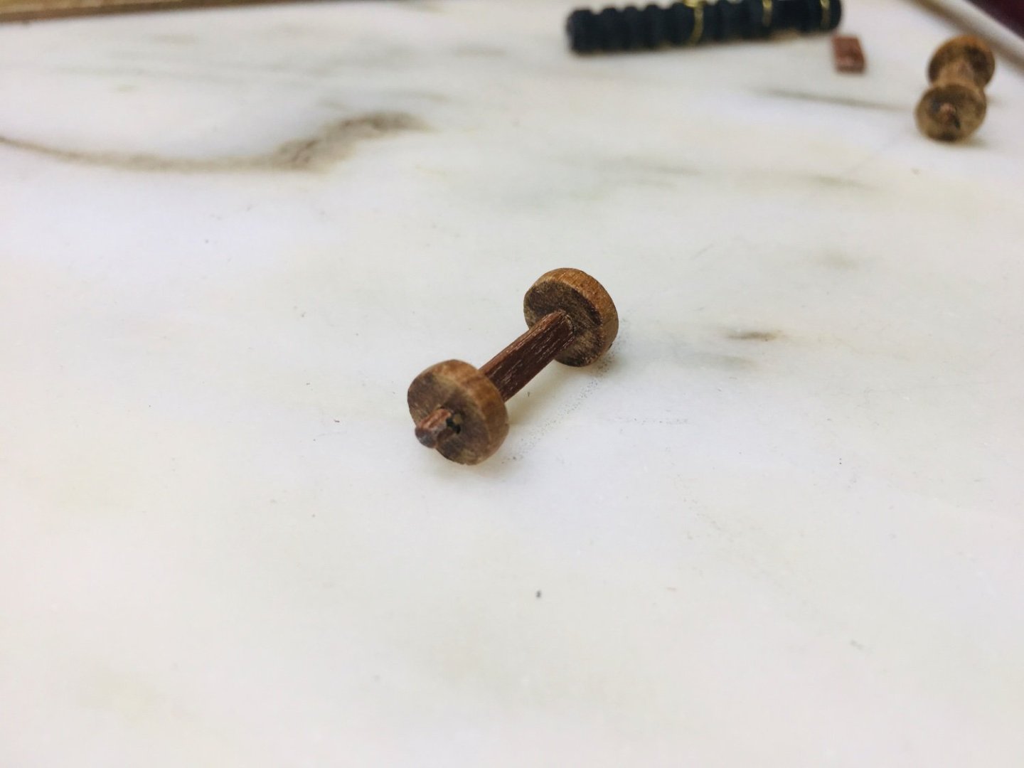
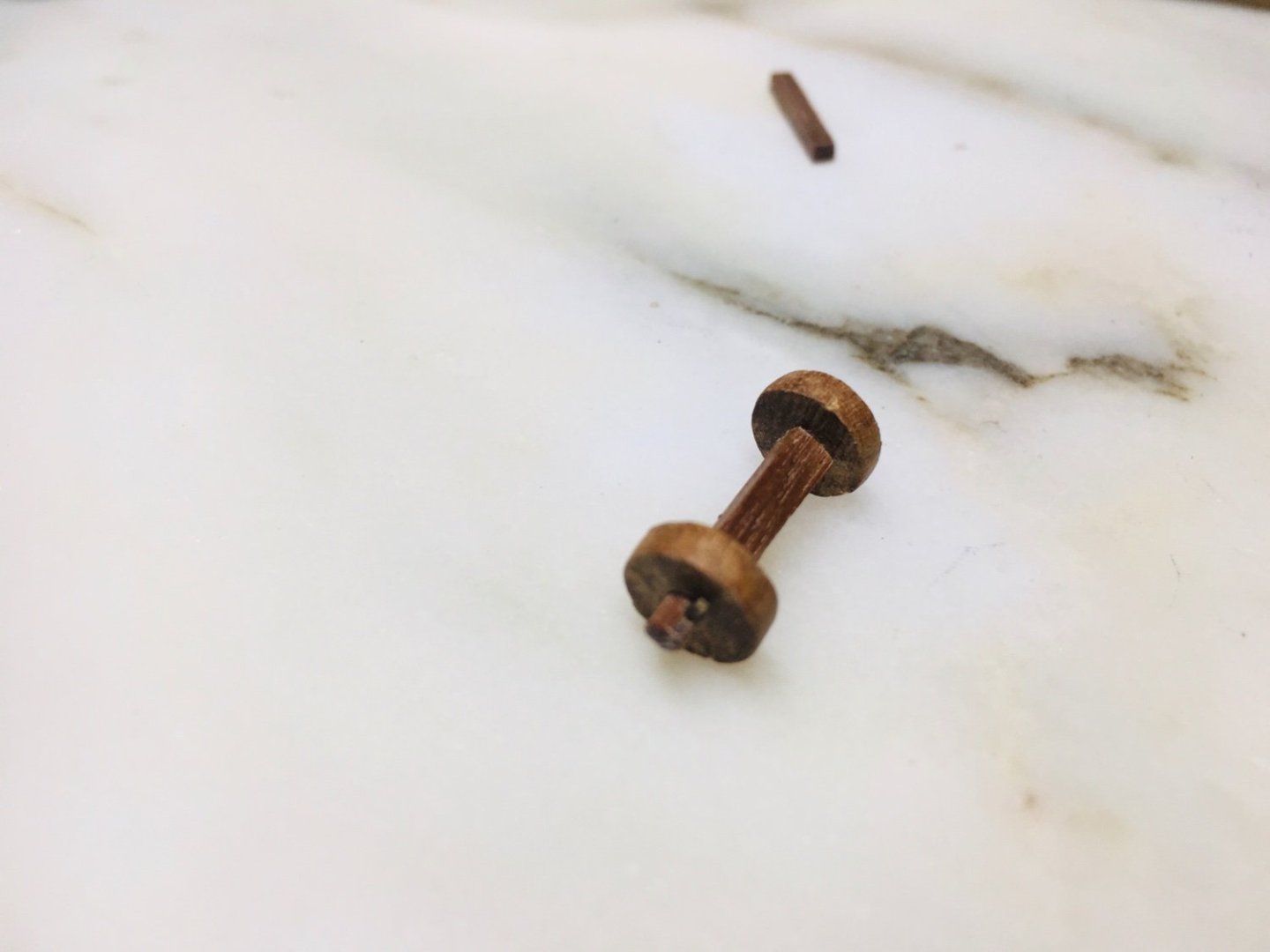
Now moving on to making the wheels. I did not throw away the short (narrower) tips of the decommissioned chopsticks after using them for the forecastle area work. These scrap wood part are coming in handy for the axis of the wheels.


-
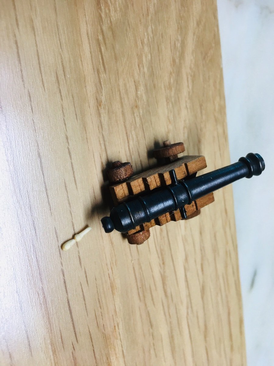
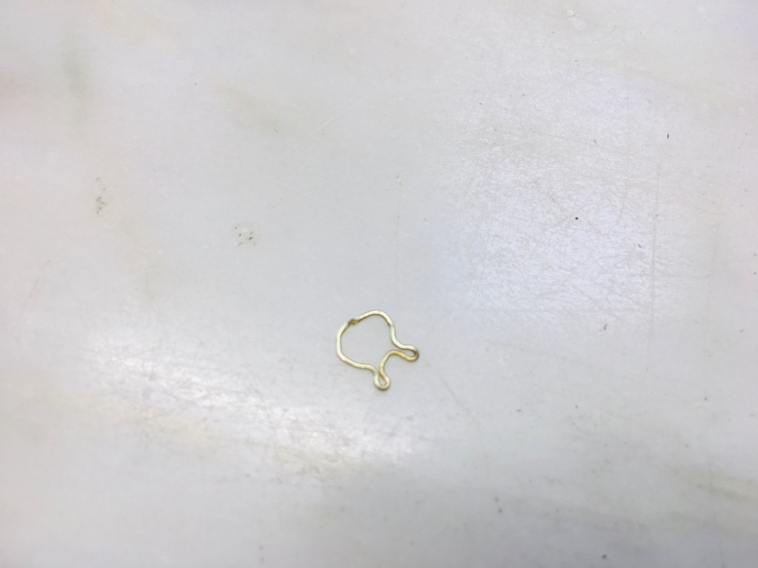
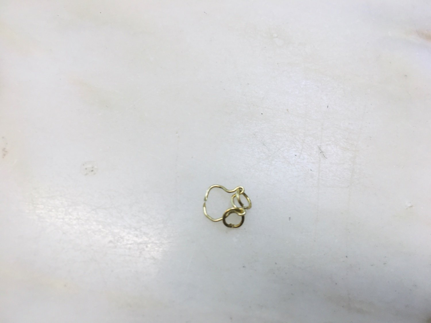
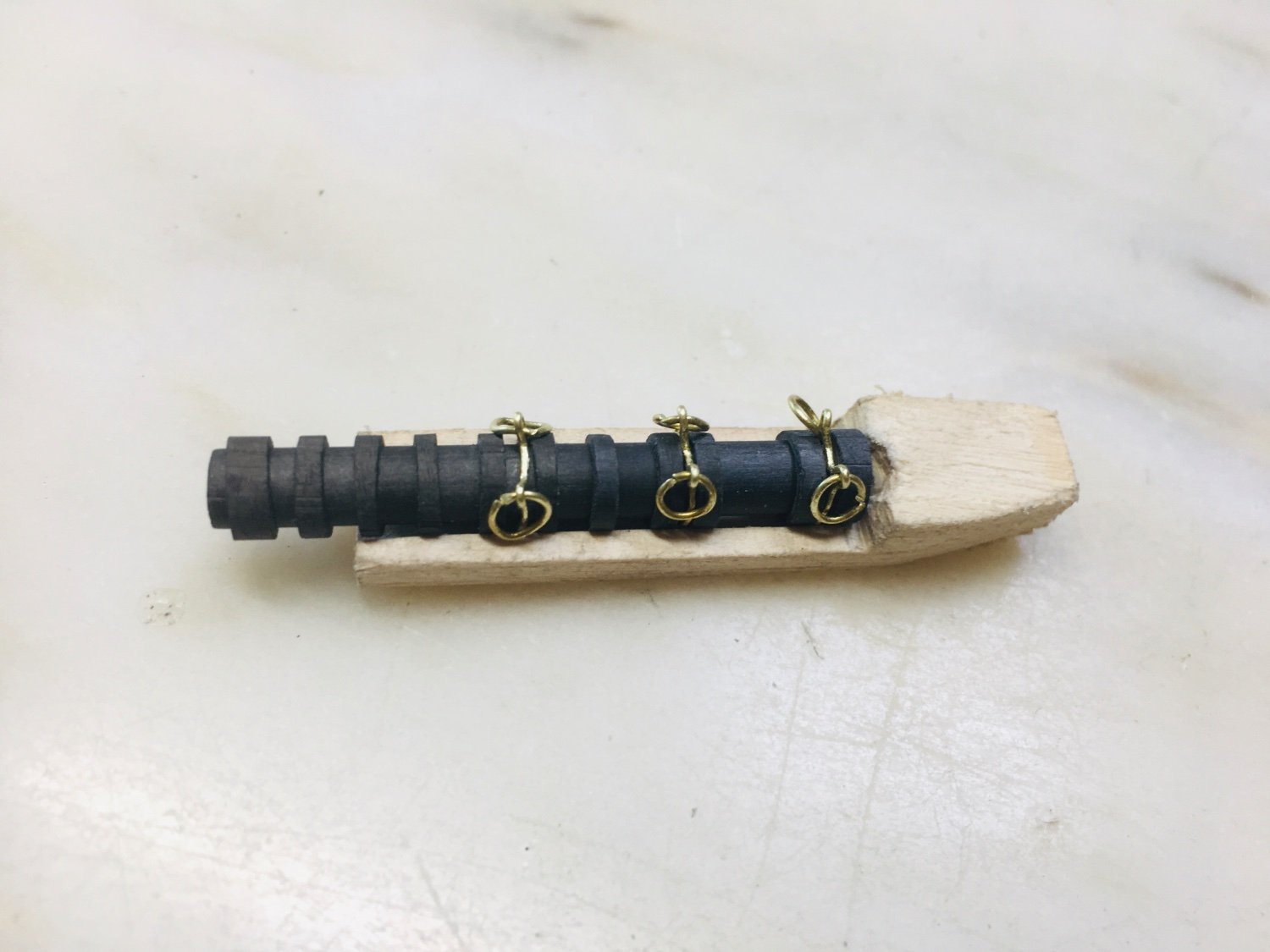
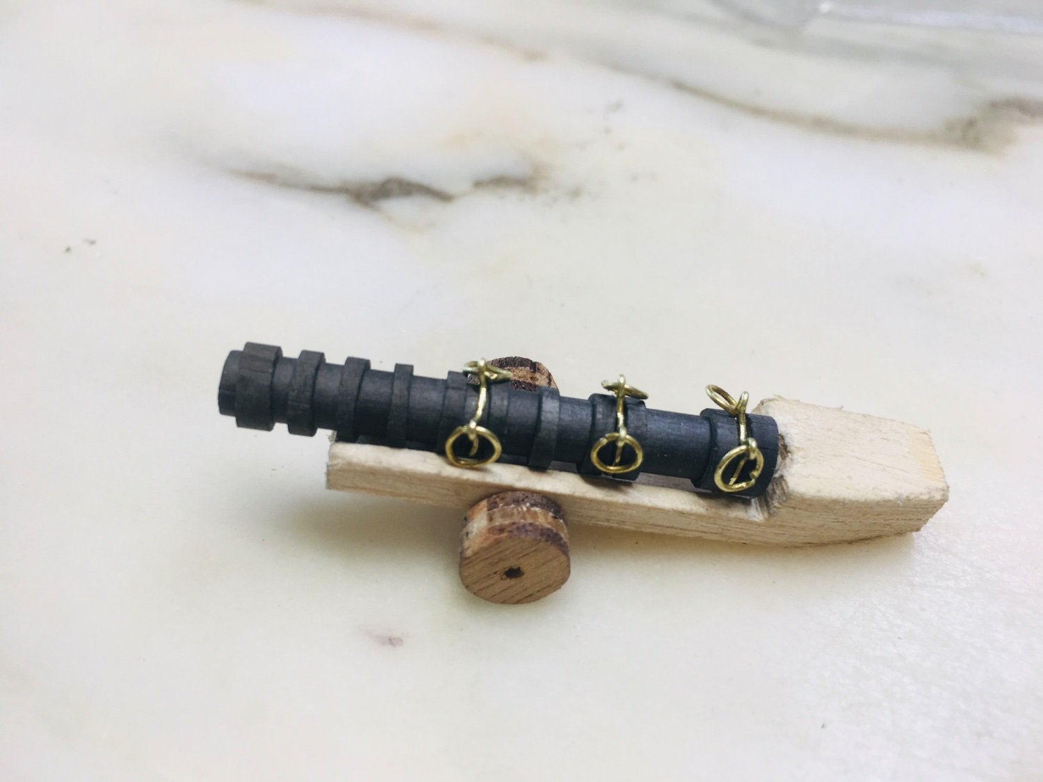
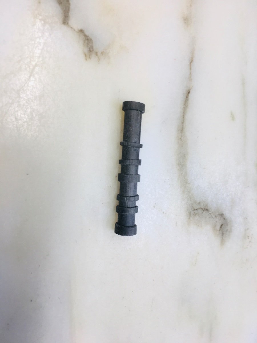
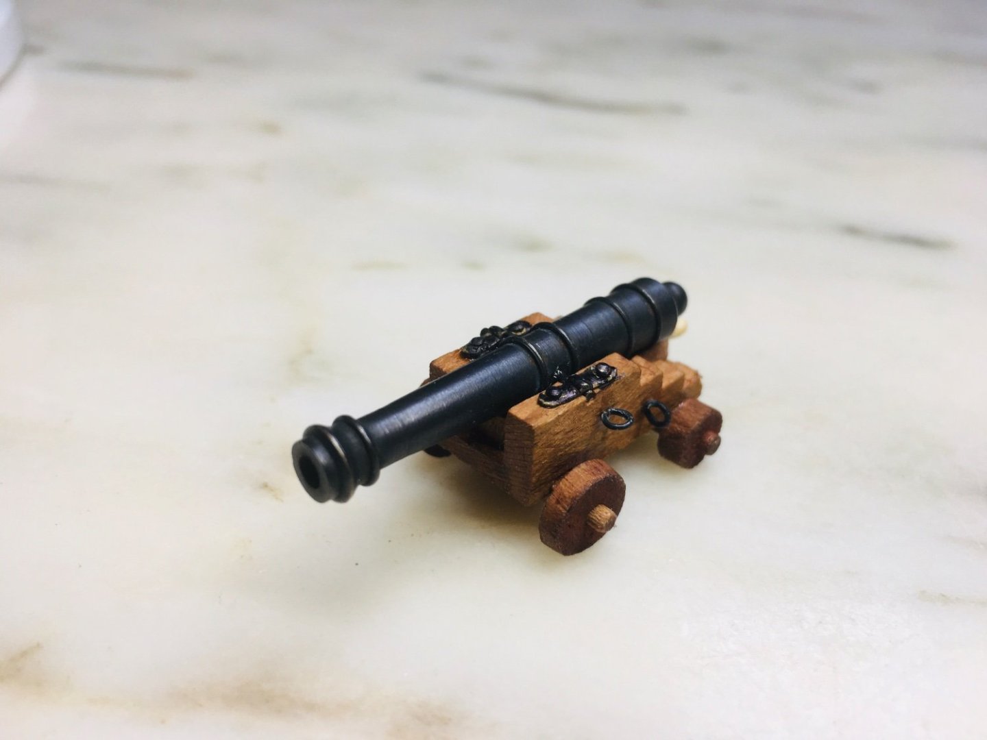
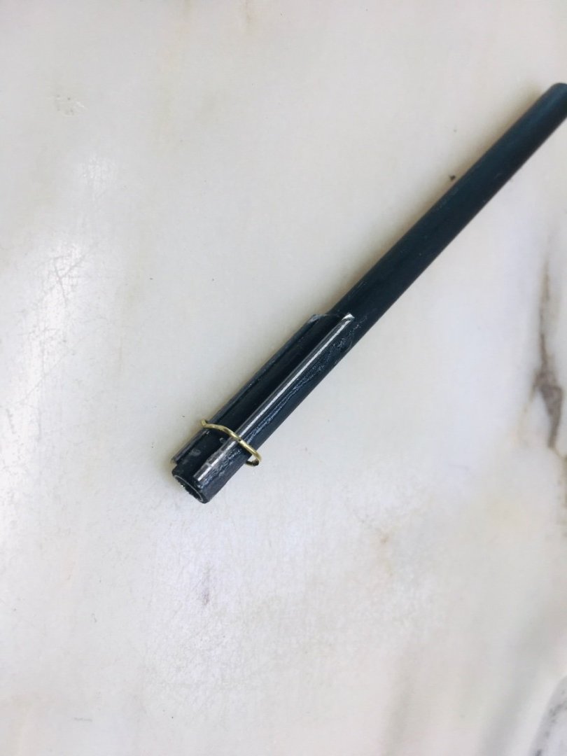
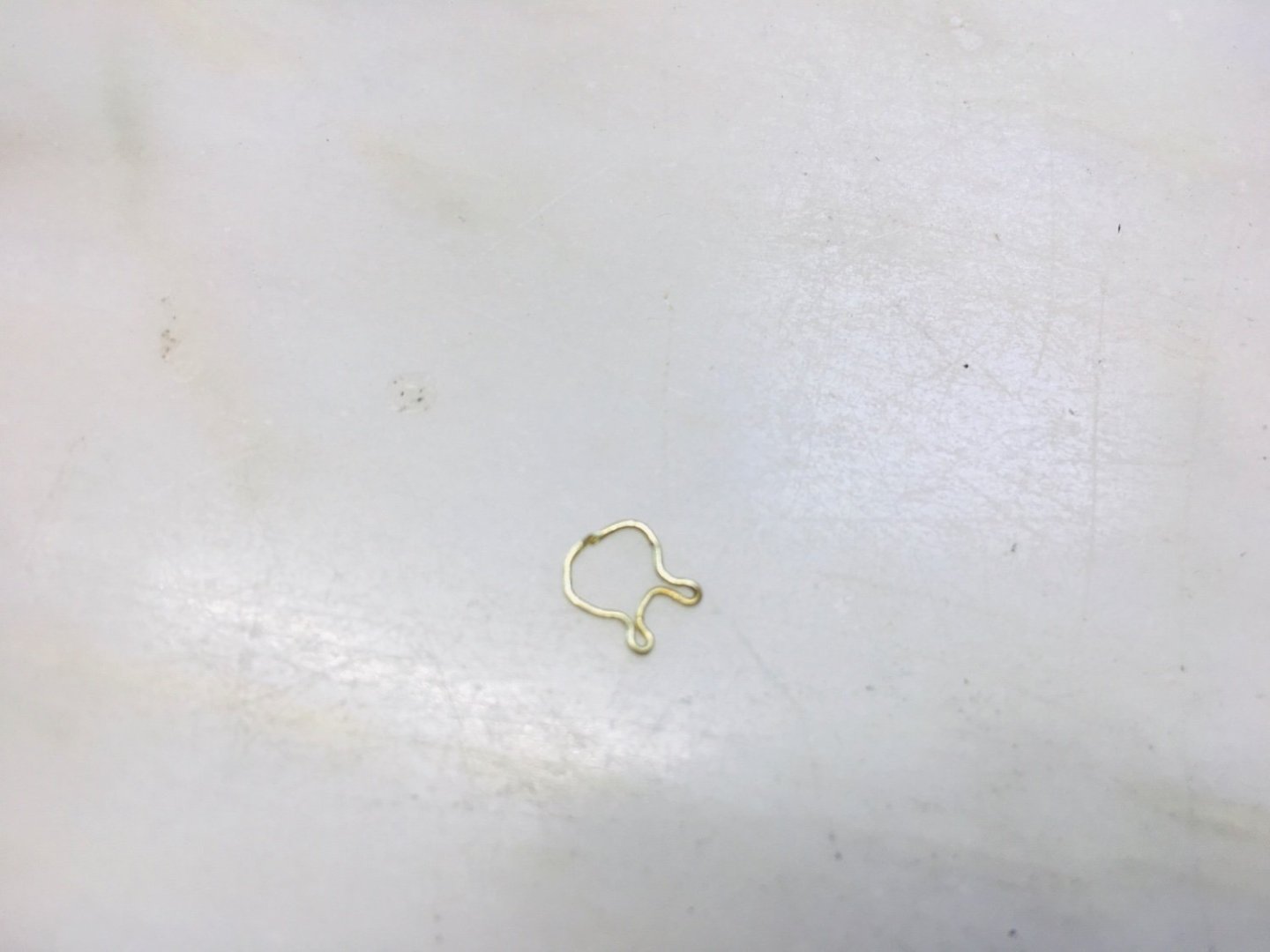
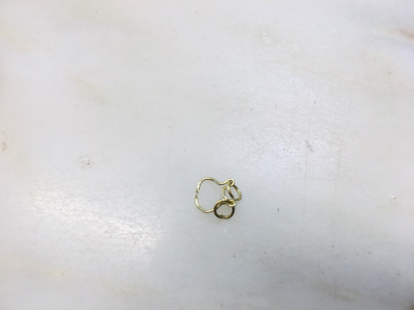
Work progressing on wrought iron cannons…the rings (and the attachment band to the barrel) used as handle (for transporting the lower removable part and the main cannon barrel) was devised with thin brass wire, formed around the thinner carbon/aluminum composite bow shaft (slightly modified to hold 2 small rings on each side). For some reason, this particular work is progressing quite slowly with limited results (also quite painful on finger). I am not sure if I want to apply 3 sets per barrel for all wrought iron cannons. I will see how the cannons look with and without them and decide later. In the meantime, I would appreciate and be grateful for any suggestions for alternative approach on this particular work stream (limitation : I just have hand tools and a few small electric tools at my disposal). The overall look with a test wheel looks OK~


-
Hi GrandpaPhil~ Thanks very much for your compliment! Your method of using tooth picks and paper bands also look nice and original.
-
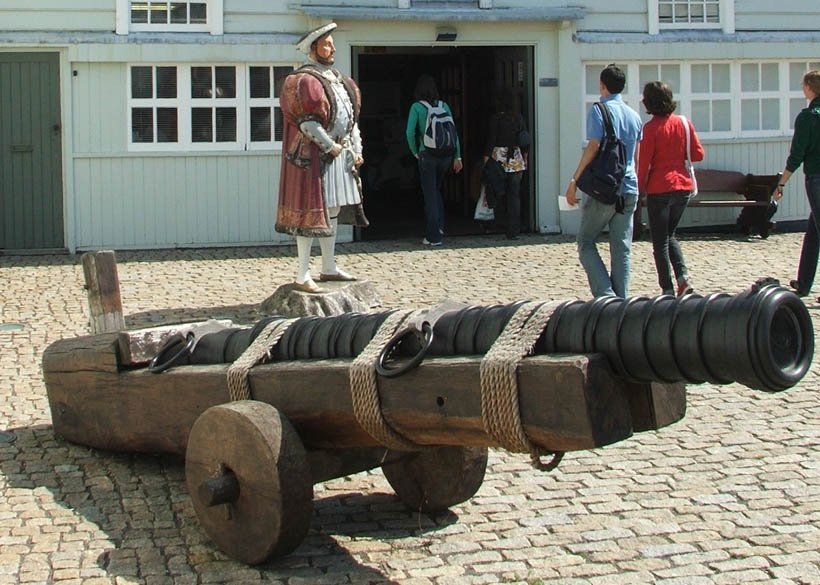
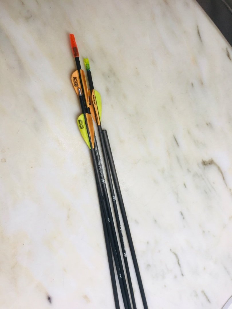
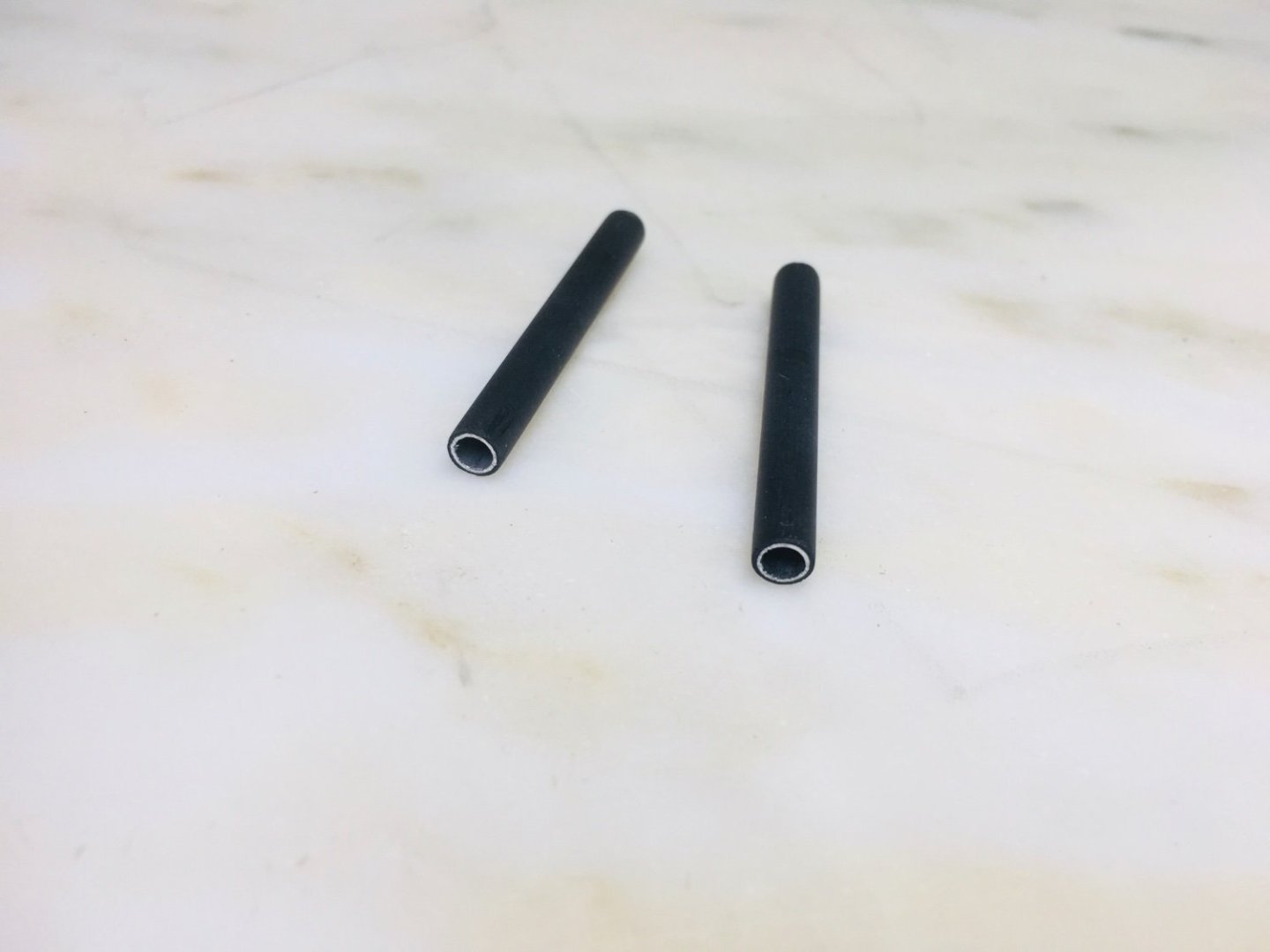
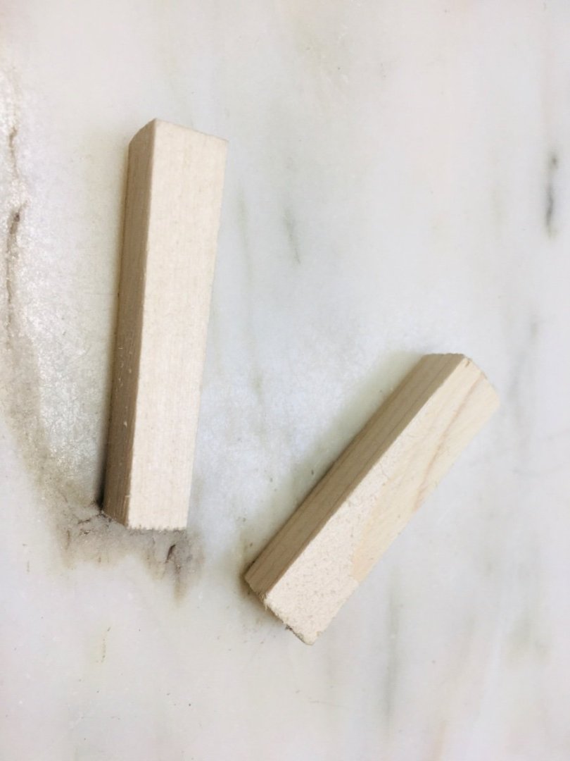
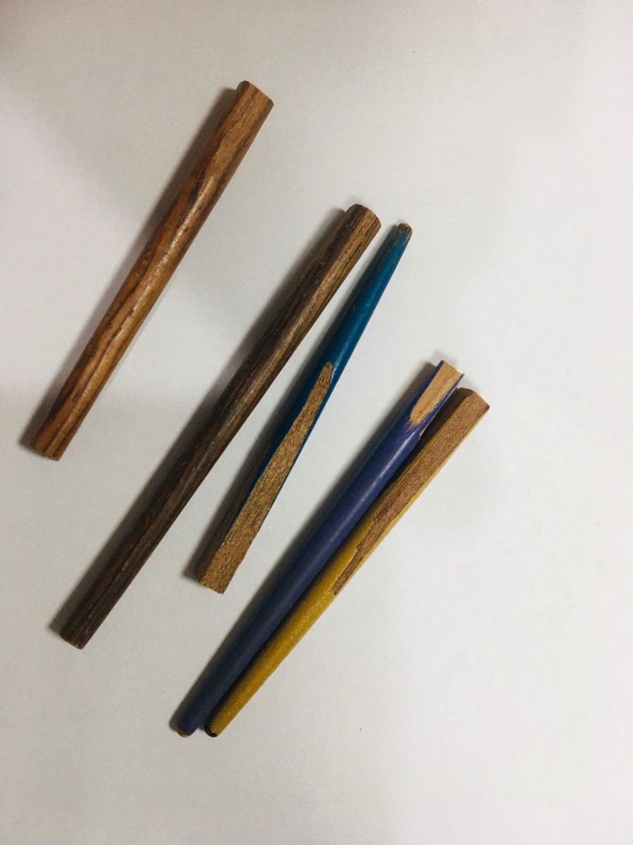
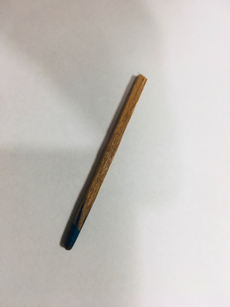
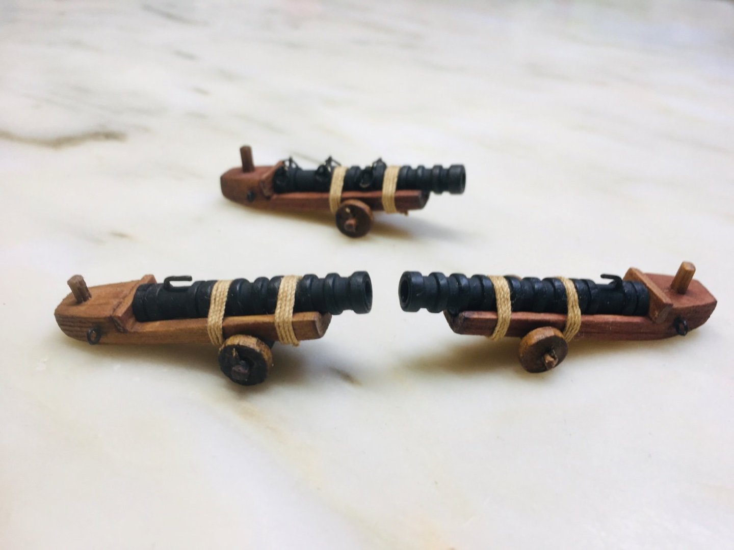
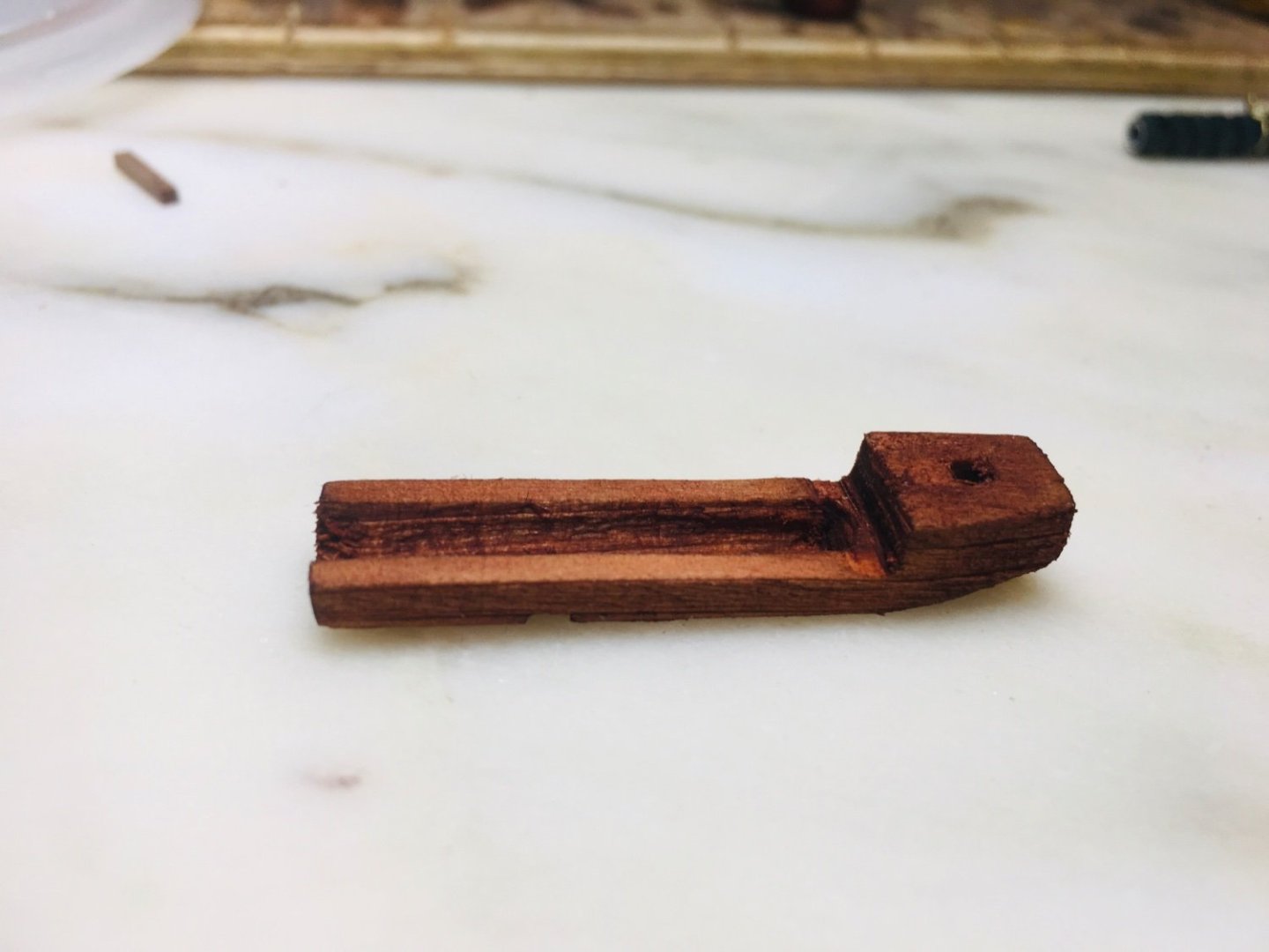
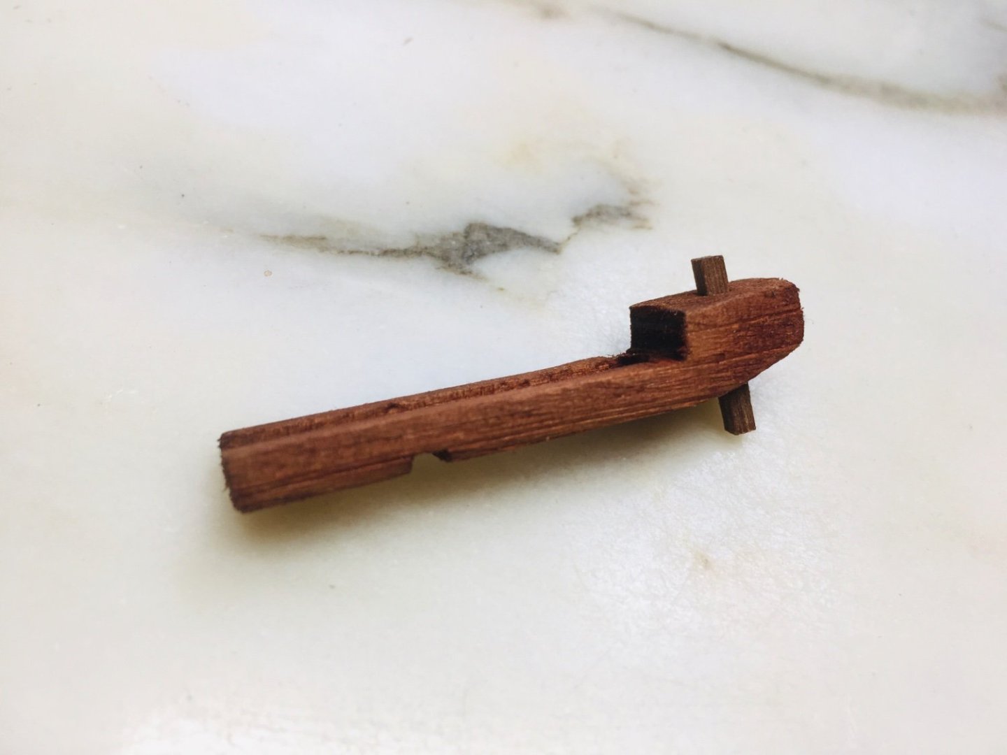
Now on to building cannons~! I have given much thought on what type of cannon to apply on my GH. After much consideration, I decided that wrought iron cannons (the likes of which were found on Mary Rose) should be the main guns to be placed on the weather deck. I have referenced various sources and decided to benchmark the below design. I have contemplated about various materials and methods of making the gun barrel. And finally, I decided to use decommissioned carbon/aluminum arrow shaft and carbon arrow shaft ( yes, I know it sounds weird… but olympic archery and Kendo are some of my other hobbies~). The above arrow shafts are hand picked for this task as they fall into the exact diameter specifications that I need for the right scale. First the smaller diameter (about 4mm) carbon/aluminum composite shaft are cut to 35mm and 39mm ( wanted to see which version would look better) Next step- the bigger diameter carbon arrow shaft is cut into about 1.5mm length and then put over the smaller diameter carbon/aluminum shaft as below. The above first prototype is based on 35mm length barrel. I think I may need to go for 39mm length. On the cannon carriage, I decided to try a soft wood first. Initial design looks OK overall, but I will definitely go for longer barrel. Also, more refinements are needed.