

Jay 1
-
Posts
618 -
Joined
-
Last visited
Content Type
Profiles
Forums
Gallery
Events
Posts posted by Jay 1
-
-
Build Decisions
I've taken a brief pause before I move on to the 2nd planking. The True Vine's actual gunwales dimensions were 9 inches wide (~23 cm) and 5 inches thick (~13 cm). If I model those, I'm not sure if the scale gunwales will play nice with the available space at the stem and stern. The wood for the gunwales should arrive next week, and when it does, I'll begin dry fitting / testing the gunwales to see if they'll work.
I also paused while I made decisions about additional wood for a few other features as well. A biggie here was whether to use the kit's design for the bulwarks frame timbers or modify. Chris' design for the bulwark timbers is fantastic, it's just that the kit's design here doesn't quite fit for the Vine. Essentially the decision about modifying the bulwarks frame timbers came down to whether or not I was willing to do a lot of fiddly work. In the end, doing fiddly work won.... 🤣
Cheers,
Jay
- JacquesCousteau, BobG, Thukydides and 2 others
-
 5
5
-
Thanks for jumping aboard, Bob! Sorry I didn't acknowledge you sooner fellas: Shouts out to Jacques Cousteau, Thukydides, and Keith for your interest as well and also for everyone's likes!
Bob, what you said about these boats are why I'm drawn to them as well! And the regional variations throughout Europe and the US (as well, elsewhere) offer seemingly endless subjects for modeling. While I appreciate sailing warships, the bluff bows and lines of the 18th and early 19th Century ships don't captivate me like these little guys.
Cheers,
Jay
- Keith Black, JacquesCousteau and BobG
-
3
-
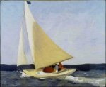
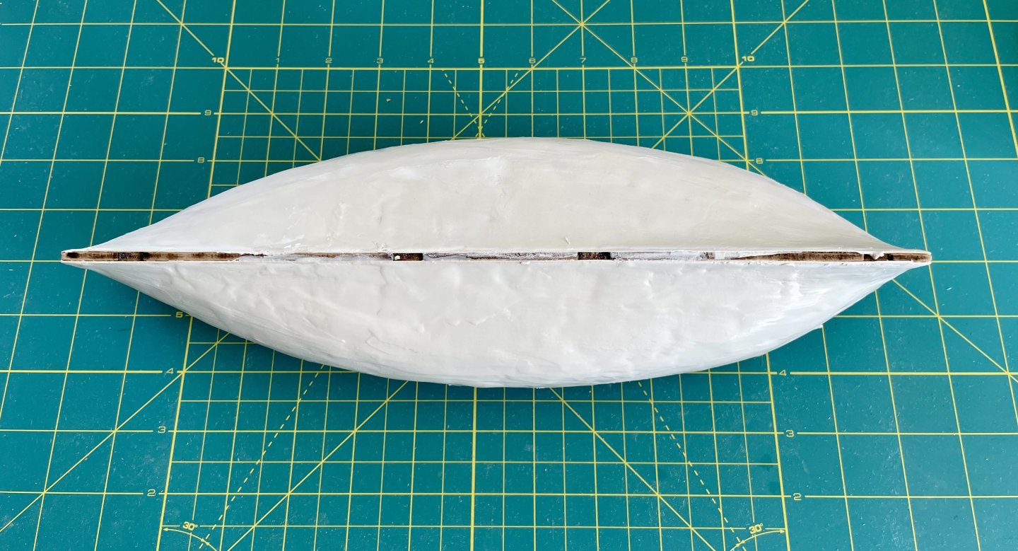
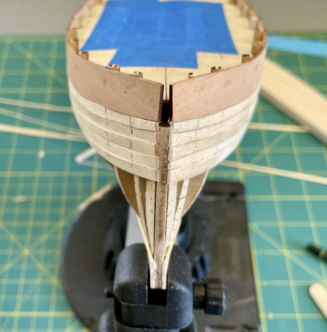
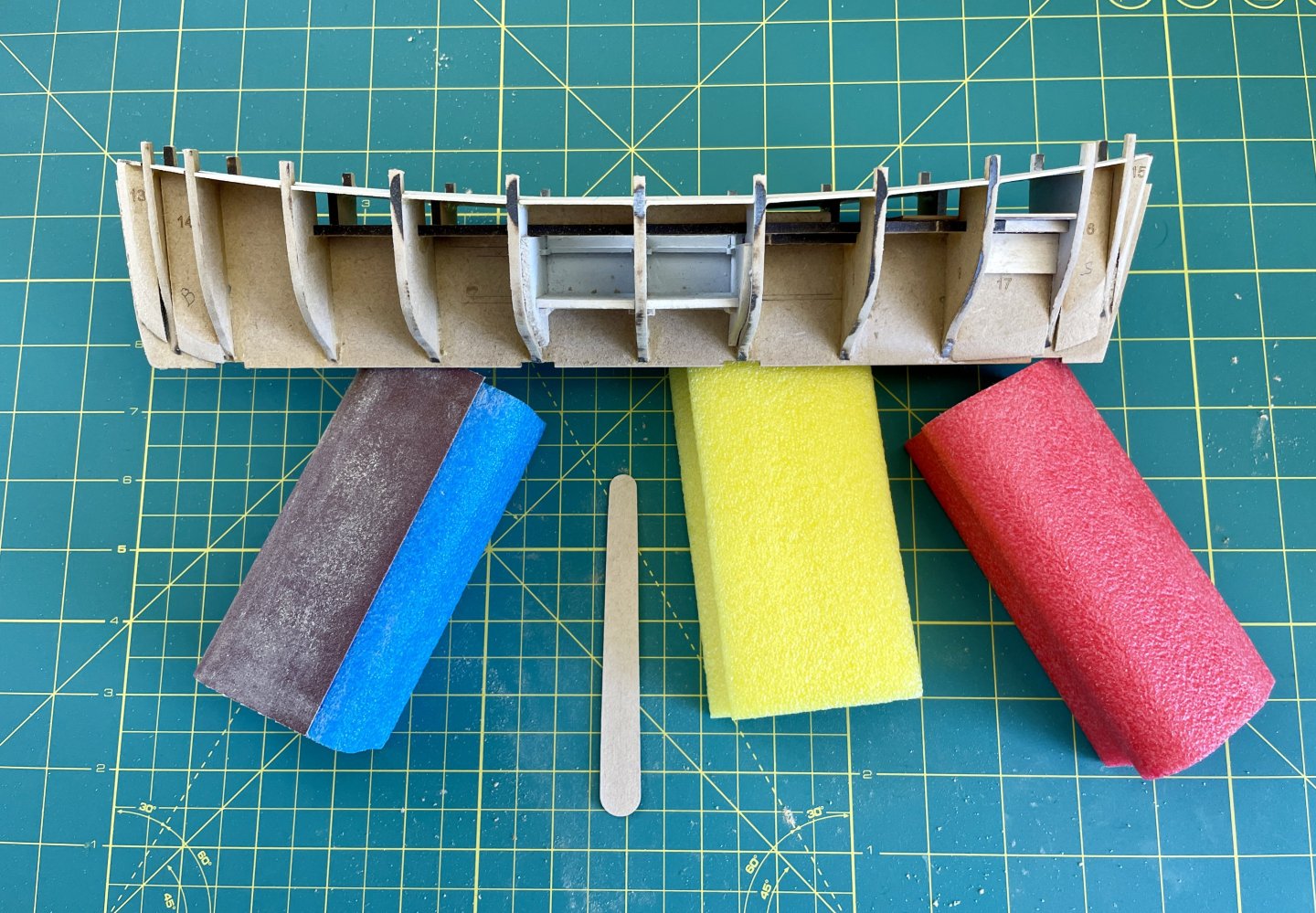
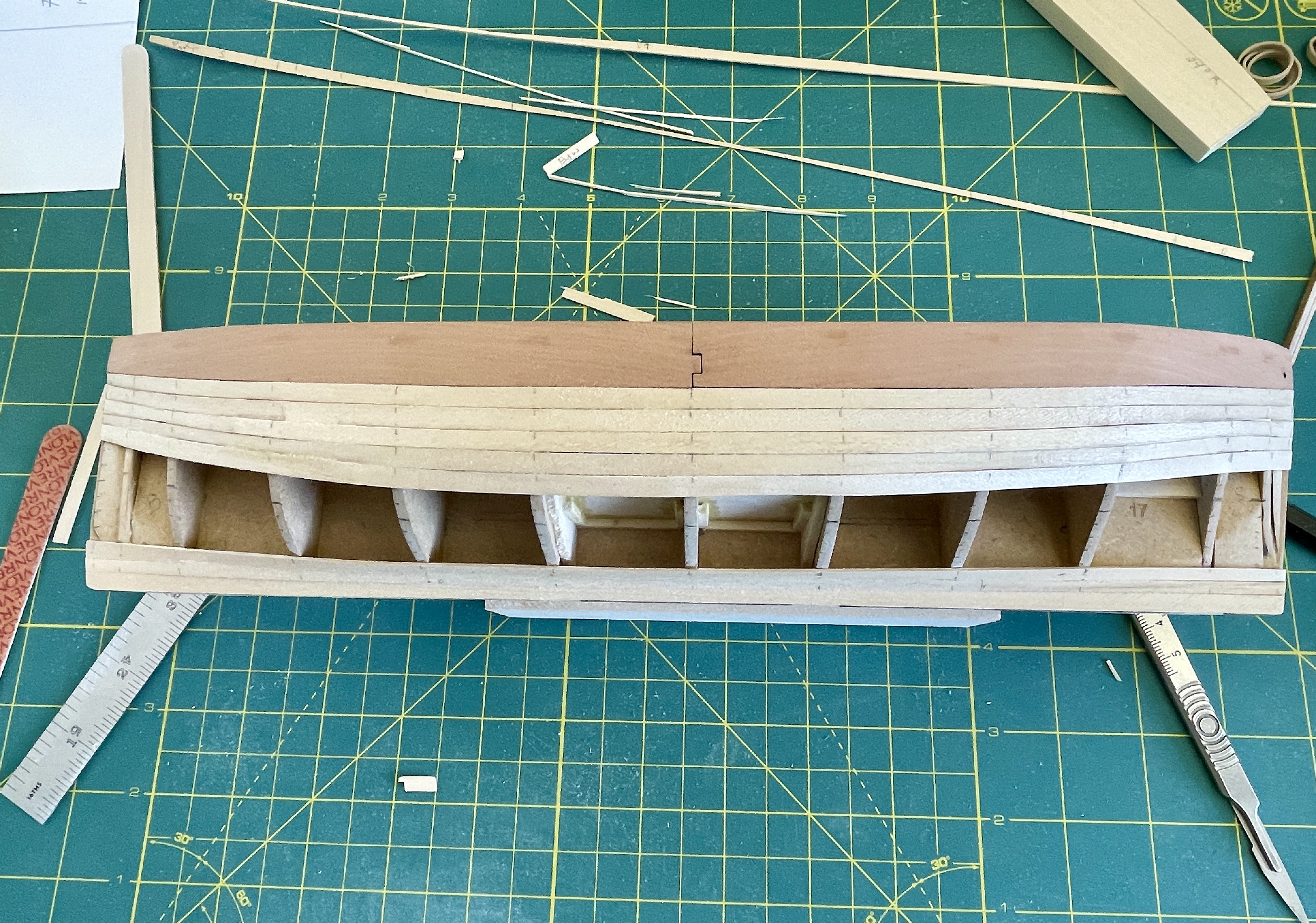
Hull Construction – 2nd Planking Prep
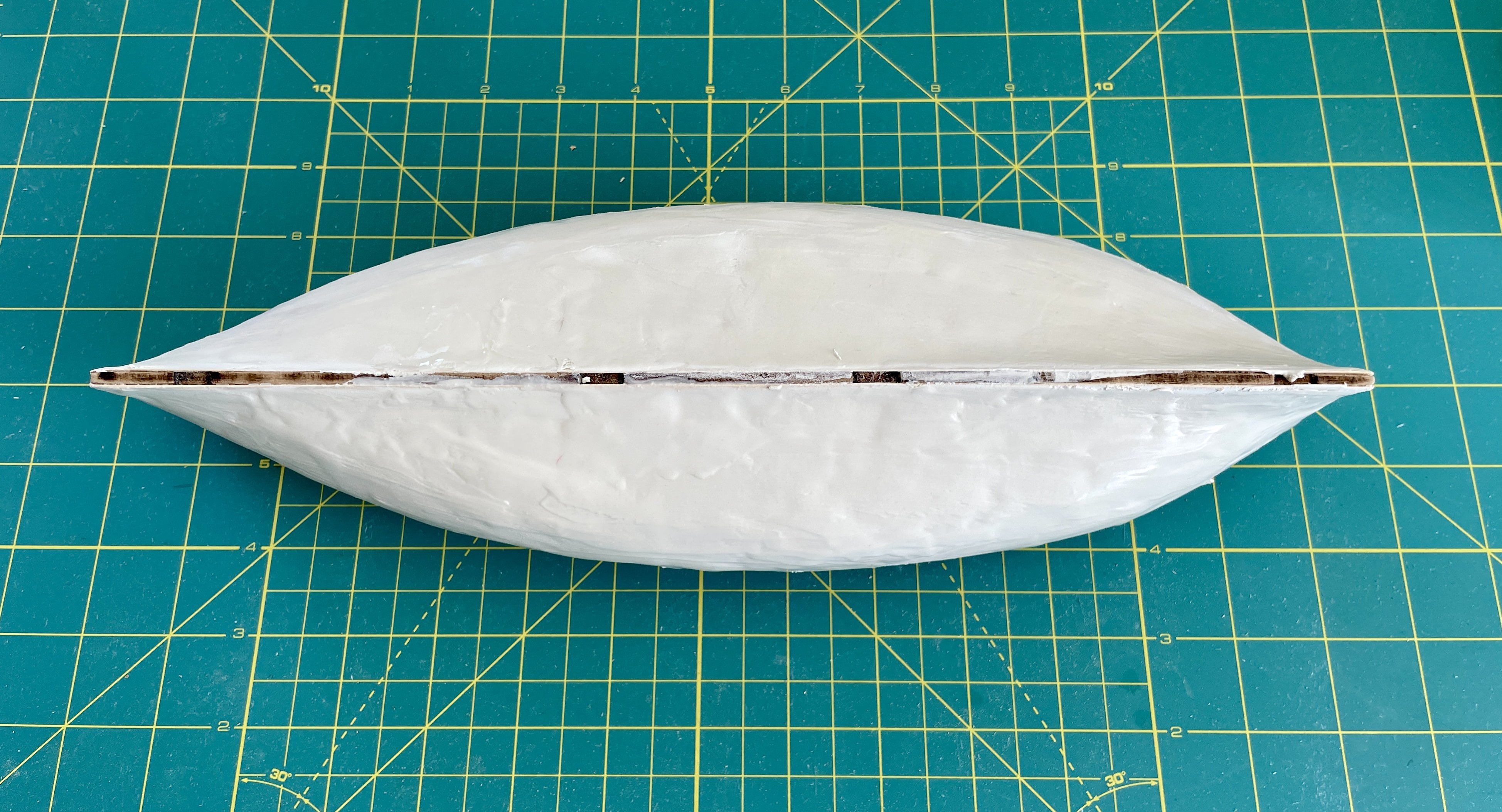
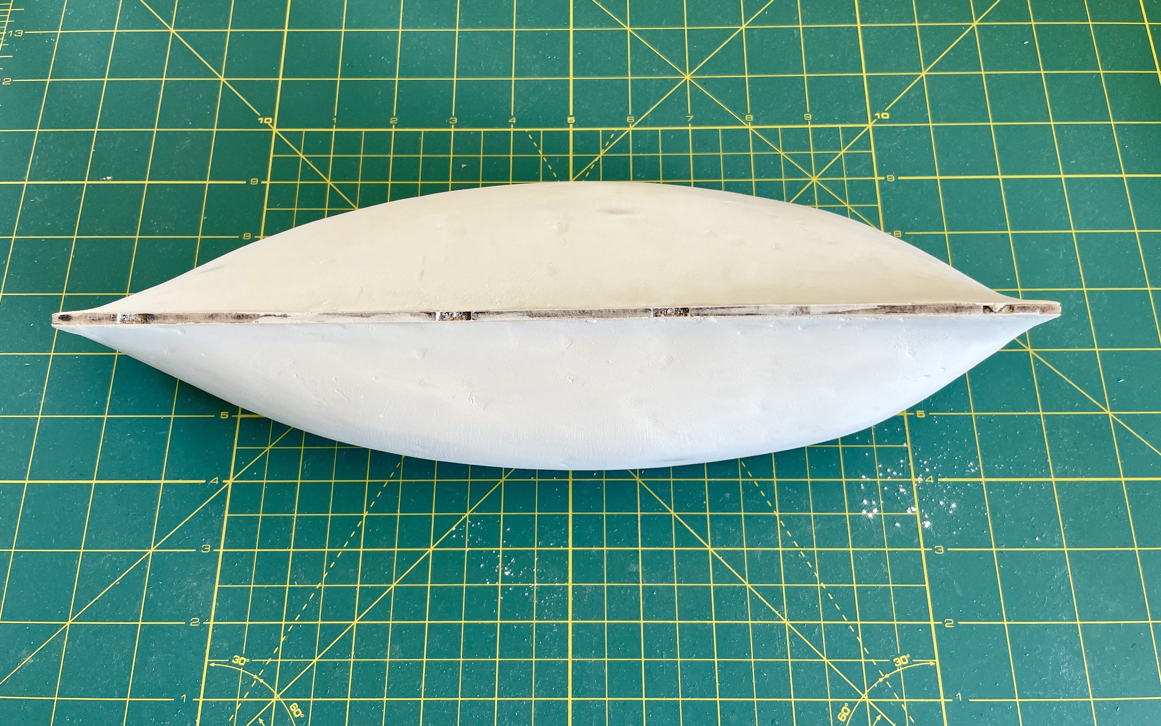
After finishing the 1st planking, I steamed it to help level uneven planks and etc. I then sanded out high spots.
A trade I practiced when I was younger was interior wall repair (I still do repair work for family and friends in need). I used that skillset to fill and finesse the hull in preparation for its 2nd planking.
The pics that follow are the progression of finessing the hull. Although the hull looks like hell in the last photo, it actually is exceptionally fair.
I then sealed the hull with shellac, scuff sanded it with P180, and then rough-marked bulkhead locations for the 2nd planking.


Cheers,
Jay
-
Hi Paul, excellent—thank you for your feedback and help!
Jay
- Paul Le Wol, mtaylor and Canute
-
3
-
What sizes of extra wood do you recommend getting for a Cheerful build? I’m going to order a cut package for the build and figured I would add some extra wood based on the experience/ recommendations of builders who ran short on wood during their builds.
Thanks in advance for your suggestions!
Jay
-
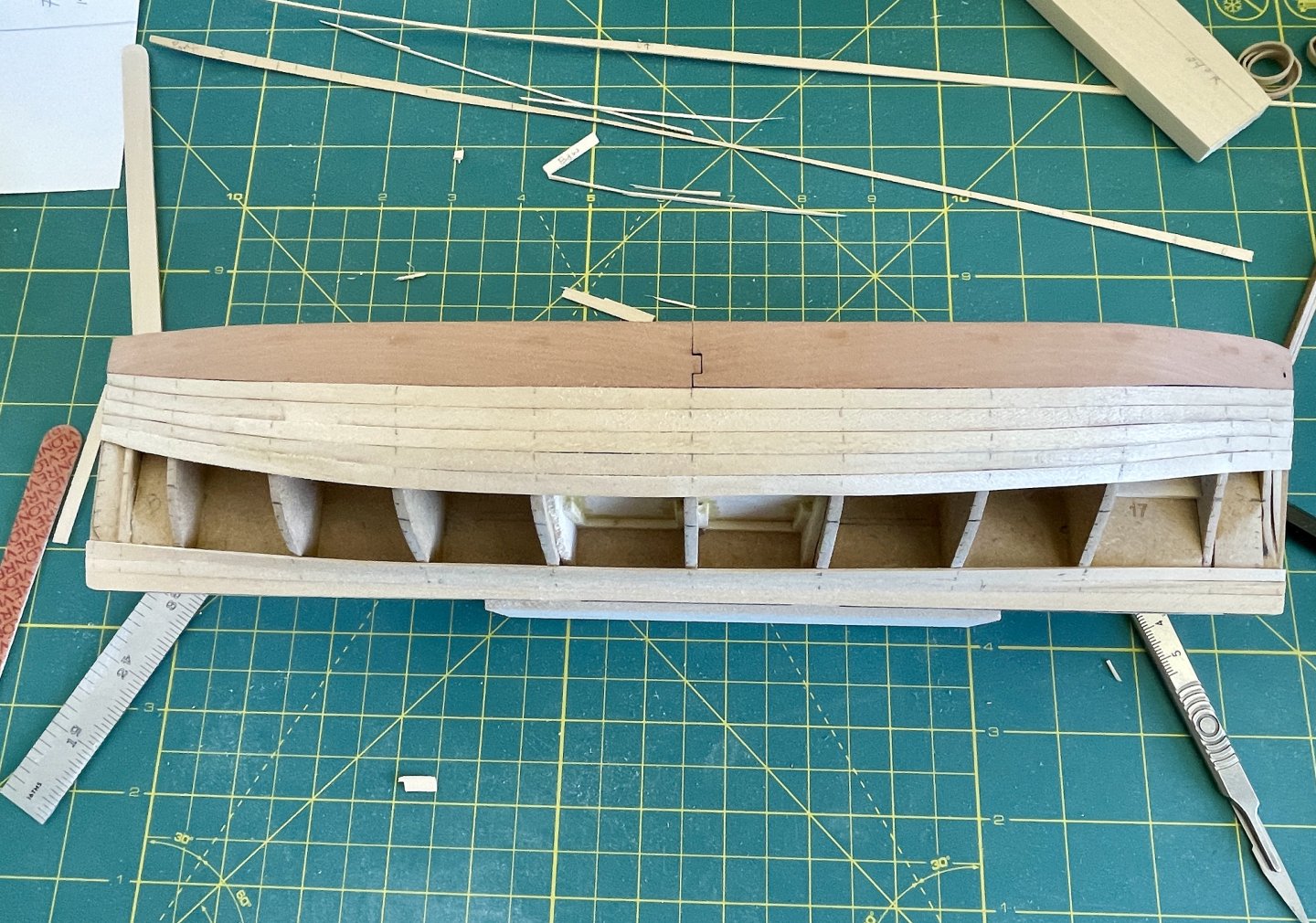
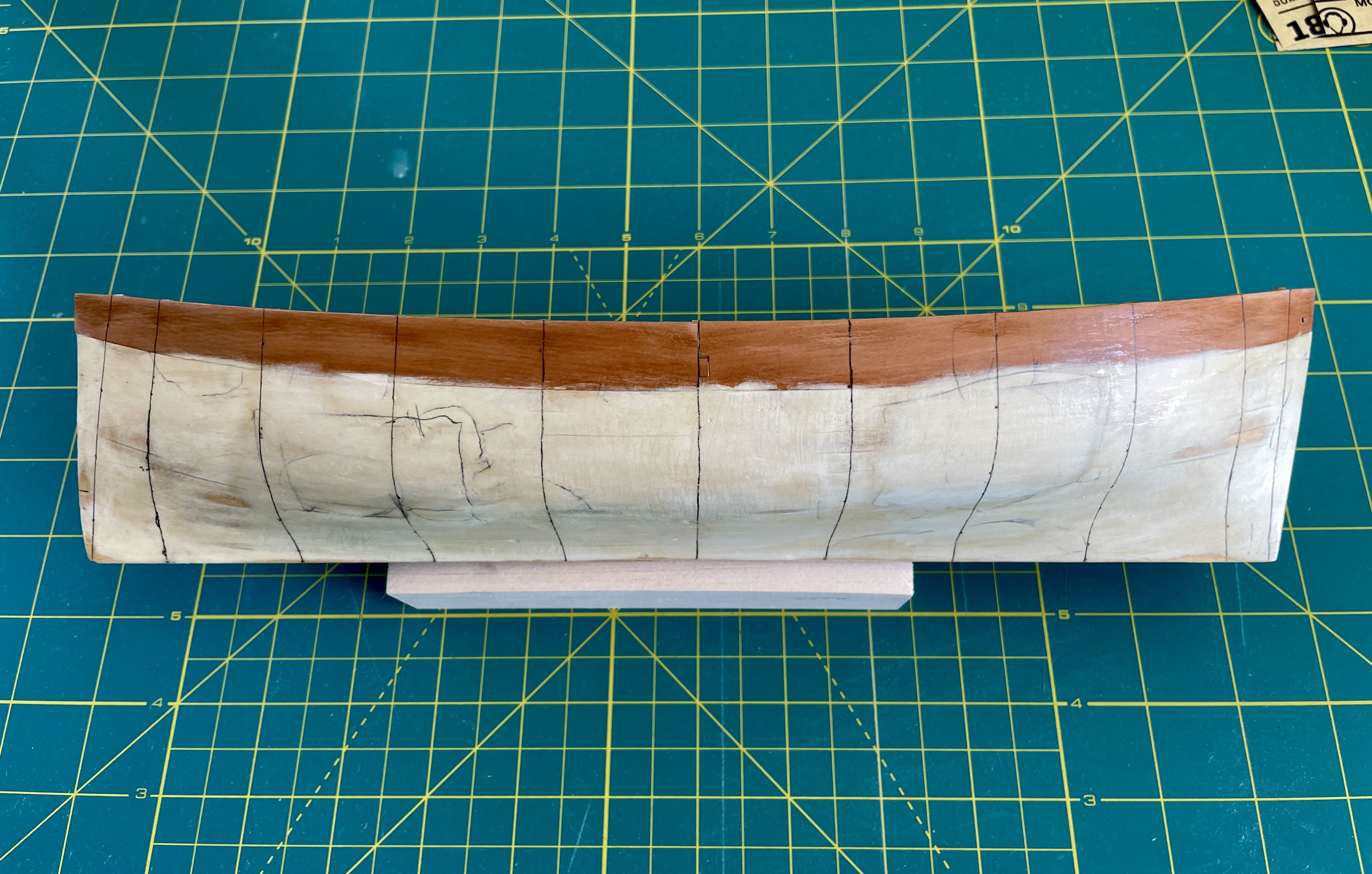
Hull Construction – 1st Planking Finished
She’s starting to look like a Boaty McBoatface! 🤣
Boaty McBoatface aka the "Sir David Attenborough"
Caught Covid this Friday while on my way home from work travel, so got a Paxlovid script and finished the 1st planking in-between naps and etc.

Cheers,
Jay
- BobG, ccoyle, JacquesCousteau and 2 others
-
5
-
Well done and congratulations! 🎉
-
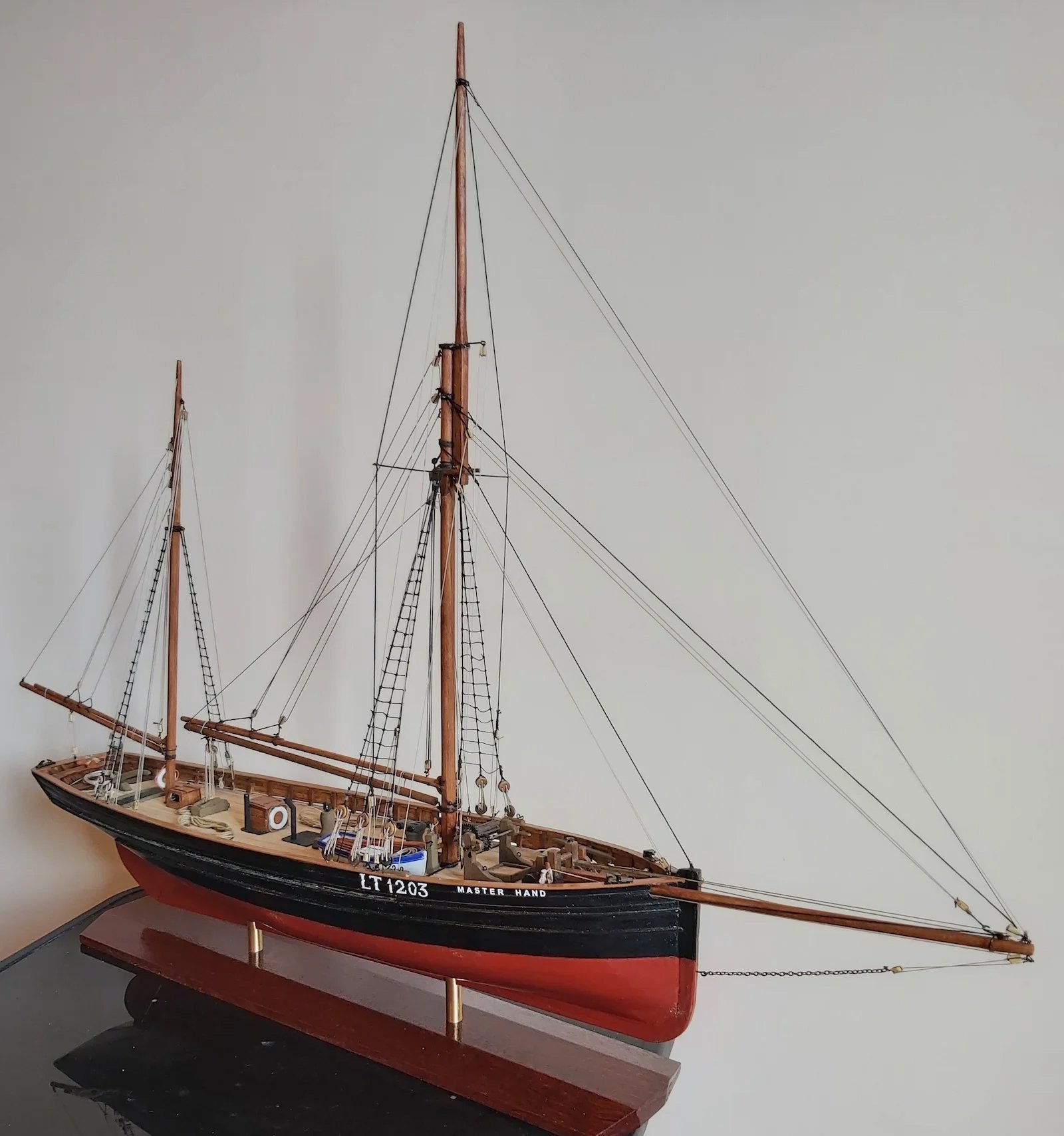
Thank you, BE! Your "Lady Eleanor" and "Muirneag" builds were, and are, inspirations for my build. Like you, I'm also fond of these fishing boats--they have so much character! To build back my modeling skillset after such a long break, I plan on building several of Chris' fleet--plus, they'll make nice gifts.
Oh the Master Hand was lovely--what a sad fate she came to. Hopefully Chris will consider adding her to his line up...we definitely know there are at least 2 builders that will go for her! 😉 Had to include her image below to maybe sway Chris in case he drops in.....

Source: Capt. David Bray's lovely build at: https://nauticalnostalgia.com/model-making-model-engineering/master-hand/
Cheers,
Jay
-
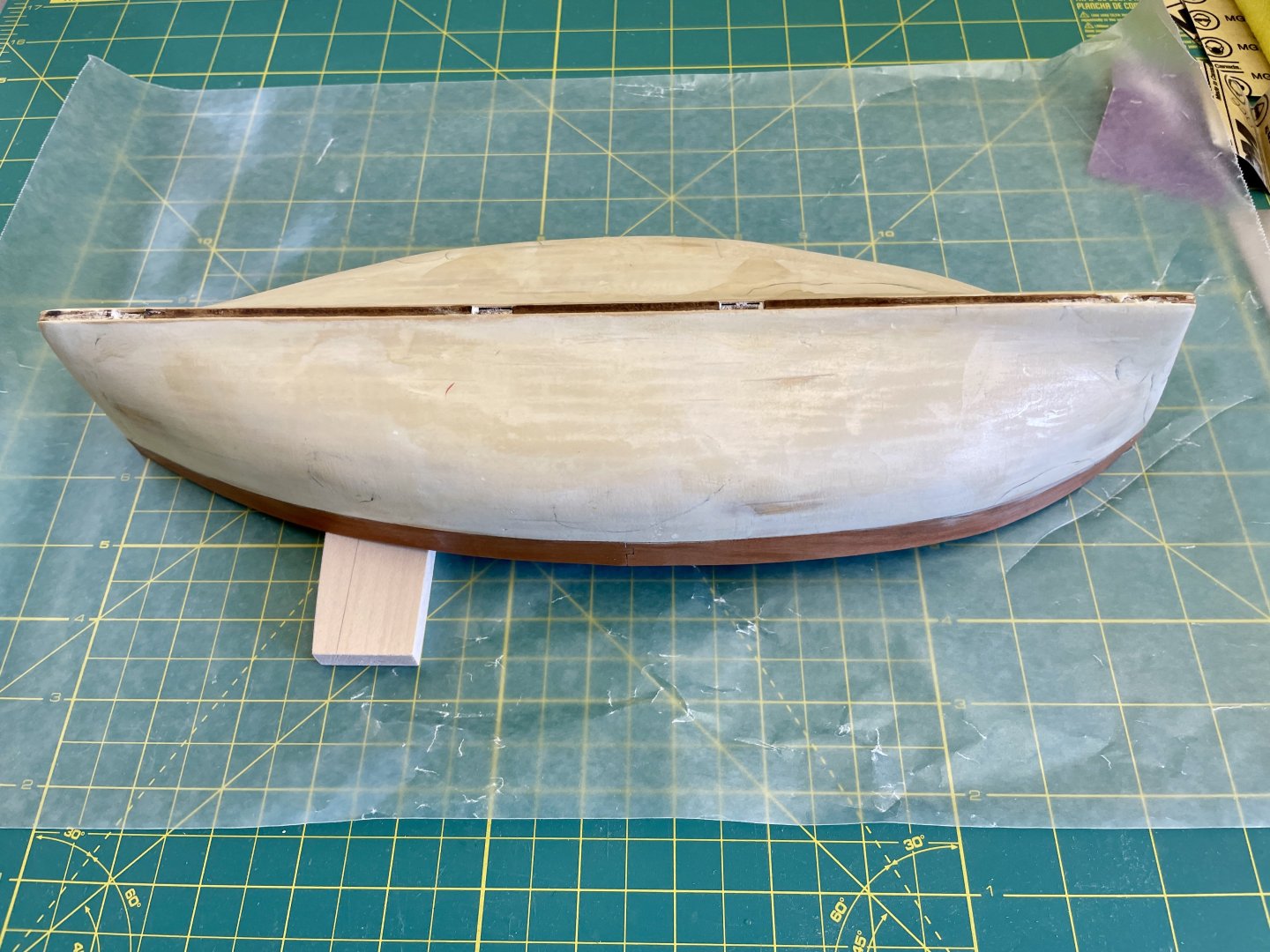
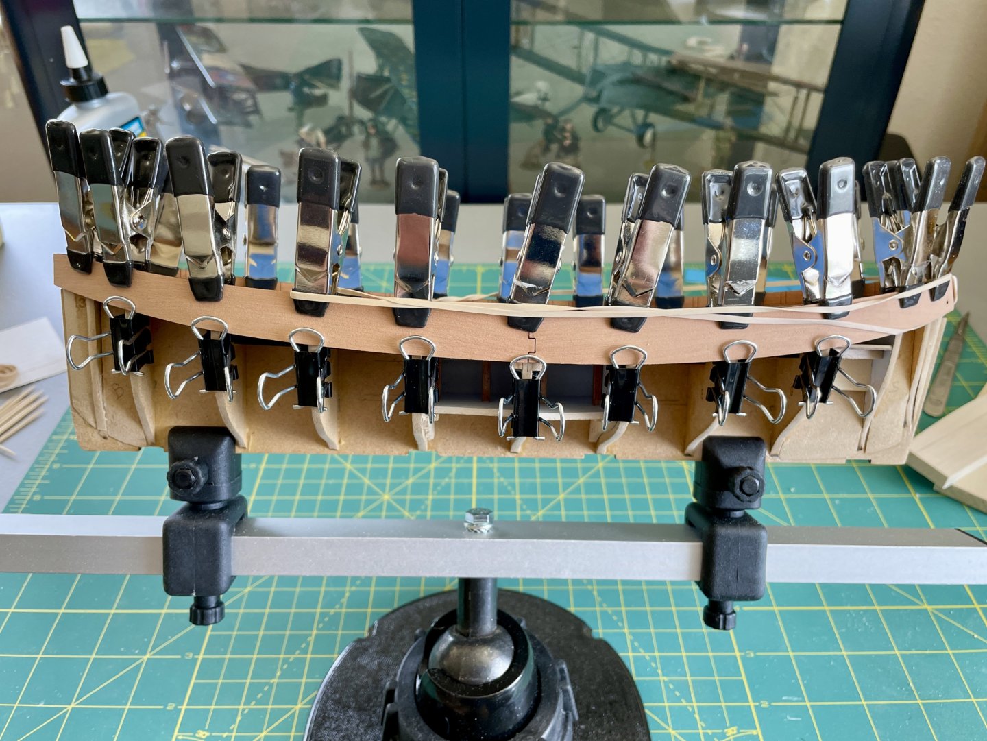
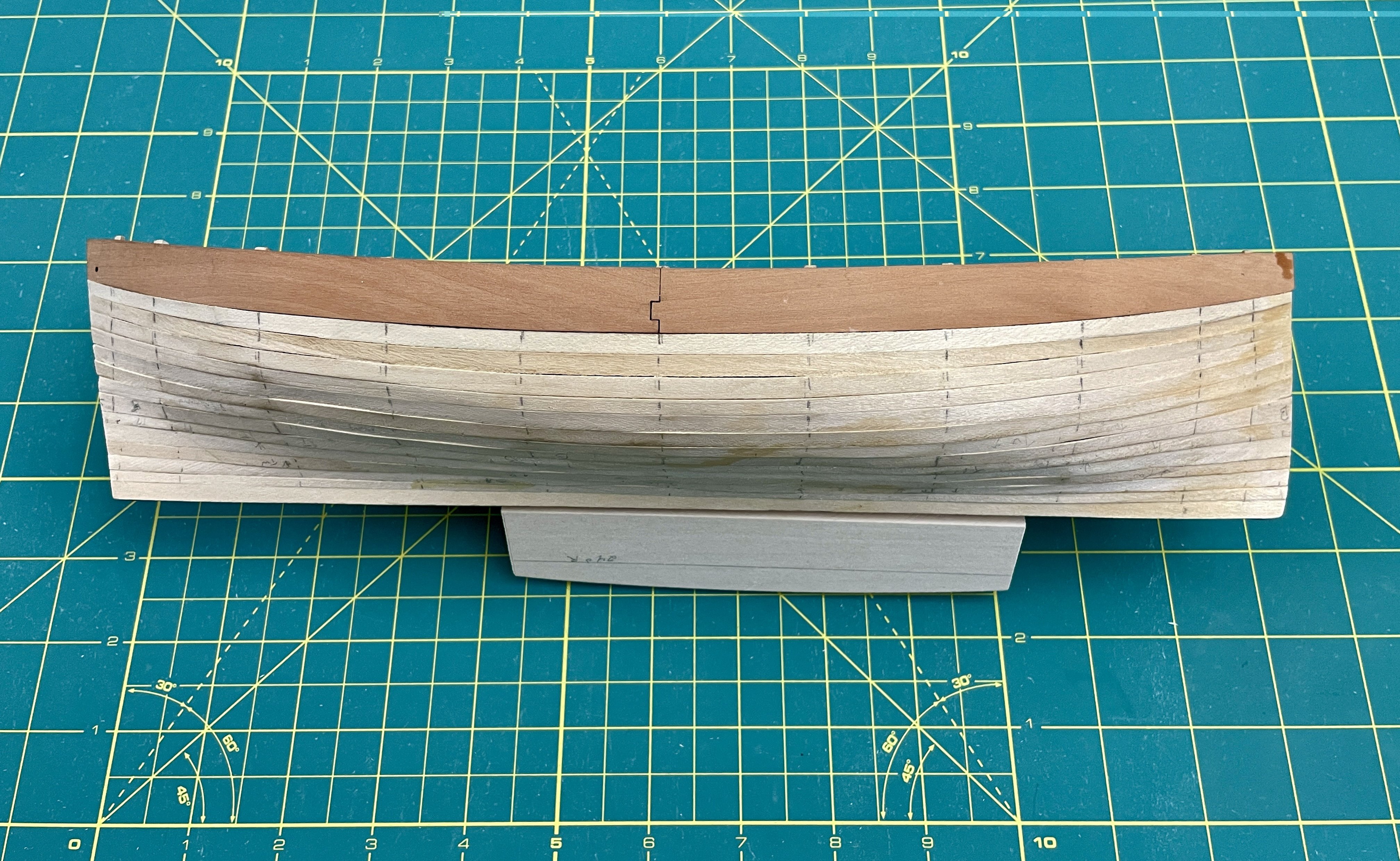
Hull Construction – 1st Planking
I also began planking the hull with its 1st layer of limewood. I decided to follow the more standard method of lining off the hull. It’s been a long time since I did any planking, and I definitely needed the practice! A part of my planking practice was aiming for symmetrical planks at the bow and at the stern. I worked down from the bulwarks and then up from the keel and completed 16 strakes and have 14 to go, which I’ll complete when I return from work travel next week. I'm using a combination of PVA and CA to secure the planks. I then lightly brushed PVA inside the planked areas to help prevent any planks from popping up. Overall, I’m feeling pretty good thus far about my planking.
A Few Observations:
The midship bulkhead distance from the bulwarks to keel bottom is about 2mm wider than the kit’s planks. In other words, based on my measurements, a 7mm plank is needed for 1 strake on each side of the hull. I think Blue Ensign made a similar observation about wider planks with his Lady Eleanor build.
The thickness of some of the limewood varies, so there are height variations with planks—not a big deal for this layer but the thickness differences will make for a bit more sanding and etc. I think the thickness and the finish of the limewood can’t totally be helped though because it’s such a soft wood and likely difficult to mill.
Cheers,
Jay
- BobG, Thukydides and GrandpaPhil
-
3
-
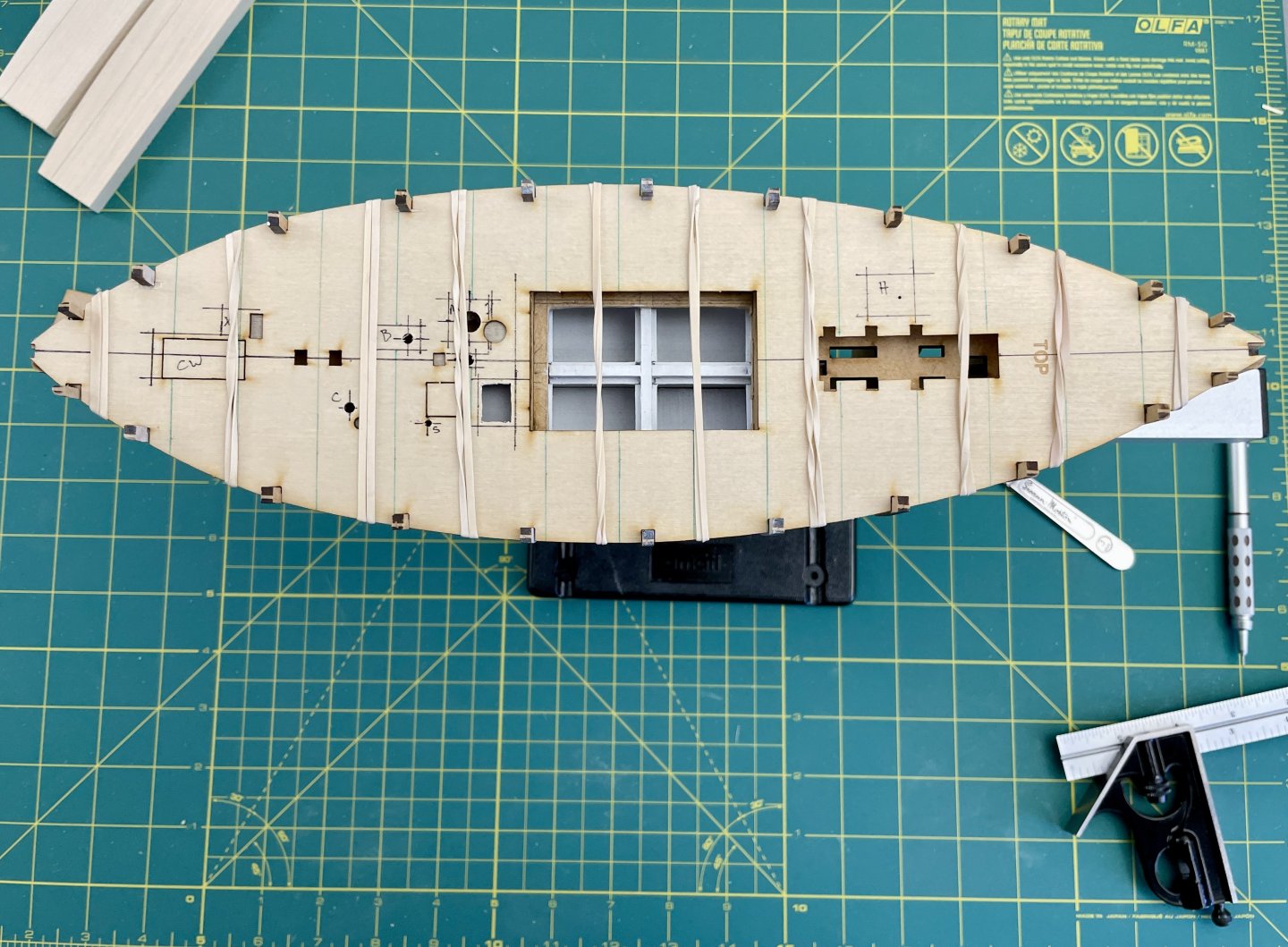
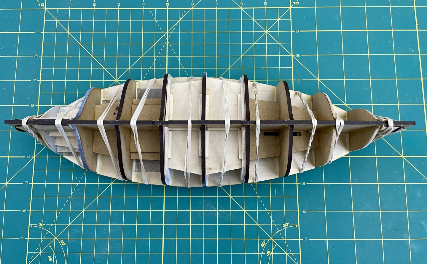
Hull Construction – Installing Bulwarks
I was able to get some build time in this week and followed the instructions for 1st forming the bulwarks and then doing their glue ups. This process went smoothly and with no hitches.

Cheers,
Jay
- GrandpaPhil and Thukydides
-
2
-
Thank you, Thukydides for your kind comment—adding the mods have been both fun and challenge! There will be more as I get further with the build that will be fun additions.
Cheers,
Jay
edited for grammar error
-
Current Build Status and Break
Now that I know my modifications won’t trash the model and actually worked out okay, from this point forward, my log will reflect my where I’m actually at with my build which is installing the bulwarks and planking.
Because I have a lot happening at work next week and then am on the road for work again the following week, I may not be building much, if at all, for next couple of weeks.
Cheers,
Jay
-
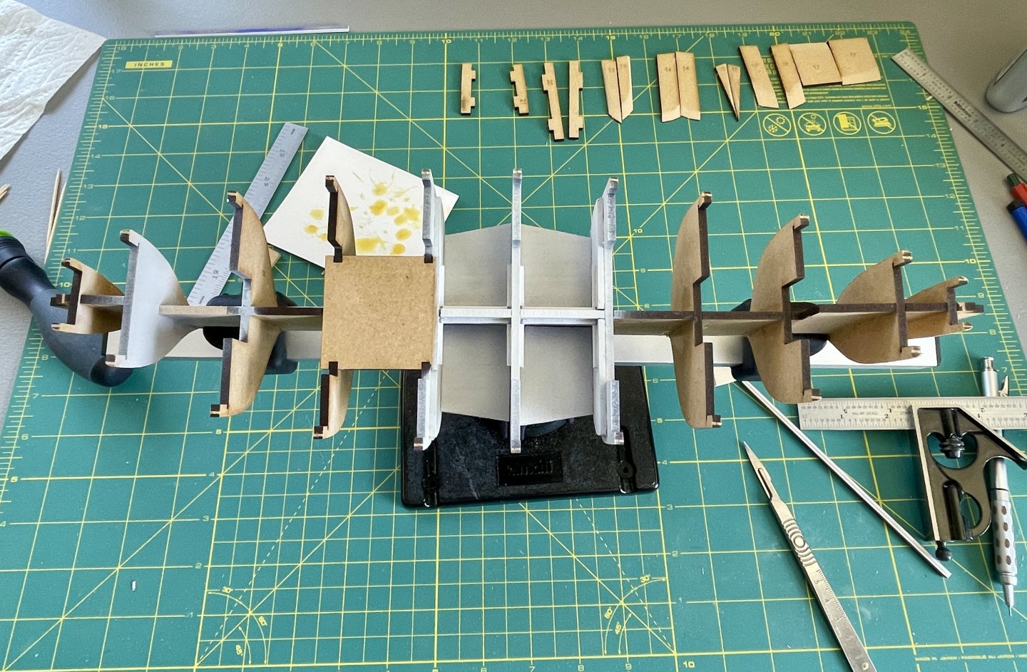
Subdeck Installation and Fairing
The milestone with the deck layout / hull modifications was installing the subdeck. Even though I reinforced the subdeck with birch plywood, I still didn’t know if the subdeck would or would not split from all the modifications I made to it.
Additionally if the subdeck didn’t split, I also didn’t know if it would be able to bend enough into its BH positions due to its added reinforcement. I knew pre-shaping the birch plywood strips would help with bending but still the ply was additional layer of wood that would decrease the subdeck’s flexibility.
Overall, fairing went well. The only real issue I encountered was with BH 1. While a batten ran fair from the bow infill piece, atop the upper sections of BH 1, and back to BH 4, the same batten didn’t touch the lower sections of BH 1 but did run fair from the bow infill piece to BH 4. I think reason behind this issue was operator error when I beveled the port and starboard lower sections of BH 1: Either my bevel angle was wrong or I just simply took off too much MDF. At any rate, I shimmed the lower sections of BH1 and made adjustments until I got fair batten runs from the bow to BH 4.
Cheers,
Jay
-
Deck Layout / Hull Modifications Pt 3
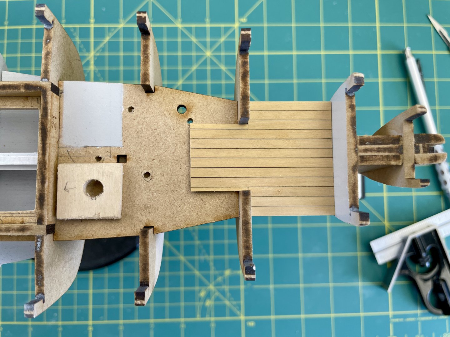
I plan on having the entryway to the companionway open; thus, the details that follow should hopefully be visible to a viewer. Some may notice I didn’t make a companionway cutout on the subdeck. The reason for this is the companionway’s position is dependent on the positions of an aft steering assembly and thwart. After I determine those item’s 2 positions, I’ll then make a subdeck cutout for the companionway.
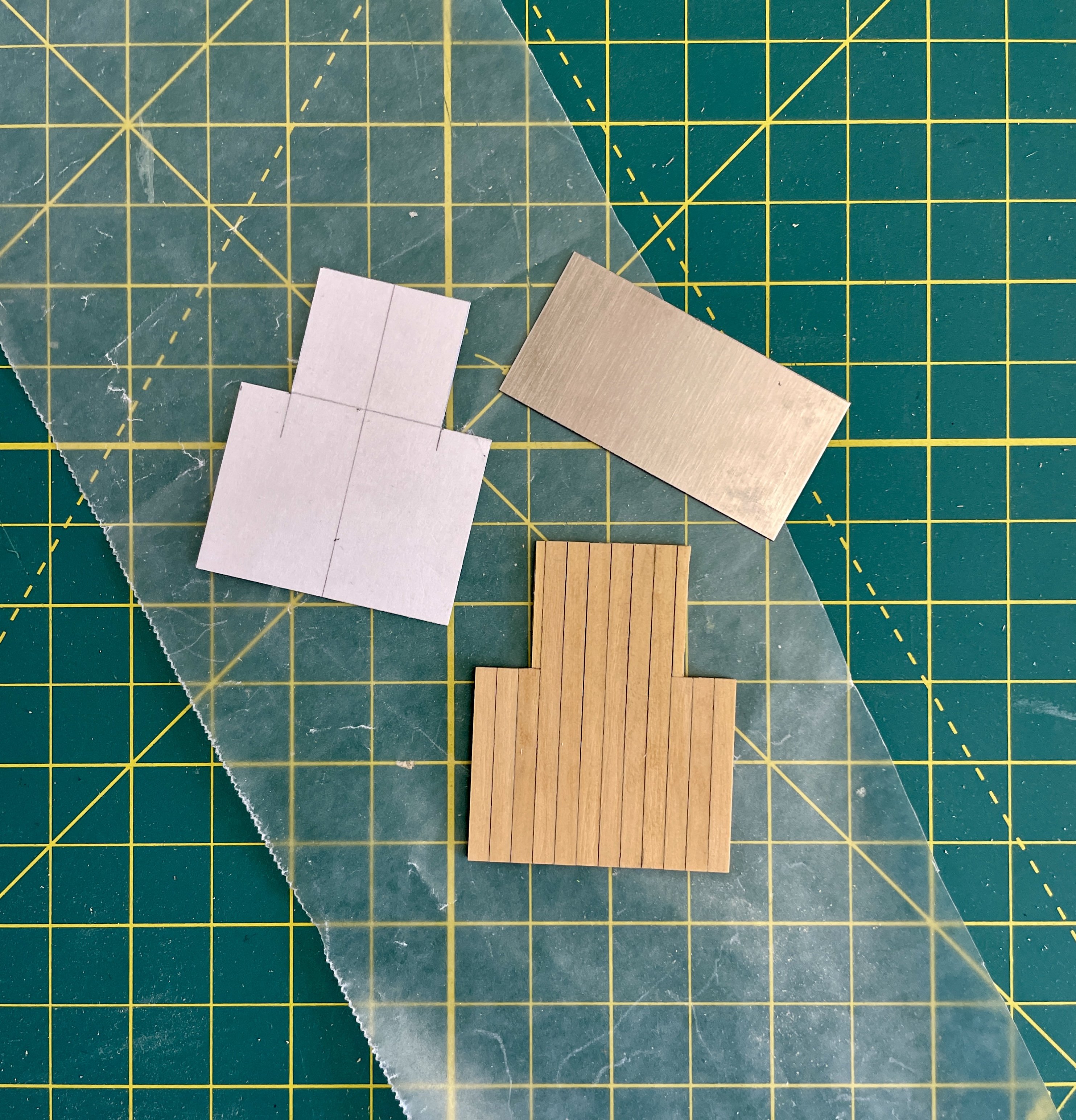
I took dimensions off the aft end of part 19 between BHs 9 and 10 and used those dimensions to make a cardstock template. I then traced the cardstock template outline onto a piece of birch plywood and then planked over the plywood with boxwood deck strips. After scraping and clear coating (matte), I then glued the boxwood planking to the aft end of part 19.

Cheers,
Jay
-
Deck Layout / Hull Modifications Pt 2
Before I glued the BHs to the false keel, I checked the camber radius of a couple BHs with radius curves. I came up with a 26 degree radius for the deck camber. I marked and cut that radius, along with also marking and cutting a 24 degree radius, in some scrap. I’ll use the 26 degree radius as a sanding template and the 24 degree radius as a bending template (the 2extra degrees is to help compensate for wood spring back).
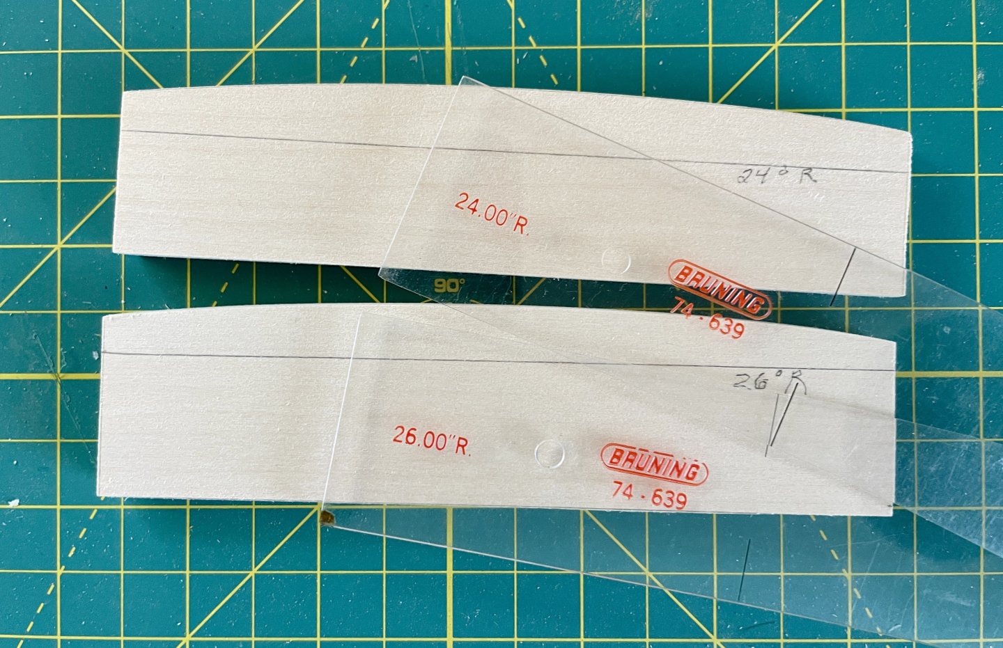
I then cut strips of thin birch plywood, wet bent it, and then let it dry on my 24 degree radius template. Once the strips were dry, I glued them over various cutouts on the underside of the subdeck.
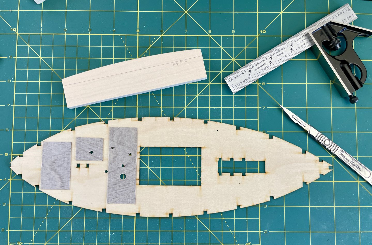
I then hand-drilled starter holes in the subdeck that corresponded to Vine’s additional fittings and alternative fittings positions. The mizzen mast hole was drilled to size. I then cut out an undersized hole where the warp room hatch will be located.
Cheers,
Jay
- Ryland Craze and GrandpaPhil
-
2
-
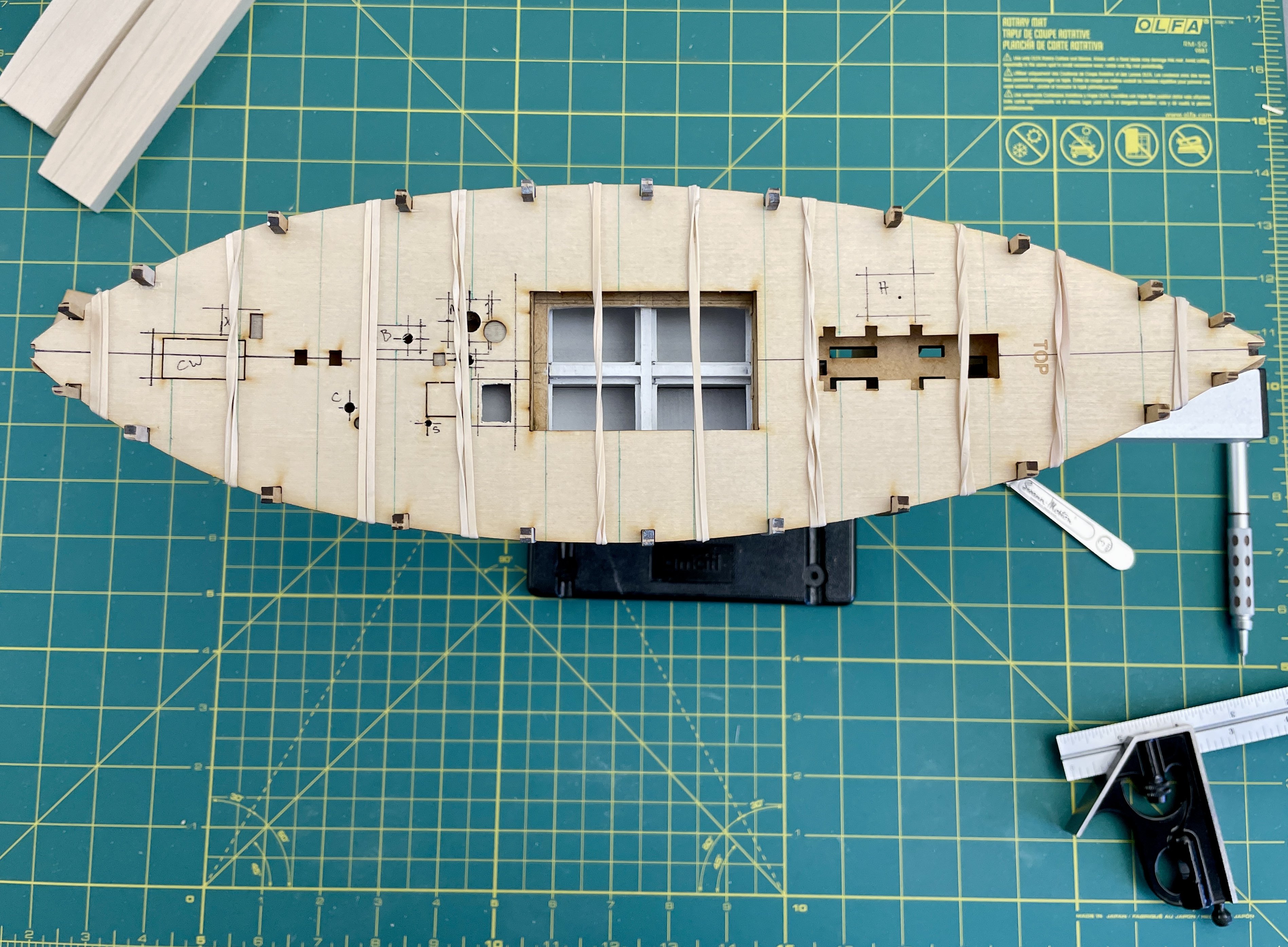
Deck Layout / Hull Modifications Pt 1
The purposes of my deck layout and hull modifications were to accommodate the Vine’s additional fittings, alternative fittings positions, and the fish hold’s alterations.
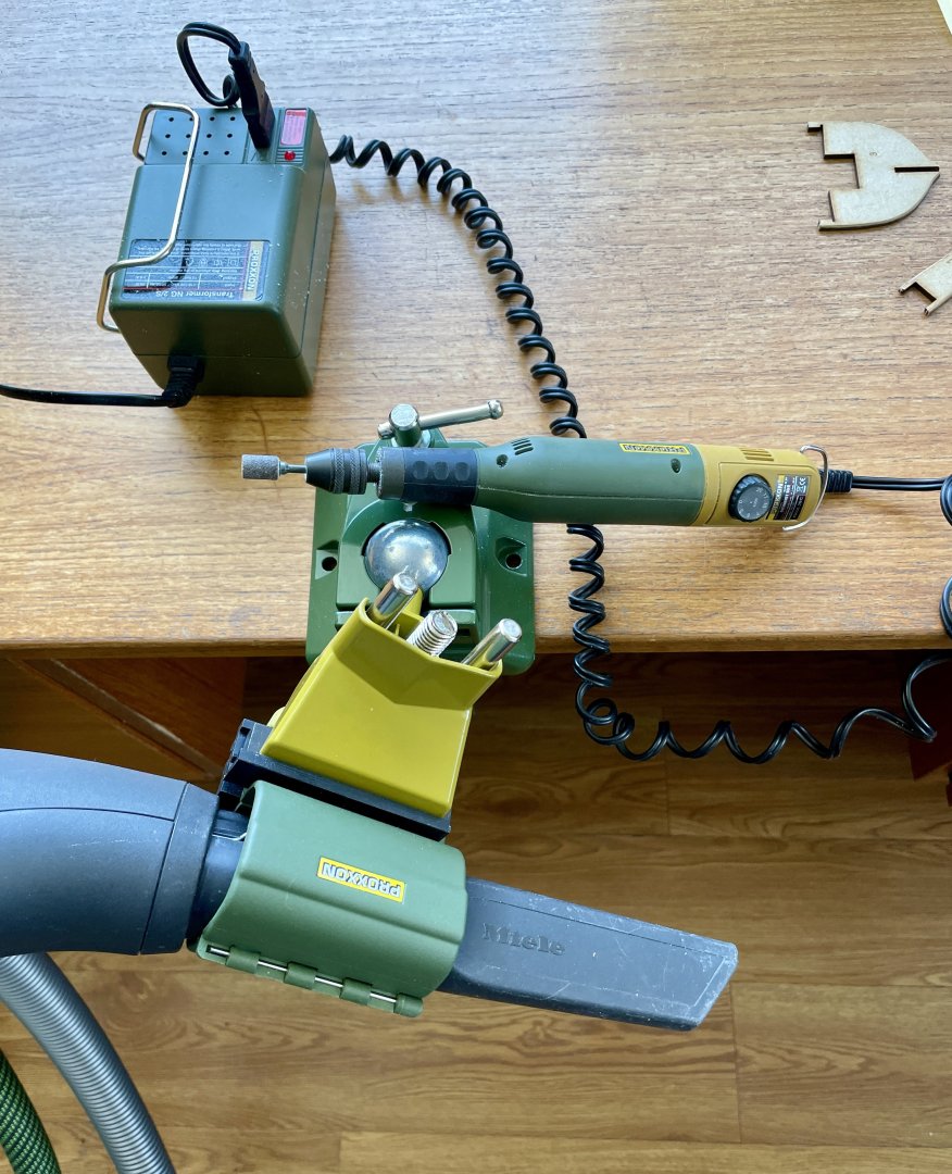
I first beveled all the BHs and infill pieces with my Proxxon rotary tool (on its slowest speed). I cobbled together a makeshift dust extractor while I did my beveling (finally found a use for Proxxon’s rotary tool holder….lol).
I then cutoff a top portion of the false keel between BHs 9 and 10 (more on this in Hull Mods Pt 3 below), and then glued all the BHs to the false keel.
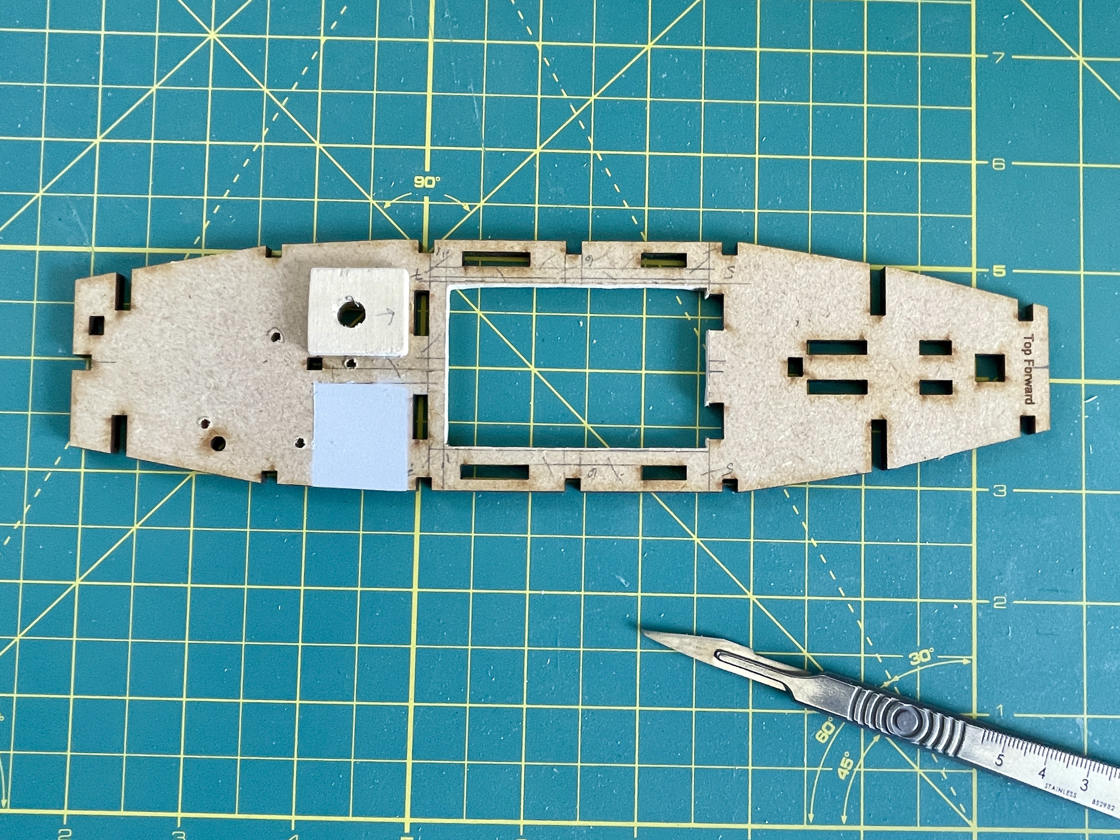
Parts 18 and 19 were then glued into place. You can see in image below where the warp room area was painted on part 19.
Cheers,
Jay
- Ryland Craze, BobG, GrandpaPhil and 1 other
-
4
-
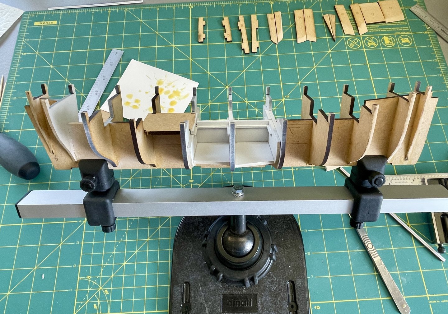
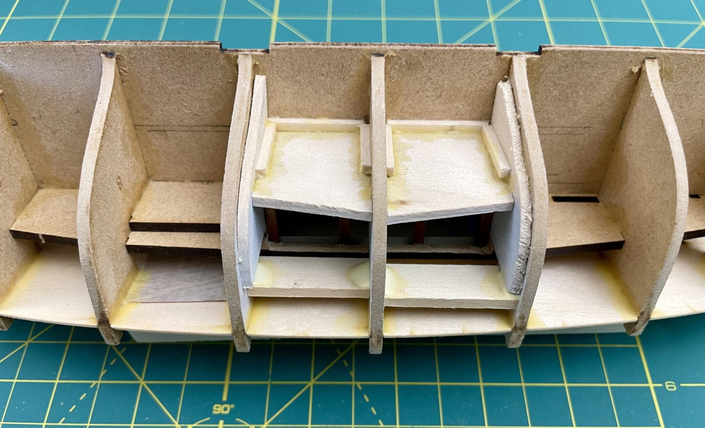
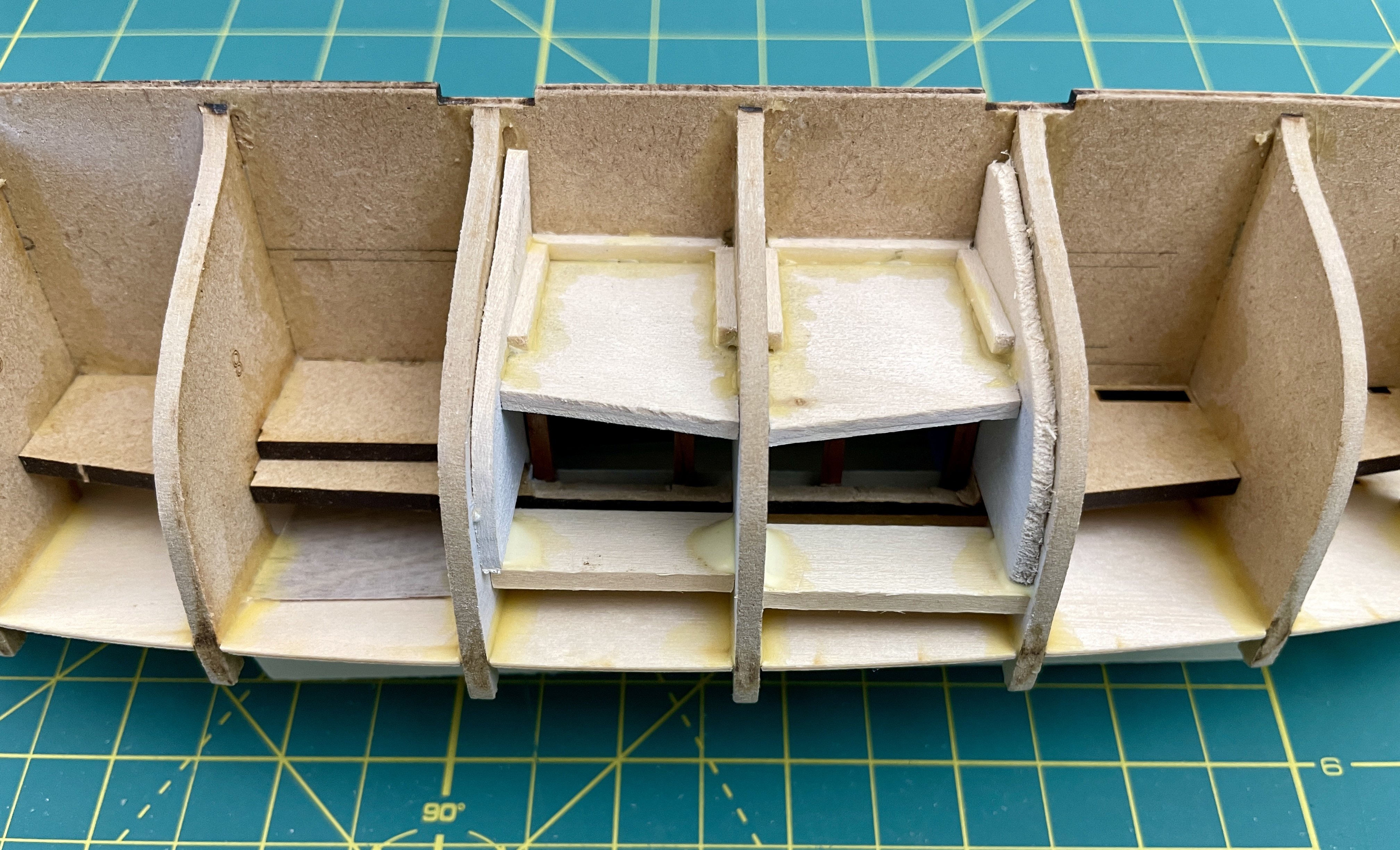
Fish Hold Modifications Pt 3
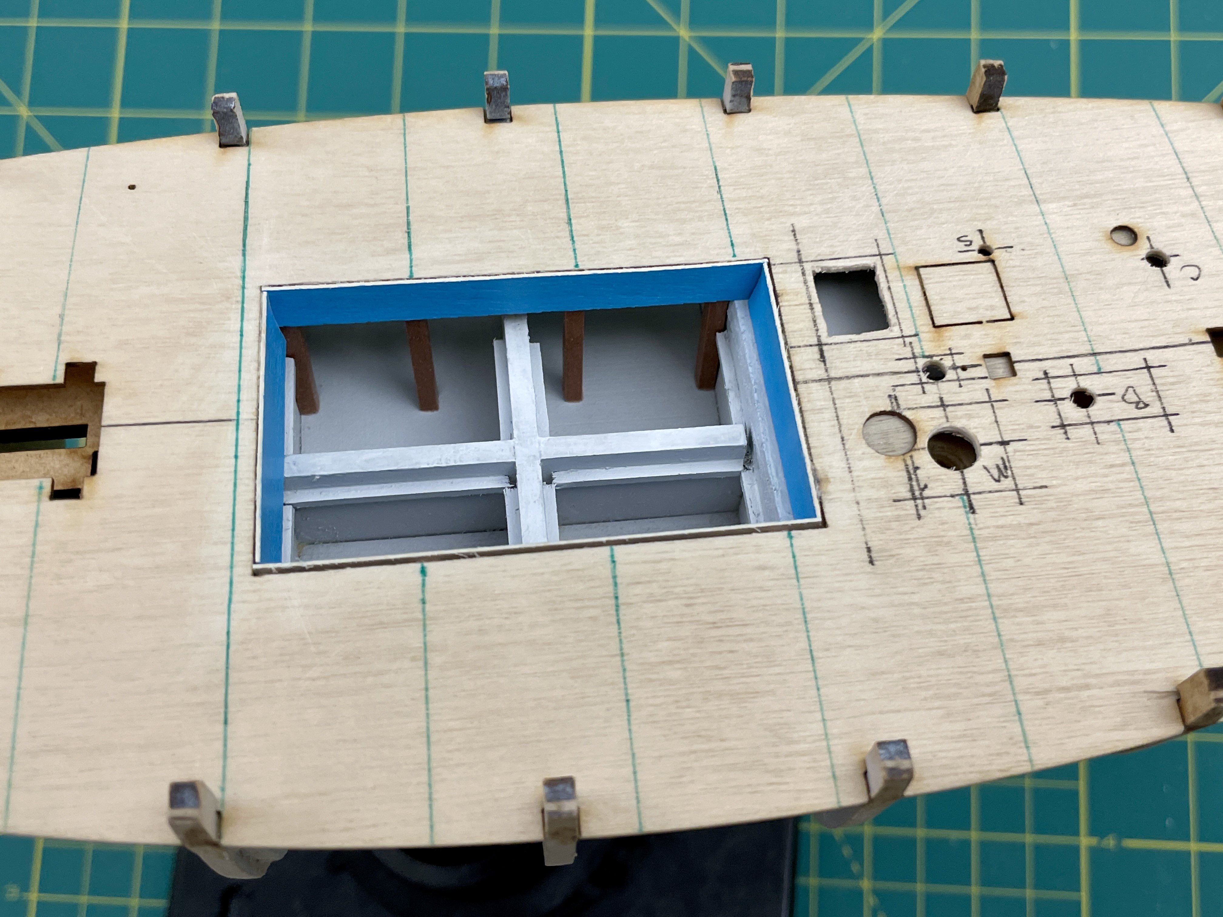
I then painted the fish hold area, and also BHs 9 and 10, light grey (Mr. Color 97). I used light grey because white paint usually looks grey in dim lighting. I painted the top edges of the fish hold flat white (Mr. Color 62) because those areas would receive more direct light than the hold further below.
As mentioned earlier, the fish hold and deck layout / hull modifications were done in tandem so what follows next will appear like I’ve skipped a few things; however, those gaps are covered in my deck layout / hull modification posts.
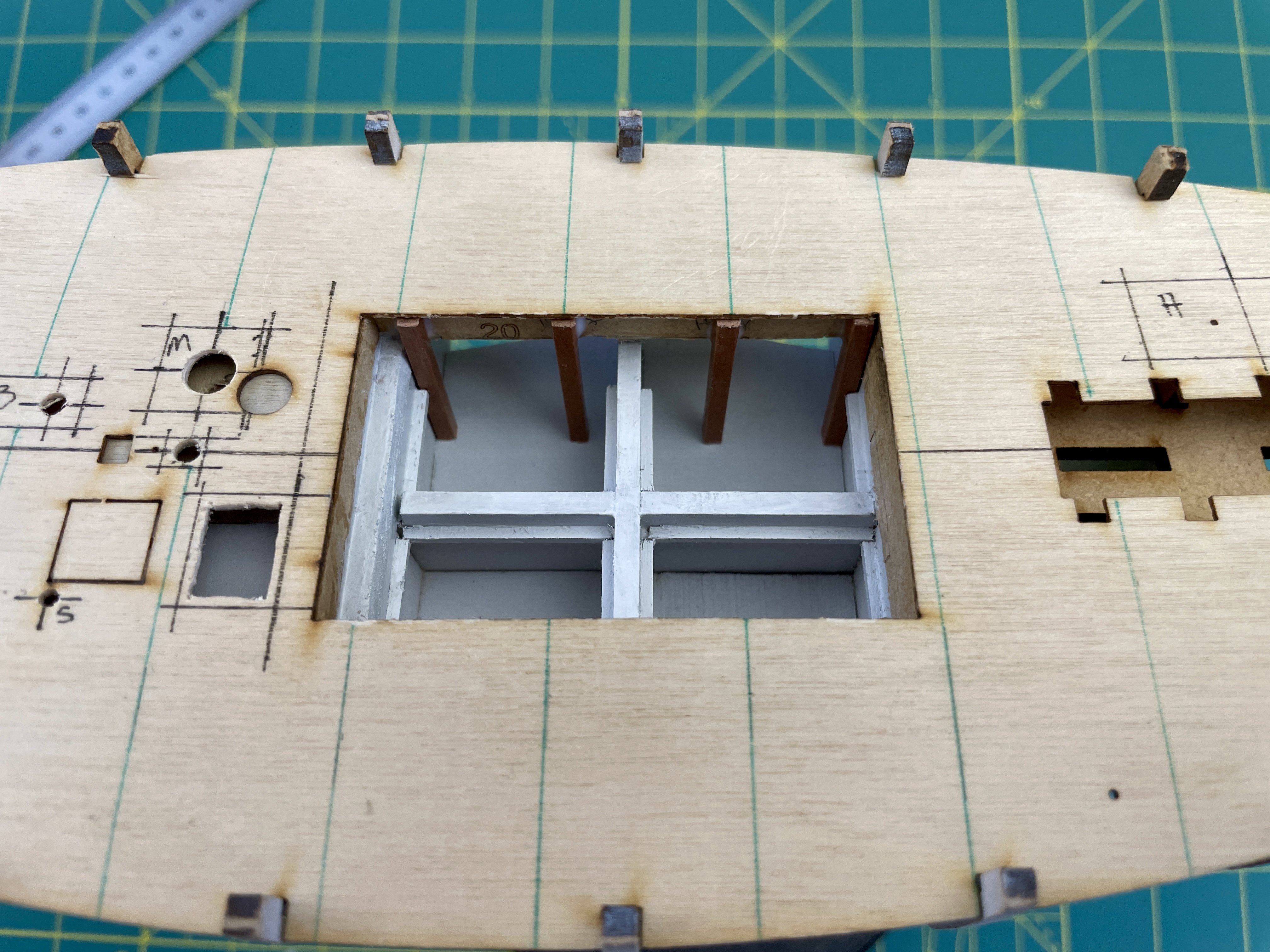
After the subdeck was installed, I undercut part 19’s MDF until it wasn’t fully visible below the two part 20 pieces. I then installed 8 3mm shellacked pearwood stanchions in the fish hold. The fore and aft stanchions on each side of the hold don’t fall under green deck beam lines because that’s where BHs 5 and 7 are located.
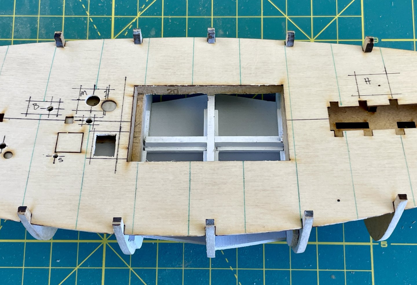

I then installed painted veneer (Mr. Color 323) on all 4 sides of the fish hold and then sanded the tops of the veneer flush with the subdeck.

The last item of the fish hold modification was installing bracing blocks to additionally compensate for the cutout I made in part 19.
Successfully completing the fish hold modifications without trashing the integrity of the model was a milestone!
Cheers,
Jay
-
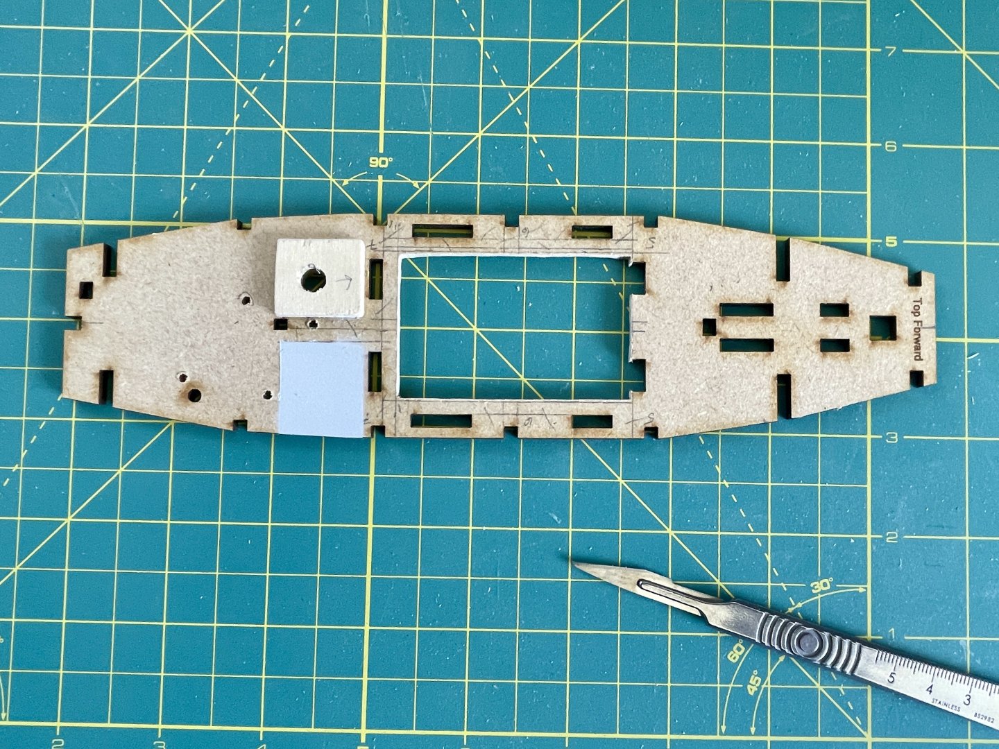
Fish Hold Modifications Pt 2
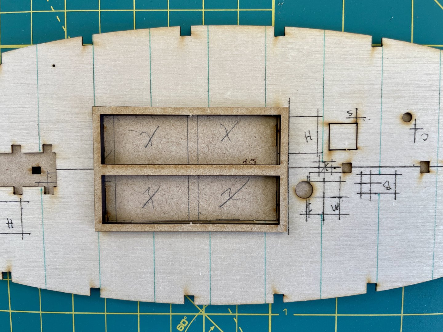
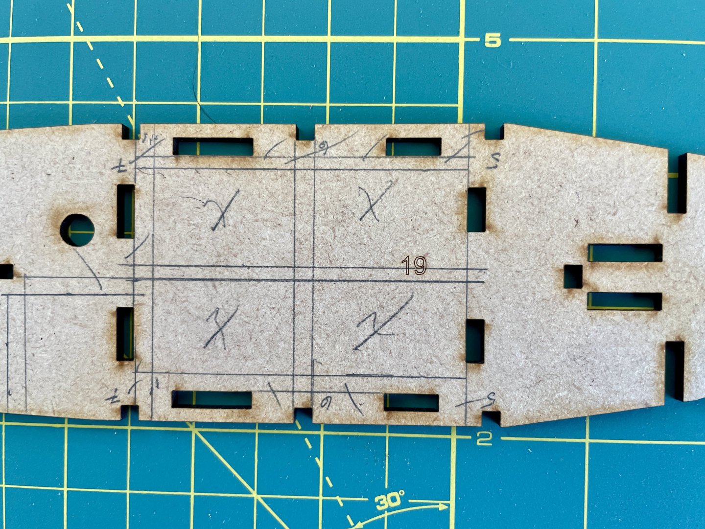
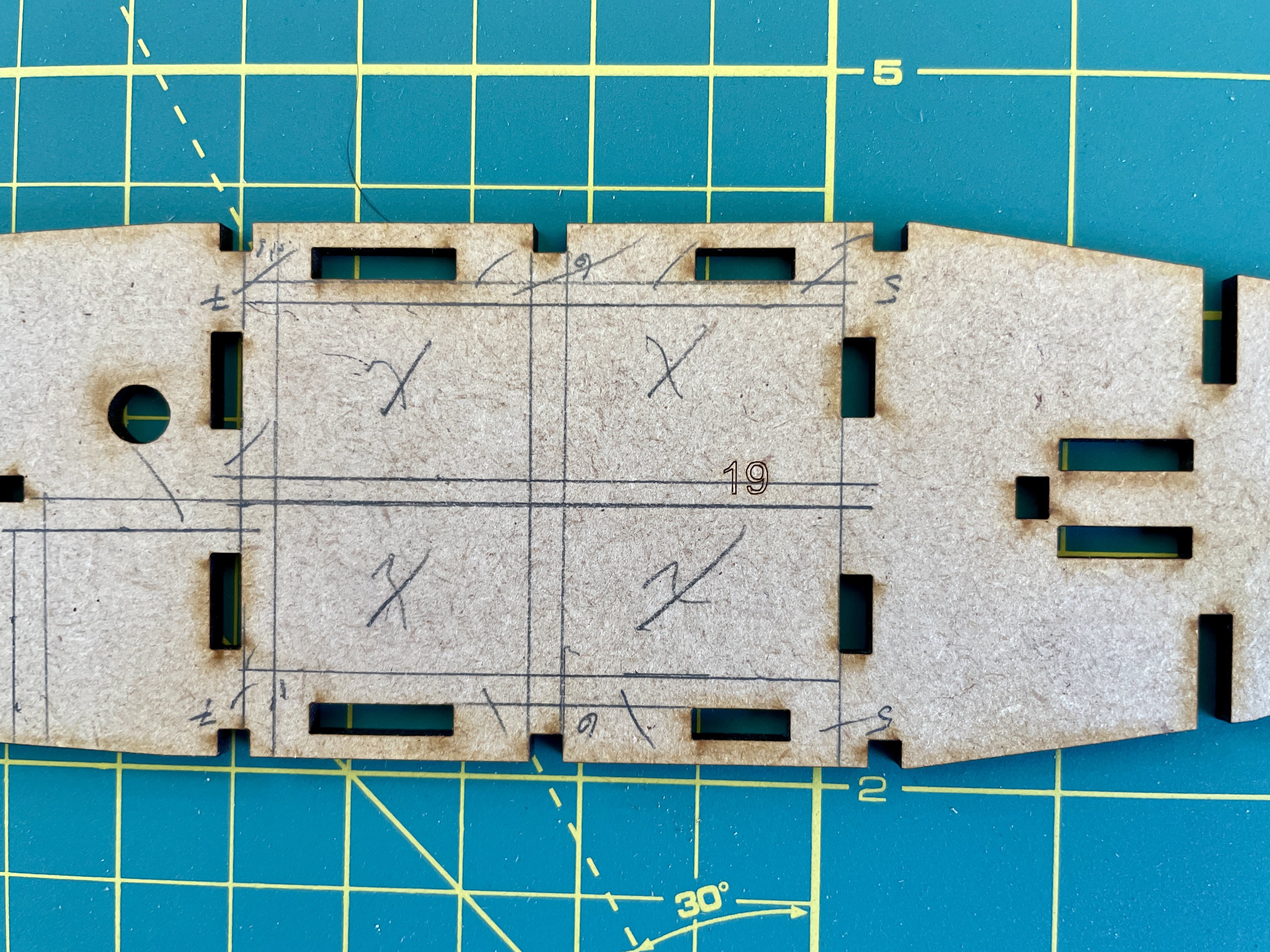
I then hand-drilled starter holes into part 19 that correspond to Vine’s subdeck additional fittings and alternative fittings positions.
While not visible, I reinforced the underside of part 19 at its original mizzen mast hole before I hand drilled the mizzen mast’s new position. I also reinforced the top of the new mizzen mast hole with an additional drilled support. Both holes are slightly ovoidal fore and aft to allow for raking the mizzen mast when it’s installed.
The pencil lined ½ square starboard of the mizzen mast support is about where the warp room hatch will open to, so this area will be painted.

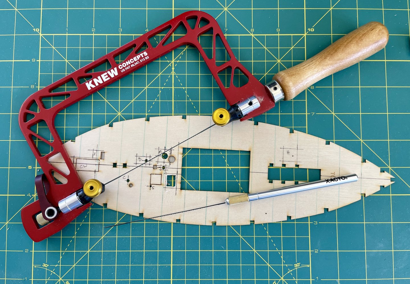
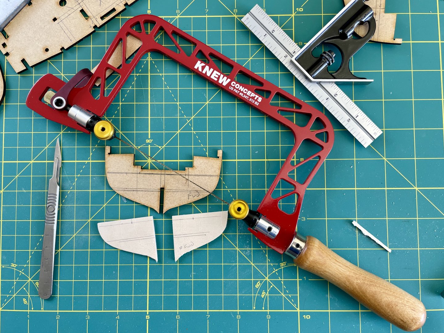
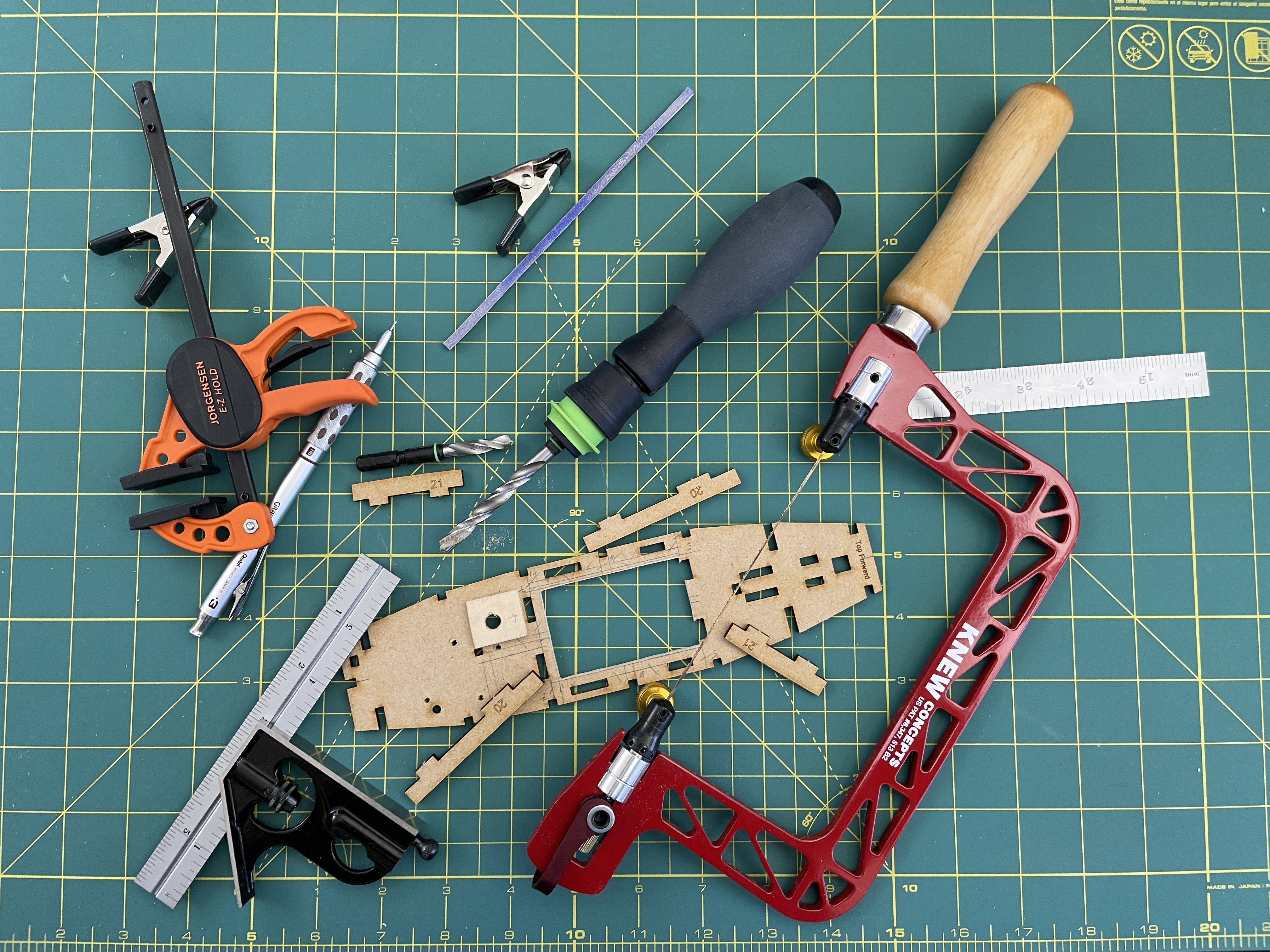
I then used a fret saw to cut out the X’d areas of part 19 to deepen the fish hold. I left about a 1/4 inch / ~ 6mm of meat on the port and starboard sides of part 19 to help keep it from possibly breaking.
I then began added the upper and lower supports framing to BHs 5, 6, 7, and the false keel; I also glued bracing inserts atop the lower framing supports.
Cheers,
Jay
-
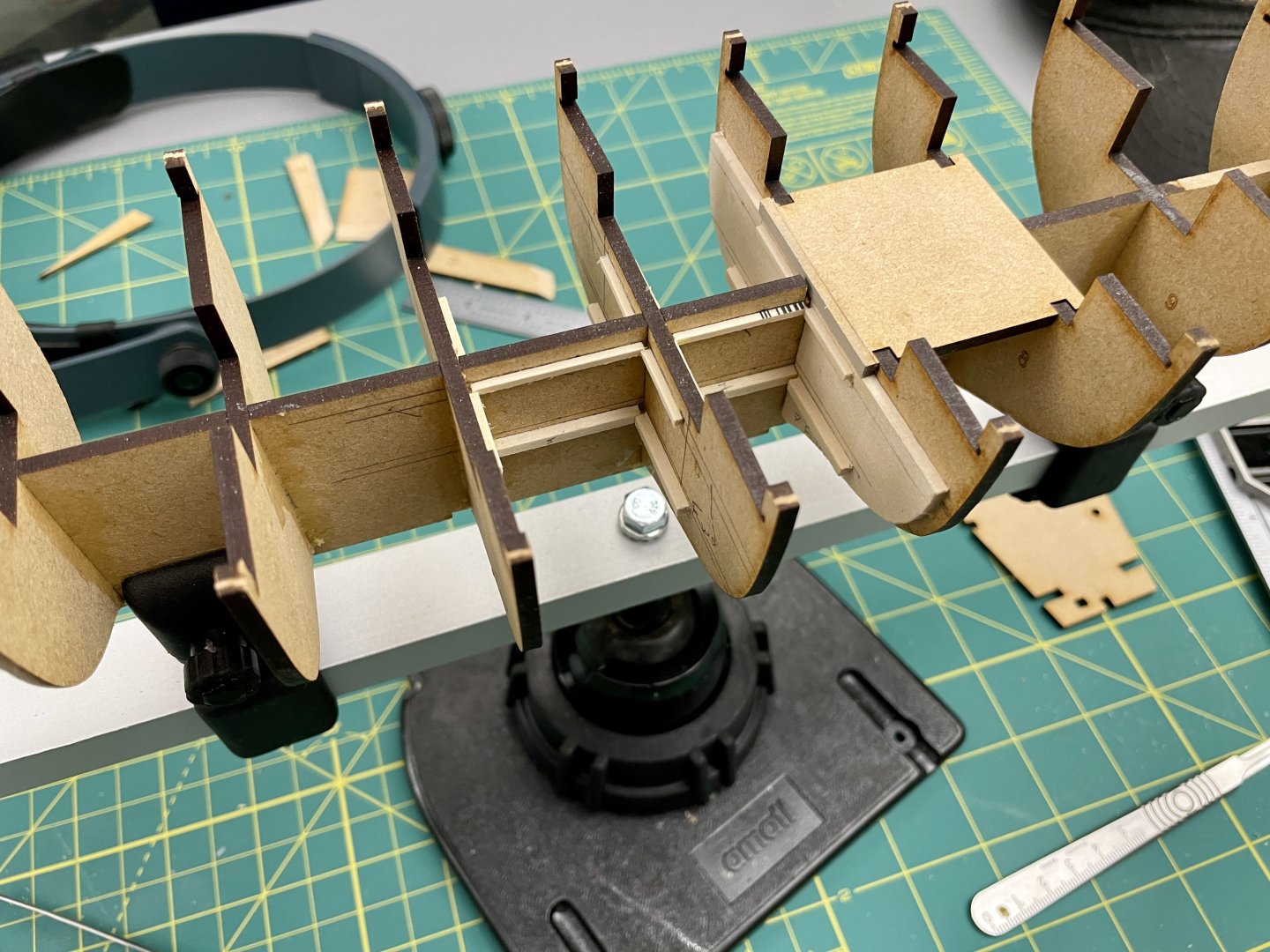
Fish Hold Modifications Pt 1
My purpose for modifying the fish hold depth was to add interesting detail to the model.
I began the fish hold modifications by using a height gage to mark positions for fish net platform supports. Because I didn’t have a sense of the model’s rigidity and etc. at this point, I didn’t want to alter bulkhead (BH) 6 or the false keel to the point where I would potentially compromise the hull form or structural integrity of the kit.
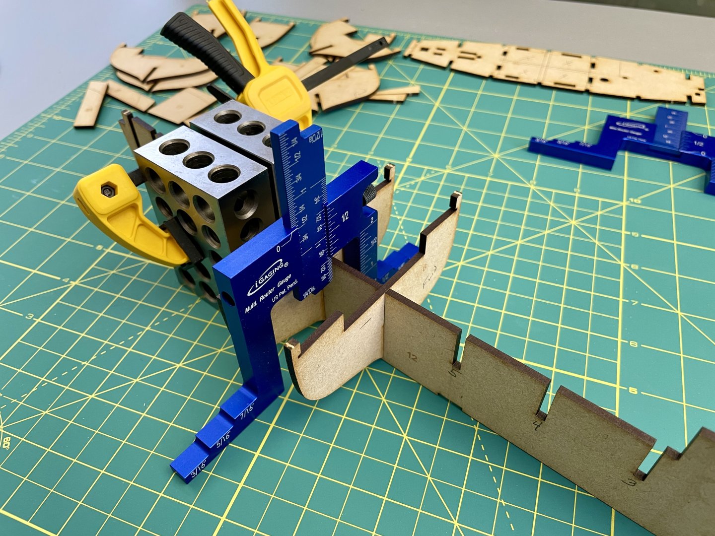
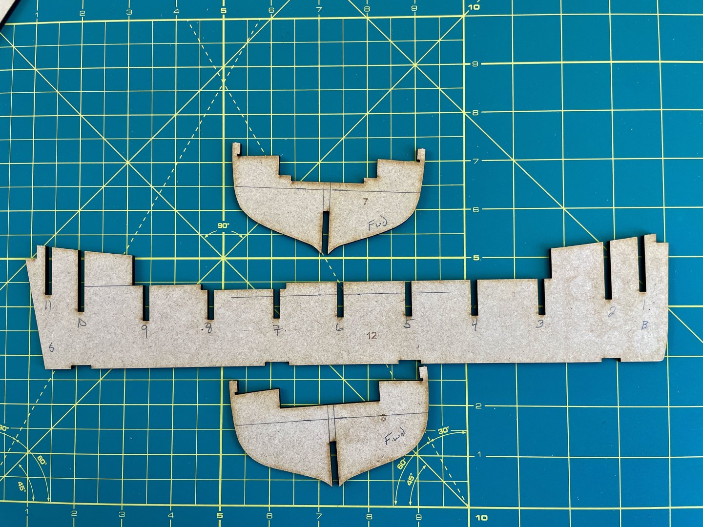
My decision on the heights of the net platform supports was a balance of getting a net to fit in the hold, hide the false keel and BH 6, and yet also be able to position the net so portions of the hold depth and etc. are visible. These platform supports largely won’t be visible, esp. along the false keel, once netting is added to the hold.
I then laid the fish hold frame (part 22) on top of the subdeck that in turn was laid over part 19 (it’s kind of sub-subdeck). The purpose here was to mark where I would make my initial cut outs in part 19 to deepen the fish hold.
I then marked positions for lower supports onto BHs 5, 6, and 7. The purpose for these lower supports is hold bracing inserts that should help compensate for the weakening of part 19 due to its cutouts. The bracing inserts will also serve as platforms onto which stanchions will be glued.
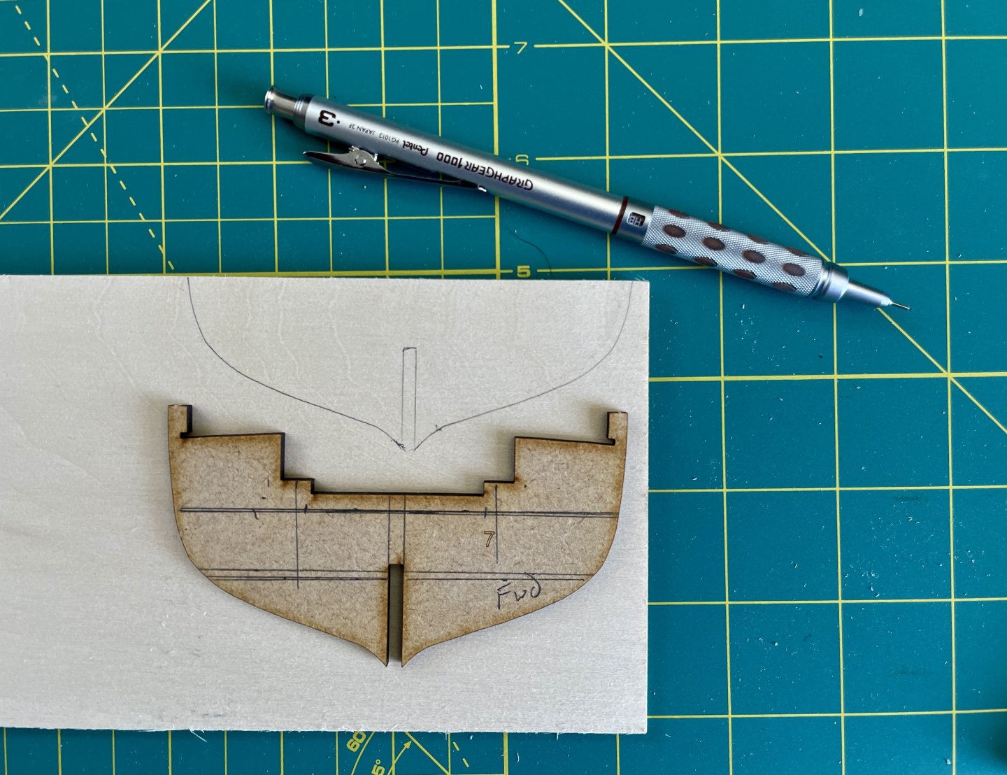
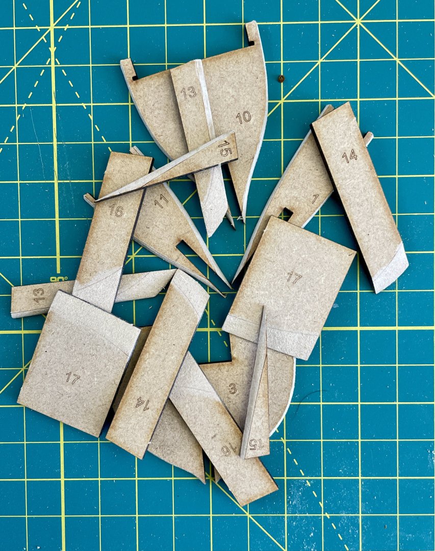
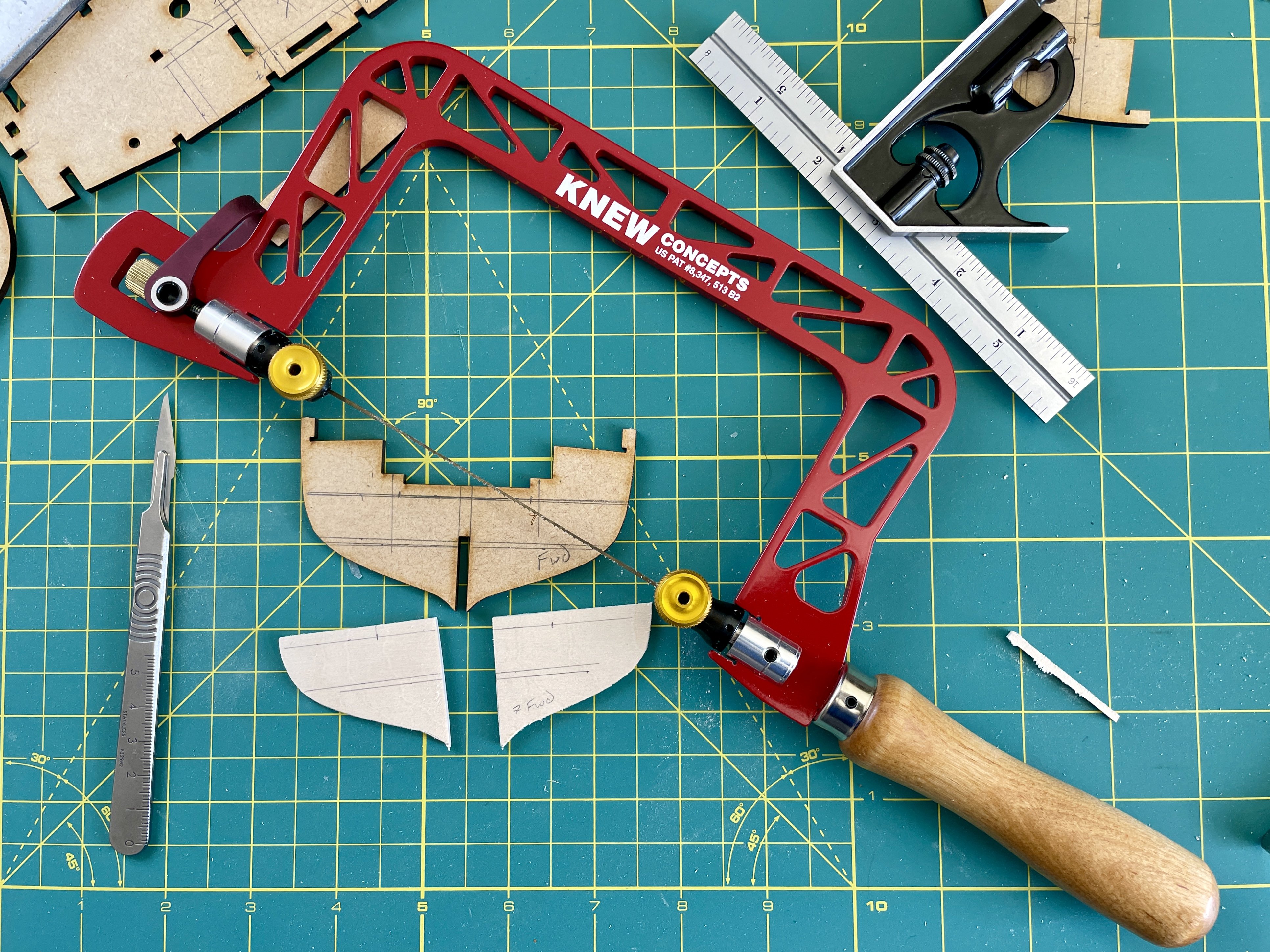
I also traced the outlines of BHs 5 and 7 onto basswood and then cut out those traced BHs. These BH cutouts were then glued to BHs 5 and 7 so that the fore and aft sides of the fish hold aligned with the fish hold subdeck cutout.
Cheers,
Jay
- yvesvidal, GrandpaPhil, Ryland Craze and 1 other
-
4
-
Fish Hold and Deck Layout / Hull Modifications
I decided to not post my log until after I successfully completed modifications I made to the fish hold and deck layout / hull. Clearly since I’m posting my log now, everything turned out okay but I didn’t know that when I started building. Essentially I didn’t want to start a log and then abandon both it and the build because my mods turned out to be trainwrecks!
The next several posts describe the mods I made, and although I’m posting the fish hold and then deck layout / hull mods separately, all the modifications I made had to be done in tandem with one another and progression of the build.
Cheers,
Jay
-
Build Adaptations
I mentioned in my comparison of the RMG and Beale “True Vine” models above that my intent was not to be critical of either build; indeed, I have no room to throw stones at either model since my model will also deviate from Oke and Marsh’s Vine plans.
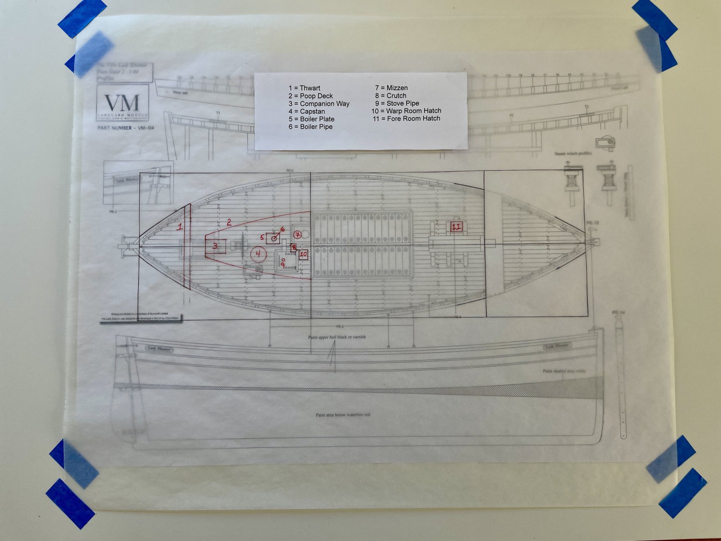
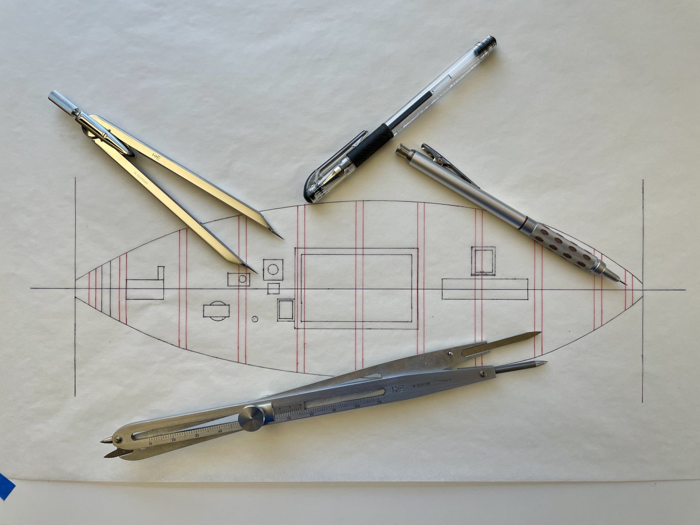
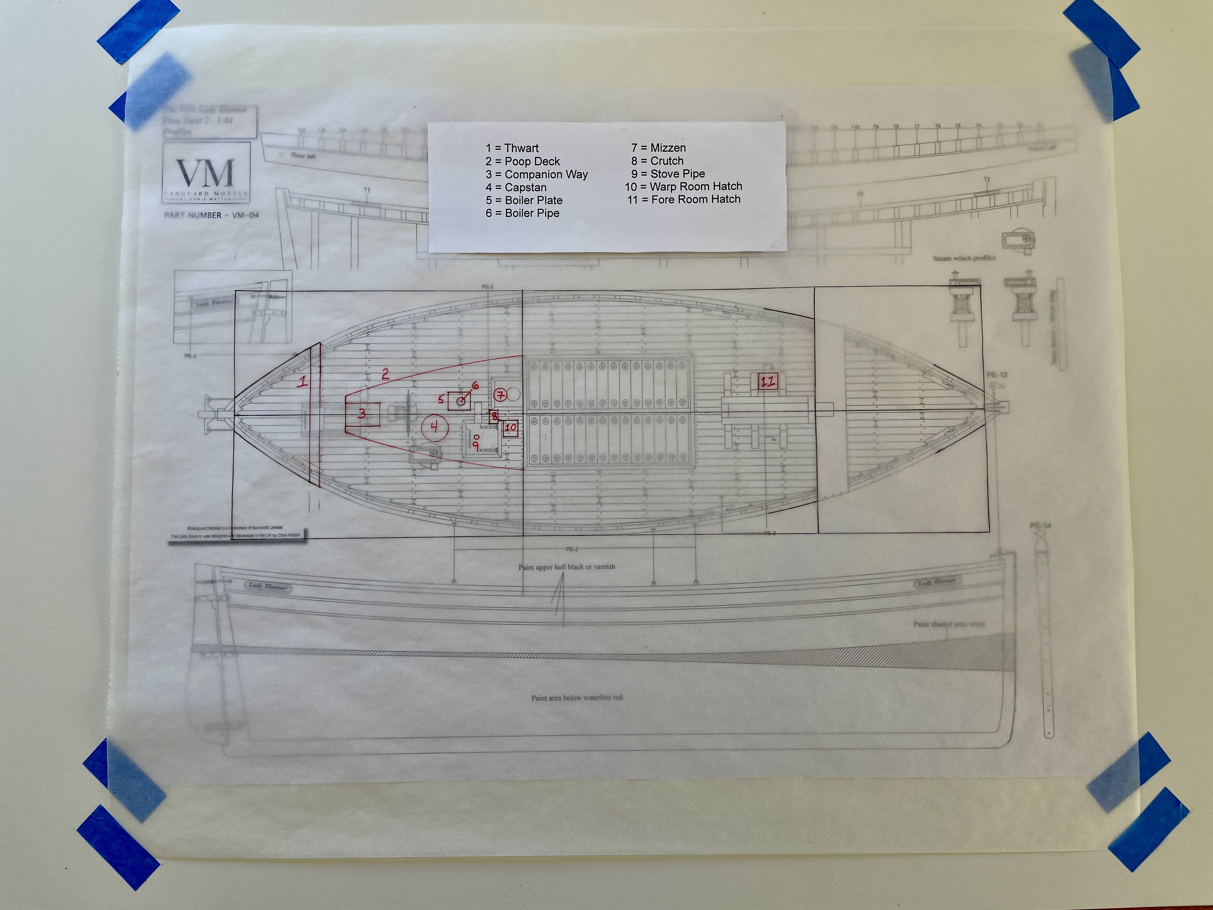
To see how much I could adapt the Vine to Eleanor, I 1st prepared the below quick-and-dirty overlay of the Vine’s key features onto Elanor’s deck plan. This was relatively painless using a pair of proportional dividers because the Vine’s scale is 1:32 (3/8” to the foot) and Eleanor’s scale is 1:64 (3/16” to the foot) and thus works out to a straightforward 1:2 ratio.
A feature of the Vine that I went back and forth over during my research is her poop deck. Ultimately what persuaded me to not include it were a passage from Marsh, contemporary photos, and finally what was esthetically appealing to my eye.
When Oke took off the Vine’s lines in 1936, she had already had undergone considerable alterations to include having been fitted with a motor (Marsh, “Drifters” 271). Marsh infers the poop deck may have been fitted onto the Vine after she had a wheelhouse fitted, along with other major alterations, when her motor was installed well after she was built in 1905 (“Drifters” 271). Although a poop deck / deck superstructure is a common feature of Zulus, I found no similar examples on any Fifies during my research. Indeed, the Vine’s poop deck is strikingly similar to the circa 1905 Zulu that Marsh discusses on page 265 and also provides a photo of (“Drifters” plate 173).
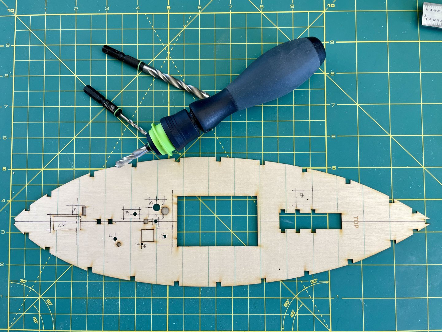
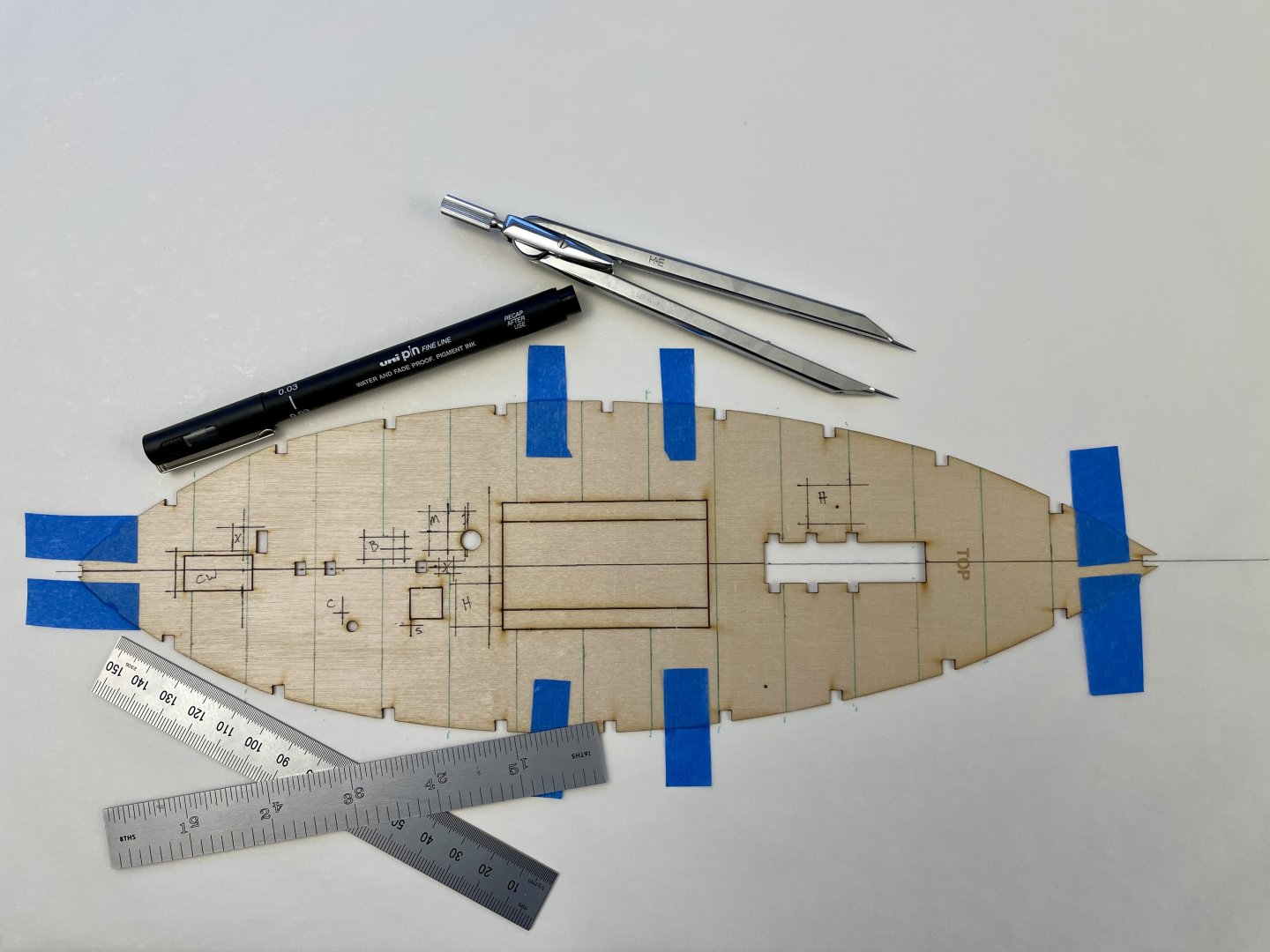
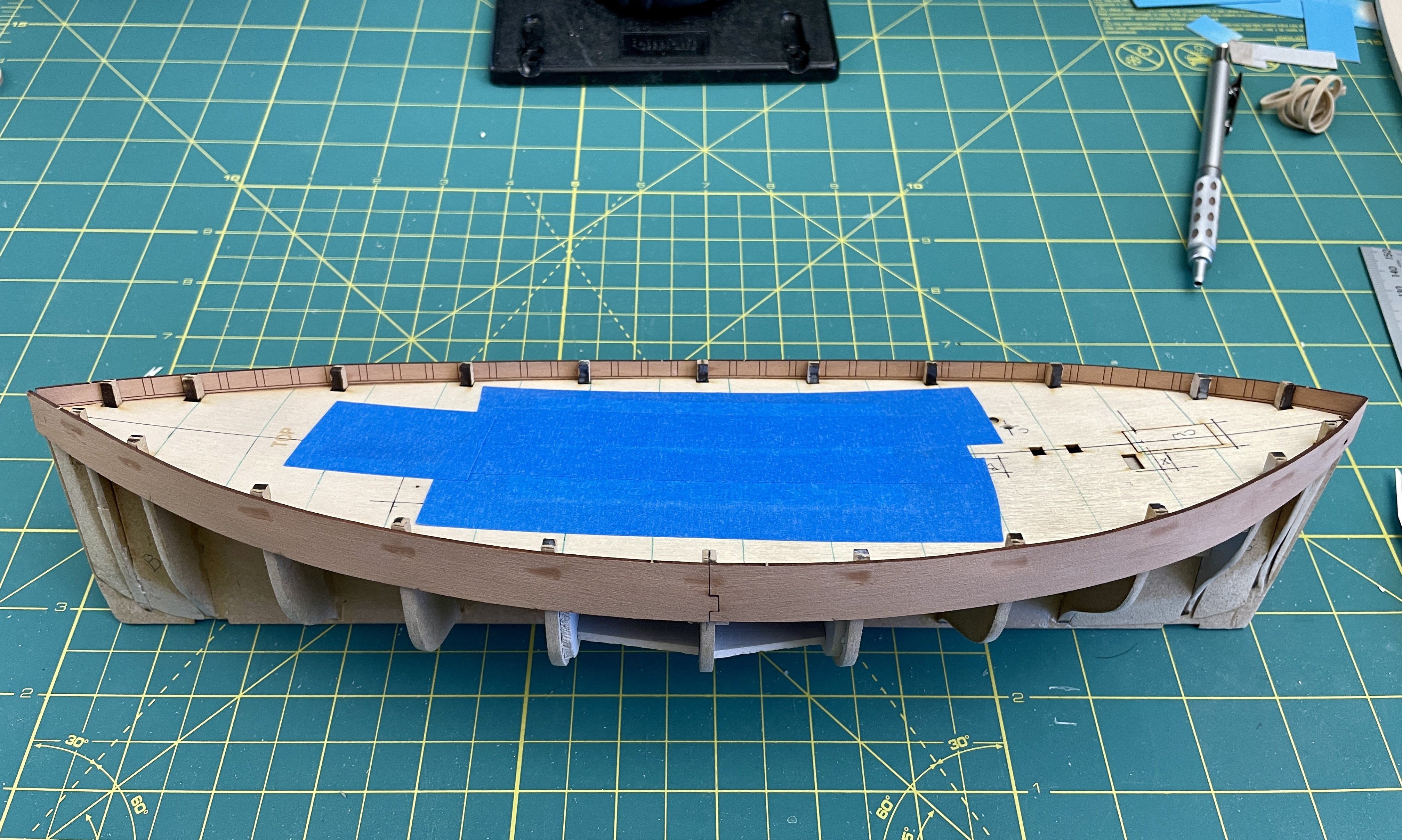
After reaching my decision about Vine’s poop deck, I then created a series of drawing layers (an old school version of Photoshop…LOL) using the kit’s plain subdeck .
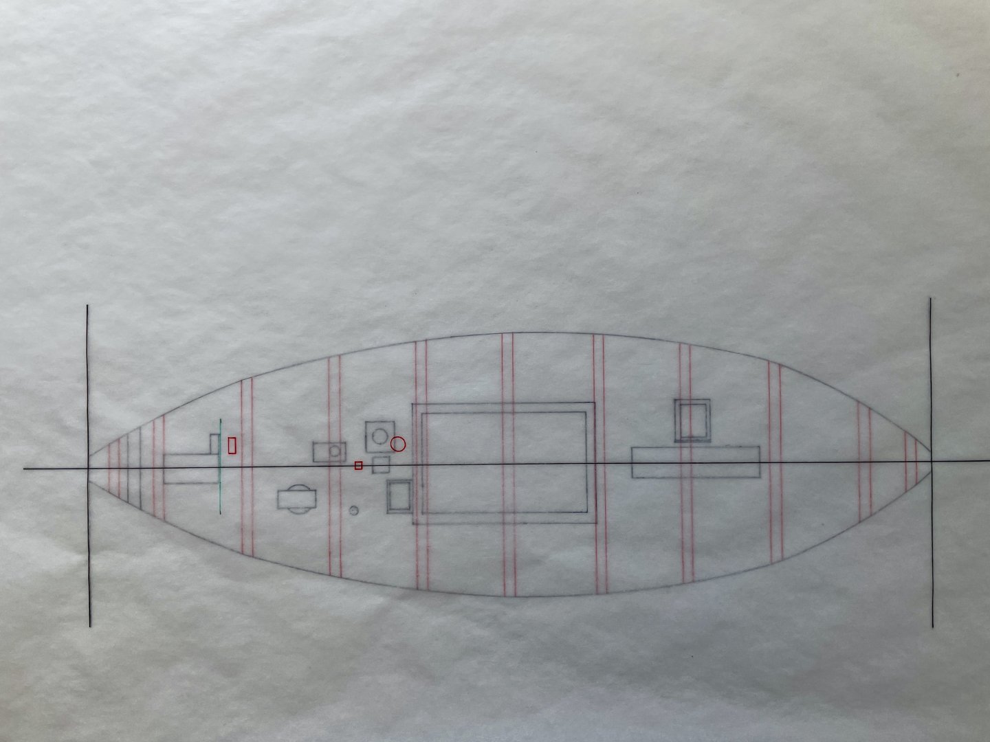
The purpose of the 1st layer drawing was to get a sense of where the Vine’s deck fittings were in relationship to Eleanor’s fittings and to also get a sense for how additional modifications that I want to make will align with respect to Eleanor’s keel and bulkhead framing. In case someone’s reading this, I inked in the wrong lines of the fore room hatch on this layer, so it’s proportions are a wee bit off….
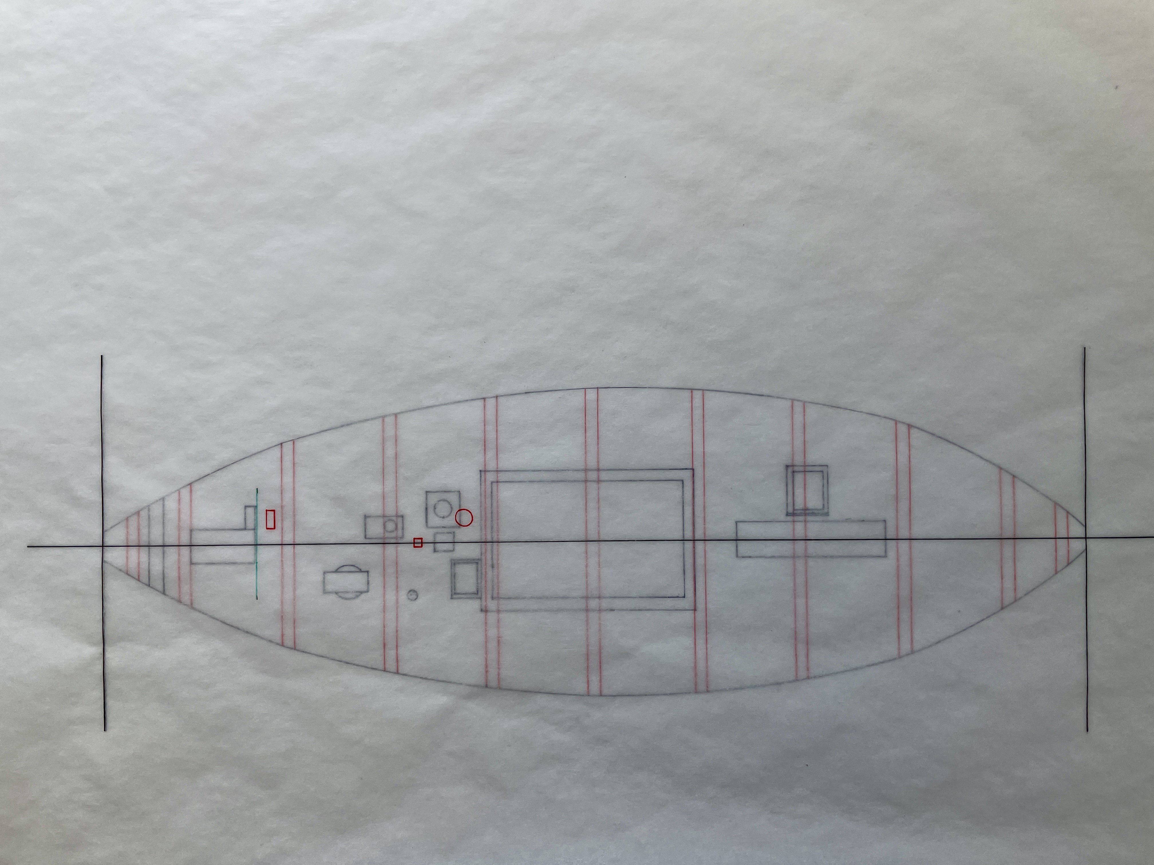
The purpose of the 2nd layer was to see were and how changes I’ll make will impact part 19 in the kit, which I’ll go into when I start building.
The purpose of the 3rd layer was to get an idea of where the Vine’s deck fittings will land with respect to the boat’s deck planking. Essentially I want to avoid having splinters for deck planks because of deck fittings placement. While I won’t 100% know how the deck planking will work in relation to deck fittings until I actually start planking the deck, I did make few slight placement changes at this stage to align with my deck plank sizes and approximately where they’ll land on the deck. Also I fixed the proportions of the fore room deck hatch on this layer.
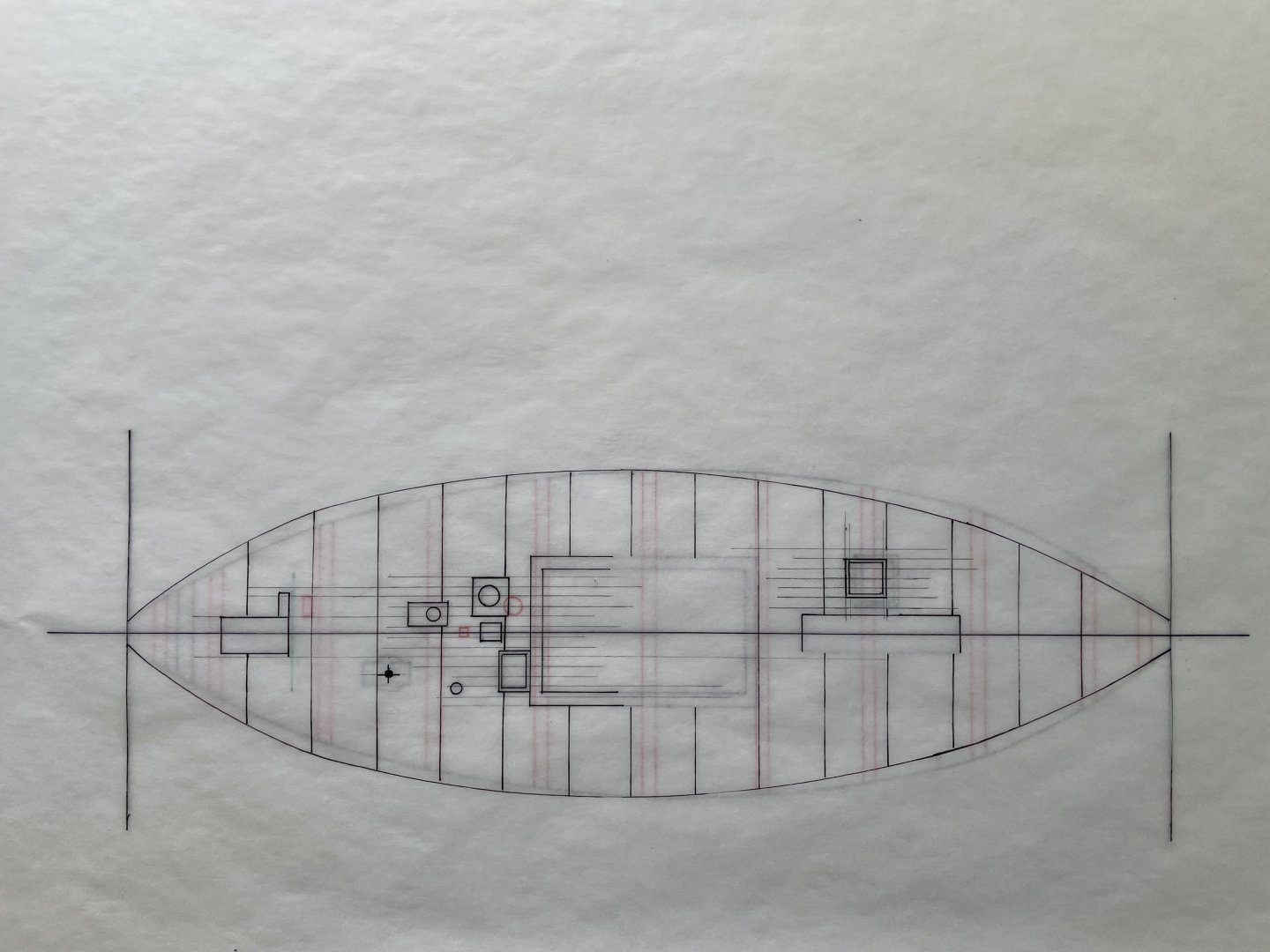
The keen observer will notice the deck outline on the 3rd layer slightly differs from the deck outline on the 1st layer…. I used the printed maple deck to draw the outlines on the 1st and 3rd layers. However, because the printed deck really curls upward, I flipped this deck over to its unprinted side to compensate for its curl. When I inked deck outline on the 1st layer, I didn’t notice I had reversed the bow and stern ends of the printed deck when I flipped it over. Although my goof didn’t impact deck fittings positions, it did give me a laugh when I caught the mistake when I started working on the 3rd layer drawing.
After I finished the 3rd layer drawing, I then transferred that layer’s deck fitting positions onto the kit’s subdeck. The green lines on the subdeck mark deck beam positions taken from the kit’s printed maple deck, and I’ll use these lines as rough guides when it comes time to figure out the deck’s butt shifts.
Cheers,
Jay
-
“True Vine” Models
Although I may sound critical with my assessment that follows of the RMG and Beale “True Vine” models, that’s absolutely not my intent. My intent here was only to describe how each model significantly differs from the Vine’s plans.
The Royal Museums Greenwich (RMG) model of the “True Vine” in its collection and Tom Beale’s model (see Will Taylor reference entry) of her can hopefully give one a sense of her Oke and Marsh plans.
Of the 2 models, Beale’s version is closer to Oke and Marsh’s plans than is the RMG version. However, the RMG lists no information about when its model was built or who its builder was, so it’s possible the RMG model was built off different plans than Oke and Marsh’s.
The thwarts just aft of the midships on the RMG version are not in Oke and Marsh’s plans; also, this model version appears to not have a warp room hatch. I will discuss later in my log the nets on model’s port side.
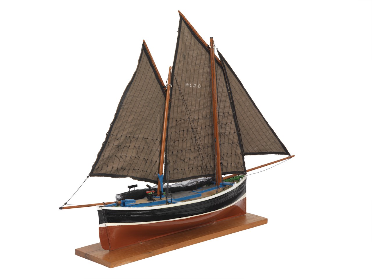
Source: RMG, www.rmg.co.uk/collections/objects/rmgc-object-68796.
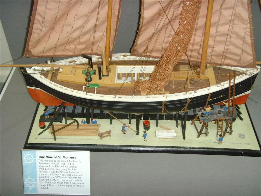
Beale’s worm drive mechanism at the stern of his model doesn’t align with the Vine’s plans. I’ll go into more detail about the Vine’s worm drive when I reach that point in my build. Also while the knees on the starboard side of the tabernacle on Beale’s model are not in Oke and Marsh’s plans, I think their addition by Beale was a misinterpretation of Marsh.
In “Sailing Drifters” page 271, Marsh describes the Vine’s foremast as being stepped into a tabernacle with “side bridges.” Earlier on page 249, Marsh discusses the “Gratitude” and describes how its foremast is also stepped into a tabernacle with “bridges.” However in addition to his description, Marsh also includes a drawing of the foremast tabernacle (figure 64) that is without knees and then further directs the reader to plate 152, which is a photograph of the forward end of the “Gratitude” and clearly shows the vessel’s tabernacle which does not have knees.
Until I read page 249 and studied the accompanying figure and plate, I was also thrown by Marsh’s term “side bridges” and thought he may have meant knees but was confused because there aren’t any tabernacle knees depicted in the Vine plans. After I read page 249, and then looked back again at Vine’s plans, it became clear to me that Marsh’s “side bridges” term referred to a tabernacle’s framing versus being his term for tabernacle knee braces.
Beale’s choice to depict the Vine with sails set and nets draped from the mainmast while in drydock is interesting but likely was a stylistic choice—no stone throwing there because I’m going to include a few stylistic embellishments in my build, too.
Cheers,
Jay
- BobG, ccoyle, JacquesCousteau and 3 others
-
6
-
Notes & References
Notes
I’ll update my log reference list below as needed throughout my build.
For those considering building either Chris’ Fifie and or Zulu kits, or both kits, Marsh’s “Sailing Drifters” is an invaluable resource.
The SS Great Britain Trust holds the David McGregor ship plans collection; however, they do not have copy right permissions for Oke and Marsh’s “True Vine” plans, which are part of the McGregor collection, and thus cannot sell copies of those plans.
While fair dealing and fair use guidelines do allow for the use of copyrighted material for educational and scholastic purposes, applying those guidelines can be tricky. Given that the plan copy right permissions for the “True Vine” are in question, and the plans in Marsh’s “Sailing Drifters” are definitely copyrighted, I decided it was prudent to not post plan images on MSW.
Gordon Williams’ model of the “Muirneag” is an excellent source of detail from whom MSW’s Blue Ensign (BE, i.e., Maurice Wilcox below), and I have borrowed inspiration. Likewise, I have also borrowed inspiration from BE’s excellent “Lady Eleanor” and “Muirneag” builds.
The Scottish Fisheries Museum’s Fifie “Reaper” is an great source and resource. Also the surviving Fifie “Swan,” though not as well-known as the “Reaper,” is also a first-rate resource, though I did find fewer images of her than of “Reaper” during my web research.
References
“Cellardyke Sailing Fishing Boats.” The Cellardyke Trust, 15 Sept. 2023,
www.cellardyketrust.org/further-cellardyke-research/cellardyke-photos/cellardyke-sailing-drifters/.
“Collections.” SS Great Britain, 7 Feb. 2024,
www.ssgreatbritain.org/collections-and-research/collections/.
“Inflation Calculator.” Bank of England, 20 Mar. 2024,
www.bankofengland.co.uk/monetary-policy/inflation/inflation-calculator.
Marsh, Edgar J. “Inshore Craft of Britain: In the Day of Sail and Oar.” David & Charles, 1970. 2 vols.
Marsh, Edgar J., MSNR. “Sailing Drifters.” Percival Marshall & Co. Ltd., 1952.
Oke, Phillip J., and Edgar J. Marsh, MSNR. “‘“True Vine”’ ML20”. M/5A, M/5B, & M5/C. 1946. David McGregor Plans, 99 Lonsdale Road, London, S.W.13.
Owens, Peter. “Records of Fishing Vessels.” Crew List Index Project,
www.crewlist.org.uk/about/fishingvessels.
Pottinger, James A. “Fishing Boats of Scotland”. Tempus Publishing Ltd, 2005.
“Reaper.” Scottish Fisheries Museum- Reaper,
www.scotfishmuseum.org/reaper.php.
Smylie, Michael. “Traditional Fishing Boats of Britain & Ireland”. Waterline Books, 1999.
“Source 1: The Telegram, 15th October 1881.” The Eyemouth Fishing Disaster 1881,
www.scottisharchivesforschools.org/naturalscotland/eyemouthdisaster.asp.
“The Statutes of the United Kingdom of Great Britain and Ireland [1807-1868/69] : Great Britain : Free Download, Borrow, and Streaming.” Internet Archive, London, His Majesty’s statute and law printers, 1 Jan. 1970,
archive.org/details/statutesunitedk31britgoog/page/80/mode/2up?view=theater.
Taylor, Will. ““True Vine” ML 20 - Trawler & Ship Models - Gallery.” TrawlerPictures.Net, 10 March 2011,
www.trawlerpictures.net/gallery/image/34654-true-vine-ml-20/.
““True Vine”; Fishing Vessel; Lugger: Royal Museums Greenwich.” “True Vine”; Fishing Vessel; Lugger | Royal Museums Greenwich,
www.rmg.co.uk/collections/objects/rmgc-object-68796.
Wilcox, Maurice. “Lady Eleanor”by Blue Ensign - Finished - Vanguard Models - Scale 1:64.” Model Ship World, 20 May 2020,
modelshipworld.com/topic/24212-lady-eleanor-by-blue-ensign-finished-vanguard-models-scale-164/.
Wilcox, Maurice. “Muirneag 1903 by Blue Ensign – FINISHED - Vanguard Models – 1:64 scale - A Scottish Zulu Fishing Boat Based on the Vanguard Models Zulu Kit.” Model Ship World, 12 August 2020, https://modelshipworld.com/topic/25321-muirneag-1903-by-blue-ensign-–-finished-vanguard-models-164-scale-a-scottish-zulu-fishing-boat-based-on-the-vanguard-models-zulu-kit/.
William, Gordon. “Building the Model.” Muirneag SY486, 8 Feb. 2013,
www.muirneag.net/article.html.
Cheers,
Jay
-
“True Vine” Background
The Fifie “True Vine” was built in 1905 by Robertson Innes at St. Monance, East Neuk of Fife, Scotland (aka St. Monans, which is approx. 3 miles / 5 km south from Anstruther); however, in Oke and Marsh’s plans, the “True Vine” is as she appeared in 1928 (“‘“True Vine”’ ML20”). Her registration number was ML 20, and she was registered out of Methil (Owens, “Records”, Crewlist.org.uk).
The lines of the “True Vine” were initially started by Oke in 1936 but he was killed before he finished his draughts, and Marsh completed Oke’s plans in 1946. The plans consist of 3 sheets: (1) body, sheer, and half breadth profiles at 1:32 scale, (2) deck layout and a profile also at 1:32 scale, and (3) a sail plan at 1:60 scale (“True Vine”, RMG.co.uk).
While the final fate of the “True Vine” in unknown, her broken back indicates she led a hard, working life (Marsh, “Drifters” 272). A notable feature of Vine’s was her poop deck and was at about the same height as her 6” high fish hold. The poop deck was installed aft of the fish hold sometime from when she was built in 1905 to when Oke took off her lines in 1936 (Marsh, “Drifters” 271).
While I’ll likely post some dimensional information and other details about the “True Vine” in my log, for those interested, Marsh provides detailed information about her on pages 270 – 273 of his “Sailing Drifters” along with reduced-size copies of P.J. Oke’s and his plans on pages 348 – 351.
Cheers,
Jay


Ariel by Jay 1 – Vanguard Models – 1:64 - based on the True Vine 1905 using Lady Eleanor kit
in - Kit build logs for subjects built from 1901 - Present Day
Posted
Metal Work: Flues and Lantern
I worked on making fittings while waiting for more wood (see previous post). In the 1st pic below, I’m drilling out steel a steel boiler flue and in the 2nd pic, turning brass for a navigation lantern . The 3rd pic are my initial results along with the stock I used.
The lantern in the 4th pic is a test piece and is 4.5 mm at its widest and 8 mm high. While it’s not visible, I bored a 3 mm hole from the bottom of the stock so I can possibly later insert material for a lens.
The reason it’s a test piece is because I’m going to try to mill openings in the front and back for the lens whilst leaving 2 brass side pieces about 1.5 mm each. What I’m not sure about with the milling is if an end mill will “catch” on an edge of the hole I bored and tear out the workpiece—i.e., I’m going to mill perpendicular to the bore hole, so that’s how the tear out may happen. On the flipside, if all works out, I’ll do finish work on the lantern’s metal. If the milling works on the lantern, I’ll use a similar technique when I make the port and starboard running lights.
The 2nd to the last pic is the assembly of the boiler and stove flues. The boiler flue dia. Is 3 mm, and I’ll cut it to length when I get to the point where it’s ready for installation. The angles on the boiler flue parts are each at 67.5 degrees. When then the angles are pieced together, they form the 45 degree complimentary angle of the flue’s top piece. The stove flue dia. is 2.25 mm, and it too will be cut to length at a later point. The angle of the top piece is also at 45 degrees and was far simpler to do than the boiler flue!
The last pic are of the finished flues and the stove flue’s deck plate (+ a spare). I used 12L14 steel for these parts because steel usually takes cold bluing well and looks fantastic! Where practical, I’ll use more blued 12L14 steel elsewhere in the build because of how well it looks in comparison to blackened brass.
Cheers,
Jay