


DanPage
-
Posts
46 -
Joined
-
Last visited
Content Type
Profiles
Forums
Gallery
Events
Posts posted by DanPage
-
-
Hi Alistair
Thank you for your kind words. I am not sure when I will be able to start on Fly or Pegasus as "The Admiral" thinks I have too many models around the house. (5 at the moment plus another 3 in my workshop {Shed!!!} ). I shall just have to keep working on her. Perhaps if I offer to do a bit of spring cleaning!
Danny
-
Hi Mathew
In response to your question, I quite fancy building something quite big like the Victory but have not got the room or the finance for that so my next choice will probably be either HMS Fly or Pegasus (That is if I can persuade 'er indoors' to let me!).
Danny
-
Hi
Thanks for your comments Peter. I'm afraid I don't put any of my mopdels in a glass case, I don't think there would be enough room in the house. As it is 'er indoors' is not too happy and I have to rotate some via my workshop (shed!).
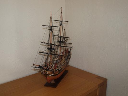
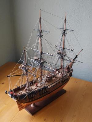
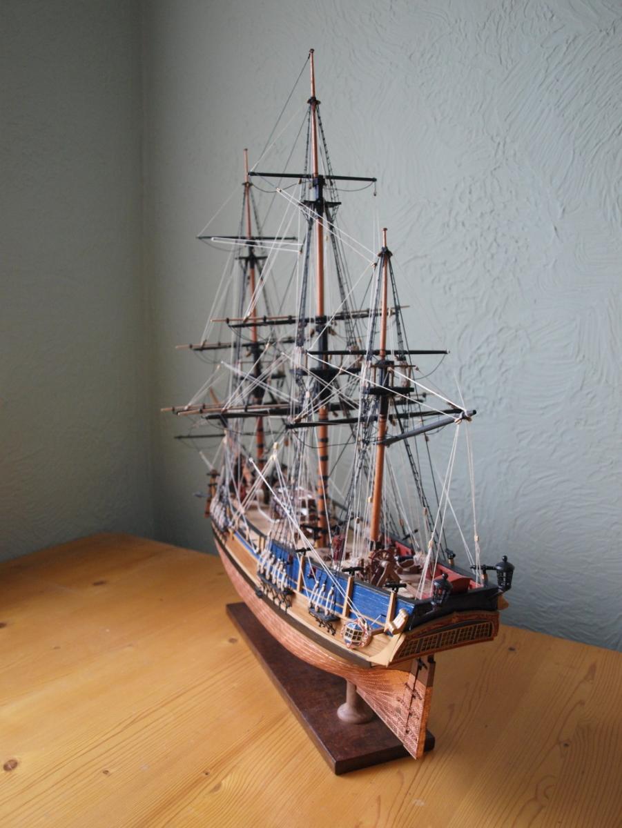
As I said in my last post I will now present a few photographs showing more details with the final shot showing the model in its final resting place in the lounge.
Danny


-
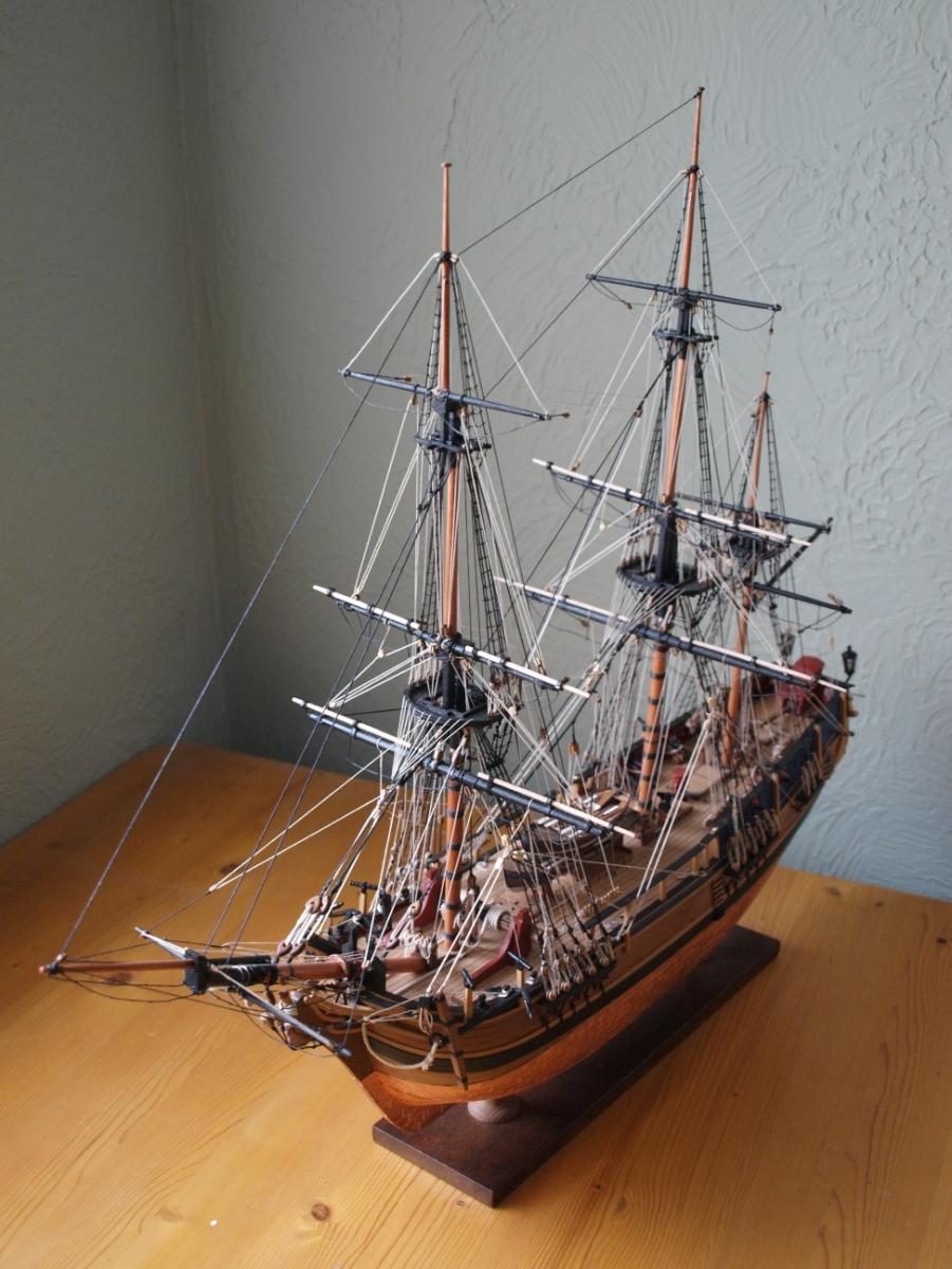
Hi
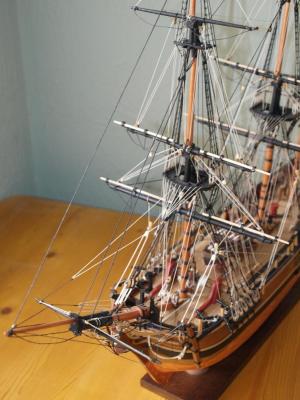
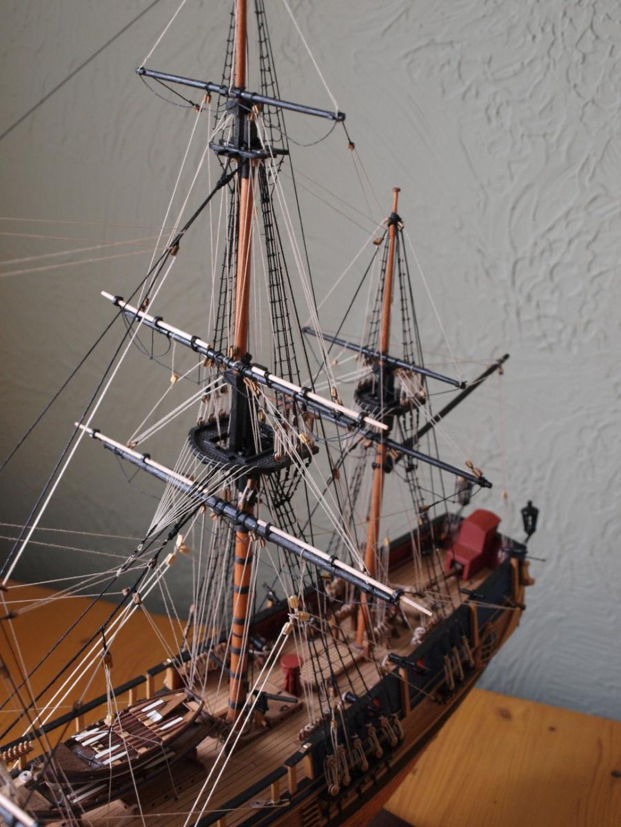
I haven't posted for a while as I have been completing the running rigging and decided it was not worth posting dozens of photographs showing each bit as I did it. Anyway I have finished it now and the three photographs show the final result. I have some more detailed shots to process and will put them in the next post.
Danny


-
At last managed to get a bit of reasonable light so am including a few pictures of the running rigging done so far. The first two show the running rigging from threar and the second two from the front. The second two also show the crows feet on the main and mizzen stays. I have actually done the foremast as well but haven't included a photo of this.
May I take this opportunity to wish anybody reading this, the seasons greetings and my best wishes for the new year
Danny


- Captain Slog, edmay, natnat and 1 other
-
 4
4
-
Thanks Pavel. You are right, now starts the fiddly bit. I have actually completed the mizzen running rigging and crows feet and am intending to publish a photograph but am having to wait for some decent light. The weather here has been very cloudy and we have had a lot of rain. Although I have a flash on my camera it tends to cast all sorts of unwanted shadows. The forecast is good for Boxing day though so am keeping my fingers crossed..
May I also offer you the seasons greetings and for a happy and prosperous new year.
Danny
-
Sorry about photographs 3 & 4 in my last post. As you can see I have now put them the right way up.
Danny


- natnat and petervisser
-
2
-
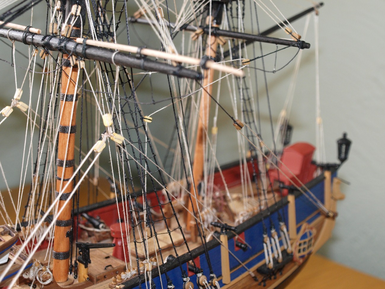
Hi
More progress : I have completed the standing rigging as can be seen in photograph 1. As you can see I have also done all the rat lines. I did this as I went along with the standing rigging so as to make the job a little less boring. The other photographs show the rigging in more detail.
As a matter of interest, the manual gives very little detail in the rigging process but fortunately I still had the manual for Granado which is excellent in this respect and although slightly different in some respects proved to be very useful. For example it gives very detailed instructions on setting up the crowsfeet which I have now completed but not yet photographed but will be seen in the next batch of photographs which will show the initial mounting of the yards.


-
Hi
As can be seen in photograph 1 the lower shrouds have now been completed with a close-up view of the lower foremast shrouds in photograph 2.
I am will also starting the ratlines on the lower shrouds as I install the topmast shrouds so as to spread the load so it does not become too monotonous I have already started on these but found the black cord I was using did not hang to well and its twist tended to make them difficult to tie and they did not quite look right. As a result I switched to the 0.1mm white cord provided in the kit and resigned myself to painting them with indian ink. this in fact turned out to be fairly straight forward and they looked much more realistic.
Will now get started on the topmast shrouds wich will of course be a bit more difficult as the deadeyes are that much smaller.
Danny

- petervisser, canoe21, AJohnson and 1 other
-
4
-
Hi Peter
Thanks for your kind words. I've started on the fore mast shrouds and am about half done. I'll post a photo when I HAVE FINISHED.
Danny
-
Hi
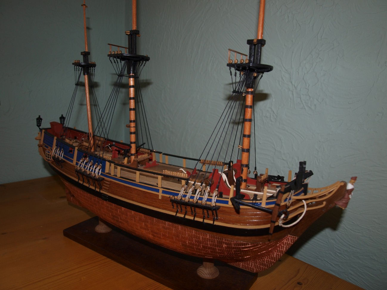
Have now finished the hull and fittings as can be seen in photos 1 - 4 and have also completed the bowsprit, masts and spars : photos 5 - 6.
The masts have now been installed and am about to start on the lower shrouds. I think this may take a while as there are so many whippings and knots to be tied and sealed and I have to keep waiting for the sealant (white glue) to dry. Anyway I'll keep you posted.
Danny
- The Sailor, natnat, petervisser and 1 other
-
4
-
Hi
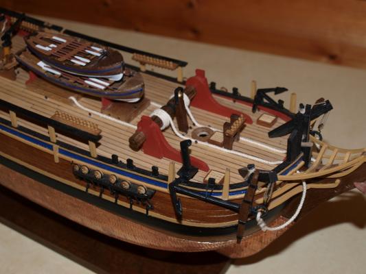
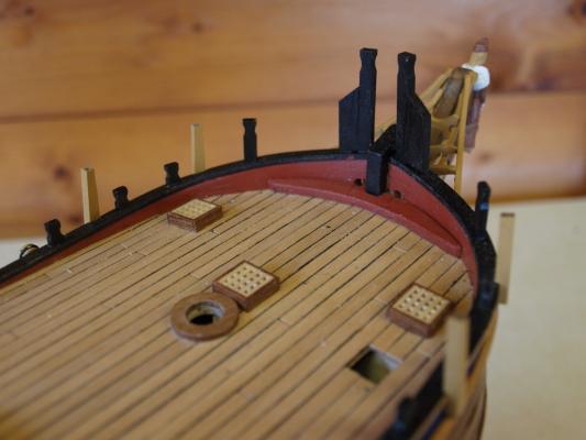
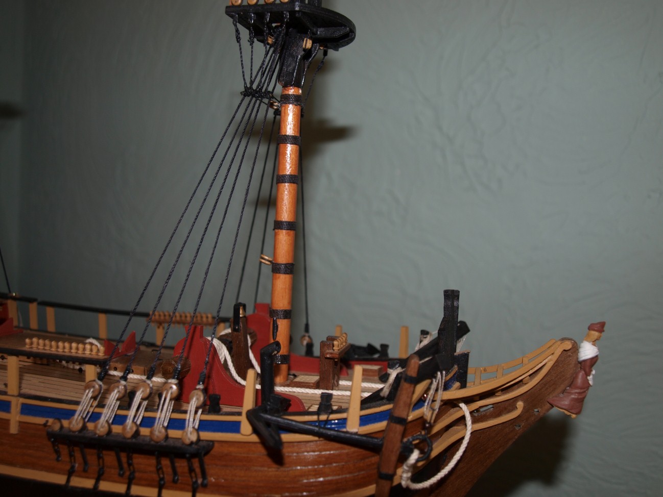
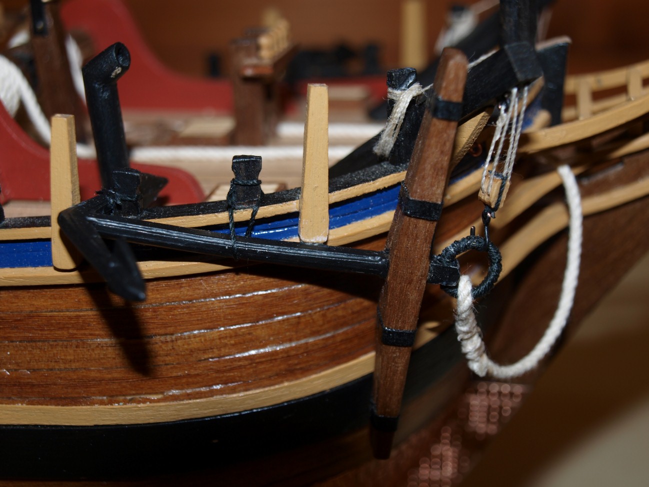
As can be seen in photograph 1 the anchors and anchor cables have been completed and installed.
You may also notice that I have also installed some cat falls which were not on the plans but have been made to the same design as those on my model of the bomb vessel Granado.
Photograph 2 shows how the anchor cable has been arranged. Again this has been copied from Granado. The plans suggested coiling the cables flat just aft of the windlass but I thought that since Bounty's anchor cables were 600 ft long this seemed a bit unrealistic. I couldn't find any information on how the cables were fed to the cable tier but know this was somewhere in the hold. I have noticed several versions show the openings in the corner of the main hatch so have stuck to this.
I have now started on the masts and spars but will leave progress until next time.
Danny

-
Thanks for your comments folks.
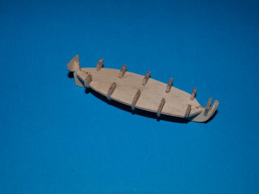
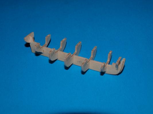
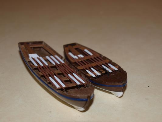
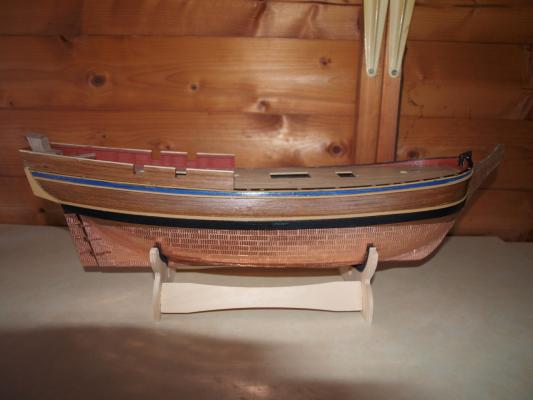
Pavel : The photographs of the two finished boats are the new ones to go on the current model. Those with the blue background are from my previous model photographs of which can be seen in the gallery.
Danny
-
With reference to David B's comment on adding softener to the water when diluting white glue, I add a drop of washing up liquid to my brush cleaning water and used this when diluting prior to applying to some 0,5 mm foot rope for my Bounty. I applied the diluted mixture to a length of line, wiped it down with a kitchen towel and allowed it to dry under tension. The line was then fairly stiff (obviously the PVA had penetrated OK) and was perfect for the foot ropes, taking up the correct curve by teasing with my fingers. The result was far better than using the untreated line which tended to go where it wanted.
Incidentally I have made several models since the 90's and used CA for sealing knots on most of them and have not had any rigging breakages on any of them.
Danny
-
Thanks ZyXuz, They were quite tricky to build as they are quite small and the 3x0.5 walnut strips were inclined to split. Anyway I think they are acceptable at a distance.
Danny
-
Hi
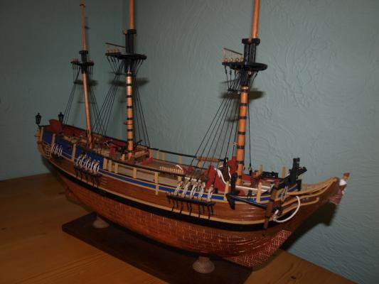
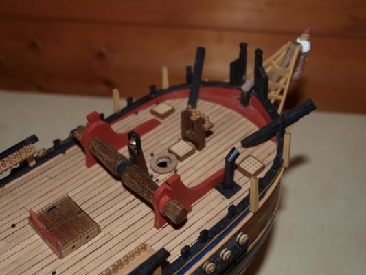
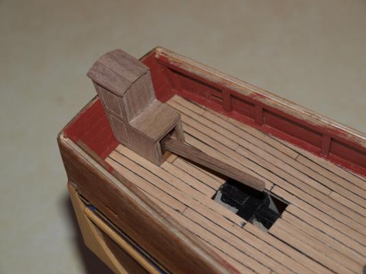
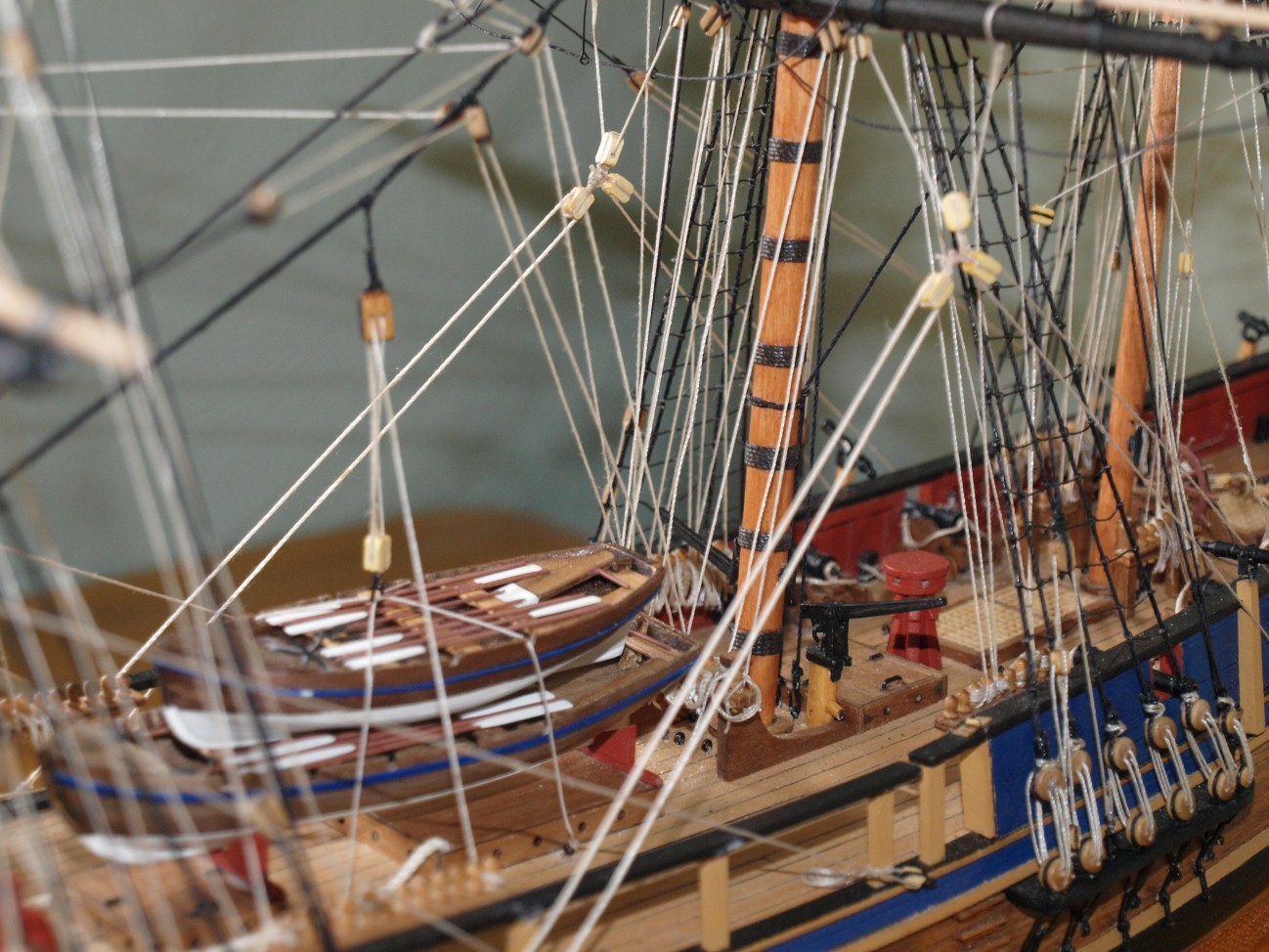
As can be seen in photograph 1 the fore deck fittings have now been completed. The windlass, cat heads and fore bits are more or less the same as in the instructions but the galley chimney has been scratch built to the dimensions given in McKays anatomy book.
The two ships boats have also been constructed. Photos 2 and 3 show the initial stages of construction (these were taken of the boats made for my 1st Bounty model) and photo 4 shows the final results. The colour scheme chosen is also based on the front cover of McKays book.
The next job will be the anchors and anchor cable.
Danny
- natnat, The Sailor and AJohnson
-
3
-
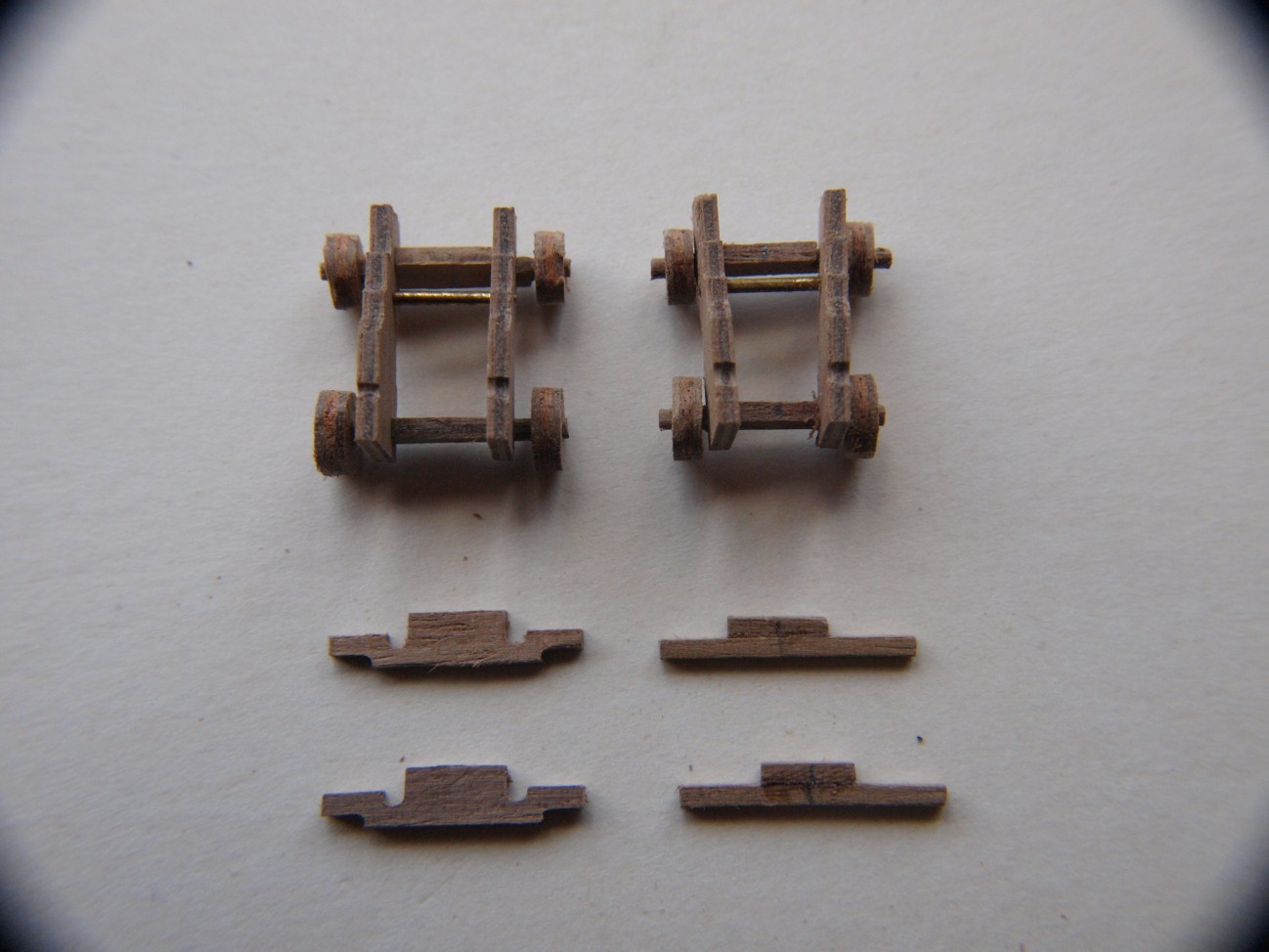
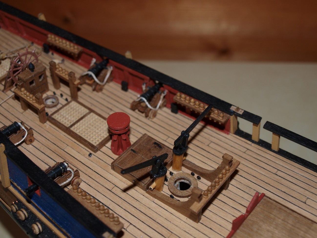
Hi
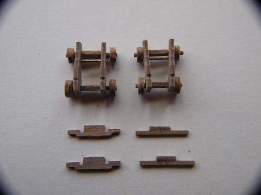
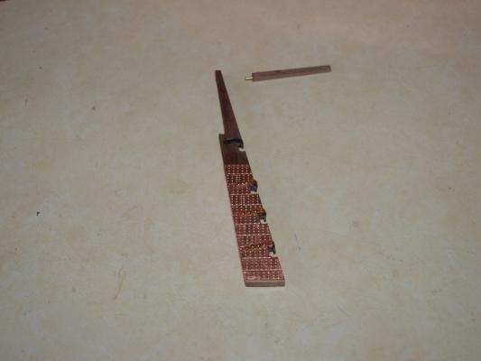
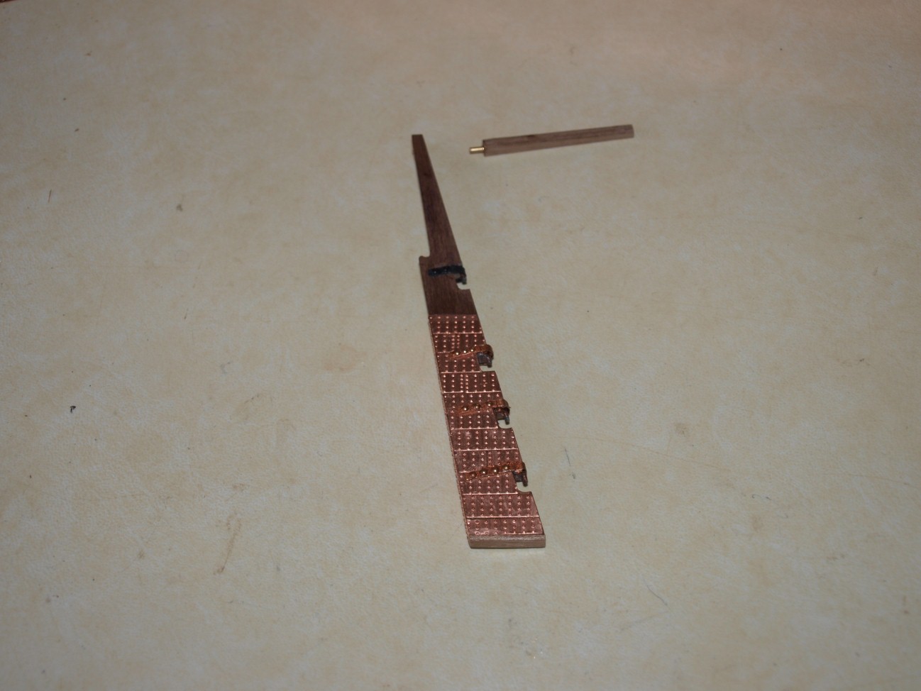
Next item to be tackled were the canons. The carriages as supplied looked wrong as they had parallel sides which should be narrower at the front than at the rear. I got around this by making some new spacers using 1 mm square walnut strips as shown in photograph 1 which shows the originals on the left with the resulting carriage above and the modified spacers again with the result above. The installed guns are shown in photograph 2 which also shows the capstan and elm tree pumps.

- AJohnson and The Sailor
-
2
-
Thanks for your kind comments Mathew. I personally think the Caldercraft kits are the best and I have made others.
I have actually made a lot more progress on my Bounty and will be updating my log soon. In fact I have almost finished all the hull and fittings and have started on the masts.
Danny
-
Fittings continued...
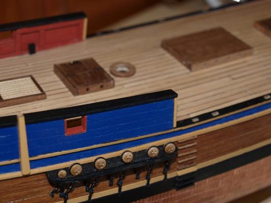
The final hull fittings (apart from the Mid Deck capping which was to be fitted later due to its vunerability while working on other deck fittings) were the channels with dead-eyes and chains. Examples of these can be seen in the first two attachments.
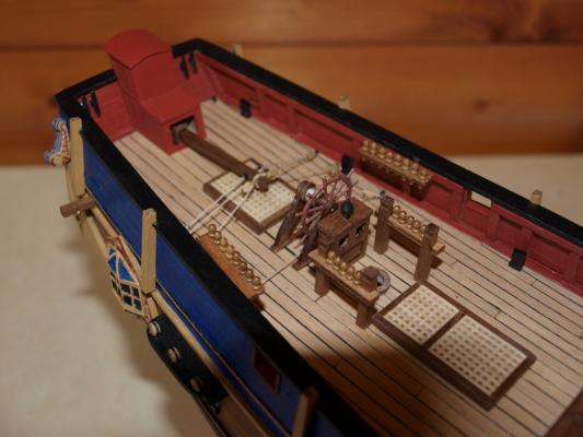
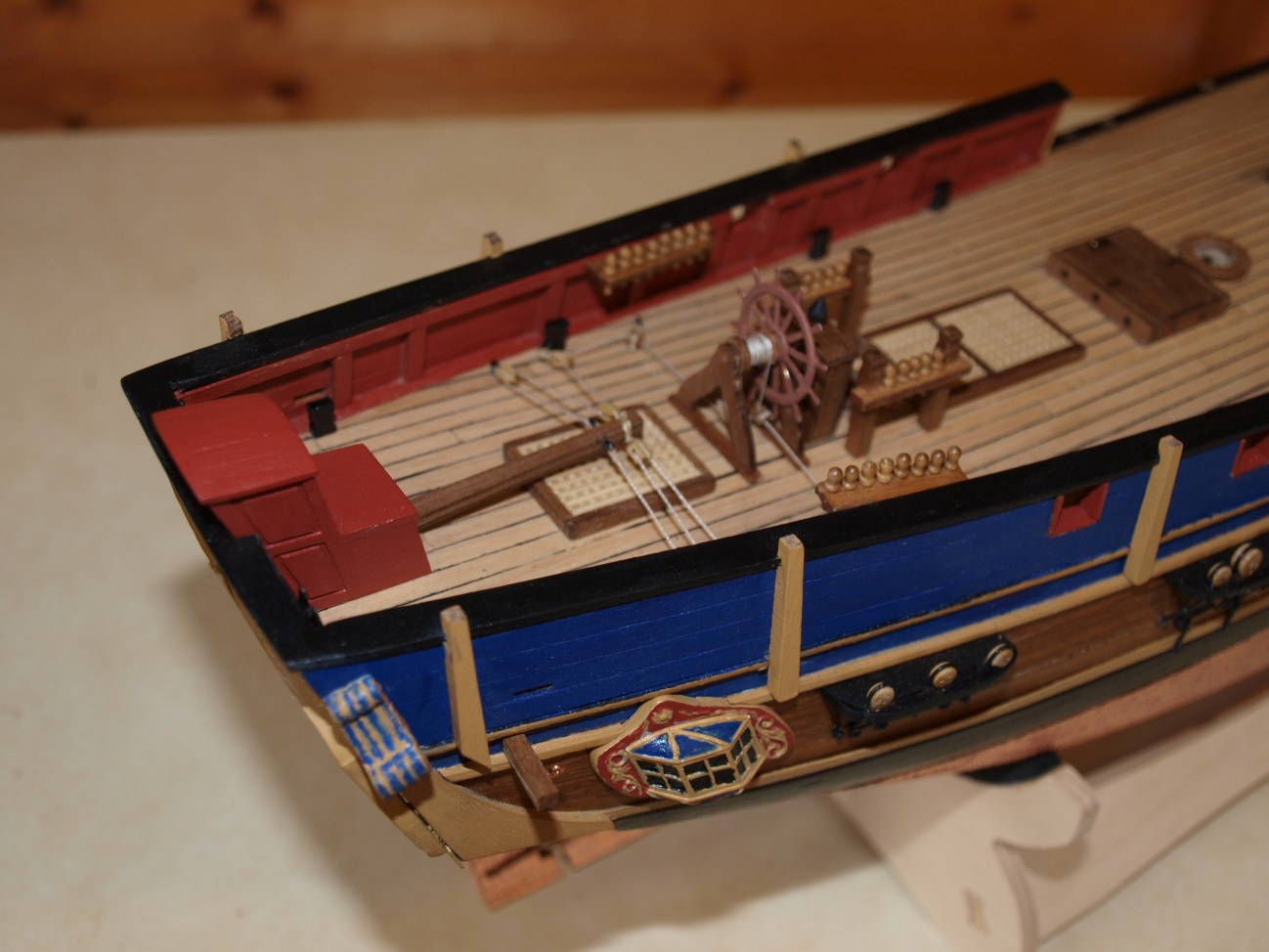
After this the deck fittings a start was made on the deck fittings working from stern to bow.
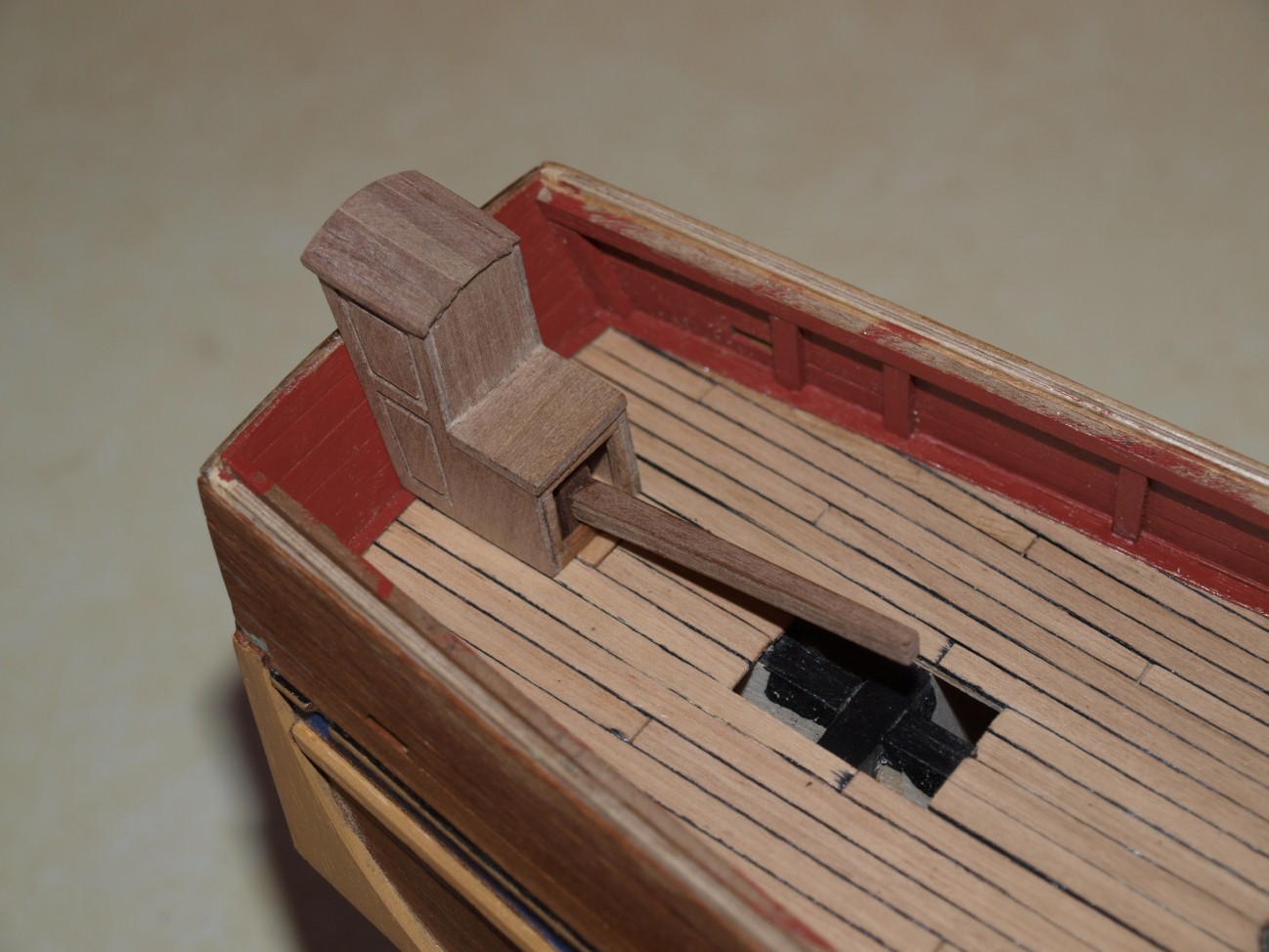
The first item was the wheel and steering gear as shown in attachments 3 and 4. This also meant fixing the tiller bar and flag locker. The binnacle was also fitted at this stage and a small chimney added which was not in the kit. I think it is probably a bit larger than it should be but was quite small and difficult to manufacture as it is.
Next to be fitted will be the mizzen bits and the capstan.
Danny


-
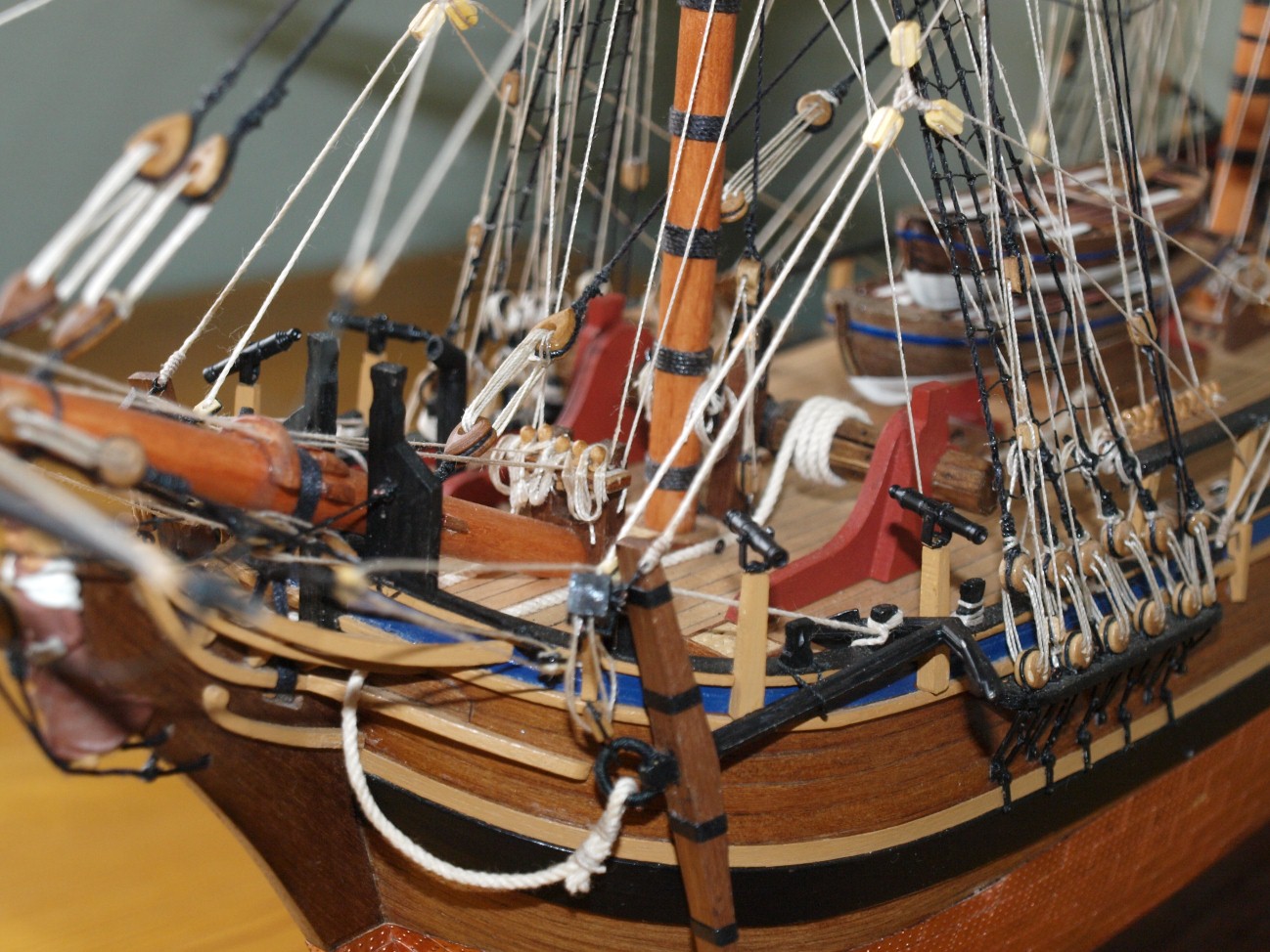
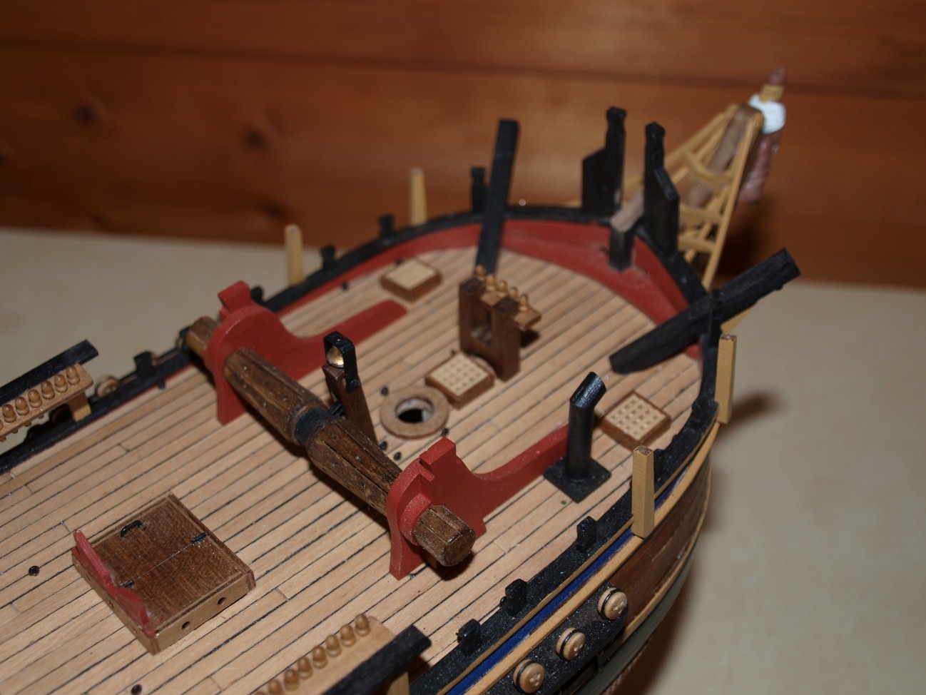
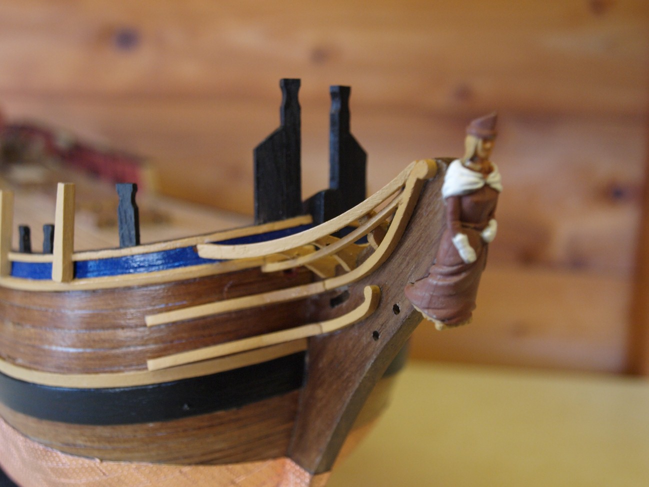
Quite a bit done since my last post so will describe them in stages which explains why some bits not mentioned may be noticed.
The construction has generally procedure as per manual with the hull fittings the first of which were the timber heads which can be seen in both the first and second photographs along with the swivel gun supports which are shown in all 3 photographs.
The next item were the head rails and figurehead which are shown in photograph 2. I'm afraid the figurehead is slightly out of focus due to the narrow field of view of the camera.
Photograph 2 also shows the forward scuttles which were in fact added later.
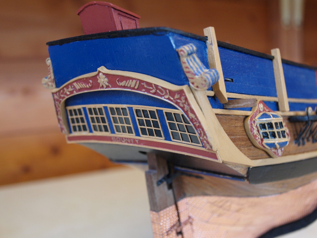
Photograph 3 shows the stern windows and decorations with a side view of the quarter gallery. I did in fact modify the latter as the casting supplied had flat tops and bottoms to the windows so I carved some tops (painted Blue) as described in Mckays AOS book.
Will continue in next post.
Danny


-
Hi Richard
Thanks for the comment. I am reasonably happy with the result but I found I had to do an awful lot of shaping with the method used.
I think I might replace a few of the plates now I have finished and have a few spares,
Danny
-
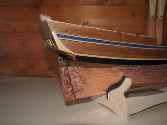
Coppering now finished as can be seen from the attached photographs.
The tiller has now been attached to the rudder using a slightly different method than in the manual. This has been done to enable a frame to be added to the opening in the flag locker as per Mackay's drawings and allow more convenient tiller adjustments (eventually !).
The rudder straps have been painted bronze and top straps added (assumed to be standard as there is no contact with copper to cause galvanic action) as they was not supplied in the kit.
Next - bow rails - a tricky job!
Danny

- AJohnson, Captain Slog, canoe21 and 2 others
-
5
-
Hi
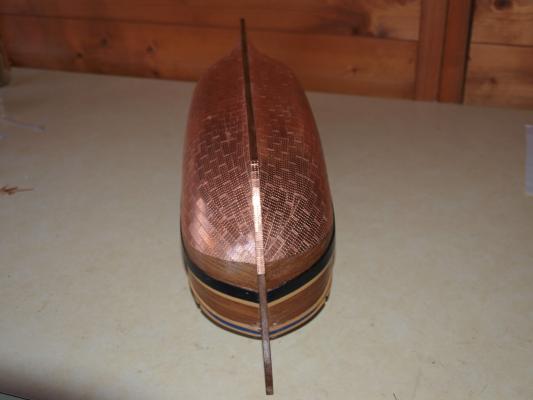
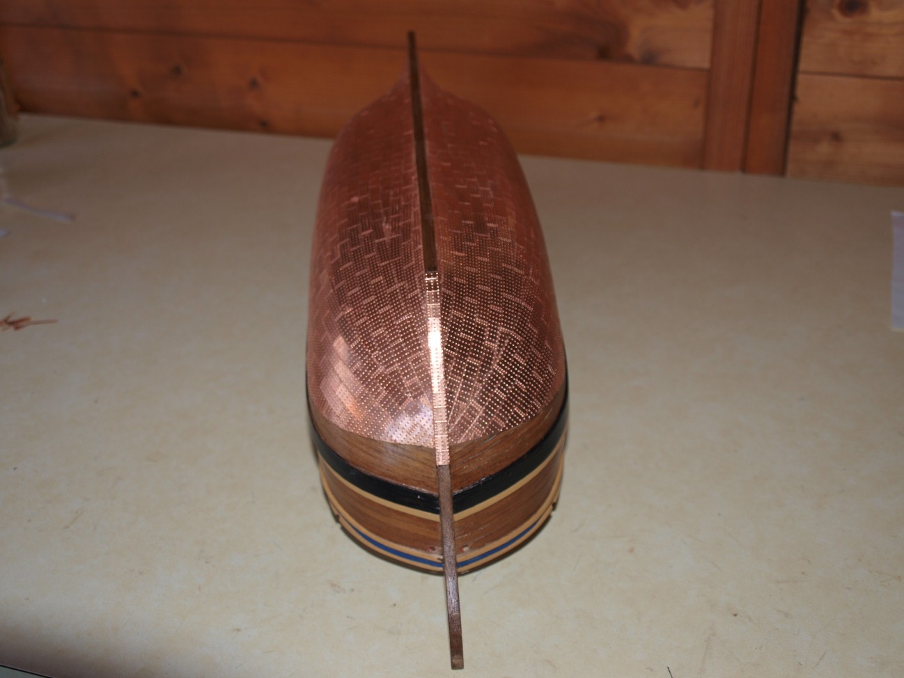
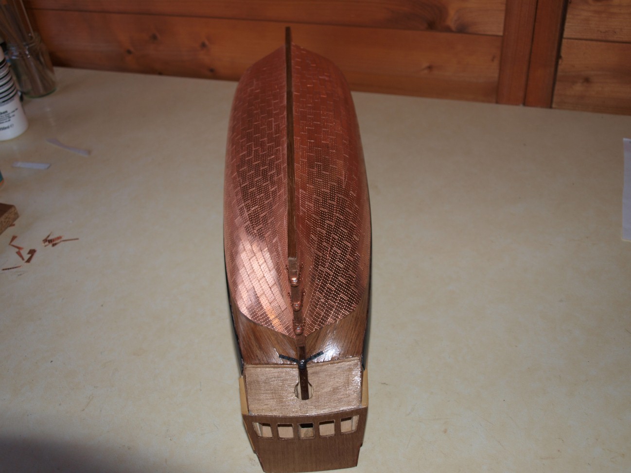
Copper plating started as can be seen from the attached photographs.
Photo Bounty24 shows the technique used which is based on the method used by Keith Julier in his articles on constructing the Victory in Model Boats magazine.
Starting at the centre where the waterline is straight, the plates were fixed in layers of two and one until a batten laid across the most recent plate(s) cuts the waterline at its extremes. The line of this batten was marked and plates laid along it as shown.
The remaining plates are then fixed from the keel upward shaping them as required.
The result produces a similar result to that shown in Mackay's Anatomy book.
The photo actually shows the starboard side the port side already having been completed as shown in the other two photographs.
Danny


-
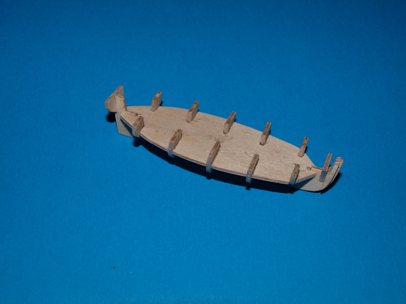
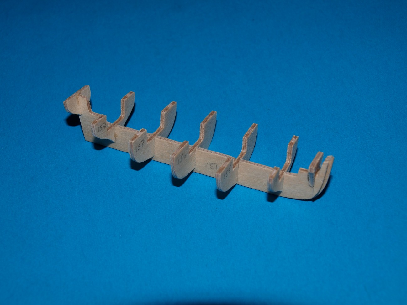
More progress :
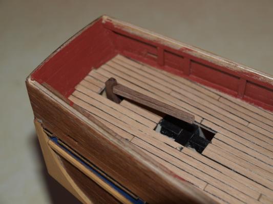
I have at long last finished planking the deck as can be seen in the attached photographs.
It is the first time I have tried marking the edges with a black marker pen and the results do not seem too bad although a little uneven.
I have also added the inner support timbers to the aft bulkheads which I wanted to add after the deck was finished.
A further addition was the breast hook. This item was not included with the kit but is a fairly promminent feature so thought I would add it. I made it from some scrap to the dimensions shown in Mackays's book. I also bored the hawse holes at the same time as their position was more critical when the breast hook was in place.
I also made up the flag locker (not shown in the photographs) so as to help when finishing off the stern area.
Finally as suggested in the manual I fitted the rudder before beginning the next major job of laying the copper plates. This, in fact proved to bee quite a long process as the parts were a bit too large and had to be filed down to enable the rudder to be removed and replaced later.
Danny


HMAV Bounty by DanPage - FINISHED - Caldercraft - Scale 1:64
in - Kit build logs for subjects built from 1751 - 1800
Posted
Hi Bindy
Thanks for your comments on my build. I think that although the final result, as you say, looks ok I'm afraid it pales into insignificance when compared with some of the builds I have been following. Some of the scratch building is truely awesome and the research that goes into with it incredible.
I have had a look at your logand you seem to be progressing very well. As you say MSW is a great place for getting advice.
Danny