Deacon
-
Posts
57 -
Joined
-
Last visited
Content Type
Profiles
Forums
Gallery
Events
Everything posted by Deacon
-
 Thanks Greg. It's a little of both. The starboard side is a bit narrower but it is also accentuated by the camera angle. As you can see, the original printing on the plywood was less than accurate. The frames are 3/16" T. plywood, so the grain you're seeing is only the outside layer. And yes, they are delicate. Plywood is approx. 45 years old, but is generally in good condition. The deck beams will be Maple, primarily because it is readily available here, economical, and should prove to be much stronger than the kit's original plywood beams, adding strength and rigidity to the frames. Working with a vintage kit like this presents a lot of challenges and makes one appreciate the materials and technology of modern day kits.
 -
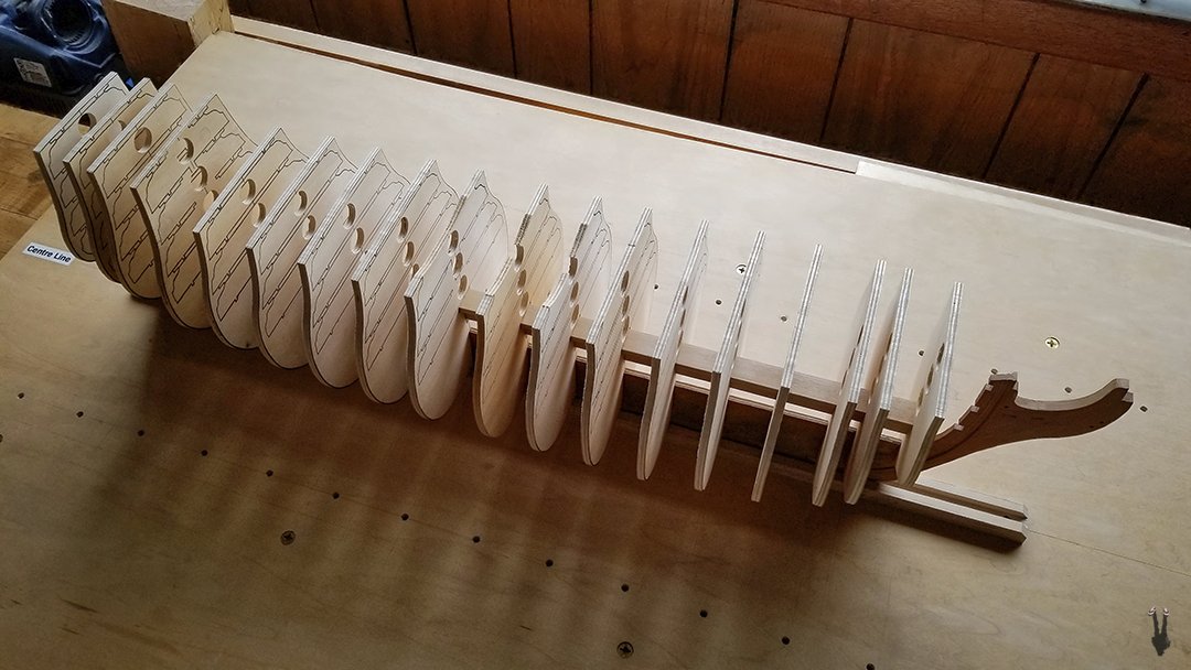
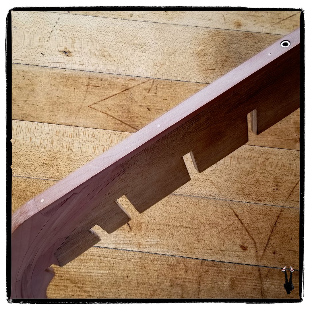
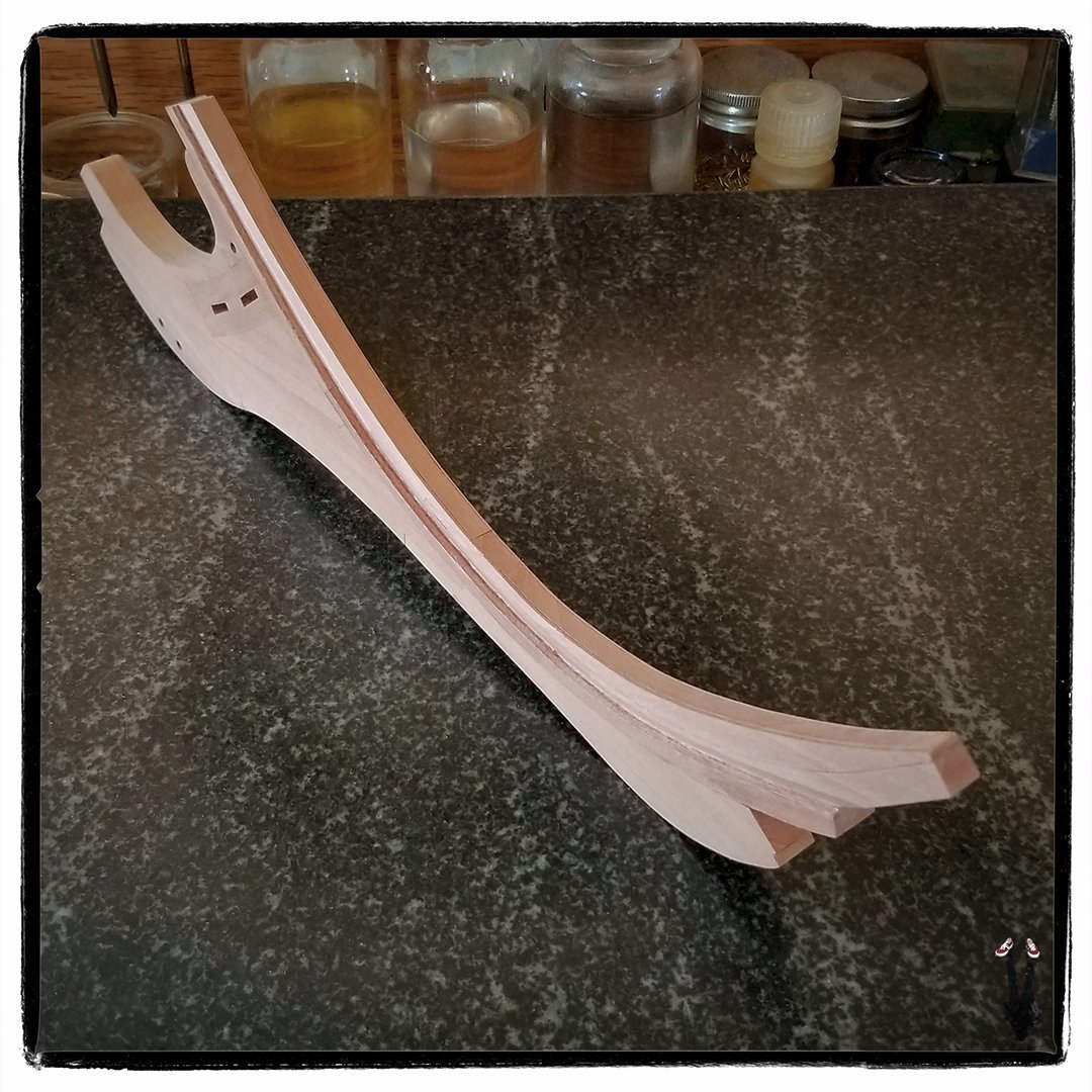
Finally a bit of an update. Bulk of scroll saw work completed on the frames. What's left to cut are the half-lap joints on the hanging knees for the deck beams. Decided to cut and mill all the deck beams from solid timber. Presently building a pivoting table for the scroll saw which will allow me to cut the beams to a consistent radius and depth. Radius of the beams does increase slightly as you move up through the decks, but at 1:98 scale, the change is so small it would be unnoticeable, so all beams will be cut to the same radius. Once the curved beams are cut, I'll mill the grooves for deck stringers and the half-lap joints on the beams, then cut the half-lap joints on the frames to fit the beams. After that, the frames can be permanently installed to the keel and stringer, then beam and decking installation can begin from the lowest deck and progress up through the five decks... a ways to go before that can happen.
-
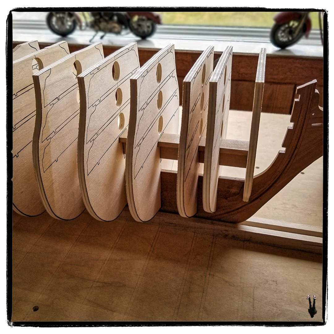
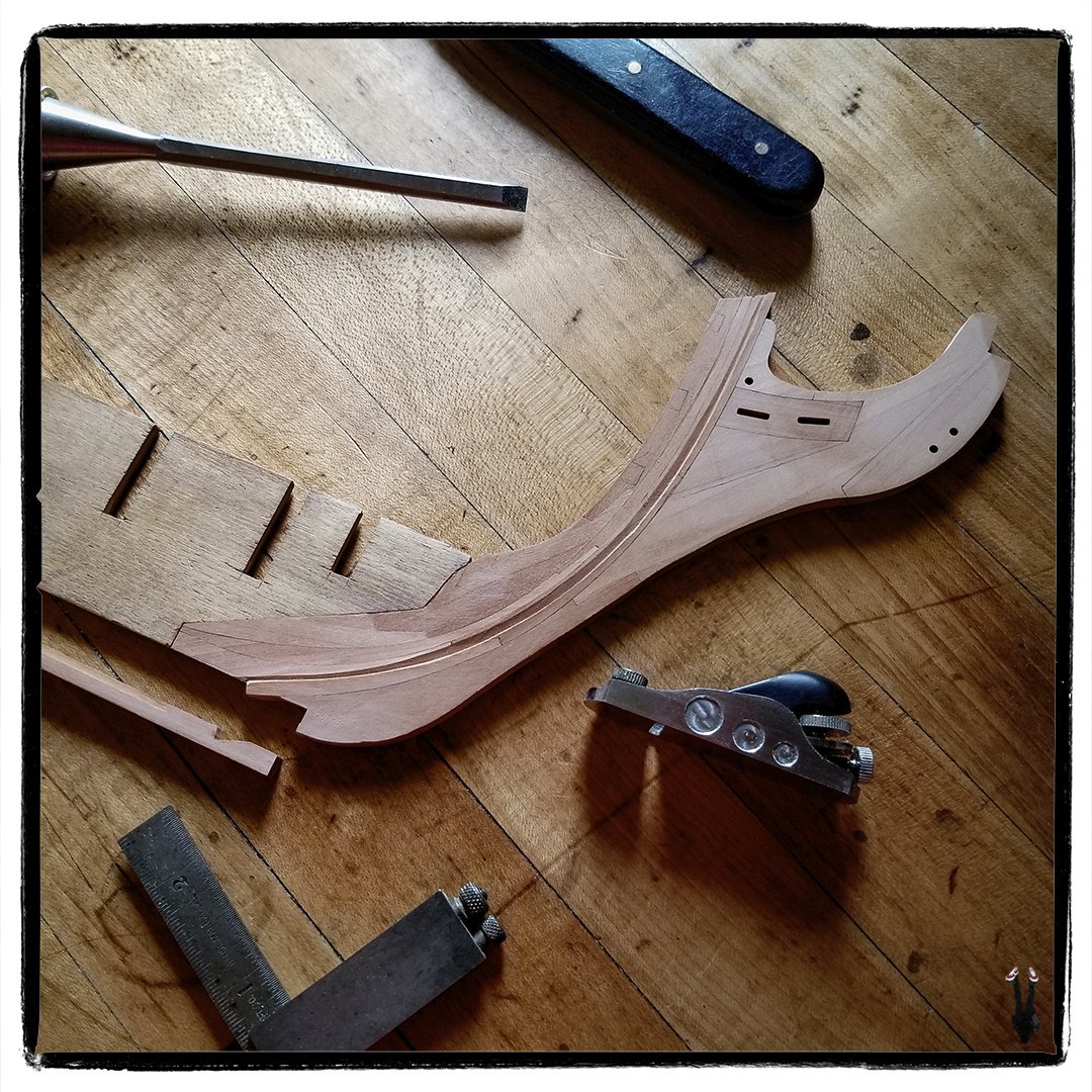
After milling and paring out the T-slots in all the frames, I did a test assembly of the frames, T-stringer, and keel. Be a bit of a tricky process when it comes to glue-up, but as it is, it's a strong, rigid assembly without the glue. Next step is to finish flattening a couple of warped frames, then cut out the waste areas between the deck beams on all of the frames.
-
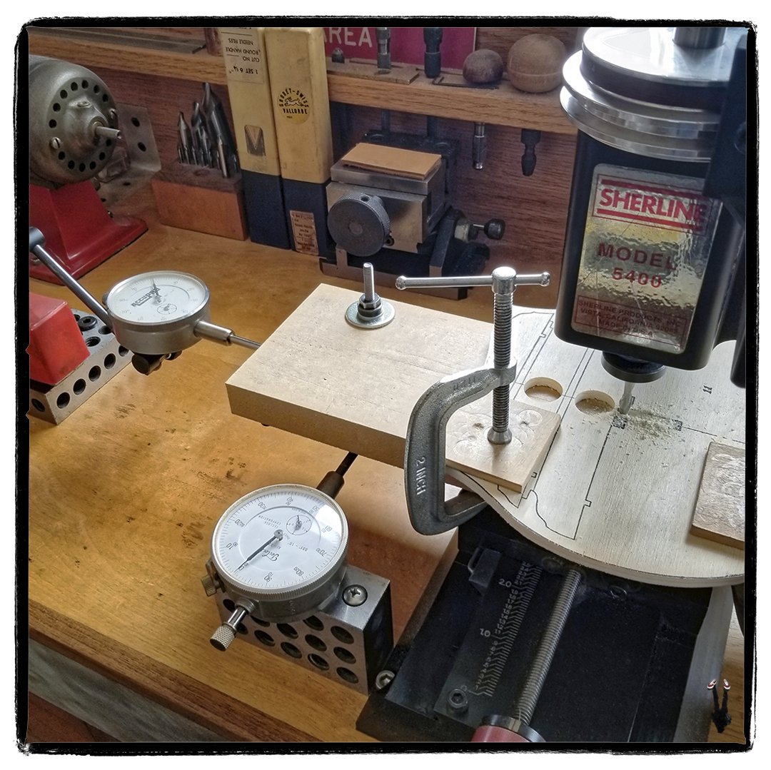
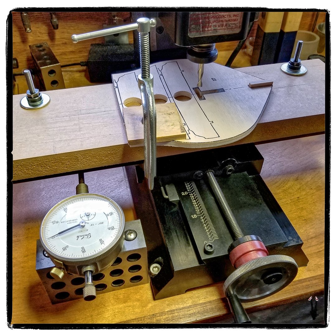
Crusing along milling the T-slots in the Victory frames. I added a second dial indicator providing dial readout on both axes, increasing efficiency and accuracy. In photo, vertical slot has been milled, cutter is at the zero point ready to mill the horizontal slot.
-
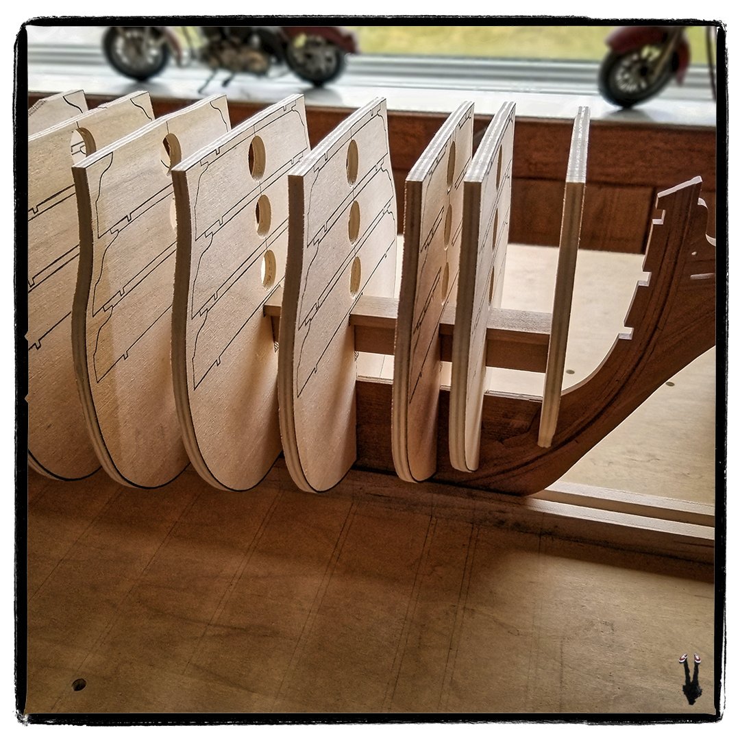
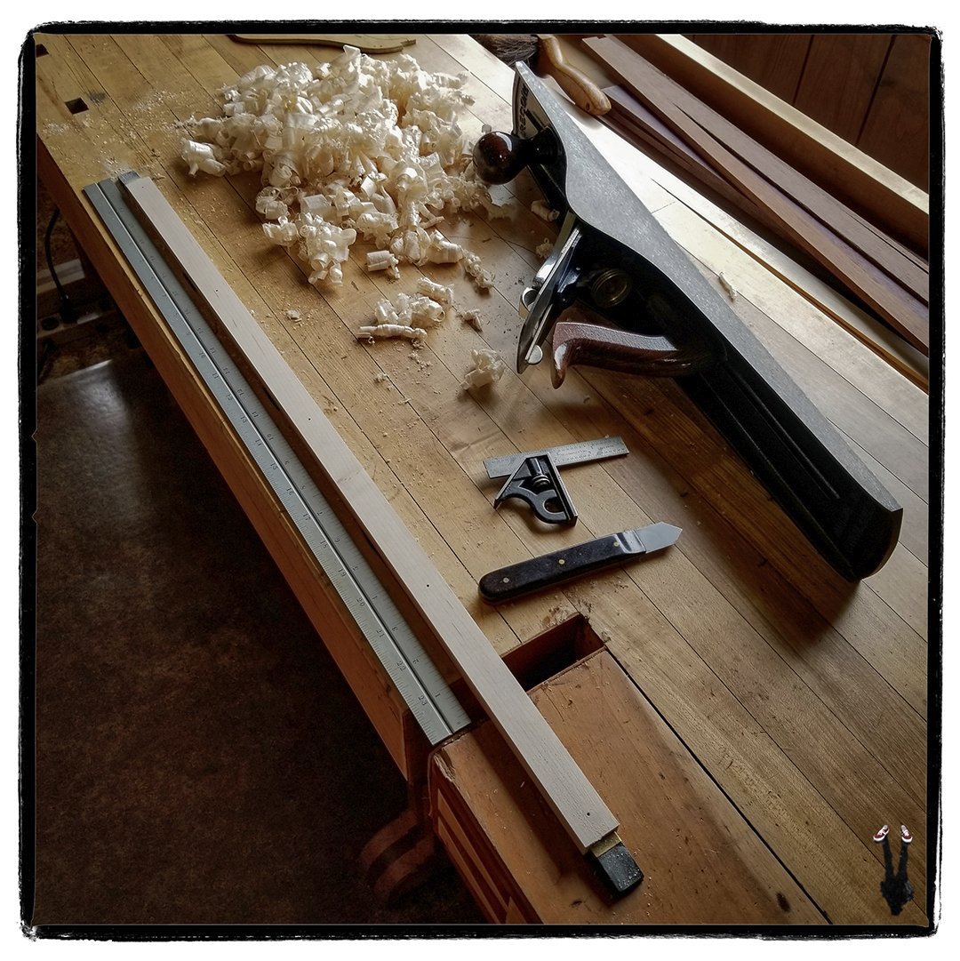
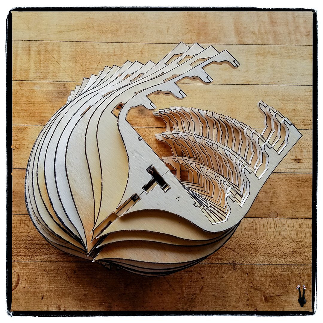
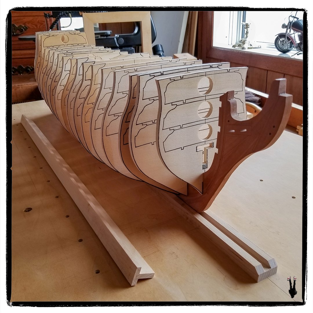
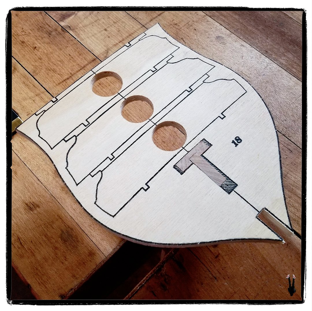
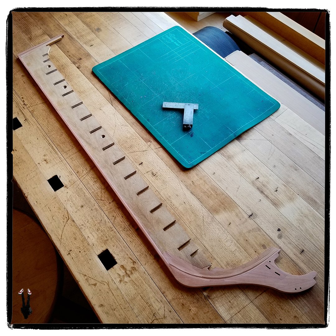
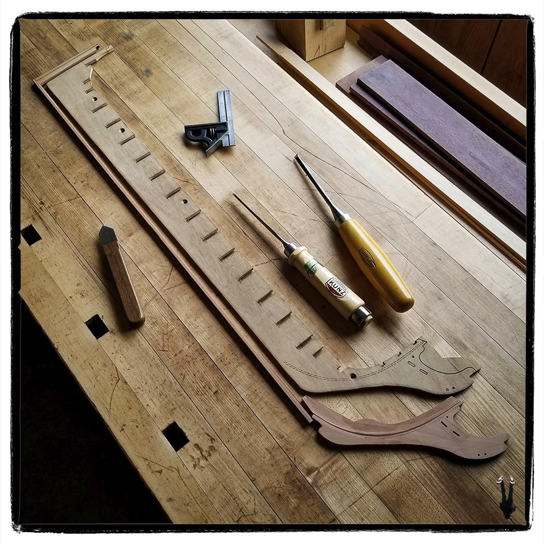
Finally have an update on the Victory project. The past several months have been something of a challenge. A long-standing CG watch animation project, put on hold during the pandemic, came back to life after the watchmaker was granted a patent on his new escapement design, so I am spending most of my time in the animation studio working on that. In addition I recently completed a program of radiation treatments (succesfully as far as we know at this time) which took a great deal of time and energy. Now that treatments are finished, I've been able to make some time for the workbench while work progresses on the watch animation, which will continue to take most of my time for the next few months. It certainly feels good to be back at the workbench, I've missed it. I've cut out all of the frames on the scroll saw and milled/pared the slots in the frames where they attach to the keel. Photo shows them lined up temporarily on the keel on the build board. The holes in the frames were bored with a Forstner bit as access holes for cutting out the waste material in the deck regions. The large hole makes it easier to set up cutting angles in the scroll saw. In the foreground is the "T" reinforcement stringer that runs the length of the hull from the furthest forward frame to the aft-most frame. Currently I'm milling openings in the lower portion of the frames to accept the "T" stringer. The photo shows the milling setup. I made an MDF sacrificial table onto which I scribed a centre line with the mill, then milled a small slot along that centre line to accept a piece of scrap keel stock as a locator. The frame is slid into place on the keel locator, then centre line alignment confirmed before clamping the frame to the table and milling the "T" slots. In this way the "T" slots are aligned accurately with the keel slots. After milling, I square up the ends of the slots with a small chisel. I'm referencing off the frame centre line for all milling operations, as the printed cut-out lines are less than accurate on most of the frames. That is particularly obvious in this photo which shows the forward frame in position on the "T" stringer. The printed cut lines are considerably off centre. I also reduced slightly the overall size of the stringer by truing up the stock supplied in the kit and assembling the stringer with a machined rabbet in the top piece for added accuracy and strength. That's it for now. Once all the "T" slots are milled, it will be time to cut out the waste material in the deck areas with the scroll saw and hand-held jewellers saw. I'm considering replacing the plywood deck beams with machined solid timber pieces for greater accuracy. Not sure yet, will depend on how the cutting goes.
-
Thank you Bill. Which Aeropiccola kit are you building? All the solid wood in the Mantua kit is usable. The plywood though is a little sketchy in some areas, so my plan is to replace all the visible plywood with solid timber which adds a great deal more work but should result in a better finished product.
-
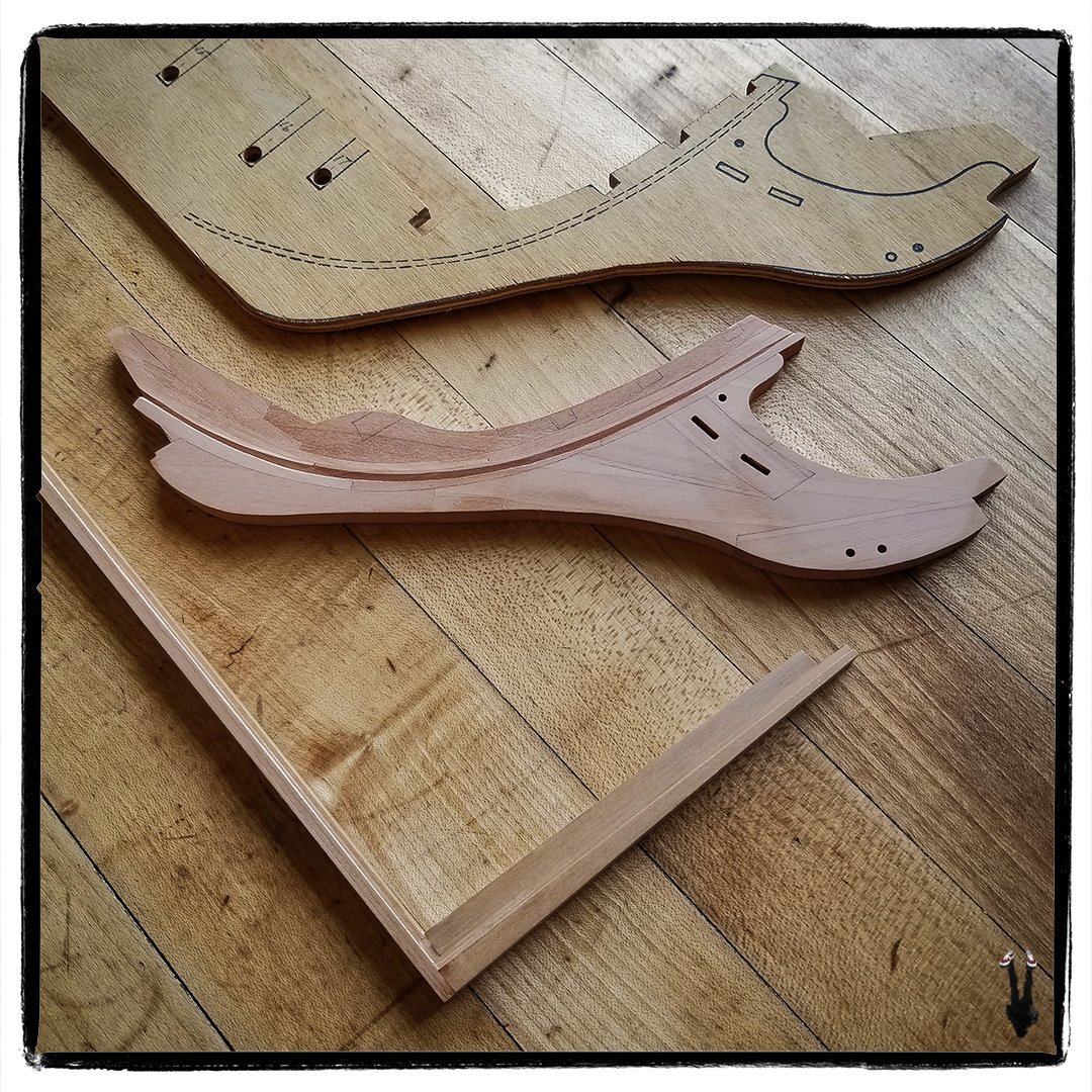
After months of intermittent work on the keel, attention can now be turned to the Victory frames. First photo shows the full keel assembly with the solid timber keel, sternpost and bow timbers married to the modified Mantua plywood keel. Second photo is a detail shot of the forward section showing the Boxwood treenails used to reinforce the solid timber keel to plywood joint. There are also three brass "treenails" (not visible) reinforcing the joint between the bow timbers and the plywood. These pins come in from the top of the plywood keel and pass into the bow timbers. Near the upper right of the photo you can see one of the two threaded brass inserts in the keel which provide the option of mounting the hull to machined support pillars as opposed to a cradle.
-
It's been a long time since I've posted an update on this project. Took July off from the model bench to build a vendor display (in Maple and Purpleheart) for my sister's embroidery business. Because of its size, that project took over the entire workshop. Our two remaining Ash trees were felled last month, so I've been spending a lot of time flailing about with a chainsaw, schlepping logs, and splitting firewood... it never ends. Concerning the Victory, the solid wood Bow Timbers are now glued up to the modified Mantua plywood keel and the joint has been cut in the solid wood Keel/Sternpost assembly, ready to be glued and treenailed in place.
-
Welcome aboard Abbot. This a great and helpful community regardless of what medium you model in. I expect your first hand knowledge of the U.S. Navy and your research into its history will prove of value to modelers in that discipline.
-
Beautiful workmanship... well done indeed!
- 840 replies
-
- 3
-

-
- winchelsea
- Syren Ship Model Company
- (and 1 more)
-
Welcome to MSW DeHammer. Looking forward to watching your progress on the Bluenose, our iconic Canadian ship!
-
Just finished milling the frame slots in the original Mantua plywood keel. Bottoms of the slots were squared up with chisels. The screw holes in the plywood keel were used to mount it to the sacrificial MDF table in the milling machine. Photo shows all the major components for the keel. Now it's time to cut down the plywood keel to accommodate and join the scratchbuilt solid-timber keel, sternpost, and bow timber assembly.
-
Welcome to the forum Scott, from Ontario...
-
Very sorry to read of the loss of your son Keith. We're not supposed to outlive our children, it's against the laws of nature. The death of any loved one leaves us adrift. It's through the support of family and our extended family that we can get back on course and continue as our loved one would wish us to.
-
Small update on the Victory build. The scratchbuilt solid timber keel pieces are now complete. Time now to finish milling the original Mantua plywood keel structure, remove the sections being replaced with solid timber pieces, then assemble the new keel structure. You may notice I added additional pieces (stemson and apron) to the bow portion in order to replace the entire plywood bow section, and make a stronger assembly. The original plywood keel is warped in that area and thus unusable.
-
Beautiful work Glenn. Really enjoying watching your progress.
- 840 replies
-
- 3
-
-
- winchelsea
- Syren Ship Model Company
- (and 1 more)
-
Reading through your build... excellent job.
- 840 replies
-
- 3
-
-
- winchelsea
- Syren Ship Model Company
- (and 1 more)
-
Minor update on the Victory. I planed a taper on the underside of the Buildboard's keel strip with a Jointer plane, removing .122" (one scale foot) at the aft end of the strip and nothing at the bow end. The Victory was built to draw one foot more aft than forward. By tapering the keel strip it will make it easier to keep waterlines level during construction. Trueness of the taper was checked with a precision straight edge and square.

-
Thank you Rob. The plan with the Mantua kit is to replace any visible plywood elements with solid timber. I haven't checked every piece by any means, but the wood stock in the kit still appears to be in surprisingly good condition. The plywood pieces though have suffered over time from chipping and warping. Since no ply will be visible I'm not overly concerned about the edge chipping, but the warping is an issue which will have to be addressed on a per piece basis.
-
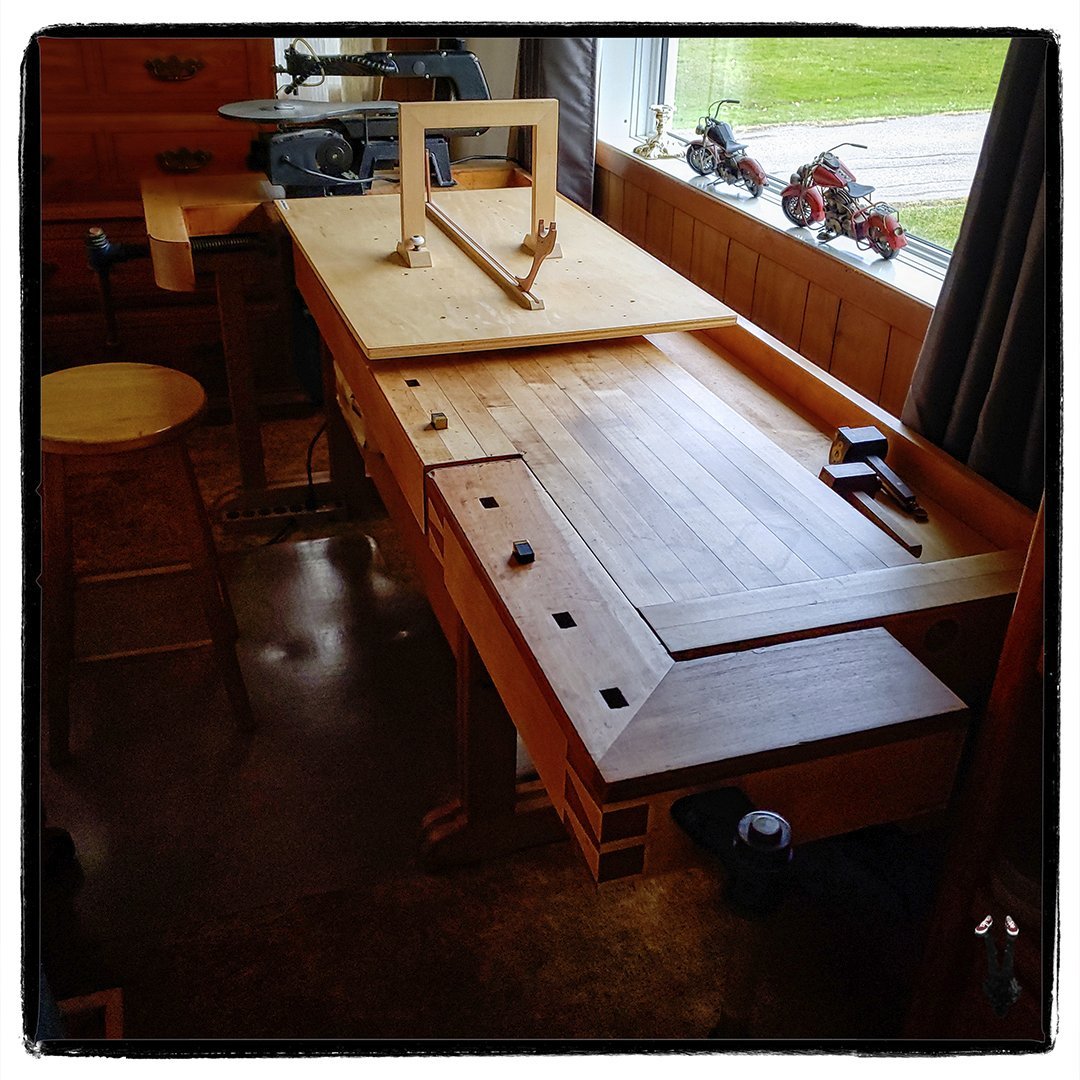
While not a construction post for the Victory, this post is relevant to continuing work on the model. Spent the past couple of weeks rearranging the workshop to accommodate my cabinet-makers bench. The bench has lived in the garage for the past seven years which has limited its usability to six months of the year due to the garage not being climate controlled. Now that it's in the modelshop in the house, it's in a stable environment and is available for year-round use, primarily to function as the dedicated "shipyard" for the construction of the Victory, though it will be pressed into service for some other woodworking projects on my to-do list. In the photo the Victory buildboard is in place with the keel set into the keel support. I built the bench in 1989 from Maple and Cherry with Record vise hardware. It's been well-travelled over the past thirty-some years and has held up well considering the variety of environments it's lived in and the variety of work that's been done on it. At one point it was in our motorcycle shop and served as a bench for rebuilding engines and motorcycle frames! That was the darkest point in its history as it was stolen, fortunately recovered two years later. Before this current move, I scraped, sanded, steel-wooled, and hard-waxed the top, and replaced the leather on the clamping surfaces of the tail vise, so it should be good for at least another thirty years. It's an absolute beast to move (the top does separate from the support frame) and I owe a massive thank-you to my friend Jeff who helped with schlepping this back-breaker from the garage to the shop.
-
The plank-end rabbets are now cut on both the Port and Starboard sides of the bow timbers. The brass pattern and setup in above post worked well. I trued up the rabbet using an angled dental burr in the flex-shaft tool. This completes the initial work on the bow timbers. Be a bit of a lull now in the construction of the Victory. There is a huge amount of chainsaw milling to be done on the property (see: https://modelshipworld.com/topic/31549-tree-felling-season-has-begun/#comment-894435). Plus I'm expanding the workshop, bringing in my cabinet makers bench to make room for assembly of the Victory.
-
Welcome to the forum Dion, it's a great place. Many years ago in my first youth, I was Bow man on a racing C&C 32 out of the Rochester, NY Yacht Club. Loved it, but that adventure ended with a nasty broach on a gusty downwind spinnaker run, which tossed me overboard taking the spinnaker boom and a lifeline stanchion with me. Since then, I haven't been on the water and switched to motorcycles instead... less chance of drowning. 😉
-
Hello Evan, and welcome to the Forum!
-
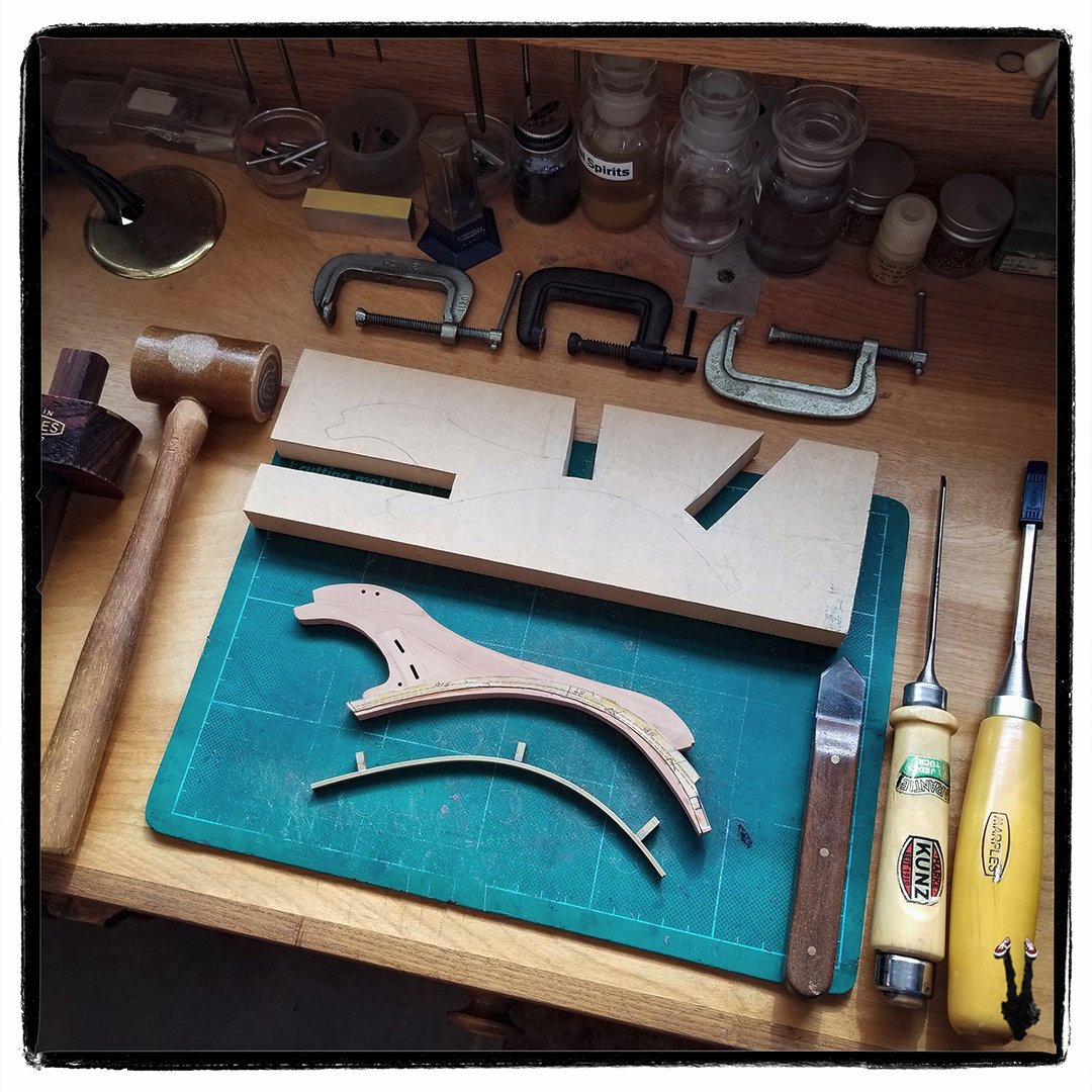
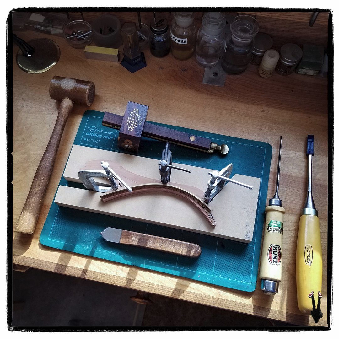
The remaining five bow timbers have now been cut and glued up to the assembly and I'm preparing to cut the rabbets by hand with chisels to accommodate the forward plank ends. The photo below shows the assembled bow section (note vellum pattern still in place with rabbet lines) and two fixtures I prepared for the task. In front is a bass pattern formed to match the curve of the outer rabbet line. It's a piece of brass channel, formed in a small rolling bender. Three clamping feet were then machined and soldered into place on the backside. In the background is a piece of 3/4" T. MDF with channels cut to accommodate the clamps. This serves as a baseboard to keep the bow section stable and flat during cutting. The next photo shows everything set up and clamped in place ready for cutting the rabbet on the starboard side. Everything can be flipped over to cut a matching rabbet on the port side. First step is to scribe a line along the pattern with the marking knife which will help to accurately position the chisels.