Patrick Matthews
-
Posts
406 -
Joined
-
Last visited
2 Followers


Recent Profile Visitors
3,940 profile views


-
 mtaylor reacted to a post in a topic:
Wood deck on steam tug
mtaylor reacted to a post in a topic:
Wood deck on steam tug
-
mtaylor reacted to a post in a topic:
Wood deck on steam tug
-
mtaylor reacted to a post in a topic:
Wood deck on steam tug
-
mtaylor reacted to a post in a topic:
Wood deck on steam tug
-
mtaylor reacted to a post in a topic:
Wood deck on steam tug
-
mtaylor reacted to a post in a topic:
Wood deck on steam tug
-
 Thanks. It's actually my understanding that joggling/nibbling has everything to do with allowing a trunnel to be placed near the end of the plank without risk of splitting a narrow end. BTW, for both Decker (an all wood tug) and Brooklyn (a steel tug with a wood deck), the deck planks are laid over beams, with no subdeck. Decker will be fastened with trunnels, and Brooklyn will have counterbored and plugged holes, with bolts fastening the planks to the beams' flanges.
 -
OK, did my searching here and found: Clear! Thanks for the help everyone, it's been a blast.
-
And why no joggling here? My guess is that the steep angle of approach means the cut plank ends aren't "too" pointy, therefore joggling isn't needed to allow for secure attachment close to the end. A more slender yacht will have a shallower approach & sharper ends, so joggling is called for. I think I've seen a rule-of-thumb for this... anyone have that handy?
-
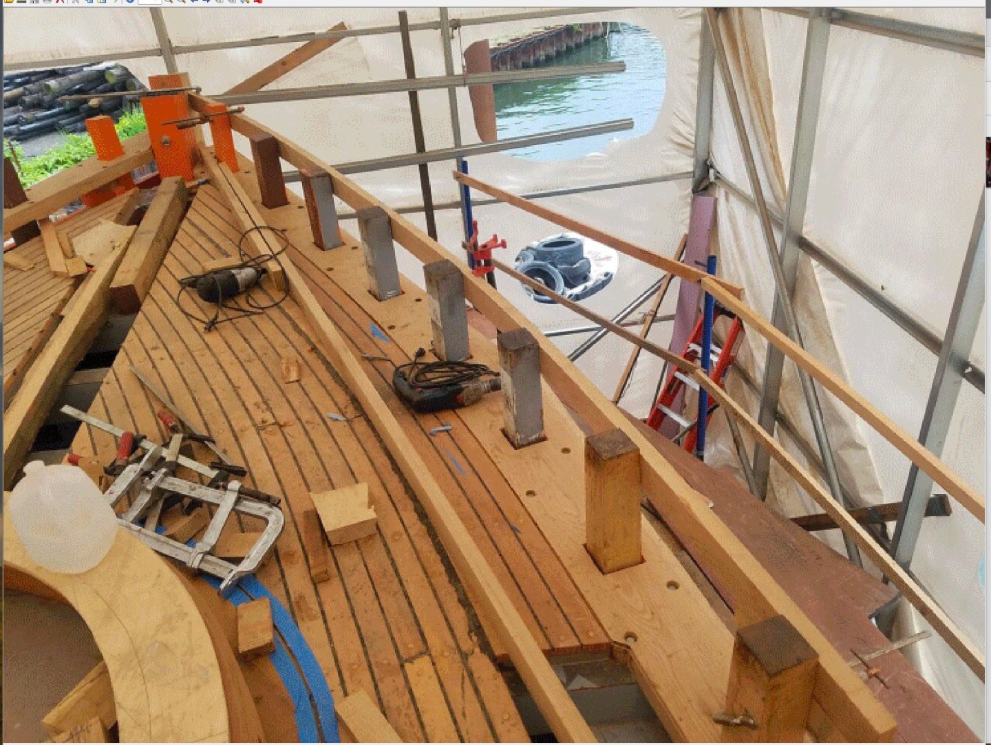
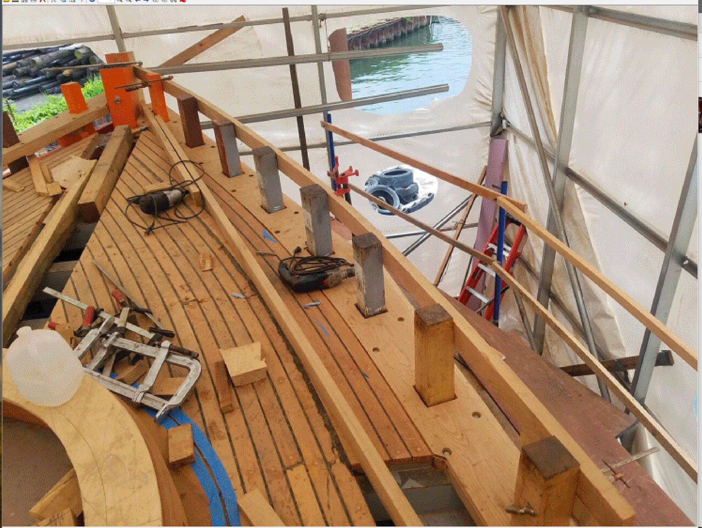
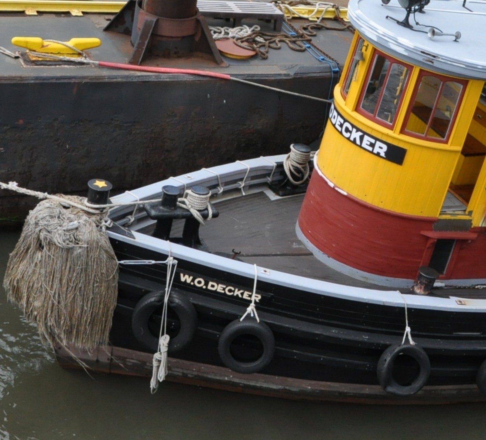
And here is Decker's foredeck during restoration. Hmm, I have to assume this is being done in a prototypical fashion? And nothing like Brooklyn's 3x3 deck planks!
-
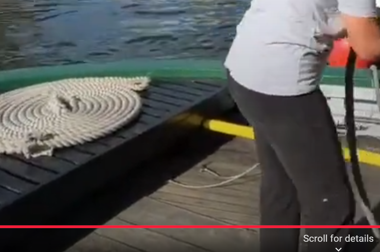
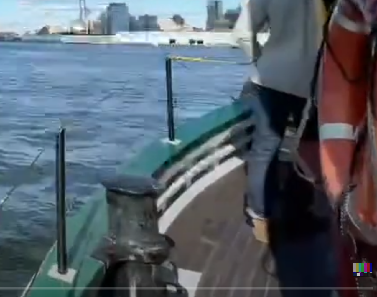
Well, I found a video and a still of W.O. Decker that show: - Planks curving to follow the deck edge; - Apparently NO joggling at the king plank, just pointy-ended planks. I wonder if that's the original layout?

-
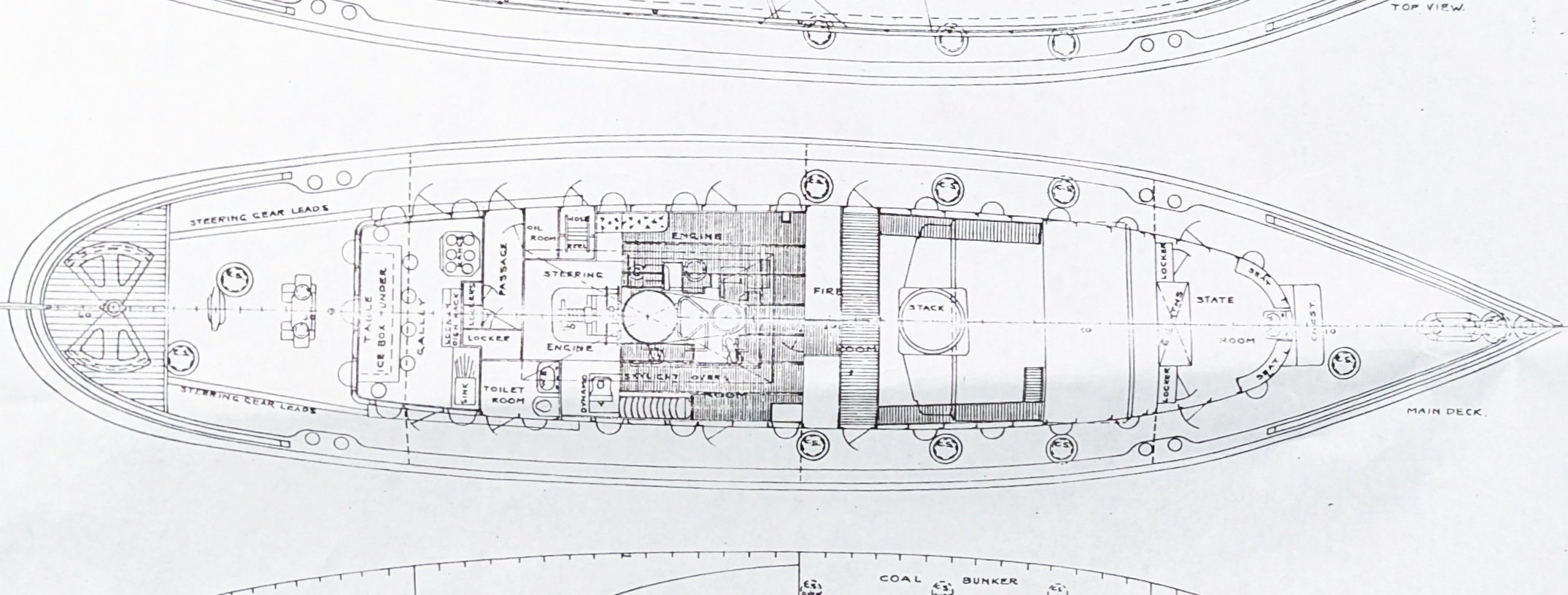
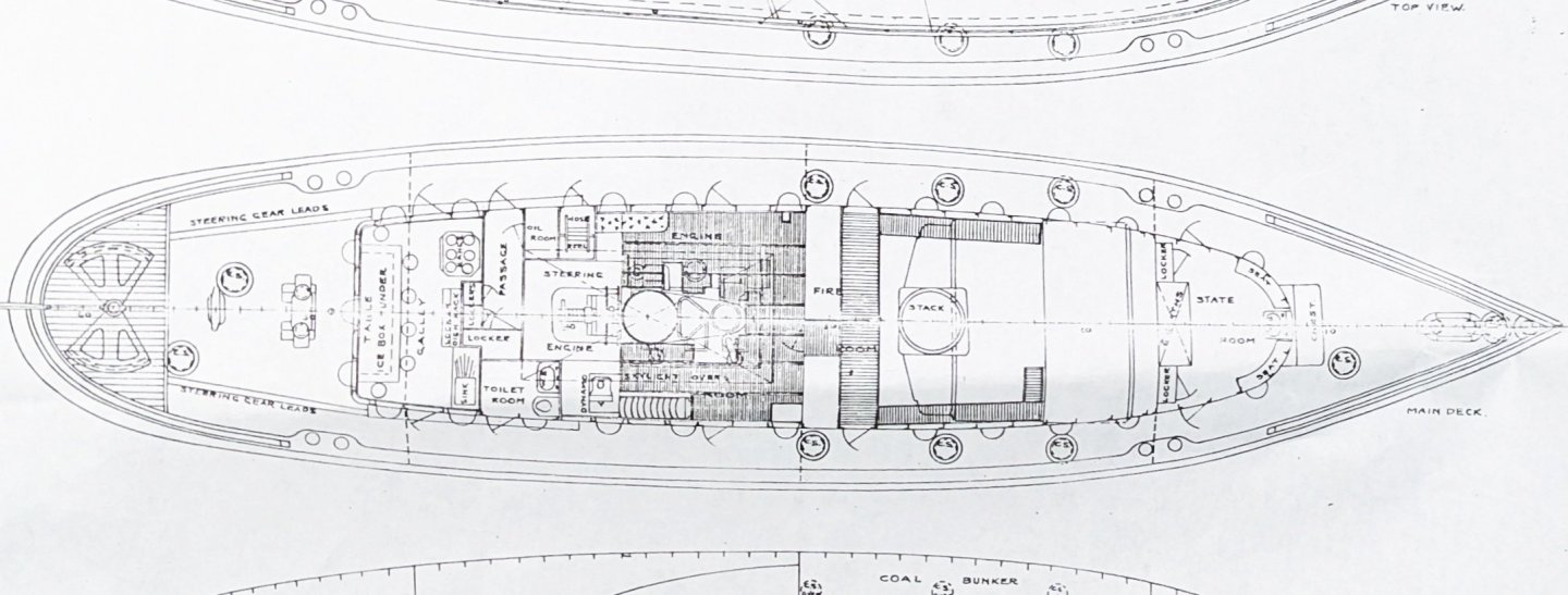
I'm attempting to do a more-correct version of the Dumas Brooklyn tug, and am stuck on the deck. Brooklyn (designed 1910) had a steel hull and steel deck beams, but an all-wood deck. The kit would have us scribe plywood sheet with a straight fore-aft planking pattern. Doesn't seem right. Brooklyn's deck house sides "parallel" the deck edge in plan view, and the one cross section view we have from the original plans show 3x3 pine deck planks between the waterways. (Is the beveled plank adjacent to the deck house also a "waterway"?). Anyway, this suggests that the planking would follow the deck edge curvature over the fore & after decks, which leads to joggling at a central king plank. But I have found no plan or photographic evidence that this was done on tugs of this era. Anyone have better info before I go and joggle a whole bunch of planks in vain?
.thumb.jpg.529c2bb7f8cfae04268804159b7fa61a.jpg)
-
The complete build log is on RCGroups https://www.rcgroups.com/forums/showthread.php?2316931-PILAR-in-1-12 Hope to see pics of yours!
-
Atlantis by Thistle17 - FINISHED - Robbe
Patrick Matthews replied to Thistle17's topic in RC Kits & Scratch building
Sorry I missed your post! Email or PM will get my attention faster. Let me know if help is still needed. -
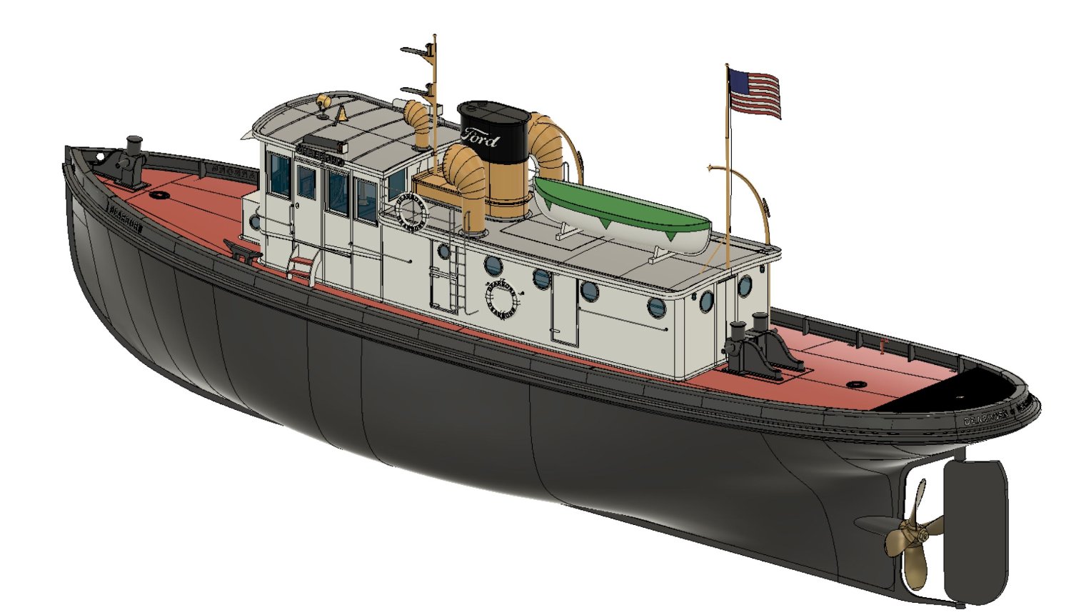
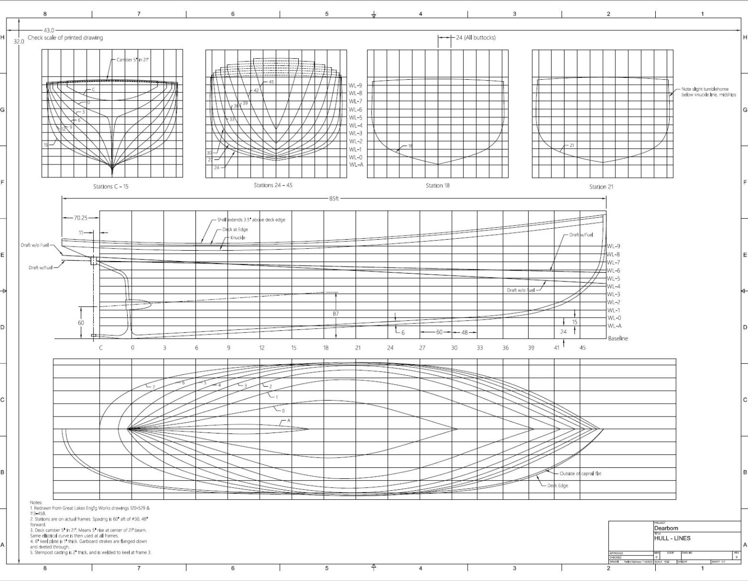
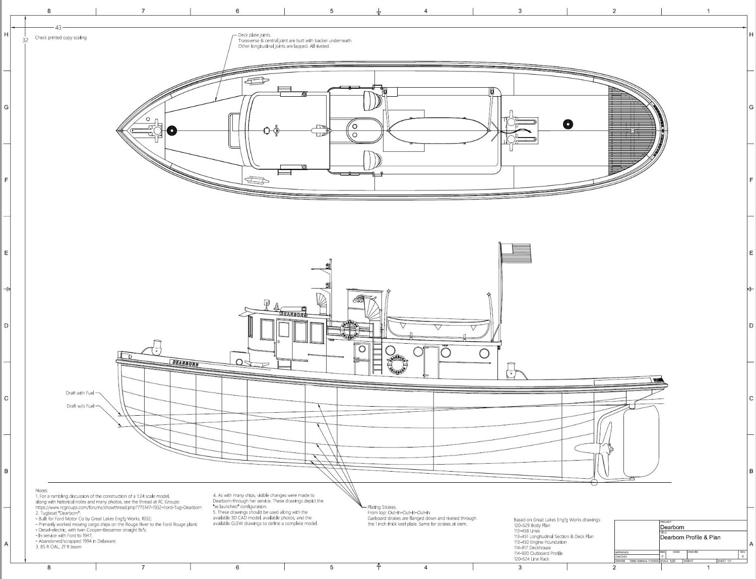
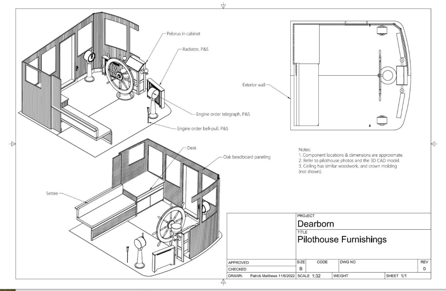
Another CAD model posted on Grabcad for free download- my favorite tugboat, Henry Ford's "Dearborn". https://grabcad.com/library/tugboat-dearborn-1 This is the one I tried Delftship on... but gave up and went back to Fusion360.


-
- 3
-
-
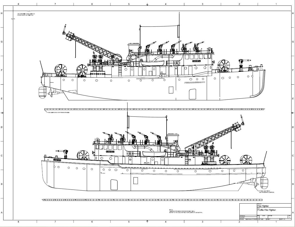
Very nice & complete work! Yes, my goal is to document vessels in a manner useful for modelers. I'm not creating 3d printable files. But my documentation includes 2d drawings as well as a 3d CAD model. The cad model can be used directly, or examined to better understand my abbreviated 2d work I do like the DS lines drawings, and that's another area that F360 erects unnecessary roadblocks... But I'm finding ways to work around those too. See my Fire Fighter model for example: https://grabcad.com/library/fire-fighter-fireboat-1

-
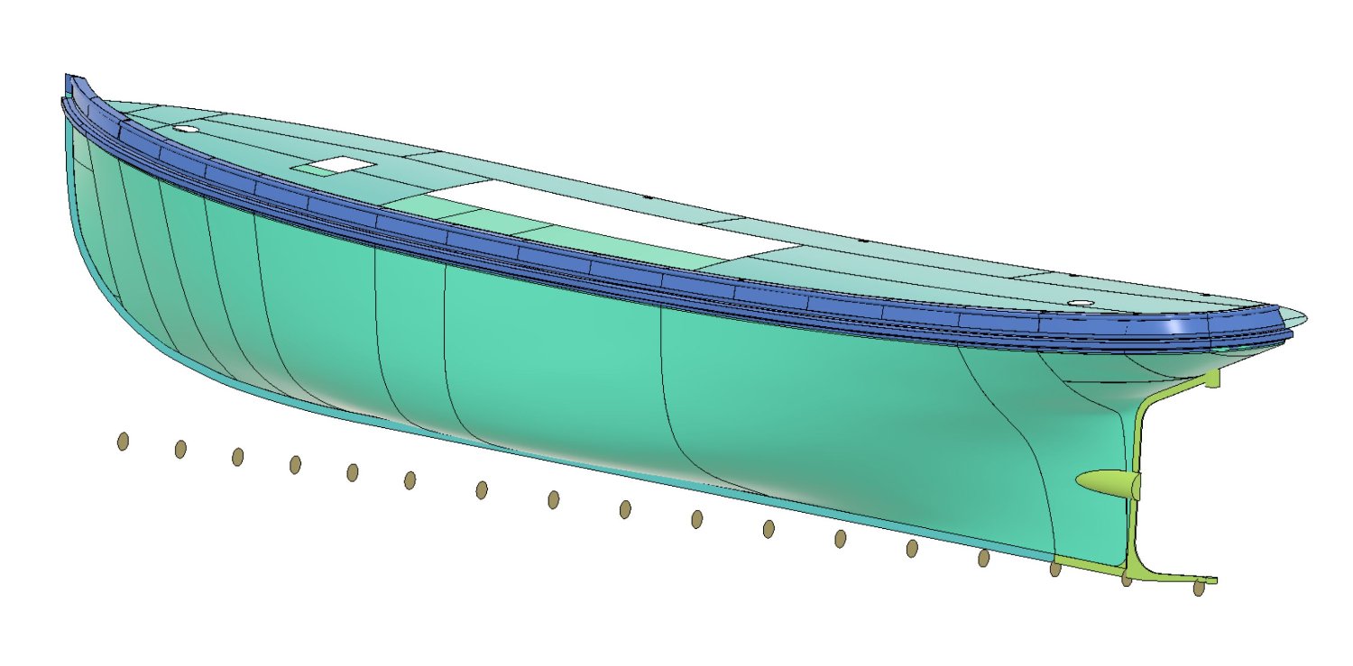
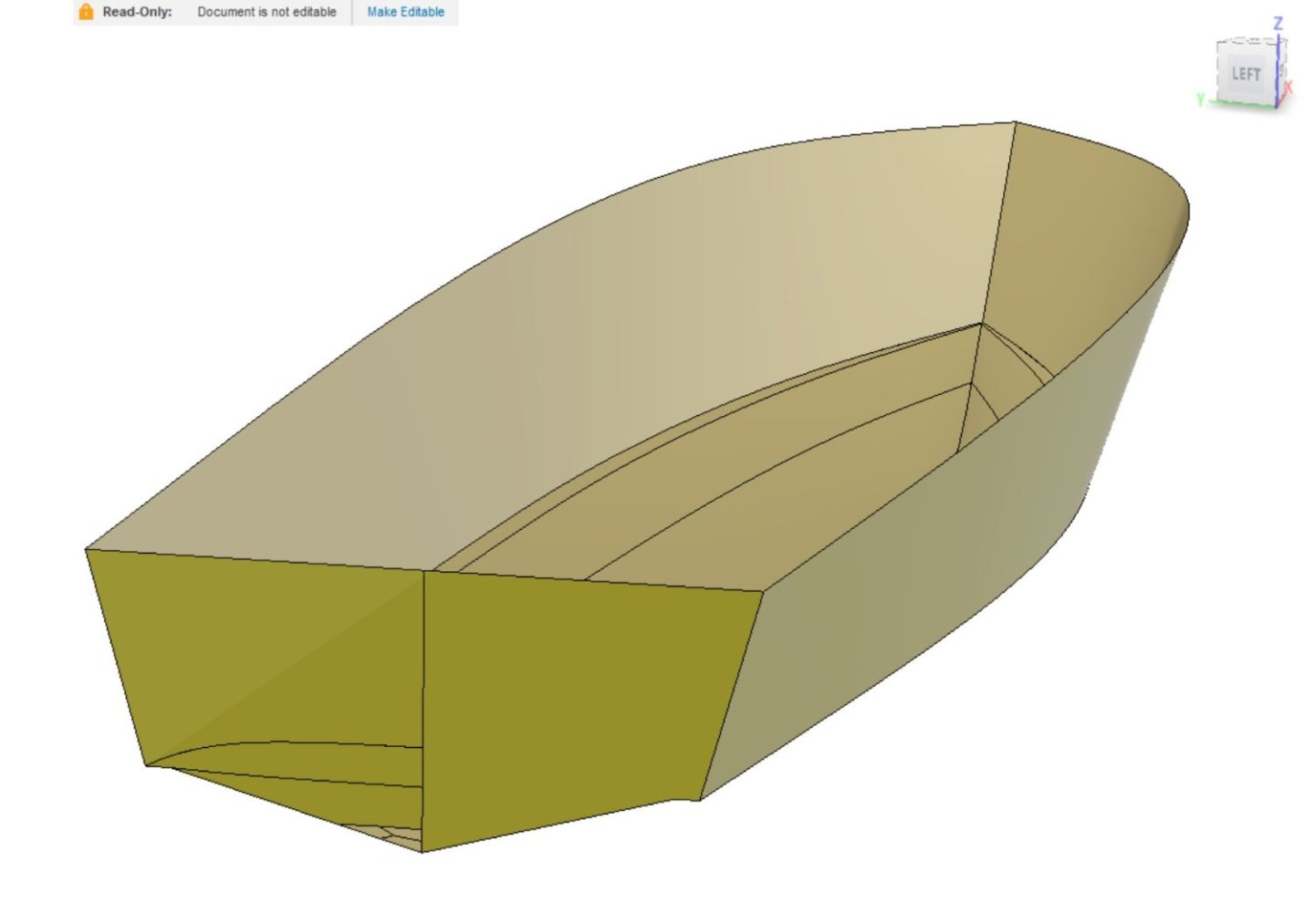
Nope on the 3D DXF. That results in a mesh not unlike an STL- points joined by straight connectors, resulting in a faceted surface. It is NOT a smooth curvy surface. The IGES export is smooth & curvy... I just don't know if the entire side of my hull with its compound curved surfaces comes out in one patch or not. Why do this? Because while Fusion 360 can be a pain for creating lofted hulls, it's a champ for making all the other details. And it has history, which is priceless in large complex models. So if I can make a correct hull in DS, I'd just export the shape to F360. But as I detail above, that subdivided surface from DS using a control mesh is WRONG, and it requires a lot of tweaking to correct. Now, with much gnashing of teeth, I have been able to create a reasonable lofted hull in F360... so it's just a matter of which path is less headache. My F360 generated hull:

-
Thanks! My biggest question regards the IGES output, only available in the Pro version. They told me it can output many, maybe hundreds, of surface patches, which would likely look like a mosaic when used in other CAD software. But if, for example on my tug hull, it comes out as smooth single patch for the main surface, that would be fine. They sent me a sample IGES file, but it was of a simple developable hull, so not really a test of this feature. The transom (port) was fractured, but I stitched the surface patches in Fusion360, and it all merged nicely (stbd).
-
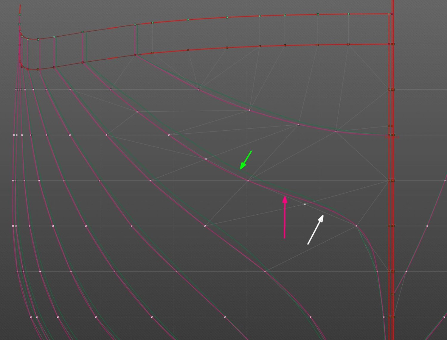
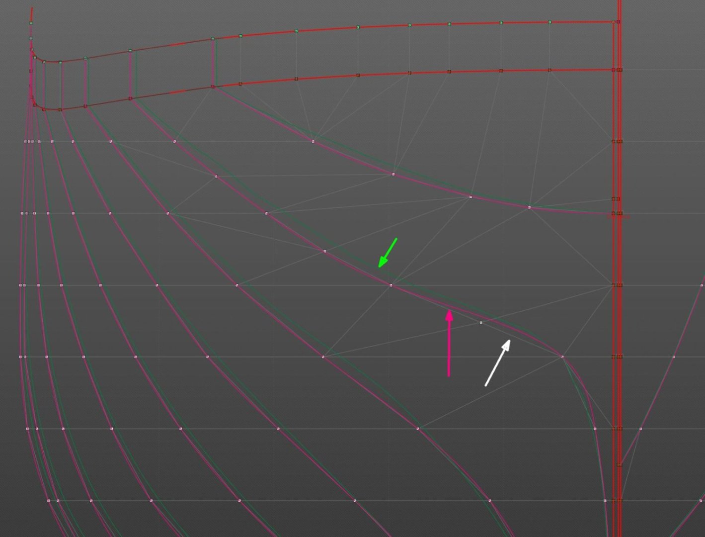
Here's an end view showing some of these features: White: Original control points and the control mesh with its straight Tinkertoy connectors. The control points lay on the proper body sections from the lines drawing. Green: Body sections cut through the DS developed hull surface... they miss by a lot. Even at the deck edges. Pink: Nice curvy marker curves that DS draws for the second import of the original control points. These markers are the target, I need to move the green lines to match them. To move any one point: Click on it, and you can enter new numbers or use the little arrow to move the point by set increments, very handy. Move each and every one this way to drag the developed sections around.
-
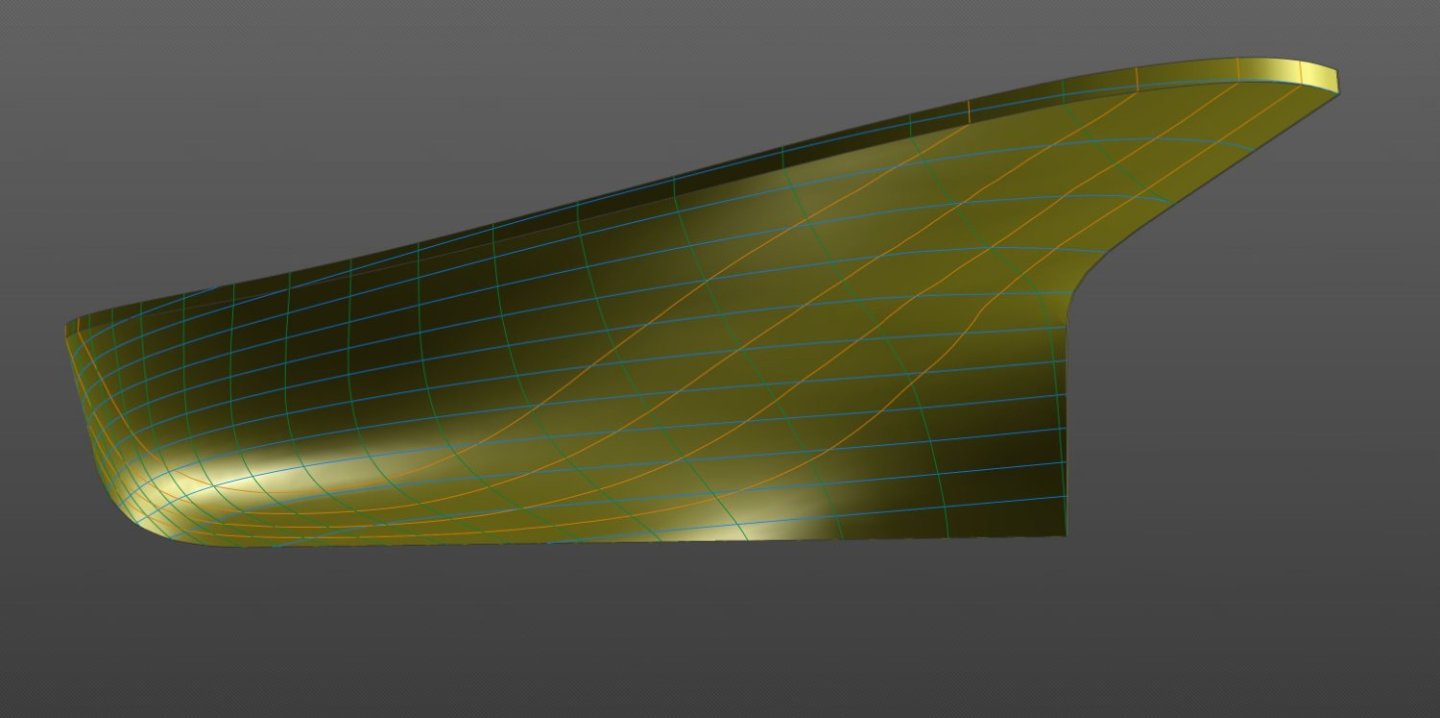
So here's the second most important thing for DS users to know: Lines imported from a lines drawing DO NOT create a hull true to those lines! First most important? It can be fixed. As above: "The developed hull shape does NOT go through the control points, which are input from the original lines drawing... they just INFLUENCE the shape. Fine except it's not, because the developed form no longer matches the original. There must be a work flow that gets the generated shape closer to the desired form." Indeed the DS developed hull cuts corners, it's always well to the inside (concave side) of input curves, except at the "corners". Imagine you have a magnetic rubbery sheet pegged by its 4 corners to the floor, exactly where you want the corners. Then you hang a bunch of magnets from the ceiling, and each magnet is hanging exactly where you want the sheet to stretch and rise to, defining some sort of hill (I'm picturing Richard Dreyfuss building Devil's Tower in his living room). But while the sheet is stretchy, it's not THAT stretchy, and it hovers over the floor but doesn't quite reach the magnets. Oops. That's what we have in DS, with the developed hull not reaching the input points. How to fix it? Just keep raising the magnets until the sheet rises to the proper place. In DS, I did this, though there may be more efficient ways: 1. Import the control points once to define the control mesh and its resultant malformed hull. 2. Import the control points a second time as "marker curves". Markers are static curves, immutable, and they serve as references of where the original control points and desired hull sections are. 3. In an end view, compare the developed body sections (which are wrong) to the desired shape shown by the marker curves. Now start moving control points sideways or vertically to slowly pull the body sections towards their markers. Yes, this modifies the original control points and mesh! 4. Note that this is iterative... moving one point affects the adjacent surface faces, so you'll need to sweep back and forth over all the points to get everything close. 5. Also note that the four edges of your rubber sheet between the corner pegs were also pulled off the floor when the magnets started lifting the center. Same thing in DS- the edges at deck edge and keel also have moved out of place. So the adjusting exercise needs to address those too. I did this for my tugboat hull, and while it still needs some adjustment, it's much closer to the desired shape now (below). More: While you can get close by doing this, you can also turn on curvature displays to better smooth (fair) your new shapes. I haven't done this yet, may not need to for my present purposes. More #2: The Pro version of DS has an "automatic fairing" tool. I'm not sure how this works, but it could be of help.
-
I did receive replies from DS HQ: 1. The forum is not broken, new posts are moderated. But still, not so much recent activity, which is curious. 2. Hull surfaces exported as IGES are "smooth parametric surfaces, but please keep in mind that the exported hull can consist of many (sometimes hundreds) of such surfaces." So it's not clear yet whether that would look like a broken mosaic when imported into my CAD.
.jpg.46b7ba5600abf95735f60d7b863b26c6.jpg)