oakheart
-
Posts
518 -
Joined
-
Last visited
Content Type
Profiles
Forums
Gallery
Events
Everything posted by oakheart
-
 Yes there is a foot with it, have a look at photos of the Delta scroll saw, it just has a rod/bar that is attached to the rear frame, with another rod that holds the foot. I personally never use it, I find it gets in the way, as long as you use your fingers to hold the work down there should not be a problem. It's just a matter of practice. also fine blades are better than coarse in keeping the problem at bay. Tim
 -
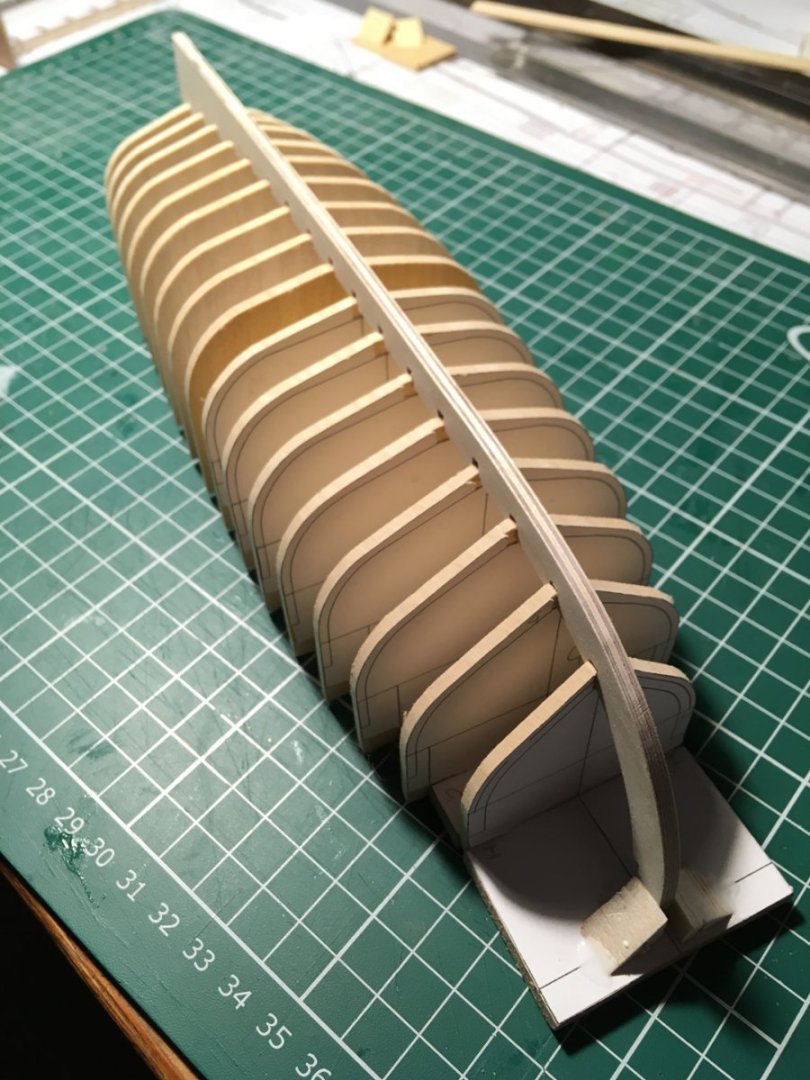
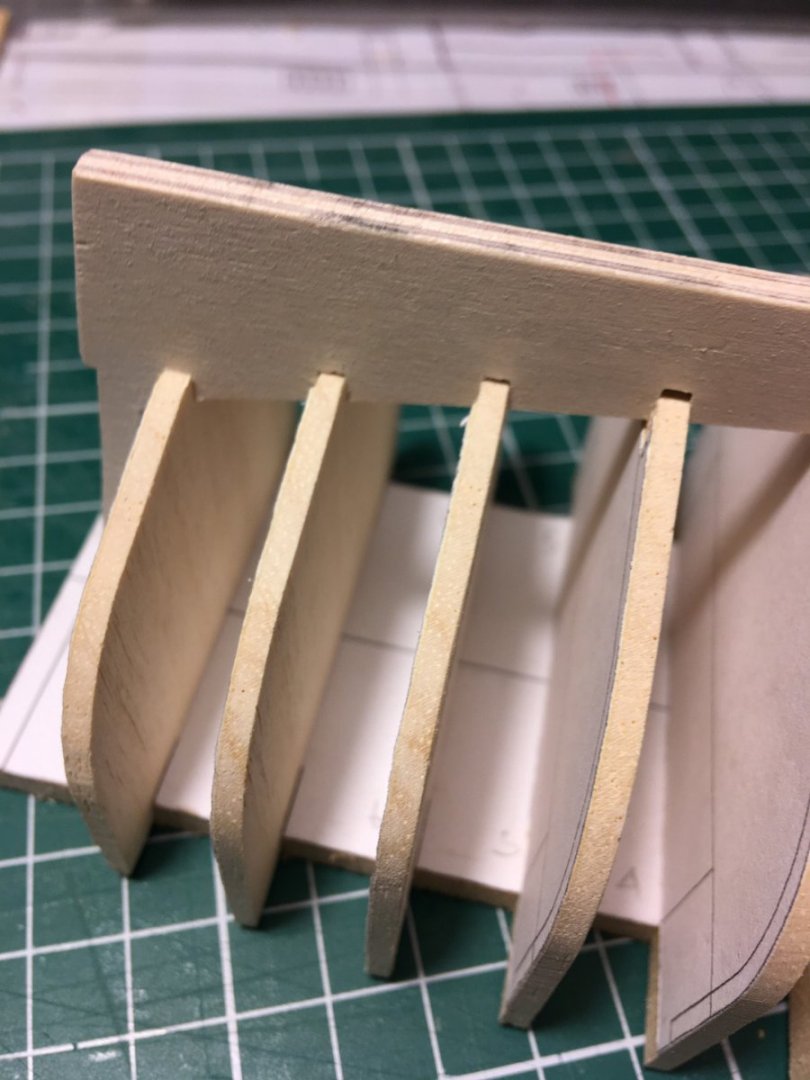
So after my tea break here they are, a landmark for me. This is with the plywood keel that I will use while fairing the frames. It's difficult getting all of the frames fitted into the keel, a bit like having taken a clock to bits and trying to get it back together I think that will do for today. Tim
-
That looks like the one Tim
-
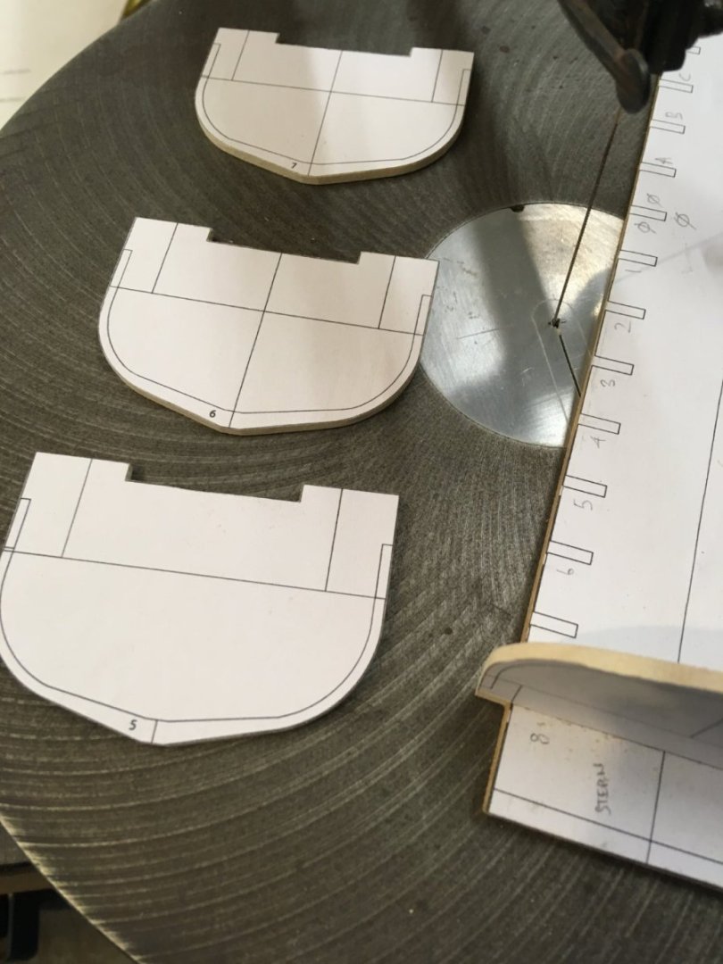
This morning I realized I was getting ahead of myself, I need to cut the frames and base first, then do the planks. It's easy to get over excited and get carried away. Well I find that I do. 🤪 So the rest of the frames are cut out, having a cup of tea then I will sand them to size. Tim
-
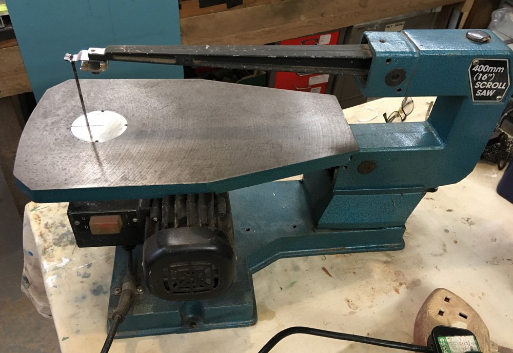
Hi Riotvan, It does tilt. Just checked again - there are no markings at all not even on the motor! Runs and cuts okay, picking up on Jaagers comment about the up/down problem, there is a sort of hold down fork but no brackets but you could easily cobble something together. For PnP the size is 55 x 30 x 22 cm and weight is probably closer to 30 kilos, ( my Delta is quoted as 30 k ) I could wrap it in corrugated cardboard and bubble wrap. Parcelforce are quoting £15 for 2 day delivery Should we take this offline, not sure what the rules are on here as I am still a new boy. Tim
-
So I just made a drum from some aluminium rod about 10 mm dia. used some sandpaper from a 120 grit sticky back sanding disc cut to size. Thanks for tip on speed. When I ran it fast and tried to hog off too much, the rod heated up, the sticky back melted and let go. so I cut a new piece of the sandpaper, slowed the speed down to about 1200 rpm, took much lighter cuts of about 0.1 mm per push / pull through. The useful thing about using the mill table is I can tell how much I have dialed down the thickness for each pass. It takes about 5 'cuts' to go from 1.5mm to 1.0 mm thickness that's much better, I do have to be careful to make the push / pull consistant or I get dips in the plank. I definitely need to get the dust collector fixed uo on this set up. I know what I am doing tomorrow. TIm
-
Thanks for the encouragement. I will do some testing on the speed of the drum as well, thanks Tim
-
Mini Mill as sanding thicknesser, proof of concept. A quick test using a 12 mm Dia. Dremel sander drum some ali. angle and a band saw cut pine strip. Well it works with a few basic things that I need to address: The base of the drum needs to be below the bottom edge of the strip or it leaves a ridge. The drum needs to be straight sided - the Dremel tool has a slight bulge to it. The drum needs to be wide enough to cover the whole strip Even with this very crude setup, using the movement of the Mini Mill table cross slide I could accurately sand down to 0.5 mm It feels very controllable, so now off to make a more substantial drum and angle guide Then test with different grits. Thanks for the tips guys. Tim
-
It's an old, no name saw with a cast iron table, single speed and takes pinned blades. There is a set of adapters to take pin-less blades It will be expensive to send from Hereford as it weighs a ton ( well about 25 kilos ). There are 2nd hand saws on Ebay quoting £30 delivery. I suppose it might be worth £50 ? Not having a manufactures name makes it difficult to look up Tim
-
Thanks, Good to know it does work, I have some aluminium bar which I could turn down in the lathe for a drum, stick some sandpaper on it and give it a try. Having mainly worked with metal for the last few years, the metal bar seems easier than the MDF for me. Does the diameter of the drum make a big difference ? I guess I should make several sizes ? Tim
-
With the cutting of the frames well underway, I now have to start thinking about the planking. I have some 0.8mm basswood sheet which I will use for the as sailed version. But the 1.5mm thick Cedar strips I want to use on the raw wood version, need to be reduced down to about 0.9mm to be accurate for the 1:24 scale. I don't have a thickness sander, but I do have a mini mill and I have seen people cobble together a sanding drum on a pillar drill to do thicknessing of strips. It could work using the mill spindle head with a shop made sanding drum. Question : has anyone done anything like this? I should have known it would be like this, one thing leads to another, a very deep rabbit hole... Tim
-
That looks like a lot of hard, accurate work to me, I'm surprised it's not stained with spots of sweat, given the temperatures down there With my build 'old habits die hard' I'm taking the easy way out and using a single frame, hats off to you for going for the hard way. Tim
-
The Cornish replica had to use a laminated stem, they could not find a big enough piece of bent timber, all of the oak for the futtocks and floors came from just up the road from me here in Herefordshire. Tim
-
All very neat and tidy, I'll have to pull my socks up. Tim
-
Hi Allan, not dense at all, yes its to locate and strengthen the frames. As you say it will not show. That's also why I am being lazy and making the frames in a single piece, rather than like CrazyCraig who is making floors and futtocks. At our scales that would get really fiddly, with the floor boards in place this difference will not show. Tim
-
I did the frames for my 85 ft Harbor tug on a scroll saw. You can pick them up pretty cheaply locally, our club here in the UK has one looking for a home right now. Shipping would probably cost too much. Tim
-
Difficult to tell from the photo, is that stem laminated ? Tim
-
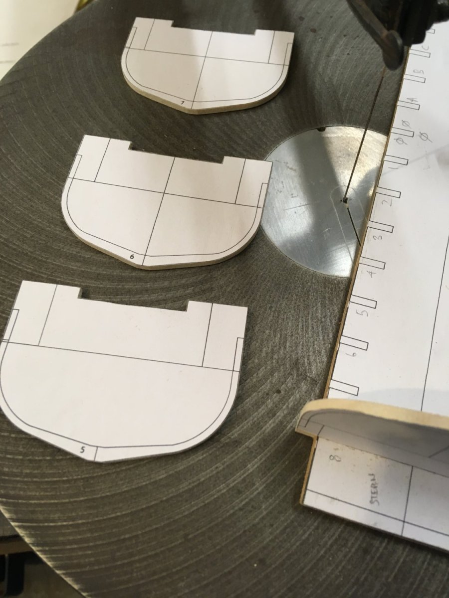
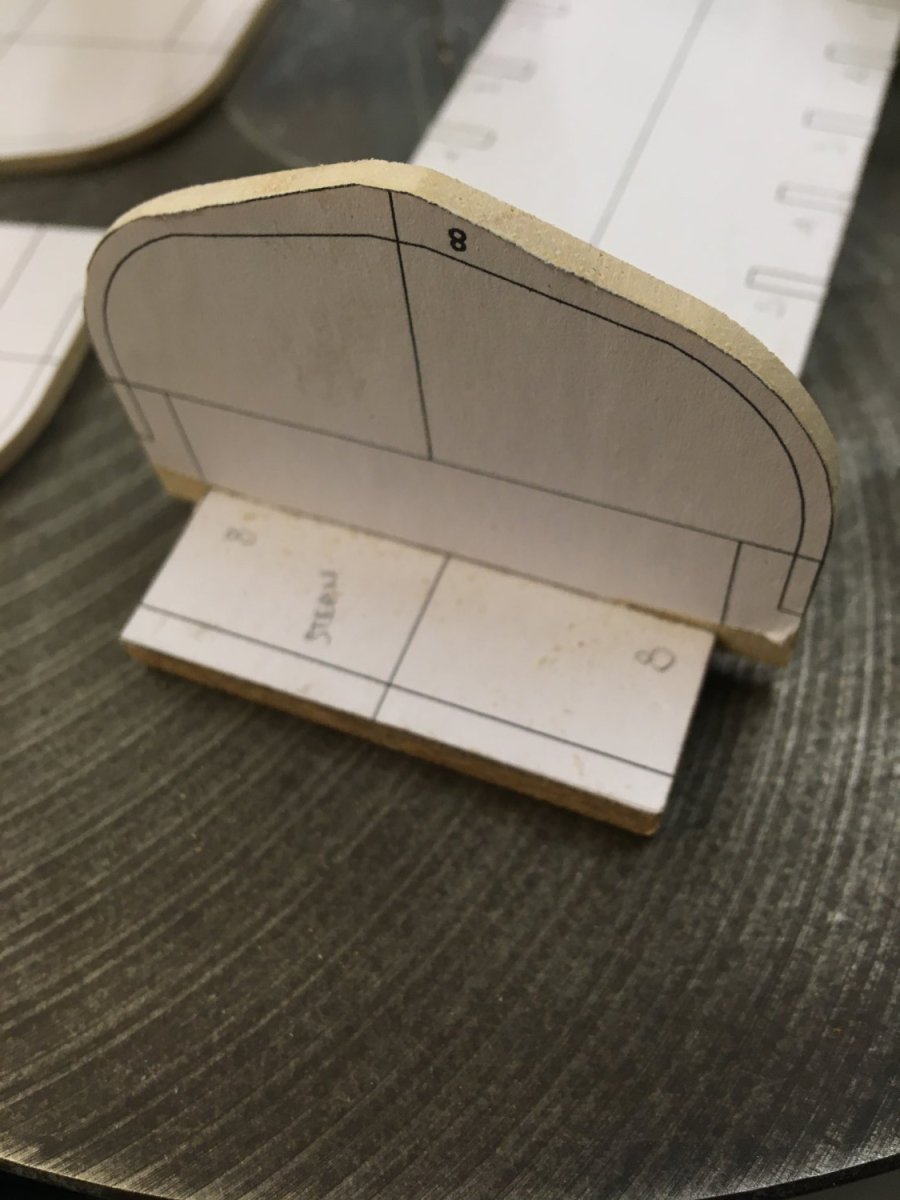
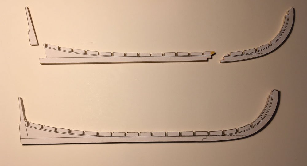
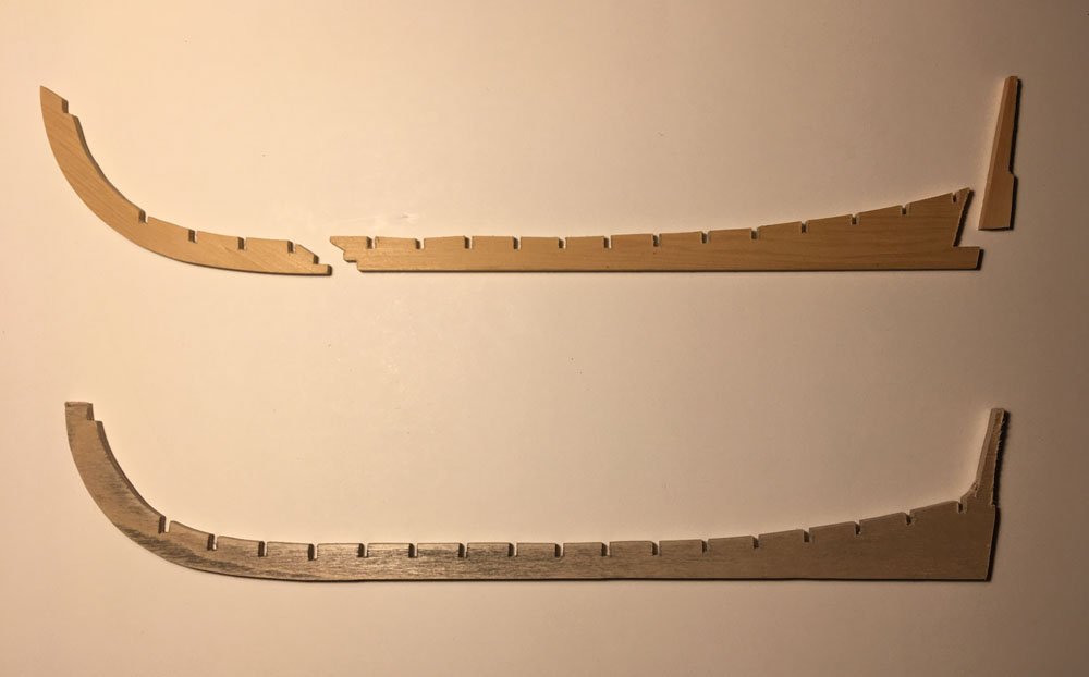
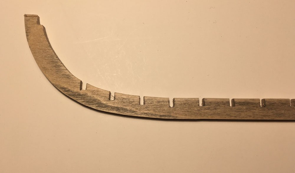
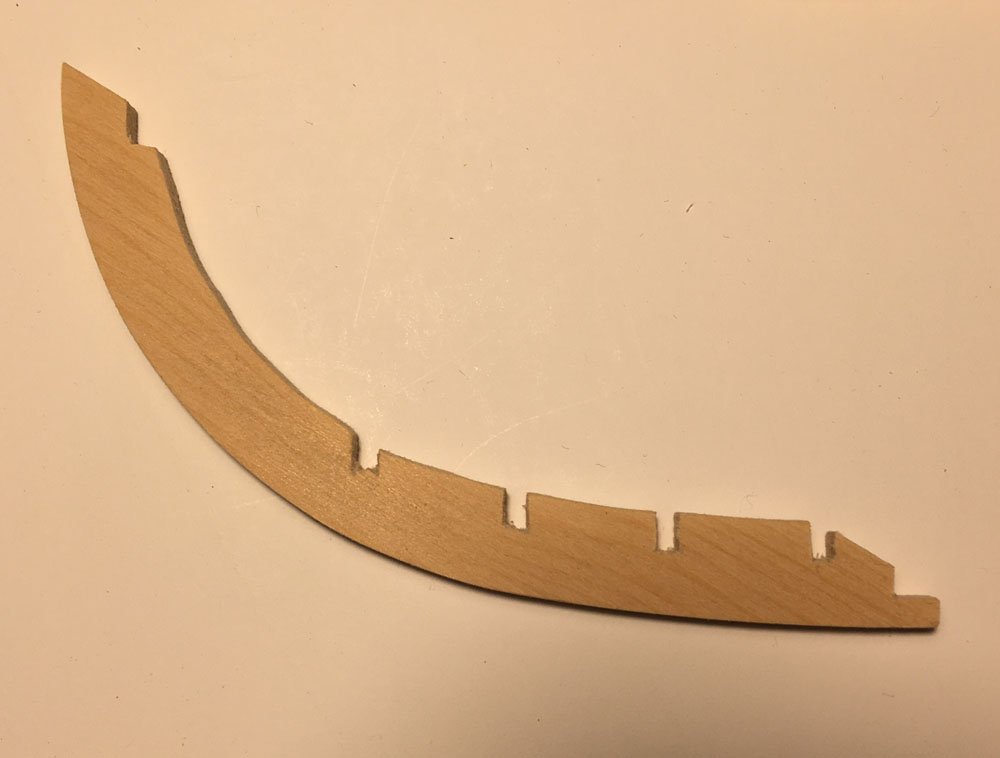
Managed to get two versions of the keel cut today. One in plywood the other in cedar. Learned that it's not a good idea to try and do this kind of work in a mainly metal workshop. Pick the wrong piece of sandpaper ( wet-n-dry ) and the wood gets very grubby ..... lucky it was the ply version. I will use the ply version while fairing the frames. It was good practice for cutting the 'good ' version Pleased with the good cedar version it all needs careful fettling now. It's really easy with this soft cedar to round over the edges, I will have to watch that, I'm too used to brass which needs a lot more elbow to make it conform Tim
-
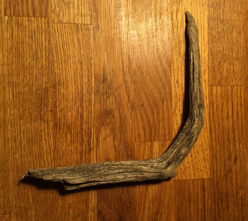
Talking of timber for making ships about 15 years ago I was talking to a park ranger at Croft Castle in the UK and he told me a story, about the trees on the Ancient Tree Walk. The trees themselves are thought to be over 400 years old. The story is that the chestnut trees were grown from sweet chestnuts that were taken from the captured Spanish ships at the time of the Spanish Amada. It is also said that a planting regime of Oak Trees (English) and the Sweet Chestnuts (Spanish) in the grounds at Croft represents a battle formation during the Spanish Armada. He gave me a twig from one of those trees, about 7 inches long it looks the part for the stem, but there is no way I could use Spanish chestnut on the model of the Bounty Launch. I do that walk frequently, I need to look for an Oak twig …………. Tim
-
Believe me I have looked round the garden for suitable twigs or branches......... Tim
-
I don't know how I missed this new build log. But I am here now. Nice going Craig Tim
-
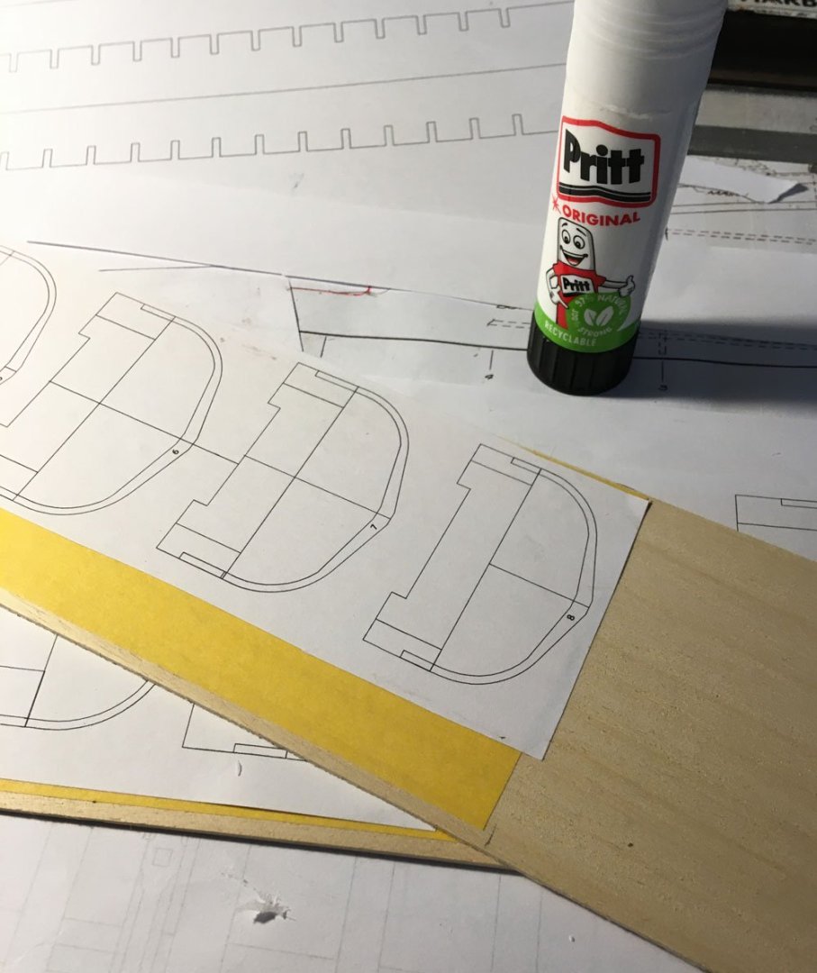
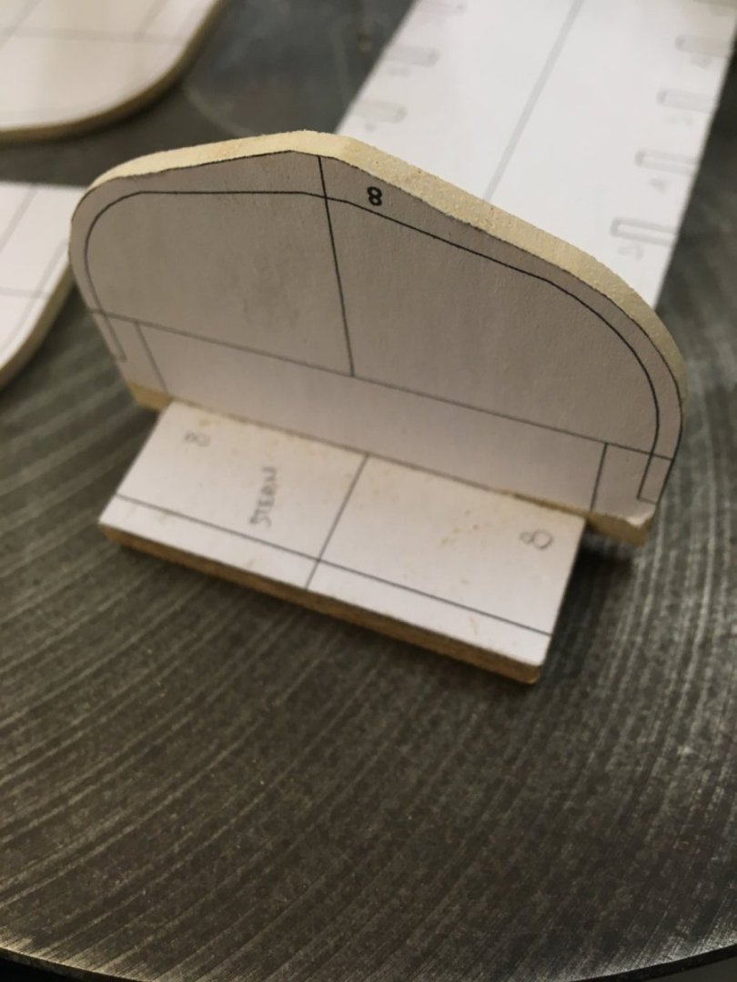
Finally got some time to do a bit of boat building. Paper templates are glued in place, the wide smooth masking tape from 'Wilkos' is great for this, I also use it with CA to hold parts on the CNC machine. Frames / molds cut out and test fitted to the new base/jig These frames are to see if the sheet Obeche I have works for these frames. I am a bit worried it may not be robust enough. I can see why they used floors and futtocks on the real thing, that way you can have the grain running in the correct direction for strength That may have to be plan B. I can see that's what Glen is doing - but then he must be crazy....... The Tape / Pritt-stick worked well, no lifting or buckling, so I will be using it on the rest of this part of the build. Tim
-
"fare winds and following seas" to you too Aiken, I am a new boy here and have found it a wonderful place to learn and make new 'shipmates'. Tim
-
Thanks Allan, the clamps came from ebay, about £3 for a pack of 50. I added the coffee stirrer extensions instead of the metal loop in the hope that will it not bruise the wood. The test shown is on my Version 1, rejected frames and molds with a stray piece of plank sized wood. This is not the real thing.... thanks for the link to the article. Over the next few days I hope to get the latest version cut out, the printer is clunking away printing out the drawings ready to be pasted on the wood I am going to try masking tape and pritt-stick to hold the paper template in place. Masking tape on the wood, pritt-stick on the paper template, the masking tape comes off cleanly and I won't have to clean the pritt-stick off the wood. I will let you know how it works. Tim
-
Just tried shortening them, it made a big difference to the hold down. This place is amazing, I could have spend days tinkering and trying different things, just ask and someone will help. Thanks again Tim