
MORE HANDBOOKS ARE ON THEIR WAY! We will let you know when they get here.
×


oakheart
-
Posts
518 -
Joined
-
Last visited
Content Type
Profiles
Forums
Gallery
Events
Everything posted by oakheart
-
 Thanks Christian I hope to do a plank on bulkhead scratch build of a Cutter as used in the South East Kent area of the UK The Rattlesnake was built at Folkestone a town I know well. Any information I can get will help with drawing up my plans. I have chopped up the Danish drawing and imported it into Fusion 360, next I start tracing the station lines for the bulkheads. It's the same as I did for this launch model, just bigger.. Tim
 -
Hi Christian You developed some drawings for the Alert http:// https://modelshipworld.com/topic/4993-naval-cutter-alert-by-anobiumpuncatum-scale-132-pof/#comment-144239 Would it be alright if I used these to help me develop my 1:64 scale version of the Rattlesnake? Tim
-
Thanks Christian, I will watch out for the differences. I have the drawing from RMG as well as the one from the Danish archive. I really should finish this build first, but there is no harm in setting out plans for a new build, is there ? Tim
-
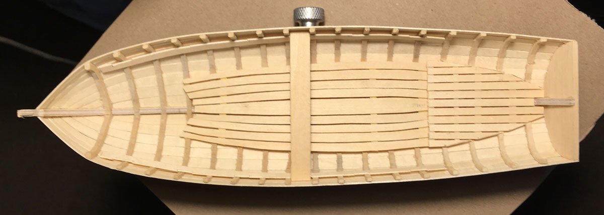
Hi Allan The rear platform sits about a scale 6" off the keel. I will redo the main floor planks based on Craig's comments above If the kudos was really meant for me then thank you, ( now my head really will swell ) Sort of lost focus over the last week, back now and will try and get some bits done on this build Tim
-
So here is my interpretation of the floor, does it look right? needs some cleaning up round the edges. Tim
-
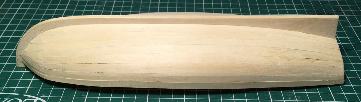
I have found some 25mm ( 1 inch ) dia. ready made sleeves. I now have to make something that will fit in the chuck and spin true. The workshop is too cold today, so will work on the hull instead. Tim
-
The thickness sander I cobbled together for the cedar planks needs rebuilding, he double sided tape on the sandpaper keeps letting go so the next hull is on hold. Instead, I have started on the floor and internal parts on the Basswood hull. Not sure of the correct flooring layout, so have copied what I can see in the photos of other builds I will add photos later, just having my morning coffee. Tim
-
Wow - that is impressive. Nice work indeed. Tim
-
3D cannon barrels
oakheart replied to allanyed's topic in CAD and 3D Modelling/Drafting Plans with Software
Hi Allan to answer your questions ship : HM Cutter Rattlesnake date 1777 British Royal Navy Thanks for the heads up on the dates Tim -
3D cannon barrels
oakheart replied to allanyed's topic in CAD and 3D Modelling/Drafting Plans with Software
Hi Allan Just found this page, really interesting. https://www.arc.id.au/ArmstrongPattern.html I will be using it to find the shape for an 18th C 6 pounder Tim -
Hi Craig, thanks I had not seen that, it will be very useful. Interestingly the access stairs are shown running fore and aft, on ZAZ7910 they are shown sideways. It would make no difference to a typical hull model, but it shows the difference that could happen with different builders What is great is that you can read the text, I have transcribed the mast sizes Rattlesnake Dimensions of masts Main mast 78’ 6” 20.5” dia BowSpreet 38’ 6” 18” Boom 58’ 10” 12 5/8” Gaff 40’ 9” Storm Gaff 17’ 9 3/8” Top Gallant 35’ 10” 9” Square sail yard 49’ 8” 9” Top Sail Yard 36’ 9” 8 ½” Mizen Mast 38’ 2” 9 ½” Out Rigger 33’ 9” 8 ¼” Yards 30’ 6 ½” Jibb Boom 30’ 8” 7 ½” Driver Boom 27’ 6 ¾” Tim
-
Very nice work it is too. Planking is looking really good. Tim
-
I think that's what I will aim for, it will cover up all my mistakes, with a bit of extra weathering from the journey I think it could look very interesting. Add a bit of dried blood spatter on the inside from those boobies they ate raw. Mind a good deal of that would have been washed away by all the sea water coming into the boat and being bailed out again. Tim
-
Lapwing 1816 Revenue Cutter
oakheart replied to iMustBeCrazy's topic in CAD and 3D Modelling/Drafting Plans with Software
Hi Craig, I made it here, some really nice research. Have you completed the drawings? I am just starting out on my interpretation of the Rattlesnake built at Folkstone ( sister to Alert ) so all of the information gathered here will help me on my way. Tim -
Lessons learned so far: Pay more attention to the early stages. Like cutting and sanding the frames to shape. Do more work on fitting the planks, I did find it tedious to keep putting in on to check, take it off to sand, put it back on bla,bla,bla Try different methods of clamping I need to slow down and not try to rush things. At these small scales I need to learn to use a more delicate approach with my tools. So my thinking is to move on to the next hull build and leave the 2nd fixings of internal details for later. That way I still have my planking skills ( ha. ha. ) fresh. I may experiment with more planks on the next hull, we don't know how many the original had anyway and it should lessen the problem I had with planks not laying flat. The Cornish Maritime Museum full size build used 14 per side, I think maybe they did that for the same reason. Tim off for a coffee and a read of Craig's cutter drawing log
-
Nice work on the cutter, way ahead of me as usual 🙂 I am going to read the whole thread with my coffee. It could be a candidate for a build. I was in Melbourne / Sydney in October 2022 visiting relatives, shame I had not found this community at that time. Did a bit of research into the First Fleet while I was there. Tim
-
Chuck Passaro and others have been singing the praises of Alaskan Yellow Cedar, look for Chucks longboat build log on this site. I then found somewhere in the UK to get some so ordered some. It does look nice and works beautifully. Basswood ( Lime in UK ) carves beautifully with sharp tools but it goes all kind of fluffy / stringy when you sand it. Using a brand new Stanley Knife blade as a scraper gives a really good surface finish. As long as you don't get glue on the surface, It will stain nicely to any wood colour you want. I have a love / hate relationship with it on this build. Tim
-
And there was me looking at your plug method and thinking I must try that as it gave you a good result. Let's see how CrazyCraig gets on with his separate futtocks and floors. Tim
-
Thanks Craig, once my head has settled down, I will do all of the things you suggest. As to what's next as a build ( apart from the my Bounty Launch in cedar ) Do I get a kit or do another scratch ? I am rather taken by the 18th century Cutters. The Sherbourne and Lady Nelson? I think they look kind of dumpy, some would say cute. so possibly an Alert / Rattlesnake much more elegant. The Rattlesnake appeals because I had family from Folkestone ( my Uncle Stan ) As a pensioner I can't justify the cost of the Vanguard Alert kit, it does look nice. Are there others out there? For a scratch there is a good amount of information about both, AntonyUK and others on this site have done drawings for them. I will do some more research and look for information, there are some good scratch build logs on here built from the Goodwin book. Tim
-
I have heard that "we learn nothing from success", can't remember who said it. Thank you for the encouraging words, they help to keep the fire going. Thanks too to all the lurking likers 🙂 moving on, whats next? Thwarts and gunwales I guess. Tim
-
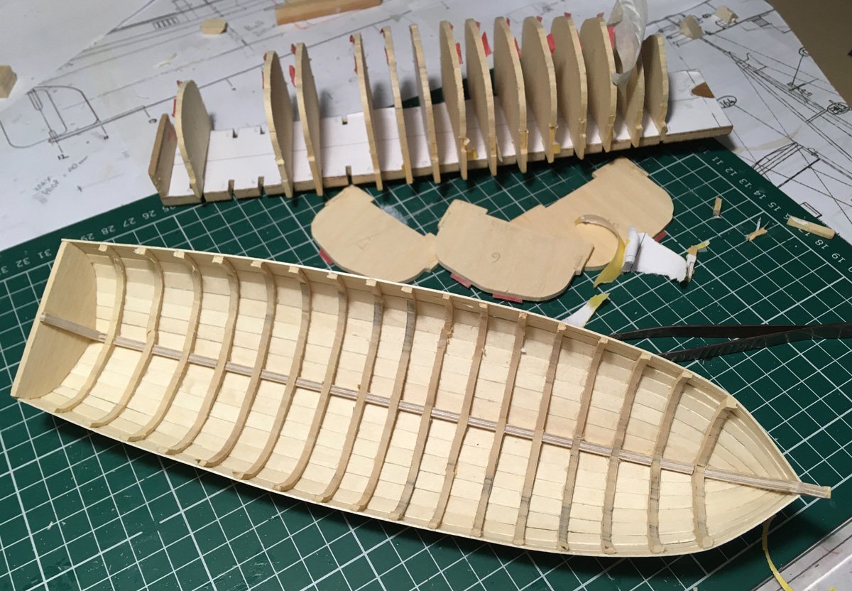
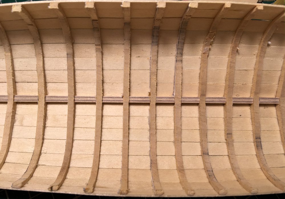
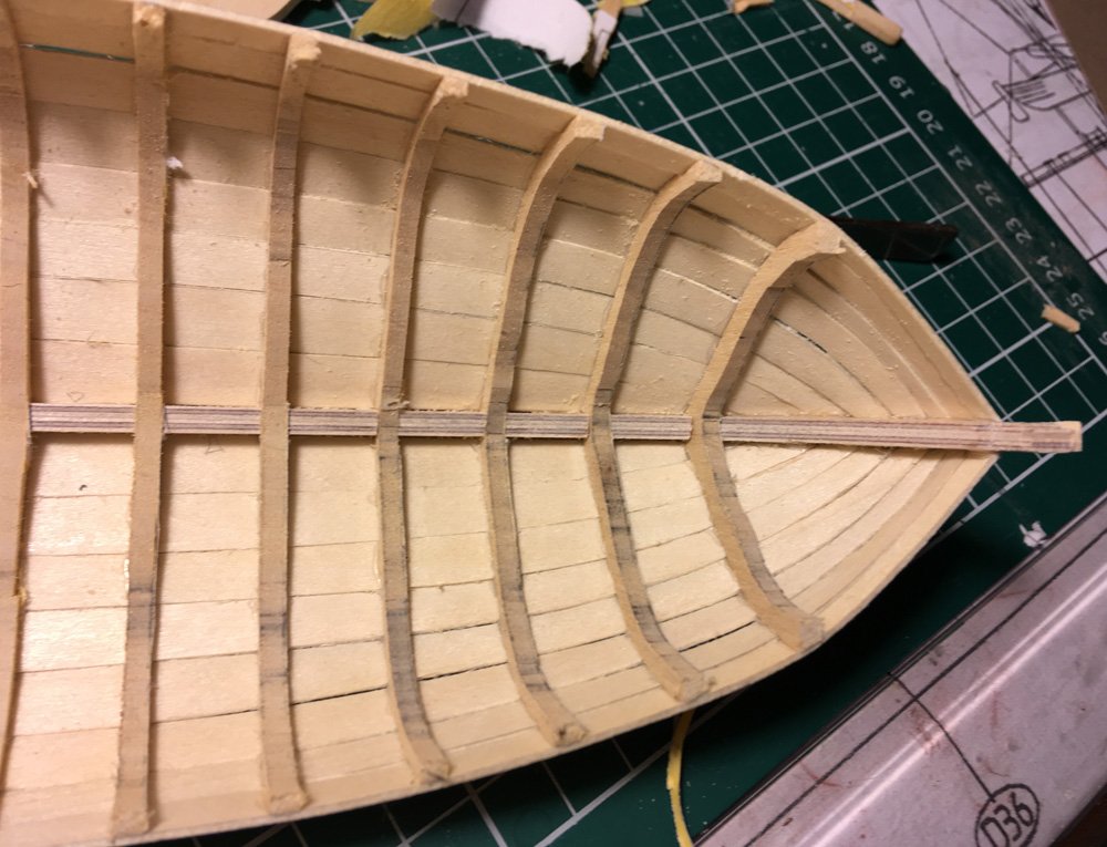
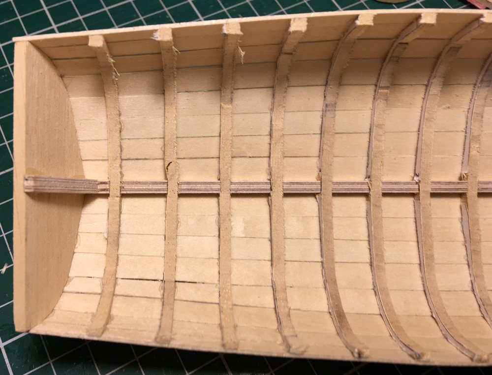
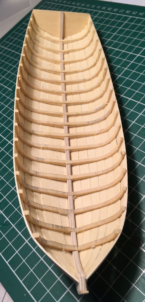
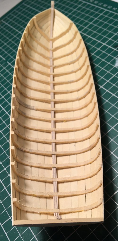
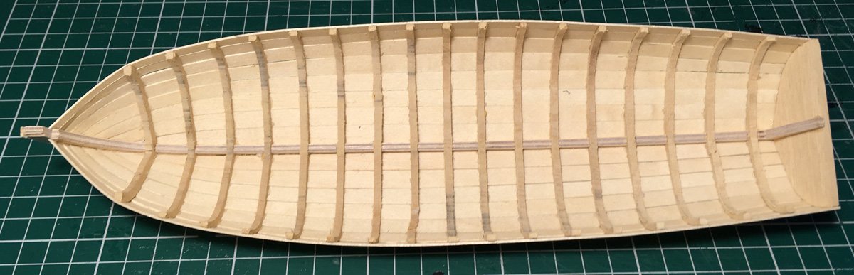
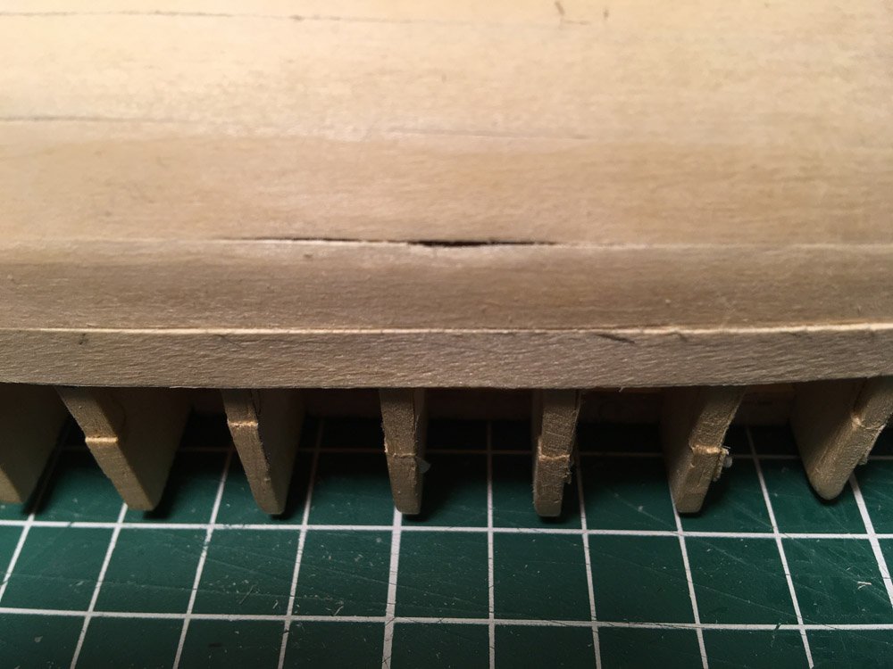
Well here we are, I finished the planking and let the glue set overnight. Then with great trepidation I cut the frames away from the jig. With some wriggling and gentle pushing the hull popped off. Now some detail shots External Inside from stern and stem close up I am really pleased with my very first plank on frame. It needs a fair bit of fettling, I have learned a lot by doing this The frames need a lot of sanding, but I have learned to be careful when sanding.... I think I can fix this by gluing in a patch on the inside so as a proof of concept it worked. Comments please. Tim
-
I don't have a lot of experience with model ships either, but along with the old hands on here, I welcome you. They are a great bunch. Tim
-
I will have to try this with tape, all of the tape I have at the moment is opaque. I have used some 90gsm tracing paper which sort of works. The problem with using paper is its a bit stiff and when transfering the shape to the wood, you have to cut the paper to shape then run a pencil round the edge, it's awkward and fiddly to get accurate. The tape method looks much simpler to do. I will look for some different masking tape, I tried parcel tape and sellotape, but could not get any marks, pencil or pen to stay on the tape. I see some people have used the special 'invisible' matte tape which I don't have. Tim
-
Wow, thanks Craig. I have only a couple of planks left to bodge on this build, ( the dirty boat ) but on the cedar version this is what I will do. I have copied and pasted it into a word document and will print it out so I can refer to it. Tim
-
Allan - thanks for reassurance Note to self : must pay more attention, not just zoom off following my nose. Tim

