MORE HANDBOOKS ARE ON THEIR WAY! We will let you know when they get here.
×


oakheart
-
Posts
518 -
Joined
-
Last visited
Content Type
Profiles
Forums
Gallery
Events
Everything posted by oakheart
-
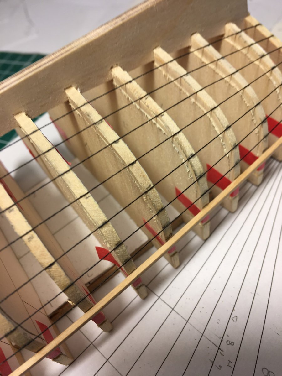
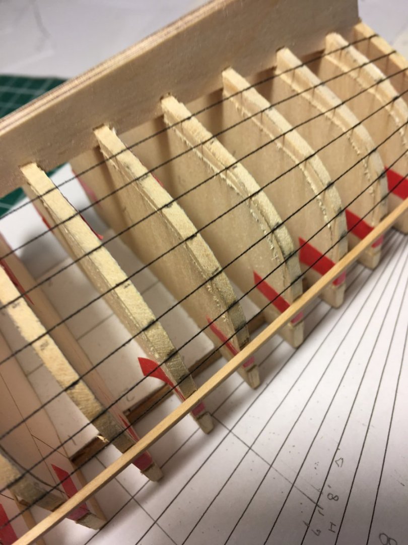
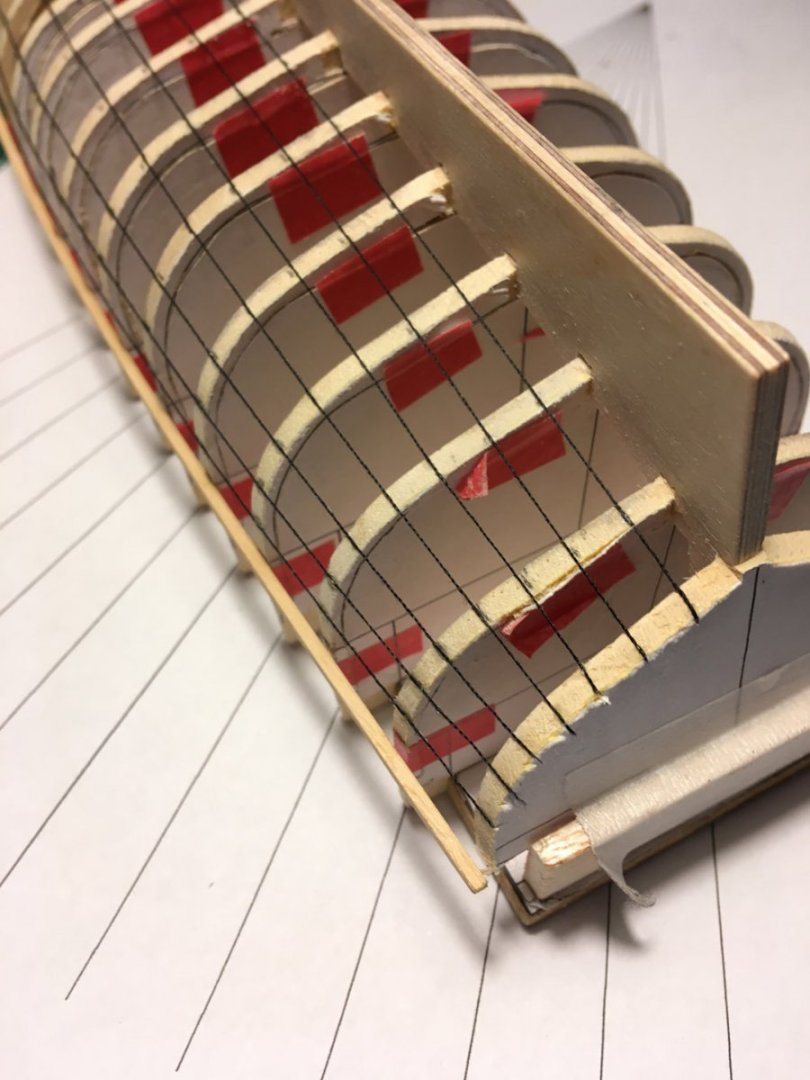
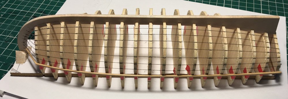
 Finally got this thing lined out, cotton seemed to work. Not sure about the stem end? This was really what I should have done before I tried to understand the planking, it really helps. Now to transfer this to templates. Most of it looks pretty straight foward, but I'm not sure how I measure and transfer the area between Station H and the stem the cotton is stretched in straight line but i need a curve how best to proceed here? Any advice would be welcome. Ignore the broken temporary square section, it had a nice curve then snapped, I should have soaked , live and learn Tim
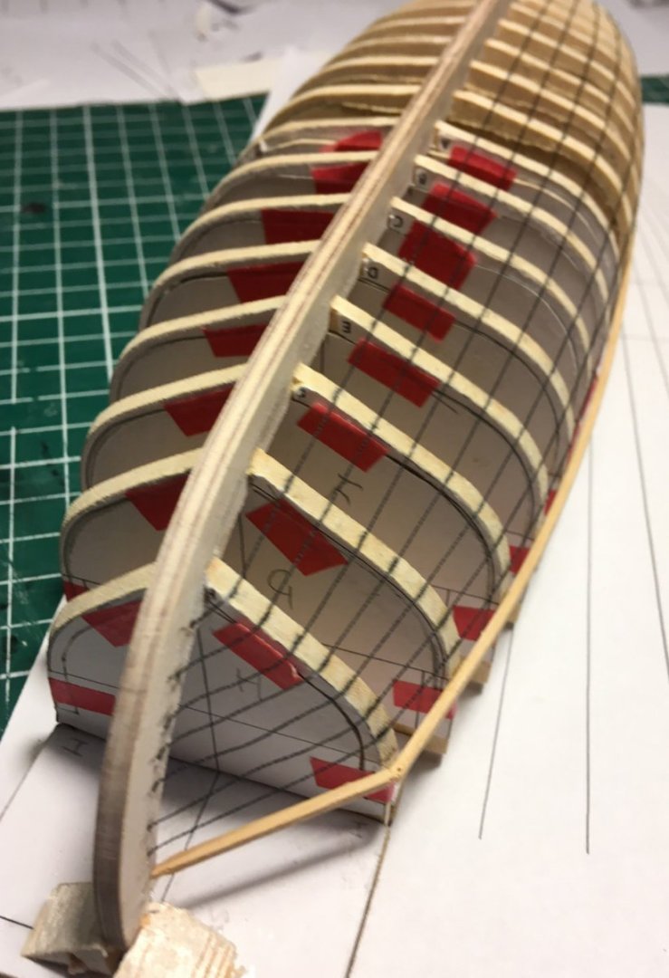
-
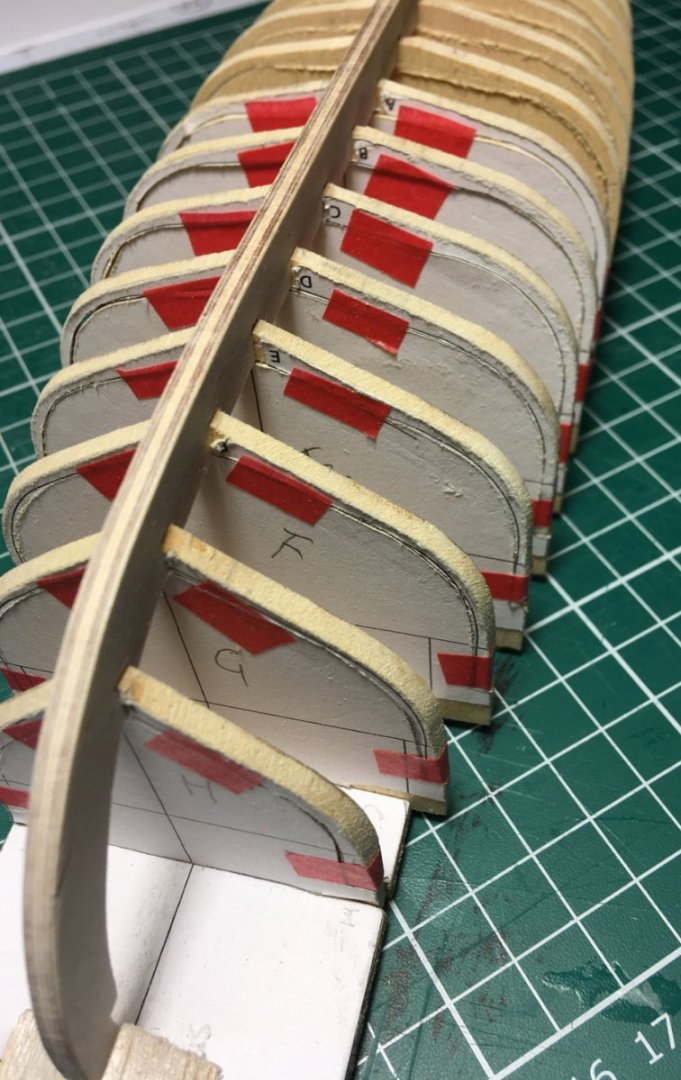
OK decision made at least for the first of the two builds, this will be the 'dirty' boat. No rabbet on this one, using the ply keel as it will be covered in tar/pitch as per Blights log. I am not happy with the way the futtocks cut out of the molds ( frames) the scroll saw seemed to have a mind of it's own today.... Still I should be able to clean up a bit when I have planked it. It's all glued up now so in the morning when the glue is hard, the transom needs fairing. Then I can line it out Not sure whether to use cotton or thin tape to do the lining having never done it before, maybe try each on different sides Then I can get on with cutting the planks ( spilling ) to fit Tim


-
That is looking really good. Can't wait to see the planking go on. Tim
-
Welcome Wizard, only a couple of weeks ago I was welcomed here as a newbie, I have found it a great place with lots of helpful knowledgeable people. Love you first build. Tim
-
Just drawn a custom planking fan, lets see if it works......... I still have not decided to go with or without a rabbet, there are good augments for both. Visually I am leaning towards no rabbet, as it will be easier to control the look of the join line. Tim
-
Now it begins to make some sense, thanks again Craig. I will spend this morning practicing my marking out based on your explanations. First to print out a planking fan and cut some extra tick strips. Tim
-
Having researched the subject, I am still having problems working out the planking on this boat. Am I conflating two or more different ways of approaching the problem. Chucks Passaro, David Antscherl and others. Here is what I understand so far : The planks are widest at station 0 and taper forward toward the stem and back to the stern ( transom ) So for each station I take a measurement of the frame from keel to gunwale in mm, divided by number of planks = plank width in mm at a scale of 1:24, I have the following dimensions on my tick strips in mm as a start stem : ?? station H : 40 / 8 = 5mm station 0 : 60 / 8 = 7.5mm station 8 : 44 / 8 = 5.5mm transom : ?? The widths at stations in between are then marked on tick strips by transferring dimensions from a planking fan. I still have not fully understood the use of the fan yet, more reading required here. When joining those dots what determines the amount of curve between stations? as a side note: I have a wonderful set of french curves that I got from the widow of a boat designer some 45 years ago. At last I can put them to their proper use. Tim
-
That makes sense, if it was a 'rubbed' joint it would be difficult to see the join. Tim
-
Don't know, I will do a test on my Version 1 frames and let you know. Most of the inside of the keel / strakes junction should be covered by the flooring planks ( forget the real name ). Tim
-
Hi Hakan Thank you, I will try to do a bit more fairing before I proceed. I will use a piece of wood and not card to give me a better idea Tim
-
Thanks for your input, but this is a different model, the planking does not go over the deadwood, this was discussed previously on ? Allans build ? Tim
-
Hmm, all I want is a good looking model, will it make a difference which way I go? I am tempted by the no rabbet idea. Most of the time the model will be viewed from above and the join between the keel and the plank will not show as a dark shadow. If I cut a rabbet the join will show as a shadow line. As long as I can get a good bevel on the planks, I think the no rabbet would look better When I made models to be photographed all I wanted to achieve was something that looked good to the camera lens, what the eye did not see was not important. Tim
-
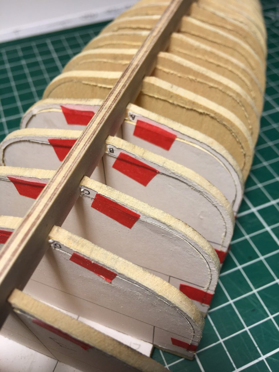
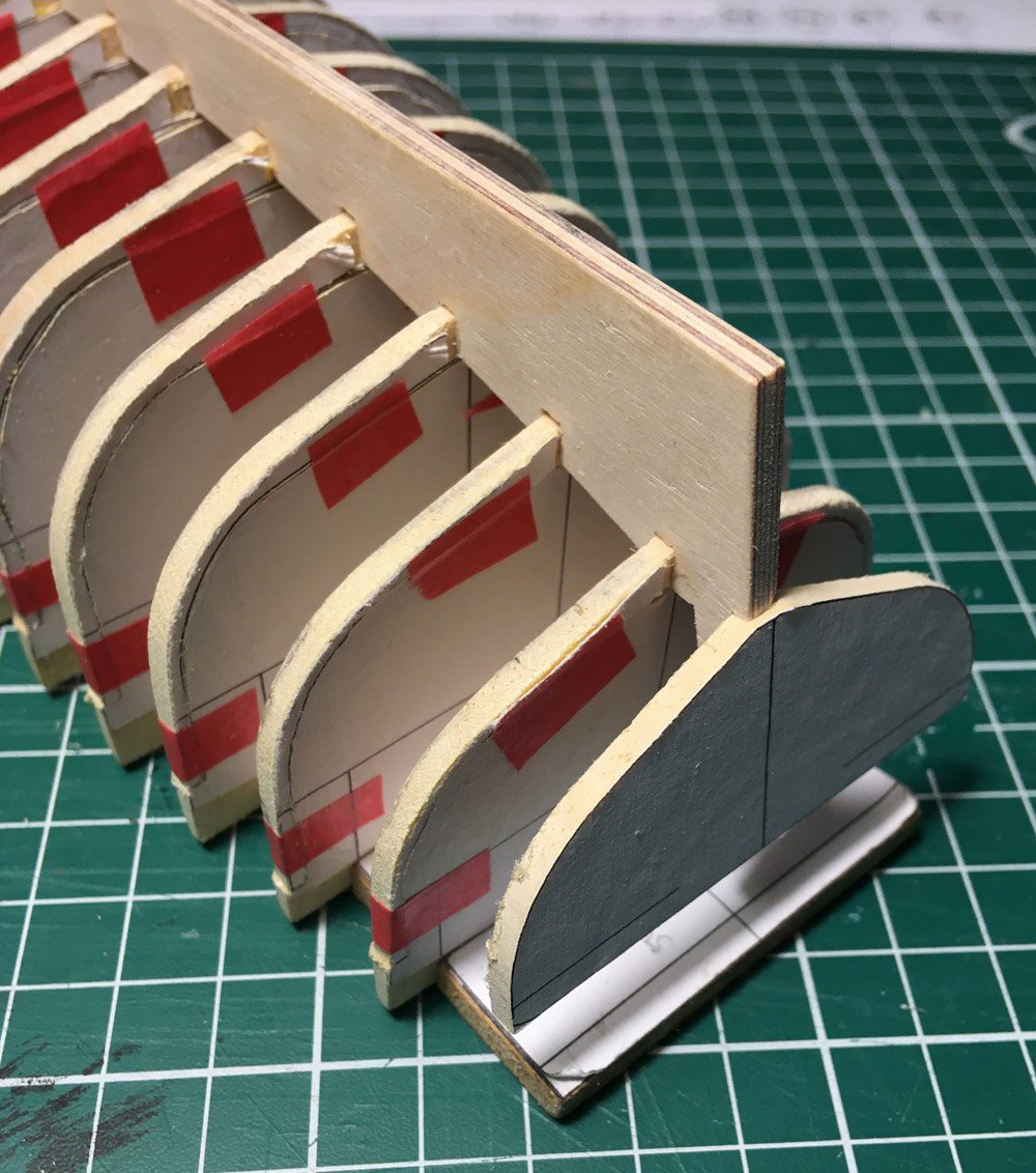
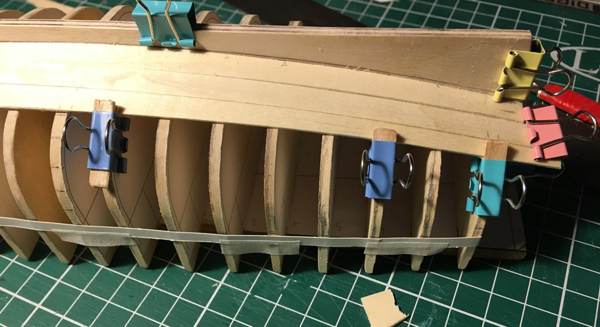
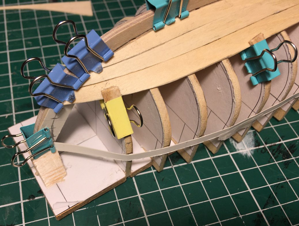
Here is a couple of photos of the planking templates I've been working on. They are not glued in place, just held by the clamps, lots of adjustments to make before I commit to the good wood. Also I have not cut the rabbet yet. I have read on this site about not needing to do that? Comments please................. This is fiddly, I don't think I could do this at 1:48 like Allan is building I would become a nervous wreck.
-
I love all of those ideas, just need to get the hull complete, then try some of them out Tim
-
looking at all of the variations in post 21, on my build I think I will opt for, counting left to right No. 7, it's simplest to make ( typical of me ) also on all of the contemporary artist drawings / paintings I don't remember any showing a rubbing strip? anyone else see anything? Tim
-
The frames are now pretty fair. So working on my planking,. I have made some progress using cardboard templates then transferring the shape to basswood sheet. I am finding it easier to cut and sand the basswood to fit than cut / trim the card. So I may just waste some of my basswood sheet to make set of masters. Then cut the hero parts from those. I am now even more in awe of how the kit makers like Chuck Passaro and Chris Watton manage to design and produce their kits. Hats off to you guys. Tim
-
Thanks for the links, I have read the articles on this site along with others, the book seems to cover a clinker built hull, which although of interest may not help with this launch which is carvel planked. There are some amazing videos of full size planking builds on YouTube. Again interesting but difficult to translate to model making. Tim
-
While fairing the frames today I was thinking about what Bligh and the crew may have done to make the canvas screen round the edge of the boat... As Purcell the ship's carpenter had his saws he could have sawn up bits of the boat to make parts for the screen. Did the just use a low strip all the way around, sort of like a canvas washboard or did they use big sheets of canvas fixed at the gunwale then up to the rigging to keep the worst of the constant splash from the big waves. Did they catch rainwater in canvas sheets . Use four oars fixed upright in a square with canvas across the top, hole in the middle with a bucket in under the hole. now the mind races away, how will I model this ? nobody knows what they did so I can make up anything that I think might have worked, could be fun. Does anyone have any other ideas? Okay back to the sandpapering now. Tim
-
That's some really good interpretation work there. I can hardly understand the language from the book. Your drawings, brilliant as usual, are really useful to those of us at the planking stage like you. Thank you for sharing them. Ti m
-
You can probably tell, for this scratch build I have been heavily influenced by Chucks longboat kit design ( Thanks Chuck ), the jig base and other elements are a direct copy. This is not a pirate copy honest! Tim
-
Hi Gregory, thanks for dropping in, I was just going through your build this morning, very nice. I have picked a load of good details already, thank you for sharing your build with us newbies. I will down load those docs and read through them. I am really having fun working out how to progress with this build. With all the help I am getting it may even get finished. Tim
-
After reading loads of the planking tutorials on here and watching chucks videos etc. etc.. I still have questions. For the Garboard Strake ( the plank next to the keel ), 1: How do I work out the curve for the stem end? 2: How do I work out how far forward should it be? Here is the one that Craig did for his 16ft cutter, even scaled the curve in not right for my 1:24 23ft launch I could just use the cardboard template I have made and keep hacking at it until I get something that fits, but is there a better way? Tim

-
I also do a lot of work on brass using a jewelers piercing saw and the rules are similar with regards to teeth number and stock thickness, every blade manufacturer has a chart. When cutting wood for model boat making on my old Delta scroll saw I use a medium tooth count piercing saw blade ( will have to check count ) it's very fine compared to the chunky blades normally supplied for scroll saw use. I tend to use the No. 4 size with 15 tooth count I have gone finer but for wood these are good. If I can keep it straight, It will cut down the centre of a 0.3 mm line. The blades are good for hardwood, plywood upto about 12mm thick. Not so good for ripping along the grain. see https://www.cooksongold.com/blog/buying-guide/a-jewellers-guide-to-saw-blades/ for chart of sizes Tim
-
Thanks for the compliment. I have used measurements directly off the ZAZ7361 drawings ( ha ha against ingrained brainwashing ), would they be different from those on your scantlings list. The futtocks are 2.4mm square to be correct they should be 2.1and tapered, but they became too flimsy so I beefed them up. If I used 2mm plywood it might work, or I could try the bent square section like you did. I will stick with this as my first build and see how it works out. Your description of the gunwale on your build log really help me to understand how the top of the planks should go together. Tomorrow I will make some tick strips and cut some 1 mm cardboard planks to start setting out my planking Tim
-
Thanks for the encouragement. I like the chalk idea, it's a shame I don't have any laser char to guide me 🤐 Tim