Paul Salomone
-
Posts
188 -
Joined
-
Last visited
Content Type
Profiles
Forums
Gallery
Events
Everything posted by Paul Salomone
-
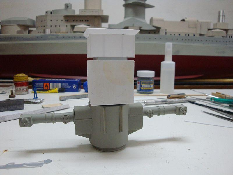
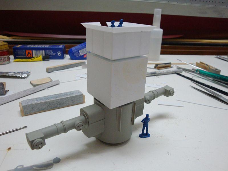
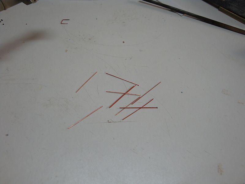
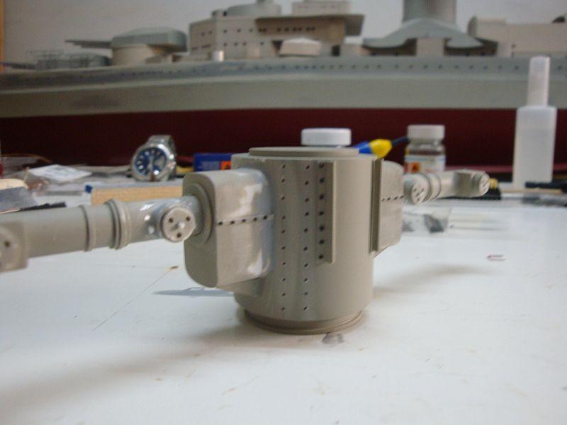
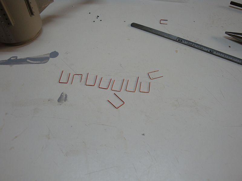
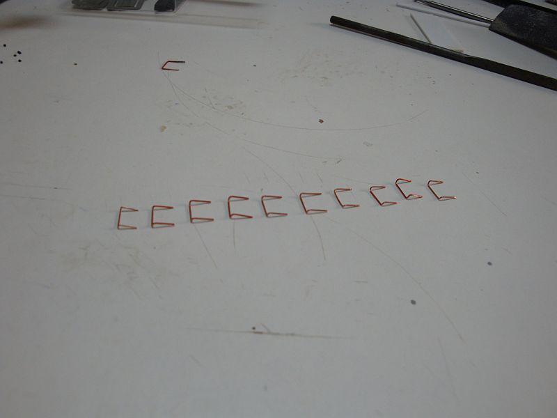
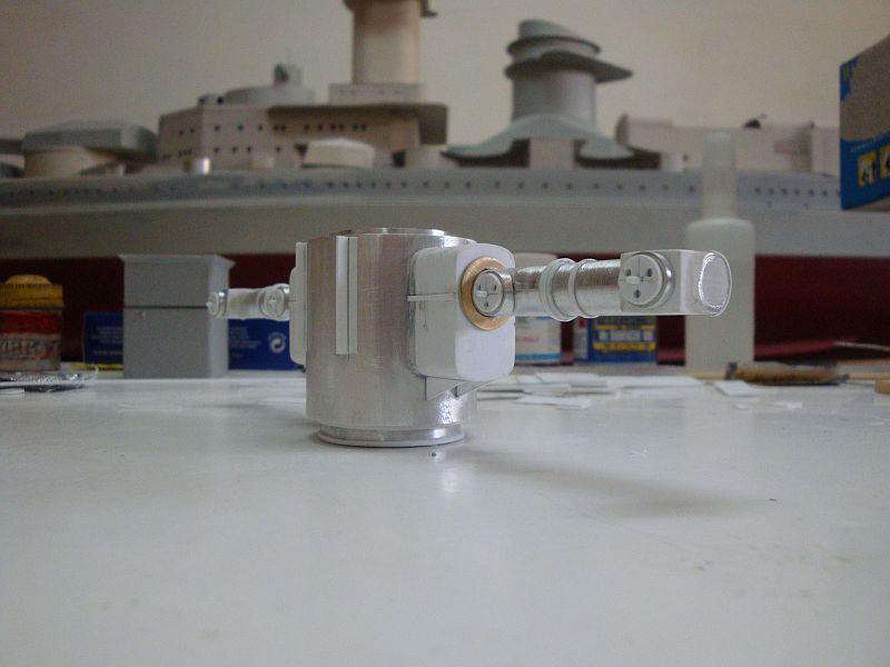
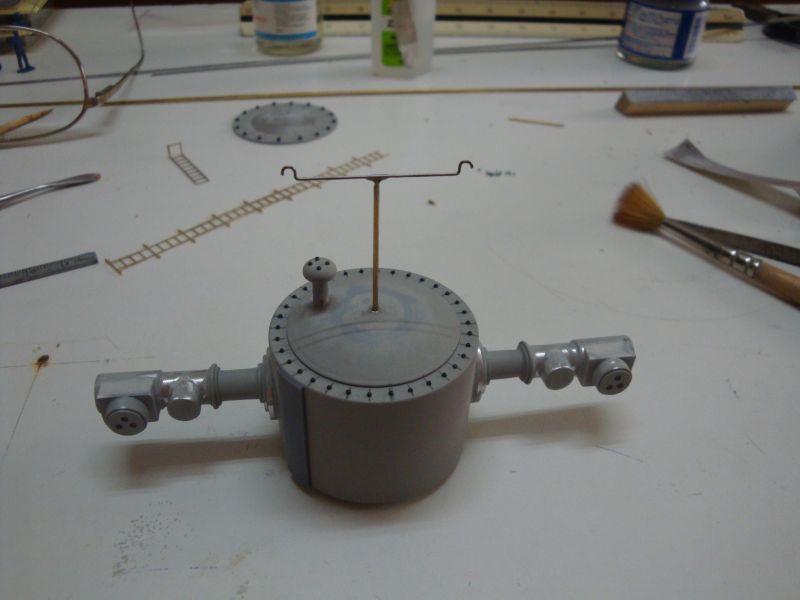
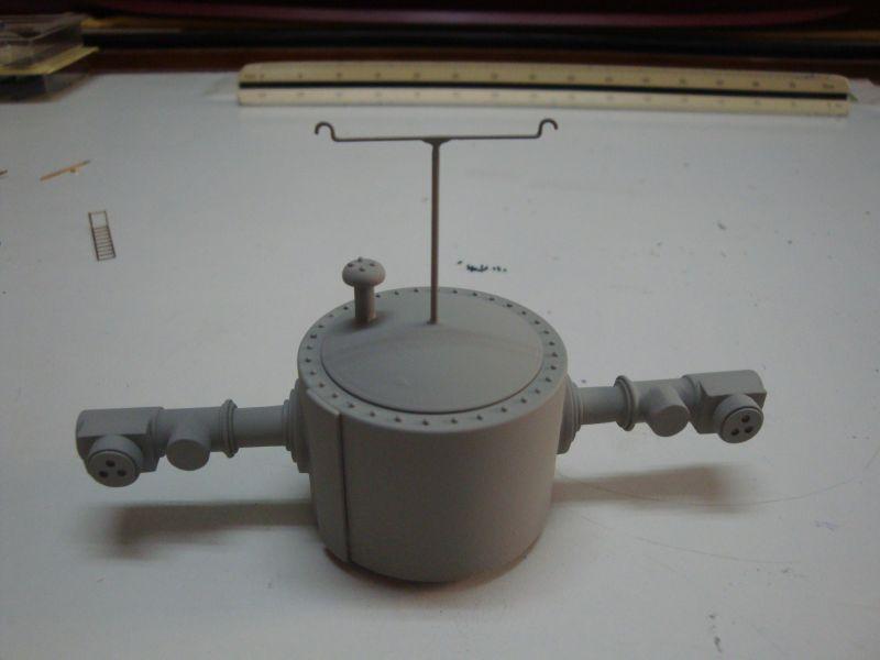
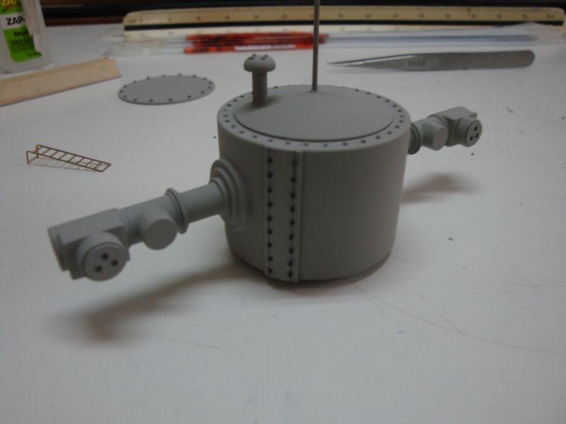
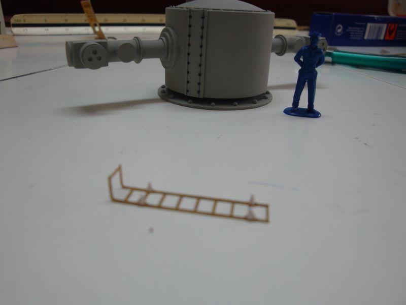
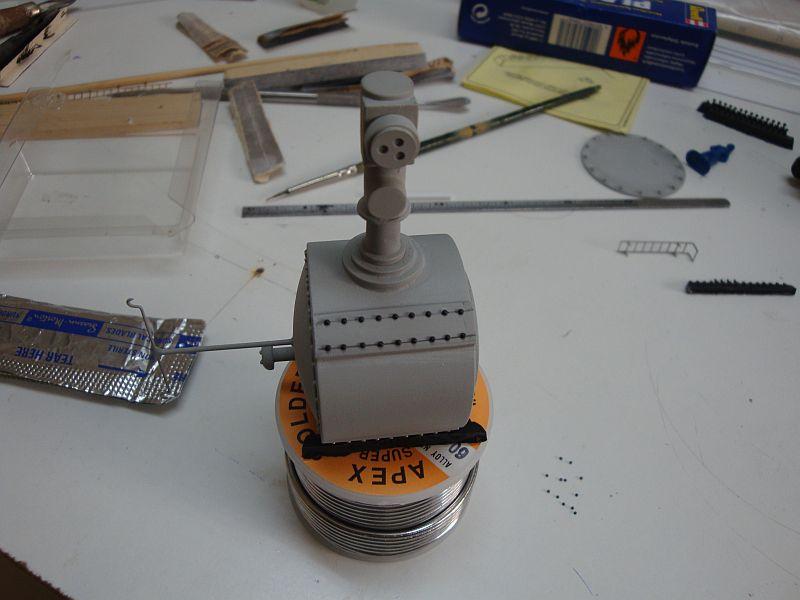
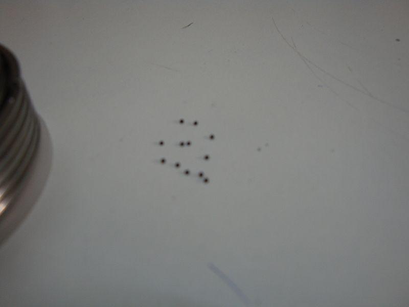
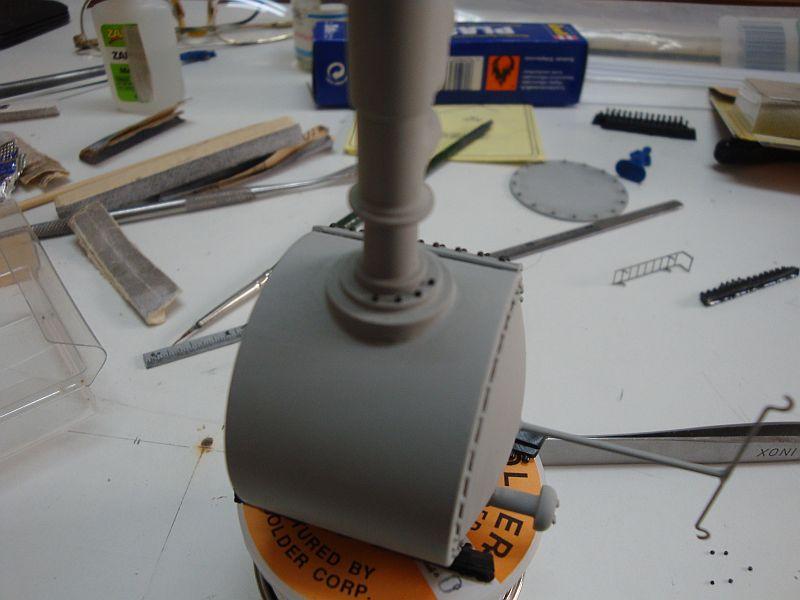
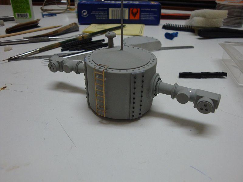
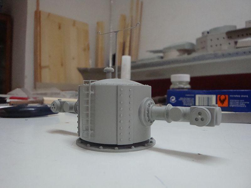
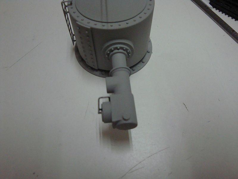
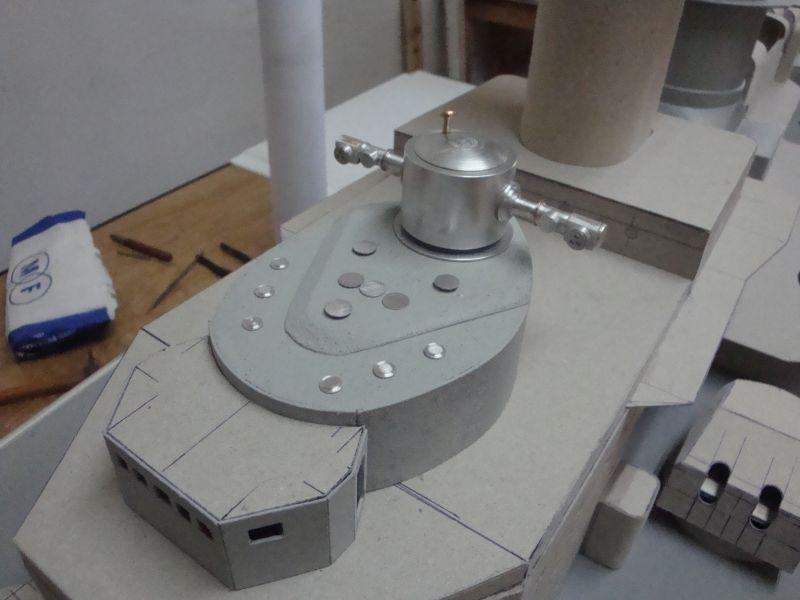
 Good morning all, Hello Pat, Thanks for looking in and for the encouraging comments. Today, I am posting the second part related to the construction of the main range finder/radar station. Here goes. The open top observation post and the equivalent closed type, situated underneath. A closer look. The range finder with it's first coat of primer. The observation post sited on top of the range finder. Some figures placed in the observation post, for comparison of scale. Copper wire to form the ladder steps. The range finder displaying the connection ports for the ladder steps. The holes were drilled with a 0.5mm bit. The ladder steps taking form. The ladder steps, ready for installation. A view of the rangefinder with the ladder steps in place. A viewing porthole added to the closed observation post and the FuMB 4 SAMOS Radar in place. A side view. Shall be posting more next week. Tomorrow is General election day here in Malta. I will certainly not waste my good time to vote, but will invest my time to work on the admiral's bridge. Monday is a holiday as well, as the winning party shall be celebrating throughout the weekend and Monday. Wopee - that means three days of scale modelling for me. See you all next Tuesday.
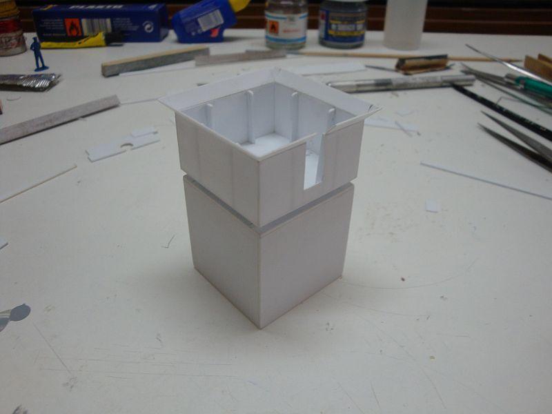
-
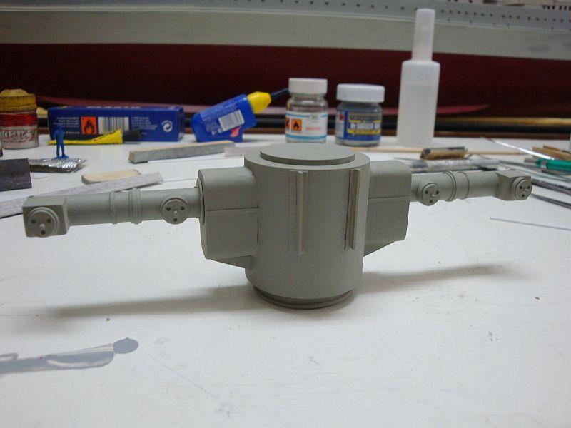
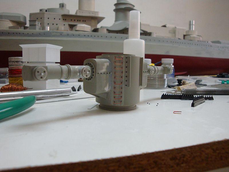
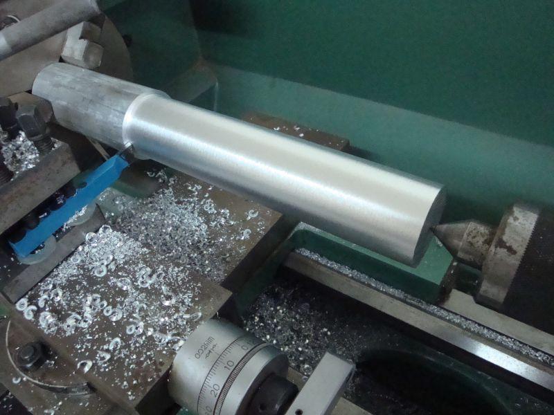
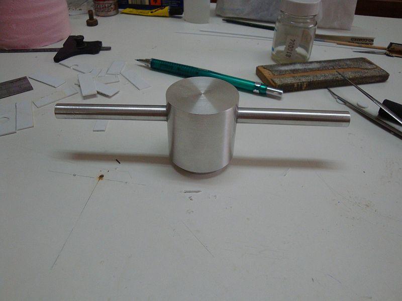
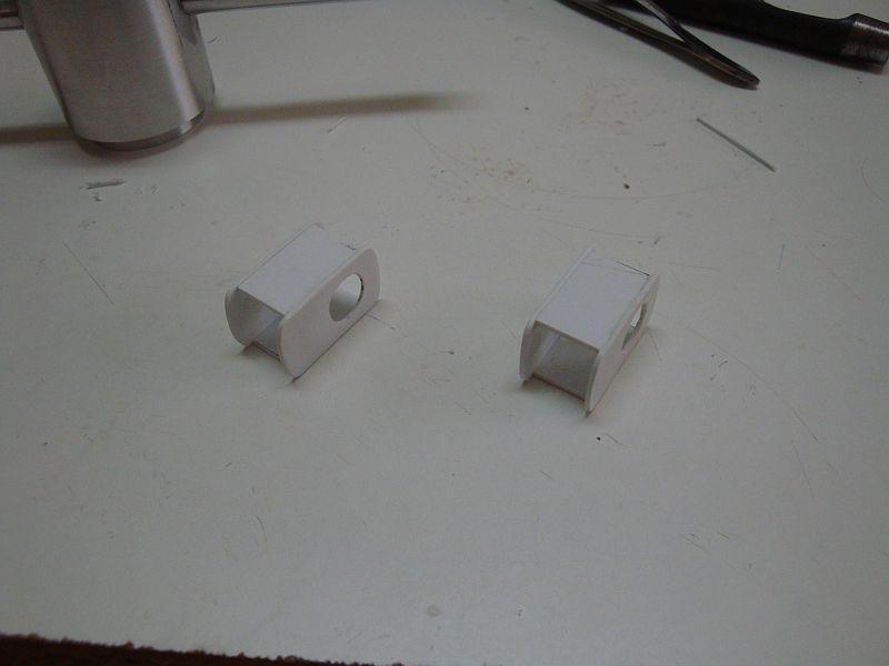
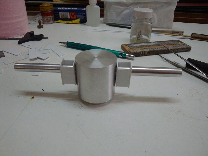
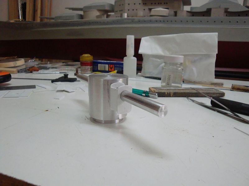
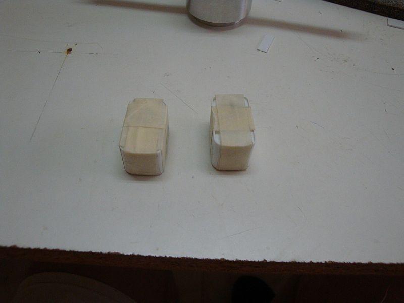
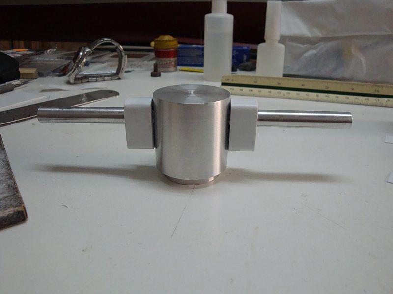
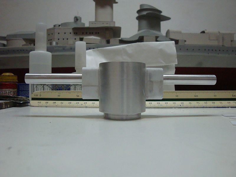
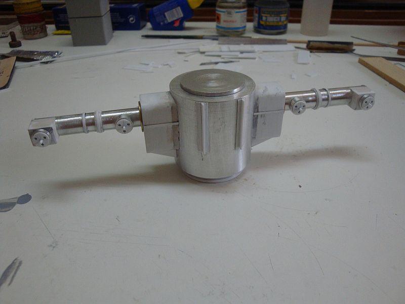
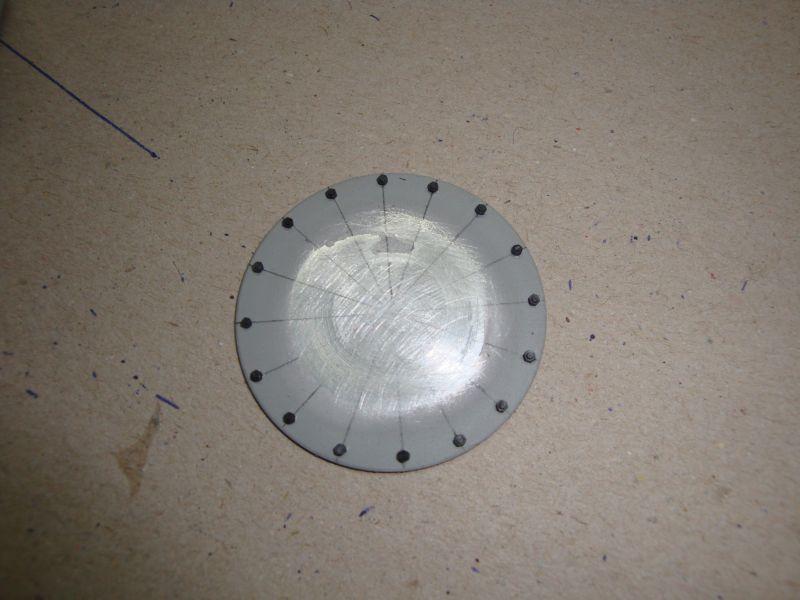
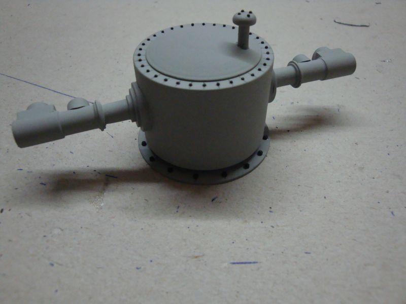
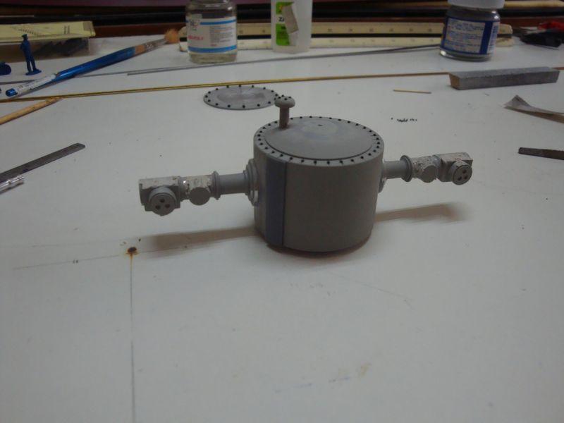
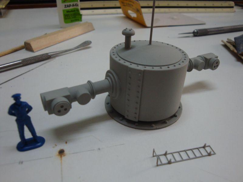
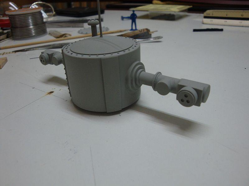
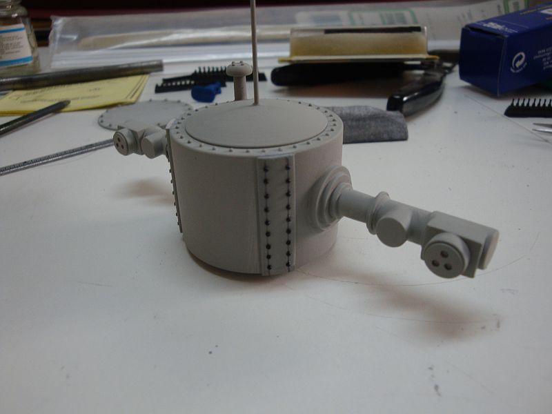
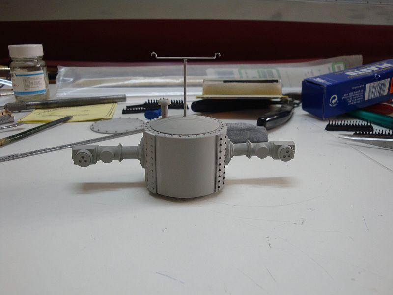
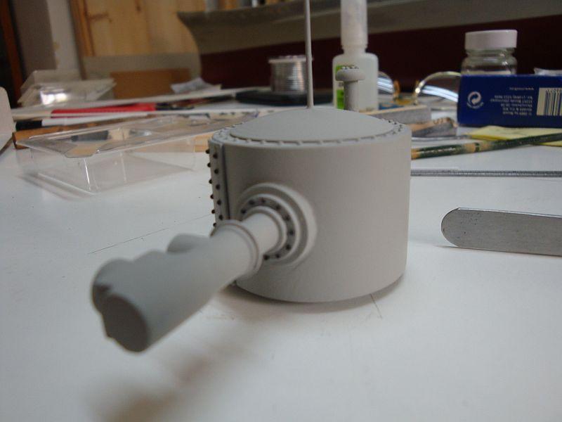
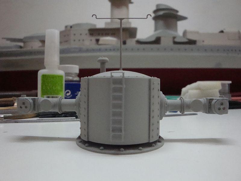
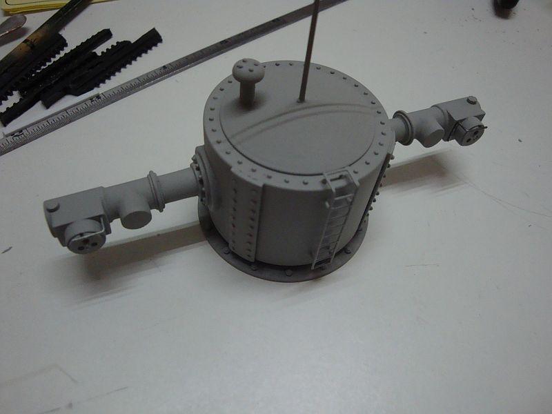
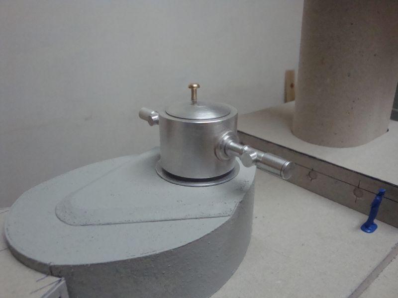
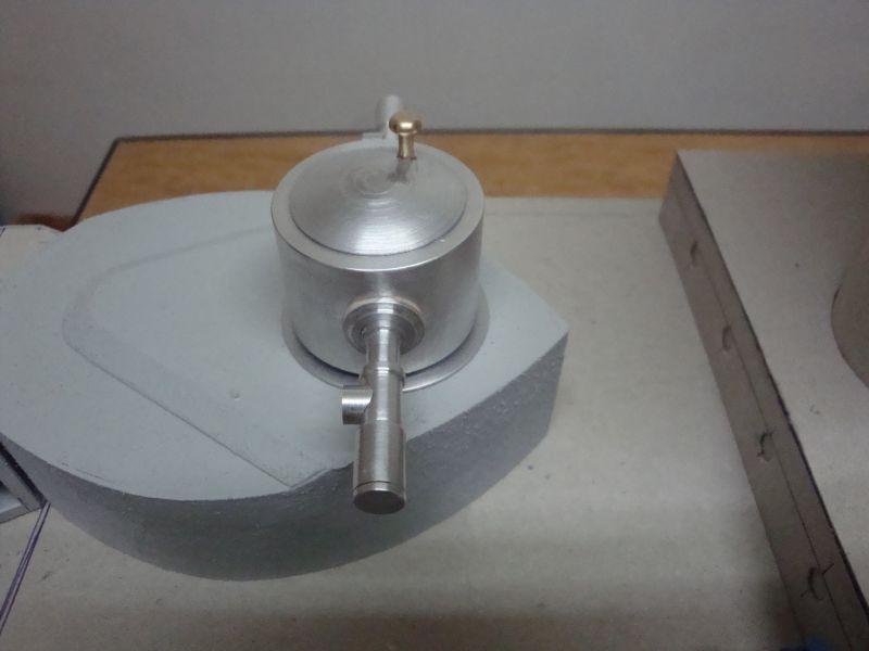
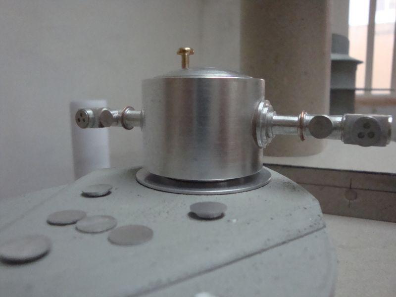
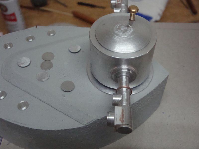
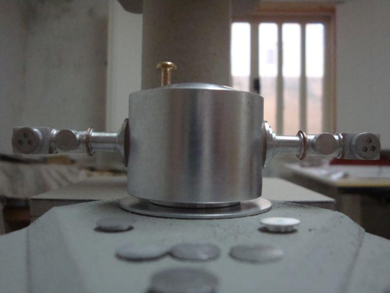
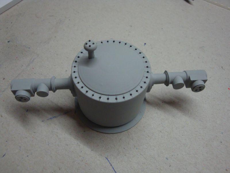
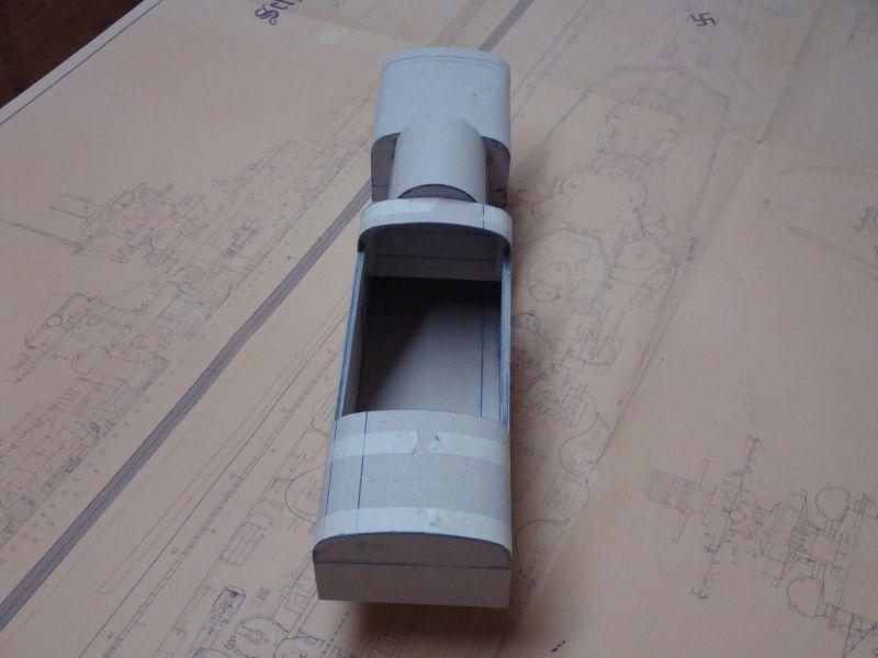
Good morning all, As advised, today, I am posting the pictures related to the construction of the main range finder/radar installation. Here goes: The start of the assembly - the main housing turned on the lathe. The two binding components - the range finder housings and the range finder sleeve housing. The structure of the two side housings made from styrene sheet. Checking for correctness. Another view. The side housings, under the tension of the masking tape. The side housings in place. Filling the gaps with filler. Adding on the final details - the lens housings and the connection flanges. A bottom view. A close view. Shall try to post part two today.

-
Hello Larry, Hello Greg, Good to see you back, can't wait to see your posts again. Greg - I fill the seams with thick filler paint, applied with paintbrush.
-
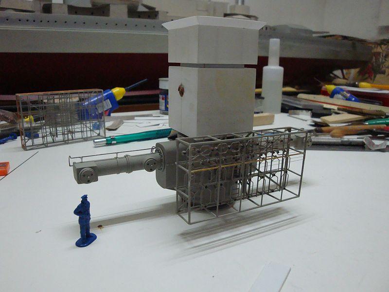
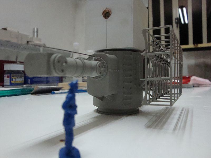
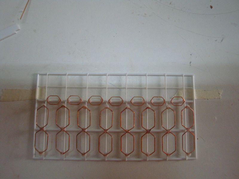
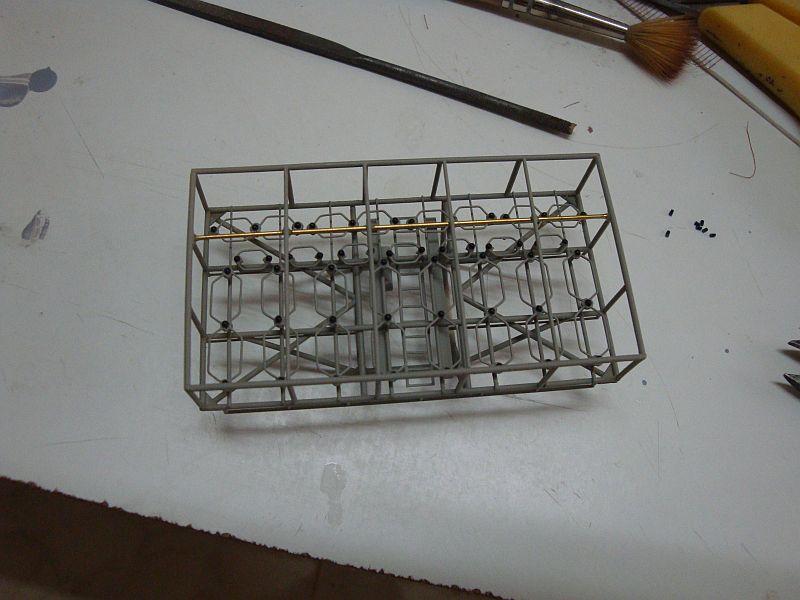
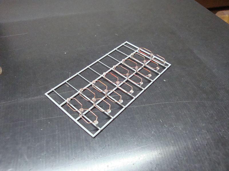
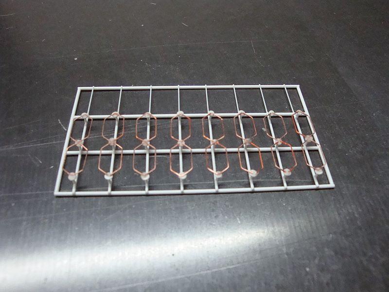
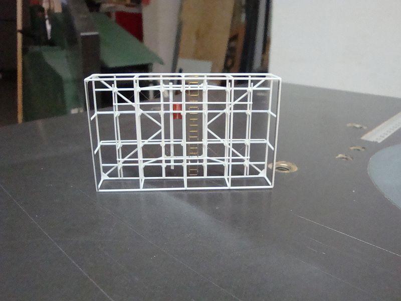
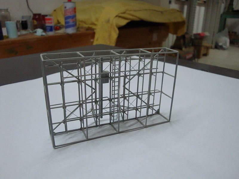
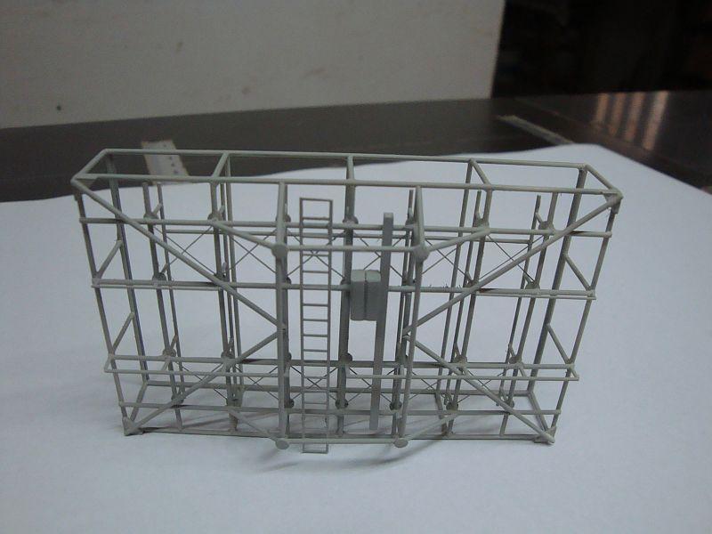
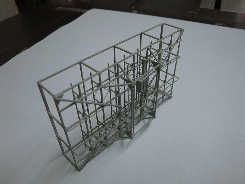
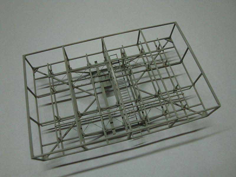
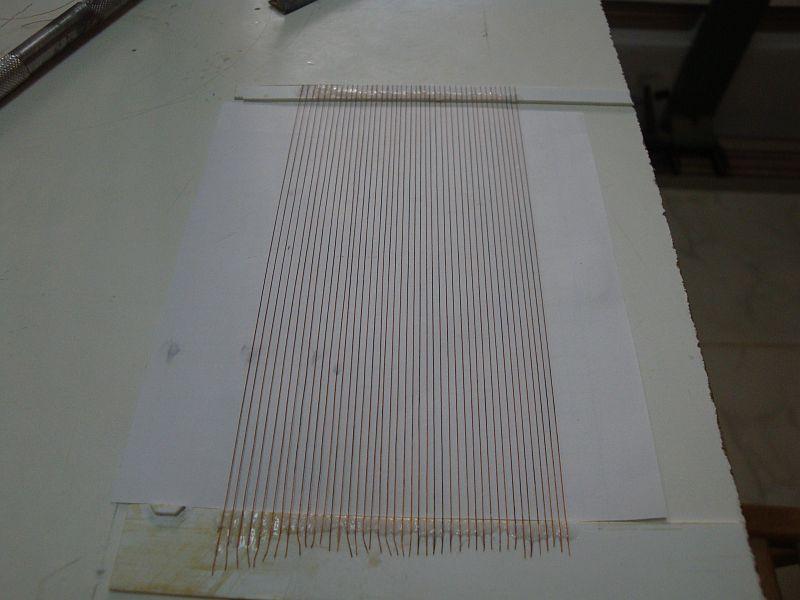
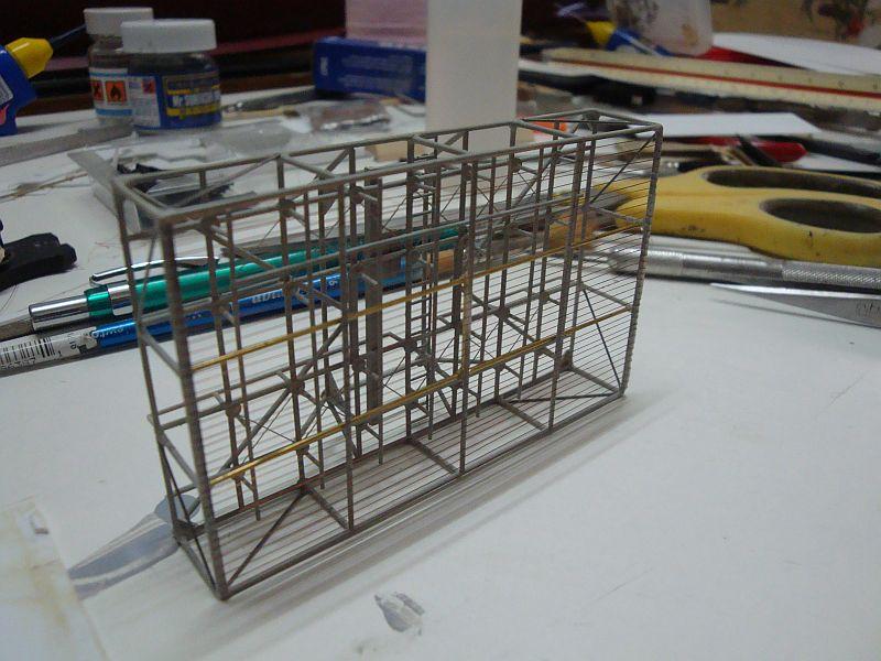
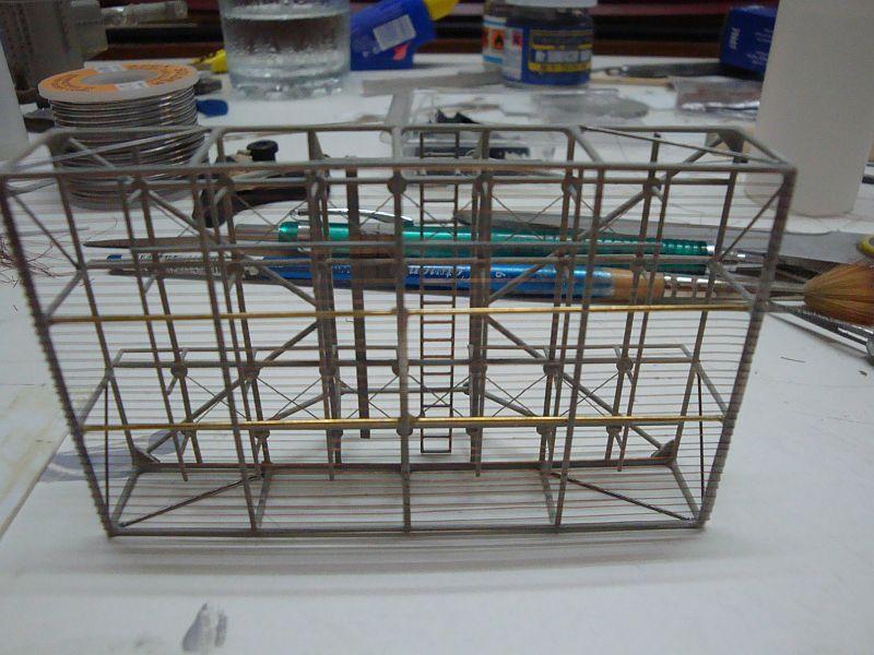
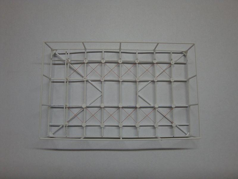
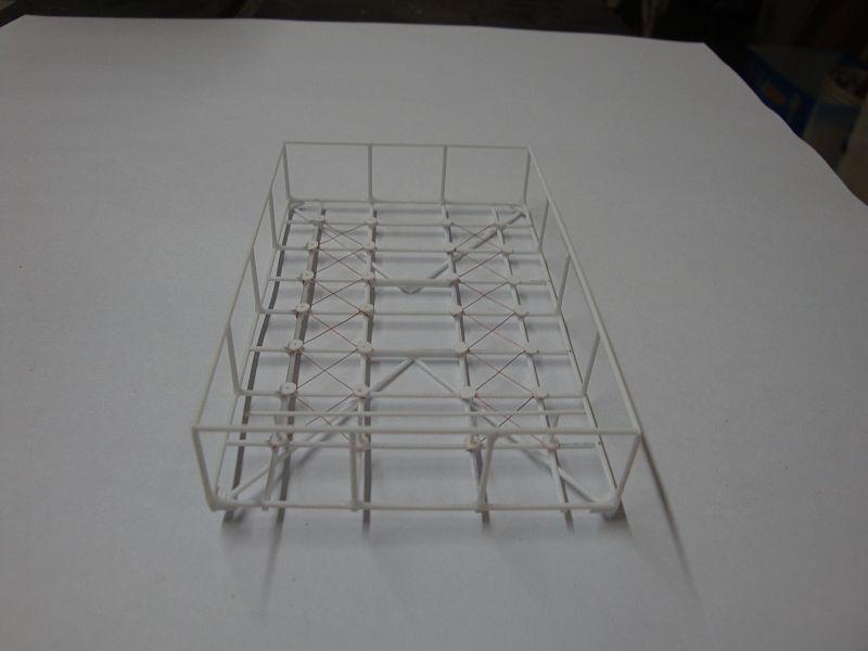
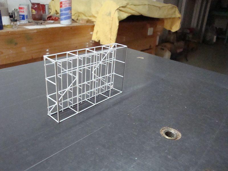
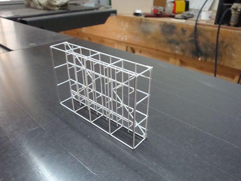
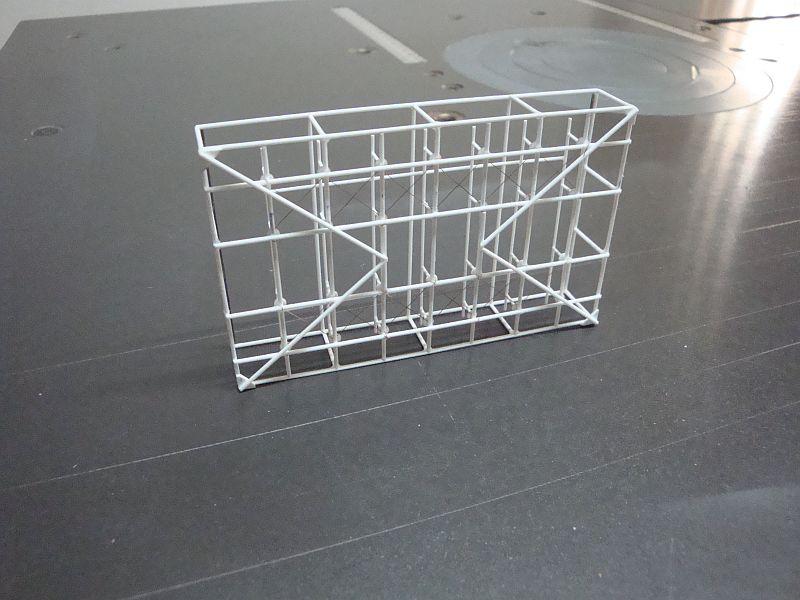
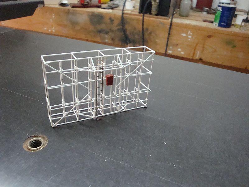
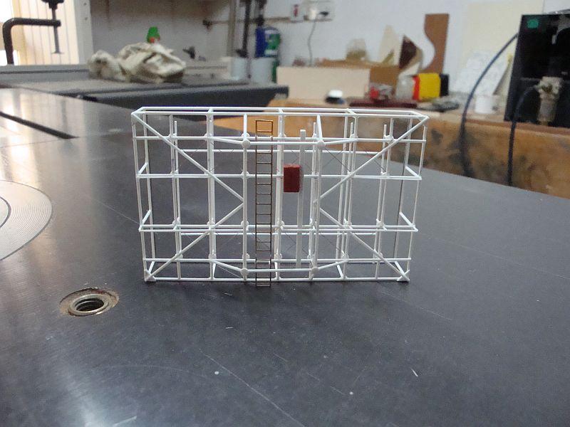
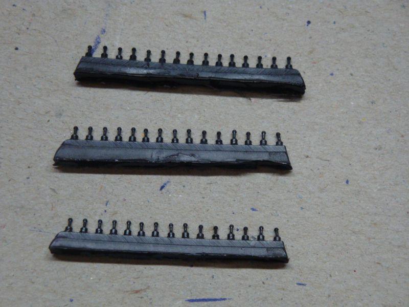
Hello all, The second part related to the construction of the FuMB 4 SAMOS Radar. Here goes. Work is progressing well. The full set of di-poles required for the job. The second set of di-poles in place. The third set of di-poles, displaying the mounting feet. The base radar, with it's arms to support the protective mesh cage. The third set of di-poles in place. A close view. The radar, with it's protective cage. The support structure of the radar. The radar, in it's final stages, prior to the final assembly in place. Tomorrow, I will start posting the final assembly of the radar installation. There are some 112 pictures, so I shall be posting 10 pictures at a time.
-
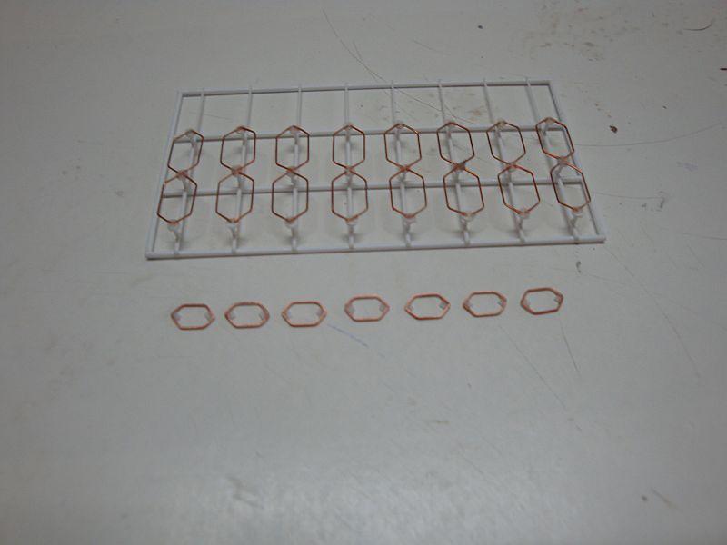
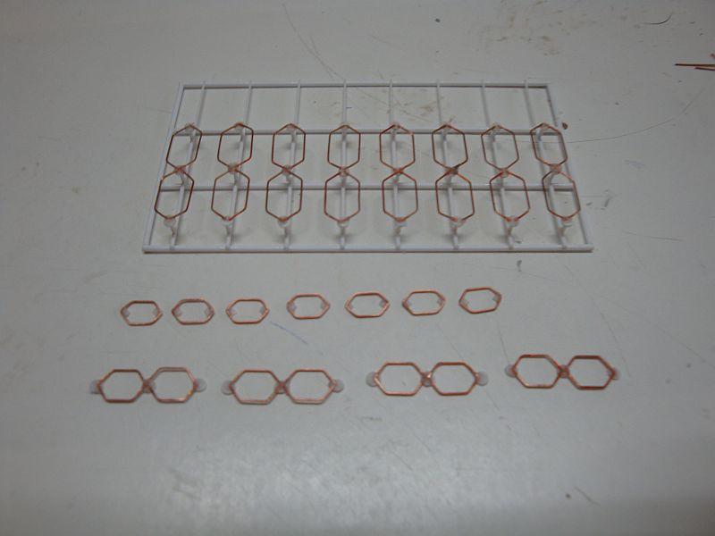
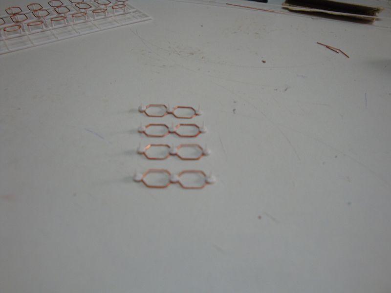
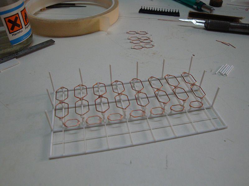
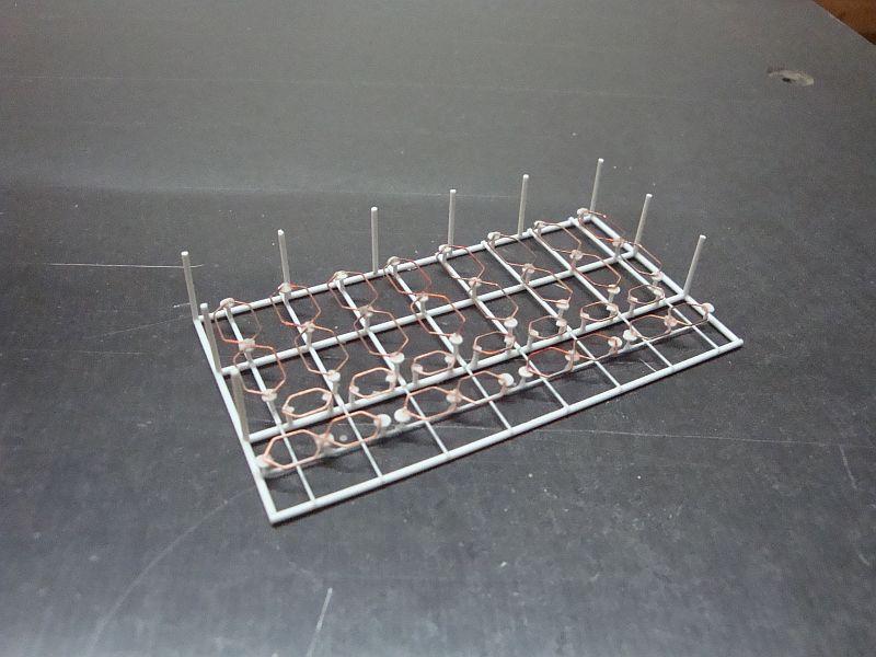
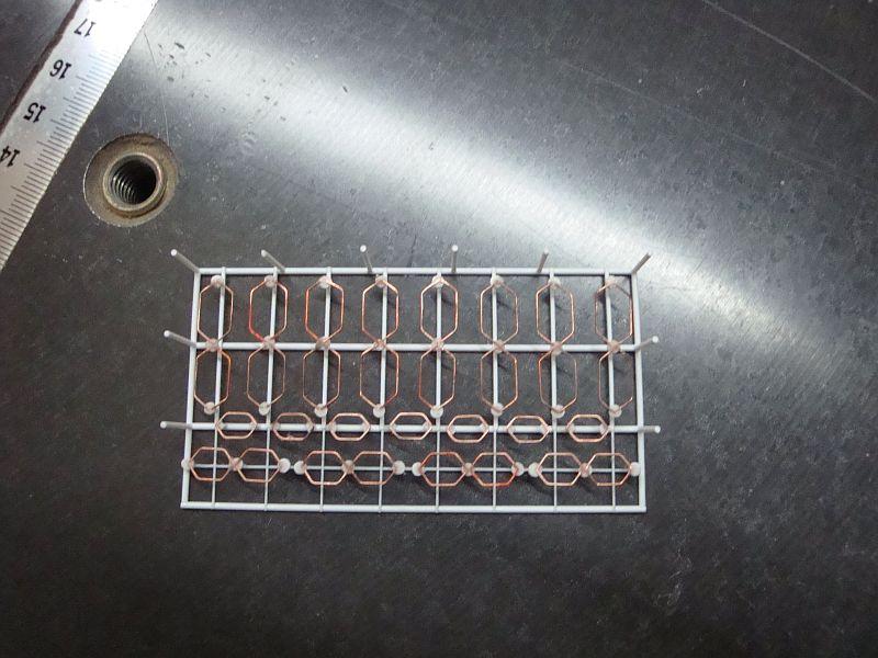
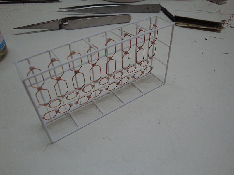
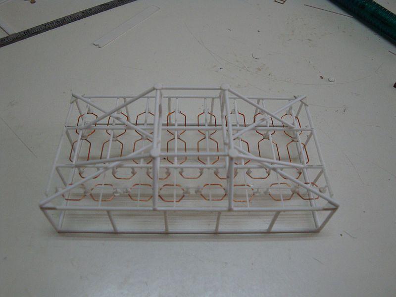
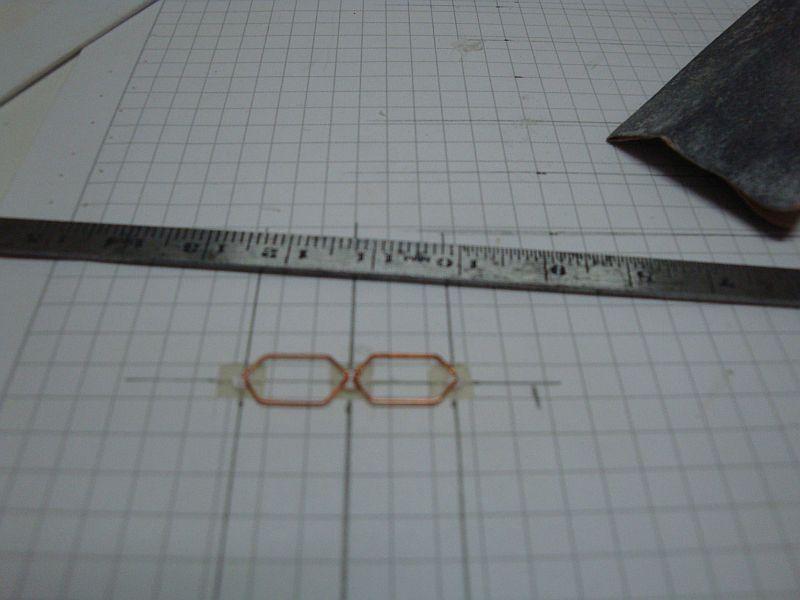
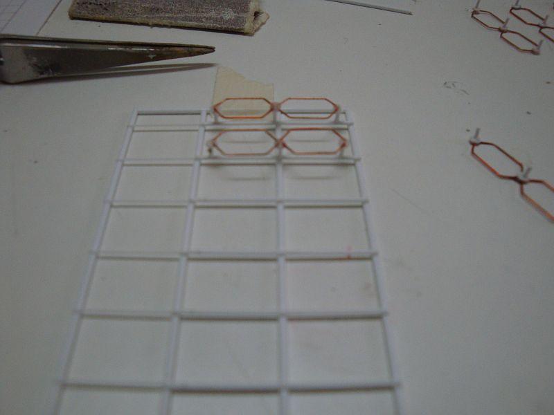
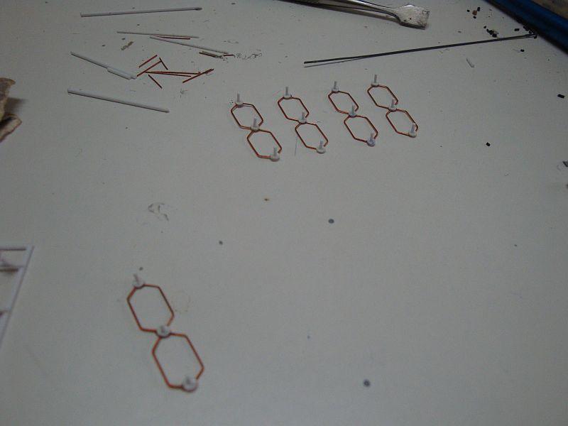
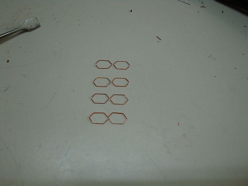
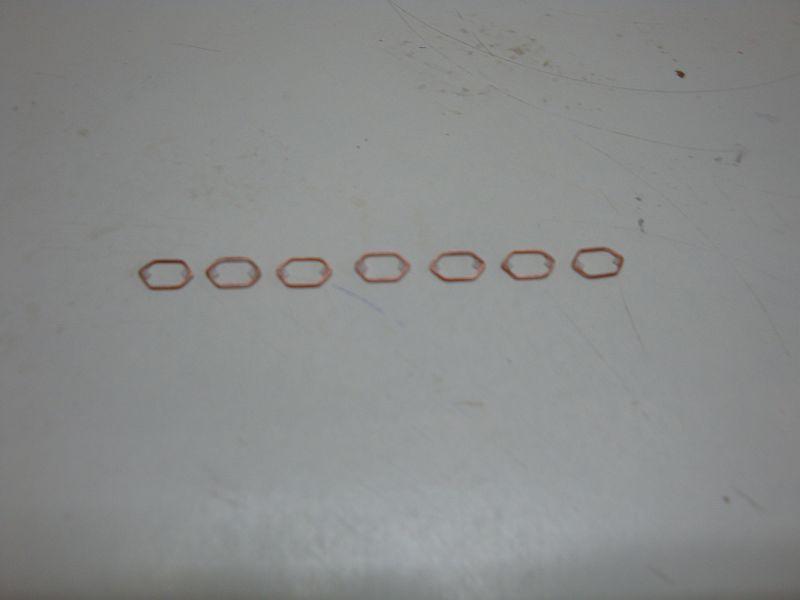
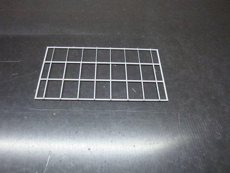
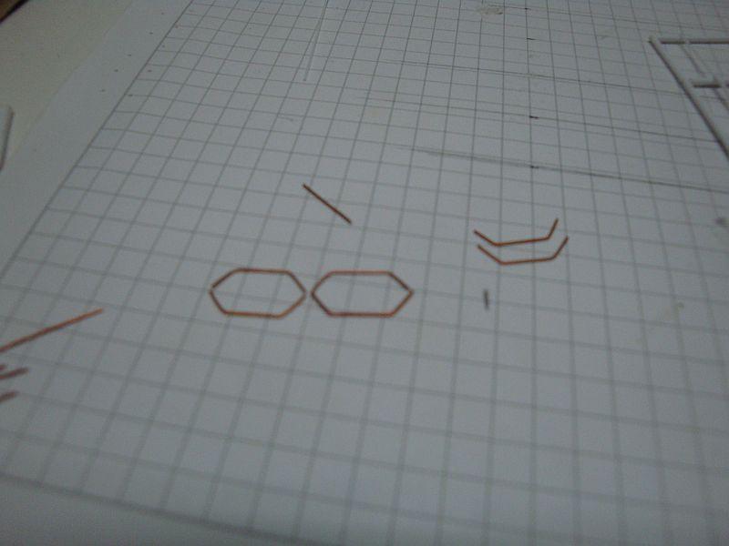
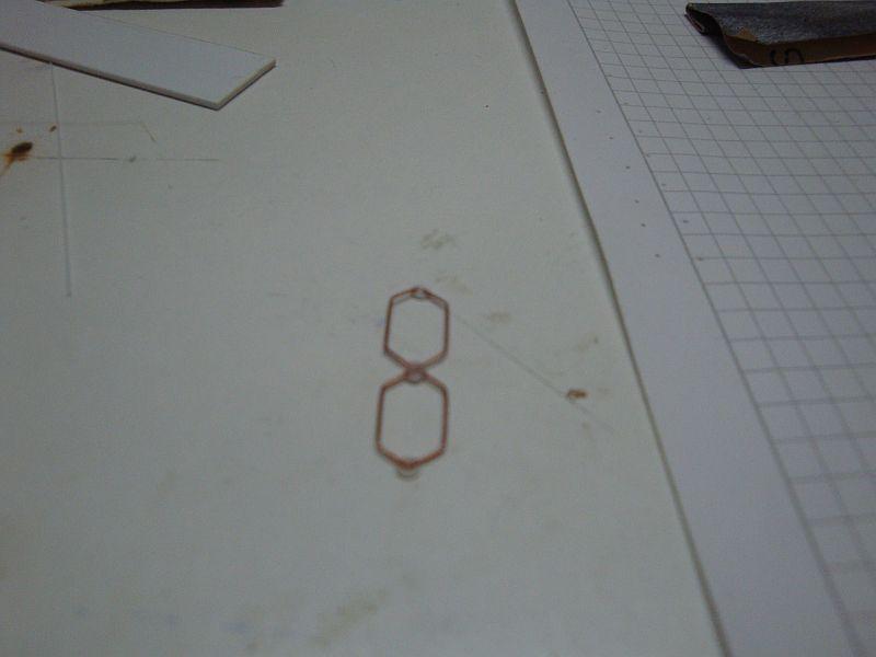
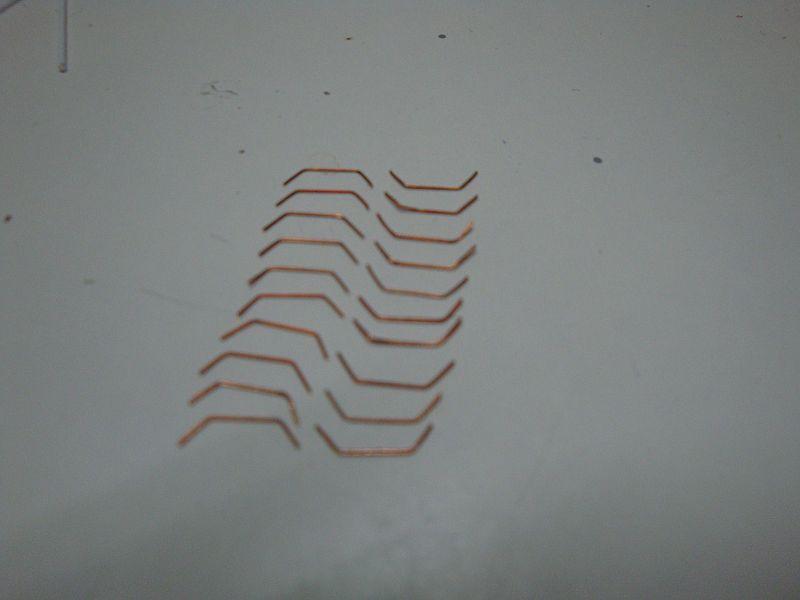
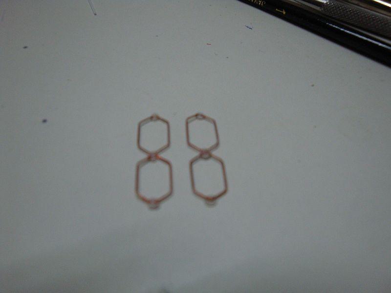
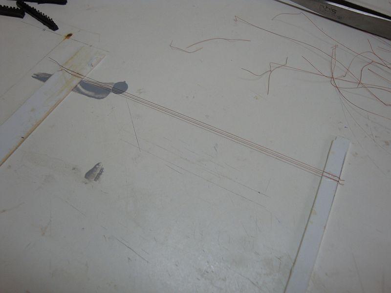
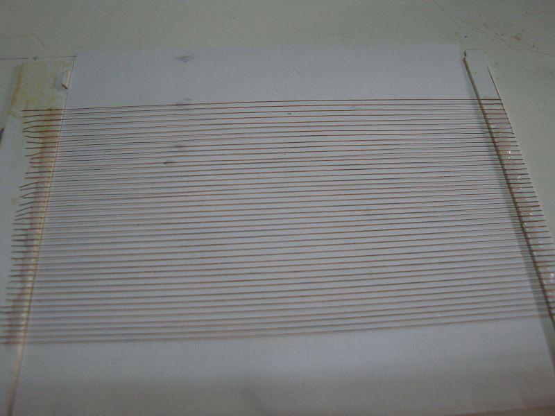
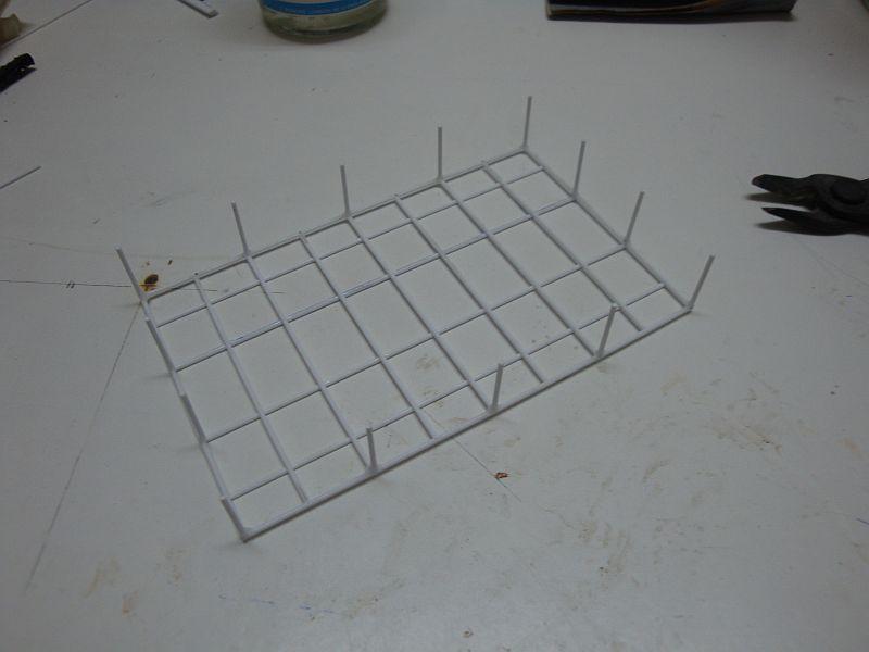
Good morning all, Hello Ben and peter, Thanks for the encouragement. I really need it. At the moment I am finalising the detailing of the inside of the wheelhouse/admiral's bridge, and is making me go crazy, but at the end, it will be worth it. Today, I am posting the first part of the construction pictures related with the assembly of the FuMB 4 SAMOS radar. Here goes. The main base frame, made from styrene rods. Forming the Octagonal di-pole, using copper wire. The first di-pole ready to be assembled in place. each di-pole is made out of 13 pieces. The full set of pieces required. The first two di-poles ready for the next step. The third, is being assembled. The first two di-poles, are placed on the base frame. The rest of the set ready to go in place. The di-poles assembly. A closer view. The next set of di-poles, under way. The di-poles ready for the next step. Part two shall be posted in due course.
-
Good morning all, Hello Ben and peter, Thanks for the encouragement. I really need it. At the moment I am finalising the detailing of the inside of the wheelhouse/admiral's bridge, and is making me go crazy, but at the end, it will be worth it. Today, I am posting the first part of the construction pictures related with the assembly of the FuMB 4 SAMOS radar. here goes.
-
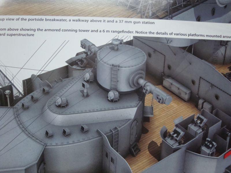
Hello all, Hello Michael, hello Grant, Hello Brian, Hello Daniel, Thanks for looking in and for the kind words. Yes, although the ship's main items are constructed from cardboard, all the detailing is made from aluminium, brass copper, styrene, spring steel, pvc, resin and spring steel. We always organise our scale model exhibitions at the Malta Maritime Museum, and the curator together with his director, would like to put their hands on it, but shall do so after entry to the afterlife. Yes the radar installation at last. It's a long session as there are quite a lot of pics to post.
-
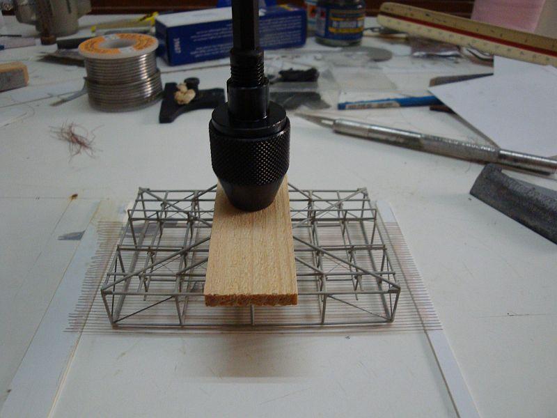
Hi guys, got some more time, so here goes the second part. A view from the front. The base coat applied. A view from the rear. An elevational view. A close up view. The start of the finish - the first copper wires forming part of the radar protective mesh. The full set. A longitudinal view. The radar is placed on the copper wire assembly, with a little help from the mini chuck. This adds some weight to the assembly, to keep it in place under tension, until the super glue dries up. The protective mesh is ready for the application of the next coat of primer. A close up view. Will be posting the pictures for the FuMB SAMOS4 Radar tomorrow.
-
Hello all, Have some time to spare, so I am posting the construction pictures for the FuMO 27 Radar, which formed part of the main radar installation on board the Scharnhorst. The materials used are copper wire, styrene rods, brass, steel wire, and other styrene profiles. Here goes, The bases of the dipoles assembly punched out from styrene sheet. The main base frame with the protective frame support struts. The main base frame in it's actual position. The protective cage under way. The protective cage ready for the next step. The back side stiffener supports. The cross mesh made from copper wire. Note also the corners, the bases and the first di-pole assembly. The full set of di-pole assemblies in place. The radar assembly with spring steel wire supports at the ends. A closer view. A rear view. The full support structure of the radar, together with the main electrical junction box, access ladder and grab rails. A closer view. Shall try to post more.
-
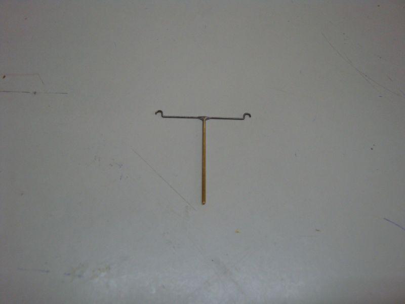
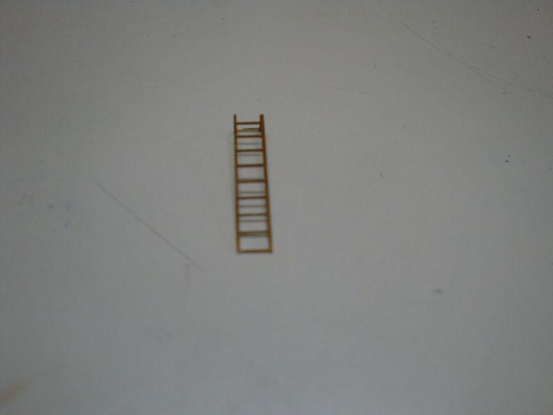
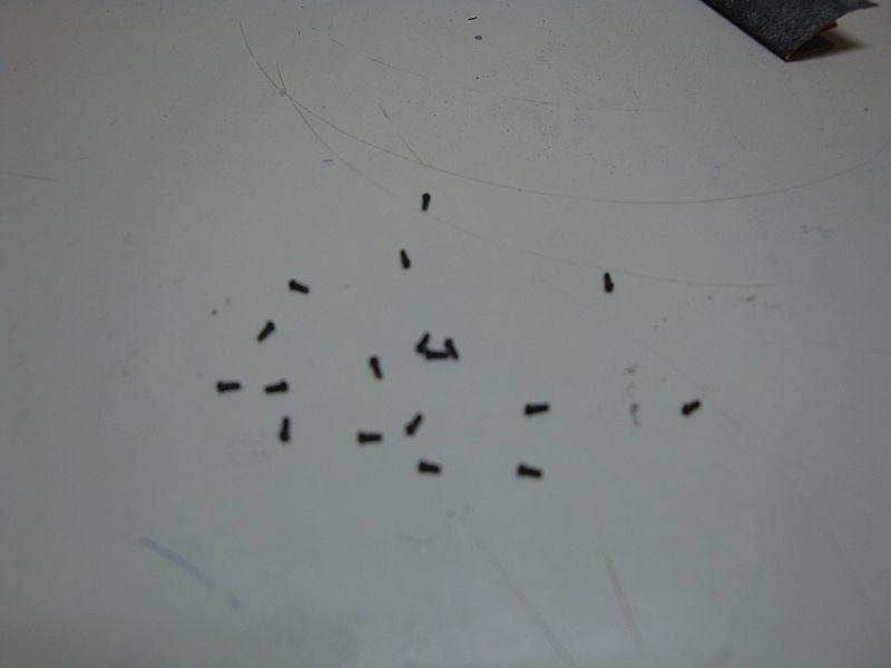
Good morning all, Today, I am posting the second part related to the construction of the ship's forward range finder. Here goes: The range finder base with it's respective holding down bolts. The range finder structure is now complete. The T-arial, made from brass and spring steel. The first armour plating strip in place. The photo-etch brass ladder. The arial in place. An overall priming coat. The armour plating strip, with the holding bolts in place. Another view. The second primer coat The lock bolts as supplied by CMK. The second armour plating strip in place. The locking bolts in place. A front view. The range finder, set in a vertical position, to allow fitting of the locking bolts required for the range finder locking flange to the housing. The locking bolts - 0.6mm diameter. The first few in place. The first flange is ready. The access ladder in place. The final coat of primer coating. Water sprinkler pipework. This was used to defrost the ice which used to gather around the range finder lens housing. A front view. An elevational view.
-
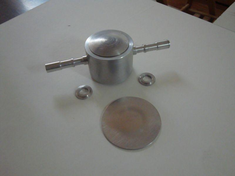
Hi Guys, Will try and post some more pics. These are related to the range finder which is situated on the armoured bridge of the forward superstructure. Here goes. A view of the 7mtr range finder as depicted in the Kagero book. The basic parts required, made from aluminium and turned on my lathe. The range finder beginning to take shape. A side view. An elevational view. A close view. Another close view. A close view from the front. The circular headed locking bolts as supplied by Special Hobby. The first set of bolts in place.
-
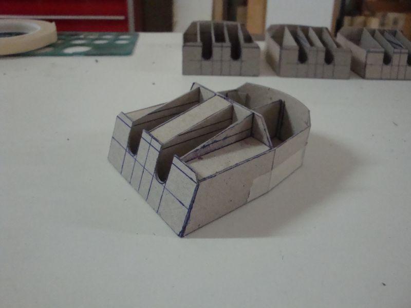
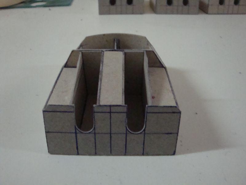
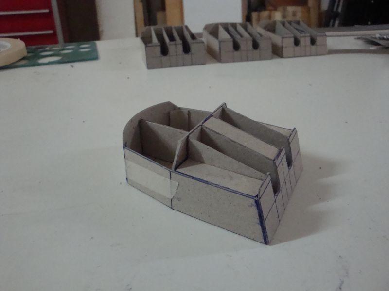
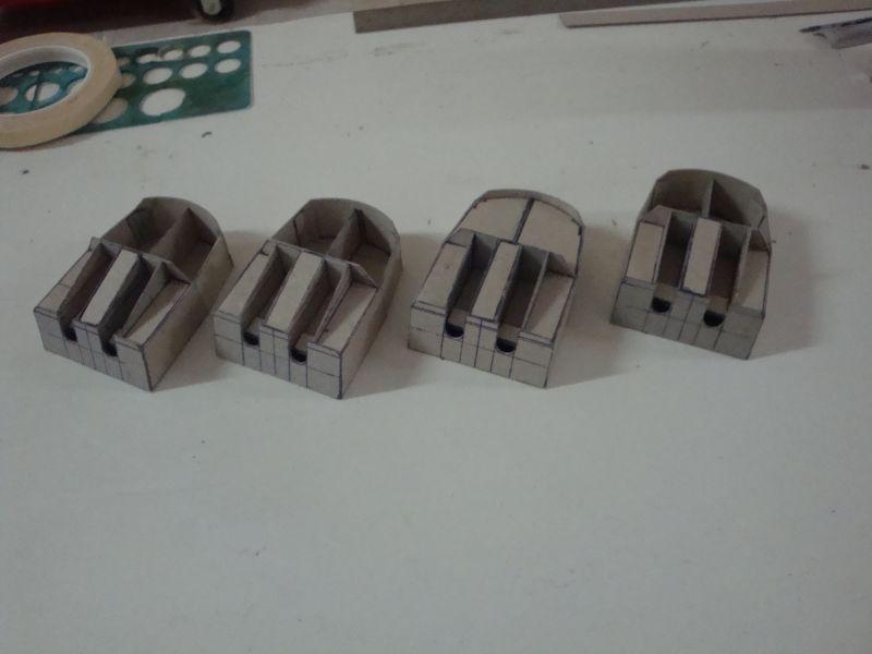
Hello all, I am still the only one in the office, so I can post some more pictures. I am now posting the pictures related with the construction of the aircraft storage hanger. The ship was equipped with three Arado 196 float planes. One was always situated on the catapult, while the other two were sited cosy in the hanger. Here goes. The base enclosure of the hanger. A side view. A rear view. The roof skin fitted in. A rear view. An elevational view. A close look - note the cardboard semi circular support beams. A view from the top, revealing clearly the limited space for the storage of the two aircraft. The aircraft hanger in place. A view from the rear. An elevational view. Planning out the air exhaust vents, located at either side of the hanger. The four main pieces required for the job. A view of the vents. Another view. An elevational view of the hanger with the side ventilators. Another view. See if I can spare some more time to post more pics.
-
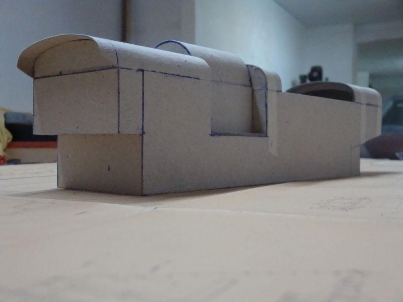
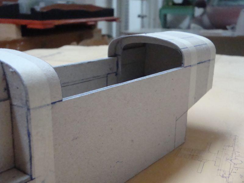
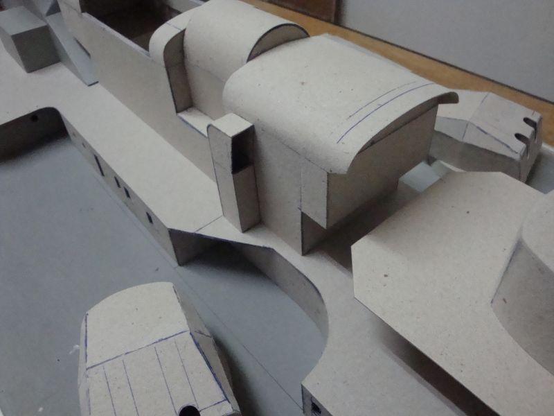
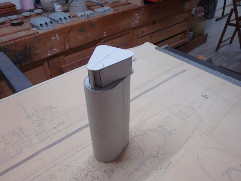
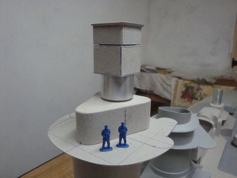
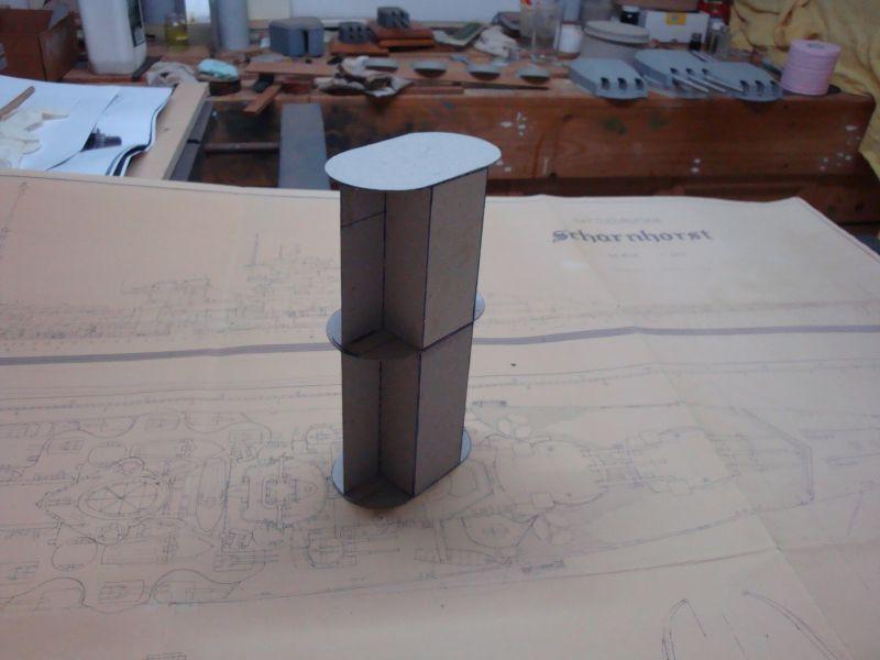
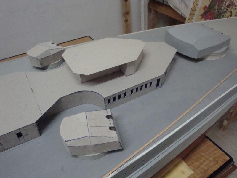
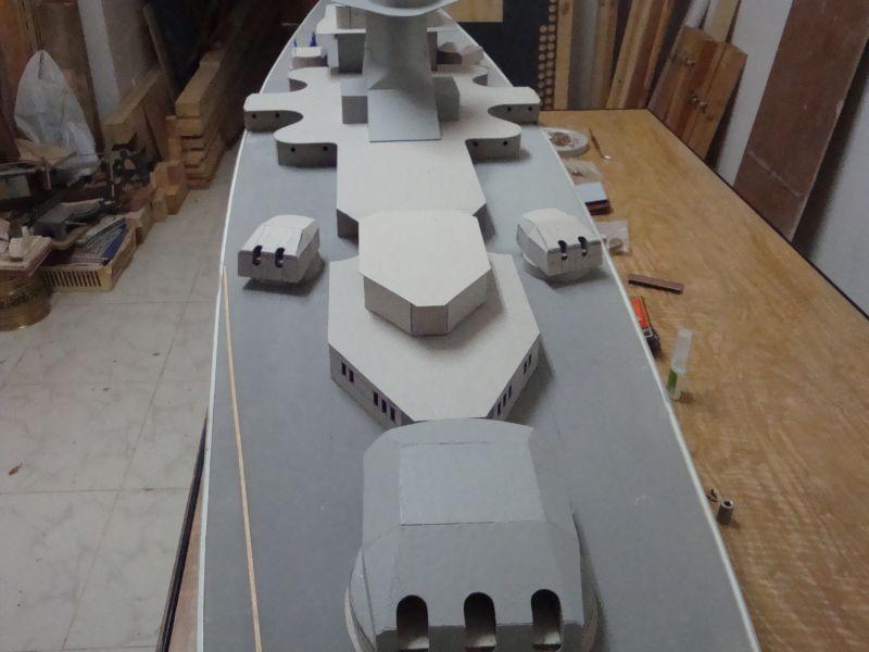
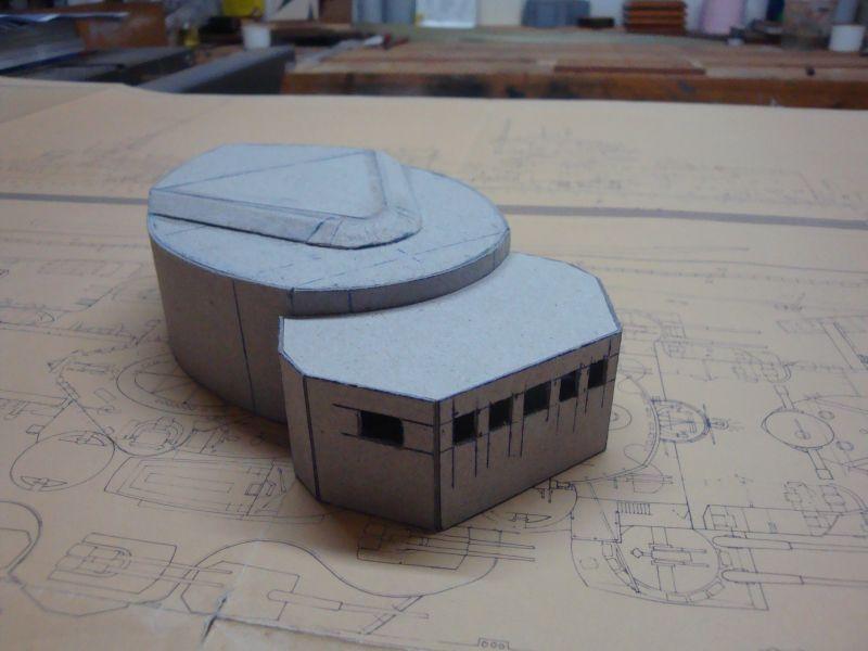
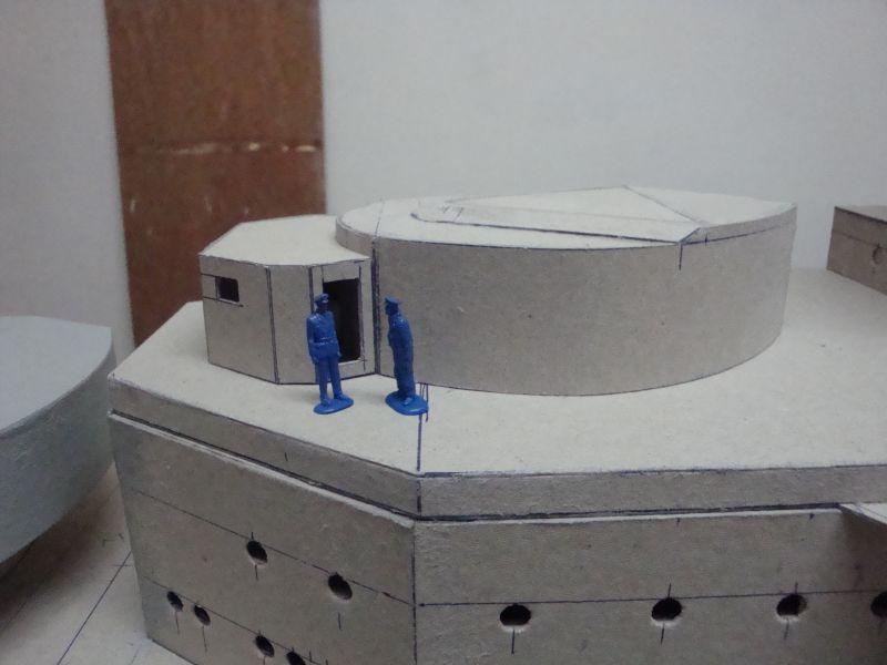
Good morning to all, Hello Peter - The ship shall bear an overall weight of 25 to 30 Kgs when ready. The overall length of the model is 3260mm. Hello ben - thanks for looking in and for the kind words. Today I am posting the second part related with the construction of the tower. Here goes. An overall view of the tower with the double skin applied. The base of the armoured observation post, on top of which shall sit the forward radar installation. The middle partition and the first side and rear skins. An overall view. The side walls are in place, together with the top and bottom plates. An elevational view. The armoured observation post placed on top of the tower for comparision. The base of the open top observation balcont, which sits on top of the tower assembly. The second skin applied. Another view. Another view. The three stouges - the tower + the Balcony base and the armoured observation post. A view from the front. A close view of what is yet to come - the radar assembly. Will post more soon.
-
Hello Foremast, First of all - brilliant work. it's good to see something different for a change. Not many construct ships of that period. I will surely follow your build. Great deck planking too.
-
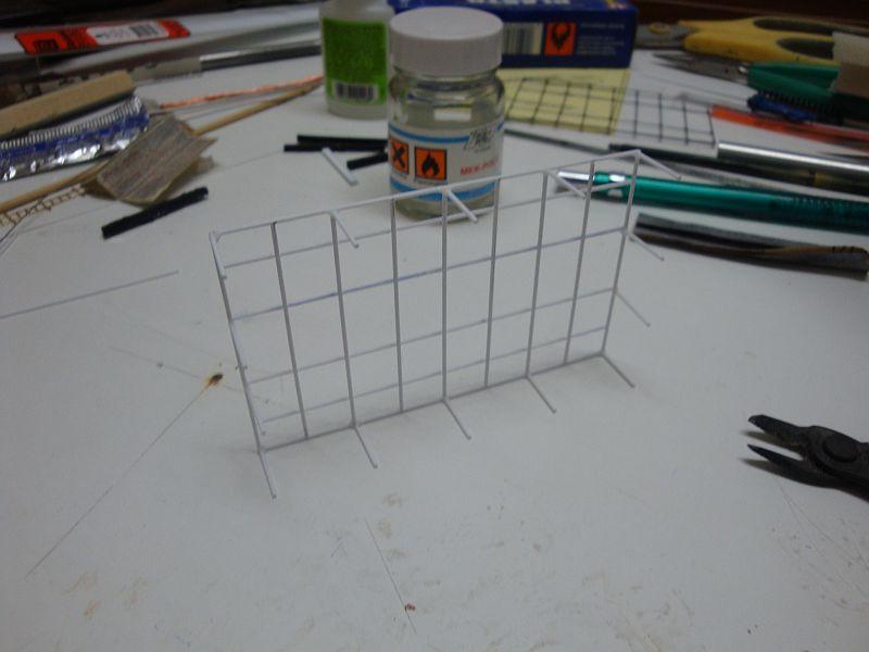
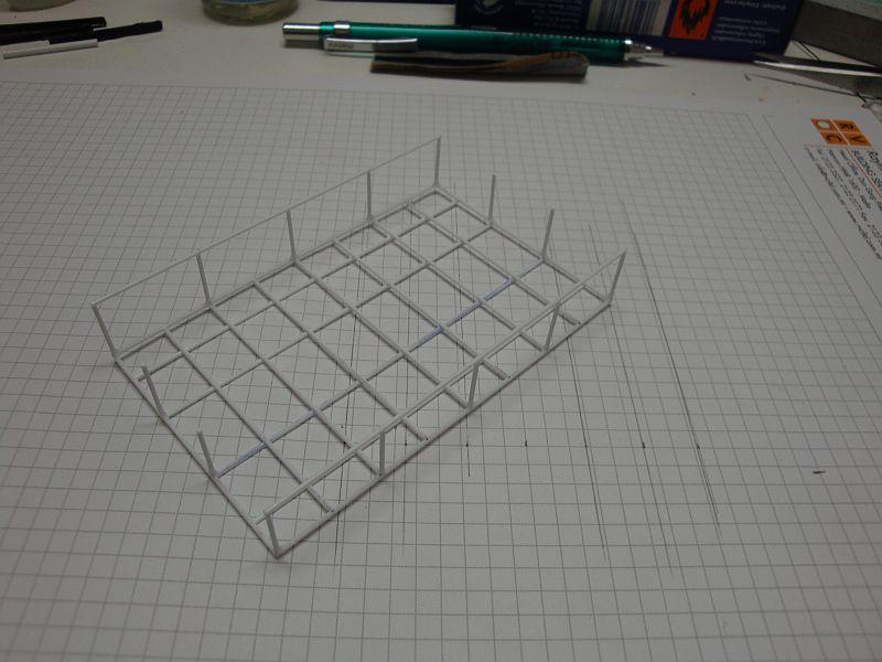
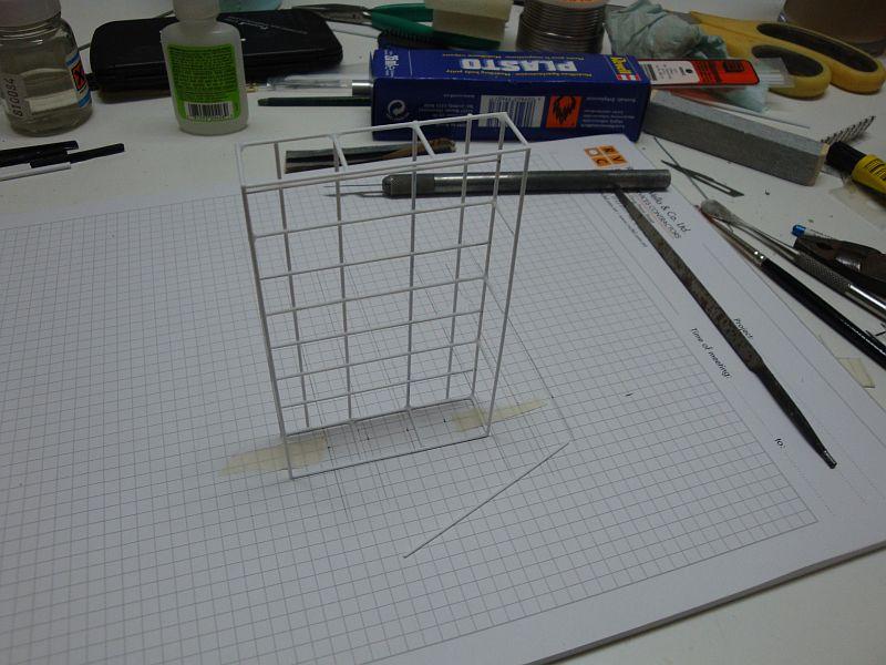
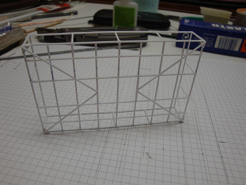
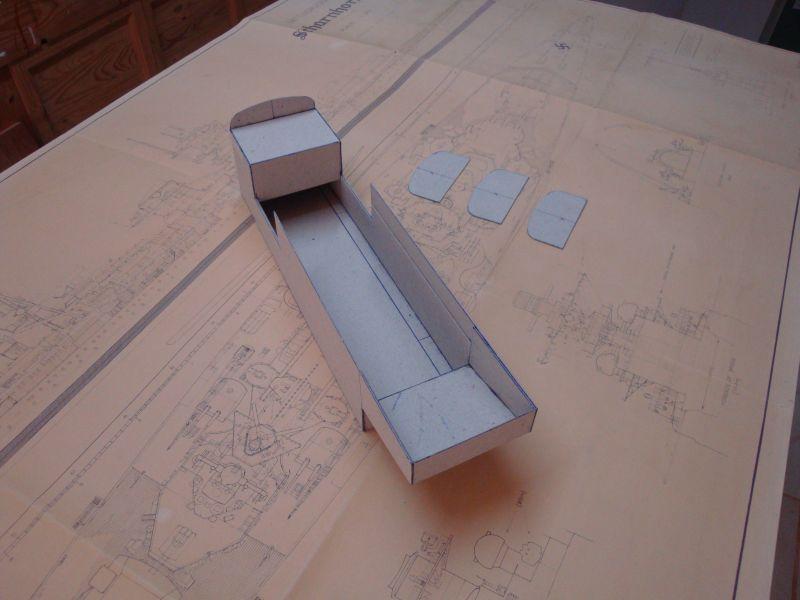
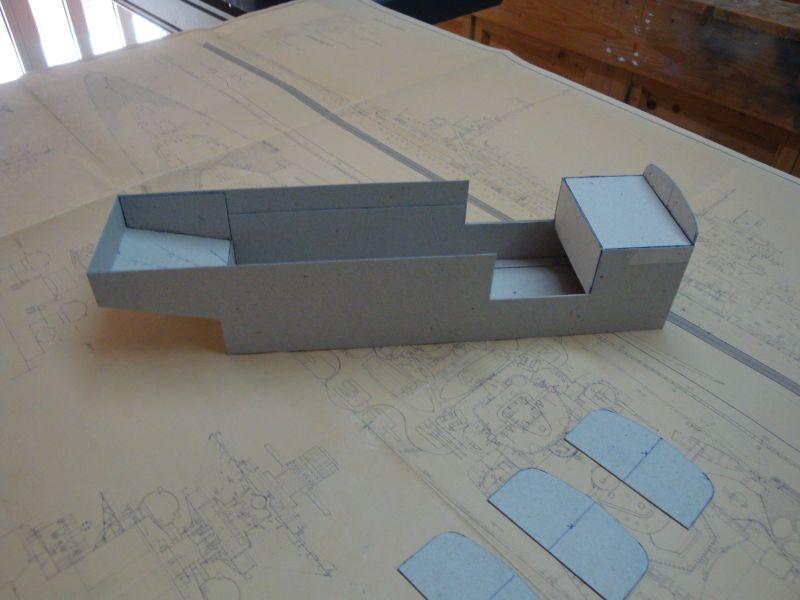
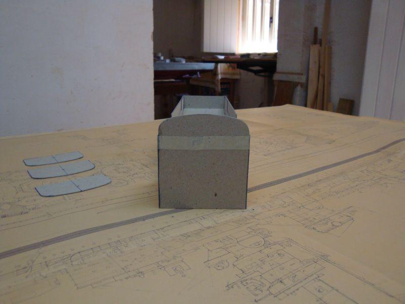
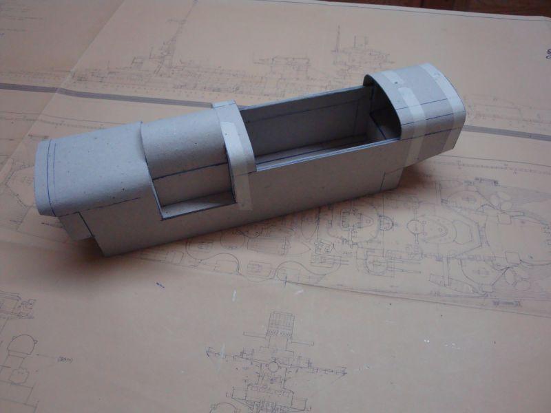
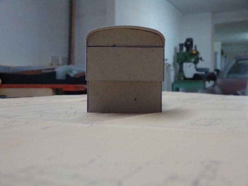
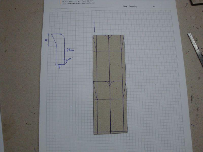
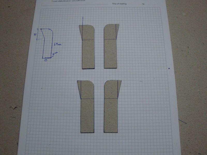
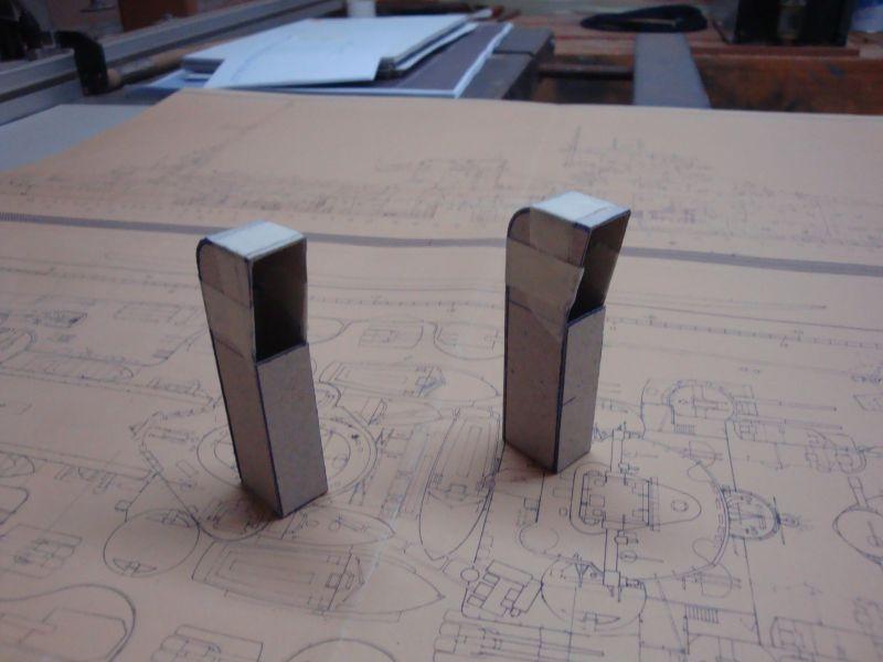
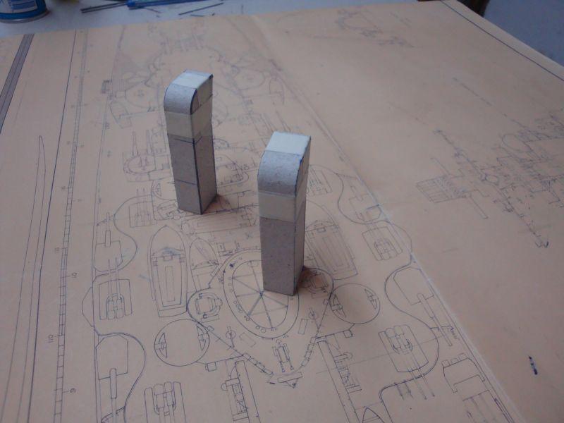
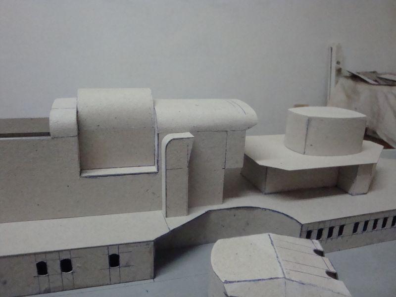
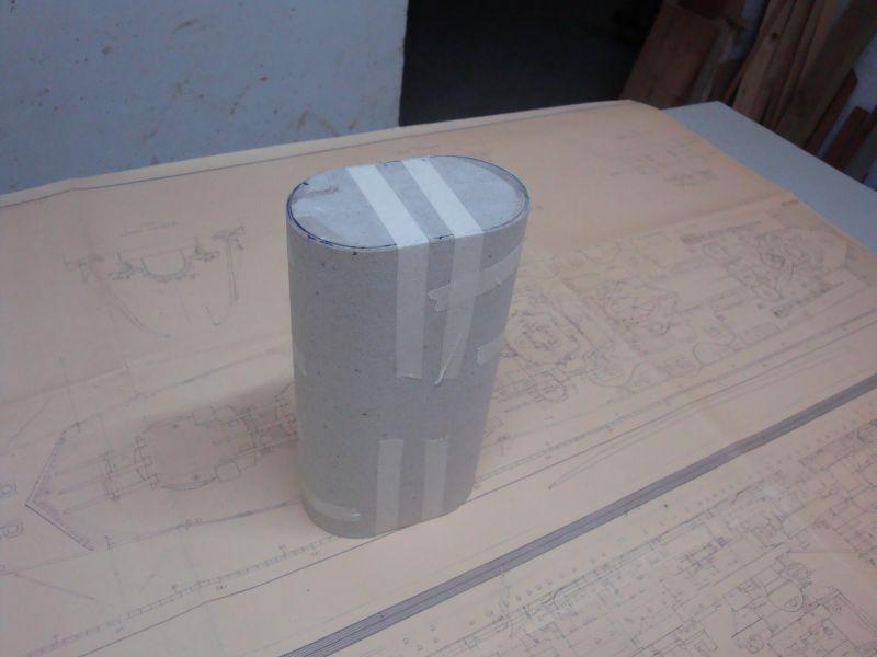
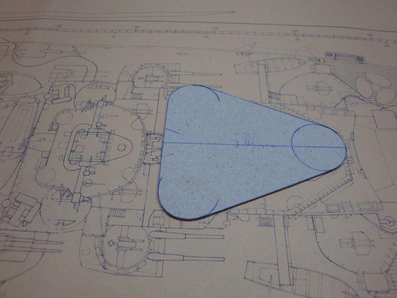
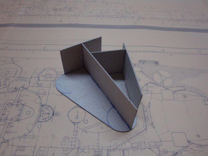
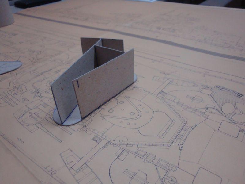
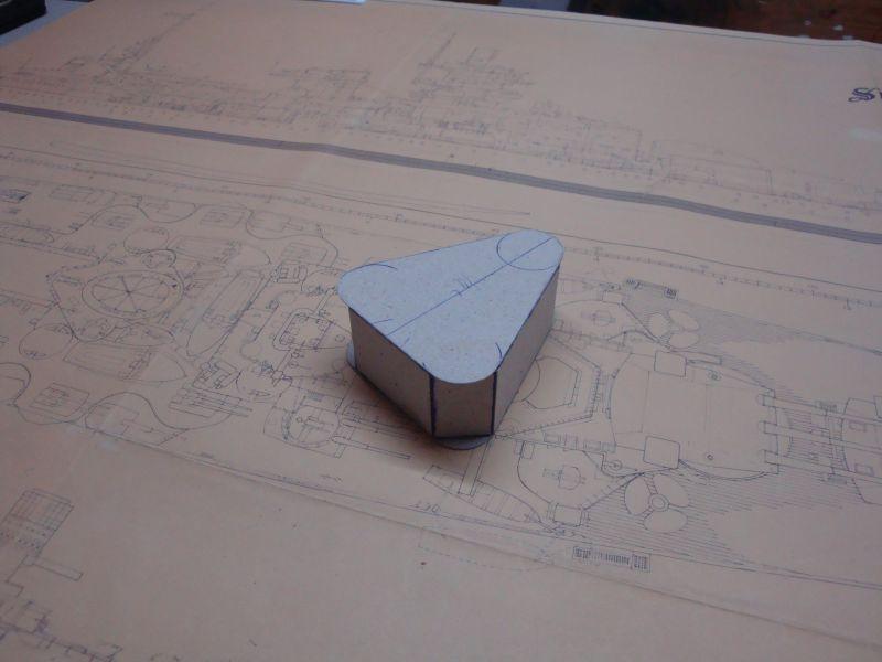
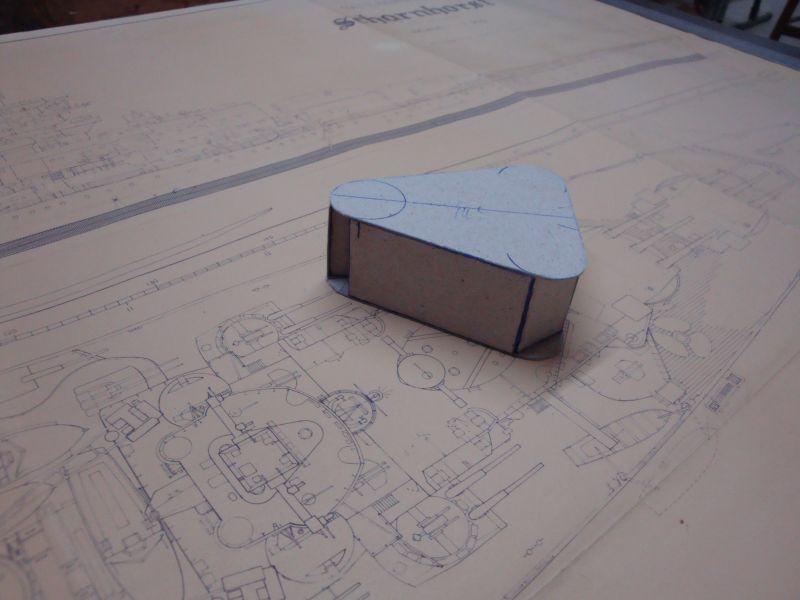
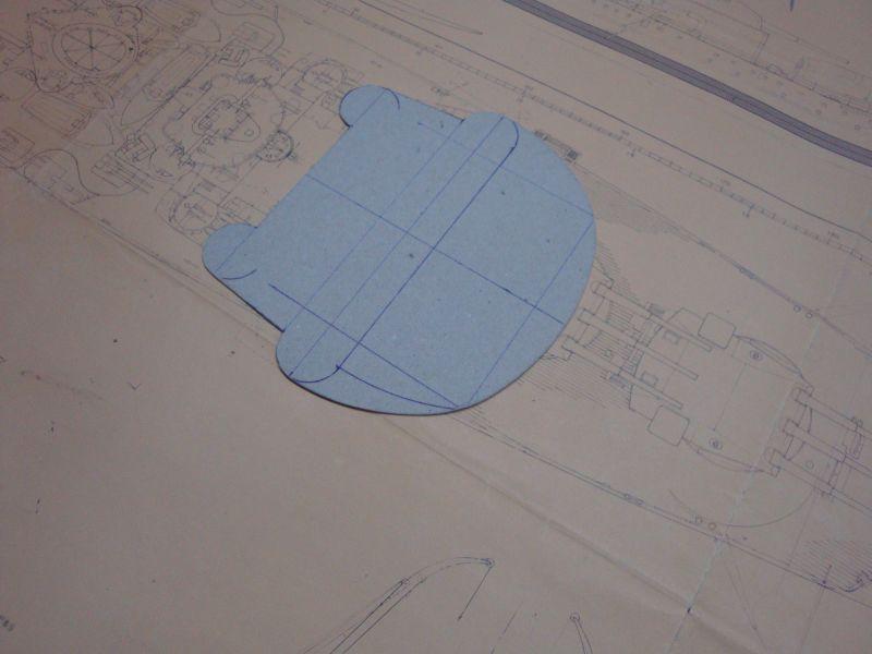
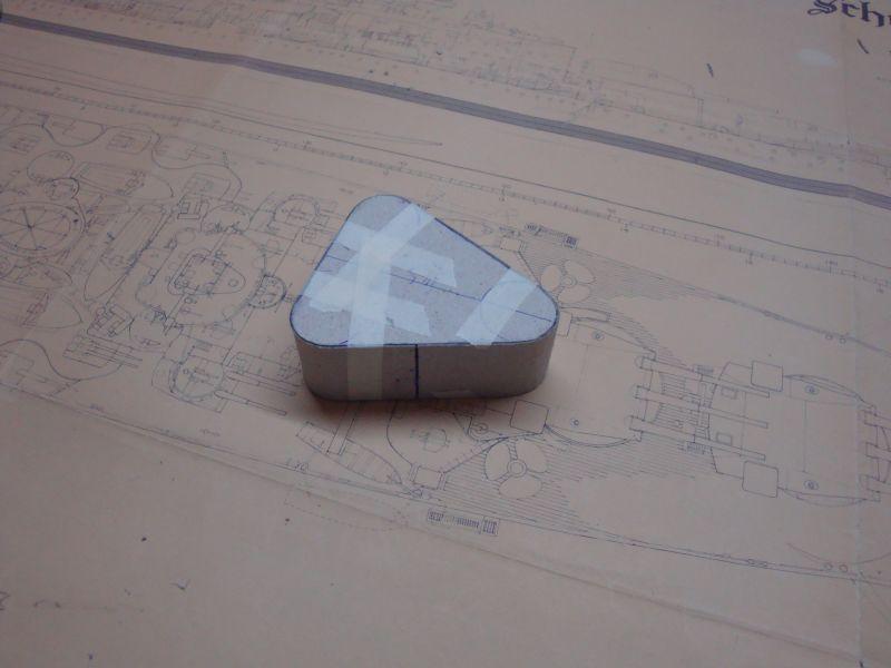
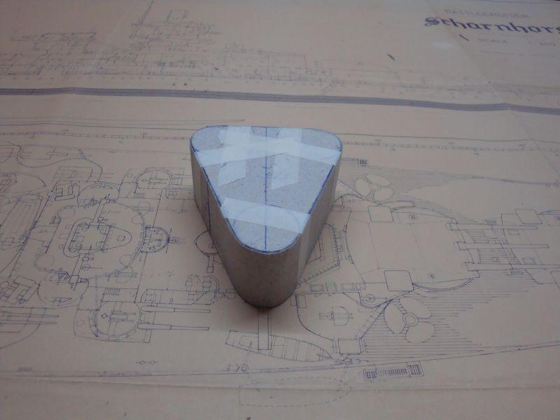
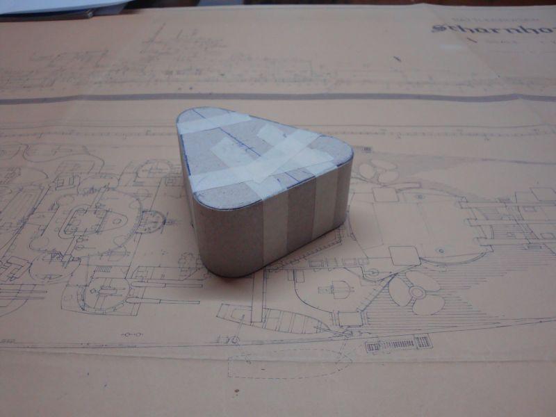
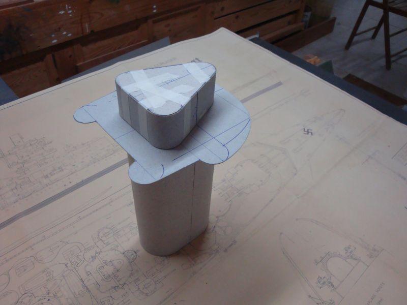
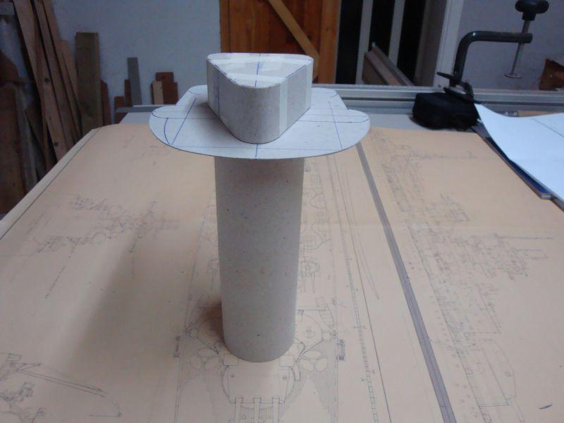
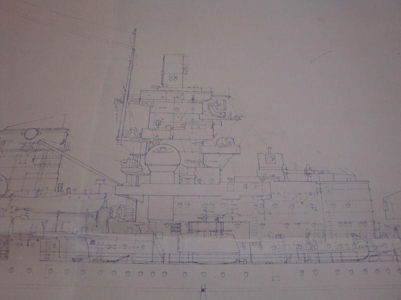
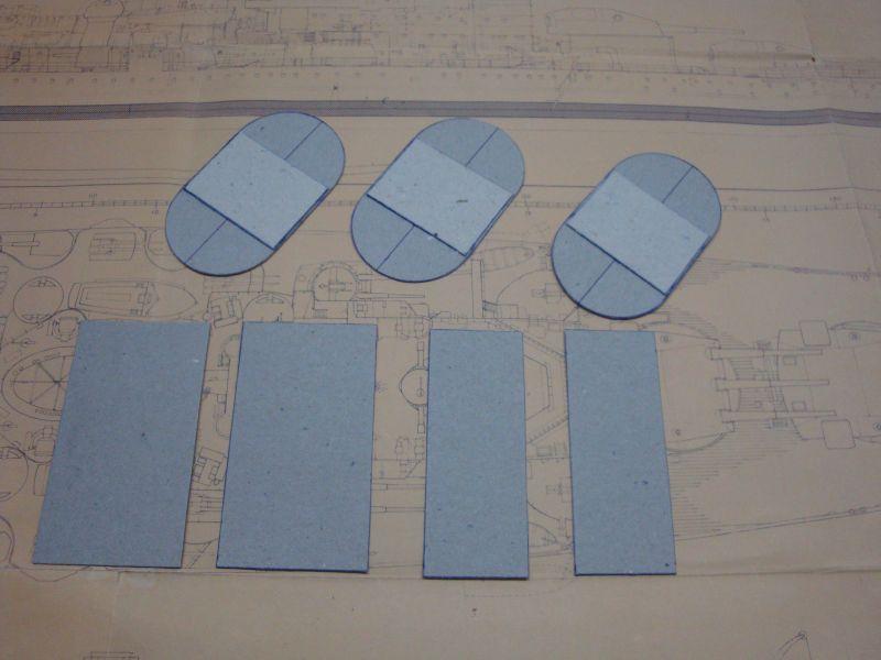
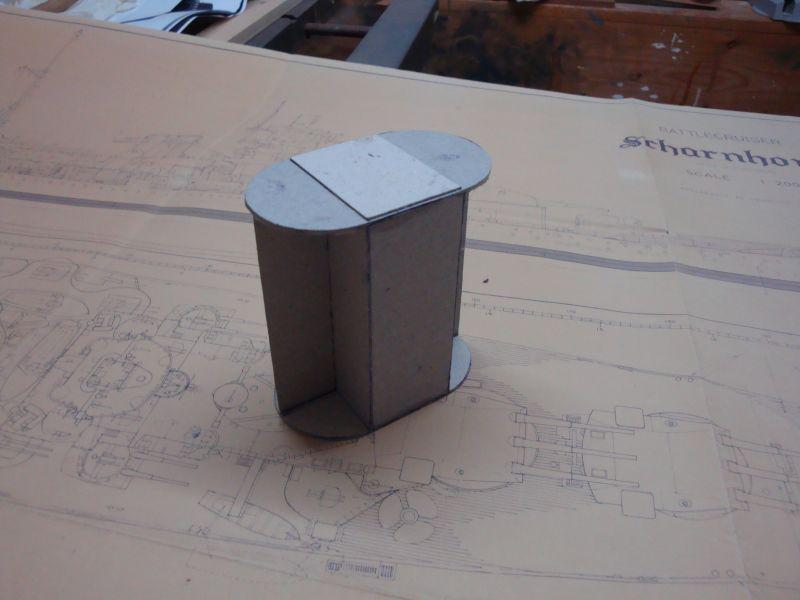
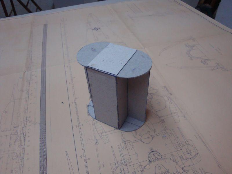
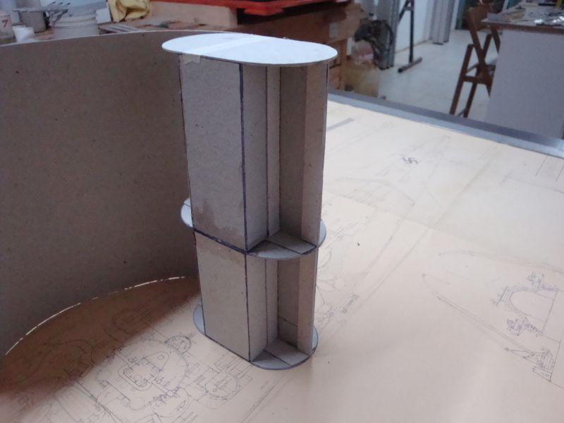
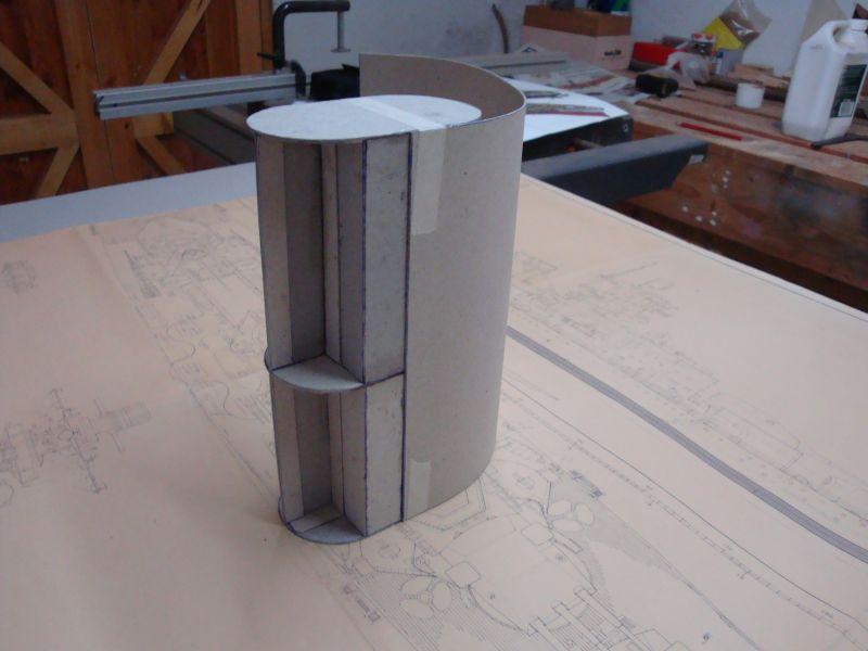
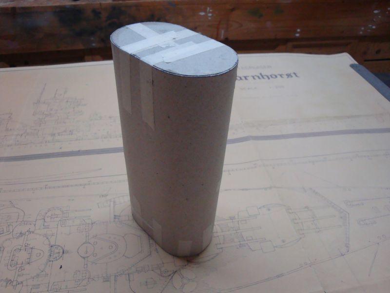
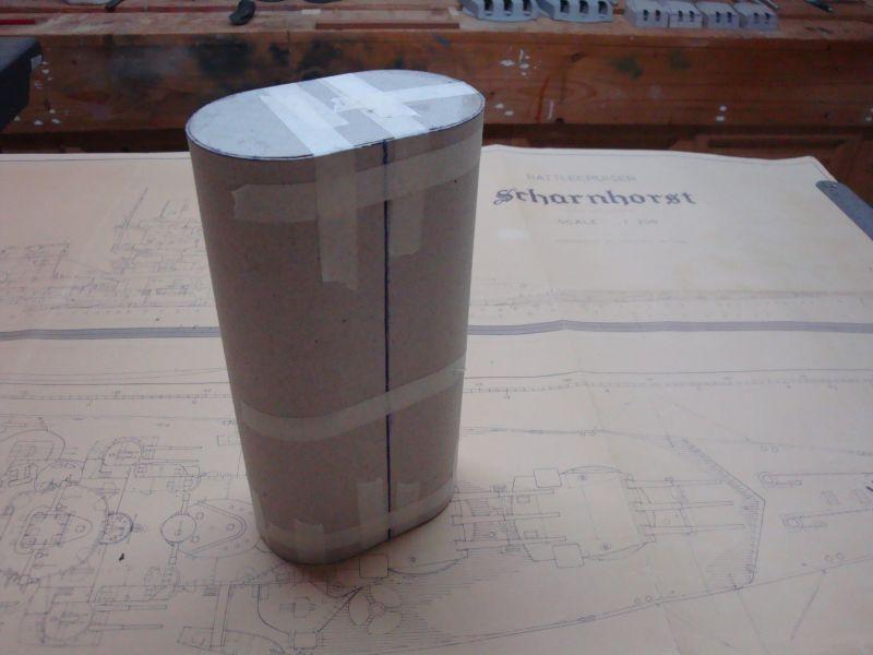
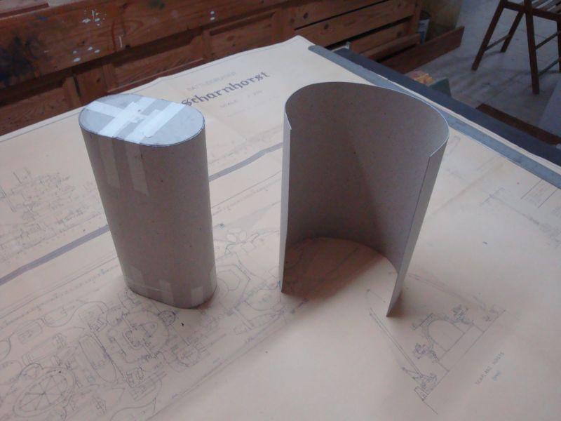
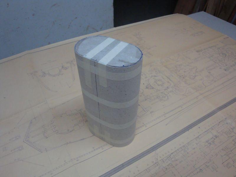
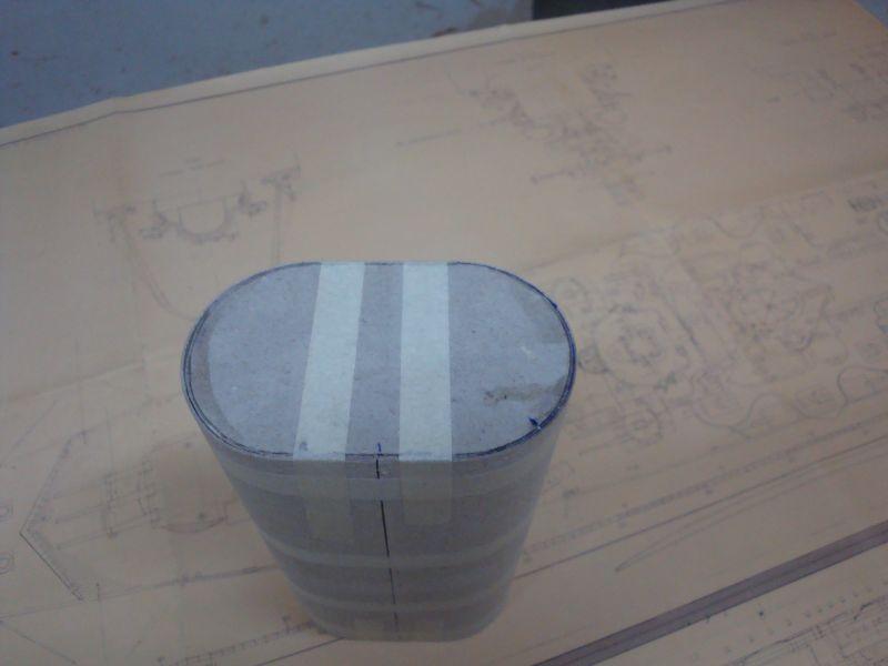
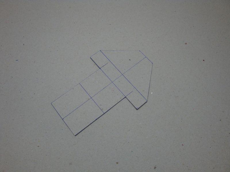
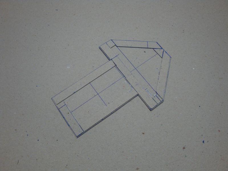
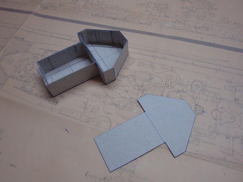
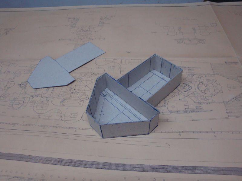
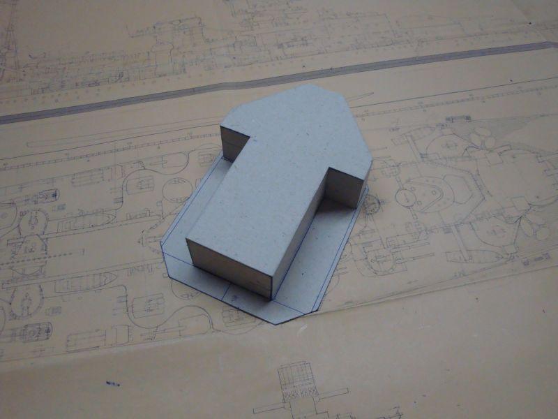
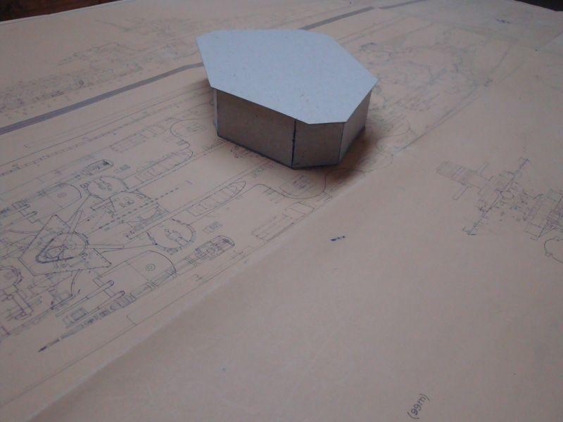
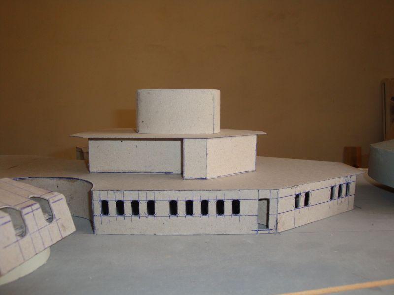
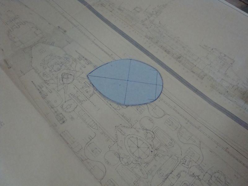
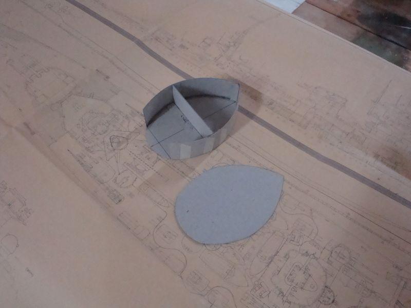
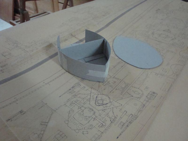
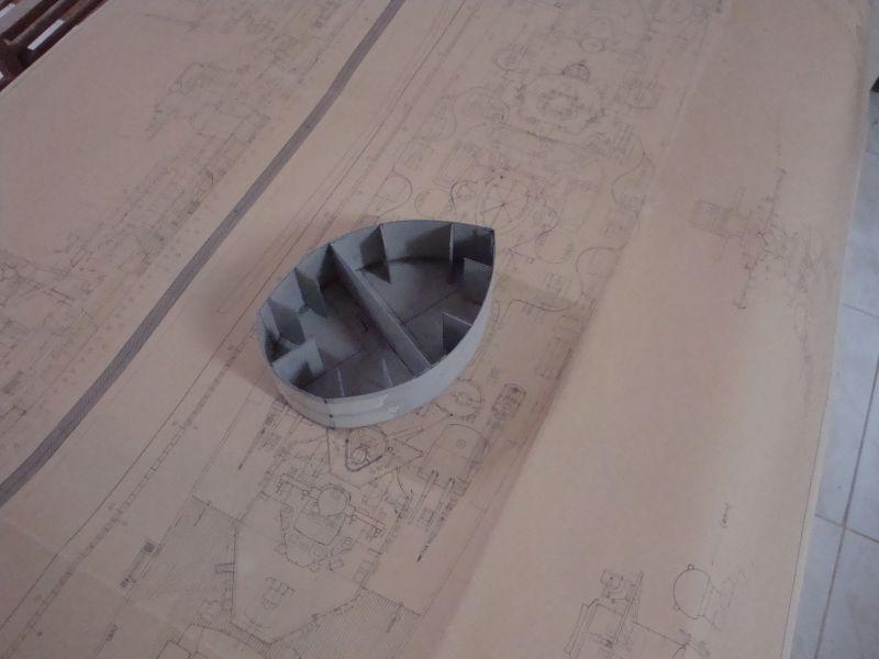
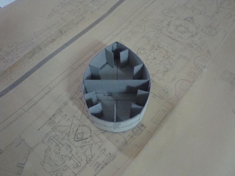
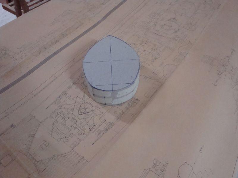
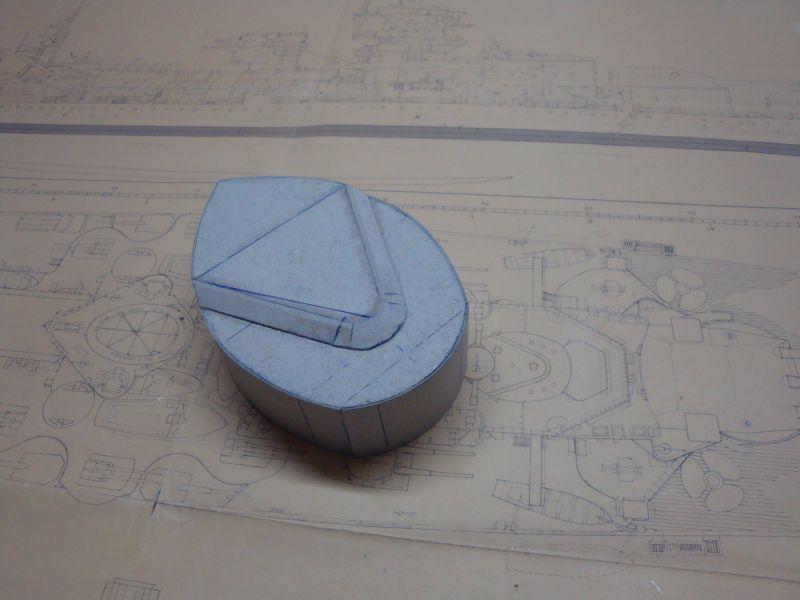
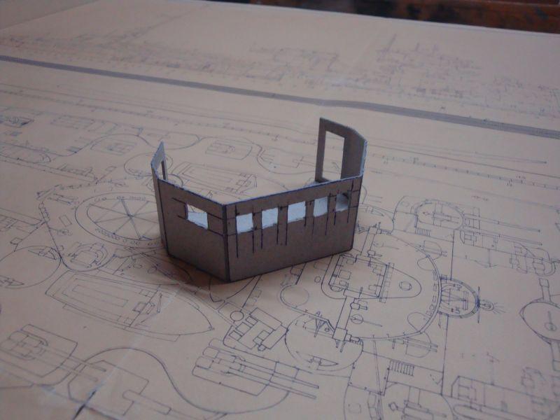
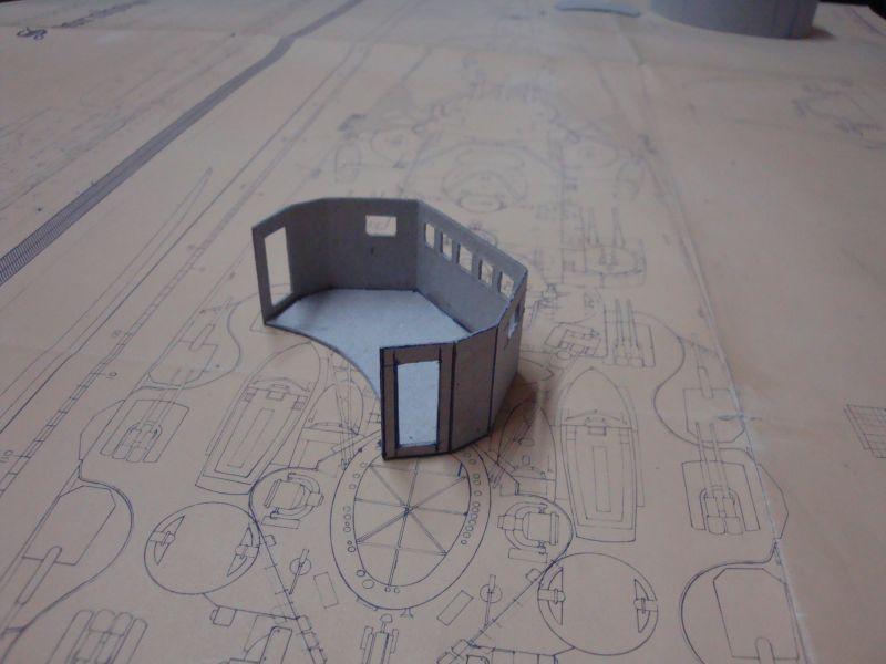
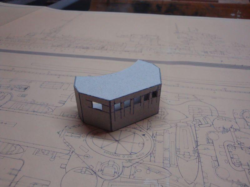
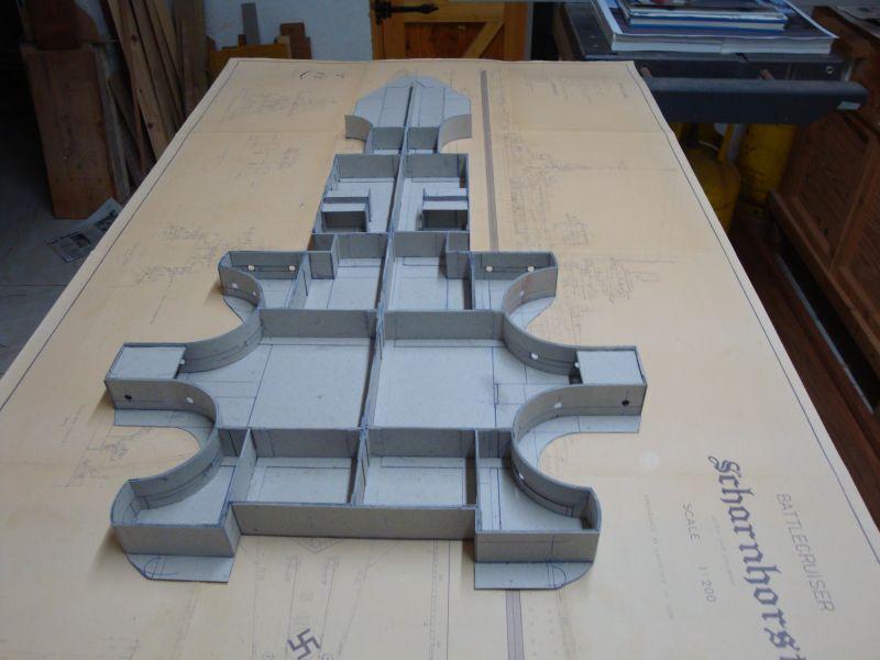
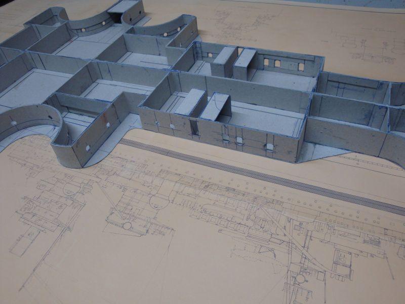
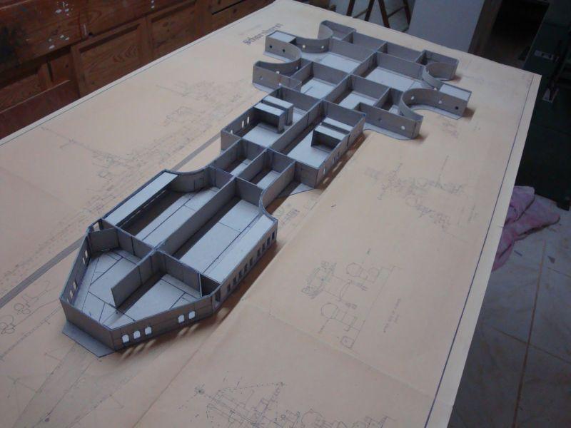
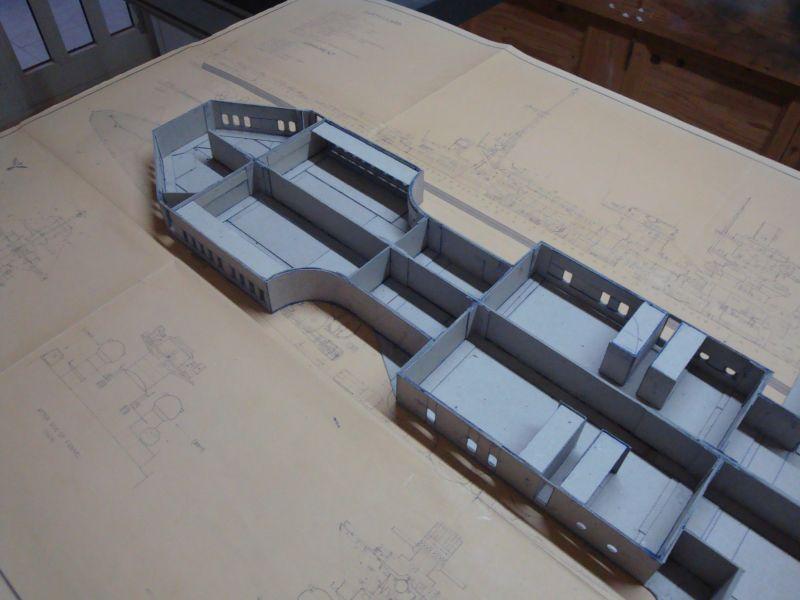
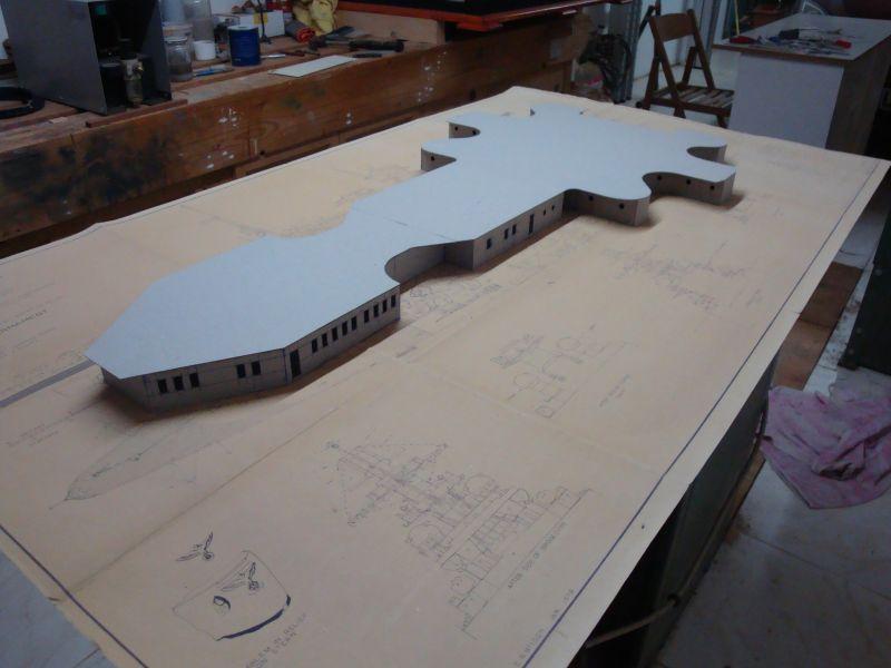
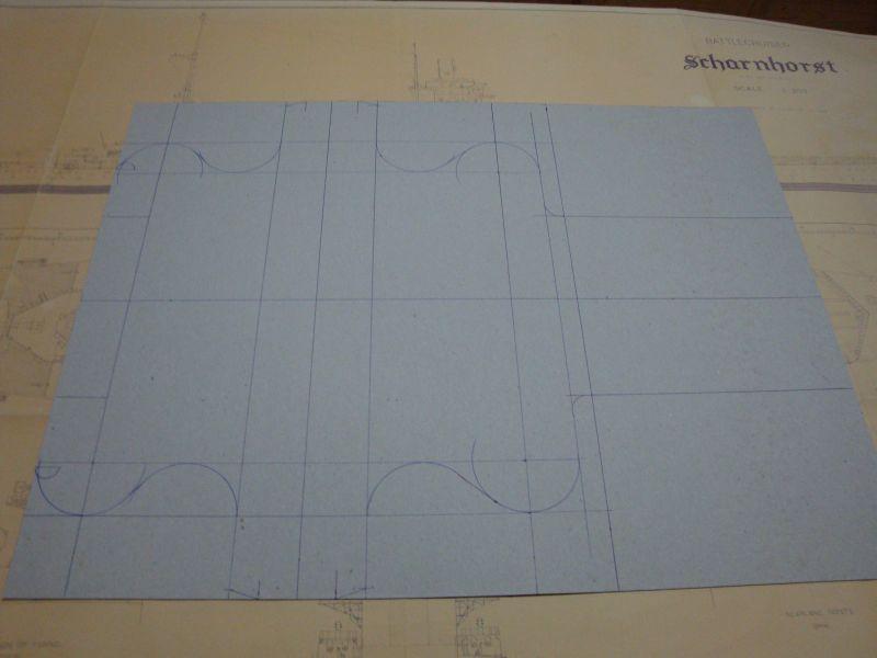
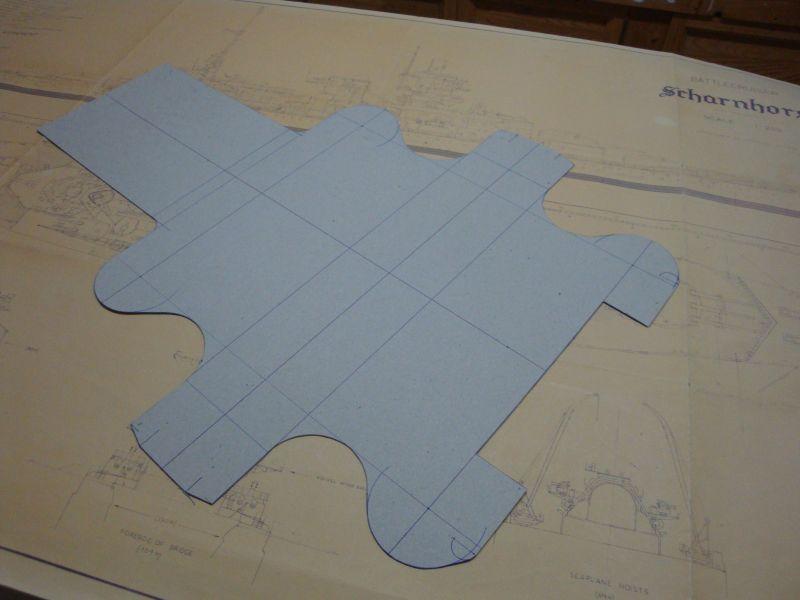
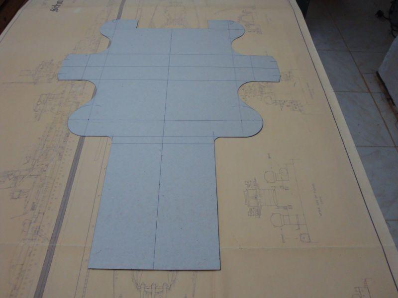
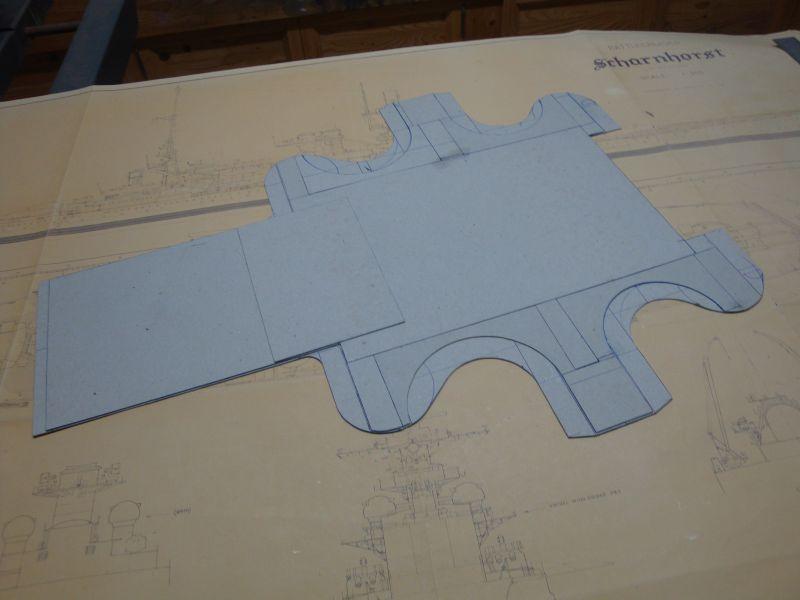
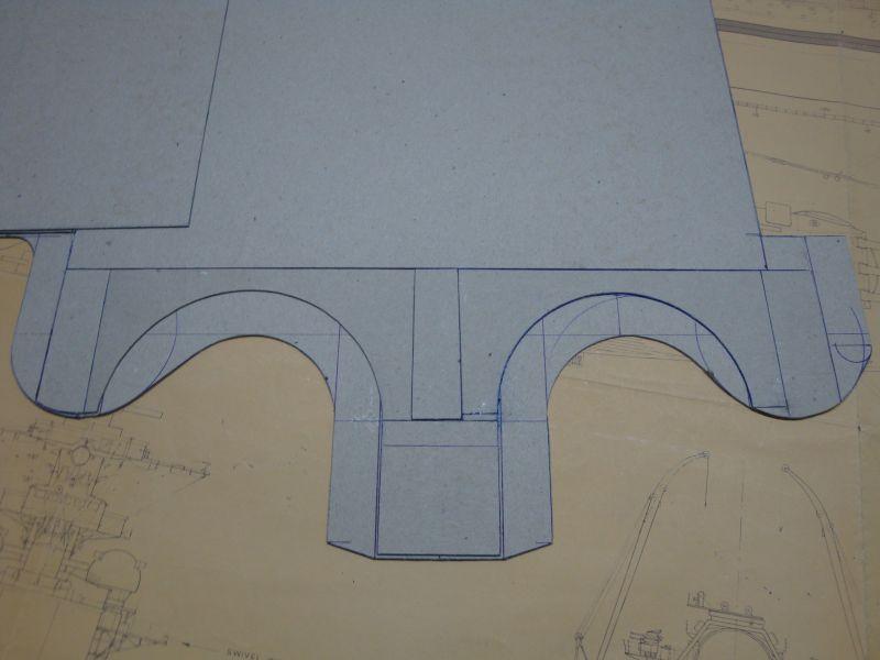
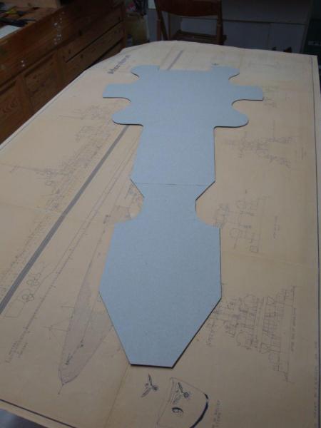
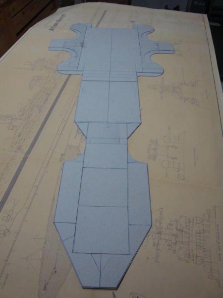
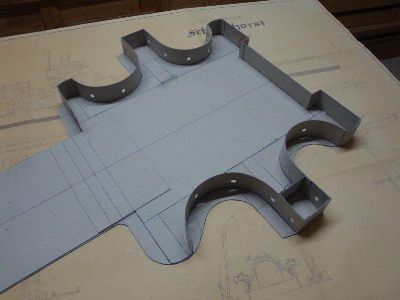
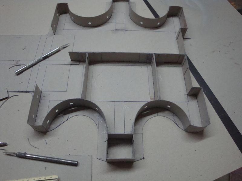
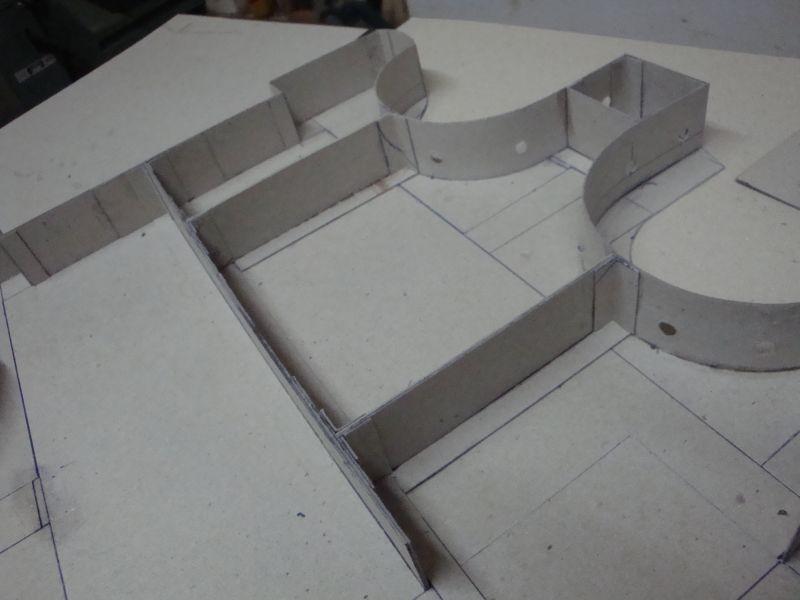
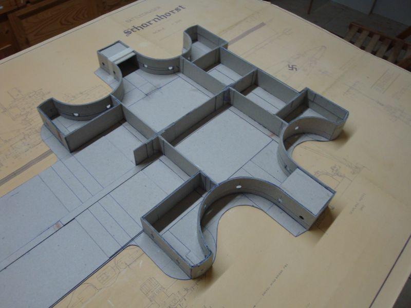
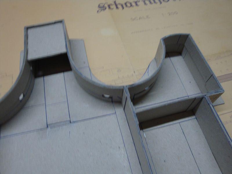
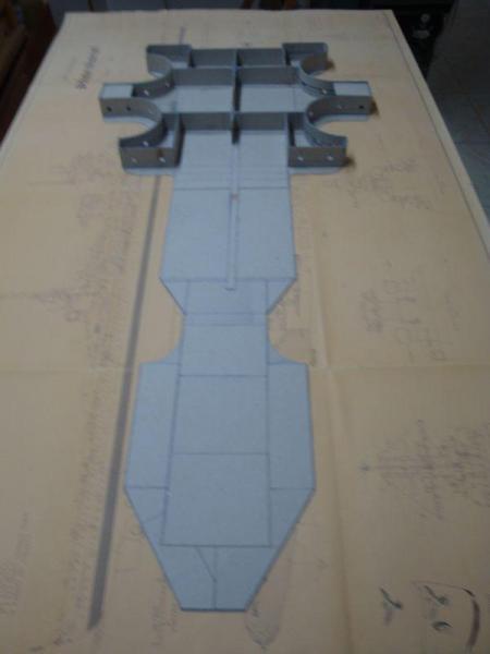
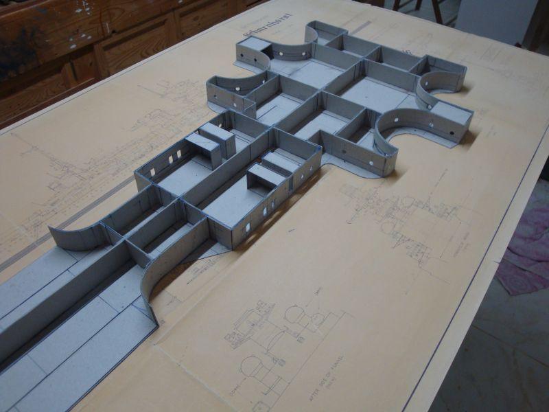
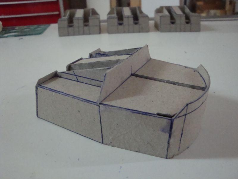
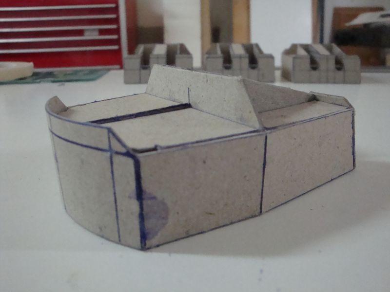
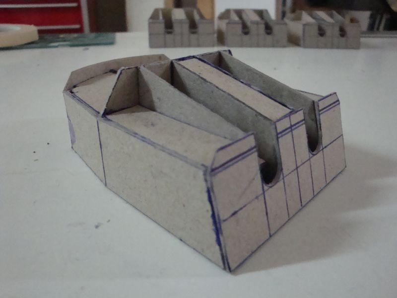
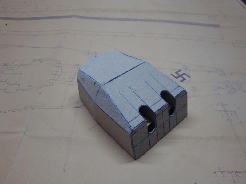
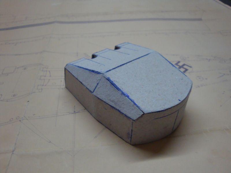
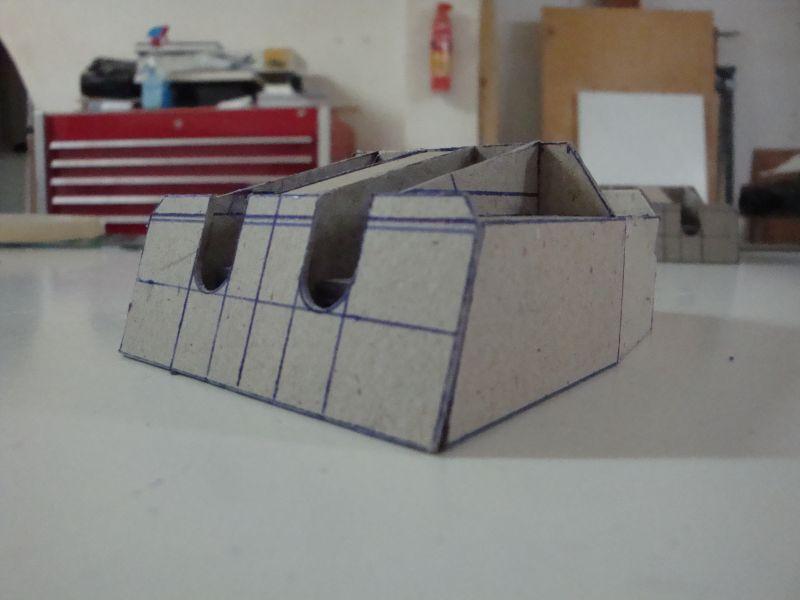
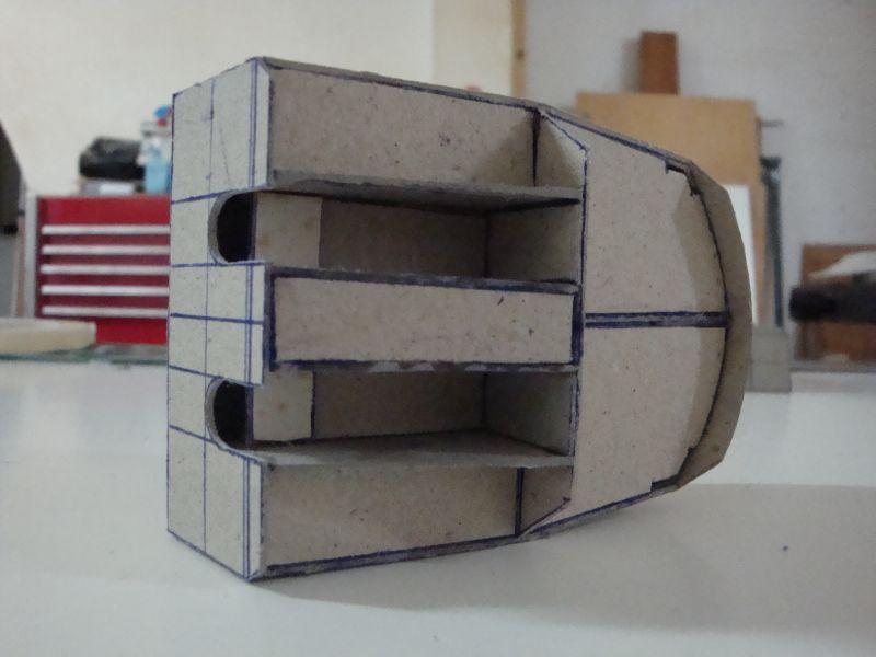
Good morning all, This morning I am posting the progress pictures related with the construction of the tower, on top of which the famous radar installation shall be sited. Here goes. A view of the scale plan of the tower. The primary pieces required to create the base shape of the tower. The first structural piece. The second structural piece. The two pieces mounted on top of each other, to from the support structure. The first skin fitted on. Another view of the process - note the stiffeners applied to the basic support structure. The fist skin wall is ready. Another view. The second skin wall, is ready to be fitted in place. The second skin in place. A closer view - note the two thicknesses of the 1mm thick cardboard used. Shall be posting the second part in due course.
-
Good morning all, Hello Pat - Thanks for looking in, Yes, I shall be posting all the progress pictures, and of course the radar shall be included. I also have to include the new progress pictures as well. Hello John - Well said - That is exactly what I have been trying to point out. History is history, and cannot be mixed up with politics. Just arrived in the office, and have a site meeting this morning, so I shall be posting some progress pictures in the afternoon.
-
hello Kevin, FULLY AGREE WITH YOU.
-
Hello Daniel and Brian, Thanks for looking in and your kind interest. Daniel - To answer your question - no, I don't have any tooling or press, just my bare hands, a surgical blade, and many cuts. That's life my friend, wasn't born rich (just joking). Found some more time, so time to post more pics. These are related with the construction of the afterdeck structure. Here goes. The base of the structure. The guide strips, to aid the siting of the wall skins. Walls in place. Note the stiffeners and the second layer strips. Another view. The top deck fitted in. A view of how it should look. An elevational view of the structure in place. A side elevation view. A rear view. A close up view, showing also the armoured base room on which the rear Fumo 27 Radar shall be installed. Shall post more pictures as soon as I find some time.
-
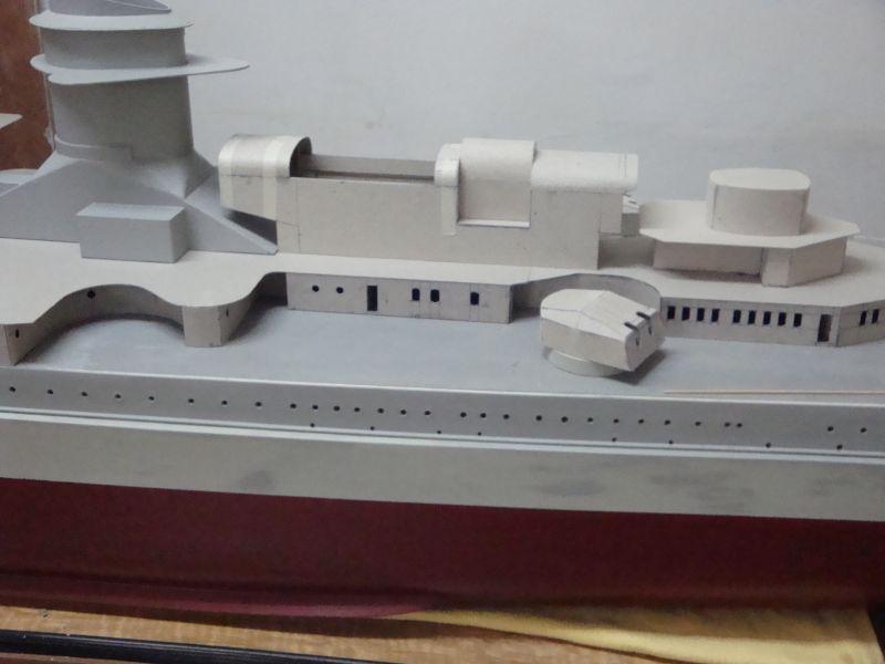
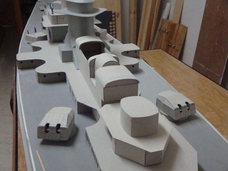
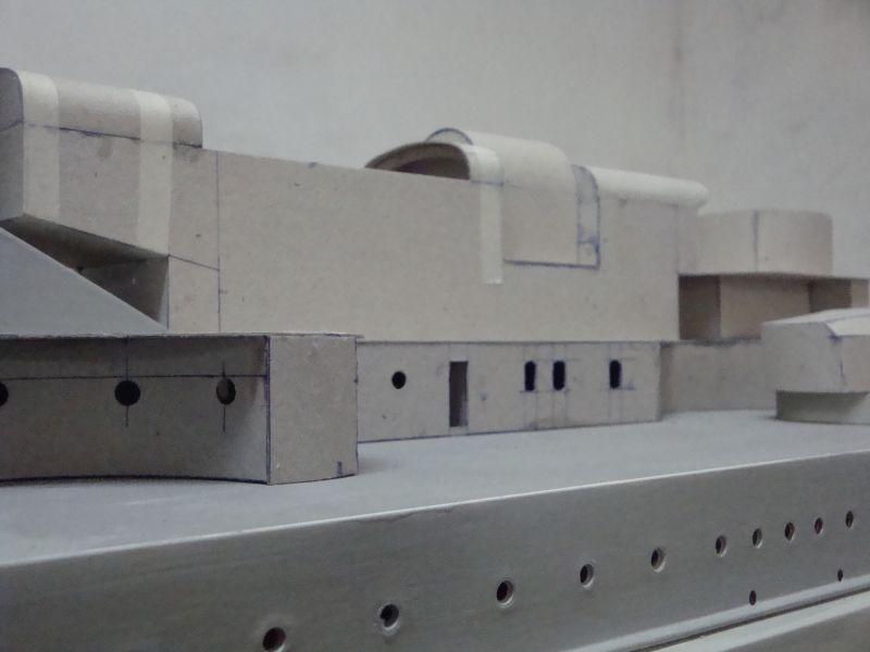
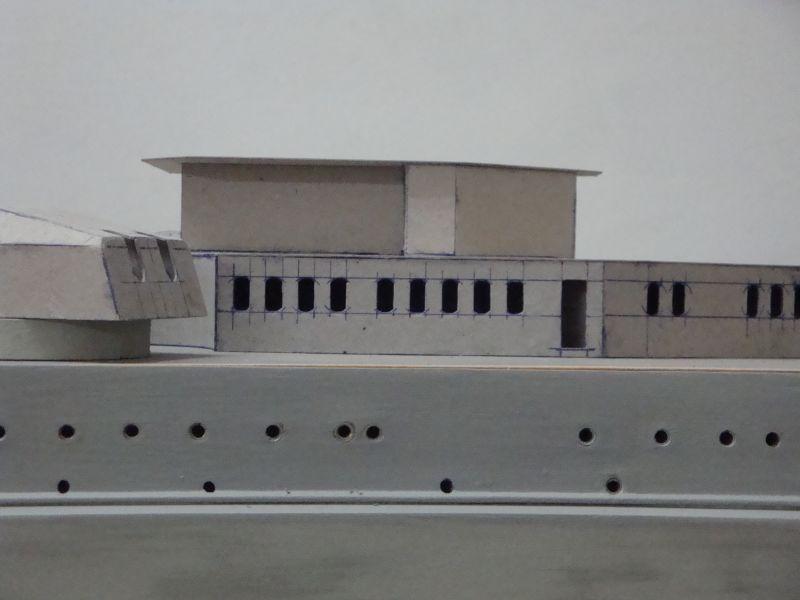
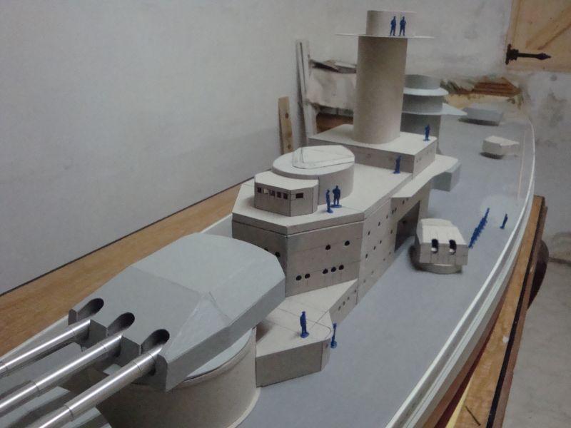
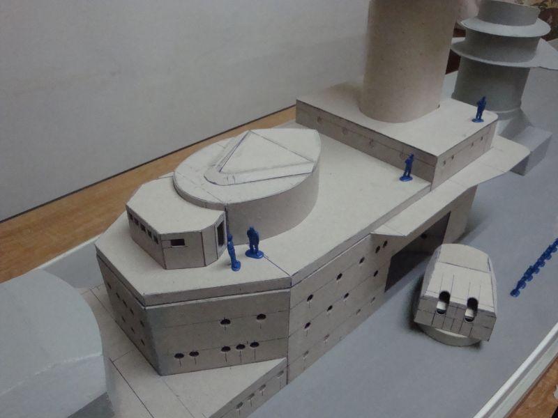
Good morning all, Well now, that is quite a discussion. yes I have to agree with your concern and curiosity. Well, I can only say one thing. We cannot mix history with politics. We are a scale modelling group of people, who share a common hobby - ships. From my point of view, weather the ship is German Russian, English, American, French, Italian, Chinese or of any other country or origin; one had to reproduce the model as was. With regards to the German Swastika, this is a rather silly situation. Today one can but a scale model kit of a WW2 German aircraft, armoured vehicle, or ship, where these all come without the cross of course; only to be purchased separately from an aftermarket decal supplier. I have only one question regards this. Is the German cross deleted just due to legal issues, or to allow these aftermarket suppliers to make more money out of our pockets? Now back to posting more progress pictures. Today, I am posting the progress pictures related to the armoured bridge, which is situated at the lower part of the forward super structure. Here goes The base of the armoured bridge. The outer skin together with the top part and the middle stiffener wall. A rear view of the construction in progress. The stiffeners and reinforcements fitted in place. A closer view. The top part fitted in place. The top section added, together with a second wall skin. A front view of the command bridge. A view from the rear. The top part added. The command bridge together with the armoured bridge. A close view of the armoured bridge in place. A longitudinal view. An arial view of the armoured bridge in place. Shall try to post more pictures today. .
-
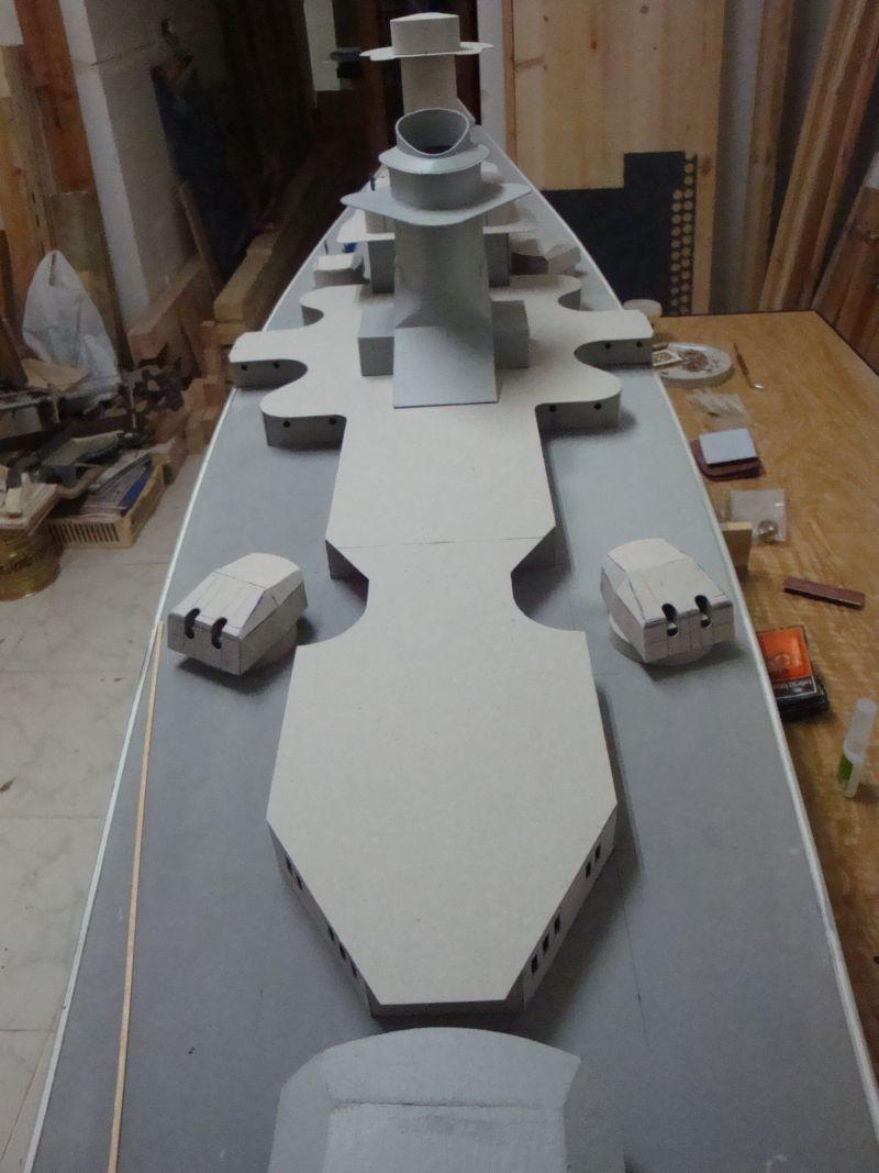
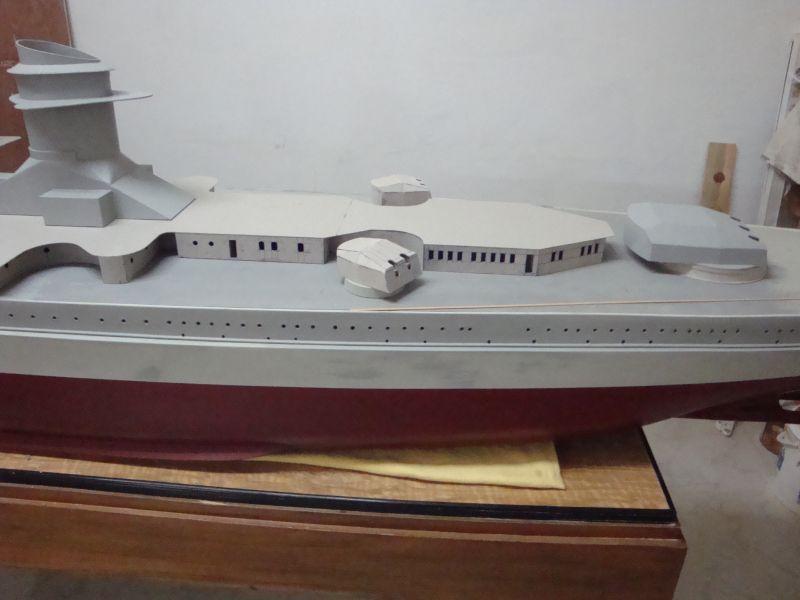
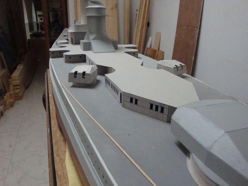
Hello all, The second part related with the construction of the midship and aft superstructure. A longitudinal view. A close view. The whole assembly is now ready for the finishing and detailing. Another view. A view of the superstructure. A close view, displaying the array of the windows. The superstructure in place. A rear view of the whole assembly. A top rear view, showing the area to be filled in with the introduction of the after structure and the aircraft hanger. Will try to find some time to post more pictures.

-
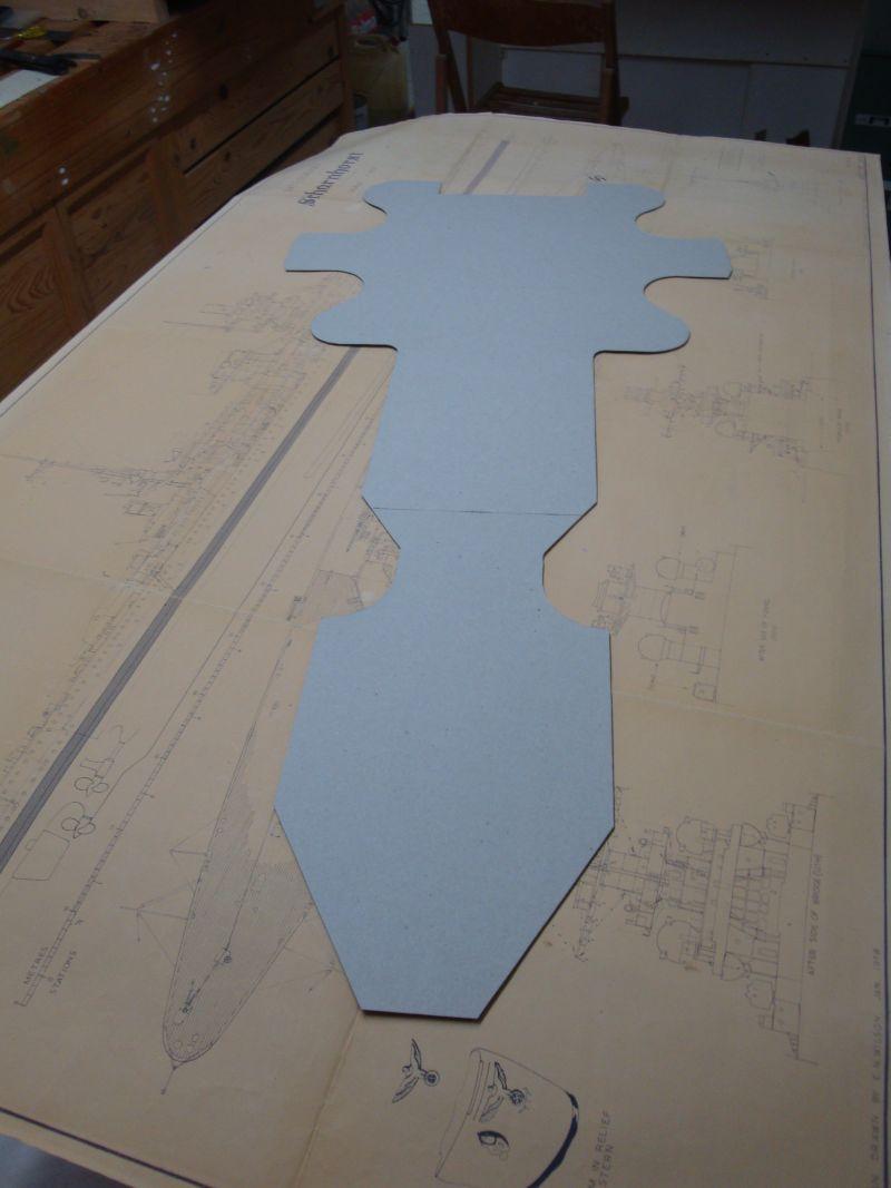
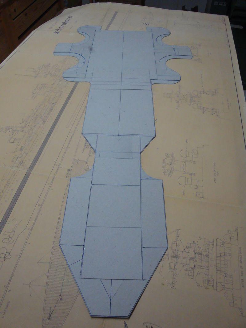
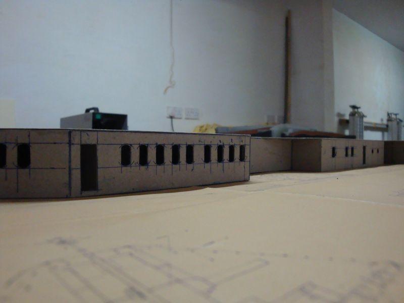
Good morning all, Thanks for looking in guys. Hi Foremast. The camouflage planned is the dazzle scheme she wore during the months of March to July 1943. Hi Larry - good to see you back. Hi Popeye - it's always a pleasure to read your posts. Today, I am posting the pictures related with the construction of the midship and aft superstructure. As always the construction is carried out with cardboard. Planning out the lines of the deck. Not an easy task at all, I had to apply some of the geometry, I learned at school. The deck, ready for the next step. A longitudinal view of the deck. A second layer is fitted on to the first layer. This is the guide for the superstructure outer skin walls. A closer look. A longitudinal view of the whole deck. A view from the underside, displaying the second layer. Fitting in the walls. Another view. Fitting in the reinforcing and stiffening supports. Please note the position and thickness. These are planned in such a manner to eliminate future material distortion and other mishaps, due to change in temperature and humidity. A close view, showing the thickness of the supports and the guiding strips, which aid in strengthening the whole assembly. The reinforcing well under way. A close view, displaying the number of cardboard laminations. These give enormous strength to the whole structure. A longitudinal view. The whole assembly nearing finish. The second part shall follow.

-
Good morning all, Thank you all for looking in, and for your support. Hello Foremast - no problem, I can answer your question, which is very valid indeed. Well - I was presented with a Heller produced 1:400 scale model kit of the Scharnhorst, on my sixth birthday. I cannot say that I did a good job on that. Being my very first model, and without any help, I tried my best. But the result was more than degradable. But for all intents and purposes, that was my first build and was proud of it. I used to spend hours playing around with it, and even had it's share of my bath tub. When I grew older, I seemed to develop a passion for three gunned turreted ships; and I can say that my favourites are the Yamato, Scharnhorst, Imperatrizia Maria, Viribus Unitis, Roma and Vittorio Veneto. At the age of 16, I enrolled with a scale modelling club, and obviously developed further my modelling skills, which finally gave way to the birth of the 1:72nd scale model of the Scharnhorst. After the Scharnhorst, I plan to build the German WW2 aircraft carrier - the Graf Zeppelin.
-
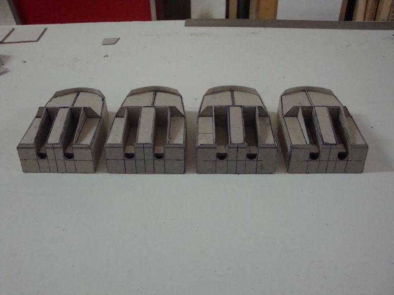
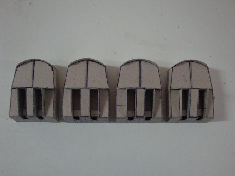
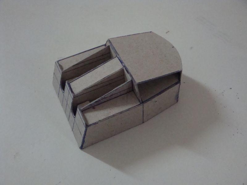
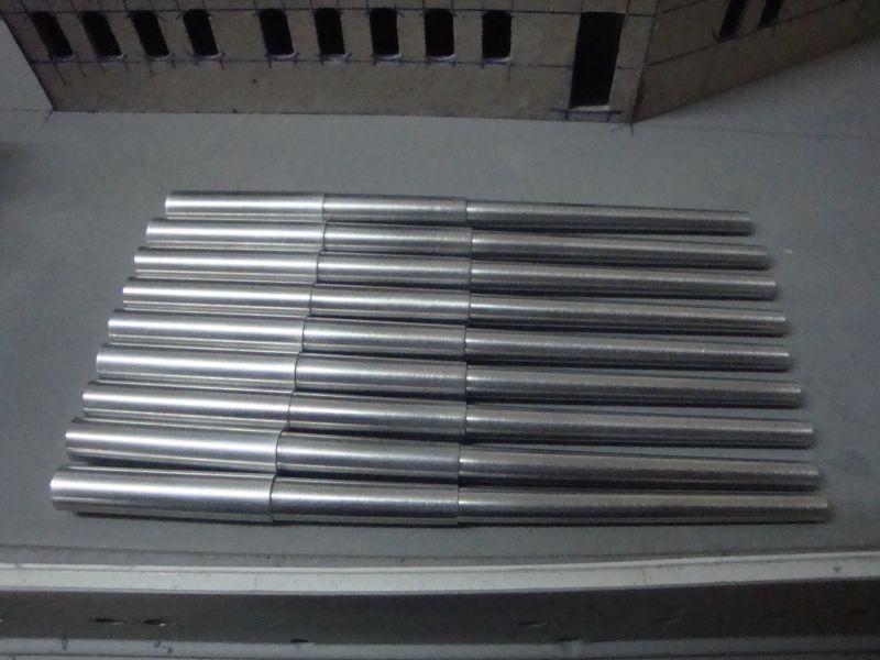
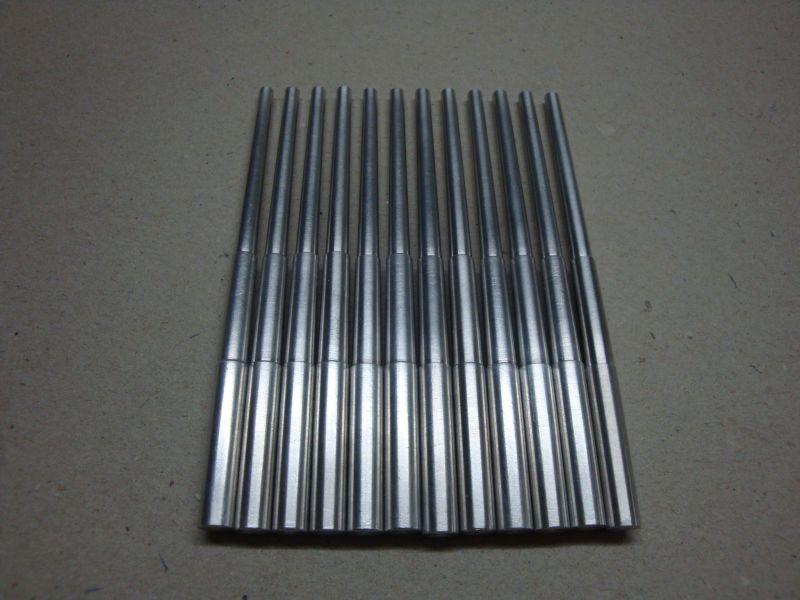
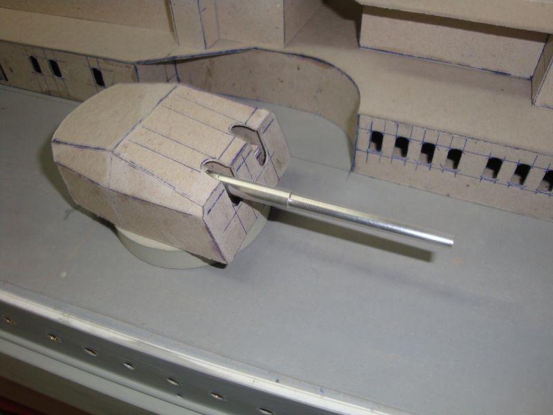
Hello all, The second part related with the costruction of the secondary turrets. Here goes. A view of the stiffener layer fitted at the rear part of the turret. Another view. A close up view. A front view of the four turrets. An elevational view. The start of the finish - laying the top skin at the rear of the turret. A view of the four turrets. Another view. A close up view of the front. A close up view from the rear Start off with the aluminium gun barrels. Another view of the works in progress. Note the marker tape. these mark each step size. Another view. The first gun barrel, ready for polishing. Nine barrels, three more to go. The twelve barrels required for the secondary armament are ready for detailing and finish. Inserting a barrel in place and checking for correct fitting. Now time for a cup of tea, and shall be posting more in due course.


-
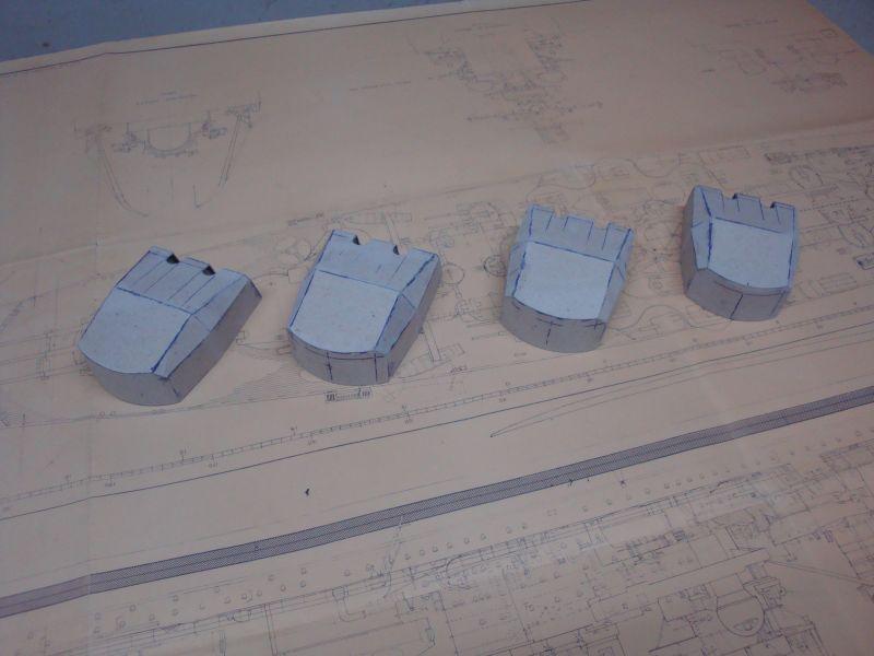
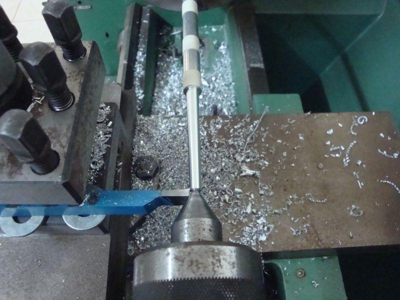
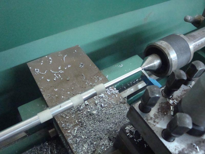
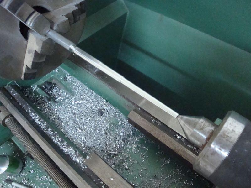
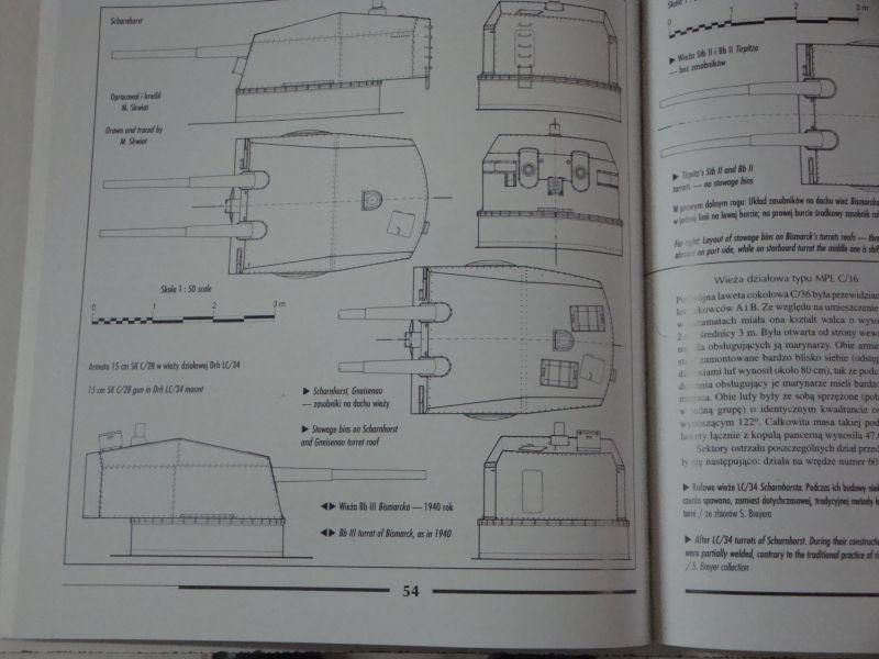
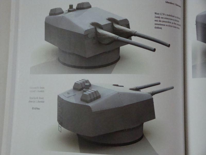
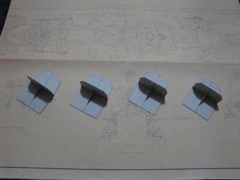
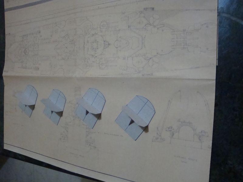
Good afternoon all, Brian, Peter, Joe, Anja - thanks for following my build and for the kind words. Just found some time to post more pictures. These pictures are related to the construction of the secondary armament turrets. As usual the main construction is carried out in 1mm thick cardboard, while the gun barrels are made from aluminium round bars and turned on my lathe. Here goes. The main font of information and research - The AJ-Press book - German Naval Artillery Volumes 1, 2, 3 & 4. A 3D view from the same book. The four bases, fo the secondary turrets. A top view, showing also the David Mc'Gregor scale plan of the Scharnhorst. The turrets well under way. The first turret, displaying the stiffeners and partition walls A view from the rear. Another rear view of the three turrets. A view of the stiffeners which are fitted between the partition walls. These give additional strength to the whole assembly, in order to allow the cardboard turret to bear the weight and the leverage of the aluminium gun barrels; without distortion. Another view. A front view. An elevational view. The four turrets, ready for the next step. A close up view. A close up view, showing the stiffener later fitted at the rear of the turret. Such stiffeners, will eliminate any distortion, especially during the months between winter and summer, and change in ambient humidity levels. The second part shall follow.
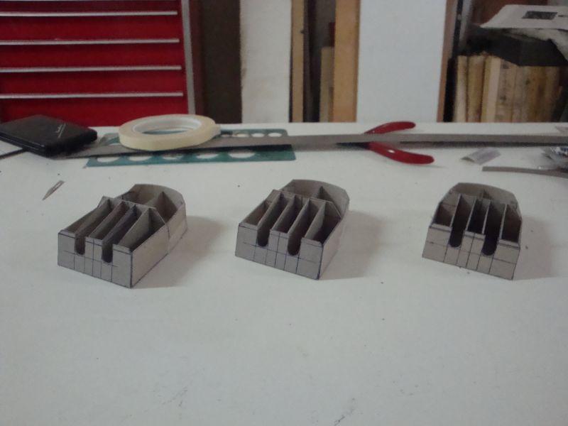
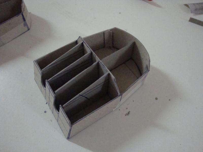
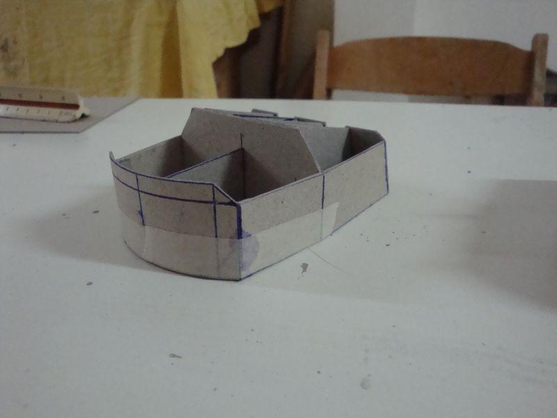
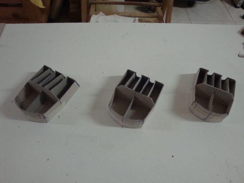

-
Wow, Fantastic work Popeye. Your scaling up is really good. Considering totally scratchbuilt and with wood, the planking turned out really well. Looks like that this shall be another of your masterpieces. Shall follow your build.