HOLIDAY DONATION DRIVE - SUPPORT MSW - DO YOUR PART TO KEEP THIS GREAT FORUM GOING! (Only 13 donations so far - C'mon guys!)
×


Paul Salomone
-
Posts
188 -
Joined
-
Last visited
Content Type
Profiles
Forums
Gallery
Events
Everything posted by Paul Salomone
-
 Hello Farbror, This would be a fantastic diorama to build. constructing a timber ship model is one thing, but to create a sunken vessel with damaged areas, is quite a challenge. Thumbs up mate - this shall be a good one.
 -
Good morning all, Hello Daniel, Ben, Banyan and Michael - Thanks for looking in. Banyan - Working Davits and falls - hmmmmmmmmmm - now that is a true challenge, when considering the small scale. But worth a try. You shall soon be owing me a point of good old beer my friend.
-
Hello all, Popeye & Brian, thanks for looking in. The ship's boats list consisted of the following: 1 - 3 x Motor work boats. 2 - 1 x Motor pinnace. 3 - 1 X Motor launch. 4 - 2 x 11 7 1/2 meter cutter. 5 - 2 x 8 meter cutter. 6 - 2 x 5 meter rowing boats. 7 - 1 x 3 meter rowing boat. 8 - 40 x cork and canvas dinghies. Yes, I would say that they will be a mini fleet within a fleet.
-
Hello Piet, I am very happy to hear that you are doing fine. As for the sub, don't worry, we all do our share of mistakes. We all leave something out, but at the end of the day, it's the end result that counts; and you are building a very fine lady - so keep it up my friend.
-
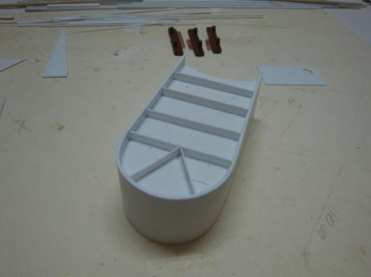
Good morning all, Hello to all those fine guys who looked in and left these gentle and kind words. Nobody can ever know what the future has in reserve for us, but I would think that it's worth to try to introduce this hobby to the young fellow or fella. This way, my wife will have two kids to take care of - me and the child. And the best thing about it, is that she will not grumble for spending too much time on modelling. At the moment the electrical panel assembly, is at a halt, as one of the members of the club (Oliver), who is a true expert in figures and AFV's, shall be giving me some lessons as how to weather the panels and creating highlights, using oil paints. I view of this, I embarked on another mission - the ship's boats. Here goes: The boats shall be made from styrene sheets, and covered with timber planks where needed. 1)- The main frame shall be made from 1.5mm thick styrene. 2)- The other frames shall be made from 0.75mm thick styrene. 3)- The covering shall be made from 0.5mm thick styrene. 4)- The boat's deck and working platform shall be covered with 3mm x 0.5mm thick light teak strips. The overall length of the motor work boat is 16cm. A good view of the boats - picture taken from the Kagero 3D book. A plan of the motor work boat in 1:72nd scale. The ship had three of these boats, so I have to prepare three main frames. The first main frame under way. Putting in the lining angles for the rest of the frames. The frames in place. A view from the rear. The front deck piece in place, together with the rest of the crew's working platform. A view showing the bottom. A linear view from the front.


-
Hello Alex, beautiful work my friend. Those guns have really added life to the vessel itself. Can't wait to see the start of the rigging.
-
Thanks grant, really appreciate your kind words
-
Getting better by the hour, Well done Piet - she is a beauty.
-
Hello Kevin, thanks for looking in. yes I would imagine that the Uk is suffering the heat as well. here in Malta the humidity is sky high, and mostly unbearable. The ac units in both the bedroom and the kitchen area, are working out full blast. At the moment, I have to suffer the heat in my workshop, as all our funds are tied up, as we are going through a child adoption process - who knows, perhaps a future ship modeller. But later on, I have already told the shop steward (my wife), that we shall be installing a VRV air-conditioning system to feed all the rooms of the house, including my workshop of course.
-
Hello Greg, Thank for the kind interest, and your encouraging words.
-
Thanks Brian.
-
Good morning to you all ship modelling friends, It's flippin hot here in Malta - over 35 degrees C - I always said that winter is the best season of them all. Some more updates related to the range finder platform and the admiral's bridge. Here goes: The small range finder nearing it's completion. A view from the front. The foot rails. Another view. A side view of the foot rails. Storage cabinets to be mounted just behind the range finder housing. Starting off with the voice tubes. The first one is well under way. Note the copper wire. This is to simulate the flexible tubing, which covers nearly all the length of the voice tube. The set of four are ready for the next step. The four voice tubes, together with the first set of cables required for the admiral's bridge electrical panels. Starting off with the finishing of the electrical panels. The first set of cables, set in place. A close up view - a bit blurred - sorry, my camera is not that sophisticated. Shall be posting more pictures next week.


-
Hello Mark, Finally, I found some time to start browsing some logs. First of all - WELL DONE - nice piece of timber work indeed. As I always say, I am not into period vessels. I once started off with the Billing's Wasa, and stopped half way through, as I would like to detail the interior. But I can surely recognise good work, and you Mark, are a master in the making. Secondly, I wish you a delayed Happy Birthday, and many happy returns and lots of ship modelling sessions.
-
Hello Popeye, Looks like that you have to give out some increase in salaries to get the Half Moon ready for launching, or are the workers employed on the other build? Just joking Popeye, great job as always. I am quite sure that this will be another masterpiece to add to your collection.
-
Hello Popeye, I haven't browsed your build log for quite some time now, as I barely find enough time to insert mine. Wow - now that is some fine rigging mate - keep it up, you are doing a fine job.
-
Hello Sjors, I follow you in silence as well - well good work indeed.
-
Hello Foremast, I am doing a bit of catching up, and browsed your log. What you describe as an error or mistake, isn't noticeable. All that I can see is a very beautiful vessel of the period, which I am quite sure that everybody agrees to the fact that you have built a masterpiece to be proud of. Well Done.
-
Hello Piet, Superb woodwork and finish. Just cannot wait to see it ready.
-
Wow, can I have a piece of that land pleaseeeeeeeeee?
-
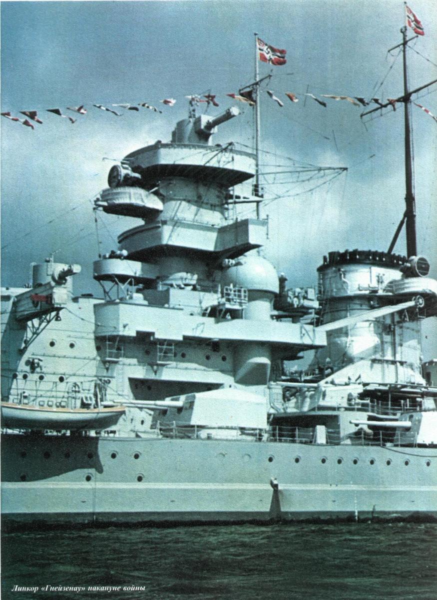
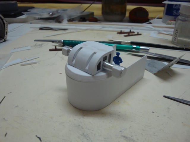
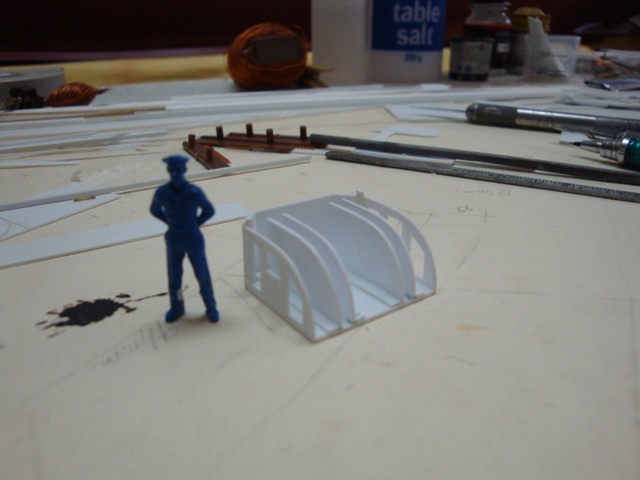
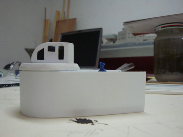
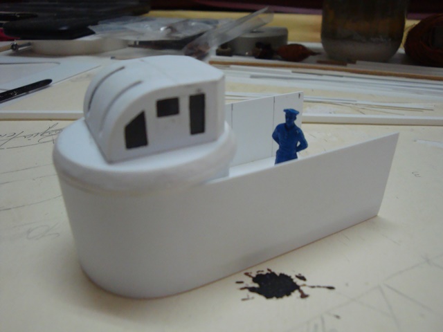
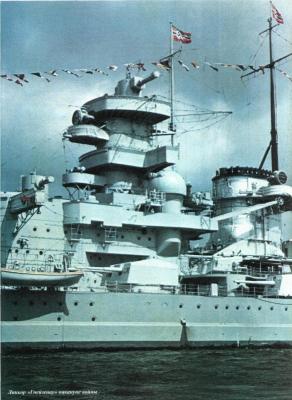
Hello Brian and Mark, thanks for looking in. Mark - to answer your question, yes the access door is a bit too small. Even the access to the platform was not easy, as there was no access, leading from the armoured tower to the platform itself. The men posted to man the range finder, could only climb up to the platform, via a ladder located on both sides of the platform. From what I read, the range finder was manned by only two persons. One was seated exactly in the centre of the range finder, and the other was seated near the window. A bit cramped, but the Scharnhorst was built for one purpose - to go to war. The purpose for the range finder was to direct the forward anti-aircraft guns. Of course, these were aided by the domed 2mtr range finders located at the sides of the ship. The access door had to be smallish, as the housing was constructed after the installation of the range finder. This being after handover to the Kriegsmarine; and the revealing of some setbacks endured during heavy seas. So the builders had to dimension the housing according to the rangefinder, already installed. Further more, the housing was added to shelter the crew, from the heavy seas and icy cold temperatures, whilst also offering a degree of protection during battle. Below is a copy of an original photo in colour of the Scharnhorst in her early days. Note also the Admiral's bridge was of the open type. This was closed off during the early winters, when it was clearly seen that the bridge had to be of the closed type.
-
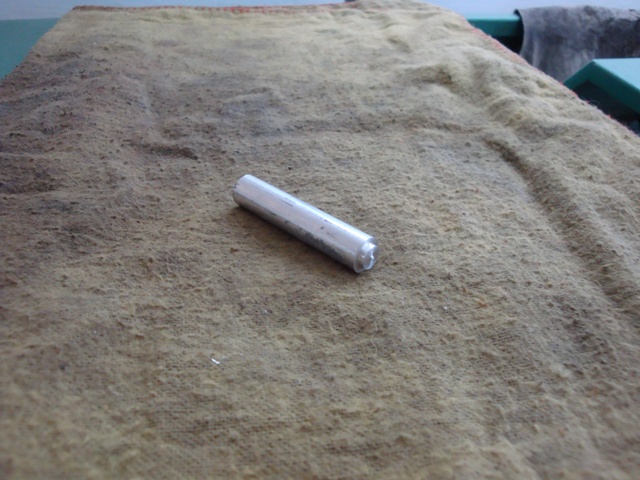
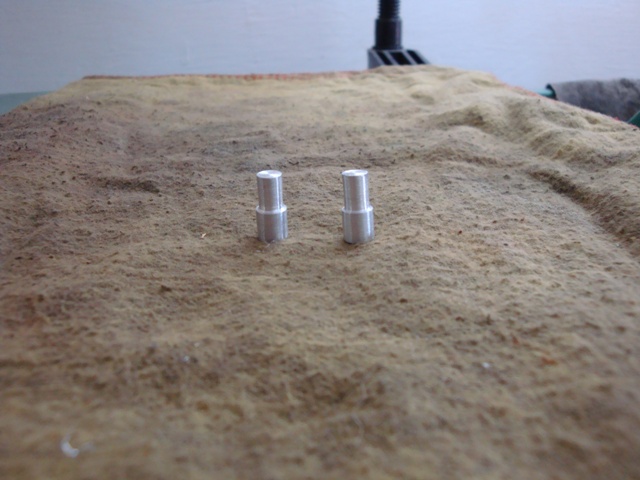
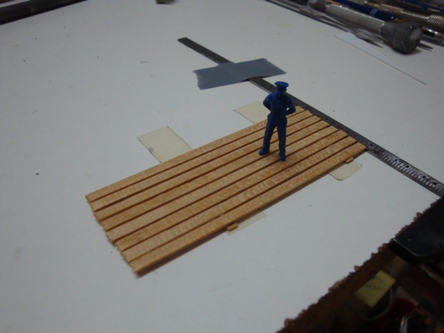
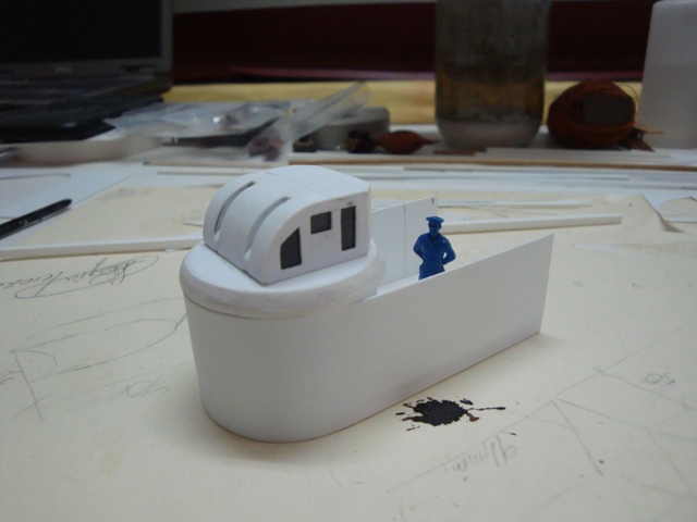
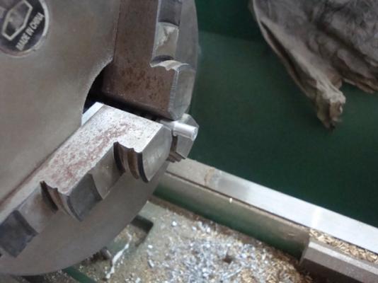
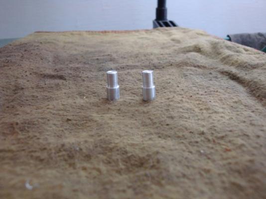
Good morning all, Please excuse my long absence, work before play, as they say. Found some time to put in some more work on the 2mtr range finder. Hello Kevin, GJDale, Michel, Larry and Wackowolf. Thanks for looking in and for your never ending encouraging words. I think it would be wonderful if we all lived in the same town. Some progress pics, here goes: A close view of the range finder mounting. A 10mm diameter aluminium rod, required to produce the range finder arms. Finishing off the first arm. The two range finder arms, ready for the next step. The range finder arms, fitted in place. The access door, located at the rear of the mounting. A view of the progress so far. Starting off with the timber flooring. Now that things are moving along, I think that I shall be able to post more pictures during this week. Cheers


-
Thank you Adrieke.
-
Thank you Brian.
-
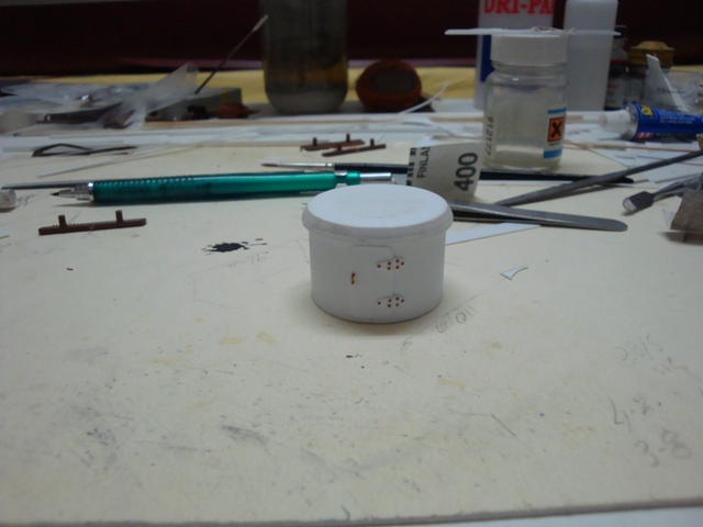
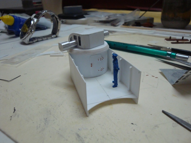
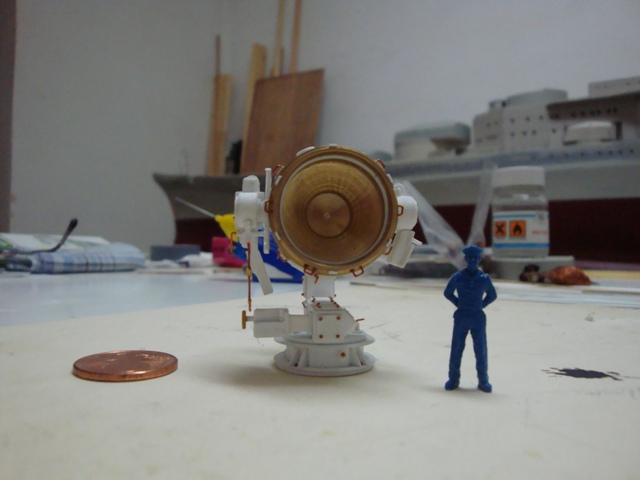
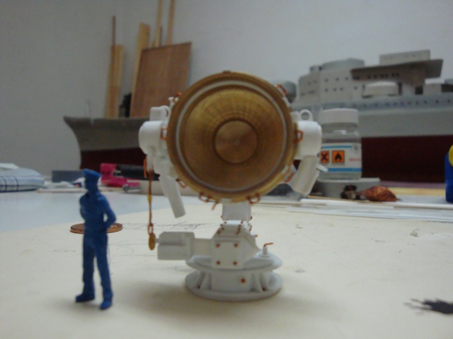
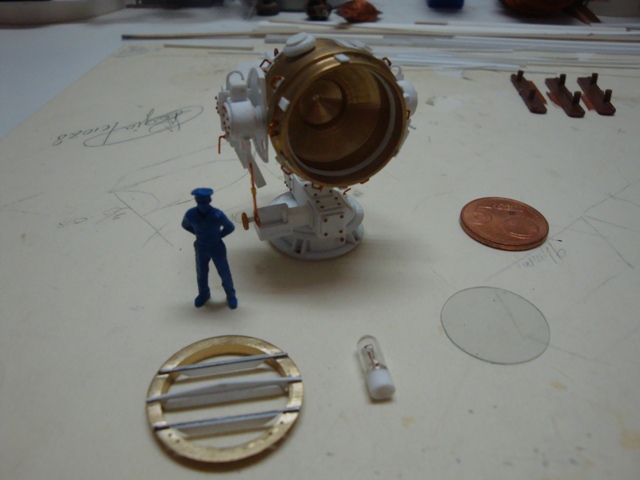
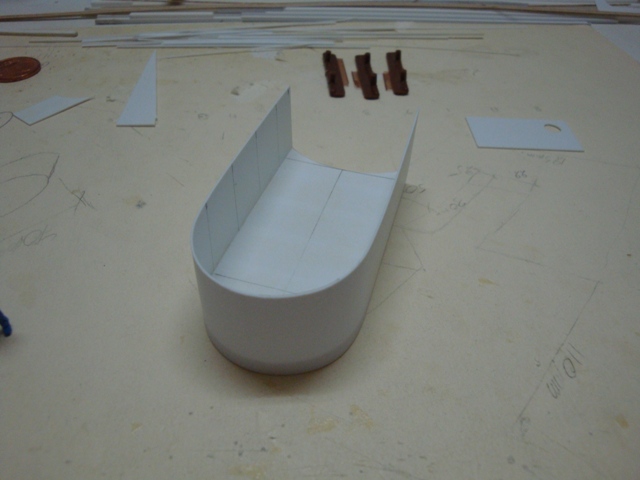
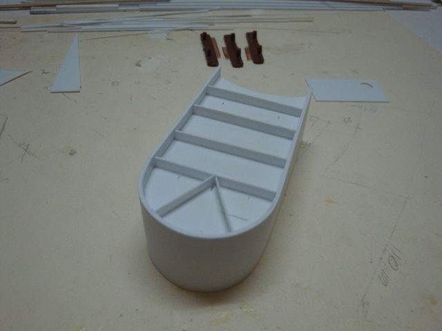
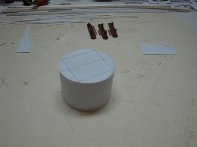
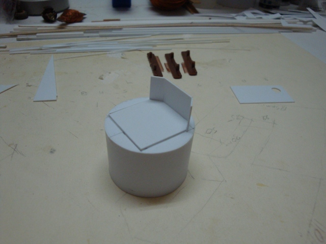
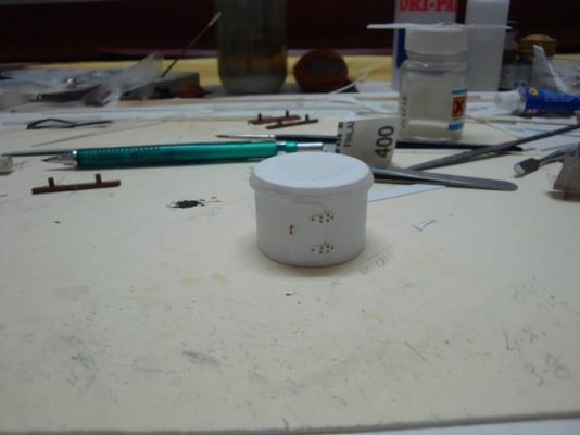
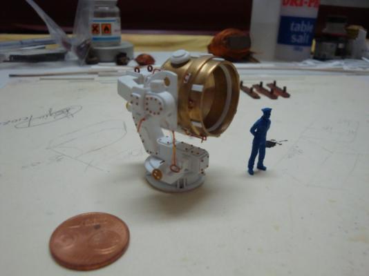
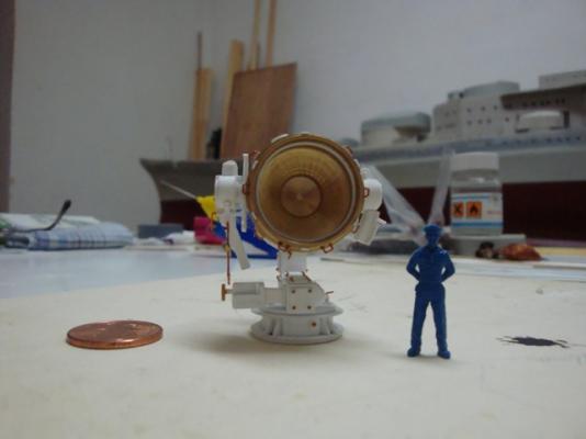
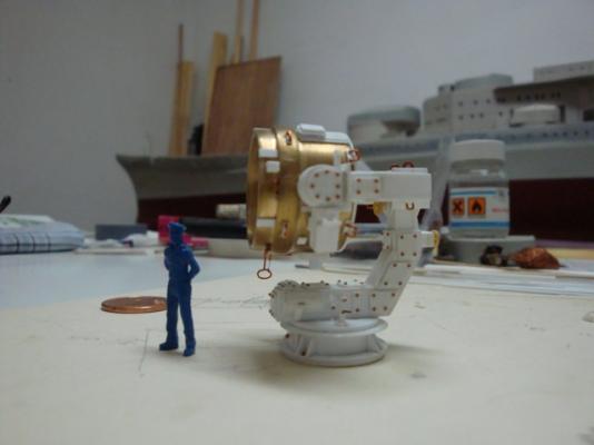
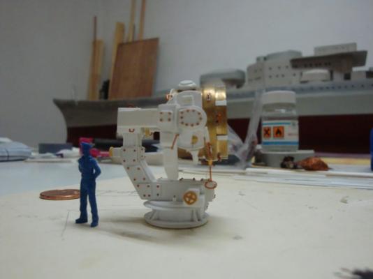
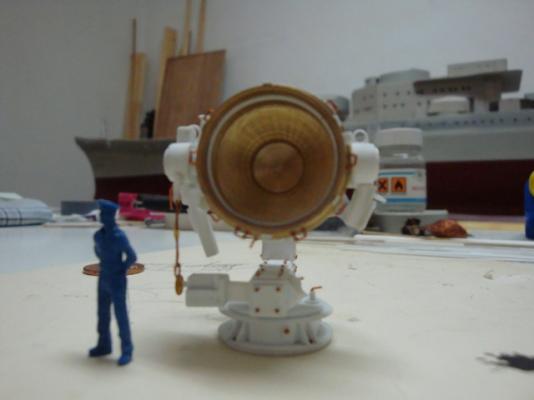
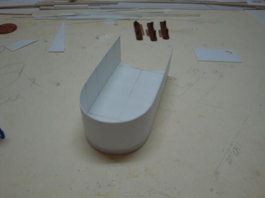
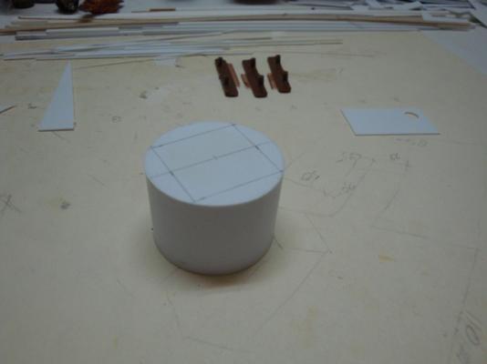
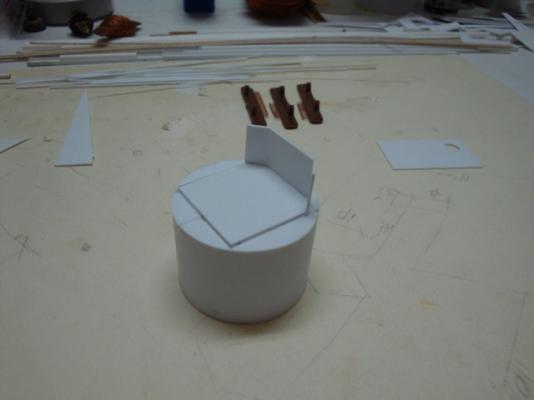
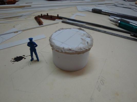
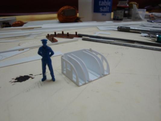
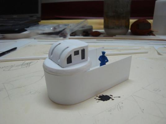
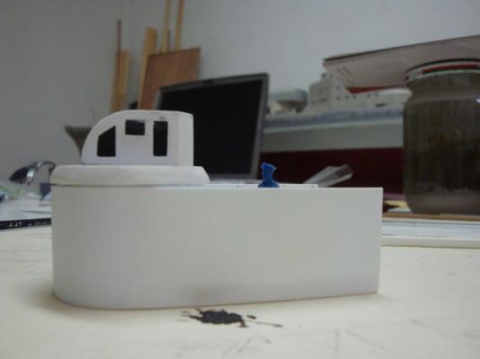
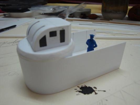
Good morning all, Hello Popeye and Michael, Many thanks for looking in and for your kind compliments. Today, I am going to post the last pictures related to the construction of the search light installation, as it is now awaiting the right moment for the finishing stages. Here goes: An overall view showing the detail and the bolt heads. A front view. A view from the side. A view from the other side. A close up view. An elevational view, displaying all the other parts, to be fixed in place during the finishing process. Now some pictures related to the last range finder making part of the tower. This is a 2 meter long range finder, and is situated just below the Admiral's bridge. The platform with it's sheet steel parapet wall. A view from the under side showing all support struts. The armoured base housing, on which the range finder sits. Starting off with the housing. Applying filler to create the taper edge.. The range finder housing well under way. The assembly ready for the next stage - detailing. A side view. A close up view. shall be posting more pictures next week.

-
Hello Sherry, Some very good progress indeed. I fully agree with Mark - The use of a cannon, will help a lot; especially when finishing the aperture to the correct size and height. For example, I always keep a figure handy, so that when dimensions on both the scale plans and books don't make sense, I double check.