HOLIDAY DONATION DRIVE - SUPPORT MSW - DO YOUR PART TO KEEP THIS GREAT FORUM GOING! (Only 13 donations so far - C'mon guys!)
×


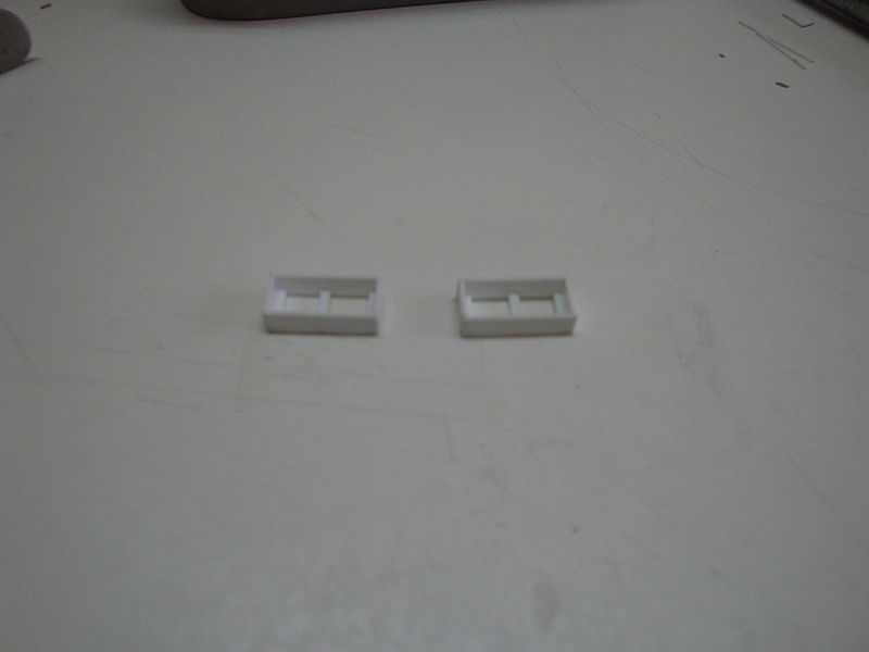
Paul Salomone
-
Posts
188 -
Joined
-
Last visited
Content Type
Profiles
Forums
Gallery
Events
Everything posted by Paul Salomone
-
 Hello Alex I quite agree with you. The bear represents a symbol of power and determination for the German states at that time. Hello Kevin Yes, I feel a bit pressed under heavy weights, from all sides. Even the club members want to see more detail. Poor me.
 -
Hello Popeye, thanks my friend, your build is quite a sight as well. Hello Wacko Joe, I'm afraid that yes, you will have to wait until Monday. It's the detailing that envelopes quite a huge amount of time. How about coming over to Malta for a holiday? I try my best to put all the work and bits on the forum, but sometimes I only remember to take photos when the thing is ready. Even so, with the secstant - it's so small that even if I had to take a photograph of each bit, nobody would understand a thing. I mean, it is impossible to take a decent photo of 1mm or 2mm long bits. See you all next Monday.
-
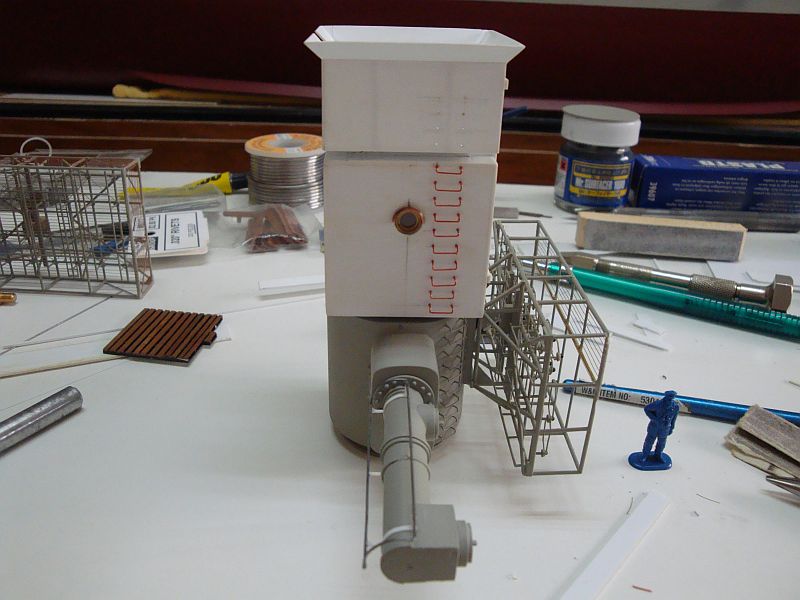
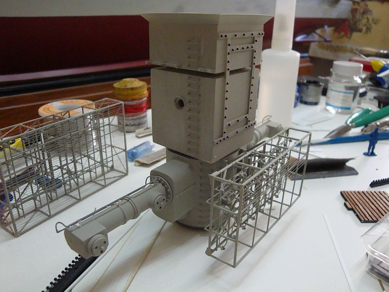
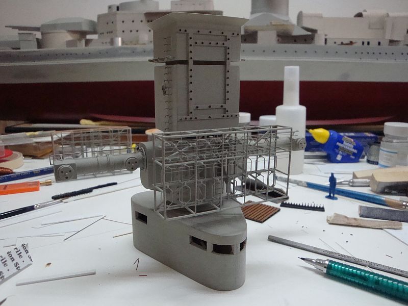
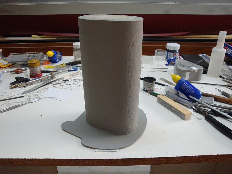
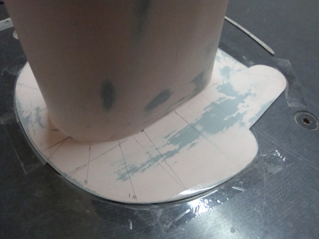
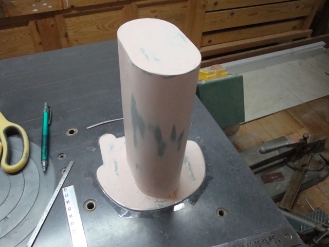
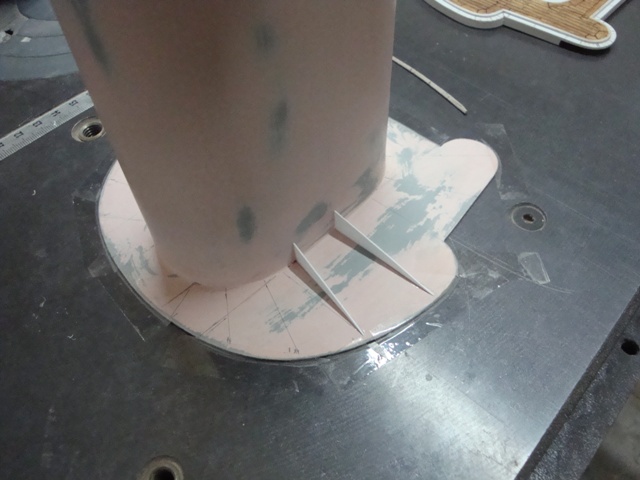
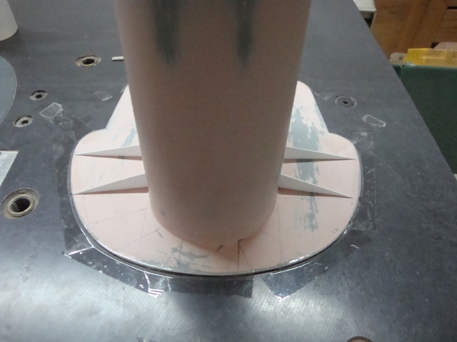
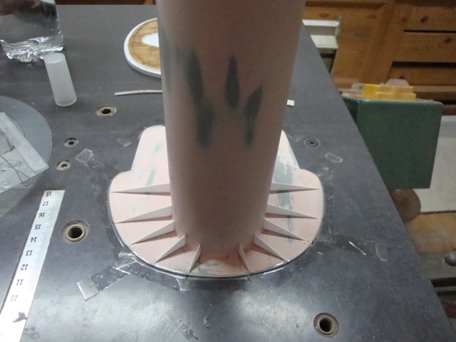
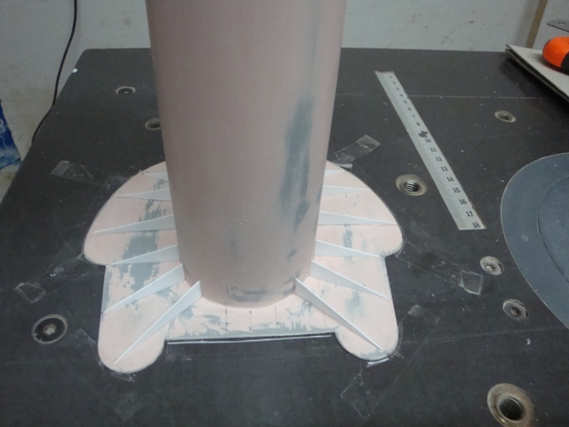
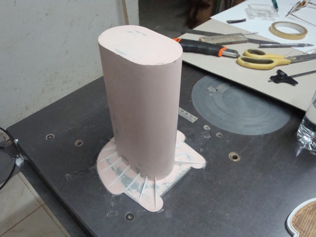
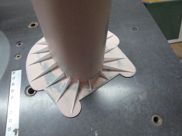
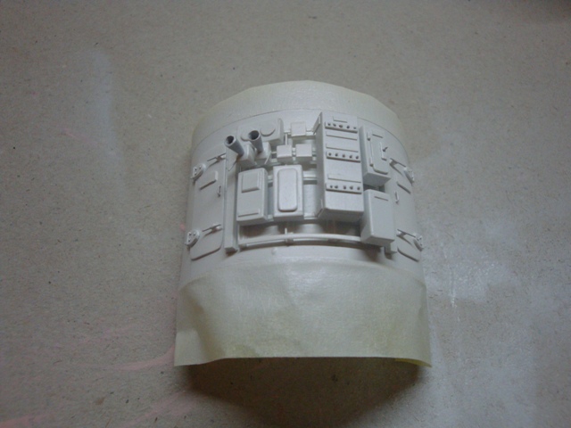
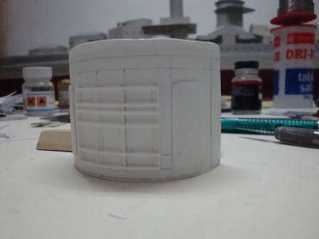
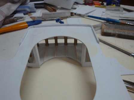
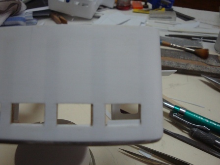
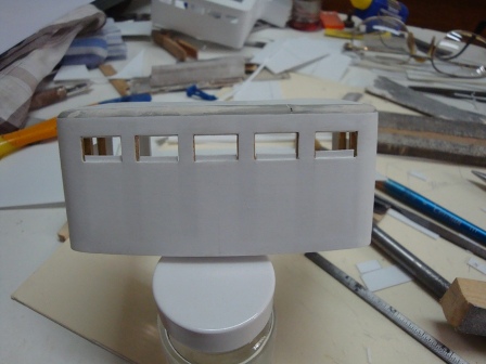
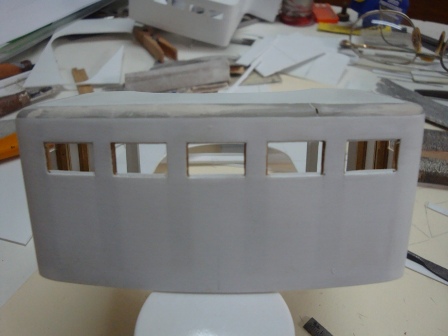
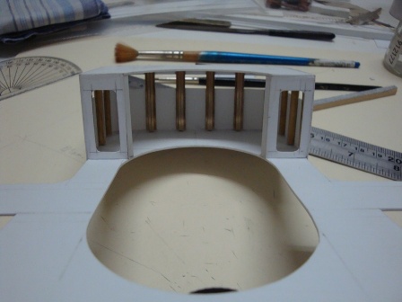
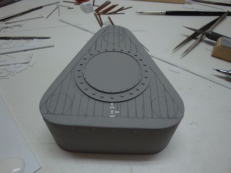
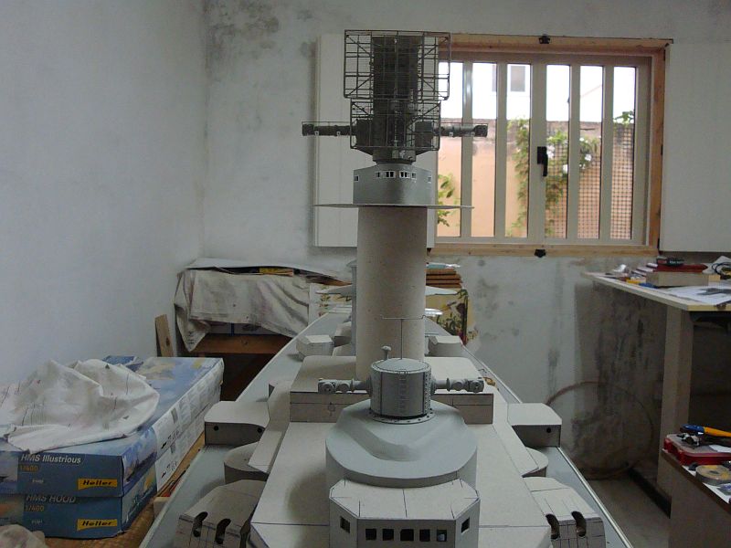
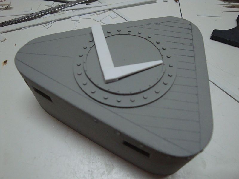
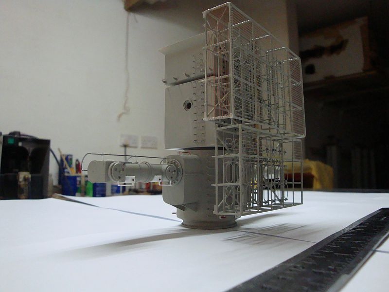
Hi Guys, Some progress pics related to the progress made so far on the ships armoured tower. Here goes. The tower, literally bathed in grey primer paint. The marking out for the balcony support struts. Sorry about the pink undercoat. Marking out ready. Unfortunately some of the lines are invisible. The first two struts. A view from the front, showing the struts on either side. The front side of the tower is ready. Finishing off the rear side. An elevational view. The job is over and done with. All the struts are in place. Will be posting more progress pics on Monday. Have a nice weekend.
-
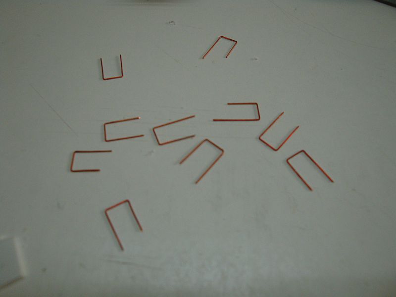
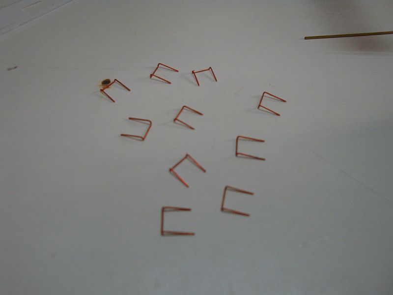
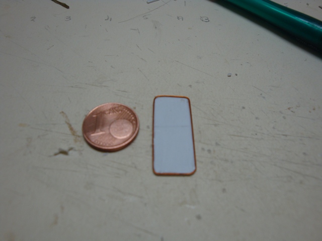
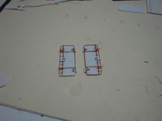
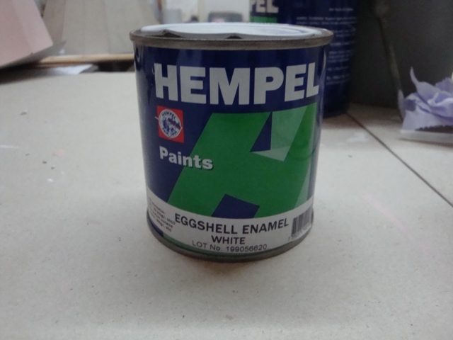
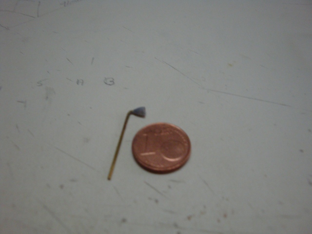
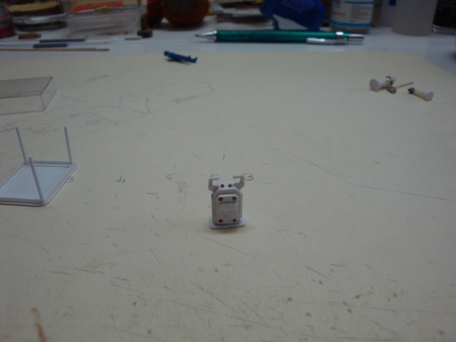
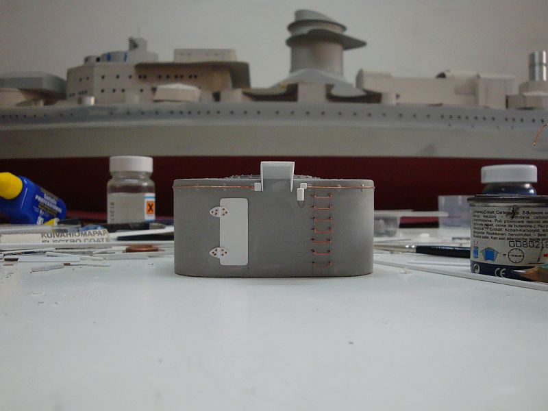
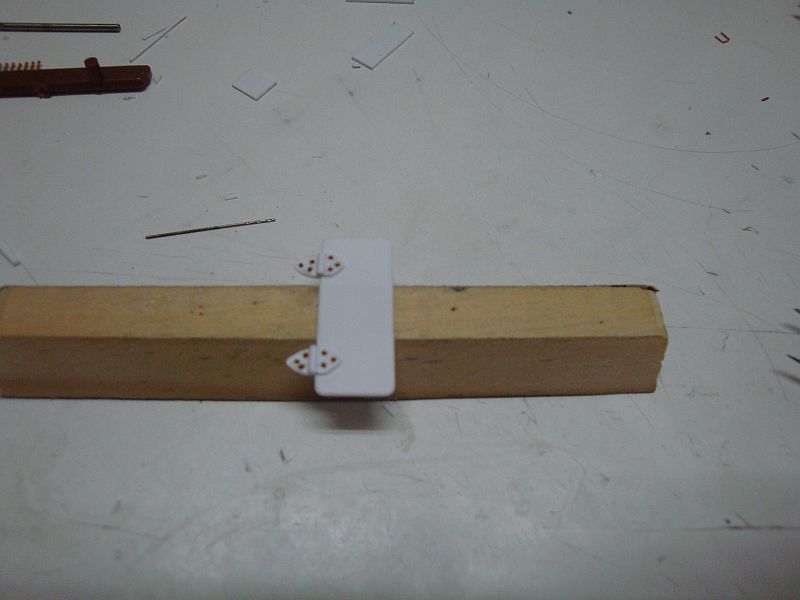
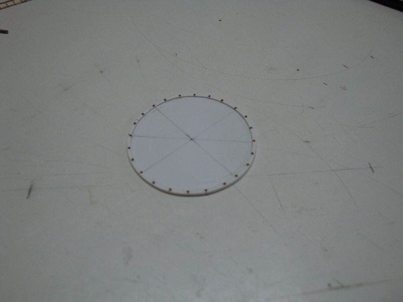
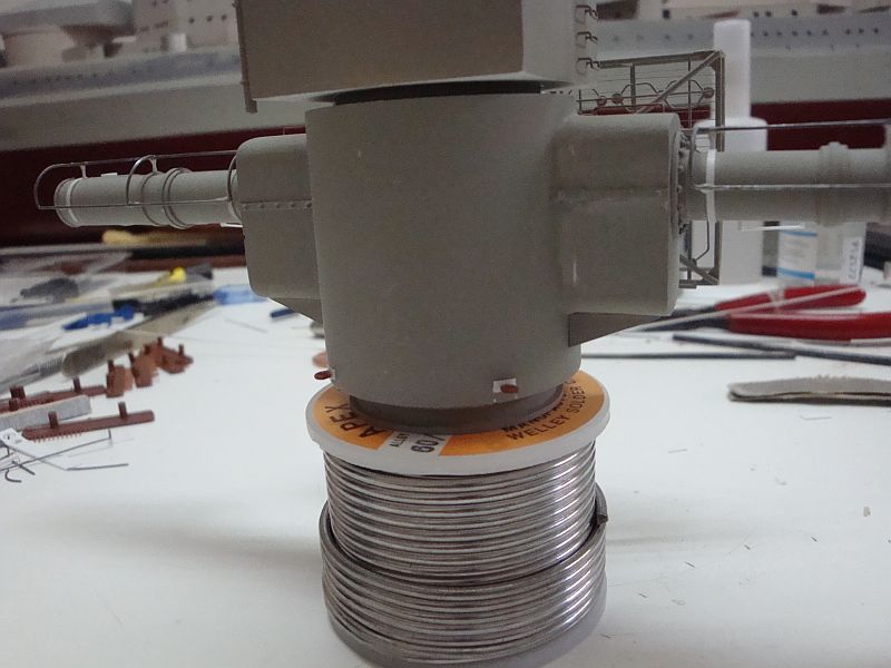
Good morning all, Hi Popeye - always a pleasure hearing from you. Some pictures related to the construction of the admiral's bridge. Here goes. Starting off with the bridge access doors. The rim edge using copper wire. Adding the details. Both doors ready for finishing. The ship's secstant and the supporting pillar. This tiny thing is made up from 28 pieces. Tried to get another shot, but the thing is so small that the camera lens could not focus better. Coating in eggshell white. The rear panel and equipment in eggshell white. The interior of the bridge in eggshell white. The paint used - Hempel Marine Paints.

-
Hello Pat, Just one thing on the ship's cat. The Germans had a tradition of keeping a small bear as the ship's pet. There are photos of such animals on board the K-class cruisers and the Hipper. On the contrary, the U-boat crews raised small piglets as pets and a good meal, when the food ran out. I never read anything about pets on the Scharnhorst though. A small pet would make a very nice addition to the detailing. The Germans were quite hygienic persons, I wouldn't imagine a lot of rats on board their ships.
-
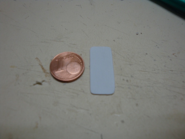
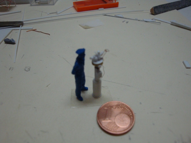
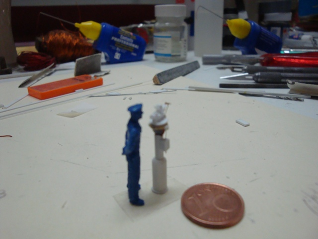
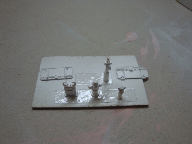
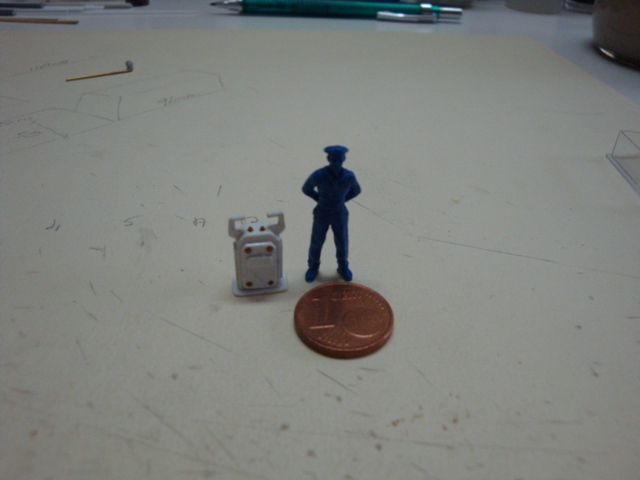
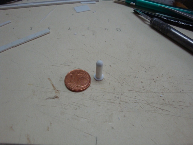
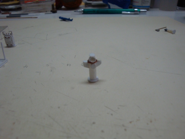
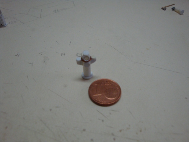
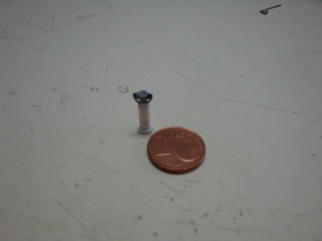
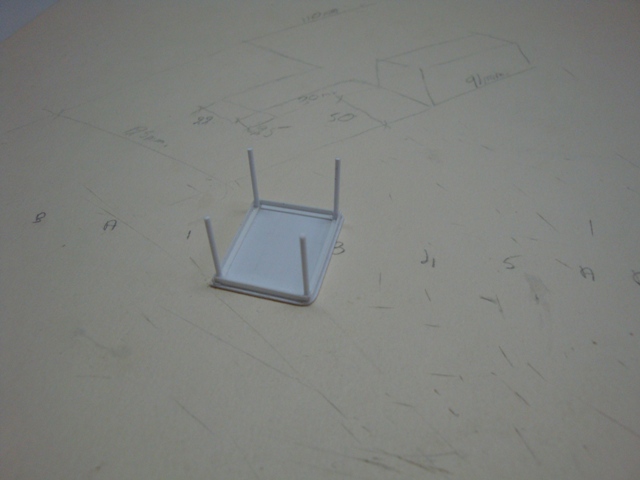
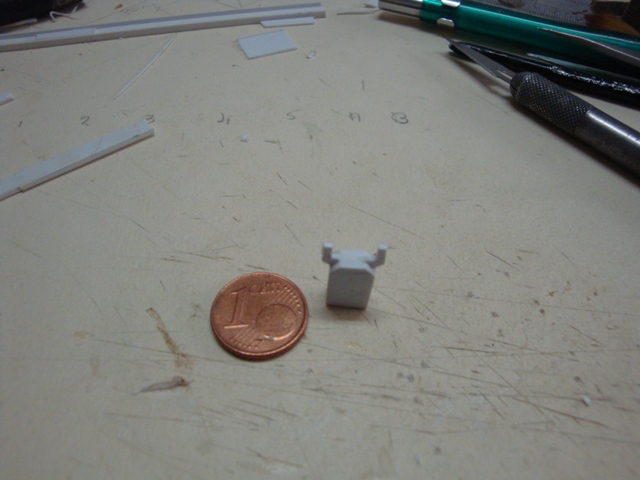
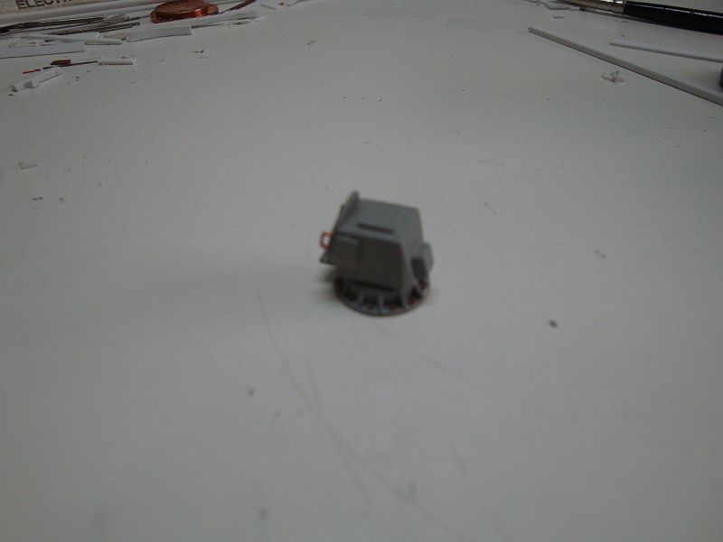
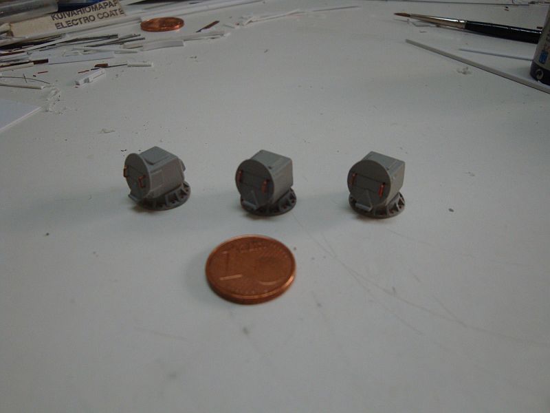
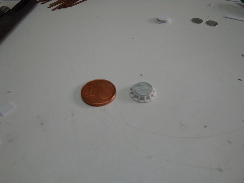
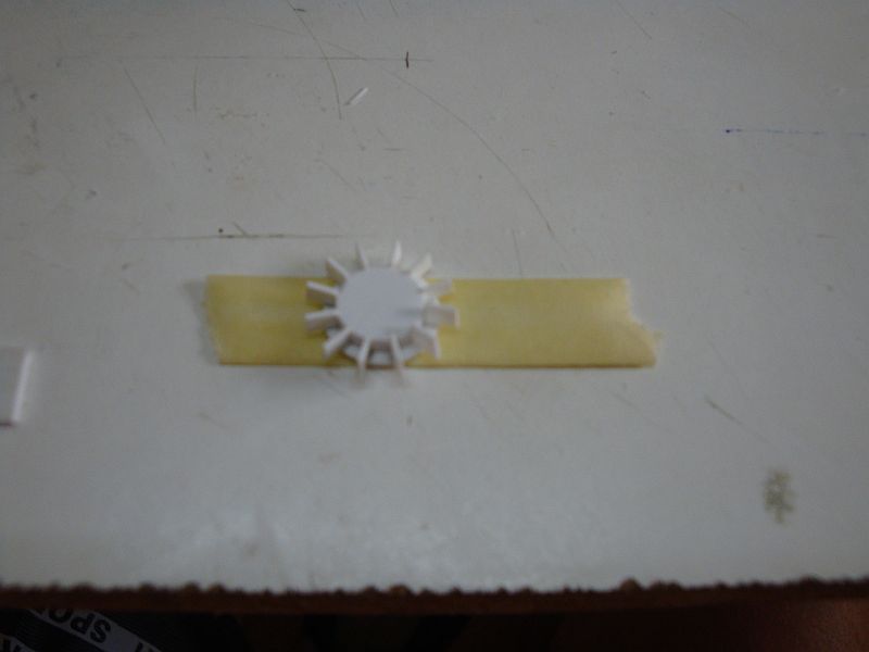
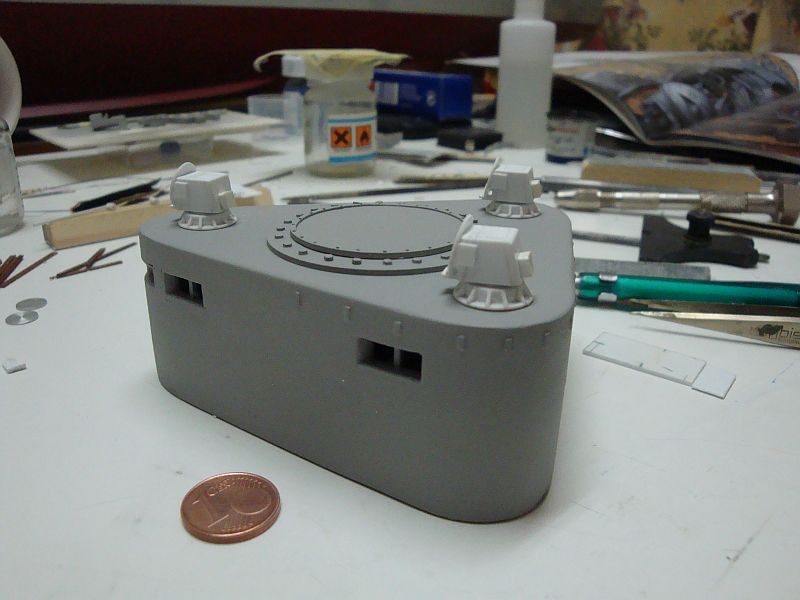
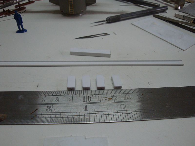
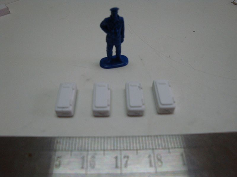
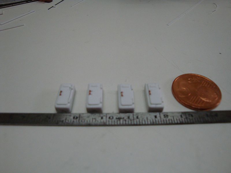
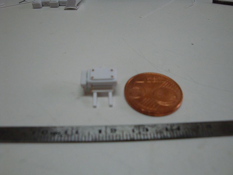
Good morning all, Hi Augie, Daniel, Ben Pat and Doug, thanks for looking in and your gentle comments. Today I am posting more pictures related to the construction of the admiral's bridge. Here goes, The steering module, adjacent to a 1:72nd scale figure. Starting off with the ship's compass. The compass nearly ready. The compass in comparison with a small Euro coin. The voice tube, which was situated in front of the helmsman. The gyro-compass. The chart table under construction. The chart table ready for finishing. The chart table's final resting place when ready. Not much more pictures now to post. Tomorrow, I shall post the last set of pics, which represent the progress made so far.

-
Hello Sjors, Haven't browsed your log for quite some time now. My God, Now that is a very elegant looking ship you have there. Keep up the good work, and be careful with the masts and rigging. Don't rush things, as the rigging dresses up the whole vessel. Will keep on watching this log for sure.
-
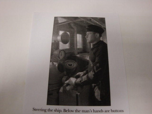
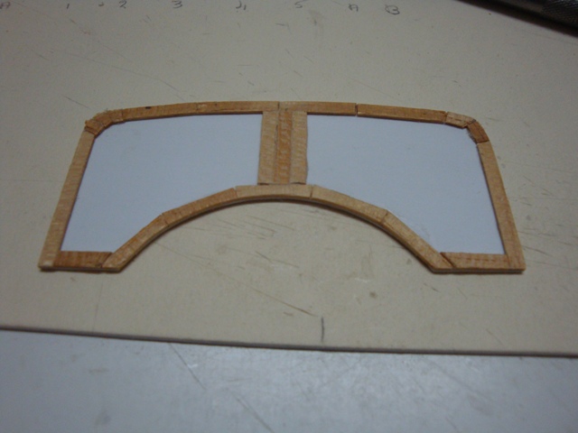
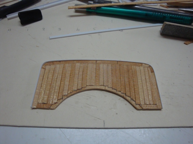
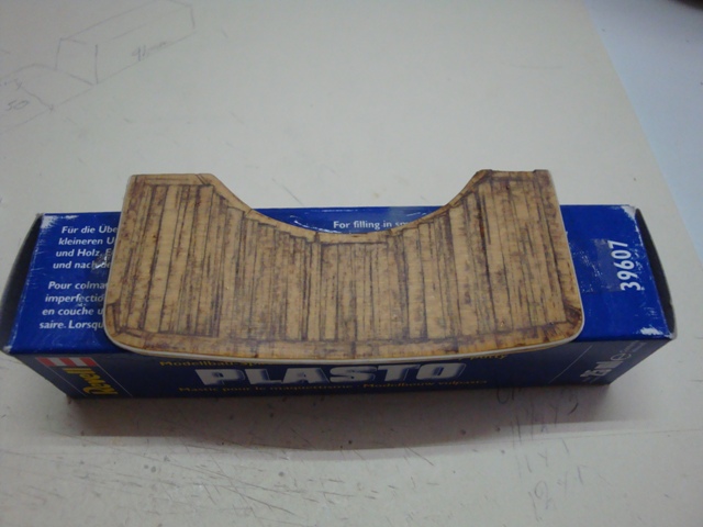
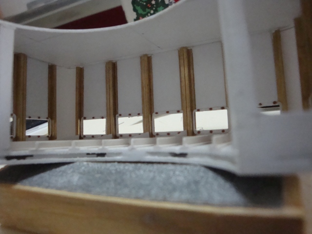
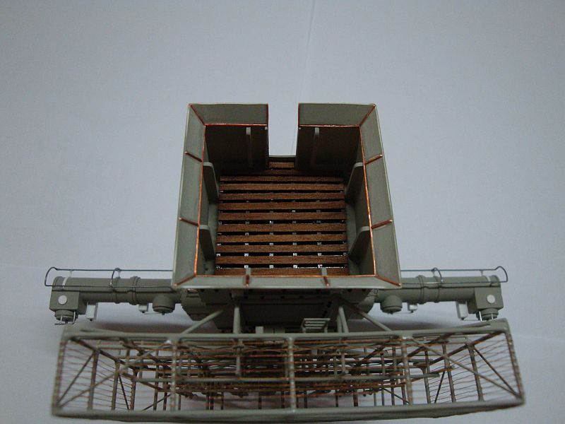
Hello my friends, Got some more spare time, So I am going to post some more pictures. Here goes, A very rare photo of the Scharnhorst's bridge, showing clearly the advanced technology and rudder steering gear. The pictures shows, the rudder steering module, the ship's compass, the rudder indicator gauge and the gyro-compass. A voice tube can also be seen together with a rain water drain pipe, which drains water from the search light platform, situated, just on top of the bridge. Starting off with the floor planking. Just remember that the bridge was just an open balcony in 1939, the admiral's bridge was added later on. The planking ready for the finishing. Applying the coats and washes. The floor planking is ready to be fitted in the bridge. Fitting the stiffeners. A close up view. The central air heating pipework. The steering module. The steering module ready for the finishing. Will post more pictures next Wednesday.
-
Hello all, Kevin, Patrick and Michael - thanks for looking in and for the kind words. Patrick - books and plans help me quite a lot, but the information, I needed to accommodate the detailing in hidden areas such as the bridge; was very difficult to get. I spent hours and hours, browsing the internet for any photos or pictures, which suit my needs, and sometimes I am lucky to get some information from other forums as well, especially German based forums. Some time ago, I got to know a very helpful guy from Germany - Stefan. He was able to send me a copy of some plans related to the interior of the aircraft hanger. With these in hand, I will be able to detail the interior of the hanger, construct the aircraft lifting cradle; together with the two Arado 196 Seaplanes, which were stored in the hanger with their folded wings. Sometimes my friends - things get so difficult, that nasty thoughts rush through my mind and give up. But the truth is that I just fell in love with my build, and that gives me all the strength I need to get her ready for the launching. Your kind interest of course, helps a lot as well.
-
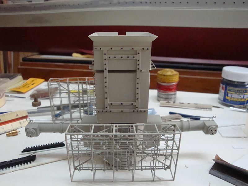
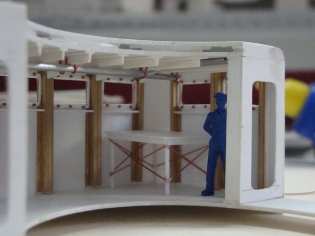
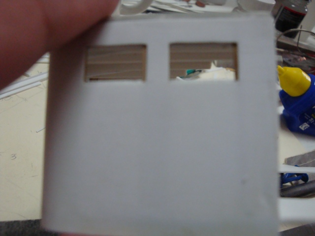
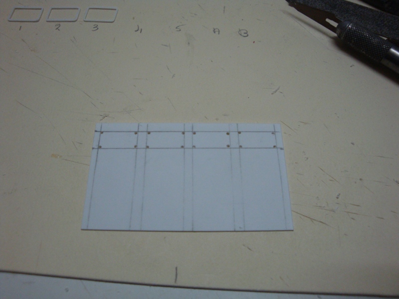
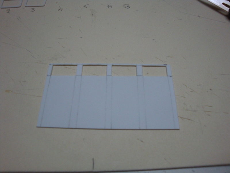
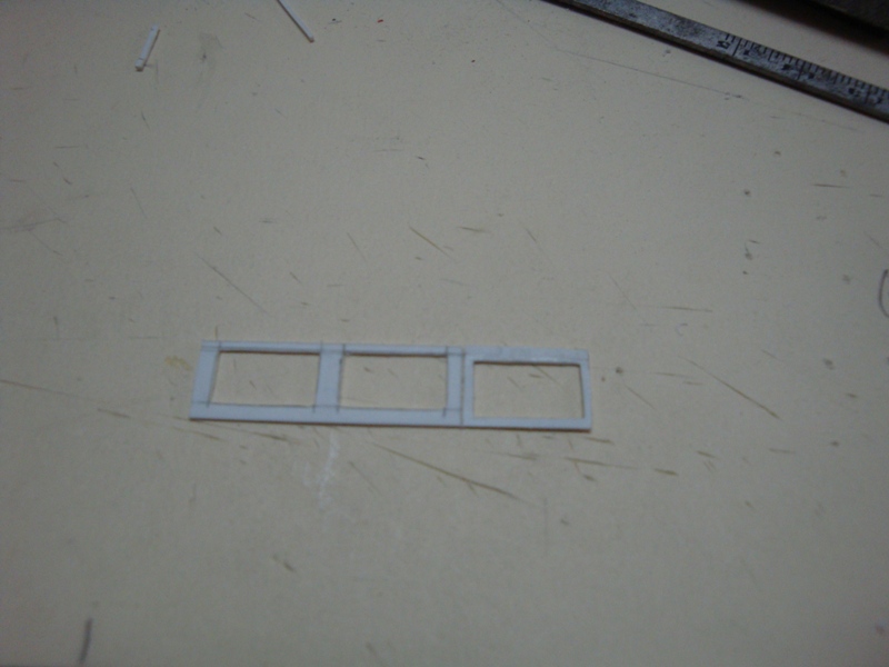
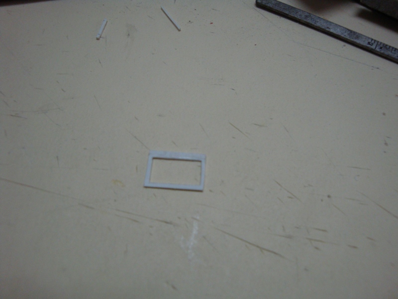
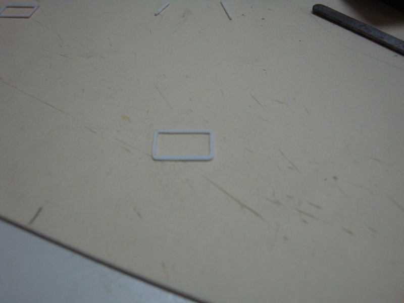
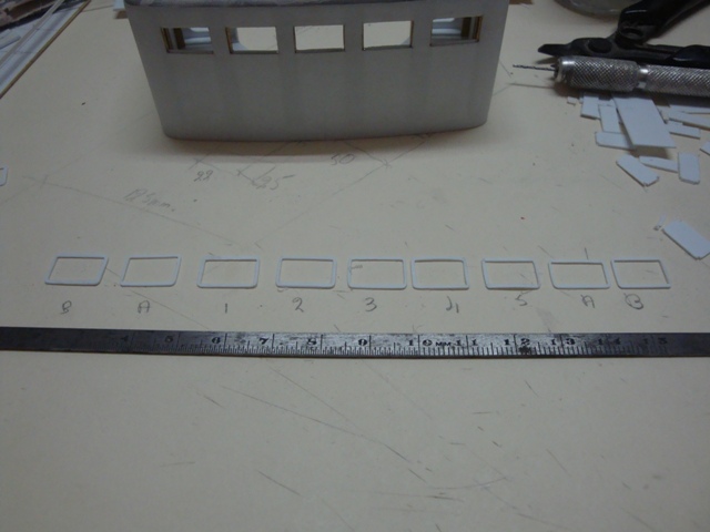
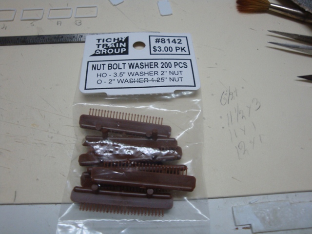
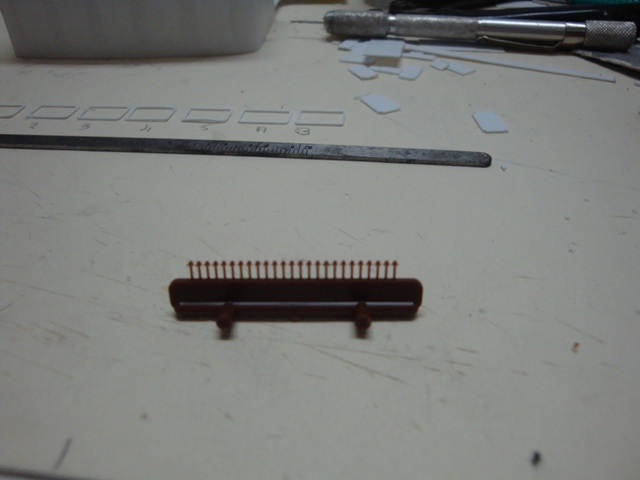
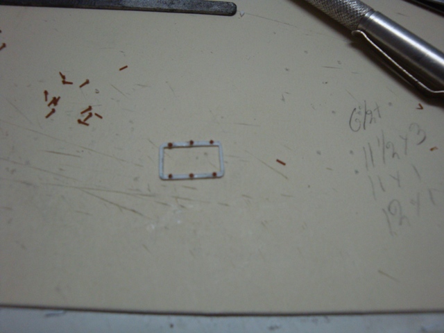
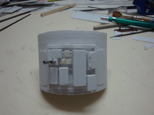
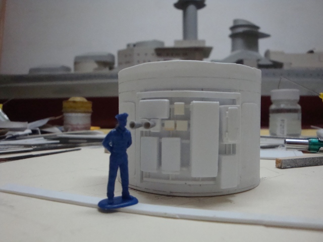
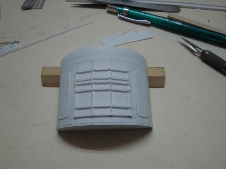
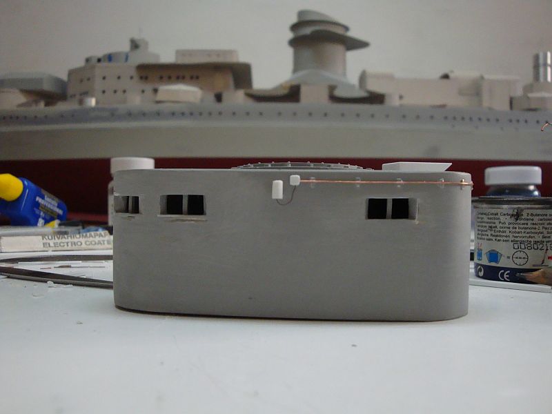
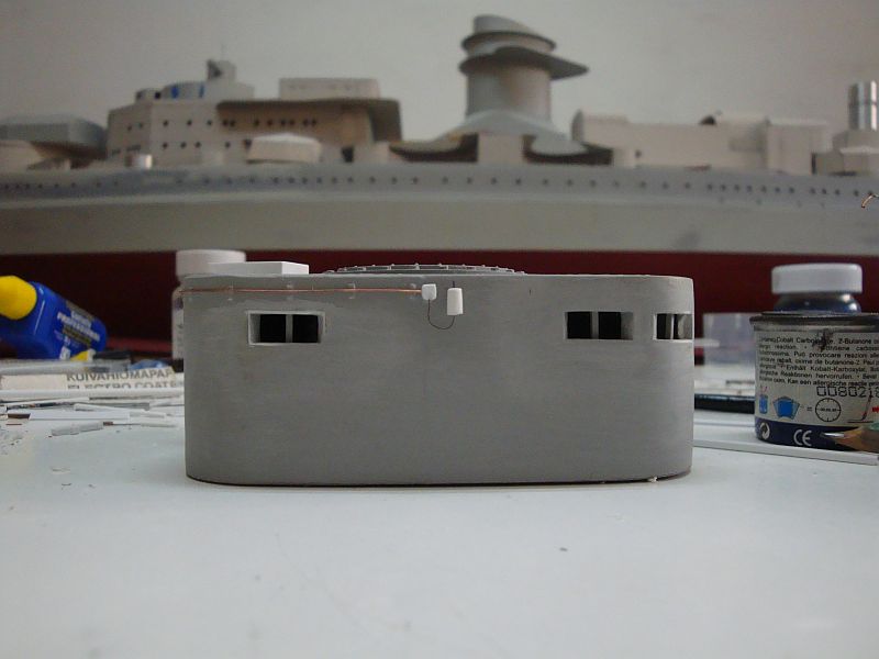
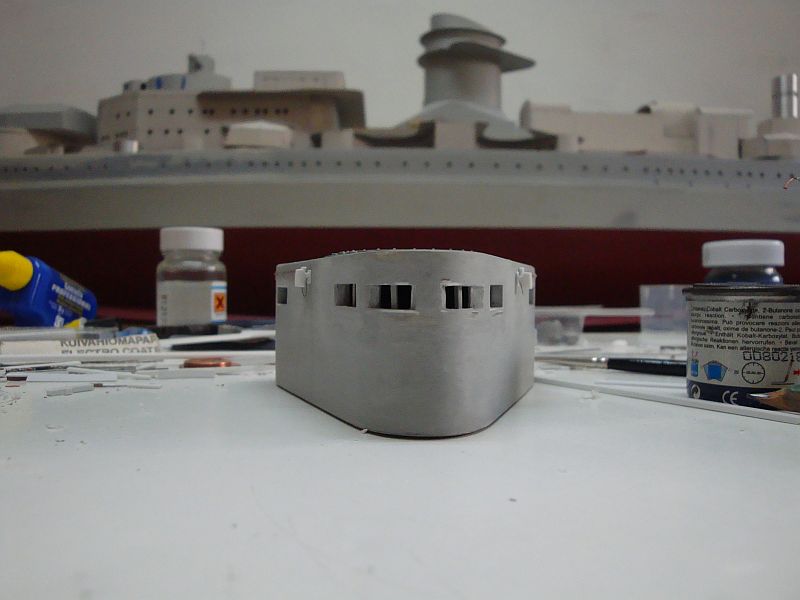
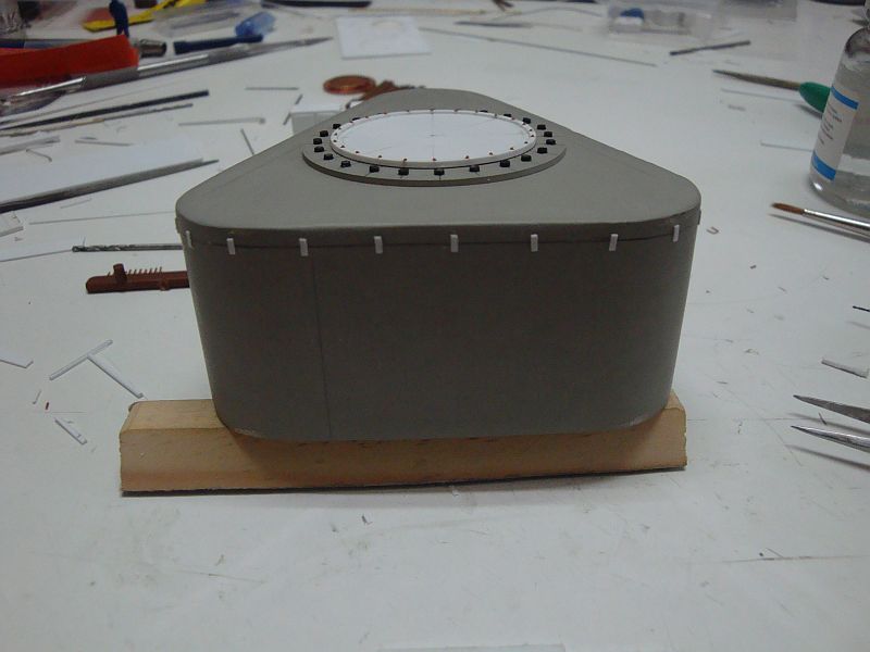
Hello all, Break time, so more pictures to post. Here goes. The rear panel wall in upright position. fitting in the reinforcing T-beams. Fitting in the second skin, to provide an installation flange for the window panes (clear plastic). The front skins are in place. The finished product. Plotting the window frames. cutting out. Separating the frames. A frame awaiting finishing. A finished frame. The nine frames required for the bridge. The bolt heads as supplied by Tichy Train Group. A close up of the bolt heads. The first frame. The nine frames ready for putting in place. An internal view of the bridge, displaying the window frames. The equipment in place. A figure sited adjacent to the equipment panel. Shall be posting more pictures next Wednesday, as tomorrow is holiday.

-
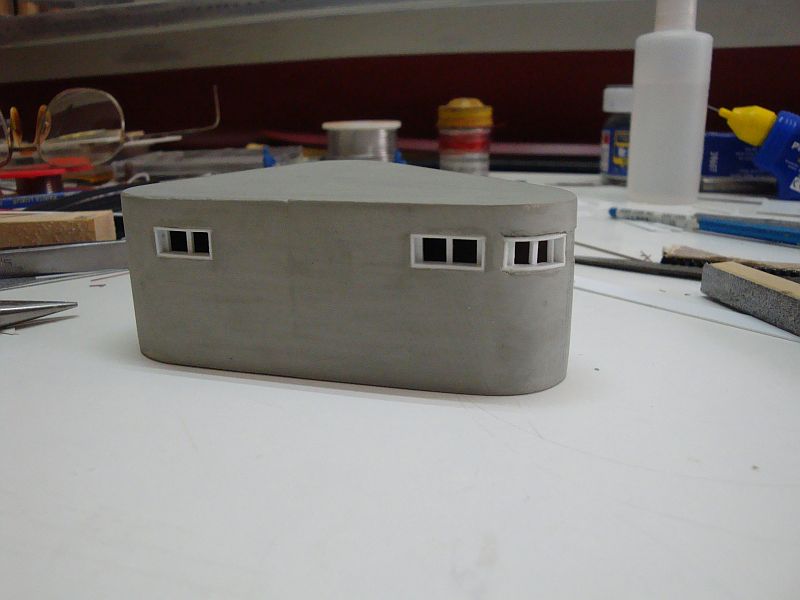
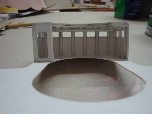
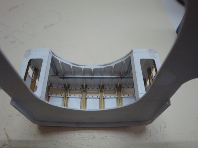
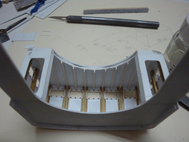
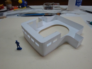
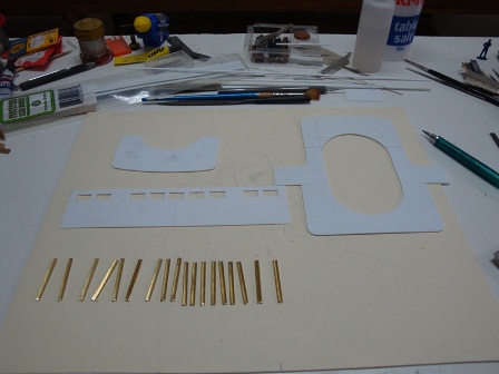
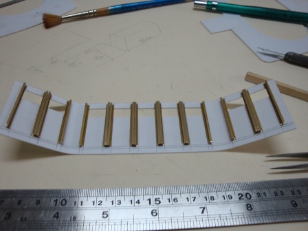
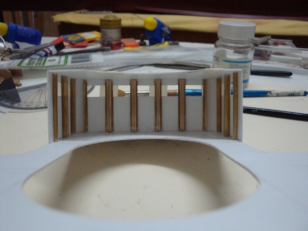
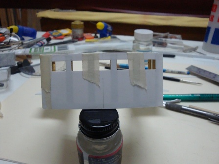
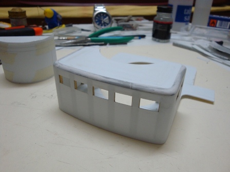
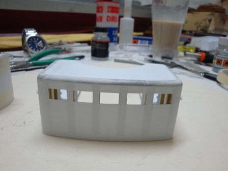
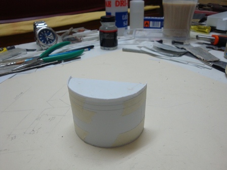
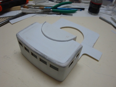
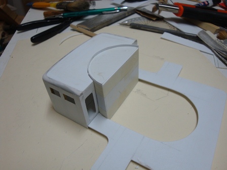
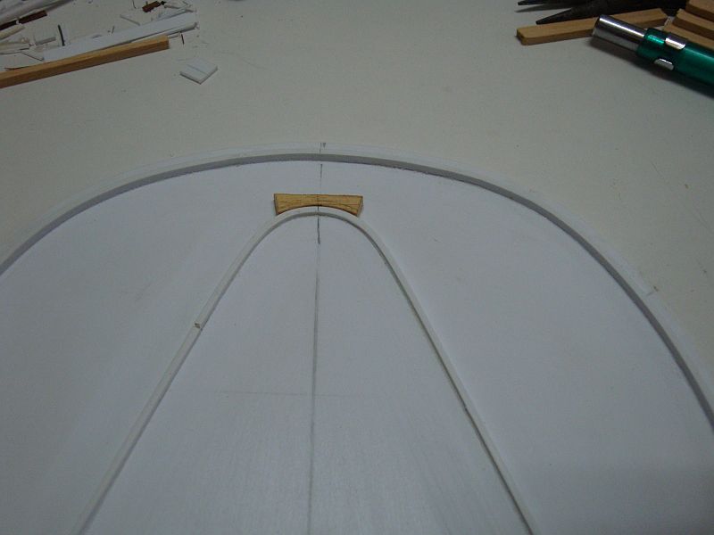
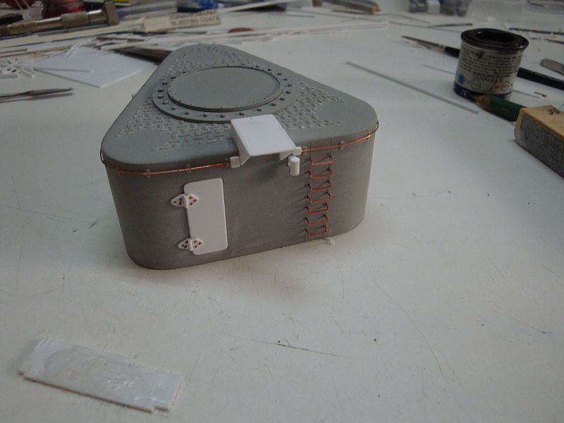
Good morning all, Today, I am posting the pictures related with the construction of the admiral's bridge, or the wheel house as some people may call it. Here goes, The first attempt. Wasn't so happy - so I decided to scrap it. A fresh start - the main pieces required for the build. The brass stiffeners in place. A rear view of the bridge, displaying the inside. A front view. The rear panel walls fitted in. Creating the circular edged roofing. A view from the front. The rear panel wall, fitted on a circular jig to permit detailing and finishing. Checking for correct fitting. A view from the rear. The start of detailing - the mounting rack for the electrical and communications equipment, together with the side doors; allowing entrance to the armoured tower. Shall be posting more pictures during break.
-
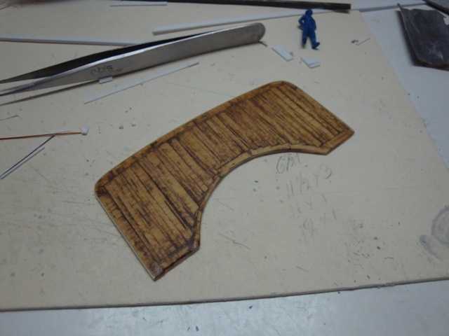
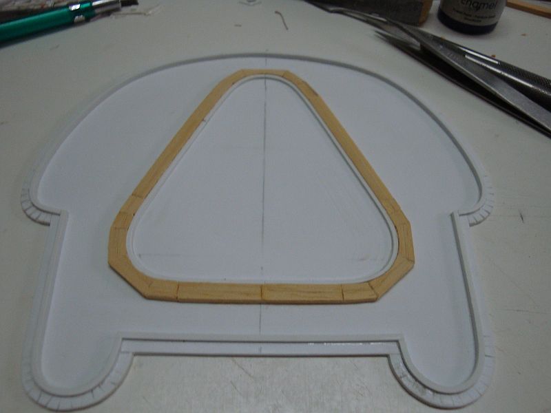
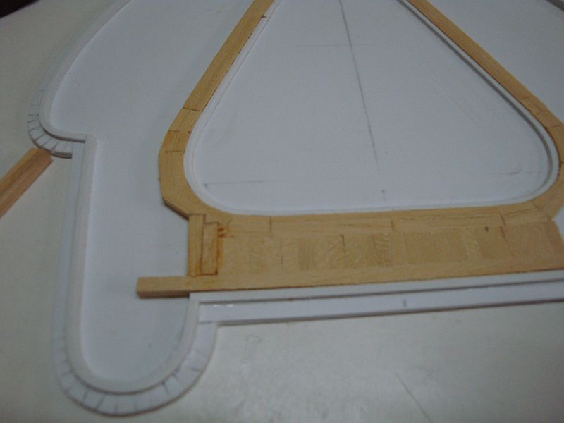
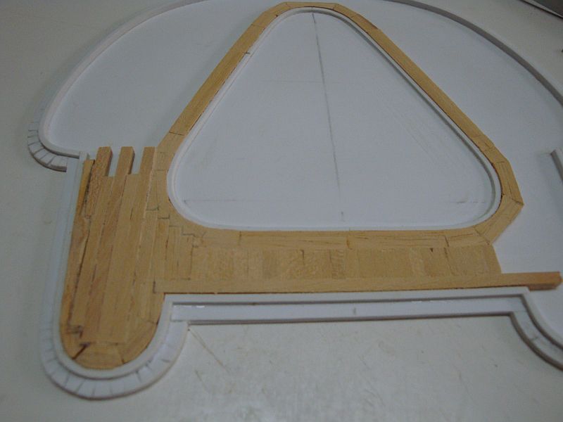
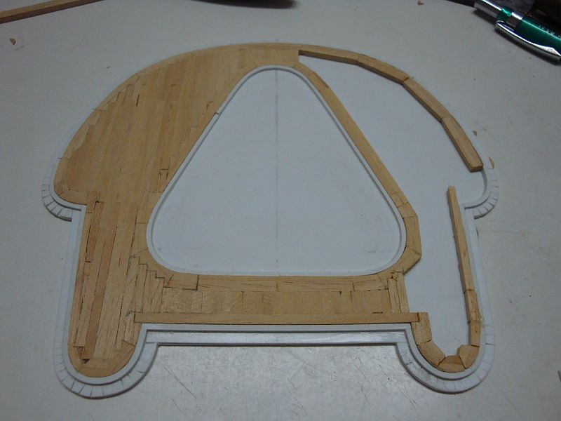
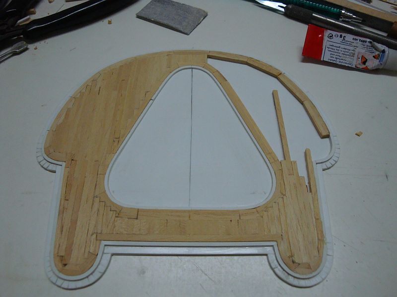
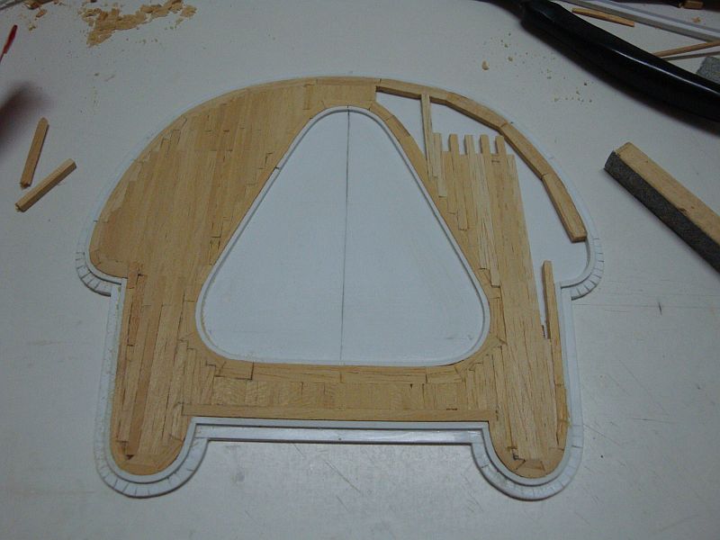
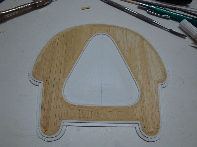
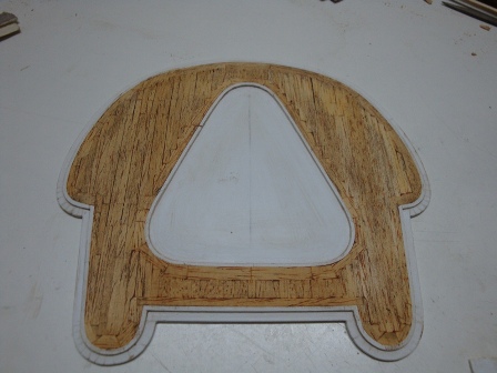
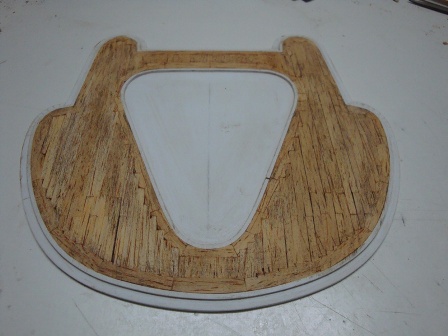
Good morning all, Today I am posting the construction pictures related to the construction of the tower observation platform balcony. Here goes. The first piece of planking. The inner ring. Starting off with the rear planking. Moving towards the left hand side. The left hand side is well under way. Half of the planking is ready. Starting off with the right side. Nearly there. The first step is ready. The planking is weathered. A view from the front. A view from the side. Shall post more pictures in due course.


-
Good morning all, Hello Popeye, Sjors and Joe, Thanks for looking and for you constant encouragement and support. Today, I shall be posting the last pictures related with the construction of the main range finder/radar station. Here goes. Shall post more pics tomorrow.
-
Hello Popeye, I missed out some posts. Brilliant work mate, the paint job is a wonder and really enlighted the hull. Looking forward to see more updates.
-
Good morning Alex, That's some fine planking you have there. The overlapping is just wonderful and exact. Looking forward to see more of this.
-
Hello Sarah, Thanks for looking in and for the kind words.
-
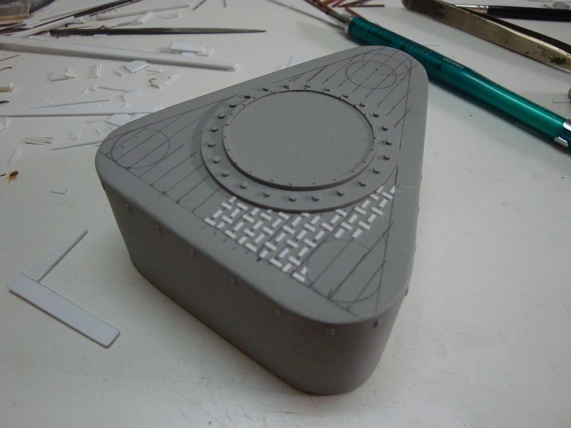
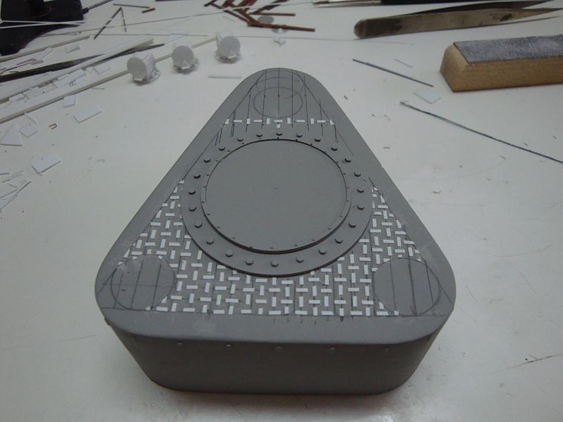
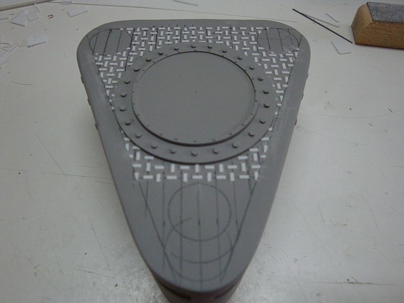
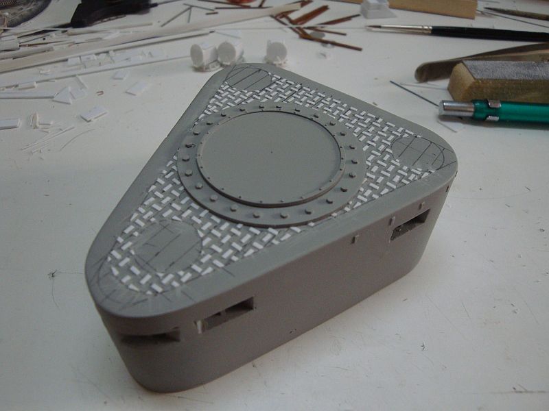
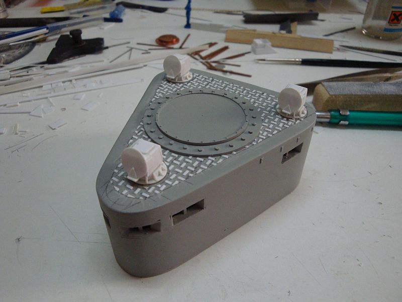
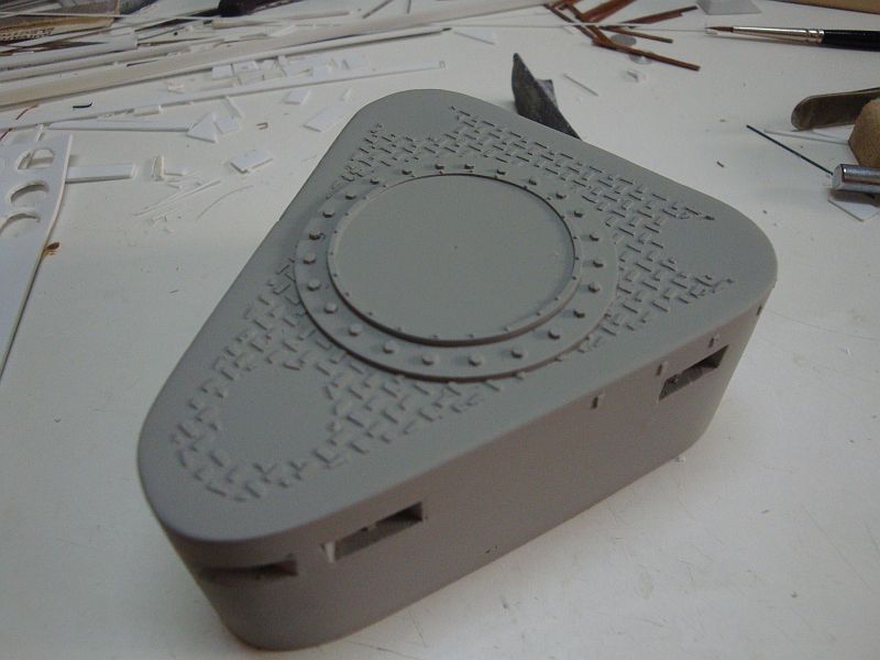
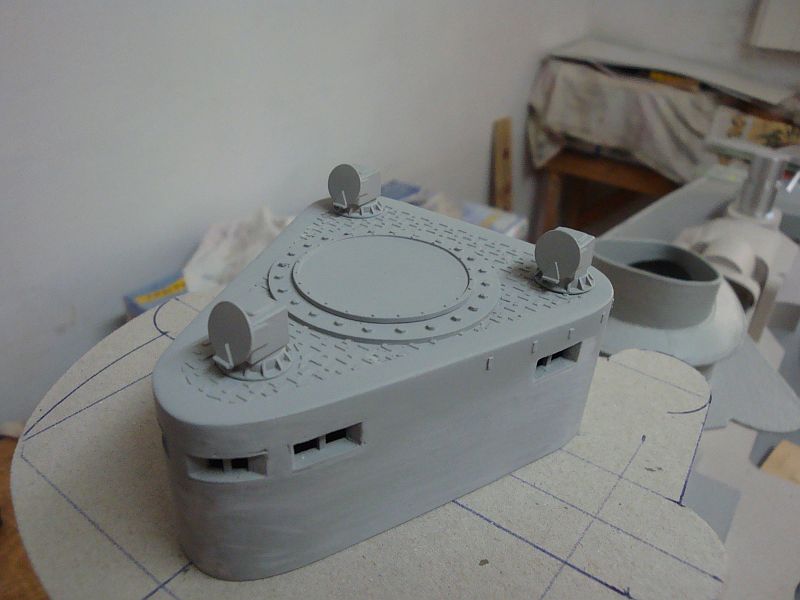
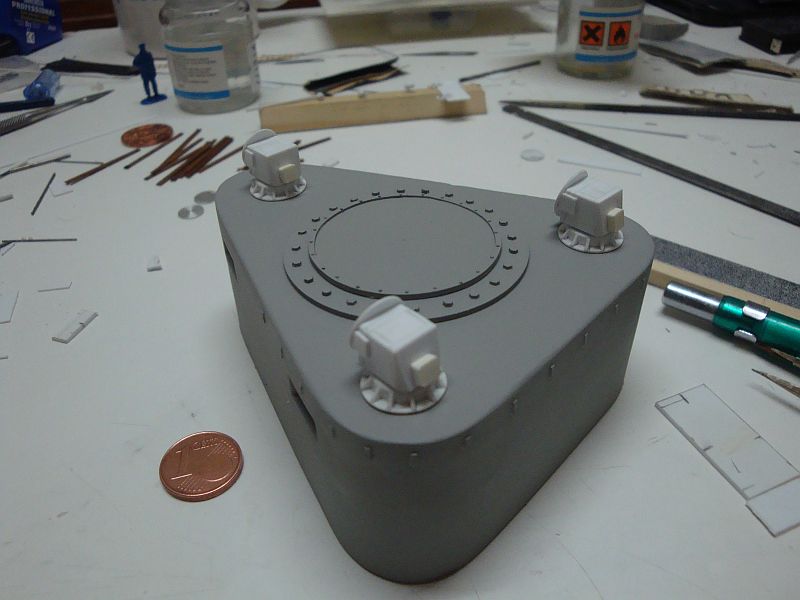
Hello all, Have some more time, so here goes. Starting off with the non-slip flooring. The first bit ready. More than half of the hard work is over. Closing in. Finally the non-slip flooring is ready. A view of the top with the armoured periscopes in place. The final appearance. The armoured periscopes, with their first coat of primer. An overall view of the radar assembly. A rear view. Shall try to post more.
-
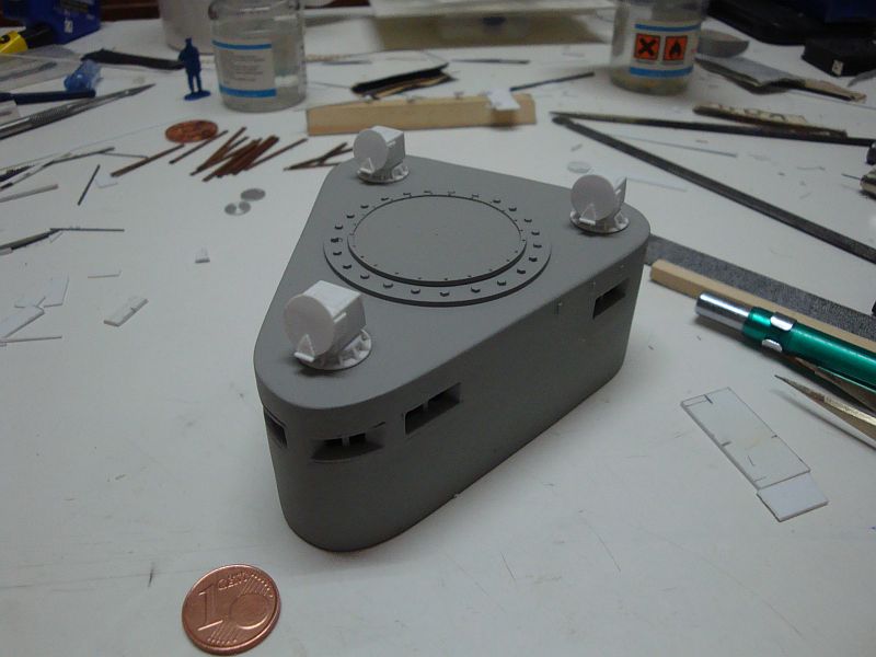
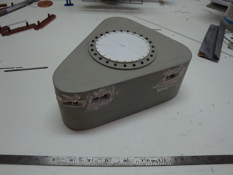
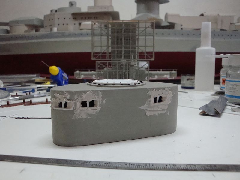
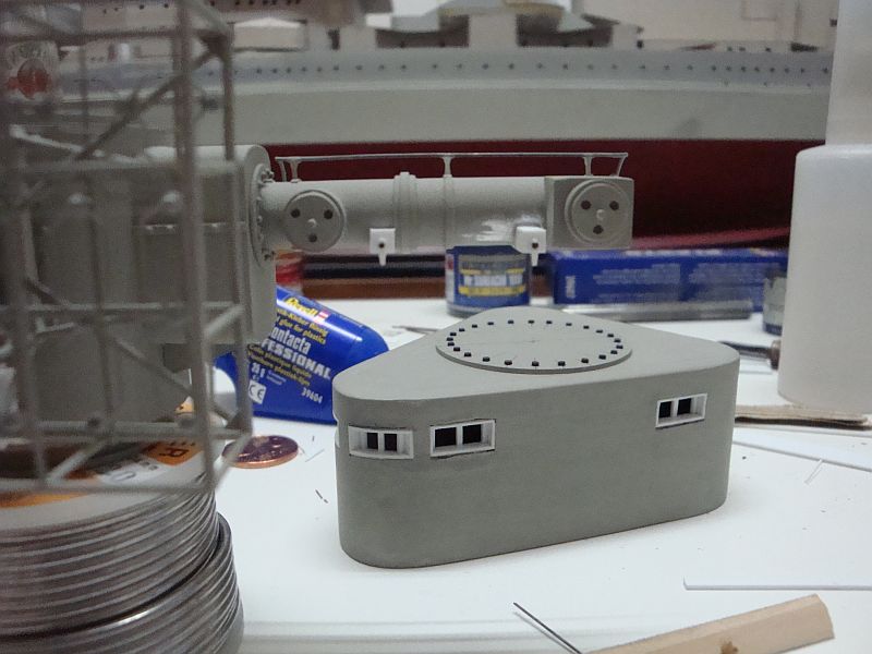
Good morning all, First of all I would like to thank you fine fellows ( Alex, Ben, Popeye, Pat, Augie, and all the others) for your kind and warm words. As promised, I am posting more pictures, related to the construction of the main range finder/radar installation. Here goes, The inside view of the access hatch. The radar assembly temporarily placed on what is to be the final resting place. A view from the front, showing the difference between the two range finders. The access for for the armoured observation post. The mounting brackets feet for the electrical conduit. The first base required for the armoured periscope housing. Three are required for this assembly. The second base under construction. The first armoured periscope housing ready for the next step. The three armpoured periscopes, are ready for the final detailing and finish. A view from the rear. A side elevational view. The radar assembly. Another view. Starting off with the lining for the non slip flooring. Will post more in due course.
-
Hello Amfibius, Thanks for looking in and for the kind comment.
-
Hello Daniel, Thanks for visiting. As regards to your question, I prefer not to use photoetched parts when possible, as this must remain a scratch built project. Of course, some parts have to be purchased - but I shall keep that to a minimum.
-
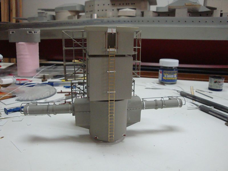
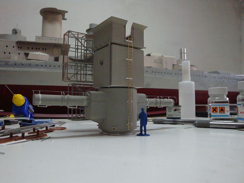
Hello all, Hi Popeye, Thanks mate; it's always a pleasure hearing from you. Found some free time so I am posting more pictures. Here goes. A side elevational view. Oops - this one must have skipped away. An internal view of the open observation post. The lock flange assembly. The lock flange in place. Filling off the gaps. Putting the brass access ladder in place. A rear view of the assembly with a 1:72nd figure, for comparison of size. The four locker cabinets required for the open observation post under way. The four cabinets, displaying the doors and hinges. The four cabinets ready for finishing. The communications set module for the open observation post. The exhaust air ventilation cowling, equipped with a fire damper. The cover hatch. The access hatch, allowing passage from the open observation post to the closed observation post, located beneath, together with the access cover hatch. Shall be posting more pictures tomorrow.
-
Hello Daniel, I record having seen this before, but viewed it in detail. That's a very nice story, and proves that tradition and history prevail over all. The model is a wonder, especially when back with it's rich history. Well Done Daniel.
- 33 replies
-
- 2
-

-
- trinkstein
- frigate
- (and 2 more)
-
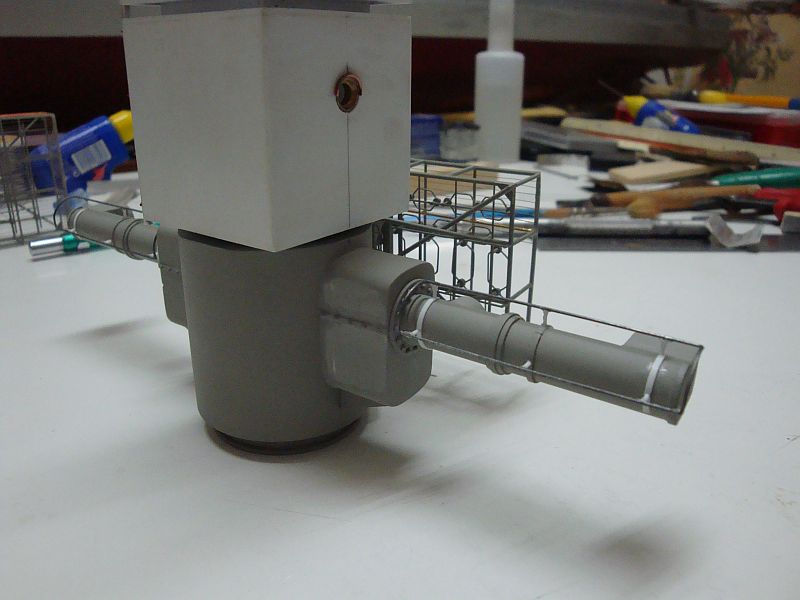
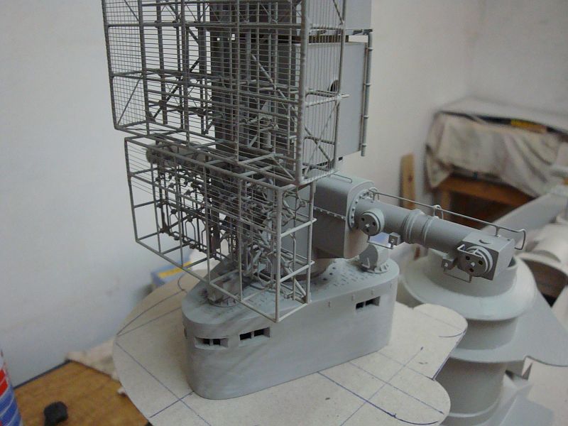
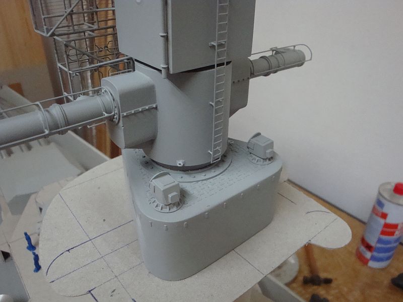
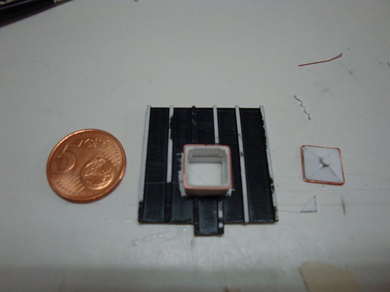
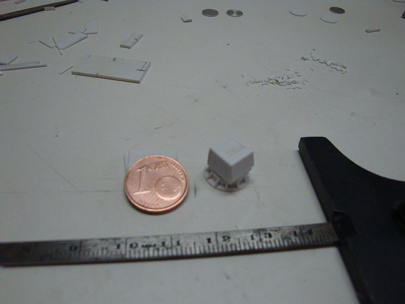
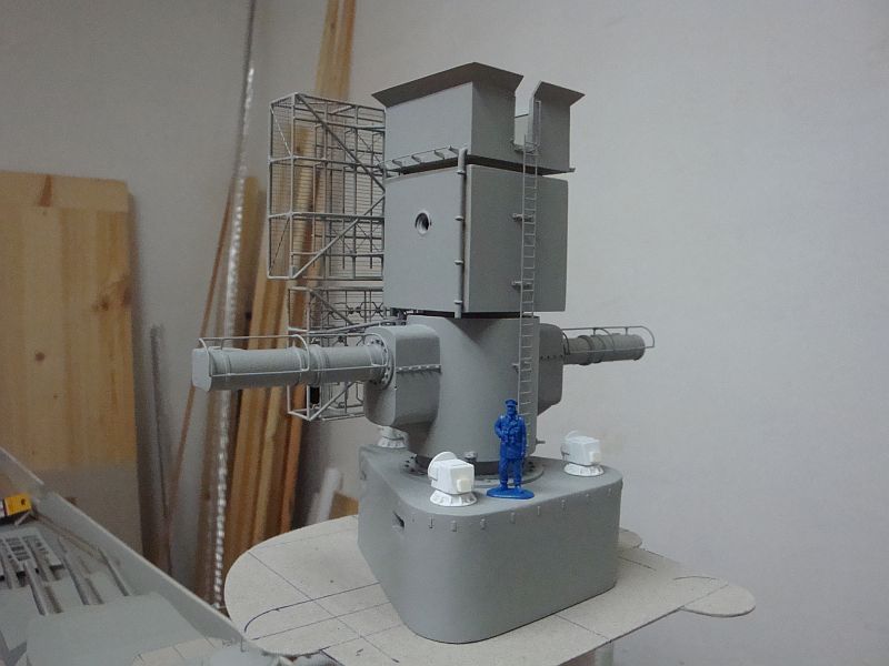
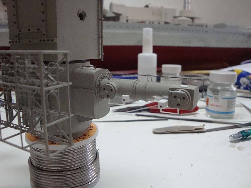
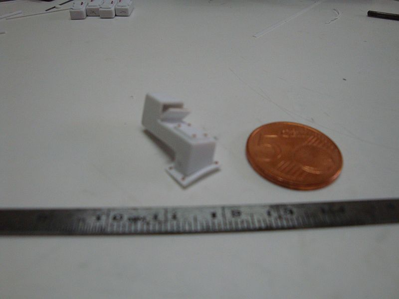
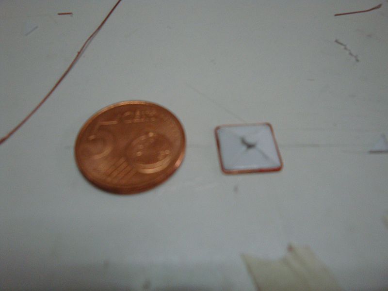
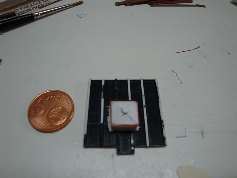
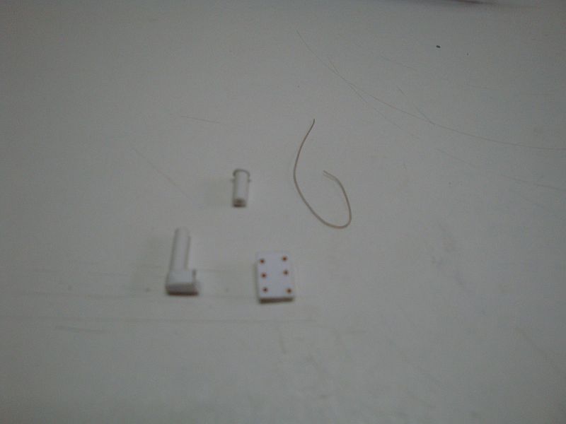
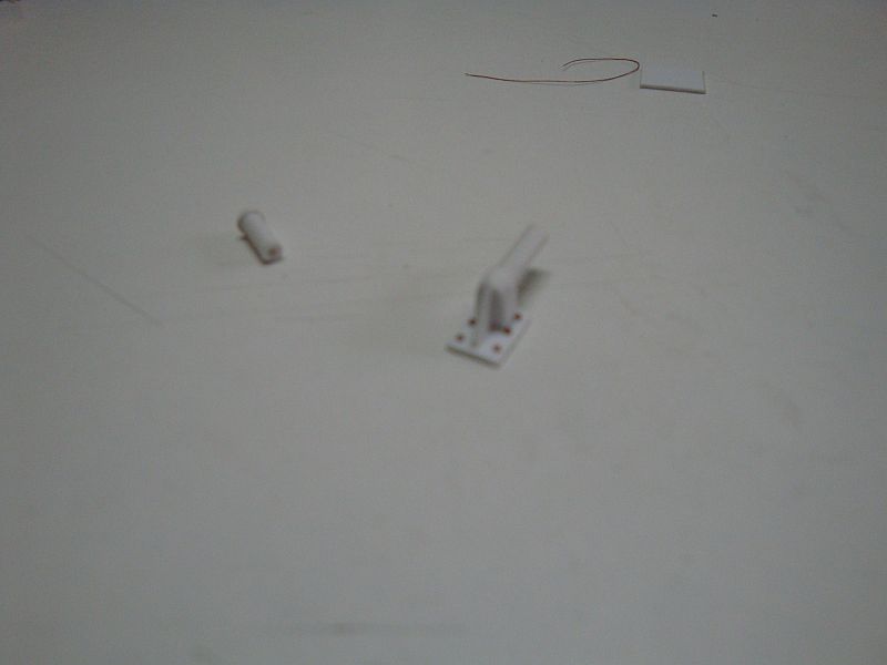
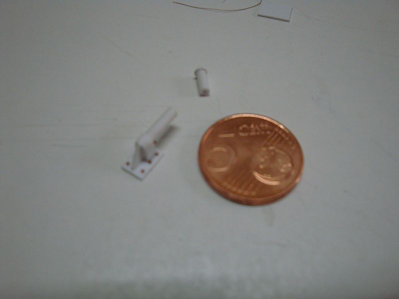
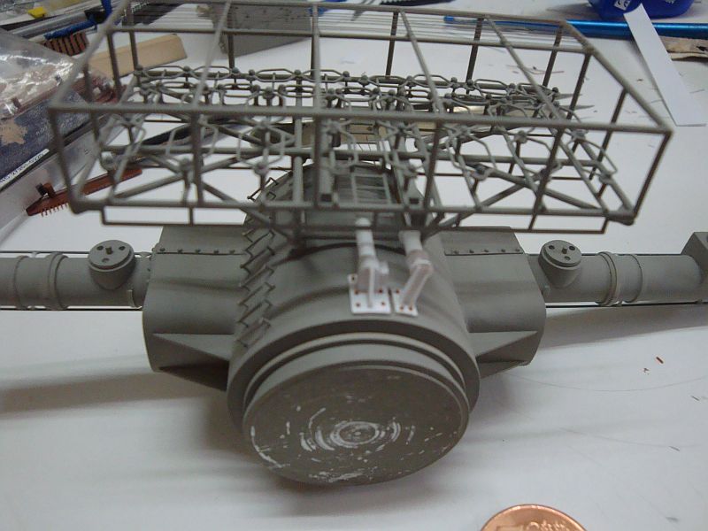
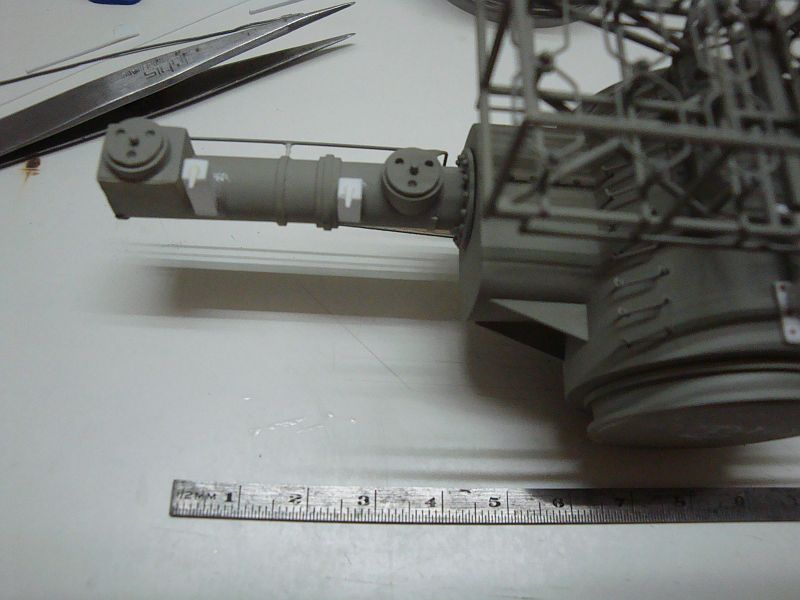
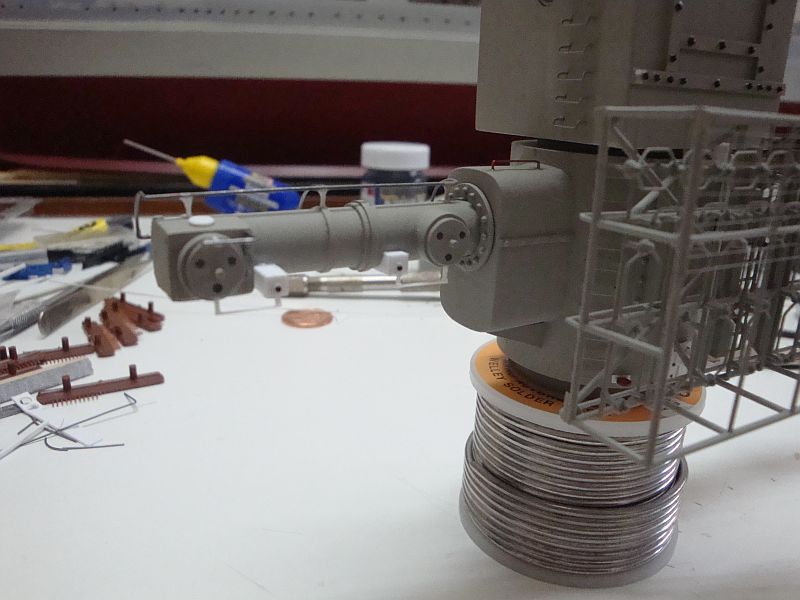
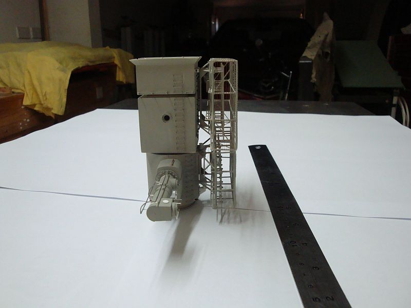
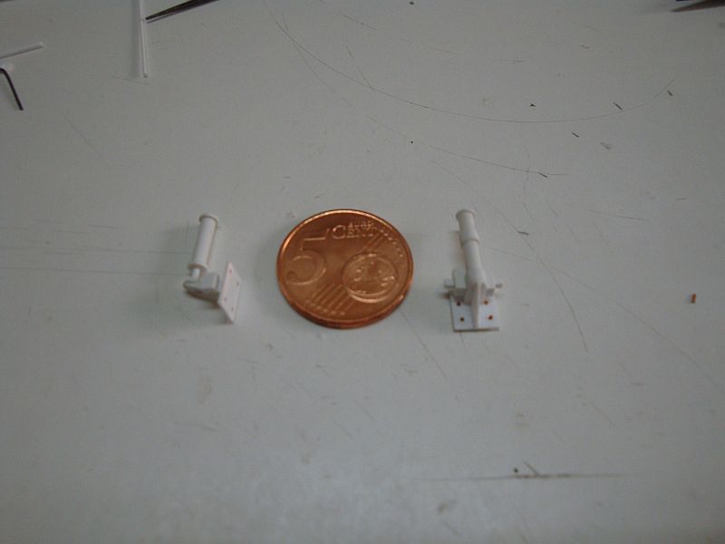
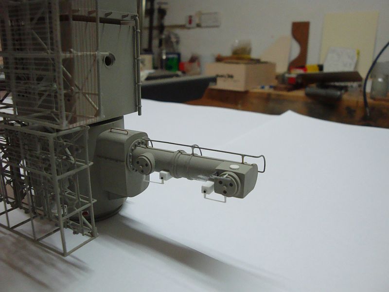
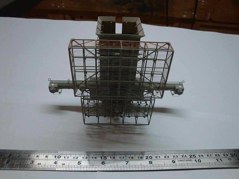
Good morning all, Hello Joe, Thanks for looking in. Some more pictures related to the construction of the main rangefinder/radar station. Here goes, A side elevation of the station. The main components of the radar stabilizer system. The radar stabilizer under assembly. The radar stabilizer placed adjacent to a 5 Euro cent coin for comparison of size. A close up shot, showing the stabilizer and the earthing system in place. The housing with the swing arms - these arms were driven by electric motors, and used to turn the armoured shutters of the lens housings. A view of the other side, including the ;locking bolt on the swing arms. The arms and the linkages are now in place. The moment of truth - the radars in place. A side view. The stabilizer and the earthing device for the FuMO 27 radar. A close up view of the arm housing displaying the details involved. A close up view, showing the pneumatic piston on the stabilizer. The rear side of the range finder housing, showing the lift up cowlings. A main shot of the assembly. Shall be posting more pictures tomorrow.
-
Thanks Pat, always a pleasure.
-
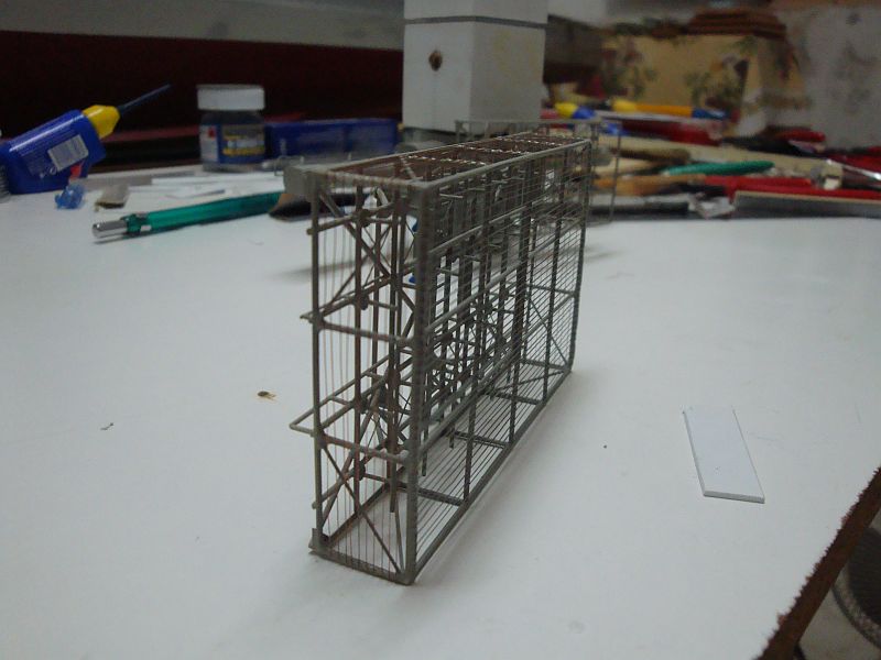
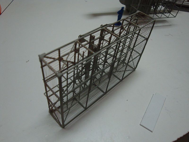
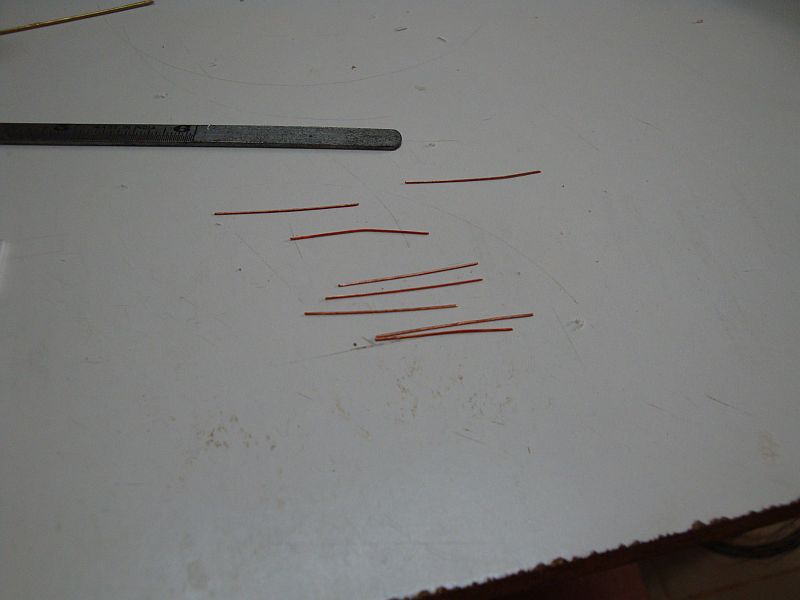
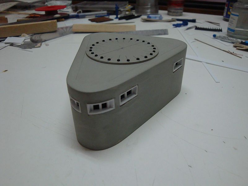
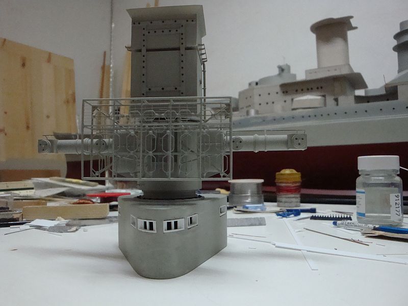
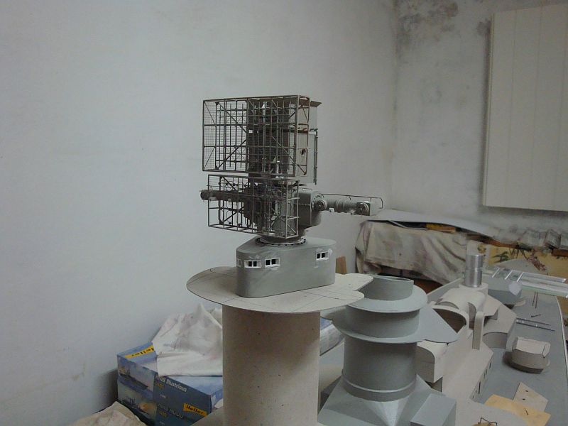
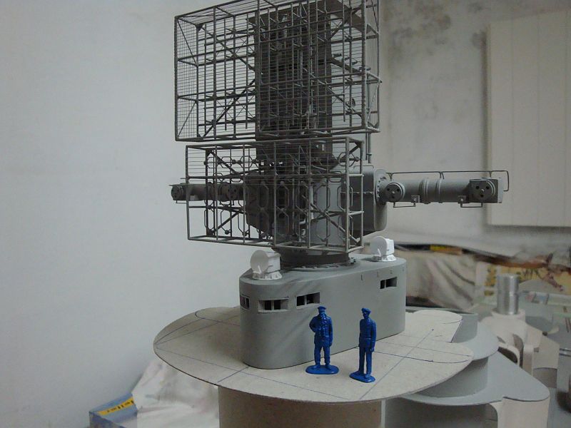
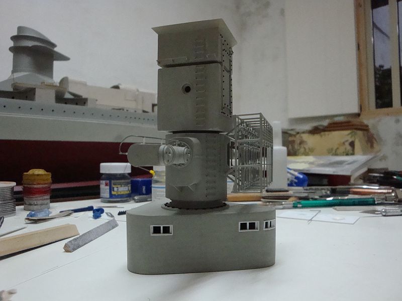
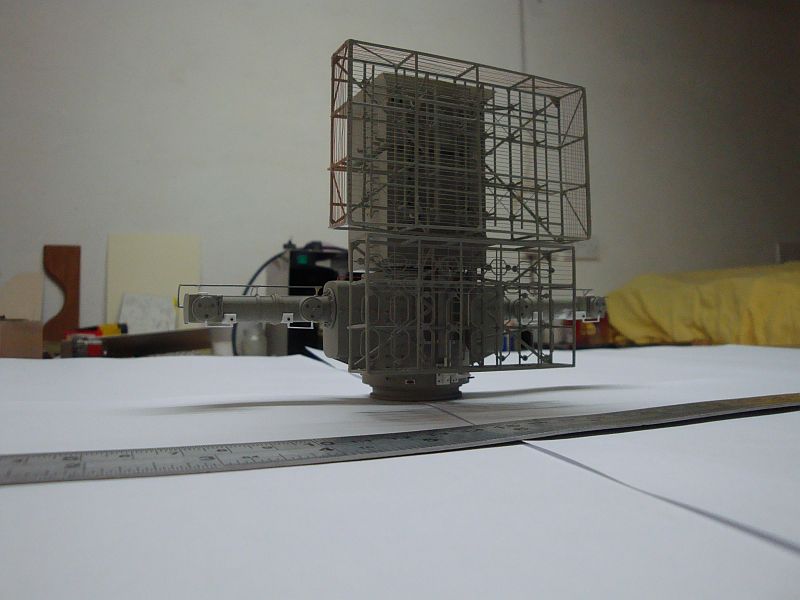
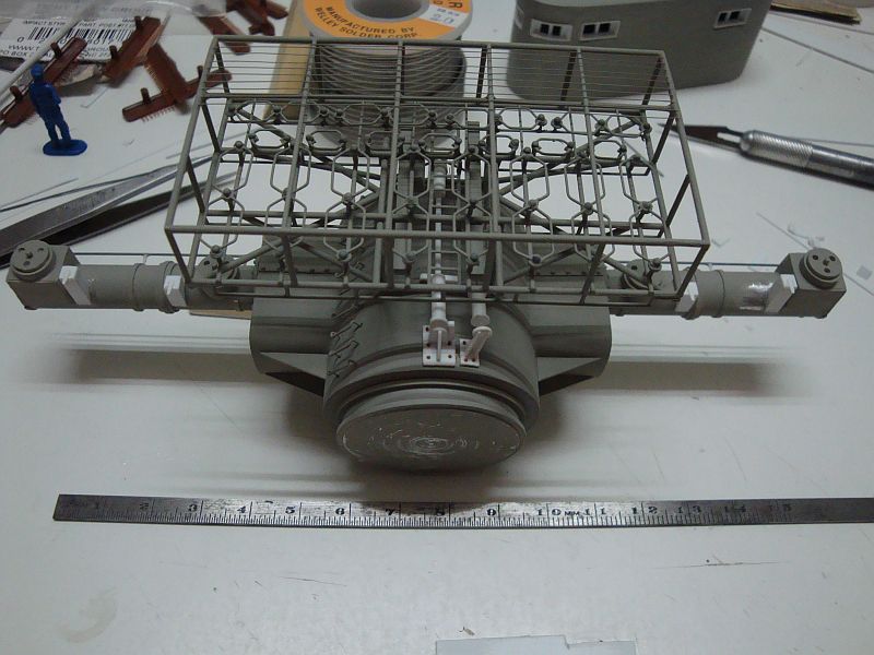
Good morning all, Hello, Cherry, Popeye, Ben, Larry and Greg, thanks for looking in and for the kind comments. Today, I am posting more progress pictures related to the construction of the main rangefinder/radar installation. Hers goes. A view from the rear, displaying the stand on rails. The FuMO 27 radar with it's side protection mesh. Another view. Preparing the copper wire strips for the next step ladder. Forming the steps. The foot steps ready for fitting in place. The footsteps in place. The mounting bracket structure for the FuMO 27 radar. Another view. A view of the installation mounted on the armoured observation post. Note the cut out of the observation windows. The window frames required for the armoured observation post. The window frames in place. The mounting crown with it's locking bolts. A view of the whole assembly, lacking the FuMO 17 radar. Shall be posting more pics tomorrow. Thanks guys for your support.