g8rfan
-
Posts
178 -
Joined
-
Last visited
Recent Profile Visitors
1,342 profile views


-
 mtbediz reacted to a post in a topic:
USS Constitution by g8rfan99 - BlueJacket Shipcrafters - 1/98
mtbediz reacted to a post in a topic:
USS Constitution by g8rfan99 - BlueJacket Shipcrafters - 1/98
-
Coyote_6 reacted to a post in a topic:
USS Constitution by g8rfan99 - BlueJacket Shipcrafters - 1/98
-
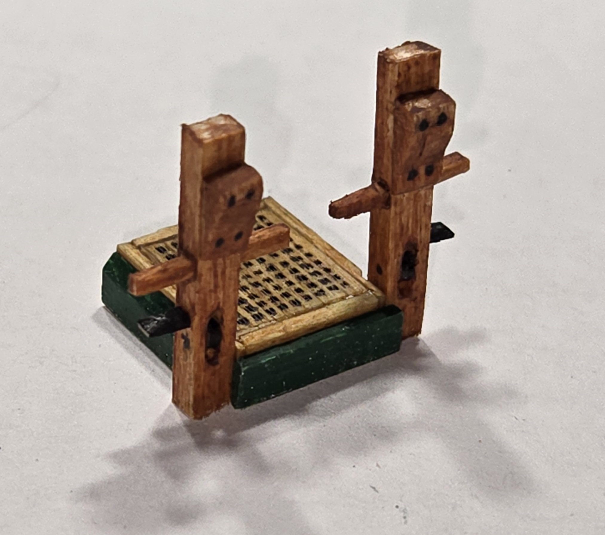
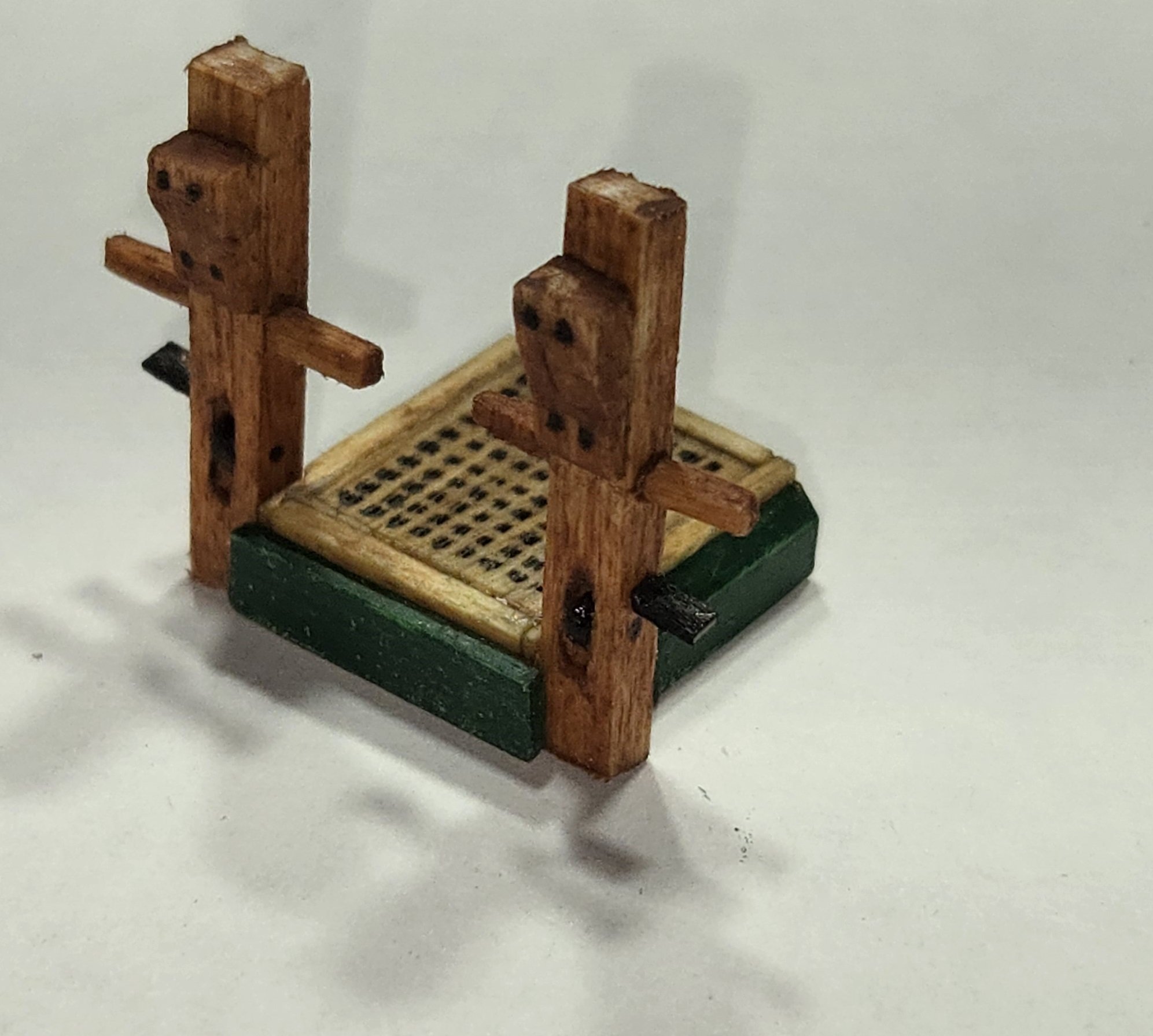
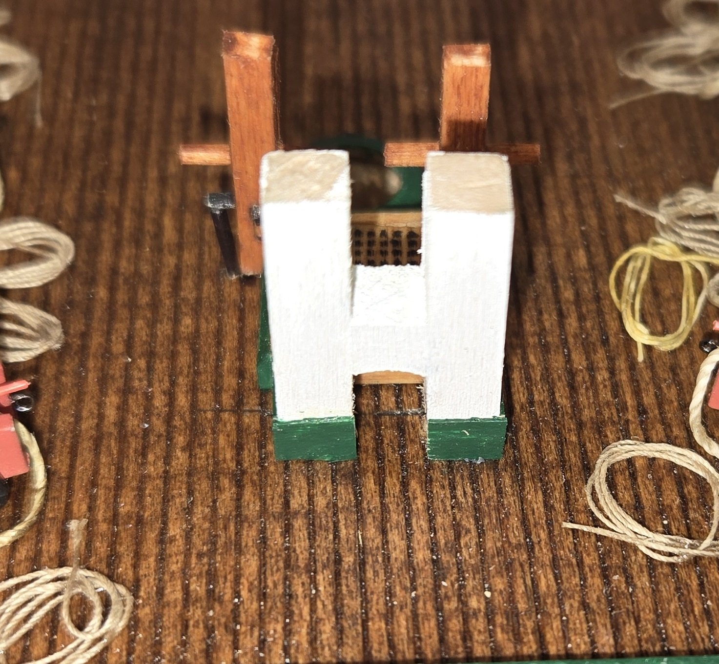
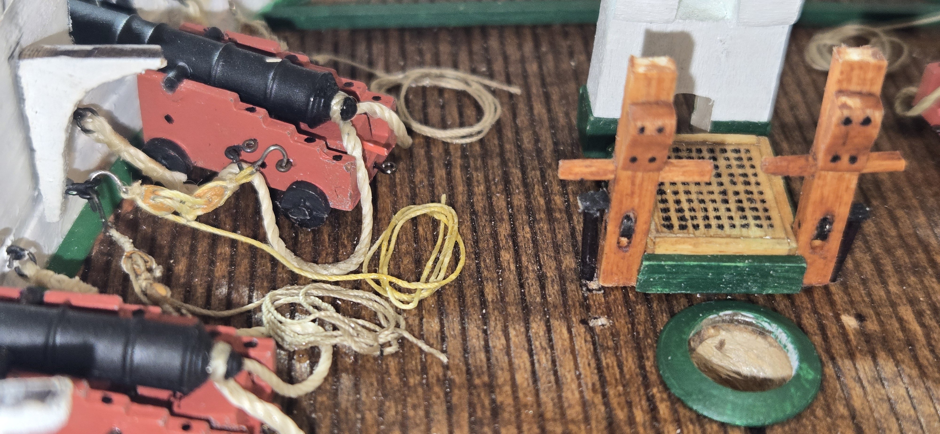
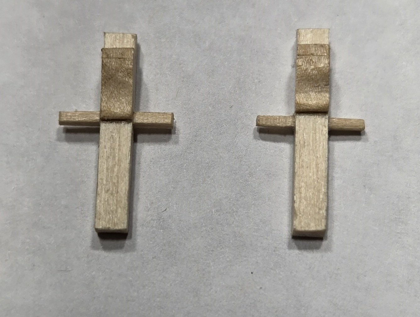
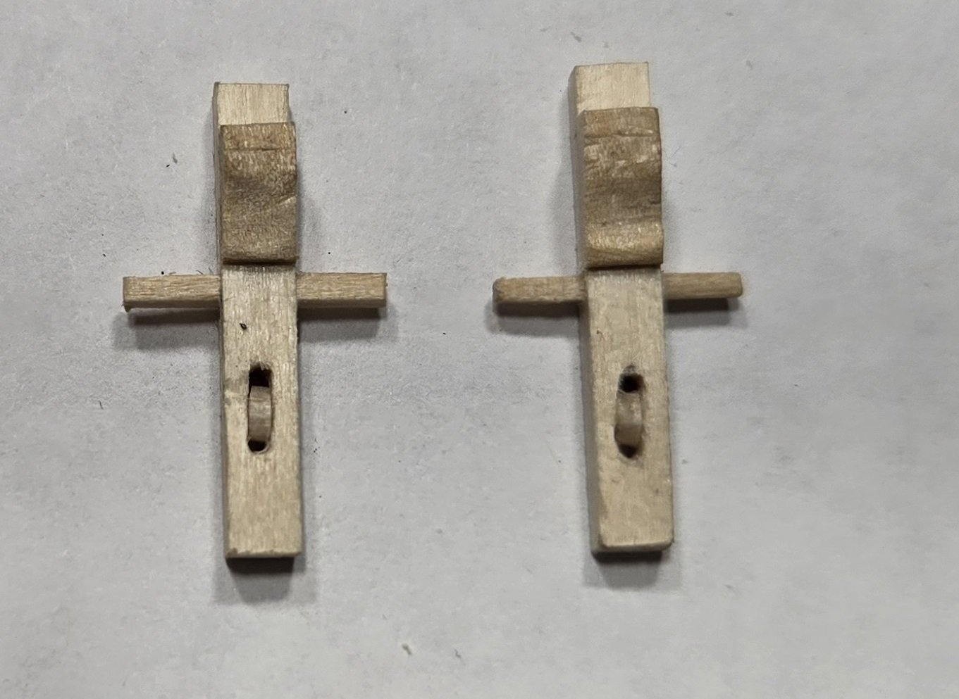
After failing to find any additional info one rider bitts, I decided to go with the wooden cross style bitts I mentioned above. In trying to establish exactly where the riders would be positioned on the deck, I first was looking at Lord's deck plans from 1927. I have this printed and hanging on the wall, covering the gun deck plan provided by BJ. I had gotten out of the habit of looking at the BJ plans, mostly relying on Lord's, but for what ever reason, I took a look at the BJ plan and wouldn't you know it, they show the wooden cross style bitts. I guess I should pay more attention to the plans supplied in the kit. I will say, it would be nice if the instructions didn't just say "the anchor chain cables and large iron bitts currently on the Constitution date from a later period", but would go on to say that these bitts were constructed of wood "as shown on the gundeck plan". Better yet, have an actual illustration of what they looked like and perhaps some dimensions. In any event, it confirmed that this is what should be in place. As I made my measurements to see where these would be placed on the deck, I quickly realized that the "pan" for the camboose was too wide. The aft riders are right next to the camboose, and with it as wide as it was, the riders would also be too far outward. Fortunately, I had not yet glued this assembly down on the deck. The camboose was easily separated from the pan, which I then modified to fit the camboose tightly instead of having a gap on either side. The riders were made from 1/8x1/4 stock. The plans indicate that the forward rider extended the length of the scuttle, but on the current ship, it stops just in front of the scuttle. I chose to make mine so it stopped in front. The aft riders are just slightly longer than the pan for the camboose. On the plans, both of these bitts show the cross piece extending from one post to the other. Hoever, if I did this on the aft rider bitts it would be right in front of the camboose "oven" area and I didn't think that would be very practial. So the aft bitts I made as crosses and the forward bitts are all the way across. here they are with stain and ring bolts in place


-
Coyote_6 reacted to a post in a topic:
USS Constitution by g8rfan99 - BlueJacket Shipcrafters - 1/98
-
ccoyle reacted to a post in a topic:
USS Constitution by g8rfan99 - BlueJacket Shipcrafters - 1/98
-
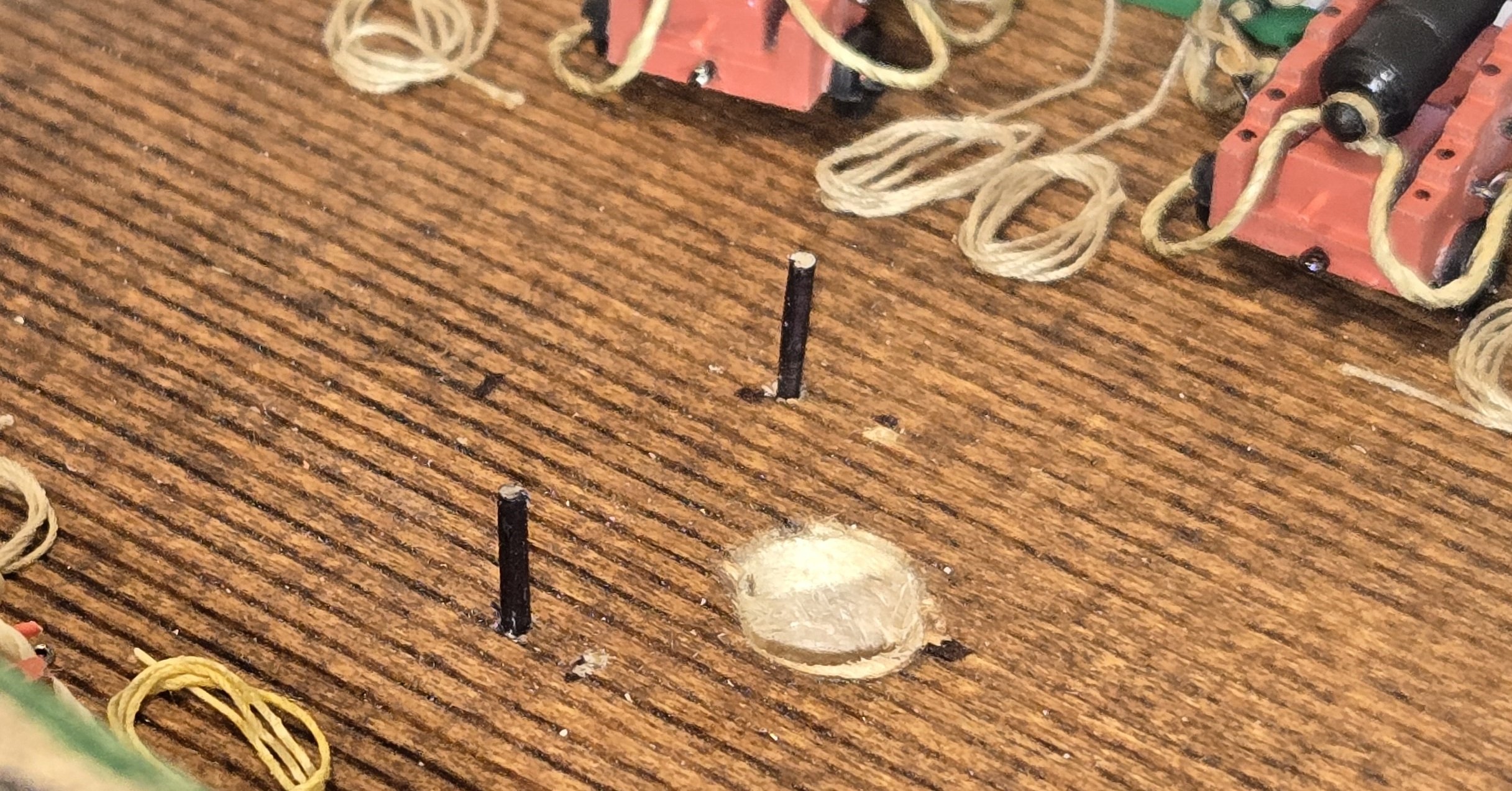
Moving right along, I decided that even though the ship did not use chains at this time, there must have been some sort of cable stop in the manger. I could not find anything to support that, but it seemed logical and it's a nice feature. I modeled the stopper after the one currently on the ship and again used known dimensions of surrounding items to determine the dimensions of the stopper. It was actually a complex little assembly. Everything was made from wood except the crossbar, which is 24 ga wire. The little balls on the end of the crossbar were made from epoxy putty The stoppers on the ship currently do not have anything on the outsides, however, the messenger cable has to run around these and so there must have been something there for the cable to ride along. I decided to put rollers similar to those on the side of the anchor bitts. These were made from styrene. The notch in the front of the base is there to fit over the top of the manger rail. In addition to these, there is also the stopper bill pulley for the messenger cable. The timbers this pulley rests on were of course wod. The pulley and the bracket to hold it were cut from flat stock styrene. Sorry for the dark photo. That was about it for the manger area


-
 Der Alte Rentner reacted to a post in a topic:
USS Constitution by Der Alte Rentner - Model Shipways - 1/76
Der Alte Rentner reacted to a post in a topic:
USS Constitution by Der Alte Rentner - Model Shipways - 1/76
-
Russ2025 reacted to a post in a topic:
USS Constitution by Der Alte Rentner - Model Shipways - 1/76
-
Hey Peter I have been quietly following along with your build, but after reading the comment by Bitter end, I just had to reiterate. It truly is amazing what you have done with bare wood. Your precision and craftsmanship are superb. Fine job!
-
g8rfan reacted to a post in a topic:
USS Constitution by Der Alte Rentner - Model Shipways - 1/76
-
KurtH reacted to a post in a topic:
USS Constitution by g8rfan99 - BlueJacket Shipcrafters - 1/98
-
g8rfan reacted to a post in a topic:
USS Constitution by Unegawahya - Model Shipways - scale 1:76
-
usedtosail reacted to a post in a topic:
USS Constitution by g8rfan99 - BlueJacket Shipcrafters - 1/98
-
I forgot to mention the other text references provided by the Navy Historical Command. They were HMS Victory: Her Construction, Career and Restoration – Alan McGowan (Naval Institute Press, 1999) Seamanship in the Age of Sail – John Harland (Naval Institute Press She said the second one should be particularly useful and contained alot of illustrations. Unfortunately, neither of these is available online and the ones I have found for sale are a bit pricey. If anyone out there has this book I would be interested to hear what it has to say about the anchor bitts.
-
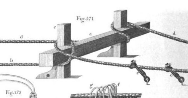
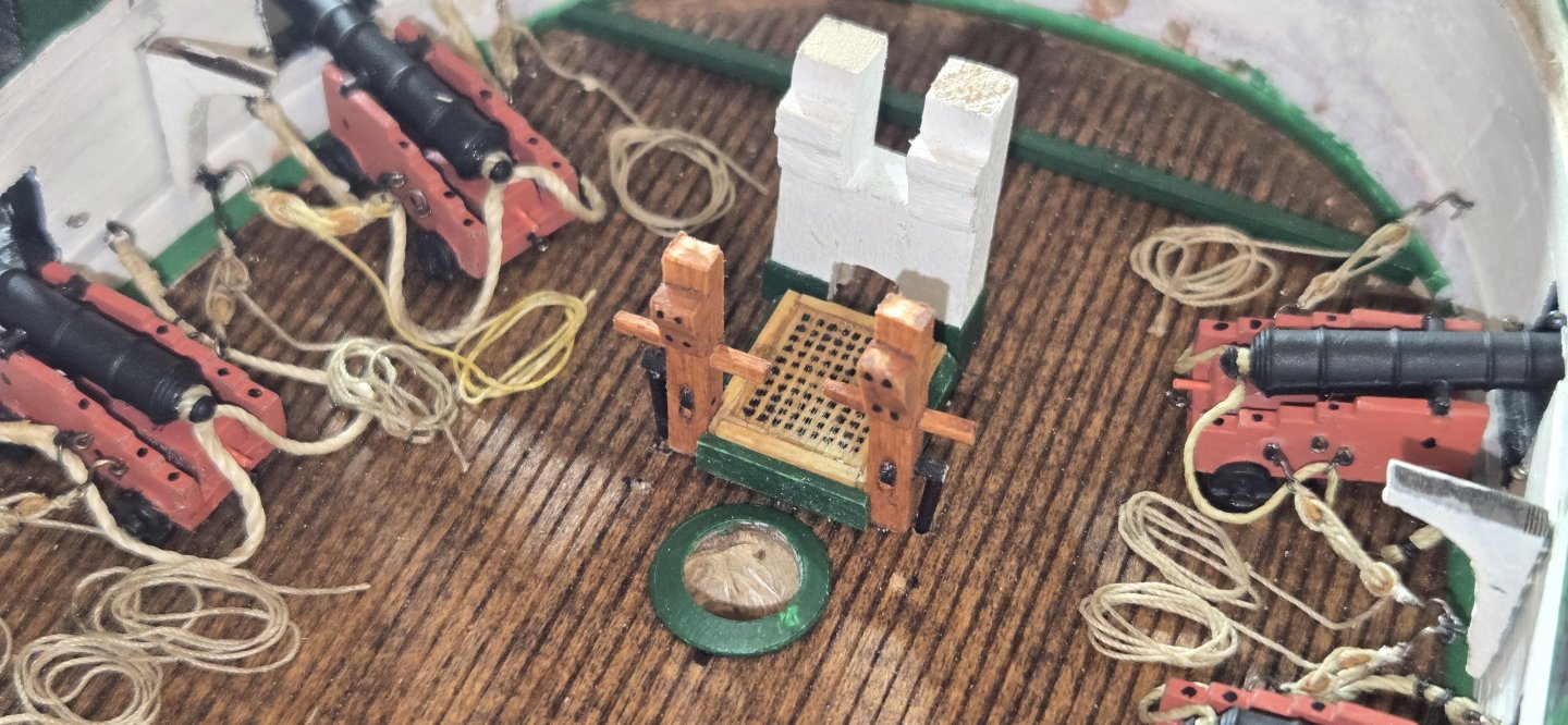
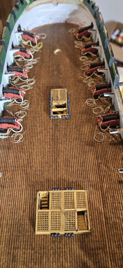
I've started working on the deck furniture. I still haven't had a lot of luck finding out what was in place of the large iron anchor bitts currently on the ship. I contacted the museum and they referred me to the Naval History and Heritage Command. They couldn't give me a definitive answer but provided several good references. The first was The Young Sea Officers Sheet Anchor (1819). It's a kind of text on seamanship and fortunately is available online. In it, they mention the securing of anchor cable to the anchor bitts and gave the following diagram This seems to be pretty standard for ships of the time. I presume in addition to the anchor bitts on the ship now, that a cross piece like this would also have been at the end of the cable riders. I'll probably go with something similar unless I hear something better from anyone out there. I go started with the anchor bitts just in front of the foremast. I used 1/8 squarestock to make these. As mentioned by Jon in his build, there are no dimensions to be found, so everything was pretty much eyeballed and based on comparison to some known dimensions of other items in photos. The height was easy enough since it is based on where the spardeck is to be. The little support knees were spaced to accommodate the height of the deck beams. The cross pieces are a single piece. To get these in place, I first drilled an appropriately sized holed and then squared that up using a square rat-tail file. Lastly the sheave was made from 3/32 dowel that I sliced a tiny piece off of. The hole was created by drilling three small hole and then carefully carving out the remaining wood and finally cleaning up the hole with a flat file Next came the grate for the scuttle that I apparently missed when constructing all the other grates on the deck. This was made similarly to the others using the persimmon wood I still had and the laser engraver. The coamings are slightly different than the other grates. Here's everything after staining and painting but before installation. Note the little tabs on the sides for the rollers that will be put in place once on the deck Next up was the bowsprit bitts. These are pretty stout timbers. Again, I couldn't find any actual dimensions, so I just guessed again comparing to everything around it. From what you can see on the virtual tour and looking at Lord's 1927 deckplan, the timbers are square, with space in between for the bowsprit notch being the same dimensions. So I just took the width of the scuttle and divided it by three. Lord's 1931 deck plan indicate this hatch was three feet wide, so 12 inch timbers (1/8"). The height again was simply based on fitting the spardeck and the support knees positioned to accept the height of the deck beams. The crosspiece in the middle makes a hole to receive the notch of the bowsprit. Instead of making this square, I used a 3/8 dremel sander to curve the bottom. That way, I only need to cut the sides of the bowsprit to make the notch. The coamings around the botttom were made from some hull planking I had left over that I thinned down a little bit, probably to about 1/64"". The wholle thing was secured to the deck using wooden dowels I made from thinned down toothpicks. I notched a 3/8" dowel to be used for the bowsprit so that it would fit the bitts and used that to make sure it was positioned perfectly to accept the bowsprit later and be straight. When installing the scuttle and anchor bitts, I first installed the side rollers. These were made from a 3/32" dowel that I thinned down further. Holes were drilled into the deck to accept the rollers and the bitts were placed on top. Everything was secured with 5 minute epoxy. Here's the final view looking forward


-
mtbediz reacted to a post in a topic:
USS Constitution by rvchima - Mamoli - 1:93
-
Hi Rod, Thanks for looking in on my build and I definitely appreciate the compliment. Wanting to put in alot of details, I'm sure I make it hard on myself, especially at our scale. If nothing else, it keeps me busy. Good luck with yours
-
Canute reacted to a post in a topic:
USS Constitution by rvchima - Mamoli - 1:93
-
g8rfan reacted to a post in a topic:
USS Constitution by mtbediz - 1:76
-
Welcome to the Connie group Rod. You are off to a great build. Look forward to following along. As slow as I am, I'm sure you will catch up to me soon and I'll have someone new to "steal" ideas from.
-
Thanks Gregg, appreciate the support and thanks to all the likes. Jon. I'll definitely give that a try.
-
Now that I have the forward guns in place, I'm planning to focus on the bitts and deck furniture for that portion of the ship. Originally, I didn't plan on putting much detail in the very forward part of the bow since it wasn't going to be very visible if at all, but I've decided to go ahead and put everything in place just because I will know it's there. Immediately, I had some questions. In the manger area, there are currently two chain stops, port and starboard I know in 1812, they did not have anchor chains, but instead, hemp cable. My question for all is would there still have been a similar stop for the cable? The second big question is the about the chain bitts. The instructions in the kit say "the large iron bitts" were not present in 1812. I assume these are what they are talking about: so the question is, what was there? Any help would be greatly appreciated


-
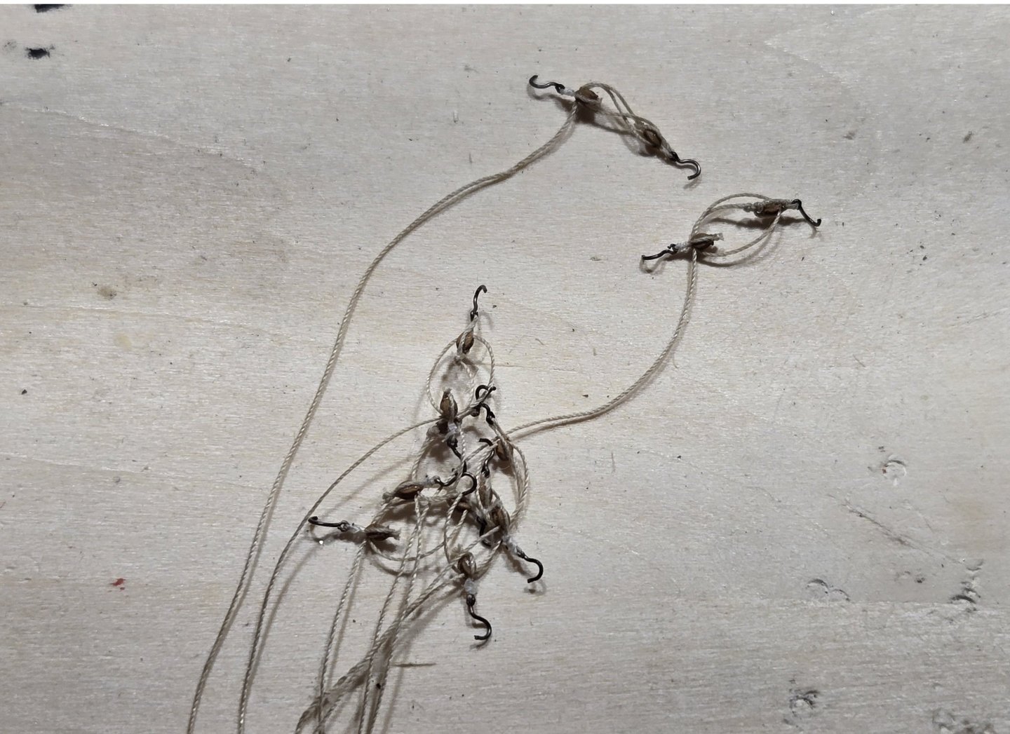
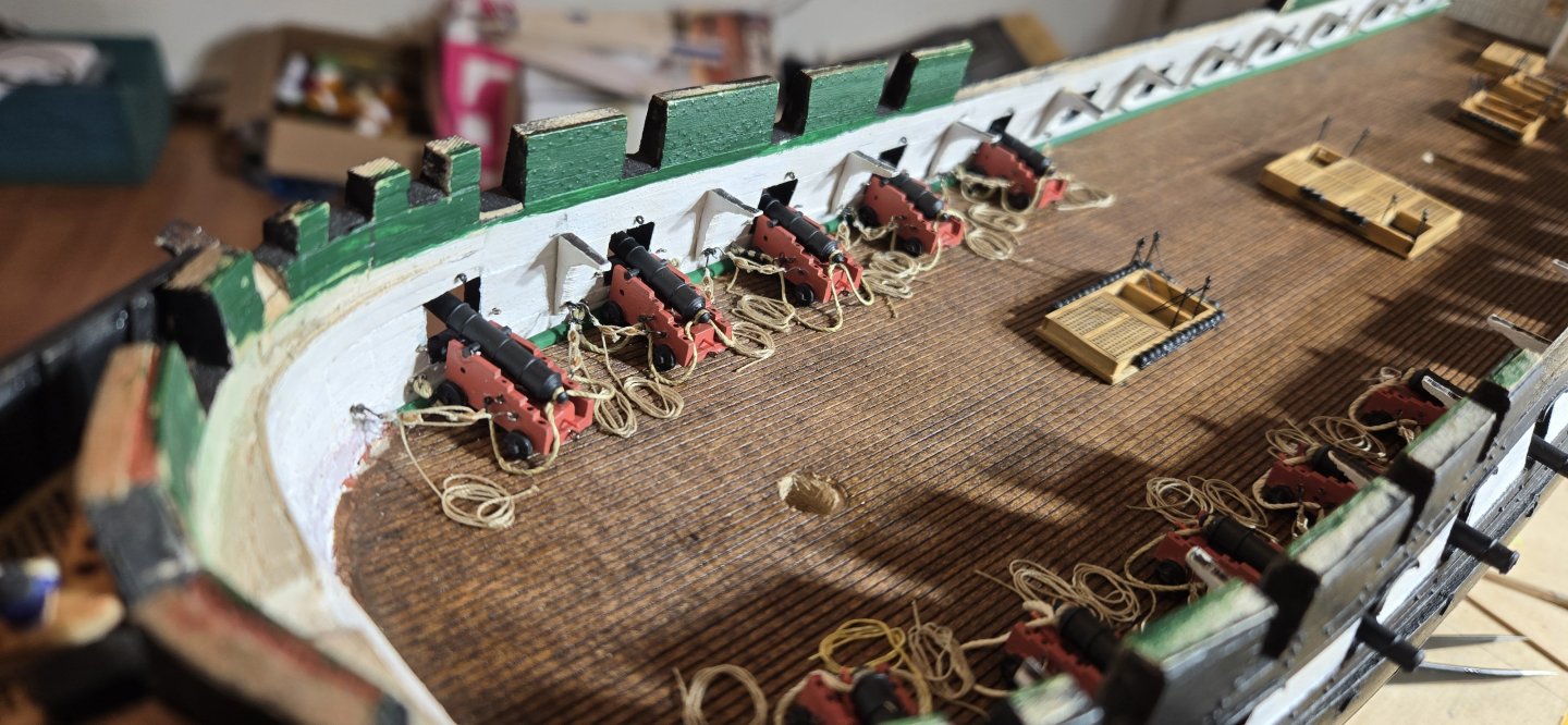
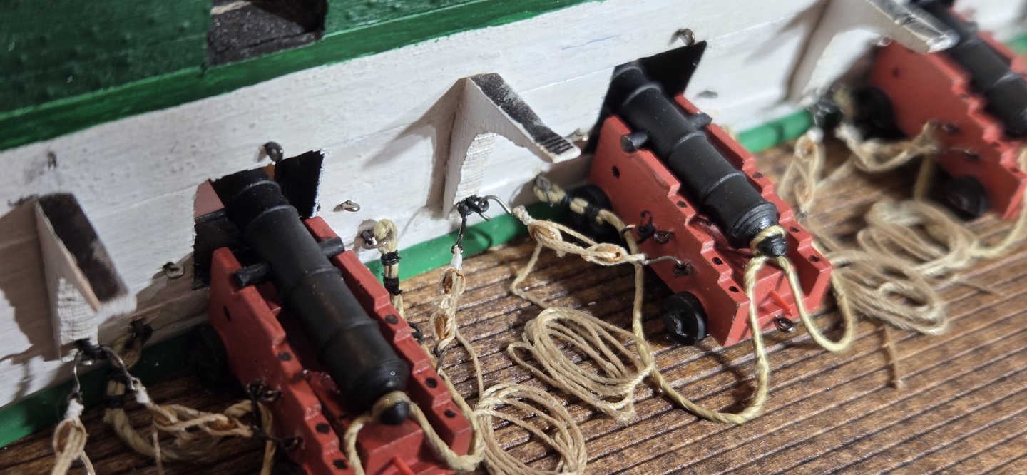
After getting a few of these put together, I started using a alligator clip to hold them so I didn't end up with a tangled mess. Also, once I got them put together, I felt the hooks, although pretty tiny, were a bit out of scale. I just have to live with that, because I don't think I could make them any smaller. For the breeching lines, I found it was much easier to put the rings and eyebolts on them first and seize the ends instead of trying to open up the rings to get them on and then trying to close them back up. After putting the rings on and seizing the ends, I attached the eyebolts to the carriages and secured the breeching line to the cascobel. With the guns assembled, they were glued into place. I had previously drilled a hole in the bottom of the carriages to accept a pin that I had inserted into the deck. To secure the carriages, I put a tiny drop of 5 minutes epoxy on the pin and the bottom of all four wheels. Once the glue had set up and the guns were secure, I attached the eyebolt on the ends to the bulwark in pre-drilled holes. Finally, the hooks on the tackles were attached to the carriages and bulwarks. Before attaching the tackles, the free ends were coiled up and the coils made secure with a miniscule amount of CA. Once all was in place, all the ropes were secured to the deck with a little CA to keep everything flat and to try to give everything a natural sag.
-
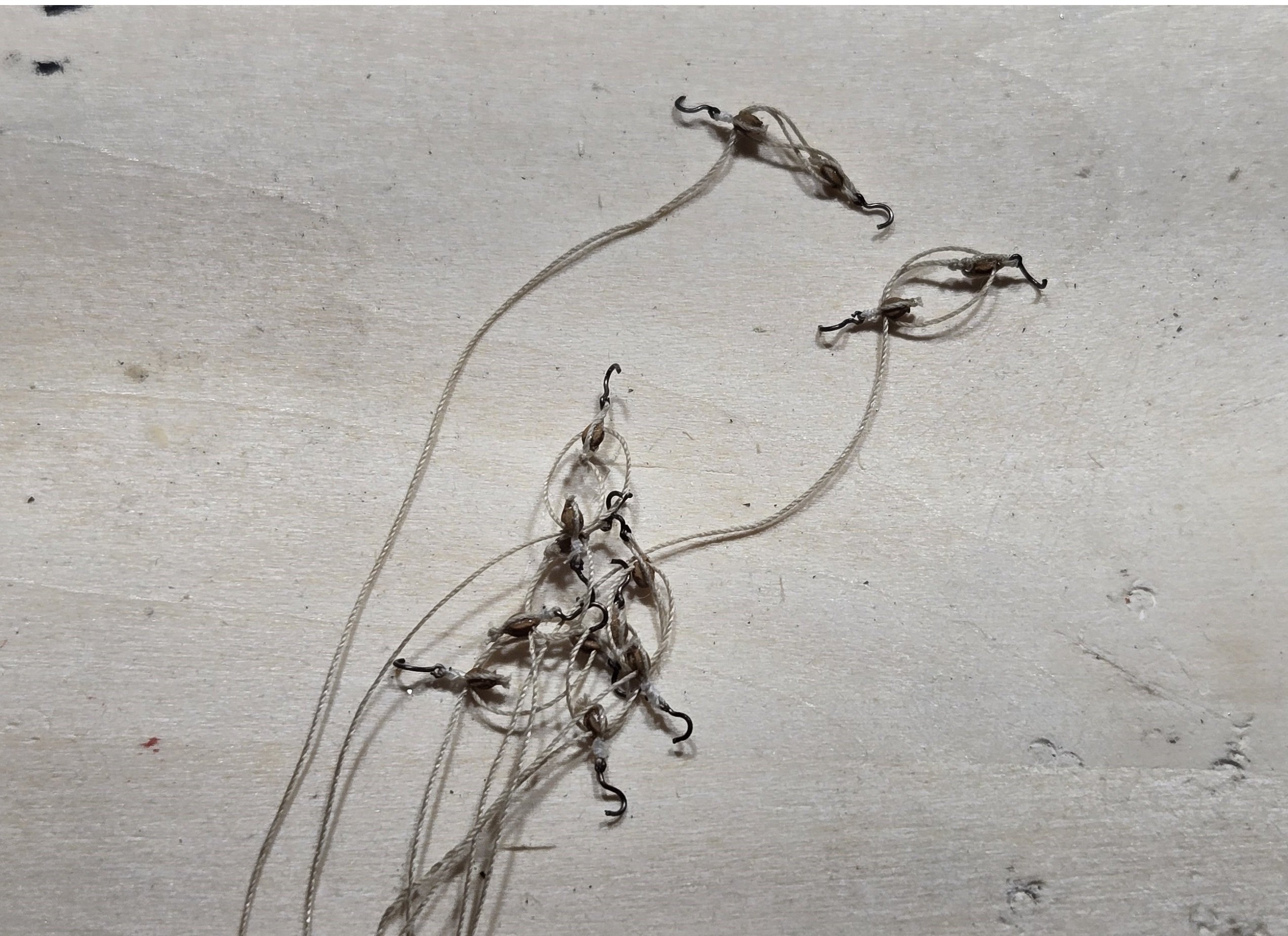
Hello All, After a long holiday hiatus, I felt it was time to get back to work, so a quick update. I've trudged along, stropping and seizing my blocks with hooks, and then assembling the tackles for the guns. I got through about 50 blocks (25 singles and 25 doubles). It's pretty tedious, and to break up the monotony, I decided to do like Jon and install a few guns on each side then work on the deck fixtures before moving further down the ship. Here's a pic of a few of the assembled tackles as I was going
-
USS Constitution by mtbediz - 1:76
g8rfan replied to mtbediz's topic in - Build logs for subjects built 1751 - 1800
I am in total awe. I can only hope to be half as good. When I do get above the spar deck, I think I may have to break down and purchase a proxxon on mill. -
g8rfan reacted to a post in a topic:
USS Constitution by Flyfisher - BlueJacket Shipcrafters - 1:96
-
Coming along nicely Jim. Good job on the catheads. I presume you used the eyebolts supplied in the kit, which are 1/32. These are definitely a bit out of scale for most of what we use them for. I've been using fly hooks, which I assume you are familiar with. Sizes 16-24 seem to be most appropriate. Just cut the shank to the appropriate length. A bit pricey here in the states, but you can buy a pack of 100 from China (Temu) for $6-8. Keep up the good work
-
g8rfan reacted to a post in a topic:
USS Constitution by mtbediz - 1:76
-
g8rfan reacted to a post in a topic:
USS Constitution by Der Alte Rentner - Model Shipways - 1/76
-
USS Constitution by mtbediz - 1:76
g8rfan replied to mtbediz's topic in - Build logs for subjects built 1751 - 1800
Mustafa, this ship looks amazing. I can only hope mine is half as good when it there -
Thanks Steve, it definitely is a challenge working at this scale.