HOLIDAY DONATION DRIVE - SUPPORT MSW - DO YOUR PART TO KEEP THIS GREAT FORUM GOING! (Only 13 donations so far - C'mon guys!)
×


Greg Davis
-
Posts
804 -
Joined
-
Last visited
Content Type
Profiles
Forums
Gallery
Events
Everything posted by Greg Davis
-
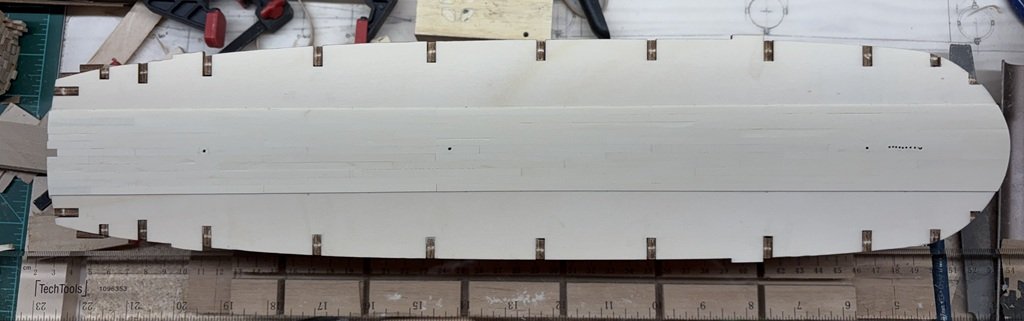
 I'm going to say the deck planking is done. Sanding with 220 grit sandpaper was followed by opening the mast and bowsprit holes in the deck. A last go over with the 220 grit and a good cleaning / dusting off prior to a thin coat of clear matte varnish. It will get another coat once the deck furniture is all in place. Bulwarks up next.
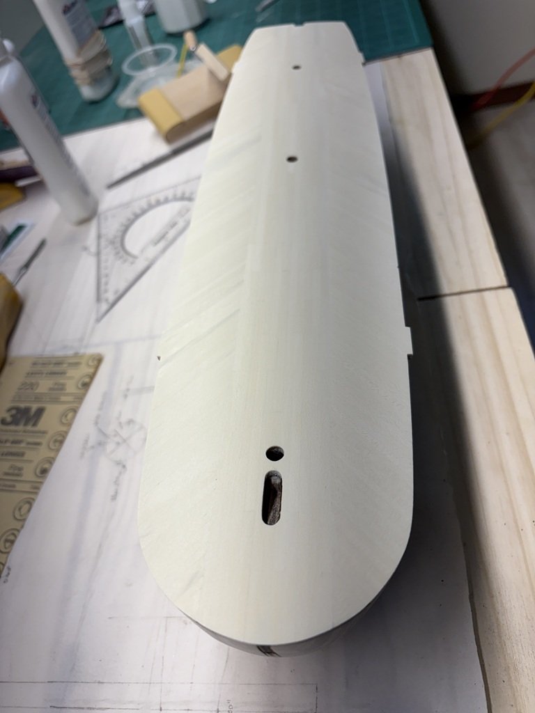
-
Keith - That is probably the best practice; however, I have just apply a thin layer and, in past projects, found that the fittings still bond very well. I tend to use white glue with a few drops of C/A when gluing to the deck for larger structures. Smaller structures are also pinned and or have recesses cut into the deck. So far (knock on wood) everything has stayed together for years! Greg
-
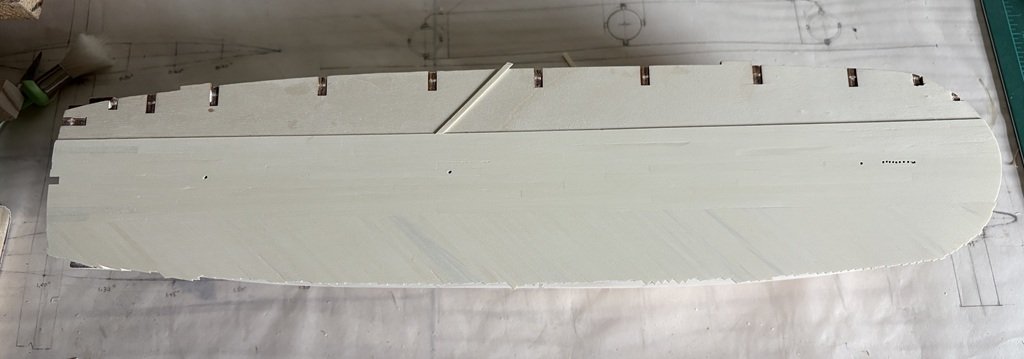
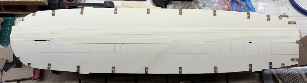
All deck planks in place and smoothed with 150 grit sandpaper. I will use at least one finer grit sandpaper to finish he surface. The I will most likely varnish the deck to give it some projection as I return to the hull's exterior.
-
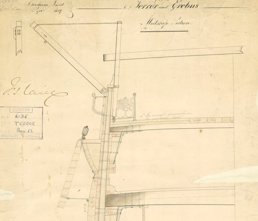
Thanks! Yes, from a physics perspective the angled planks would help distribute / reduce crushing forces from along the sides of the hull. From this cross-sectional plan it can be seen that the outer portion of the deck was planked in two layers, the top layer being set at a diagonal; the lower front to back as normal.
-
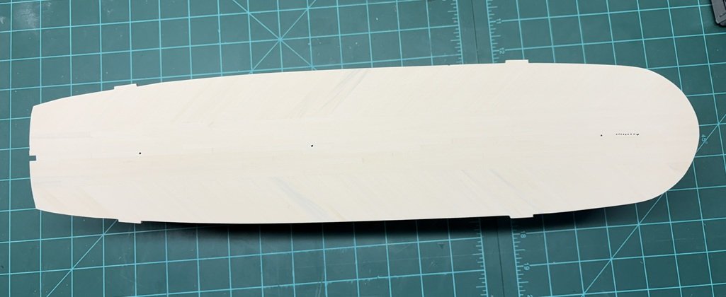
One side done as well as a bit of smoothing - a locator plank on the port side and 100+ planks to go! I wasn't sure about the color variation - client / daughter likes it, so I'm good as well! I'm going to say its icy blue.
-
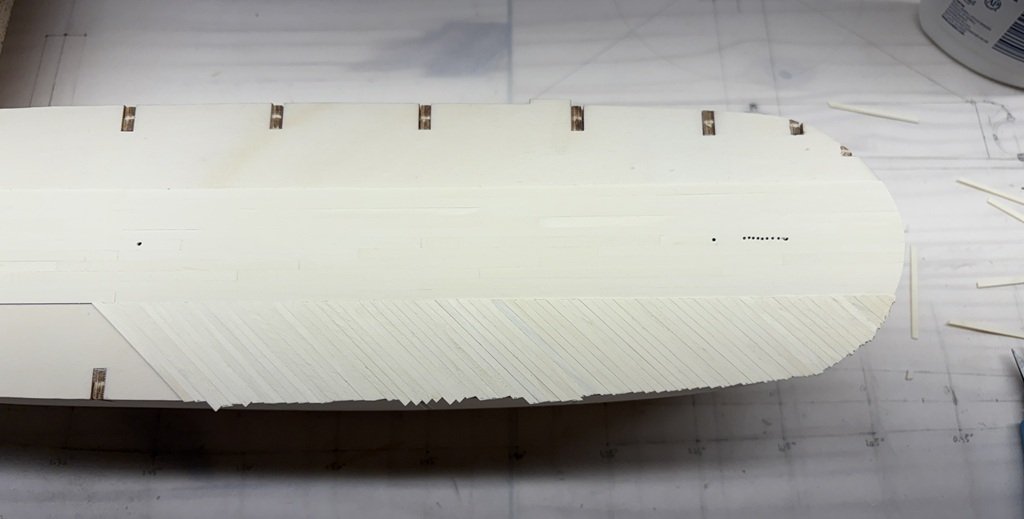
I've made it to the bow on the starboard side - about a third of the whole job done with 70 planks now in place:
-
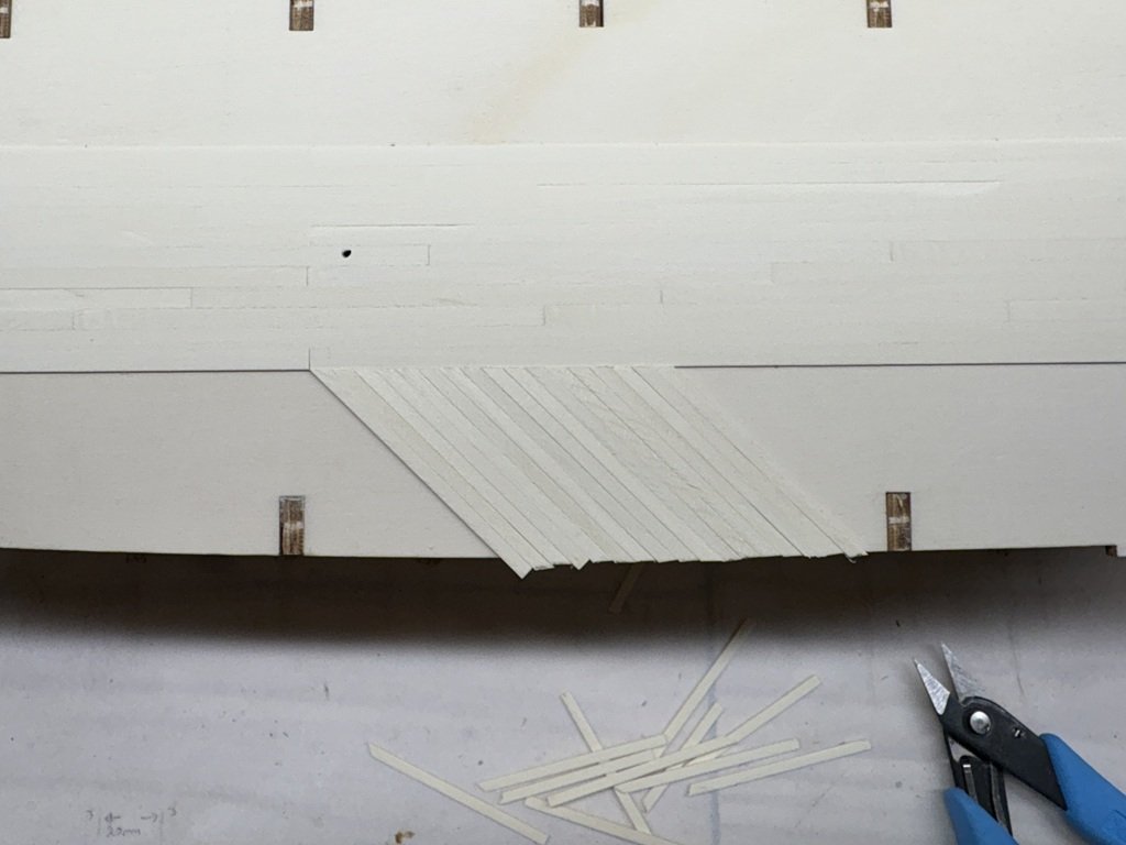
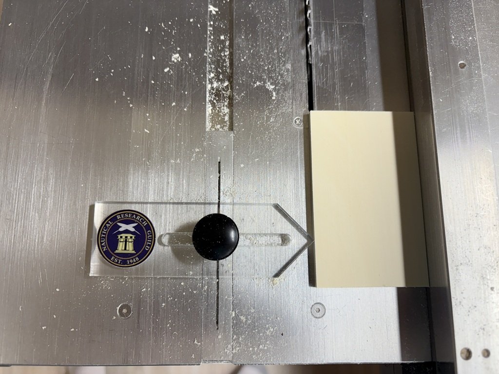
First batch of diagonal planks installed: The edge mating with the straight planks are being cut on the table saw - the rough outer edge (to be smoothed later) is being cut with the nippers as it is a little faster.
-
Very nice work! It looks like you did a great job overcoming the gaps from the first layer of planking. Greg
-
Mid-portion of deck planked. Time to make up a lot of 2.5mm wide strips for the diagonal planks - I think I counted in excess of 250 such planks on Betts' deck plan!
-
No, they're not interested in keeping water from entering the joints. But your caulking came out nicely on Beagle! Actually, I've never 'caulked' planking on any of my models. Currently, I prefer the subtle look that is generated after applying a finish to the planking, especially at the smaller scales. Similarly, I won't be using any treenails on this model. I have seen some models where caulking (and tree nailing) has been done impressively well. I would love to be able to do similar work, but at this point I don't have enough interest in this type of detail to spend the time to learn how to do it! At this point in my skill development, I am more interested in becoming more proficient with the spray gun, with the soldering unit, and miniature carving.
-
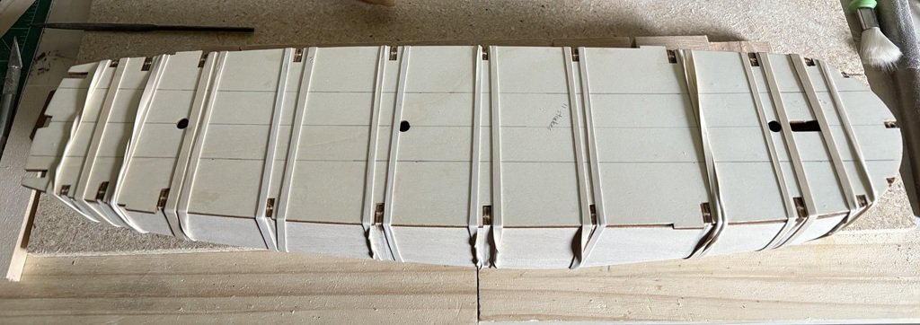
Unexpectedly workers showed up at the dockyard to begin laying the deck planking! Space for 11 strakes are being laid in a four butt shift using 8cm planks made from Holly. I'm using the NRG Thin Strip Saw Jig to cut the planks 0.7mm thick. The kit supplied planks are quoted at 0.5mm. Once the deck is sanded, the thickness should be just fine. First I tried to cut the strips using a slitting blade, but the Holly was not cutting clean (it was burning a bit) so I changed to the standard carbide blade and the work is now going well - even though I lose more wood to the blade than is in an individual plank!
-
Thanks! this version of Terror has walnut keel, etc.
-
Debated this for a bit, but decided to attach the false deck now.
-
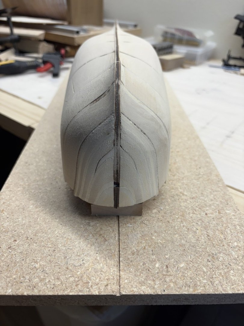
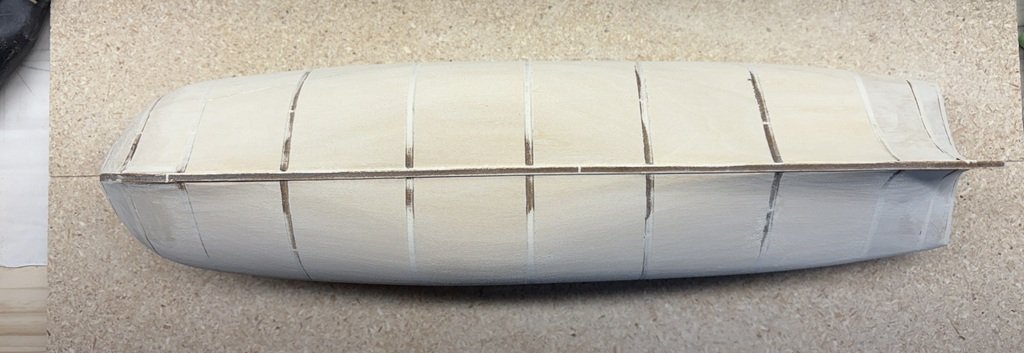
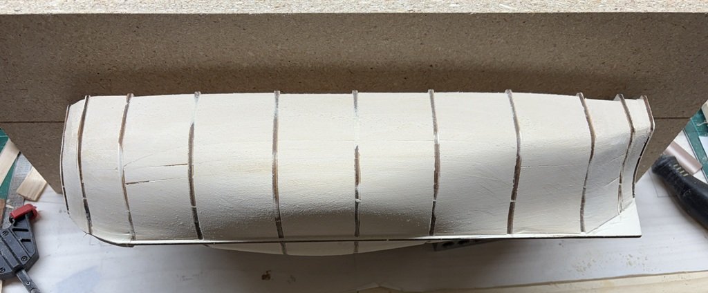
Shaping, shaping, shaping ... But progress is being made and I am now going to change from 120 grit to 180 grit in order to finish the shaping. (I started with 80 grit sandpaper.) Here are some pictures I took to help me see where there are symmetry 'issues'.

-
Too bad they didn't copy better! Is there any substantial difference between the Terror and Erebus kits?
-
Yep that’s an issue, looks like Occre cut in too fast! Am I right that the whole hull seems short compared to Betts’ model?
-
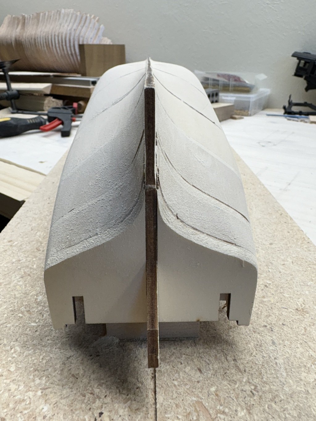
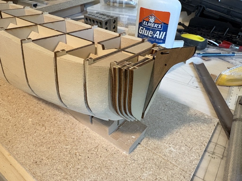
I decided to add the bow filler blocks so that I could make a nicer transition from the sides to front of the hull. In particular, I don't think I could have come close to forming the concave dip that forms on the first bulkhead. Of course this means I've taken the tack that requires this buff bow to be planked! More shaping, especially on the port side, and now very close to the profile dictated by the kit's bulkheads as I'm starting to sand off laser char most everywhere. Besides the midship bulge, there is a rough transition that needs attention near the third bulkhead from the back.
-
Thanks Keith - I will continue to study these plans and other material! Greg
-
I started the hobby not knowing anyone that could provide help or guidance. I read a lot of books, but still made a lot of mistakes. I still make mistakes when I'm not giving my full attention. One of the biggest differences now is that I have confidence to go back and fix what isn't to my liking. It still is depressing to have a setback, but it is not as depressing as it once was. I think there is some truth to learning from one's mistakes and/or working thru issues that arise to find alternative ways to complete a modeling task. The Mamoli HMS Beagle kit was my first experience with wooden ship modeling. I got stuck a lot of times on that model. In fact, I shelved it a few time and started / finished a couple of other models before 'completing' Beagle. Occre's version seems much nicer and closer aligned to what the ship probably looked like in reality. I think you have made a good but sightly challenging choice for your second(?) model. Have you had a chance to read the Conway publication 'Anatomy of The Ship HMS Beagle'? While it could send you down a rabbit hole, this may be one of the best books related to the ship itself and was likely used as a reference when the Occre model was developed, thereby superseding the Mamoli model that is a poor resemblance! I now go back and forth between kits and scratch building. In many cases, I find scratch building to be easier in the sense that I don't feel compelled to make the kit provided pieces / material work. I hope you keep at it, the learning curve can be steep at times but fellow modelers will often provide guidance and on this site are almost always positive / supportive when an issue develops. With that said, if there comes a time where you are looking for input but don't feel comfortable posting for all to see, feel free to PM if you like.
-
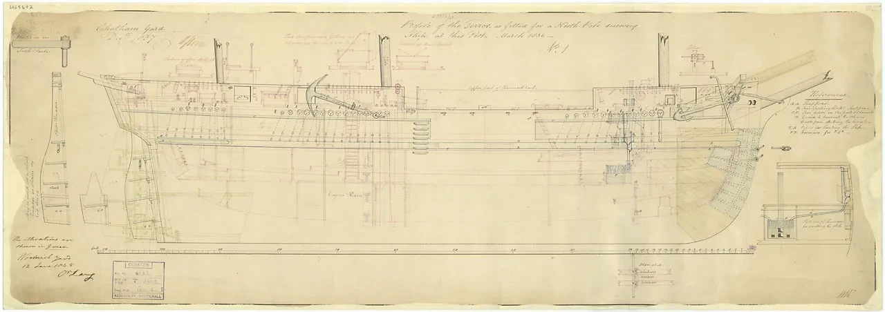
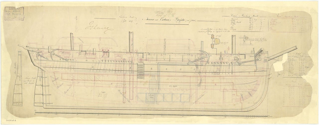
So you are (partially) referring to these draughts? Before screw added: After screw added / bowsprit moved: By chance have you read: I found the first appendix of this volume interesting, I assume similar work was done for preparing Terror at this time:


-
Yes, it would be just the forward portion. Maybe add a few bulkhead doublers to form a better base/support for gluing the new planks. This area is hard to plank with the straight planks included in the kit. Wood strips do not like to bend in as many directions as needed up front. If you replace and use the same provided material consider cutting new pieces to approximately the correct shape, soaking them in water so they become more flexible, pinning them to the hull to get the correct bends, letting the piece dry before taking off, finish shaping, and then permanently attach. This should provide a more satisfactory under-planking. If you give this a try, and you haven't come across the topic yet, when planks are drying / your having building downtime consider checking out how planks can be 'splied' to provide a very nice fit when bent around the bow.
-
You may run into some problems in the region that displays a gap on the far left of the picture above. Here it looks like the strake above doesn't overlap the stake below. When you sand this out a couple of things may happen - there might be a bigger gap and/or the remaining surface, even after using filler, could be extremely thin. You may not have a good foundation for your second planking. Gaps where the two planks form a more continuous surface won't be structurally as much a problem. Some would recommend that you detach planks in the offending regions and then re-plank. It does take courage to do that, but if the filling / sanding does not prove satisfactory, this may be a possible solution. There may be a possibility to drill a hole between the bulkheads where the planking is problematic and then spay in a bit of an expanding foam filler; I think I saw someone do something similar (or I may be making it up!). Getting the right amount shot in would be tricky - when I've used this type of material for home repair / maintenance these products always seem to expand more than I expect! But if you get in the right amount and then start sanding, the foam could form a reinforcement to your planking from behind and help form a more solid surface for the second planking. Either way, if you keep at it I'm sure you'll get the save Greg
-
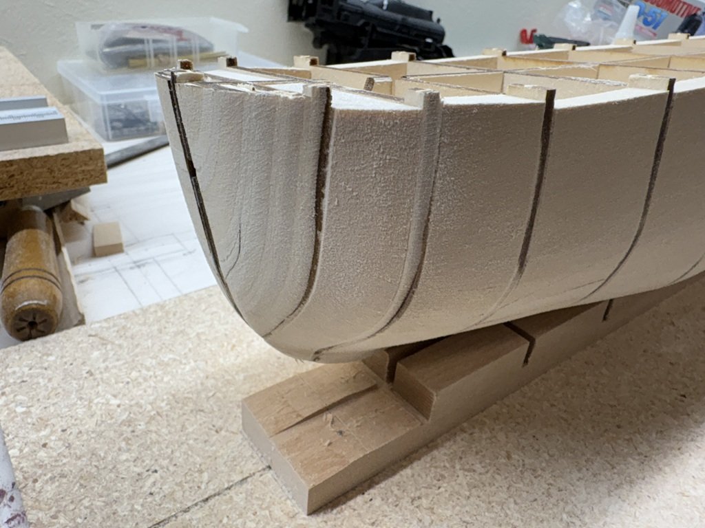
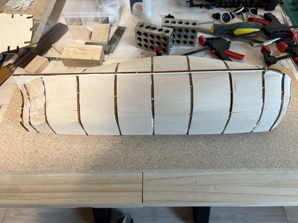
I've been spending a good deal of time each day (at least a couple of hours) shaping the filler blocks. Slow going! I'm finally getting close / starting to bevel the bulkheads. So the extreme fullness of the model has not been addressed yet. In this picture, I don't like the way the lower hull aft changes from convex to concave. Hopefully this will become a more graceful transition as the work continues. I have the Palin book on order - it is suppose to arrive tomorrow. Right now I'm interested in learning more about Terror's time during the Ross expedition in the Antarctic. Antarctic expeditions have been always more interesting to me than those in the Artic. In fact, I am considering portraying my model closer to that time period - i.e., before the modifications such as the addition of the screw present on the Franklin expedition. From what I currently understand, this would have me installing a different shaped rudder and giving me the opportunity to copper the hull. The latter is inviting to me! Plenty of time to ponder this as the shaping process continues.
-
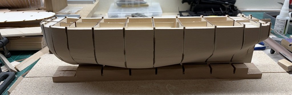
Did some more hull smoothing and now have added fillers to the remaining 3 spaces defined by the bulkheads. Quite a 'buff' bow on this one and a quick transition aft from the full mid-section. I would guess that Terror was not a fast sailing ship!
-
Using filler blocks is not uncommon. They are very often used near the stem and stern on plank on bulkhead models - places where there is a good deal of changing curvature on the hull. When preparing the hull for planking, the filler blocks can help define the shape of the finished hull. As, or perhaps more importantly, the filler blocks then provide a larger gluing surface for the hull planks. I think you very well identified some of these issues in one of your posts (#4) about your experience building the Polaris kit. For this model I've chosen to use filler blocks to help shape the hull envelope as well as to deal with alignment of the bulkheads / false keel. Some kits do a better job in terms of more closely spaced bulkheads and stiffer material and/or additional lengthwise wood inserts that keep the structure closer to true. (Some builders fabricate and add additional bulkheads between the bulkheads provided in a given kit.) The Terror model is quite flexy as designed so the blocks make it more rigid. It does take time to fit the blocks and then to shape them, but the tradeoff in an easier / nicer planking job can be expected. Still one needs to be careful in how the work is done - I hope you read some of the earlier posts in this build on how I made a royal mess out of the model when I wasn't paying attention to what I was doing! The first several plank on bulkhead models I made did not have much in the way of filler blocks, but I have used them for the whole hull in the last 5 or 6 plank on bulkhead models I have made. There are times during the hull shaping / sanding process that I question myself about the time and dust involved during this step, but when I get to planking I am always happy I did the underlaying work. Additionally, I actually like the extra weight the hull / model takes on from the added wood. By the way, quite a fine job on your first model! Perhaps you could try filling a few regions in you next model to see how the process works and determine if the method would be one that is helpful for you. I'm sure you have already noticed that collectively model ship builders often have many methods for achieving / working toward the same type of outcomes. What works for one person may or may not work for others. But if you have the time / energy to try different methods you may be able to add to your modeling skill toolbox. Happy modeling and I do hope you start a log for your Beagle model. Greg