Greg Davis
-
Posts
807 -
Joined
-
Last visited
Content Type
Profiles
Forums
Gallery
Events
Everything posted by Greg Davis
-
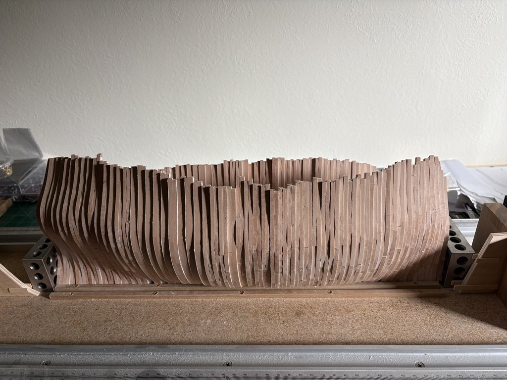
 Here are all the full frames together - I think there is an unwritten rule that they need to be stacked up and photographed at this point:
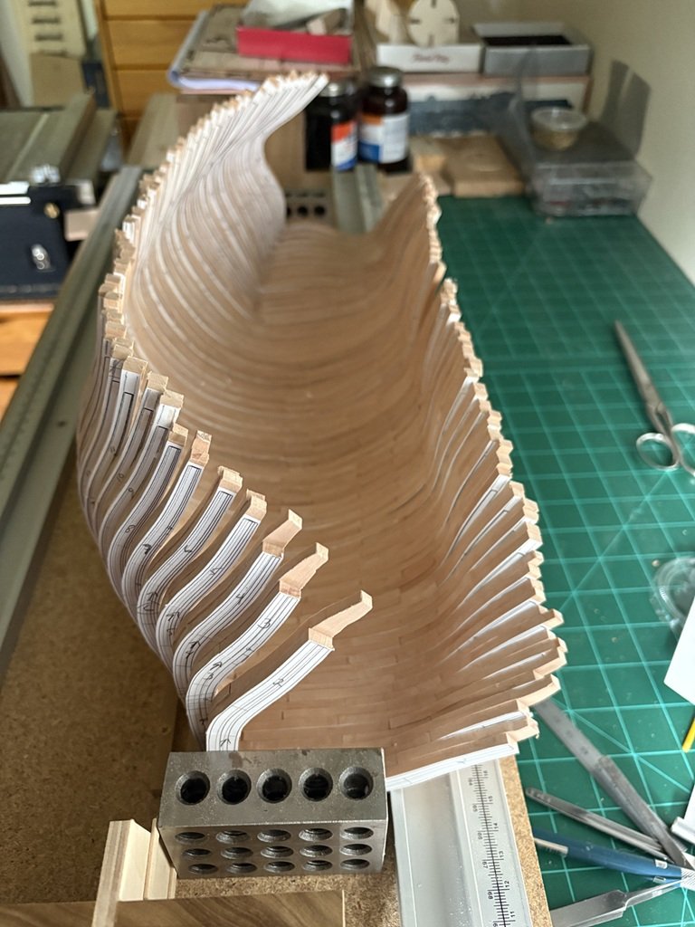
-
Thanks for dropping in, the complement, and for making your very nice build known to me! Greg
-
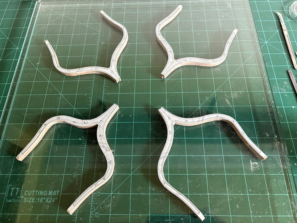
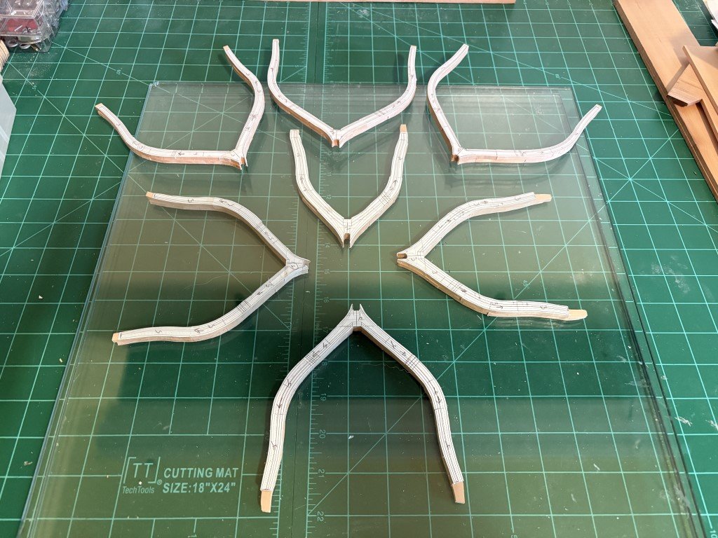
Here are the last 4 full frames glued up and drying between glass plates. Time to build a keel to set the 55 full frames on!
-
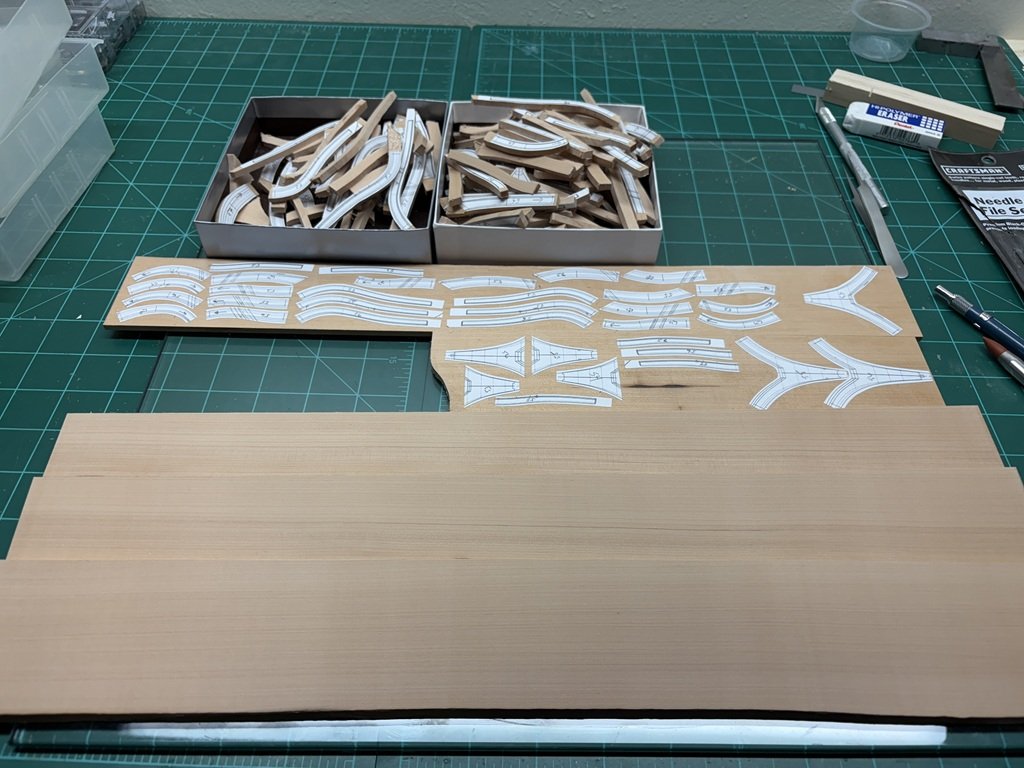
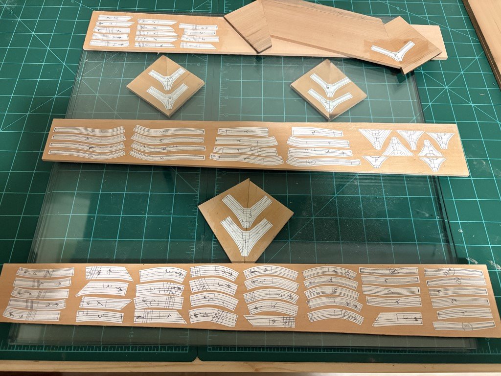
A bit more progress - two more sheets of parts to cut out and I will have 180 pieces needed to assemble frames 43 thru 57. The three sheets of wood in the foreground are 5.35mm thick - they are for the next phase: the keel structure.
-
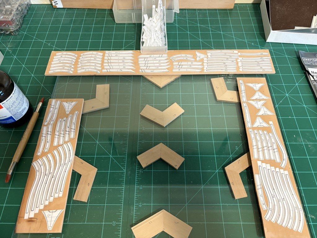
Most of the parts for frames 43- 50 are ready to cut out. Blanks for the two part floors are between glass plates drying flat. Photocopied patterns for all the parts for frames 51 - 57 are in the plastic tray ready to be rubber cemented to wood. I feel I'm getting rather proficient with the frame assembly line! Looks like I also need to prepare a bit more 4mm thick material for the last 7 full frames - not going to make it with what I've already milled.
-
Frames 2 - 8 assembled. So frames 2 - 42 have been put together. I've made (a lot of) photocopies and am preently cutting out the patterns for the remaining full frame.
-
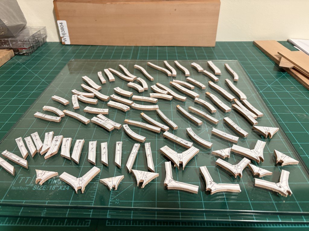
Good deal of time at the scroll saw, followed by trimming ends on the Byrnes table saw, and milling of the slots for attaching to keel. So now I have a 'kit' for frames 2 - 8 to assemble! I think 3 or 4 frames fit between my glass sheets for drying, so 2 - 3 days of work with these. Simultaneously, I can start building a kit for Type C frames 43 - 57. After that, it looks like I better get at the keel structure and make a building board / cradle for L' Invention. I am really looking forward to seeing the frames standing up in order giving a first impression of the hull shape!
-
First batch of Type C frame pieces are ready to go to the scroll saw. These pieces will make up frames 2 to 8; the remaining C frames are 43 - 57. Once done, I believe that will be all of the full frames - 56 in total.
-
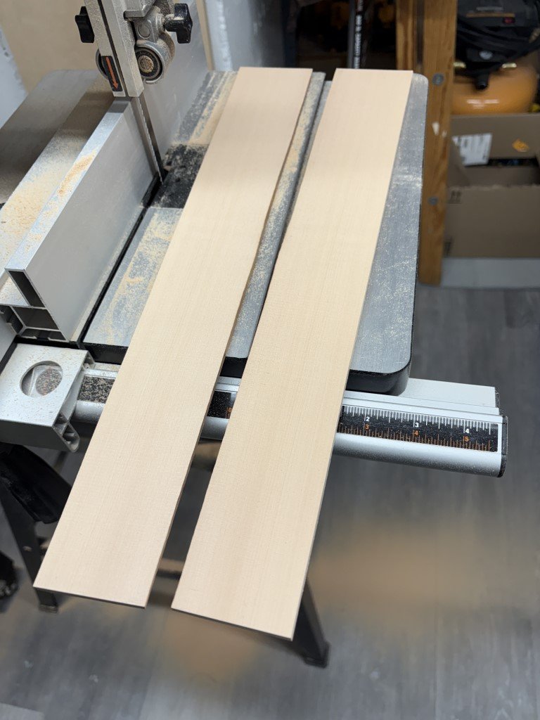
I know it has been quite a while - much longer than expected! The 'quick diversion' of building the Santos-Dumont 14bis turned into researching and building a model of the Santos-Dumont No 18 Hydroplane. But that is done and today I got out the Swiss Pear and started to mill enough wood to finish the remaining frames. Looking forward to making frames and then a keel structure to place them on!
-
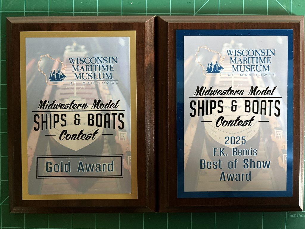
First, I want to say thank you to everyone that spent time following this build and an especially big thanks for all that provided me with their views and information that I would not have otherwise been knowledgeable of. Second, I have gotten back home from an enjoyable couple of days at the 48th Midwestern Model Ship and Boat Competition. This morning, I was quite satisfied to see the model had earned a gold award in the advanced category; but later in the day, things got even better when it was announced that the Santos-Dumont No 18 Hydroplane had been judged as Best of Show!
- 288 replies
-
- 9
-

-

-
- Santos Dumont No. 18
- hydroplane
- (and 1 more)
-
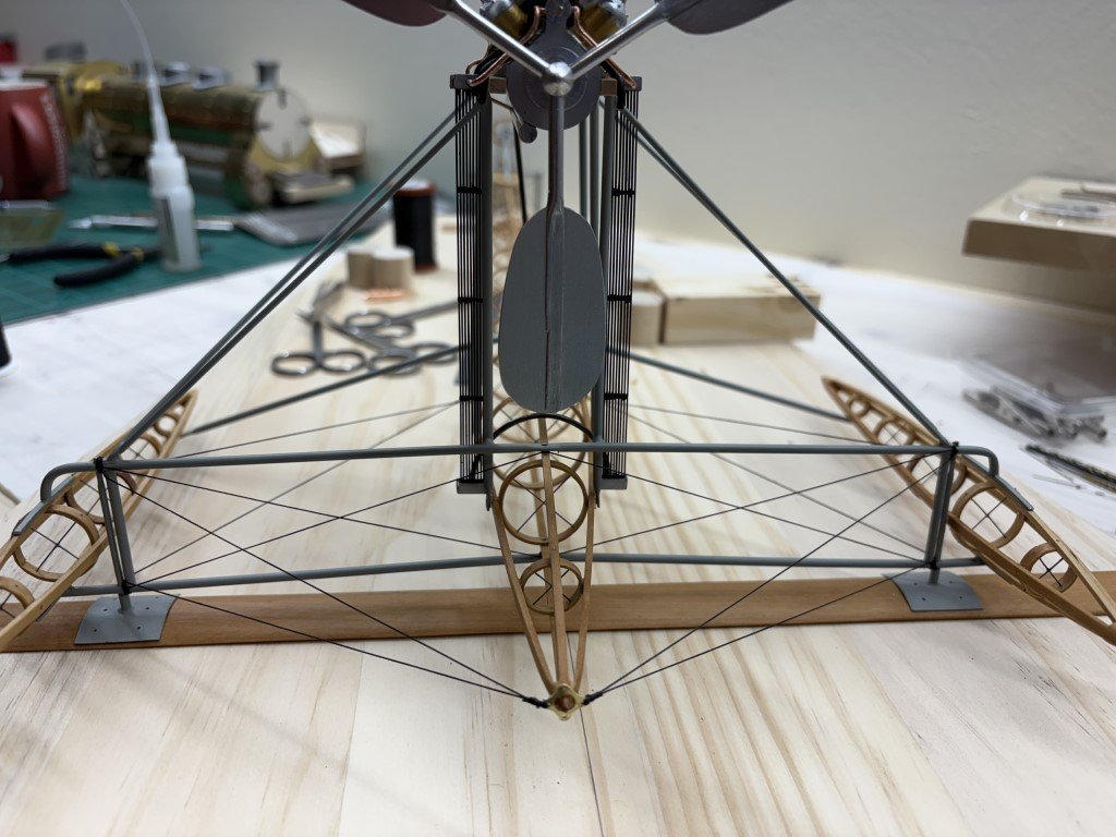
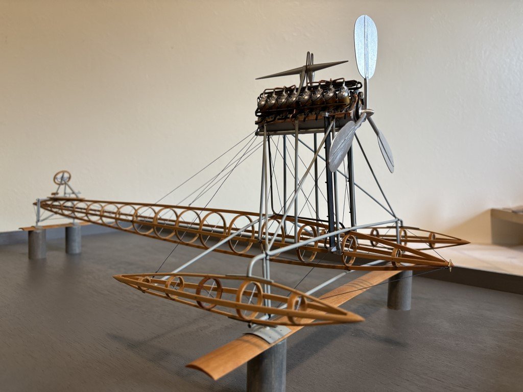
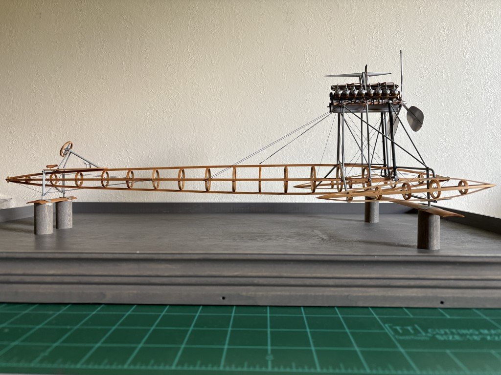
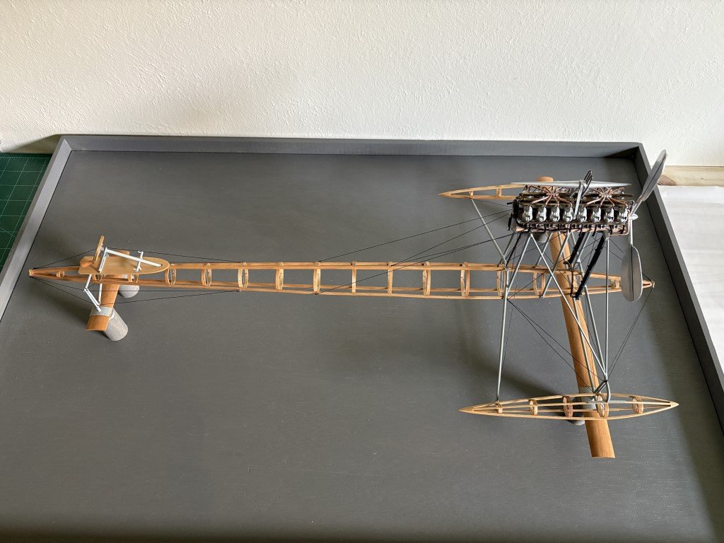
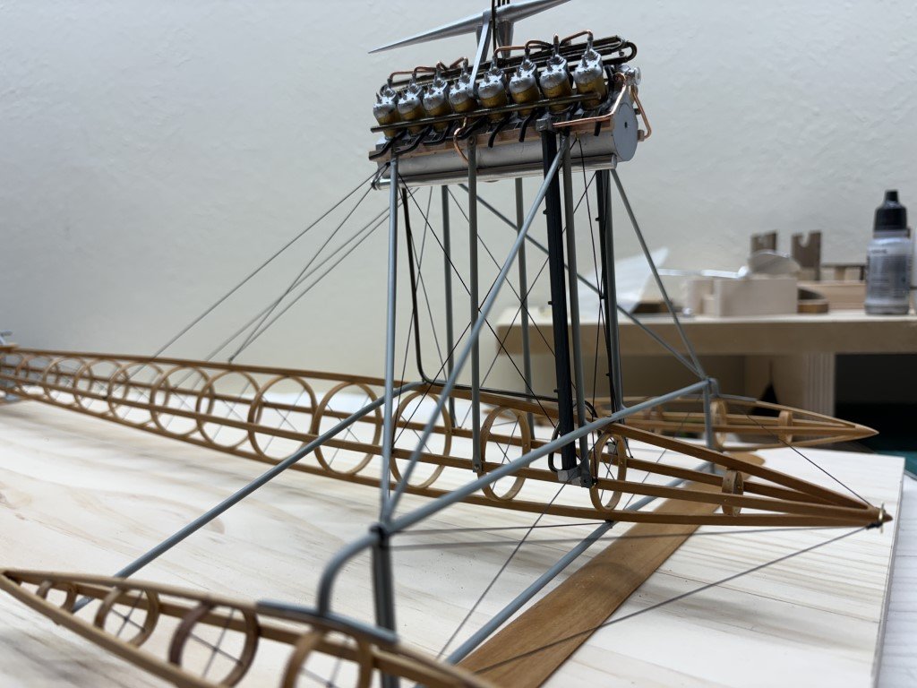
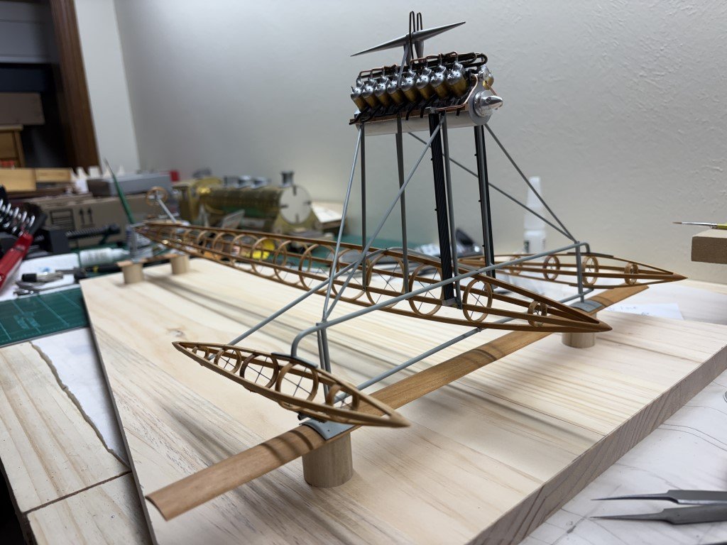
The model mounted on a display board now. I'm not sure I will add more to the model at this point; however, if 'new' information appears I am not opposed to modifying what has been done to this point. Friday the Santos-Dumont No 18 hydroplane will get a ride to the 48th Annual Midwestern Model Ship and Boat Contest. Very interested in what kind of feedback I will receive - hope it is liked!
- 288 replies
-
- 17
-
-
-
- Santos Dumont No. 18
- hydroplane
- (and 1 more)
-
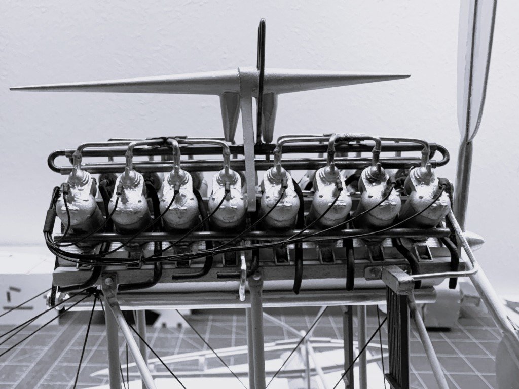
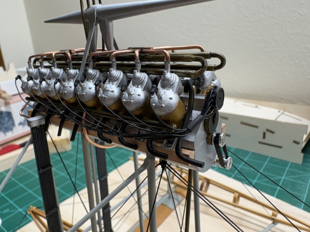
All ignition wires are in place and I believe I have done what I can wrt the engine. All the woodwork for the case has been completed. Staining / finishing and then model installation followed by a couple of final details; however, for the most part I think I'm close to a finished (for now) situation.
- 288 replies
-
- 8
-
-
- Santos Dumont No. 18
- hydroplane
- (and 1 more)
-
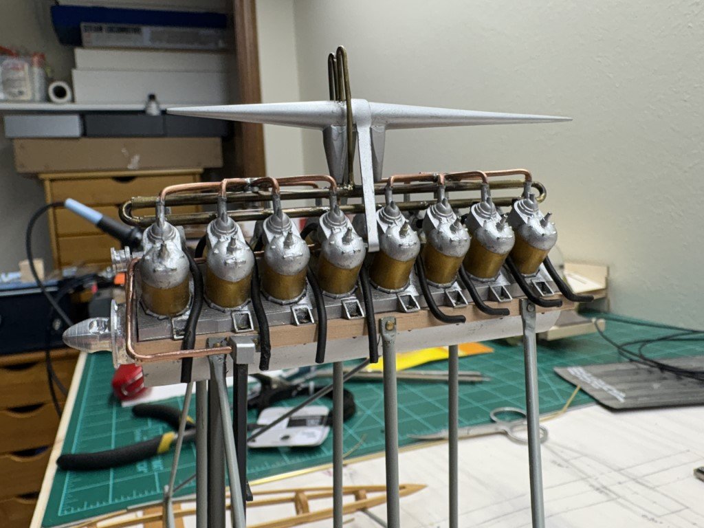
As I went to the other side, more boots went missing so I ordered more as a safety measure - it must of worked because a got 16 in place and have one left over before receiving the extras! I've wired one side based on the following picture: Here's the result: Time to turn the boat around and complete the wiring.
- 288 replies
-
- 9
-
-
-
- Santos Dumont No. 18
- hydroplane
- (and 1 more)
-
Rigging is done (as far as it's going to be!). So on to the ignition harness. Trying to install resin spark plug boots; they're a bit of a challenge for me and I've lost two to my gray floor so far - lucky I ordered 20, 8 on -2 lost is a ratio that will work. The boots are made by Pro Tech and are marketed for 1/25 scale model cars.
- 288 replies
-
- 6
-
-
- Santos Dumont No. 18
- hydroplane
- (and 1 more)
-
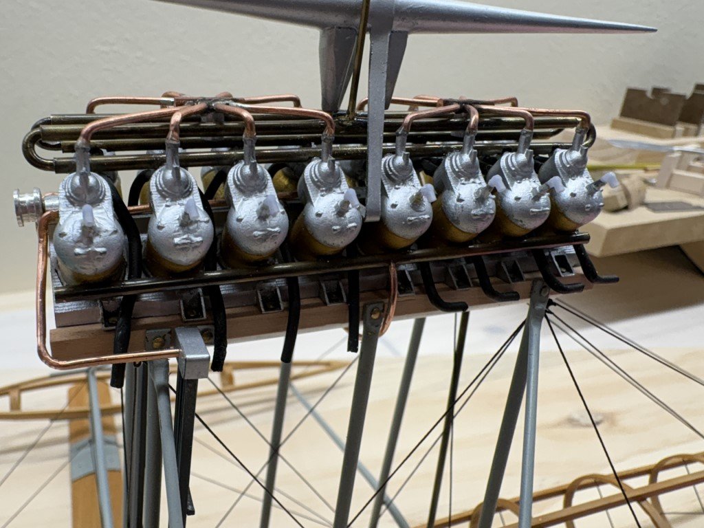
Even tighter now! Added the engine pylon bracing and backstays: Two more lines to go; the one's that go from engine pylon to aft part of the nacelles. Then onto the ignition harness to finish what I plan to do on the engine.
- 288 replies
-
- 7
-
-
- Santos Dumont No. 18
- hydroplane
- (and 1 more)
-
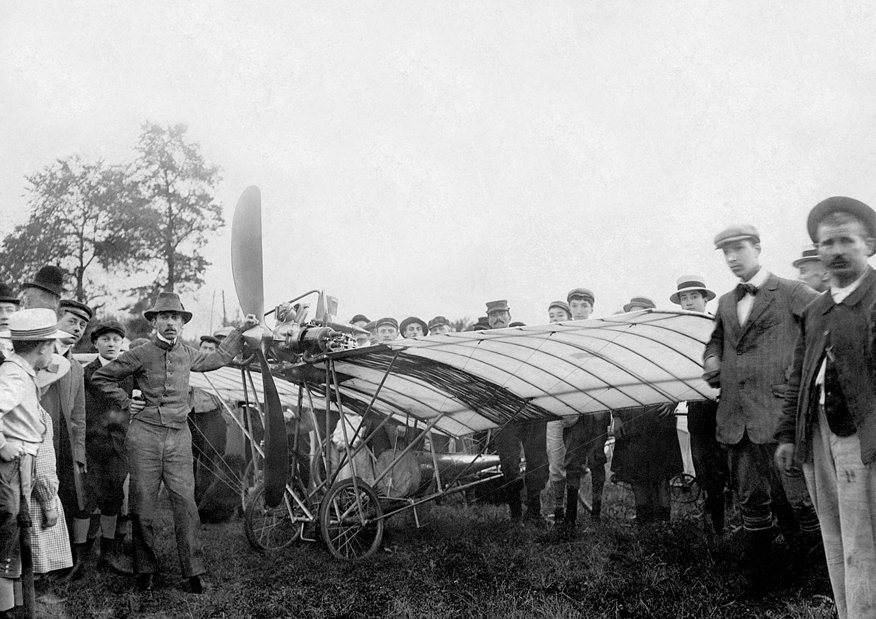
I need to keep reminding myself that his contraptions were almost always in flux and that he seemed to like having pictures taken with his work no matter the stage of construction. Combine this with him taking parts from one project to put on another and then possibly modifing after in place makes using the photographic evidence so much fun!
- 288 replies
-
- 2
-
-
- Santos Dumont No. 18
- hydroplane
- (and 1 more)
-
What is the conical structure behind the pilot seat on the No20? Could that be fuel and the double cone on top just coolant? I like the radiator piping along the wing panels!
- 288 replies
-
- 1
-
-
- Santos Dumont No. 18
- hydroplane
- (and 1 more)
-
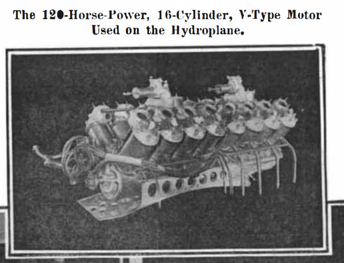
Here's a picture that came from an October 19, 1907 Scientific American article where the intake spider is not in place, but you can see the carburetors. I guess one would need to be reversed to accept fuel from the tank funnel that is between the two carburetors on Santos-Dumont's No 18 set-up.
- 288 replies
-
- 1
-
-
- Santos Dumont No. 18
- hydroplane
- (and 1 more)
-
You are right - space is tight, but I did include use couple of pieces of aluminum under the spiders to represent the carburetors!
- 288 replies
-
- 4
-
-
- Santos Dumont No. 18
- hydroplane
- (and 1 more)
-
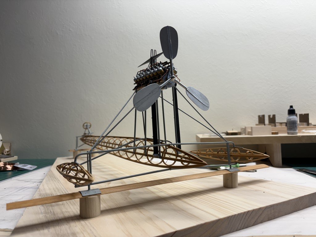
Here's what the model looks like with the propeller unit in place: Return piping for the coolant to make it back from the radiators was also added today. I'm waiting on some resin spark plug boots to see if they will make the ignition harness wiring look better than what I could do on my 14bis model. Then some rigging...
- 288 replies
-
- 5
-
-
- Santos Dumont No. 18
- hydroplane
- (and 1 more)
-
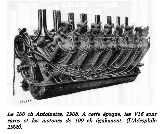
Thanks for sharing - this looks like a later model than was used by Santos-Dumont on the 14bis. Those copper water jackets must have been a joy to produce! Also, quite a different air intake than the 'spider' version!
- 288 replies
-
- 1
-
-
- Santos Dumont No. 18
- hydroplane
- (and 1 more)
-
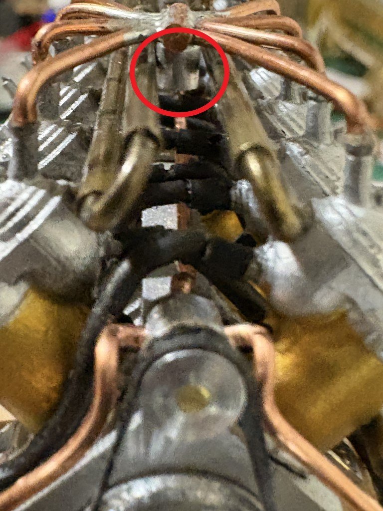
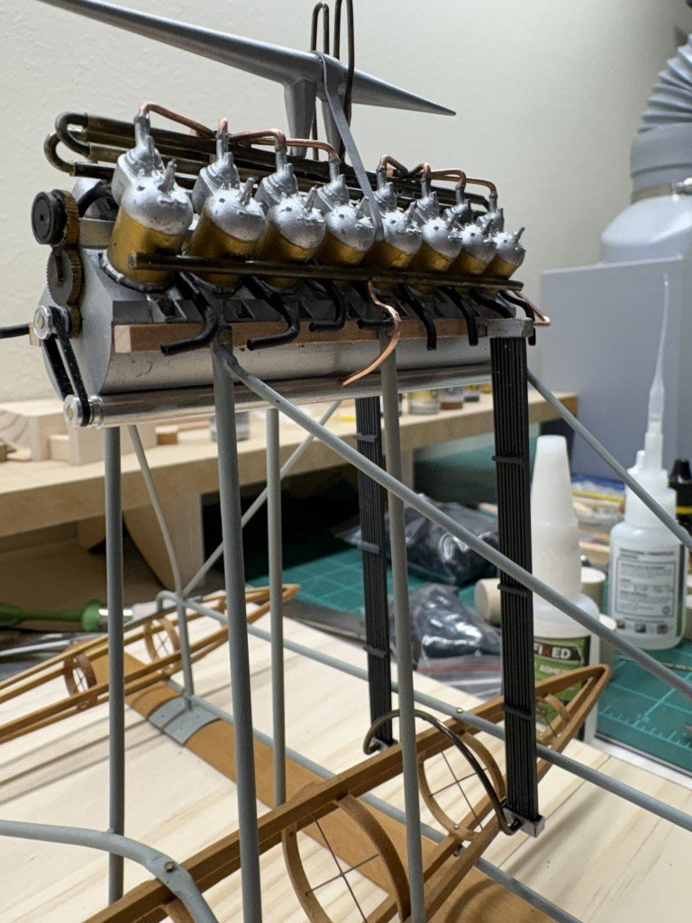
More engine work today - added the coolant intake manifolds and the lower coolant pump together with the connections between the two. I'm using one of the castings from the Model Airways engine kit for the magneto and associated gearing. I've drilled 16 holes into the magneto to accept the ignition wires. I also added the lower half-round connection between the radiators. Besides installing the ignition harness and adding some piping from the lower radiator connection going back and up to the engine, I think this will be the end of the propulsion system (short of installing the propeller). I think I'm now at the limit of what I can reasonably do on this part of the model. Some rigging will be coming soon to wrap the project up for now - at least until additional relevant information on the Santos-Dumont No18 Hydroplane surfaces! P.S. Yesterday's requested side project:
- 288 replies
-
- 8
-
-
- Santos Dumont No. 18
- hydroplane
- (and 1 more)
-
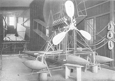
All the exhaust pipes are in place. The next big project will be getting coolant intake piping / etc. in place. As a small diversion I have started building a case for the model. I've cut this trapezoidal piece of wood to serve as a base board / raise the model up a bit. For the final presentation, I am looking for something remininsent of the picture of the No 18 that was taken in Santos-Dumont's workshop:
- 288 replies
-
- 11
-
-
- Santos Dumont No. 18
- hydroplane
- (and 1 more)
-
Thanks for the encouragement! Definitely going to see this through - the finish is in sight. Half of the remaining exhaust pipes formed and in place:
- 288 replies
-
- 8
-
-
- Santos Dumont No. 18
- hydroplane
- (and 1 more)