HOLIDAY DONATION DRIVE - SUPPORT MSW - DO YOUR PART TO KEEP THIS GREAT FORUM GOING! (Only 13 donations so far - C'mon guys!)
×


Greg Davis
-
Posts
804 -
Joined
-
Last visited
Content Type
Profiles
Forums
Gallery
Events
Everything posted by Greg Davis
-
 It's been a while since I worked on this model, but today I got back at it! Cutting copper plates - several hundred so far. The Dspiae cutter does a great job, I'm just wondering how long the blade will hold up. unfortunately, The blade appears to be proprietary (and expensive). Soon I will start attaching to the hull.
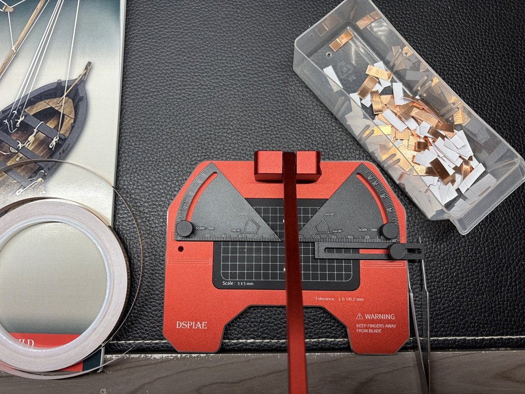
-
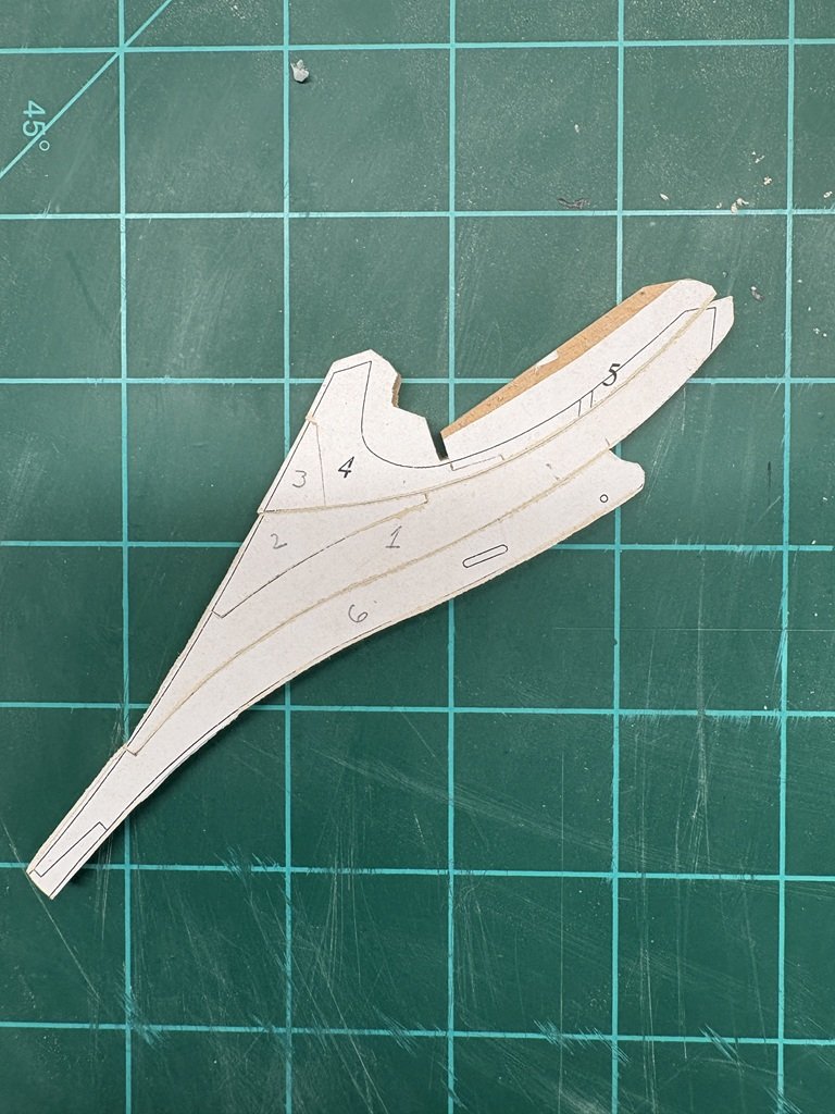
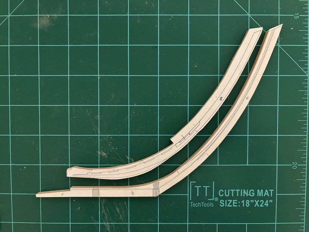
Another day, another joint! This will sit between glass plates through the night to insure it dries flat. I can then remove some of the excess material along the curved contour of 4 and 5. The flat on the top of 4 will be cut a bit later so that it matches the top of the stem. It also looks like I can start working on the joint between what is done and the stem.
-
It looks wonderful - feel free to hijack at will! Thank you so much for the complement on my work; it means a lot to me. Greg
-
A few more parts connected (3, 4, and 5) together today. 4 and particularly 5 are delicate; this is why I left quite a lot of material on the top for now. Once the bottom is matched to the surface of parts 1 and 2, I will go about removing material / shaping the top contour.
-
Is this South Carolina?
-
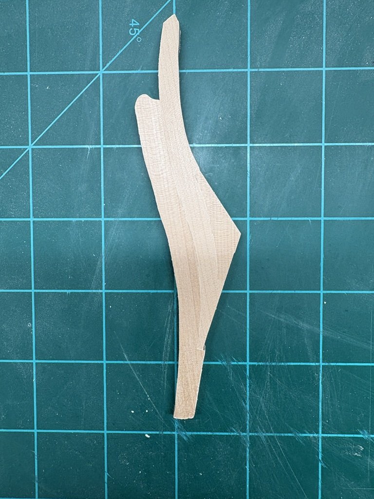
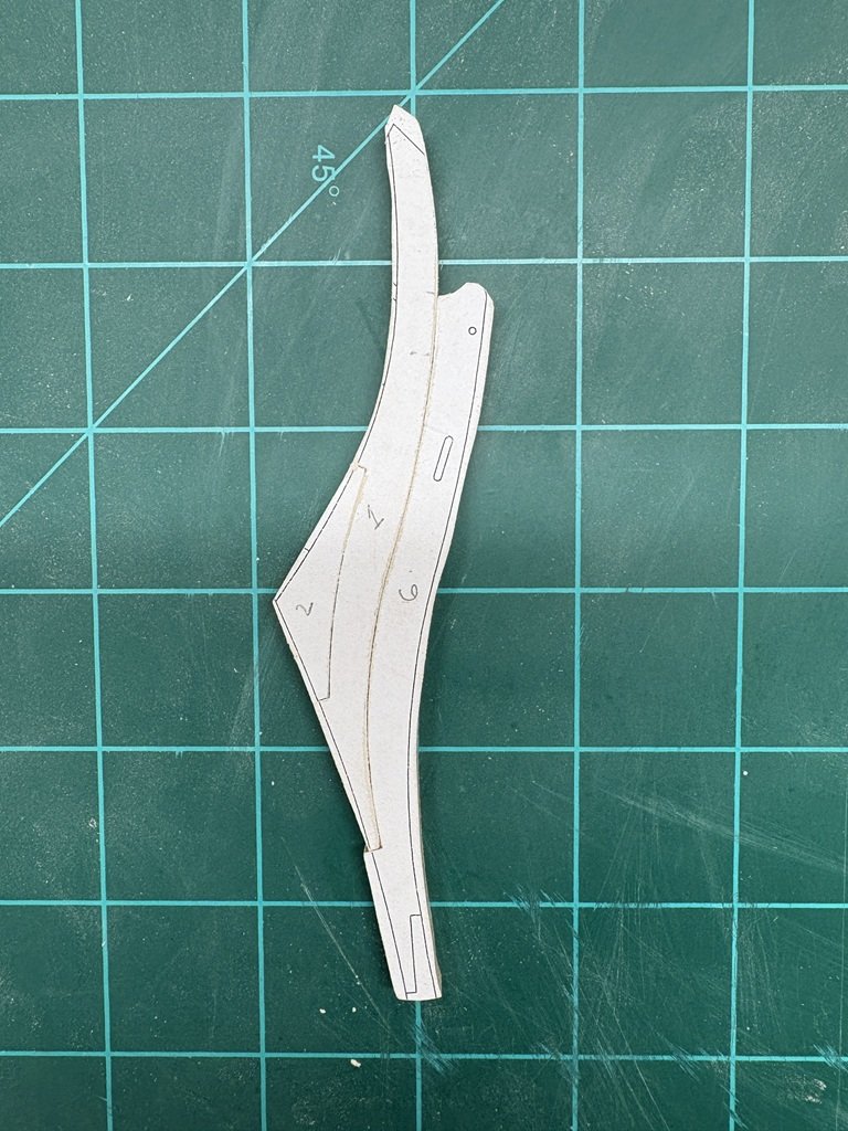
As I was cleaning up the outer profiles I was really pleased to see the thin perpendicular line indicating the joint between pieces 1 and 2. While this will soon be covered by another piece, it is gratifying to see the joint is tight front to back!
-
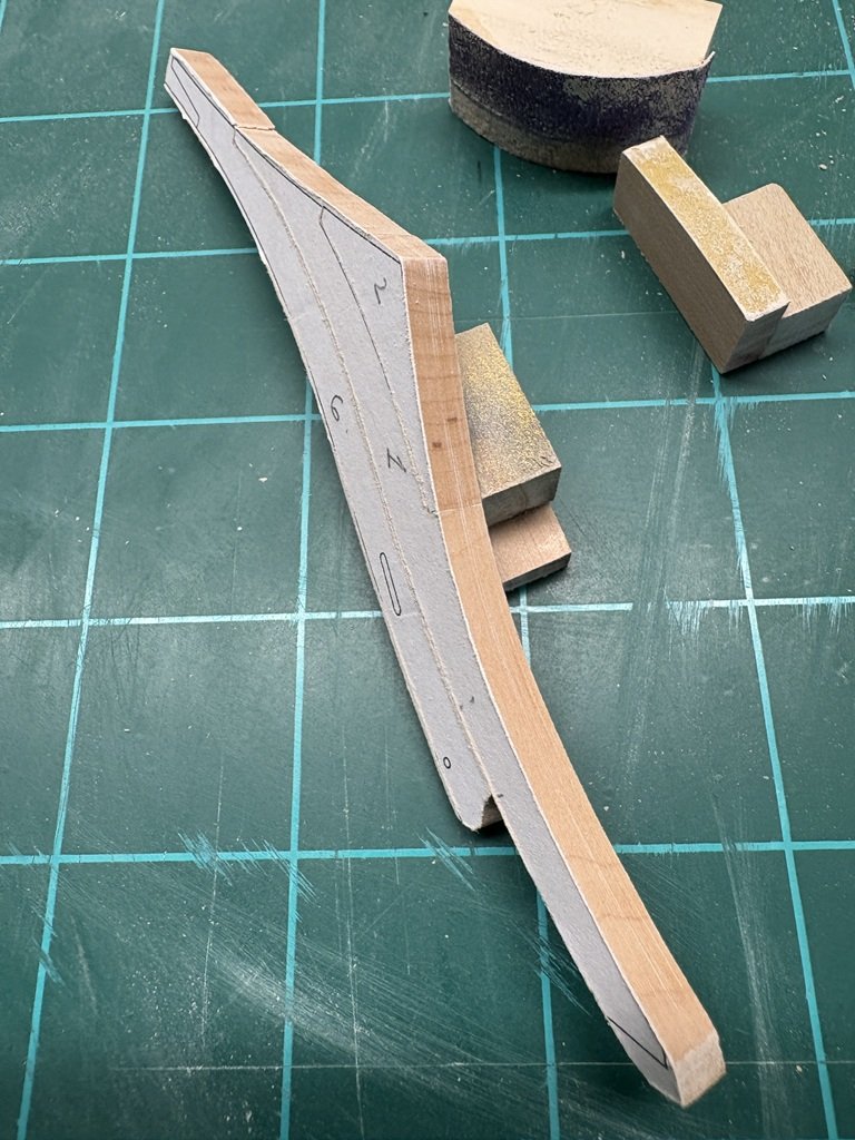
First three parts of the assembly are in place. Joining parts 1 and 2 was challenging due to the curved shape together with the fact that 2 drops into 1. The joint between 1 and 6 is LONG! This is what the joints look like from behind:
-
I will definitively be string the structure in a safe place after building it and then attach the cutwater / head once the hull has been planked. Thanks for the input / direction! Greg
-
Thank you for the proper vocabulary! Greg
-
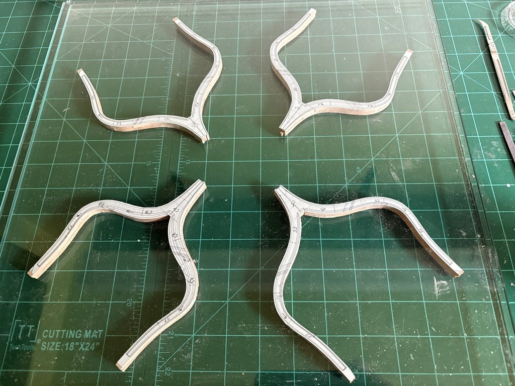
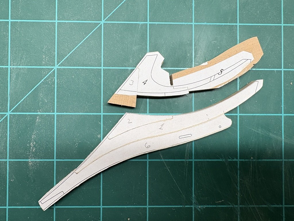
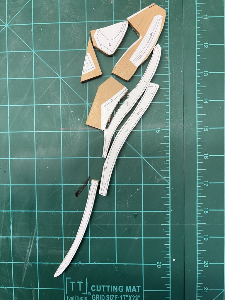
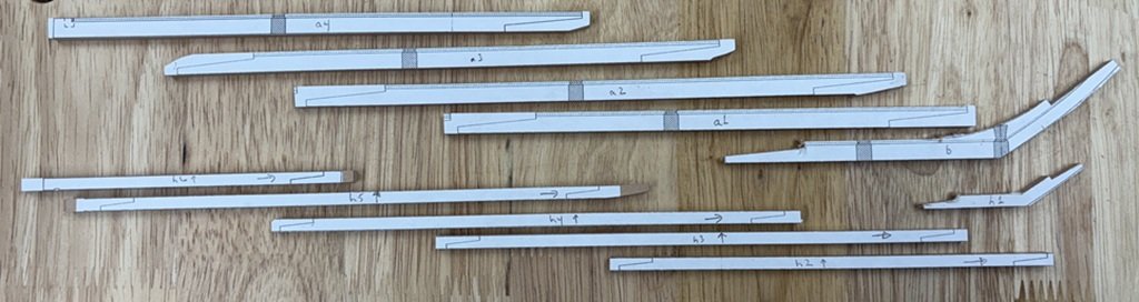
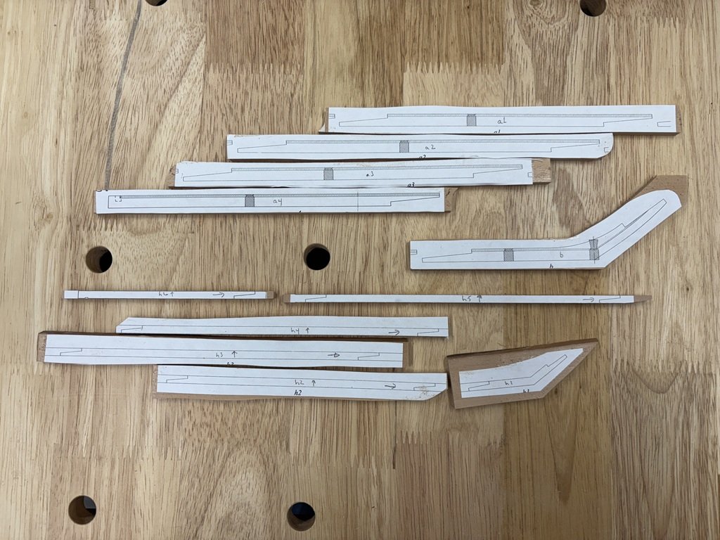
I decided to start work on the cutwater. Templates for all the parts were rubber cemented a sheet of Swiss pear and cut out with the scroll saw - some closer to the lines than others depending on the size / complexity of the parts. This is my first opportunity to fabricate a built-up cutwater and I am looking forward to the experience. Of course the situation leaves me with some questions as how to proceed. Here's the current plan: I've numbered the parts in a perhaps strange order - parts 4 and 5 are numbered in the plans, but the rest are not, so I chose a numbering system that seemed reasonable but would not mirror the intended order of assembly. 1. Fay parts 1 and 2 2. Smooth top and bottom contours of the assembly 3. Fit and add part 6 (remembering to have shaped the top S-curve of 6 beforehand) 4. Form and add parts 3, 4, and 5. 5. Begin matching this assembly (parts 1-6) to the stem. 6. Match the inner side of 7 to the stem 7. Cut the scarf joints on 6 and 7 8. Connect 7 to the 1-6 assembly. 9. Continue shaping the joint between this unit and the stem 10. Add the forefoot to the stem assembly and insure the cutwater matches well with the stem and the joint between part 7 and the forefoot. 11. Set the cutwater in a safe place and have a nice glass of scotch and/or whiskey! Tapering of the cutwater, etc. can then be done at a later date. Please let me know if I am missing something important here. So here are the cutout parts and a start of forming the joint between parts 1 and 2.
-
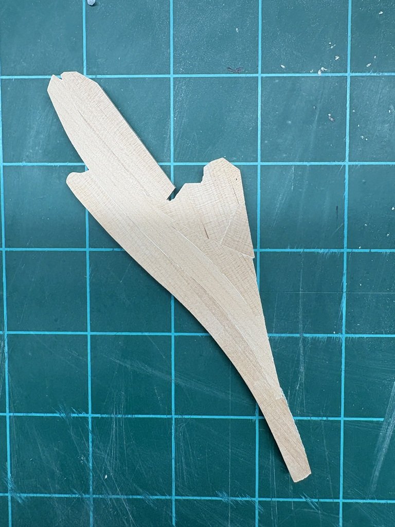
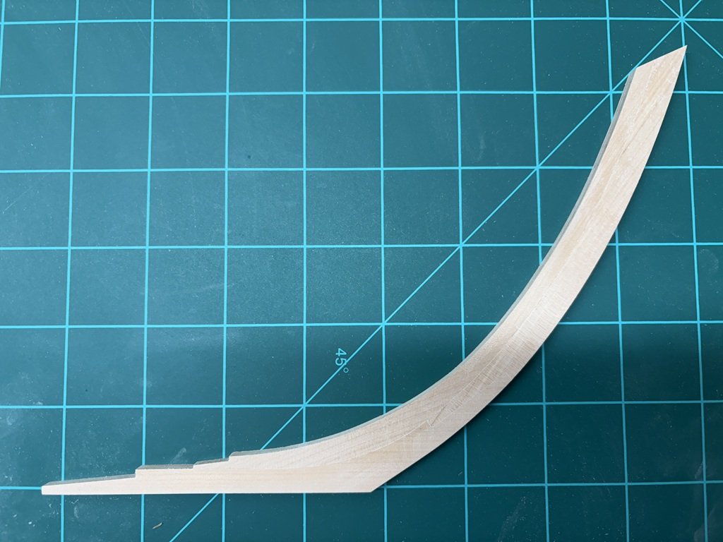
Here's the result of this week's work: I felt that if I worked these joints anymore, the result would start to degrade; hence the decision to attach and move on to another piece. Question: Is it wise to shape the cutwater at this point (and set it aside for a really long time)?
-
And I will be doing the same. Safe travels! Greg
-
All points well taken - expanding / contracting plans and wood, together with the fact lines on a drawing have width. I won't be adding any paper for caulking and yes, glue does take up space. I hope to keep a good eye on the accumulated length / minimize the chance for expansion by keeping track of not just the dimensions of each individual part, but also that of assemblies. So here, the combined width of the apron / stem is as important as the width of the apron and stem individually. Of course finishing individual parts to the exterior the associated plan lines will result in joined pieces to include the thickness of two copies of the lines from the plan plus space taken by glue - so one line width plus glue too much. Finishing individual pieces to where the plan line nearly disappears (on both sides of a joint) keeps the joined combined piece(s) dimensions closer to what the goal is. Either way, assume if one had modeled a keel to be 850mm and ended up 0.5mm in excess of the overall keel length, the length for this assembly l will still be within 0.06% of the desired length [ (0.5 / 850) x 100 = 0.06% ] - for me, I'd call that a win!
-
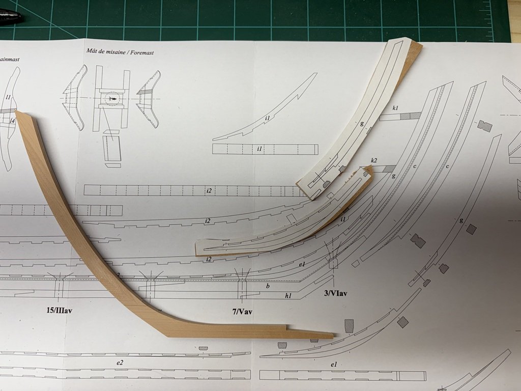
I milled the scarf joining the apron and rising wood segment, then glued the pieces together and set them under glass for more than a day. My plan is to shape the fore side of the subassembly so it matches with the previously made section. Then I will shape the inner side followed by milling the more delicate scarf on the end of the rising wood piece.
-
Just a quick update: It's taken a few days but the fore-foot (b) and stem (c) are connected, shaped and ready to accept the apron (g) as well as the first section of the rising wood (e1). I expect that it will take quite a few more hours of careful shaping to get g and e1 nicely fayed to b and c. The fore-foot (h1) already is shaped to fit correctly to b (and to the next part of the false keel h2).
-
Fortunately we keep our house fairly well controlled in terms of temperature and humidity so I'm hoping that there is minimal dimensional changes going on here! For this project I will make use of the dimensions listed in the monograph as well as the plans. I had read about your use of Mylar in your books and it may be wise for me to think in this direction for future projects. This certainly seems to be a situation where it would be valuable to have CAD files which don't appear to be available for ANCRE publications. But I do have a project in the wings that needs to be done in the next couple of years for a local non-profit. They want I model of a Mackinaw boat and I have agreed to make one for them. Still not sure what draught I will work from, but it appears that I will need to draw the plans myself - it could be a good introduction for me for working with Mylar. I am very much looking forward to seeing the result of your current project; South Carolina (ex L'Indien?) is such a beautiful frigate! Greg
-
Magnificent!
-
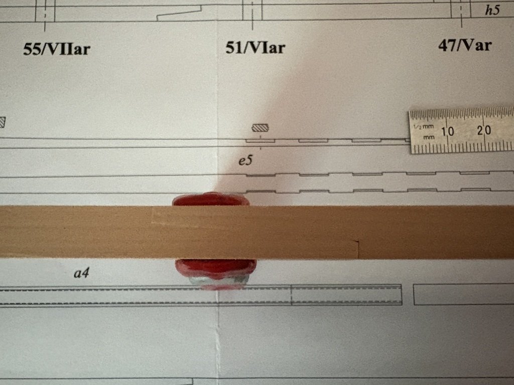
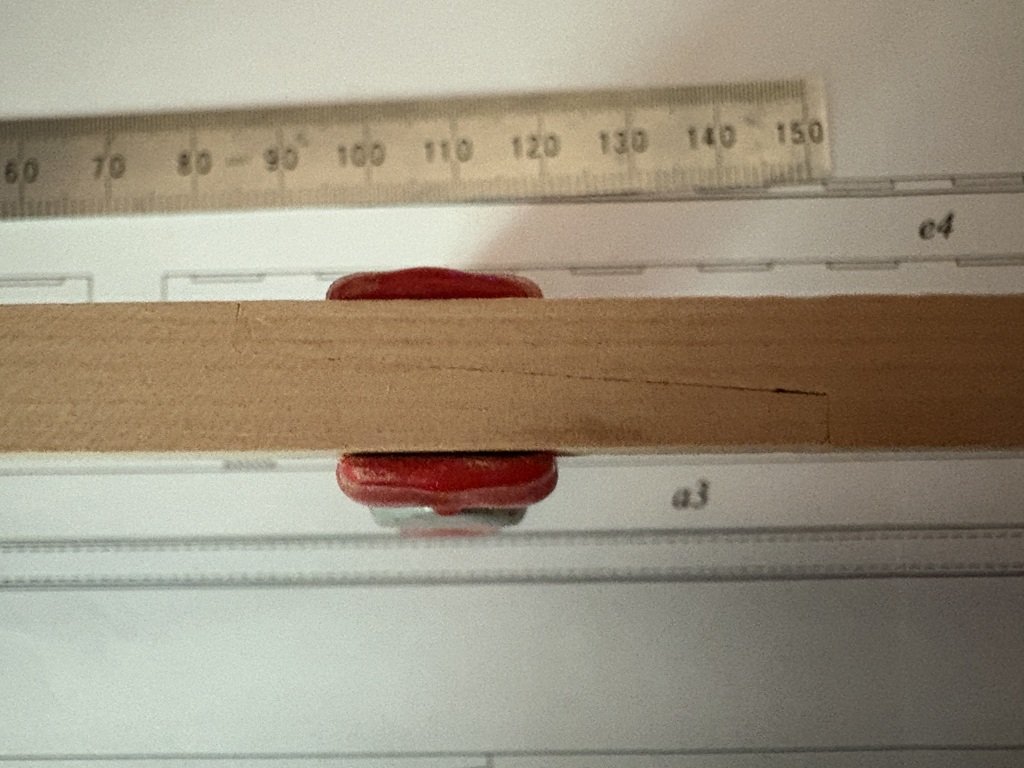
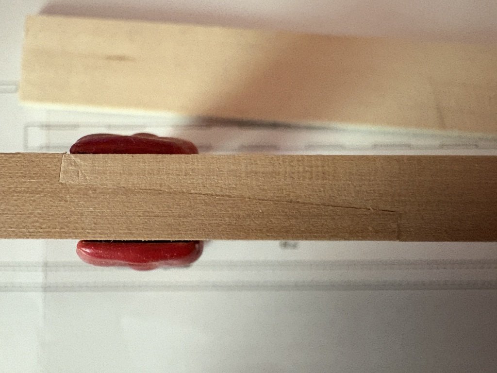
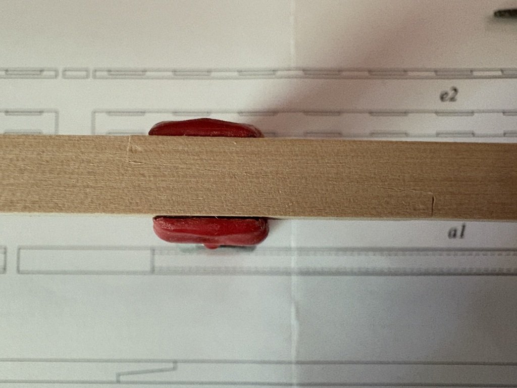
Before refining the joints, the accumulated error in length of the keel was nearly 2mm over the ~80mm unit. After working more on the joints, I've reduced this to less than 0.5 mm; so I'm now within 0.6% of the plans. I concerned that if I go further, I may end up being off by more in the negative side / am I already in the area of contraction / expansion of the paper plans - what to do now? Here's what the 4 scarf joints that link the 5 pieces of the keel from fore to aft: Next up some work on the false keel joints
-
Milled the scarf joints and set the pieces all together: Now they need to come back to my model room and get a little bit of final fitting!
-
Finally all these parts have been milled to their proper dimensions (two pieces I didn't like my first attempt and remade them) - time to start in on the scarf joints! Hopefully milling of the the joints go well so that this step doesn't need anymore redo's.
-
I'm glad you like what you are seeing here. I got a chance to see the work you have been doing as well - very impressive! All the best, Greg
-
After 'tuning-up' the mill a bit, I got a start on fabricating parts for the keel and false keel. I cut out paper templates that were quite wide in comparison to the parts in order to maximize my chances of keeping these long straight pieces nice and straight.
-
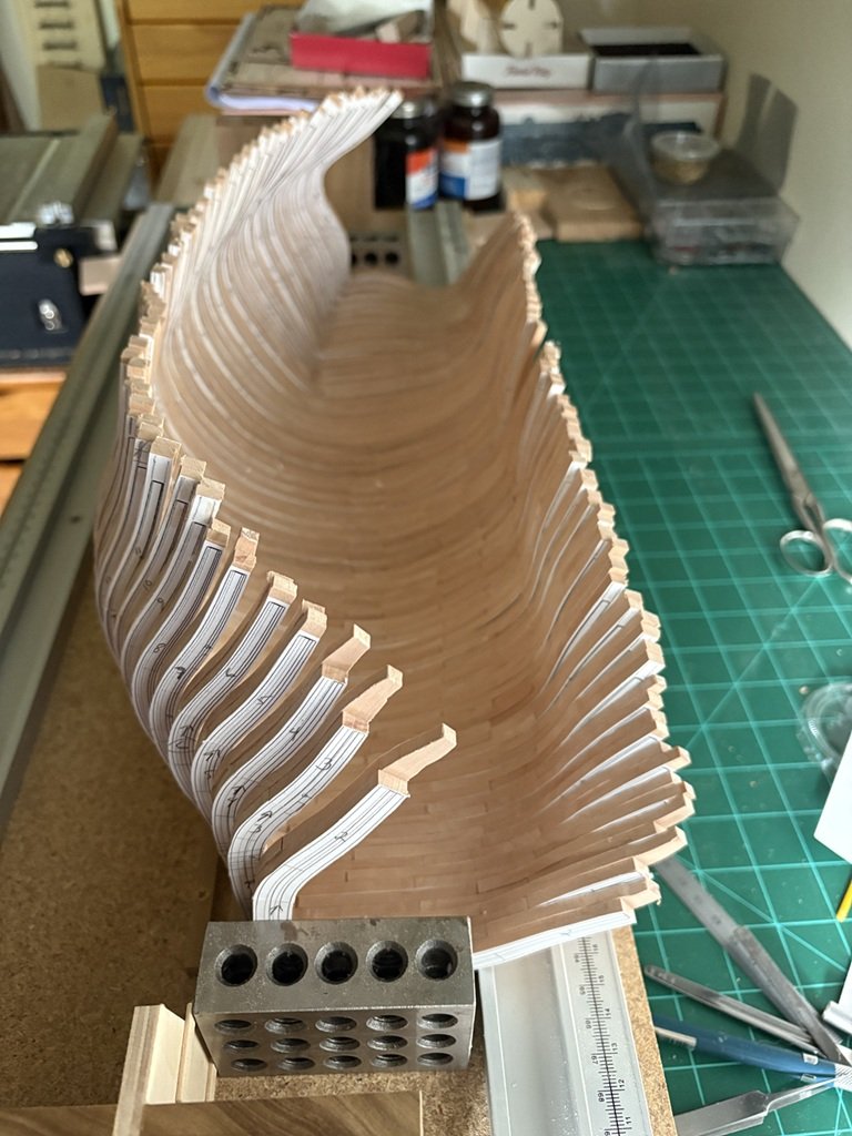
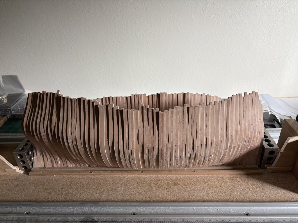
Here are all the full frames together - I think there is an unwritten rule that they need to be stacked up and photographed at this point:
-
Thanks for dropping in, the complement, and for making your very nice build known to me! Greg
-
Here are the last 4 full frames glued up and drying between glass plates. Time to build a keel to set the 55 full frames on!