Greg Davis
-
Posts
807 -
Joined
-
Last visited
Content Type
Profiles
Forums
Gallery
Events
Everything posted by Greg Davis
-
 Keith - Thanks for looking in and I hope that you can continue to do so periodically! I have read your Terror log more times than I'd like to admit - a wonderful build and a superb information resource . Because of you and others, I feel that I will have lighter seas to navigate with this project. I feel that turning this into a solid hull is my best chance for getting a better feel for the hull's shape prior to planking - but we shall see if this is indeed a help or just a lot of sawdust. All the best, Greg
 -
Starting to fill space between bulkheads: Even though this is a double planked model I like the idea of filling space between the bulkheads. I find that I can do a better job fairing the hull if it is 'solid' as opposed to making a judgement from several bulkheads. From my experiences, using filler wood that is similar in hardness and sanding attributes to the bulkheads is advantageous. For example, I once used balsa as a filler and it softer than the bulkheads so when sanded it was easy to make valleys between the bulkheads (which then needed filler, etc.). Here the bulkheads are a fairly soft plywood. While this wasn't planned; a couple of weeks ago I laid plywood underlayment for a new vinyl plank floor in our family room and it turns out that the 5mm plywood I had used is quite similar in hardness to the plywood in this OcCre kit. Hence an in-house supply was readily available for this task. I ripped a bunch of 3/4" wide material and then am cutting it to fit between consecutive bulkheads. Of course the bulkheads are not spaced evenly, so it is best to cut for one space at a time. In each space material is stacked up starting at the subdeck and another stack comes off the false keel. When the two stacks start to overlap one stack is left and the other continues to be built up until the desired space is filled.

-
Today I took the deck back off and sanded the correct bevels onto the top of the bulkheads so that the subdeck would fit nicely. A flexible sanding stick works well for this process. When doing this work, I keep on reminding myself that the process needs to be carried out completely across the top of bulkhead; i.e., not just along the junction of the bulkheads and the false keel in order to preserve the deck camber. The fit of the subdeck was checked and when satisfied, I clamped the subdeck to the false keel / bulkhead structure and then brushed a reasonable amount of glue into all of the joints. This is out of order from the instructions. The instructions suggest planking the deck and then installing the subdeck / deck structure. I chose to attach the subdeck now when it was more flexible and could be used for the bulkhead alignment process. Additionally, if it were the case that any of the bulkhead extensions passed above the subdeck, they could be sanded down prior to the deck installation. While it cannot be seen in this picture, I did mark the centerline of the deck before attaching the subdeck. Additionally, I did consult Betts' text with respect to the upper deck plan to determine the correct width for the center / straight deck planking region. Measuring the plan midship, it appears that the ratio of straight and herring bone patterns is approximately 6:7:6. The width of the subdeck at this point is 4"; so on the model the center deck planking region should be close to 1.5" - this is the width of the section I have marked out. While I'll come back to this later in the build, the deck plan indicates 11 strakes of deck planks in the center section and the model's instructions show 6. As a straightforward modification, I will use 11 strakes of narrower planking here; similarly, I will be using (more) correctly scaled planking in the herring bone regions.


-
Getting right to it tonight. First numbered the bulkheads and other parts that will form the hull's foundation so they get installed in the correct locations: After releasing the bulkheads, I slipped each onto their corresponding slot on the false keel. A few of the bulkheads did not seat down all the way needed, but were close. A couple of swipes with a file made corrections to achieve a good fit. Due to the kit design, the false keel / bulkhead structure cannot be placed in a standard keel holder. I was pleased that the false keel was quite flat / essentially free of any warpage. At this point, the rather vague written instructions state that 'It is important to make sure that the frames are completely perpendicular to the false keel, in order to ensure that the decks fit correctly. To help me get the frames / bulkheads into the correct positions I placed the subdeck sheet over all the bulkheads. Due to kit design, this will line the bulkheads up nicely as the subdeck is notched for each of the bulkheads. I will also not that the bulkhead extensions matched up perfectly with the subdeck notches. Rubber bands were then used to keep everything together before applying any adhesive. At this point, it's pretty easy to see the not quite right hull envelope that has been noted by many builders of this kit. This will probably be as far as I go today as I ponder the next steps.


-
Looking for admission to the HMS Terror Club! Over the years, I have collected numerous kits and monographs of ships. I have two (adult) children and I wanted to build a ship for each that they had picked out. A few years ago my son chose the Lumberyard / Harold Hahn Rattlesnake model and hasn't waivered. More recently, my daughter finally made her pick: HMS Terror from the OcCre kit. I've decided to start the Terror project for my daughter now because she is interested in essentially an out-of-the-box version (that I can fit in my modeling space along with other projects); whereas my son is super detailed oriented (don't know where that came from ) and wants all the bells and whistles on Rattlesnake. Also, this will be very much a start and stop build as I have several other modeling projects going on at the same time - Phantom, BR-18 Locomotive, La Couronne, and of highest priority L' Invention - but this is a mode I like to be in more so than building one at a time. I've read as many of the HMS Terror build logs as I could find on MSW - so much nice work! I have my copy of Betts' HMS Terror book. I have the kit. Time to set the associated expectations and putting some pieces together. Here's what I'm looking to do: Simply build a nice / clean representation of HMS Terror while minimizing the number of upgrades / customizations that can / could / have been done been done by other modelers. This is not to say, some deviations from the kit will not be taken. For example, I do plan on reducing the plank width in order to have deck planking closer to Betts' plan; will likely add the water closets that are aft on the deck; and include masts that are closer to scale. I've been asked to paint the hull, so I won't be going 'all in' on the hull planking, but I will be taking a look at the hull's envelope. Other decisions will be made along the way. I feel really lucky to have the benefit of seeing what others have been able to do with this model - I hope I can do it justice as well! Greg

-
Thanks - I had wondered if you had used a larger toothed slitting blade.
-
One more question! Do you recall what saw blade you chose to do the cutting? thanks, Greg
-
Chris - Excellent subject and work! Would it be possible for you to describe / explain how you were able to part these rising wood pieces off? I have been struggling on how to tackle the corresponding parts on my L'Invention build. Thanks, Greg
-
Chris Thank you very much; I'm glad you stopped in because now I am aware of your beautiful La Renommee build (and log). Greg
-
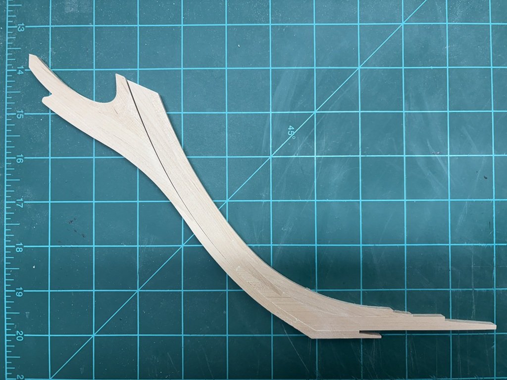
I think that this is the best I can do at this point in time: I'll be putting the head / cutwater assembly in a safe place as I'm not interested in remaking the structure currently!
-
Yesterday I attached the forefoot to the stem structure. Today I spent some time adjusting the cutwater / head assembly to fit nicely to the forefoot / stem structure. I'm finding this to be a challenge; however, it seems like it is getting close. They fit quite well together when a small amount of pressure is used to pull them together. I think I can get a little better fit so there is minimal tension in the joint before setting the setting the head aside for quite a long time. I am glad that I decided to build this assembly now as this fitting process would likely have been even more challenging if I couldn't lay all these parts flat on the bench! So a little more time on the mating process and then I will start adding in the keel.
-
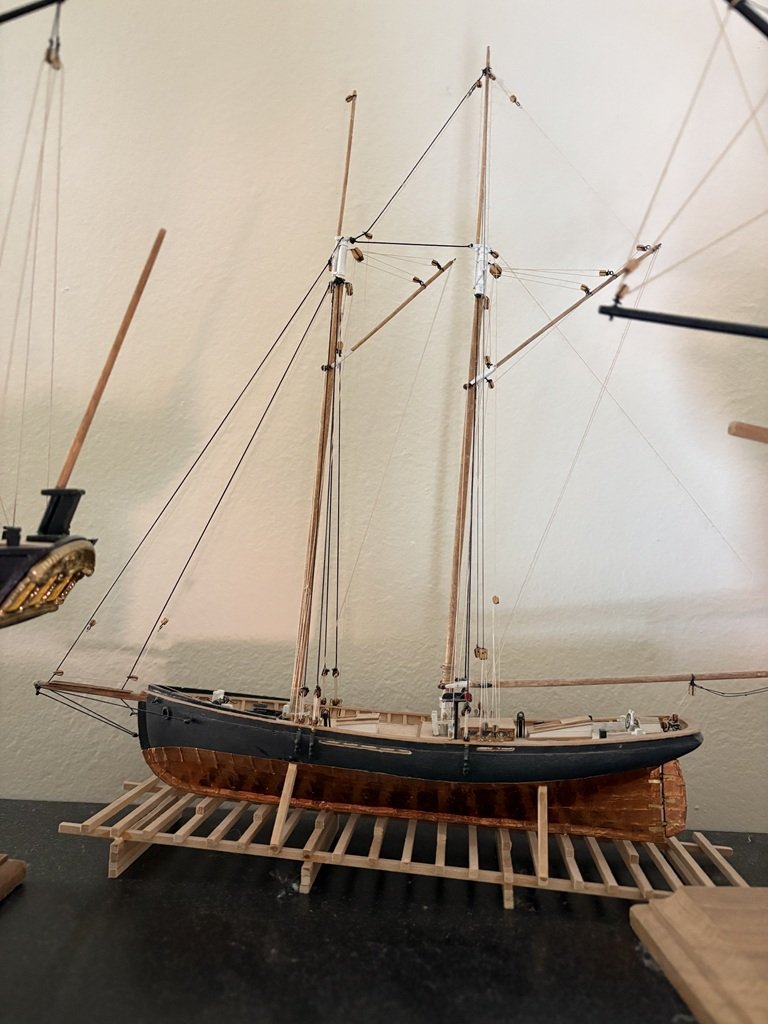
I've finally made of my mind on the way this model will be displayed - I kept going back and forth between launching ways and a minimal cradle. Launching ways won, so there will be the opportunity to compare ship and mounting method with the old 1:96 Phantom. I cut the launching ways I had made down in size by quite a bit and stained it Golden Oak. Several support beams will be fashioned to keep the 1:48 Phantom sitting nice and level on the slipway. Maybe time to bring the deck back out in the open?
-
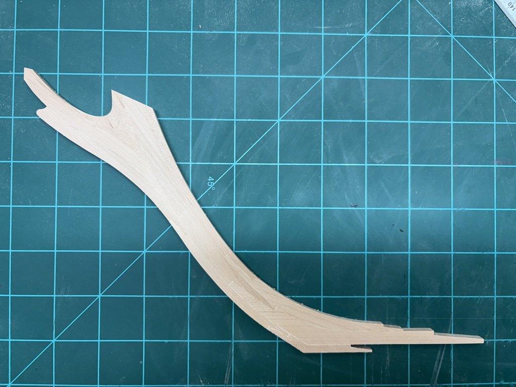
The cutwater / knee of the head assembly is nearly complete. Lots of slow going to get all the graceful curves sanded. I am now making adjustments so that this work fits neatly with the stem / forefoot assembly. I also need to drill / mill a hole and slot for future rigging purposes.
-
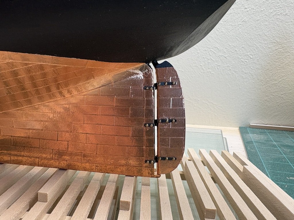
Today I hung the rudder using the phot-etched parts provided. The result is quite acceptable (to me): I chemically blackened the photo-etch parts with Brass Black by Birchwood. Before attaching they were buffed as clean as possible with a Dremel attachment. I'm debating whether or not I should blacken / paint the heads of the brass nails that I used here. Since there was no explicit instructions provided for installing the rudder hardware I thought I would outline the way I did the work: There are specific orientations for the gudgeon and pintle pieces. You can pick up on the orientation of the larger gudgeon piece if you look carefully at the one rudder installation picture in the manual. However, the picture below may make it easier to see what needs to be done; i.e., the holes in the back plate need to be above the associated gudgeons so the pintles mount higher up as needed. The gudgeons should be bent to the side of the scores in the photo-etch part so the exterior of the bend is smooth. Pilot holes should be drilled to accept cutoff pin heads used to simulate bolts; similar for the three locations used to pin the rudder to the stern post. I inserted pins in the three attachment locations, cut them off leaving ~ 1/16" and pressed the rudder up to the pins to mark locations to place the pintles on the rudder. The pins were then removed. Holes were drilled into the rudder at these three locations and the mounting / alignment pins were CA'ed into the holes in the rudder. Pintles were then threaded over the alignment pins and attached to the rudder. Again the PE scores go to the inside of the pieces when attached. Care needs to be taken that the pintles are attached with the correct orientation on the rudder - there is an up and a down; if not respected the pintles will not fall just above their associated gudgeons. Pin heads were then used to finish the pintle installation. Finally, the rudder was glued to the hull making use of the three alignment pins that went exactly were they should!
-
Thank you for the support! I was looking at your list of future builds and I see we share Slo-Mo-Shun. I have the kit sitting on a shelf. A couple of years ago when I was visiting my son in Seattle, I had him take me to the Hydroplane & Raceboat Museum in Kent because I got the impression from their website that Slo-Mo-Shun IV was in their possession. Drove out there, had a great time, saw a lot of really cool stuff - and found out that Slo-Mo-Shun IV was hanging in Seattle's Museum of History and Industry which is located less than a mile from where he lives!

-
Thank you very much!
-
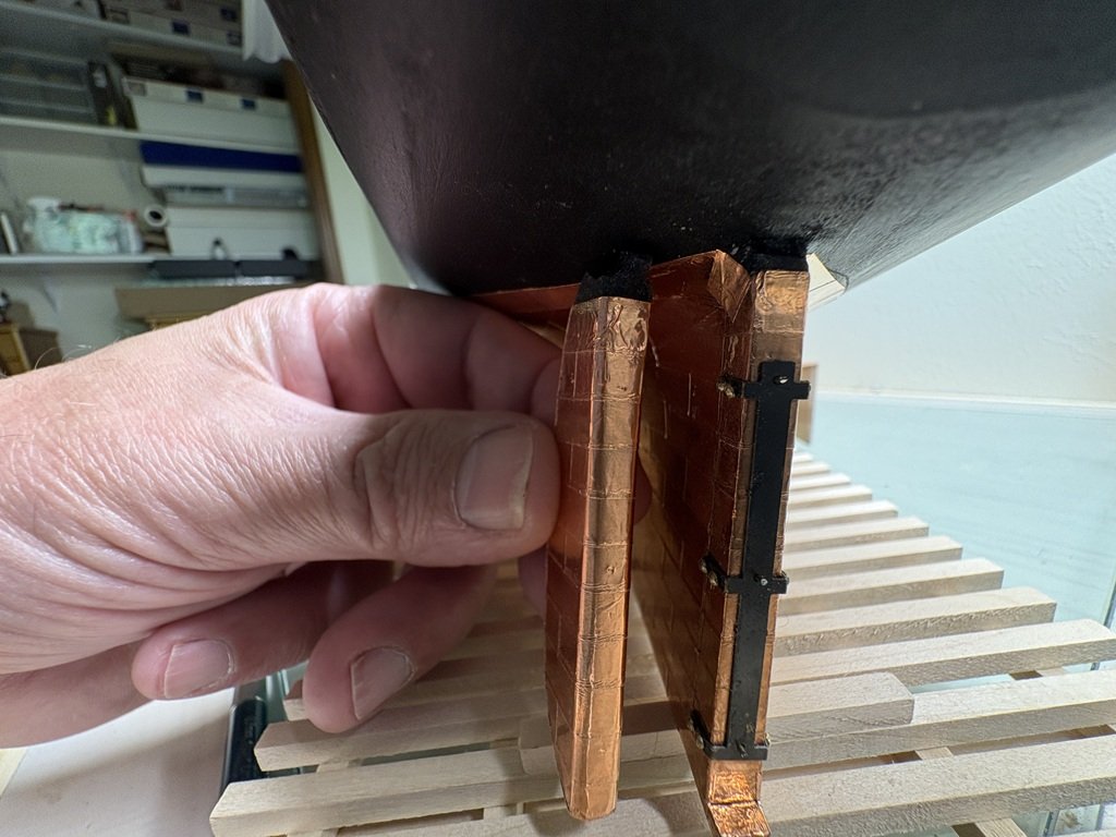
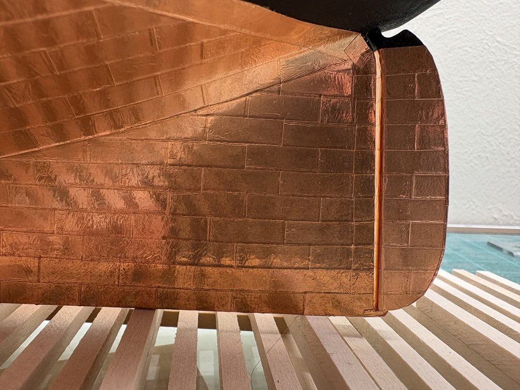
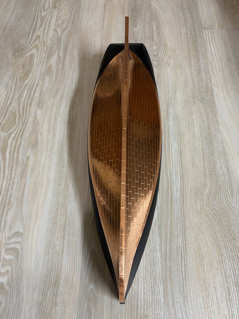
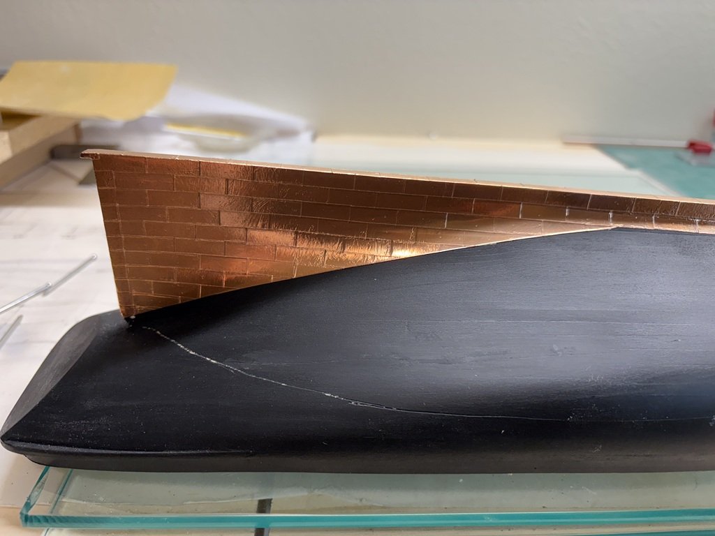
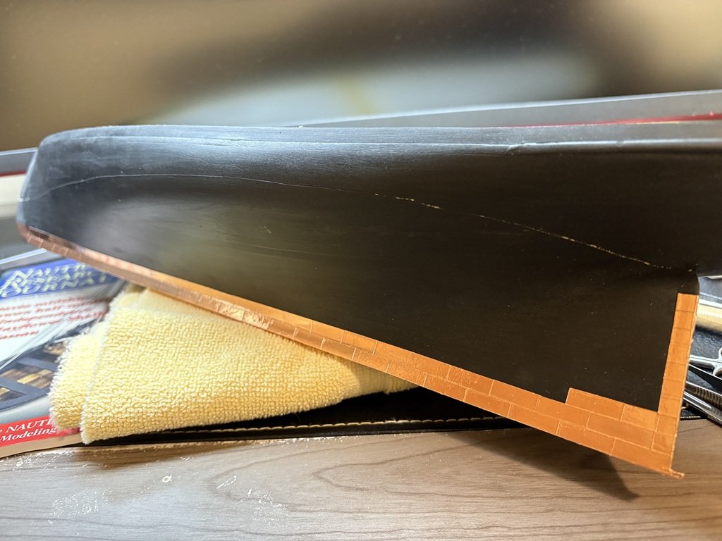
I've managed to copper plate the rudder. Fortunately the belts line up well between hull and rudder. Time to blacken some brass and get the rudder hung.
-
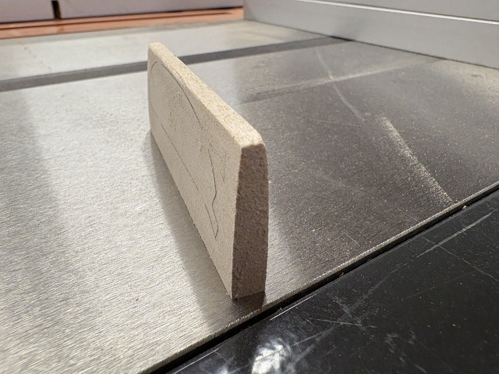
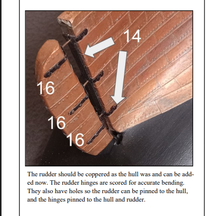
Started the rudder work today. Before freeing the rudder from the wood sheet that it was laser cut into, I tapered the rudder fore to aft by nearly 1/16" each side. Actually I milled the taper by securing the rudder blank to my mill with a 1/16" plate lifting the fore side of the blank - this way I tapered off ~ 1/16 by the aft edge of the rudder. The blank was flipper over and a 1/8" plate was used to lift the blank - this way I could mill a taper that reduced the aft edge on this side also by 1/16". Next the rudder was freed from the blank and additional shaping / fitting was done. The fore edge is now rounded off a bit (may round it a little more), and the rudder post is a cylinder as it meets the hull. Minor height adjustments needed to be made for the rudder to fit close to the stern post. Soon the top will be painted black and the rest coppered. Just a comment about the instructions associated with the rudder installation. I hope I haven't missed something (I search for rudder in the PDF of the instructions for rudder several times); but there only seems to be one picture / paragraph dedicated to this part of the build: From the picture, I can see that the fore edge of the rudder has been rounded, and it also looks like the rudder has been tapered. My concern is that, I can't find any text in the instructions (nor an illustration in the plans) that speaks to shaping of the rudder. There should be some instruction / notes in the instructions given that this is a 'beginners kit'. Going back to the picture, the rudder attachment method is clever and should make for a nice mount. I'm definitely going to try out the included photo-etched parts here. The gudgeons are combined and spaced on a single piece of brass; however the three pintles are separate pieces. There are three holes in the gudgeon piece that need to align with holes in the pintles in order for the described pinning to work. It would have been nice, if the instructions had included a few words on how to get the photo-etched parts lined up so the pinning went as expected.
-
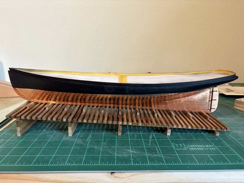
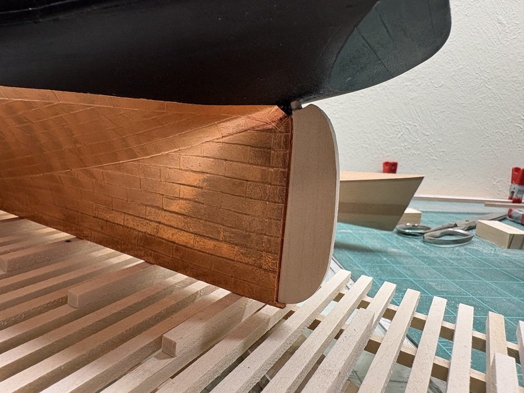
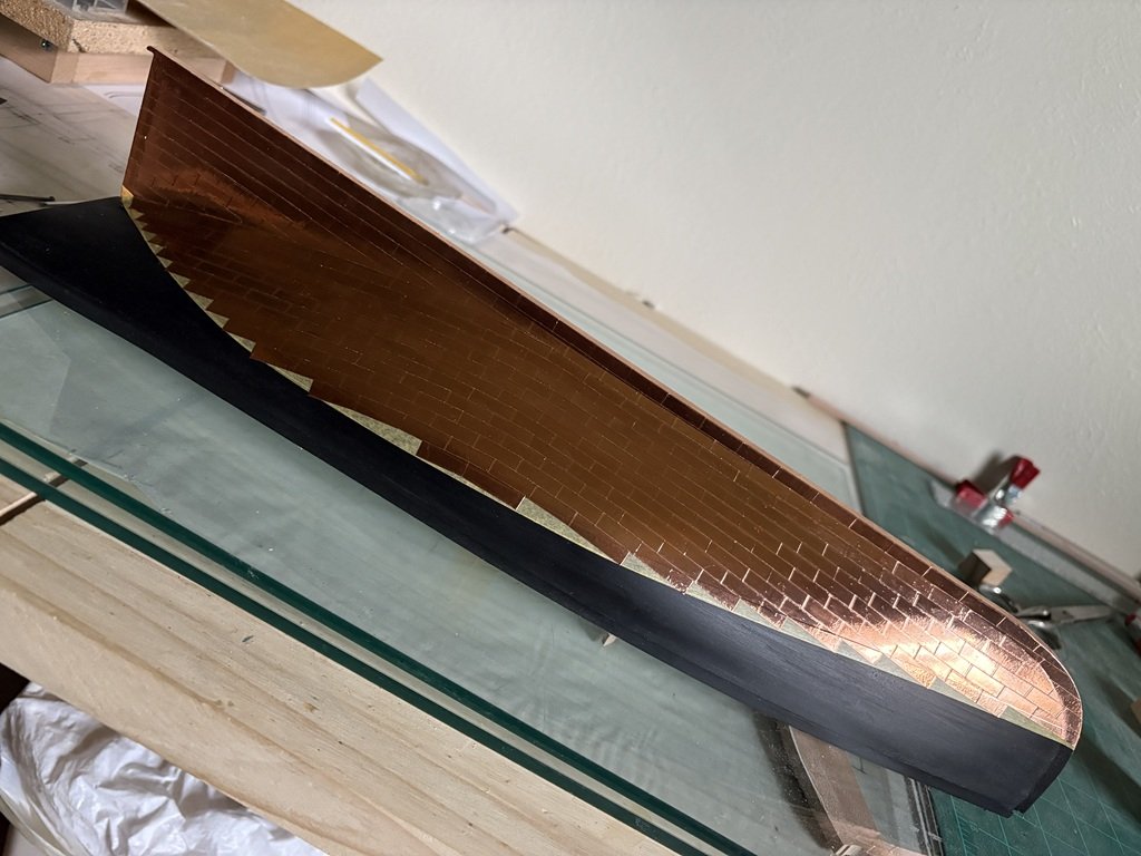
Finished coppering the hull and now have extra respect for those modelers that copper huge warships! Still need to contour the rudder before doing a little more plating.
-
Do it! Here's my 1:96 Phantom (2007) - safe, but not cased, on a shelf for now: The copper was not treated in any way; it is a bit darker now but still surprisingly shiny. Waterline is a little more wavy then my current iteration! I see that I used the copper tape right off the spool so the plates are 1/4" high and I did not have a separate belt for the aft portion of the hull - apparently I did not follow the Chuck Passaro Phantom Practicum very well. I still remember struggling with adding hooks to the very small blocks amongst other challenges. That kit was really was on the small side for a first build and I am glad that the larger 1:48 scale model is now available.
-
Finished plating the port side of Phantom today. I had placed a strip of tape to mark the water line / position of the last line of plates:
-
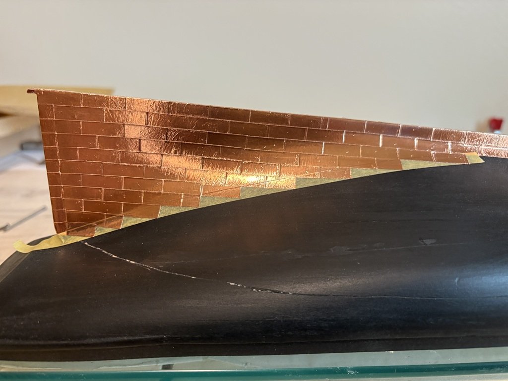
I marked off the first belt with Tamiya tape and plated the first belt so that it overlapped the tape. After making sure the copper foil was burnished quite well to the hull in a way that I could easily see the tape edge, I used a new scalpel blade to cut through the foil and pealed off the tape. Ready now to start the second belt.
-
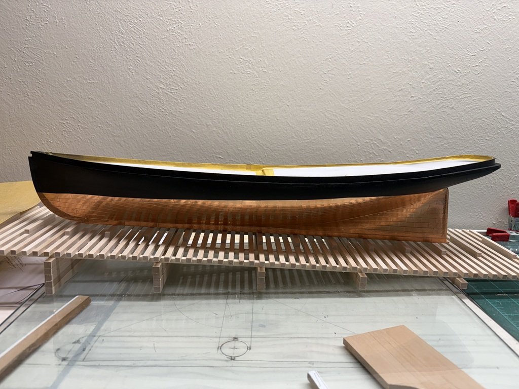
I've started to copper the hull. This is only the second hull I've tried to cover in copper foil - my 1/96 scale Phantom was the first, back in 2007. I hope it doesn't look too bad when done! So here's what I've done on day 1: Keeping the detail level - no treenails in the hull planks (nor deck), so no fasteners in the copper plates.
-
Greg - I have a light box as well, but never thought of using it for that purpose - duh! Thanks for the great idea and supportive comments, Greg
-
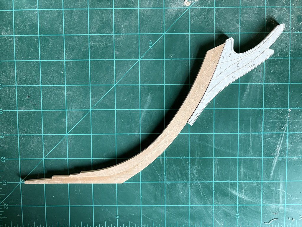
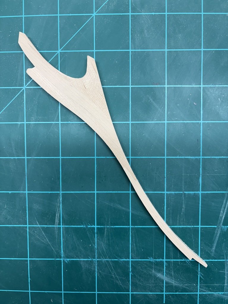
Cleaned up / milled out some wood above gamming knee and lengthening timber (4 & 5). I didn't want to accidently catch something on one of the rough edges and / or slots that were along the top. Once that was done, using a spindle sander, I did a preliminary sanding of the back edge that will match with the stem. This actually resulted in a better than expected start to the final shaping: