Greg Davis
-
Posts
807 -
Joined
-
Last visited
Content Type
Profiles
Forums
Gallery
Events
Everything posted by Greg Davis
-
 Today's little project - a saddle to sit on: It was shaped out of C Boxwood and is approximately 1 x 1.5 cm. Right now the saddle is shiny because it was just coated with linseed oil.
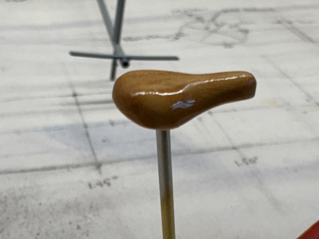
- 288 replies
-
- 12
-

-

-
- Santos Dumont No. 18
- hydroplane
- (and 1 more)
-
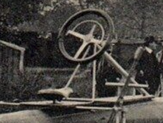
A couple days of work on the steering wheel has gotten me to here: First I cut and milled a piece of brass to serve as the spokes of the wheel together with a rim. Two pieces of C Boxwood with a circle cut out were used to sandwich the brass piece - all attached with epoxy. Then the exterior was sanded to about the correct diameter. Sanding the wheel to a round cross-section then followed. A few more details to add, but this is what I'm trying to mimic: I feel that I am getting close - probably as close as my skills will allow!

- 288 replies
-
- 15
-
-
- Santos Dumont No. 18
- hydroplane
- (and 1 more)
-
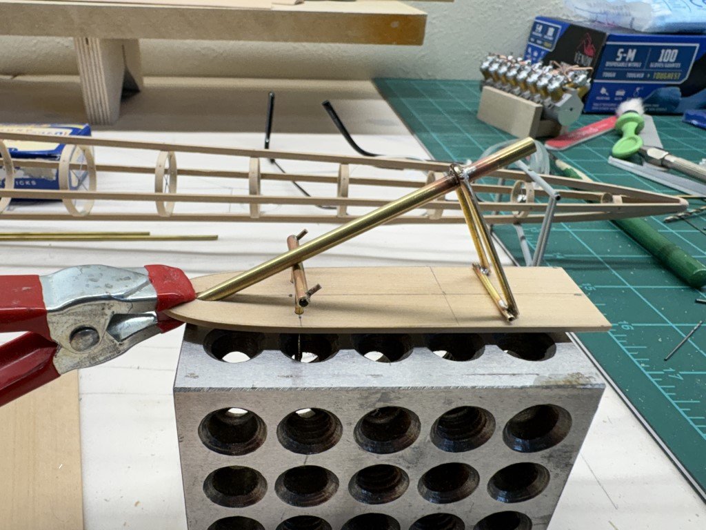
Here's my start on the cockpit. I've made the platform, the steering column structure and the footrest. I'll trim down the parts that go thru the cockpit after they have been attached. Still to come the saddle / seat and the steering wheel (doesn't look easy at all, ugh!).
- 288 replies
-
- 10
-
-
- Santos Dumont No. 18
- hydroplane
- (and 1 more)
-
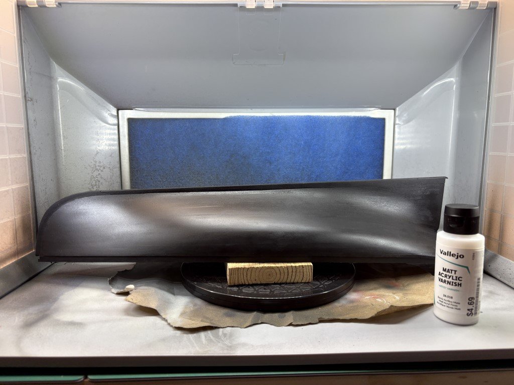
I have not lost interest in this model, but I have a few other projects going on and like to go back and forth at times! One of the projects, the Santos-Dumont No 18 Hydroplane has elevated to the top as I would like to take it to a modeling contest in mid-May. I will be spending most of my time on that; however, every model has its downtime for one reason or another and that will be the time that Phantom and my OcCre BR 18 Locomotive projects get for the time being. After that who knows - there must be 30+ models in the que! Finally 'fixed' the paint issue, and today I applied the first coat of varnish to the hull. It will get another tomorrow and then it will be set for marking the waterline and some copper.
-
Yes, they don't seem to have a large chord. I've done my best to interpret a number of photographs and then made them with a 2cm chord - that would make them roughly a foot in reality.
- 288 replies
-
- 4
-
-
- Santos Dumont No. 18
- hydroplane
- (and 1 more)
-
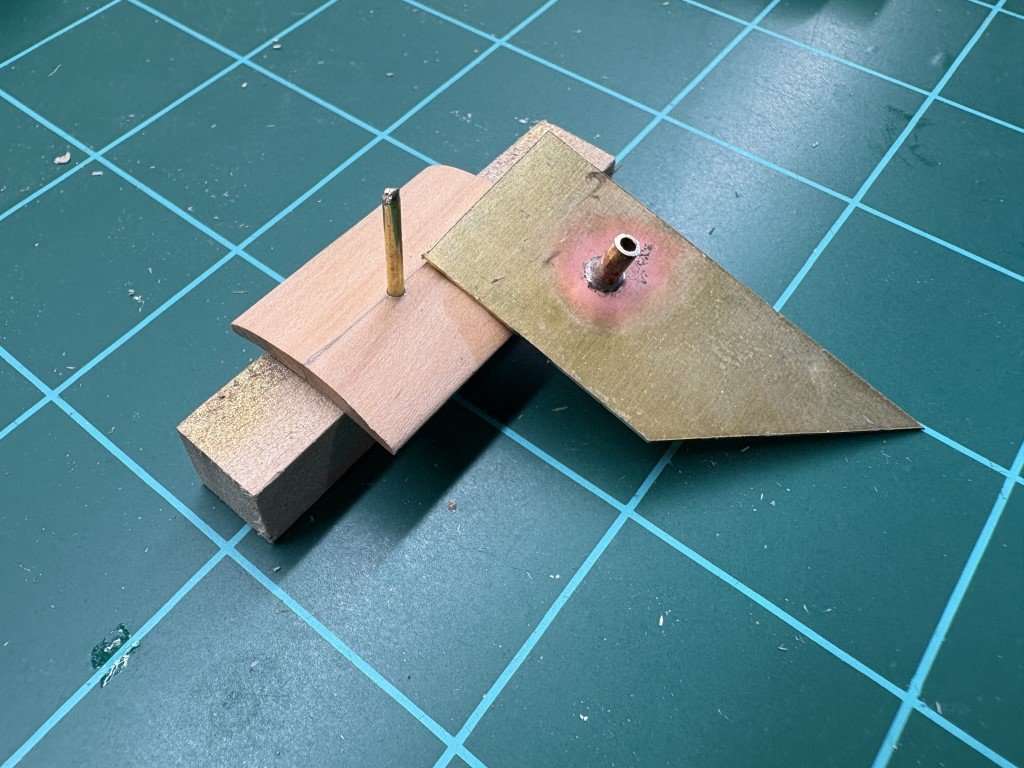
I made a small jig to bend the hydrofoil shape into the brass. I added a brass rod to the jig so that the tubes in the attachments would be in the same fore-aft location after being bent. The four attachments are getting close to their final shapes now - just a bit more adjustment mostly to correct 'spring back' from the initial bending. Here I'm taking a look at how they fit to the hydrofoils when mounted on the boat. I've added all the subcomponents I have finished for this picture as I was curious on how the whole piece of work was coming together.
- 288 replies
-
- 12
-
-
-
- Santos Dumont No. 18
- hydroplane
- (and 1 more)
-
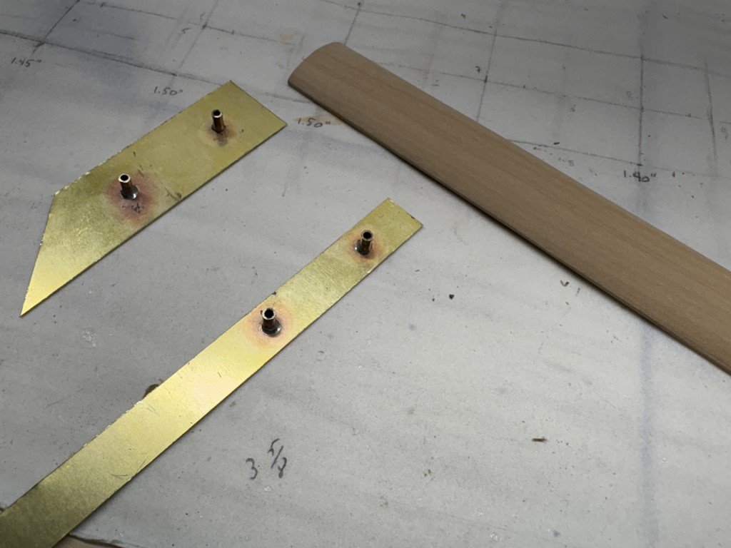
Just a bit more progress for today - this is the start of the attachments that will hold the hydrofoils to the pontoon harness and the rear metal work. The brass sheet was drilled to the diameter of the brass tubes and then the pieces were soldered together. The brass sheet will be bent/fitted to the hydrofoil shape on this spare piece of shaped wood. Then I can trim them up for a good fit to the actual hydrofoil pieces. The thin ones are going in the back and the wider ones in the front. I'll paint these to match the other metal structures.
- 288 replies
-
- 7
-
-
- Santos Dumont No. 18
- hydroplane
- (and 1 more)
-
Craig - No I am not covering the model - it will be done as a framed model. With that said, I have considered using the turned pontoon and nacelles (that I made to 'test' my plans) to make a second model at some point. That model would be completely painted and would show no internal components. However, this is pretty low on my to do list! Greg
- 288 replies
-
- 5
-
-
- Santos Dumont No. 18
- hydroplane
- (and 1 more)
-
True - and we're not trying to redesign this iconic hydroplane!
- 288 replies
-
- 4
-
-
- Santos Dumont No. 18
- hydroplane
- (and 1 more)
-
In correspondence with Professor Catalano, a professor of aerodynamics at the University of Sao Paulo and Santos Dumont researcher, he wrote: 'He was unsuccessful after the powered model lateral instability in water.' After reading this, I thought of the problems WWI fighter pilots had with torque from their plane's engines. From a physics perspective, mounting the engine on a pylon would only serve to make that type of problem worse. I then wondered why he didn't try to correct this using an asymmetric design. I didn't think of moving the engine, but rather moving one of the outriggers / nacelles further away from the main pontoon. I'm also guessing that the reason we have discussed the cockpit location was partially due to the instability problem - leveraging his weight further to the rear would have helped with the bow getting pushed down. I have no idea why he ultimately gave up on the project - perhaps it just wasn't as interesting as flight to him!
- 288 replies
-
- 3
-
-
- Santos Dumont No. 18
- hydroplane
- (and 1 more)
-
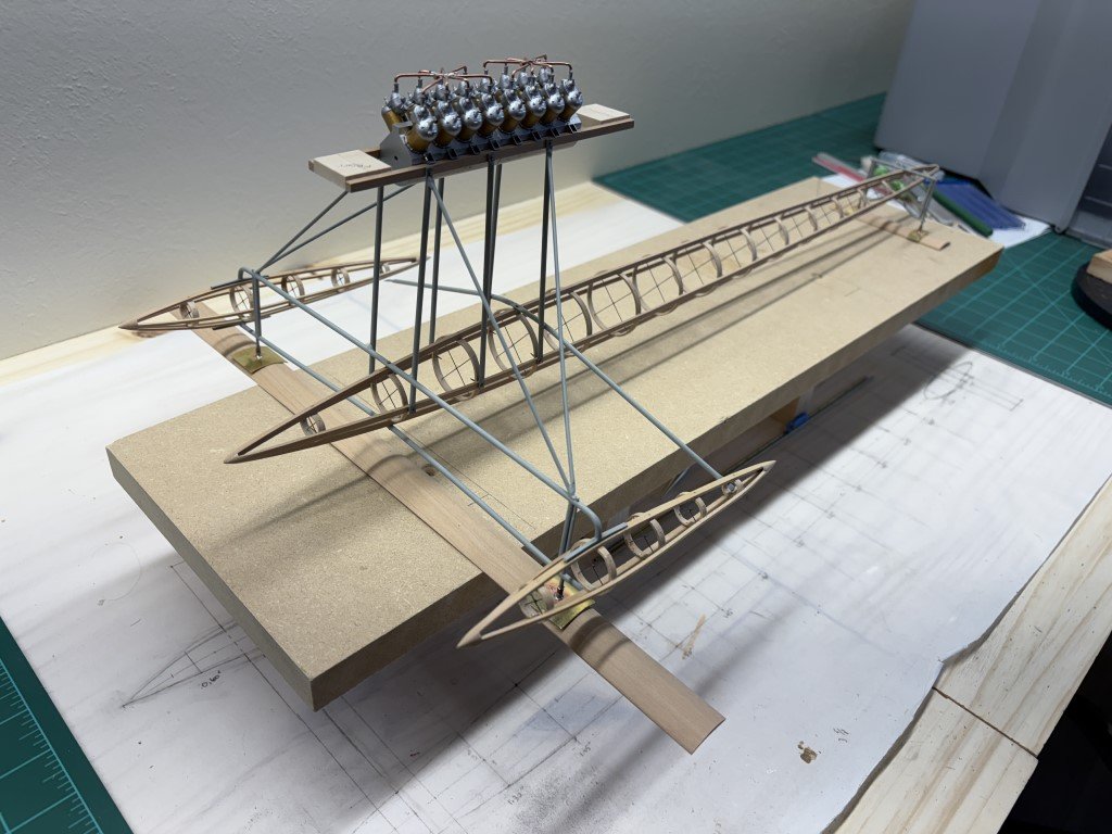
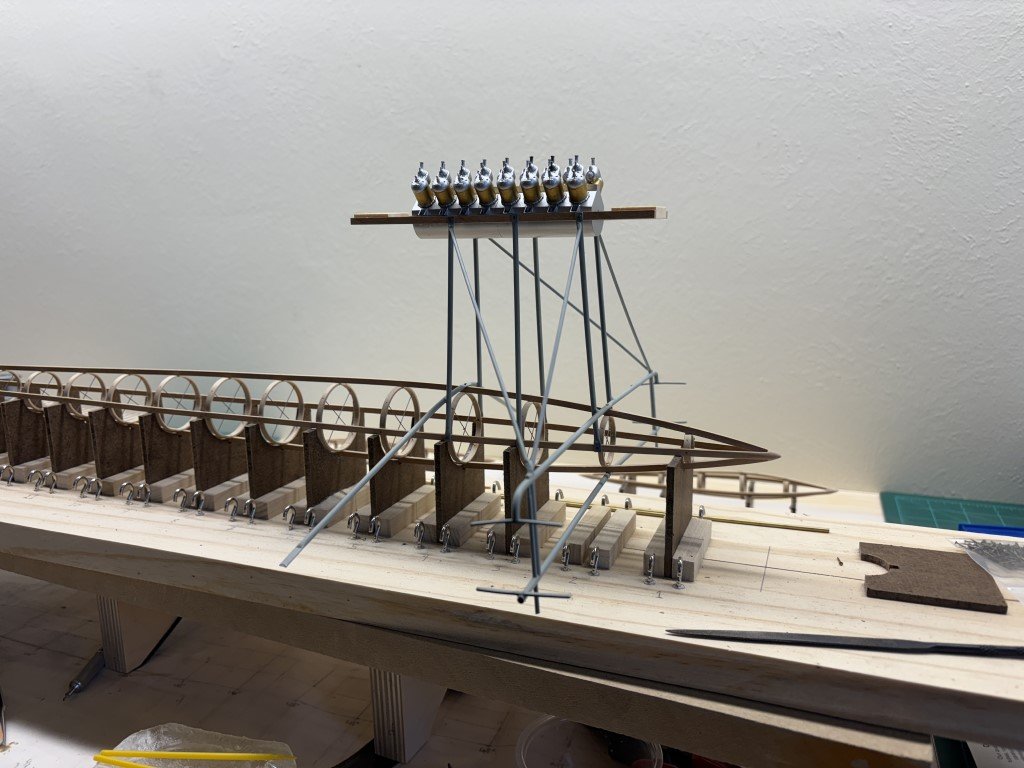
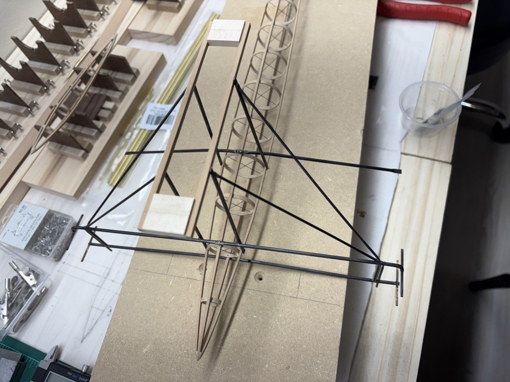
Got a bit excited and needed to post a picture! The harness is now permanently attached to the pontoon. The wooden engine mounting strips were drilled to match the mounts on the engine block. The strips currently are spaced by blocks and are overly long - they will be reduced to the correct size when it is time to secure the engine in place. Here I have test fitted / set the engine in place and was quite satisfied to see that the harness is plenty strong and everything seems to line up as needed. I'll be able to continue some of the work with the model set on the original building jig. I had not glued the supports so that they could be removed for special purposes. Here the second support is removed and there is actually space to mount the hydrofoil below without interference from the jig. The second support from the rear has also been removed so that there is space for the rear hydrofoil mounting structure. Onward we go - it is nice to see the subassemblies fitting!
- 288 replies
-
- 10
-
-
- Santos Dumont No. 18
- hydroplane
- (and 1 more)
-
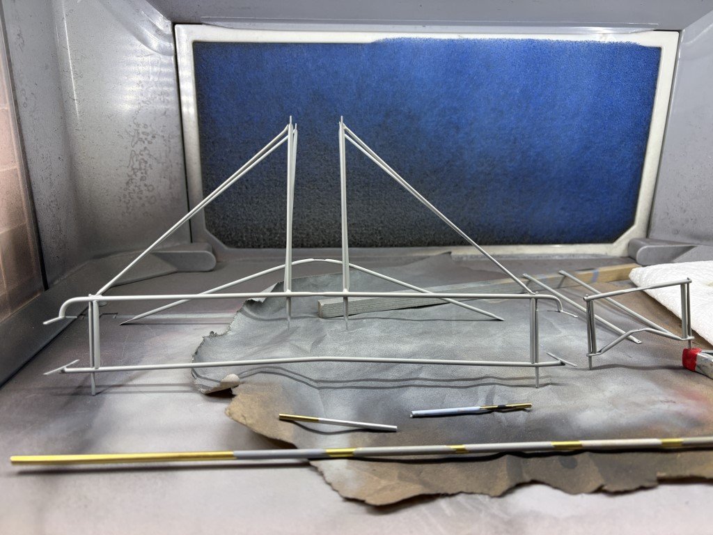
Thank you Craig for all the help you are providing! I looked more at pictures of the boat and decided that the pontoon harness should be lighter in color than the blue/grey pontoon and nacelles. So I've gone more toward the grey tone with a touch of blue. I looked though all the blue and grey offerings in the Vallejo Model Air lineup and went to the local Hobby Town and picked up a variety of possible colors. Did some tests on brass tubes to see what they looked like as well as how they matched up with the other materials used in the model. Finally decided on using Vallejo Model Air Grey Blue: Here's what it looks like now: I think this looks much better than when it was blackened.
- 288 replies
-
- 12
-
-
- Santos Dumont No. 18
- hydroplane
- (and 1 more)
-
Craig - Amazingly clear images - how do you do that???? There are some references to the hydroplane in terms of coloration - light blue / bluish-grey had been reported. I'm waffling on the color I'm going to use. Greg
- 288 replies
-
- 4
-
-
- Santos Dumont No. 18
- hydroplane
- (and 1 more)
-
BR-18 Locomotive by Greg Davis - OcCre - 1/32
Greg Davis replied to Greg Davis's topic in Non-ship/categorised builds
Here is the wood framing for the cab. The six pieces slot together nicely. Note how the bottom of piece 40 goes across the cab floor. Once the glue is dry, that strip will be removed - while not noted in the instructions I was careful to not apply glue down there! Later the exterior of this structure will be covered with bass sheeting.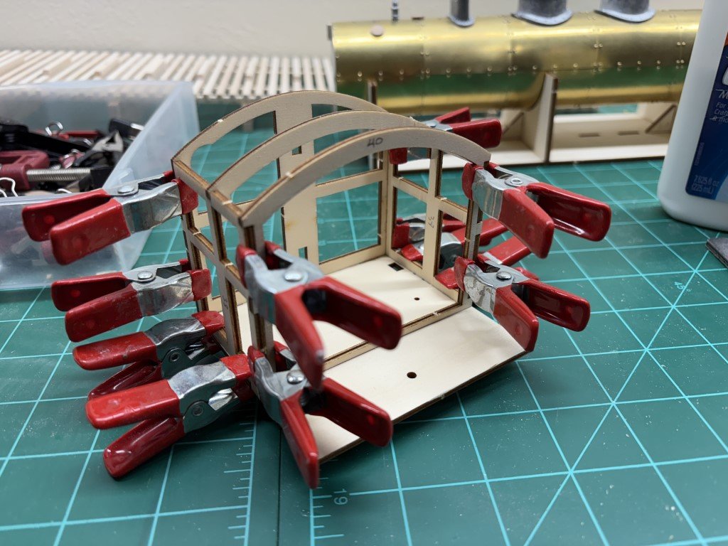
- 33 replies
-
- 11
-
-
Yes, that is a good idea. If all goes well, I would like to have the model finished by mid-May so that I can bring it to a model boat and ship contest that is held about a hours drive from my home. It would be unfortunate to have it damaged in transit and/or by touchy fingers!
- 288 replies
-
- 4
-
-
- Santos Dumont No. 18
- hydroplane
- (and 1 more)
-
That does seem reasonable, now that you mention it! Months ago, I had looked into the history of aluminum tubing and it didn't seem to fit quite right for the time period. So I did then think more about steel tubing as it was being used in the bicycle manufacturing process and it is said that SD had made use of bicycle wheels from Peugeot on the 14bis. Related, the steering wheel on the hydroplane may be Peugeot as well. Anyway, I hadn't thought about galvanized steel - the zinc coating would give the lighter color and importantly the rust proofing for his creations!
- 288 replies
-
- 4
-
-
- Santos Dumont No. 18
- hydroplane
- (and 1 more)
-
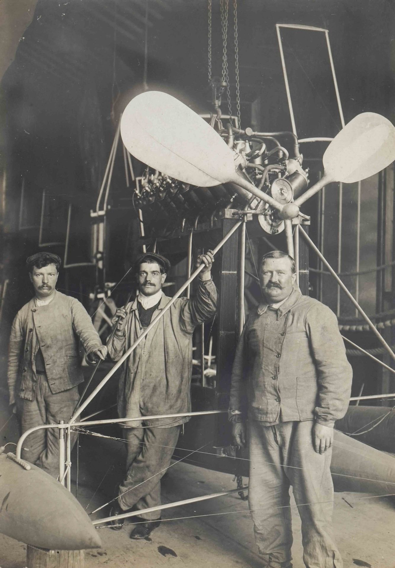
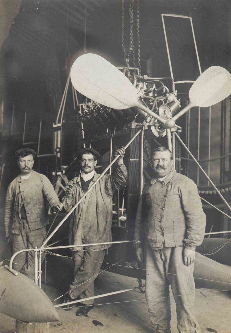
Yes, I will be 'rigging' the model. It seems that SD really liked the big aluminum propeller blades. From the pictures of his machines that I've seen, the only craft that used a more modern two-bladed wooden propeller was the Demoiselle - his final airplane.
- 288 replies
-
- 3
-
-
- Santos Dumont No. 18
- hydroplane
- (and 1 more)
-
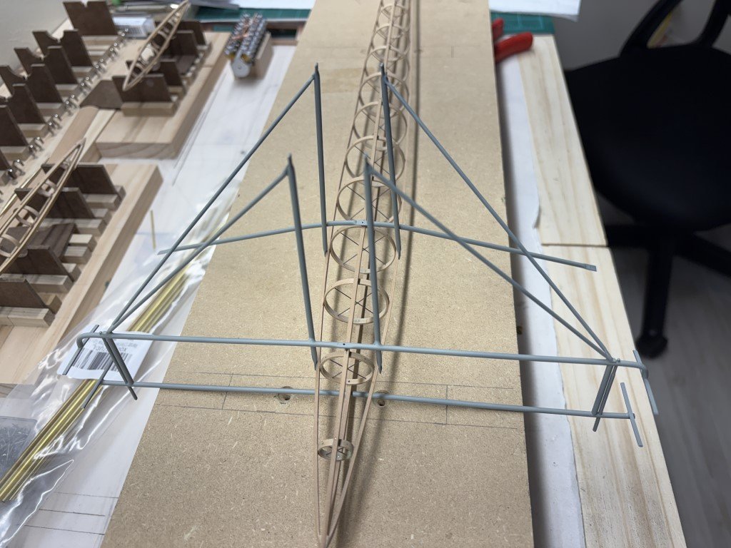
A while back I chemically blackened the pontoon harness. I've looked at it for days - disliking it more and more. Today I stripped the structure back to clean brass. I'm now going to prime and then paint it aluminum. Hopefully that will get this back to a lighter color seen in photographs of the craft: I've spent a lot of time wondering as to what metal was used in the boats construction - steel, aluminum, other. It is known that the propeller is aluminum and the color of the pontoon harness / engine pylon seem to be similar. Blackening was not good; hopefully painting is better!
- 288 replies
-
- 7
-
-
- Santos Dumont No. 18
- hydroplane
- (and 1 more)
-
BR-18 Locomotive by Greg Davis - OcCre - 1/32
Greg Davis replied to Greg Davis's topic in Non-ship/categorised builds
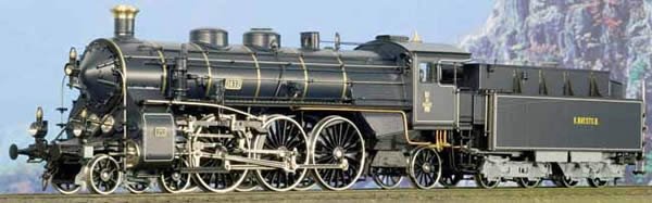
I have finished the first phase of the build. All the main boiler castings have been added. The instructions tell me that it is time to prime and paint the boiler! I'm now having reservations about the light blue / red color scheme I had picked at the start - I'm concerned that it may look too 'toy-like' for lack of a better description. Still don't want to have it in green. My feelings are now tilting toward this blue / black scheme: This is one of several color schemes that Micro Metakit has produced the BR18 in. By the way, this HO brass model sells for about $2,300. Yet, some people tell me that making wooden ship (and other models) is a costly hobby!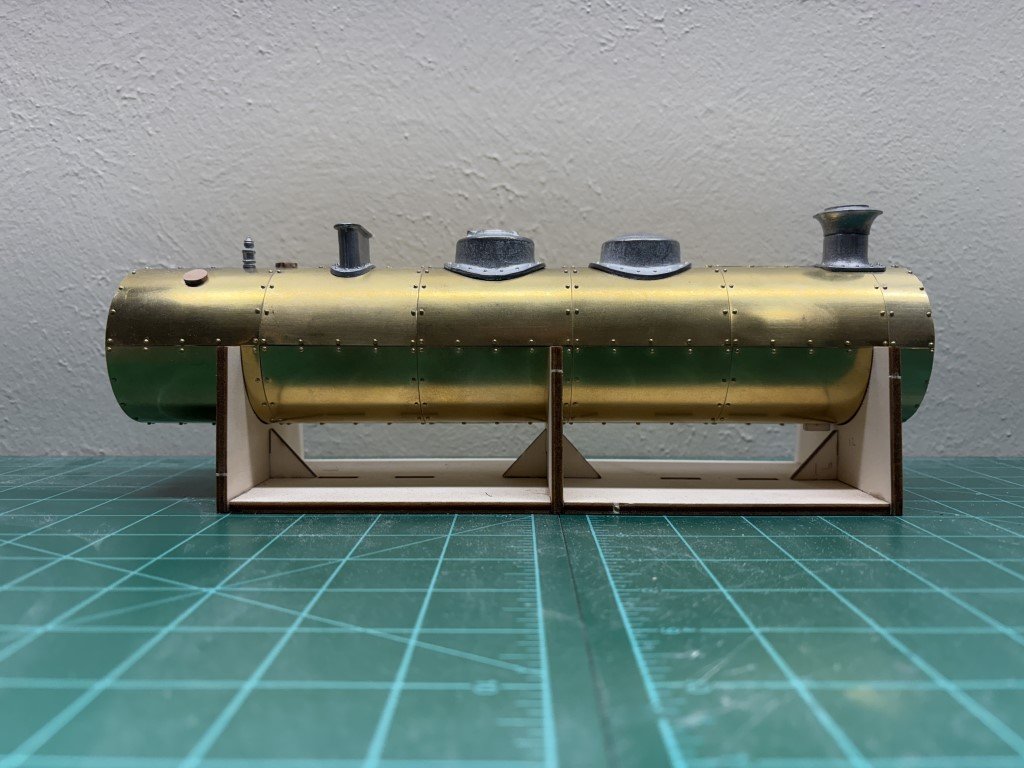
- 33 replies
-
- 10
-
-
BR-18 Locomotive by Greg Davis - OcCre - 1/32
Greg Davis replied to Greg Davis's topic in Non-ship/categorised builds
Everyone - Thank you so much for all the input - I learn so much from all of you! Greg -
BR-18 Locomotive by Greg Davis - OcCre - 1/32
Greg Davis replied to Greg Davis's topic in Non-ship/categorised builds
Interesting! -
BR-18 Locomotive by Greg Davis - OcCre - 1/32
Greg Davis replied to Greg Davis's topic in Non-ship/categorised builds
I agree with wefalck wrt the rivet situation - in pictures of actual BR18's that I have seen, such a rivet pattern is missing. The pictures project do show metal bands at the locations that OcCre places the yellow stripes. It seems likely that the boiler sections were welded with joints reinforced with the bands. The rivet less portrayal is also noticeable in models produced for model railroading. So I think it is safe to conclude that the noticeable rivets need for assembly of the OcCre model are contrary to the actual construction of these locomotives. The final product of this modeling adventure certainly will be a 'representation' of the BR18 with a number of misgivings! -
BR-18 Locomotive by Greg Davis - OcCre - 1/32
Greg Davis replied to Greg Davis's topic in Non-ship/categorised builds
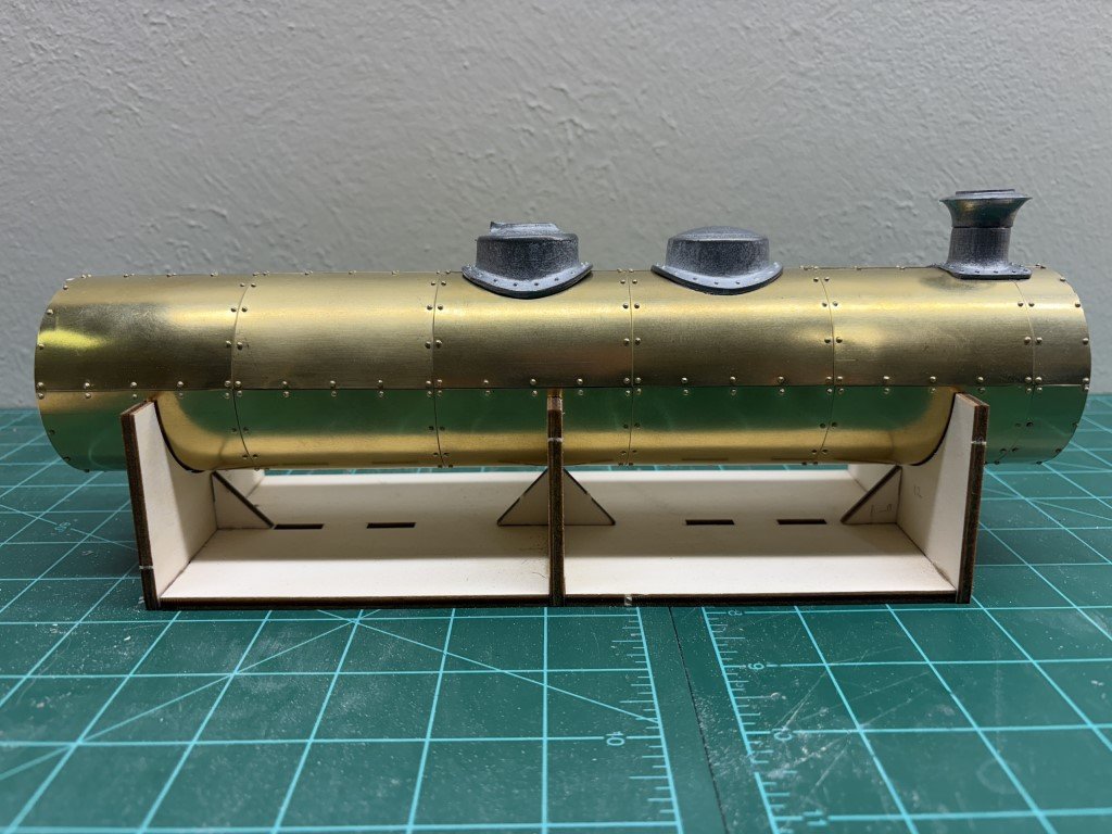
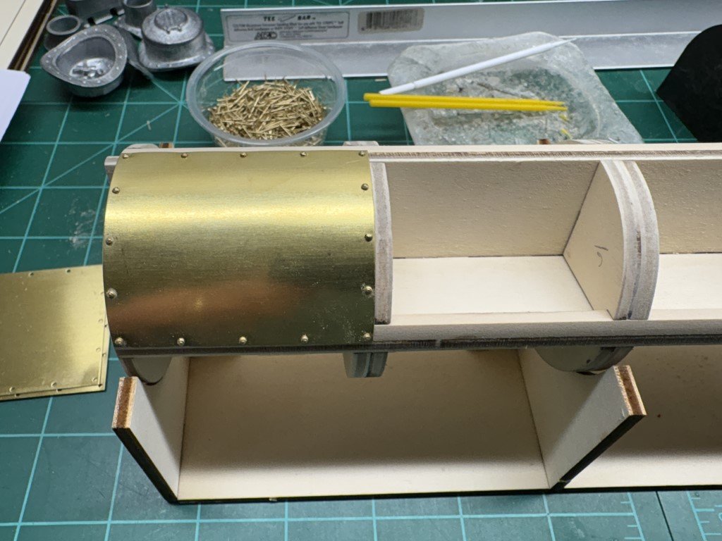
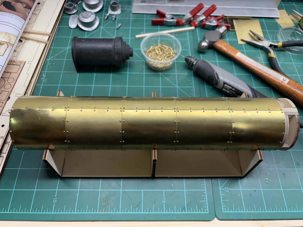
The amount of work putting on the last row of the larger plates was about the same as the other 3 rows in total. Each plate needed to be reduced in size - I don't think I over sanded the frame and didn't leave gaps between rows of plates, yet there was about 0.5 mm that needed to be removed from each plate. In some sense this is not bad when you think about how hard it is to manufacture the wooden disks and then provide brass plates that the sum total of lengths of 4 plates would exactly match the circumference of the boiler assembly! I adjusted the plate length using the Dremel sanding tool and the mill file. The four smaller plates at the front went on smoothly. Once all the plates were attached, I had a small amount of overhang in the front that was removed with the mill file. Again the amount was not great considering that the five plates lengths needed to match the wooden frame length. I should note that the instructions said to not pin / nail the front of the small plates. I believe this is because the kit comes with adhesive yellow stripes that go around the boiler and one is right at the end of the brass plate. The adhesive stripe would not work well on top of the nail heads. I put the nails in as I will not be making use of the adhesive tape. Next I have begun to fit and attach the soft meta castings to the boiler: The outward appearance of these castings are really nice. Each needed some adjustment at their base in order to match the diameter of the boiler. Again the Dremel with a (larger) sanding drum is getting some good usage. Related, the nails securing the brass plates under each casting are to be removed when the castings are attached. I have removed some, but others have been stubborn so they have been ground down instead.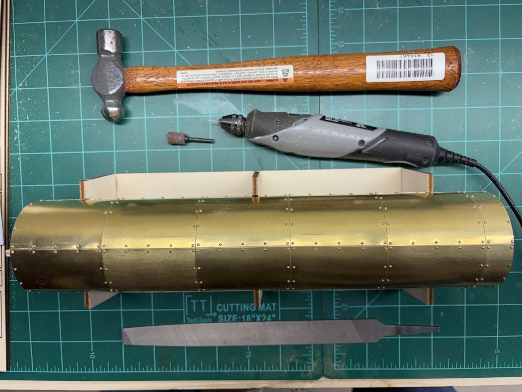
- 33 replies
-
- 14
-
-
-
BR-18 Locomotive by Greg Davis - OcCre - 1/32
Greg Davis replied to Greg Davis's topic in Non-ship/categorised builds
Today I began attaching the brass boiler plates. The kit comes with a pretty significant number of pre-drilled brass rectangles: The black object is a bending tool that OcCre markets - I had to buy this separately, it is turned wood and I'm surprised this isn't just included with the kit! The instructions show it in use and do indicate the brass should be bent on a cylinder with diameter 40mm. The boiler's wooden frame is 60mm in diameter. When the brass is bent on the smaller diameter it flexes back to fit the boiler nicely. I had thought about turning a bending tool myself, but wasn't sure if the 40mm diameter was a typo so I went ahead and purchased the tool. Note it has a couple of smaller diameter extensions on the right. These will be used later in the build and (unfortunately) the instruction booklet, does not indicate the diameters of the smaller shapes. So I guess it is advisable to have the tool! Here is the first plate attached - I think this is a required picture! The instructions indicate that the plates can just be nailed - glue not needed. I followed along, but with some apprehension. The instructions suggest using a pin/nail driver that they also market. I chose to not get that tool. Instead I have drilled very narrow pilot holes and used pliers and / or a small hammer to insert the nails. Currently, I have attached 3/4 of the large plates needed on the boiler - one more row to close it up and 4 smaller plates at the front will finish the work. One last note, the instructions provide guidance on how the builder can make / keep space open if installation of a smoke generator is desired. I will not be doing so, so I have not created an opening on top for such a feature.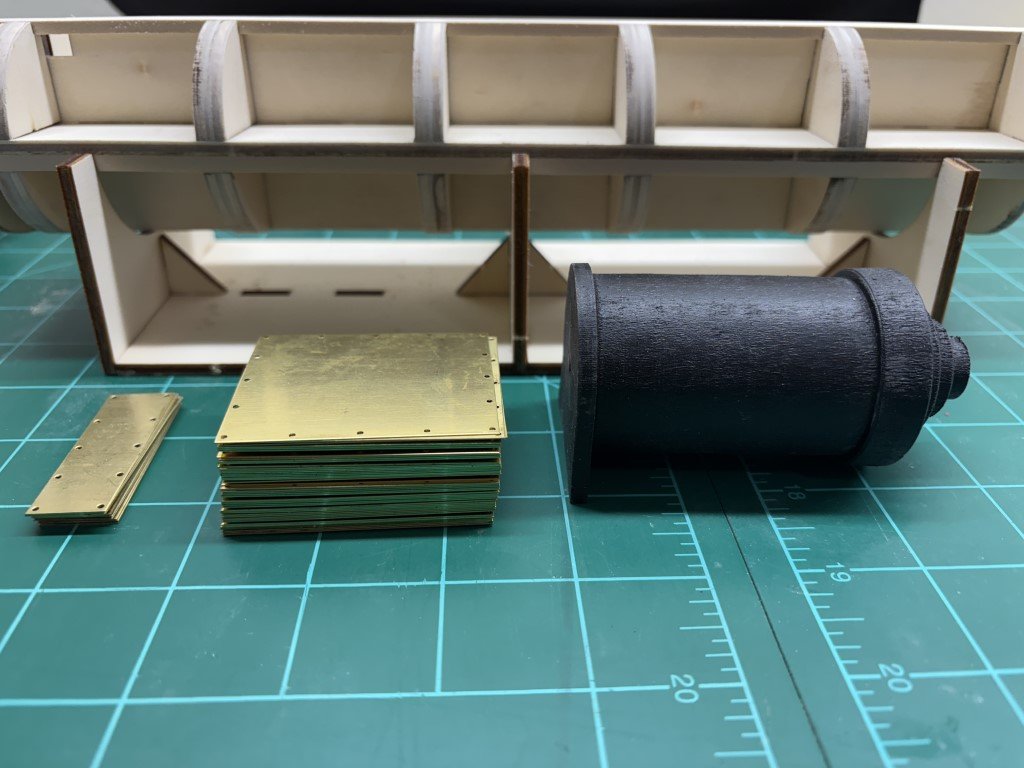
- 33 replies
-
- 14
-
-
BR-18 Locomotive by Greg Davis - OcCre - 1/32
Greg Davis replied to Greg Davis's topic in Non-ship/categorised builds
Thank you very much for this information! I had done some searching on the web with regard to color schemes hoping to find another bright color than green. It is not that I have anything against green - I was just looking for something different than the box cover. A blue based scheme had been on my mind and I was actually surprised to have found that it might be a possibility. If this hadn’t shown up I think I may have decided on a more standard black boiler with red underworks or just black. This is a nice looking locomotive and would probably make an attractive finished model in nearly any color. Greg