
TJM
-
Posts
358 -
Joined
-
Last visited
1 Follower

-
I have seen and tried many alternatives to Meshy, but none currently works as well for the things I have tried. It is amazing that Meshy can take pencil/ink drawings and return naturalistic 3D models!
-
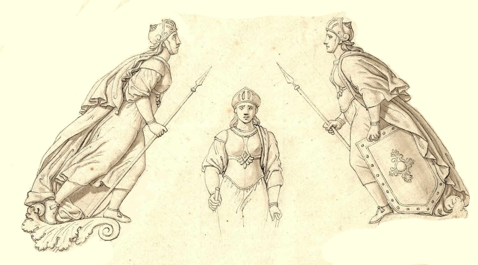
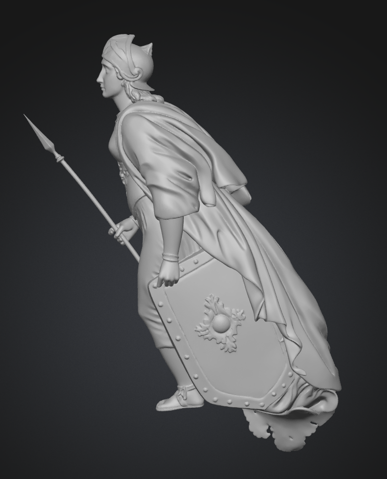
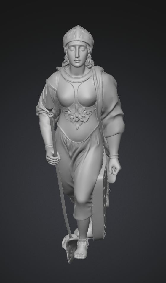
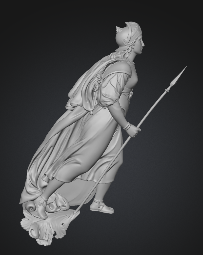
As @Chuck predicted a while back when this tread started, Meshy has now released the beta version of multi view for the Meshy 6 model. And it is fantastic 🙂 Here are the drawings of the figurehead of the frigate Rota from 1822, designed by the famous painter Professor C.W. Eckersberg: Feeding these three views in seperate images to Meshy gave me a near perfect model of the figurehead: So now we don't have to rely on extrapolation if we have several views, either from drawings or from photos from multiple angles 😄 BR TJM

-
 vvvjames reacted to a post in a topic:
Christiania 1774 by TJM – approx. 1:67-1:64 – Danish Light Frigate based on Vanguard Models HMS Sphinx
vvvjames reacted to a post in a topic:
Christiania 1774 by TJM – approx. 1:67-1:64 – Danish Light Frigate based on Vanguard Models HMS Sphinx
-
Agree, they are very nice.
-
westwood reacted to a post in a topic:
Christiania 1774 by TJM – approx. 1:67-1:64 – Danish Light Frigate based on Vanguard Models HMS Sphinx
-
TJM reacted to a post in a topic:
Christiania 1774 by TJM – approx. 1:67-1:64 – Danish Light Frigate based on Vanguard Models HMS Sphinx
-
 TJM reacted to a post in a topic:
Christiania 1774 by TJM – approx. 1:67-1:64 – Danish Light Frigate based on Vanguard Models HMS Sphinx
TJM reacted to a post in a topic:
Christiania 1774 by TJM – approx. 1:67-1:64 – Danish Light Frigate based on Vanguard Models HMS Sphinx
-
ccoyle reacted to a post in a topic:
Christiania 1774 by TJM – approx. 1:67-1:64 – Danish Light Frigate based on Vanguard Models HMS Sphinx
-
Arthur Goulart reacted to a post in a topic:
Christiania 1774 by TJM – approx. 1:67-1:64 – Danish Light Frigate based on Vanguard Models HMS Sphinx
-
Nick 843 reacted to a post in a topic:
Christiania 1774 by TJM – approx. 1:67-1:64 – Danish Light Frigate based on Vanguard Models HMS Sphinx
-
KurtH reacted to a post in a topic:
Christiania 1774 by TJM – approx. 1:67-1:64 – Danish Light Frigate based on Vanguard Models HMS Sphinx
-
brunnels reacted to a post in a topic:
Christiania 1774 by TJM – approx. 1:67-1:64 – Danish Light Frigate based on Vanguard Models HMS Sphinx
-
 TJM reacted to a post in a topic:
Chris Watton and Vanguard Models news and updates Volume 2
TJM reacted to a post in a topic:
Chris Watton and Vanguard Models news and updates Volume 2
-
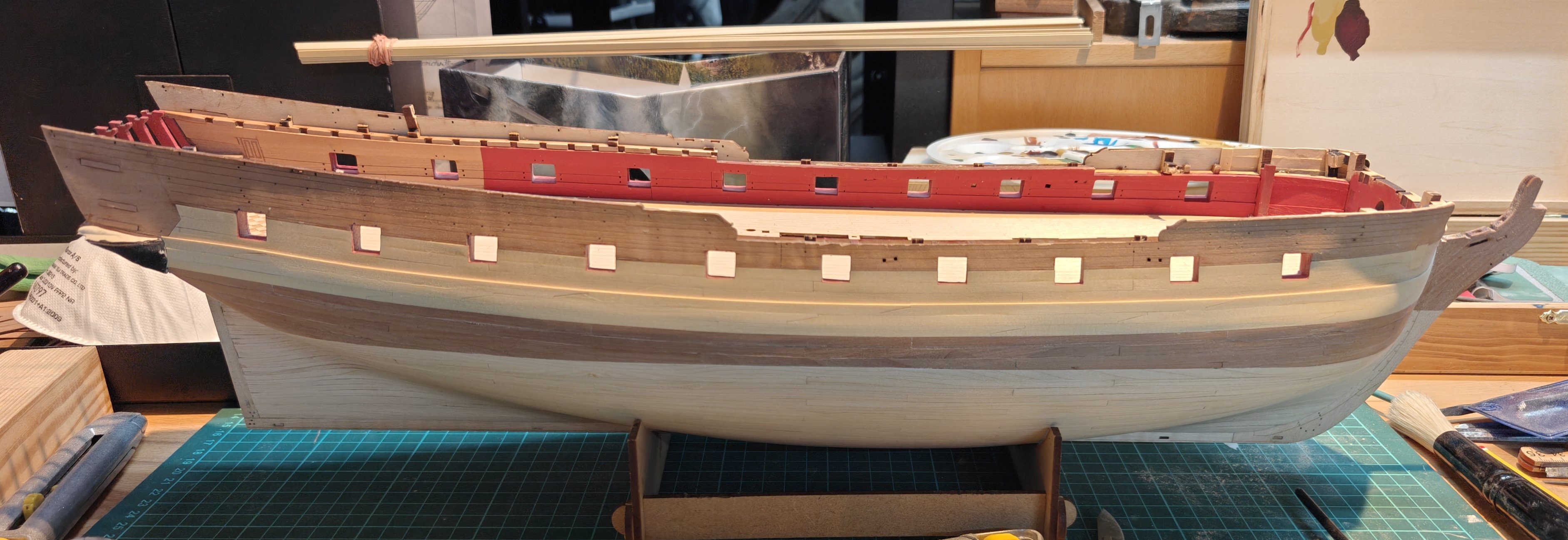
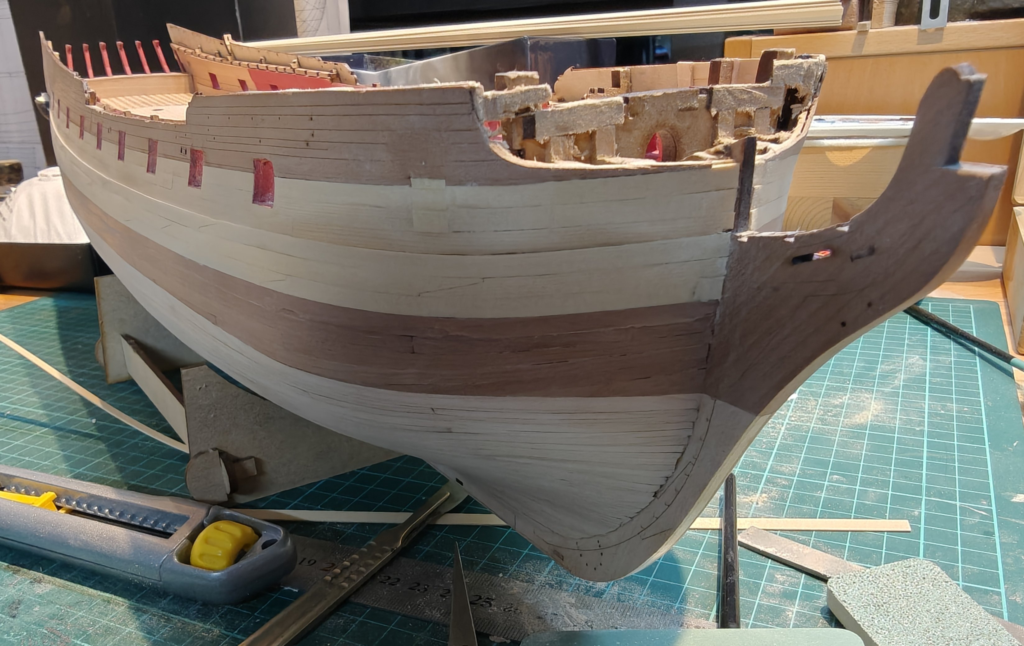
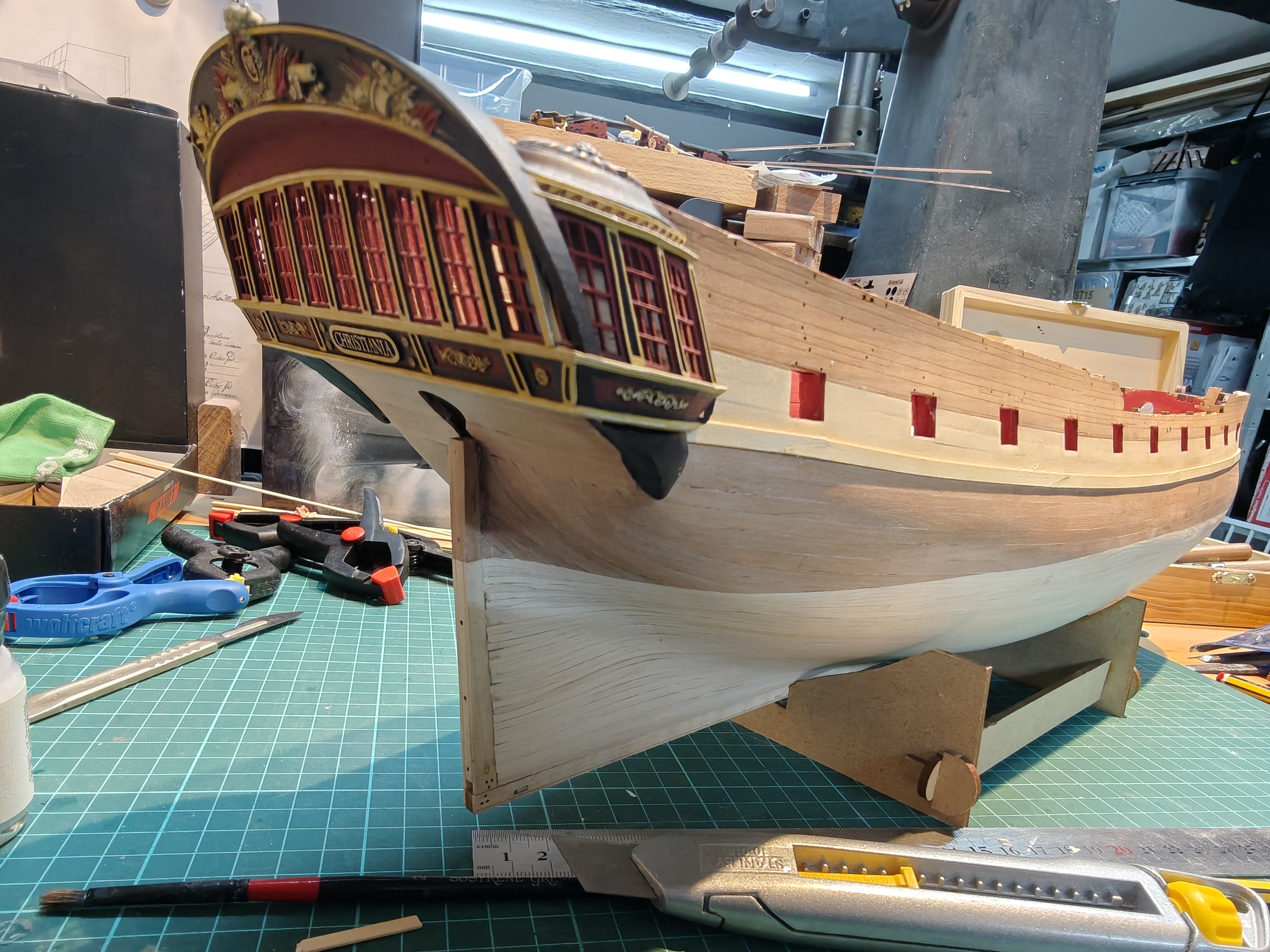
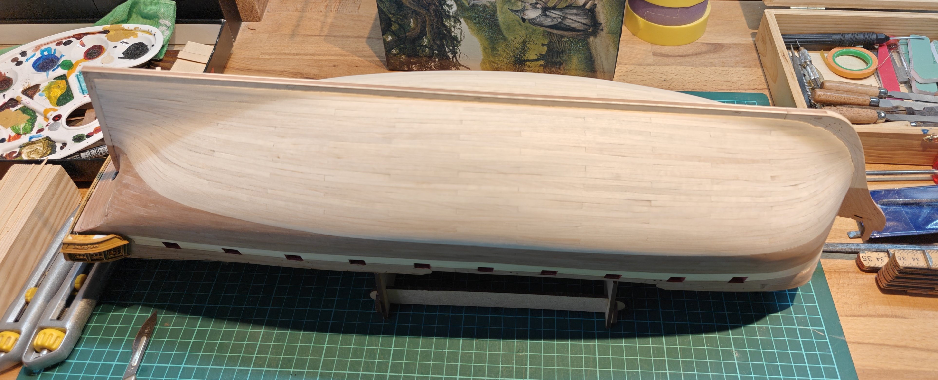
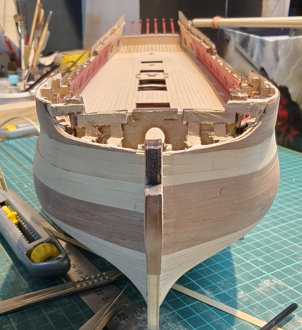
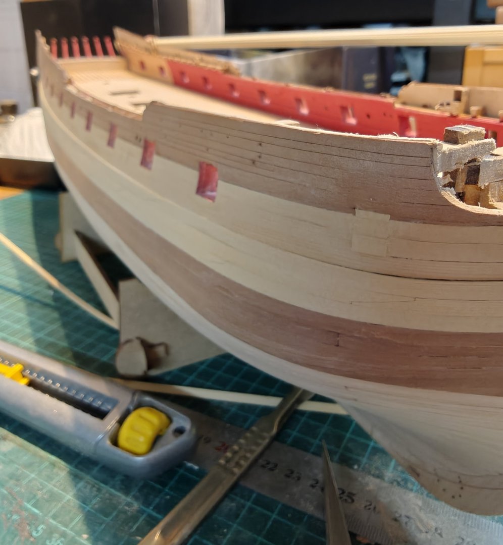
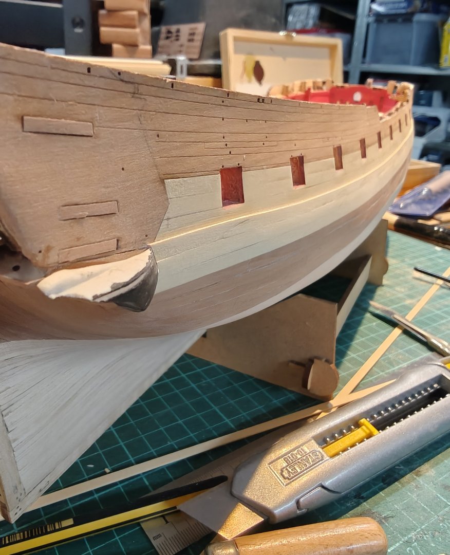
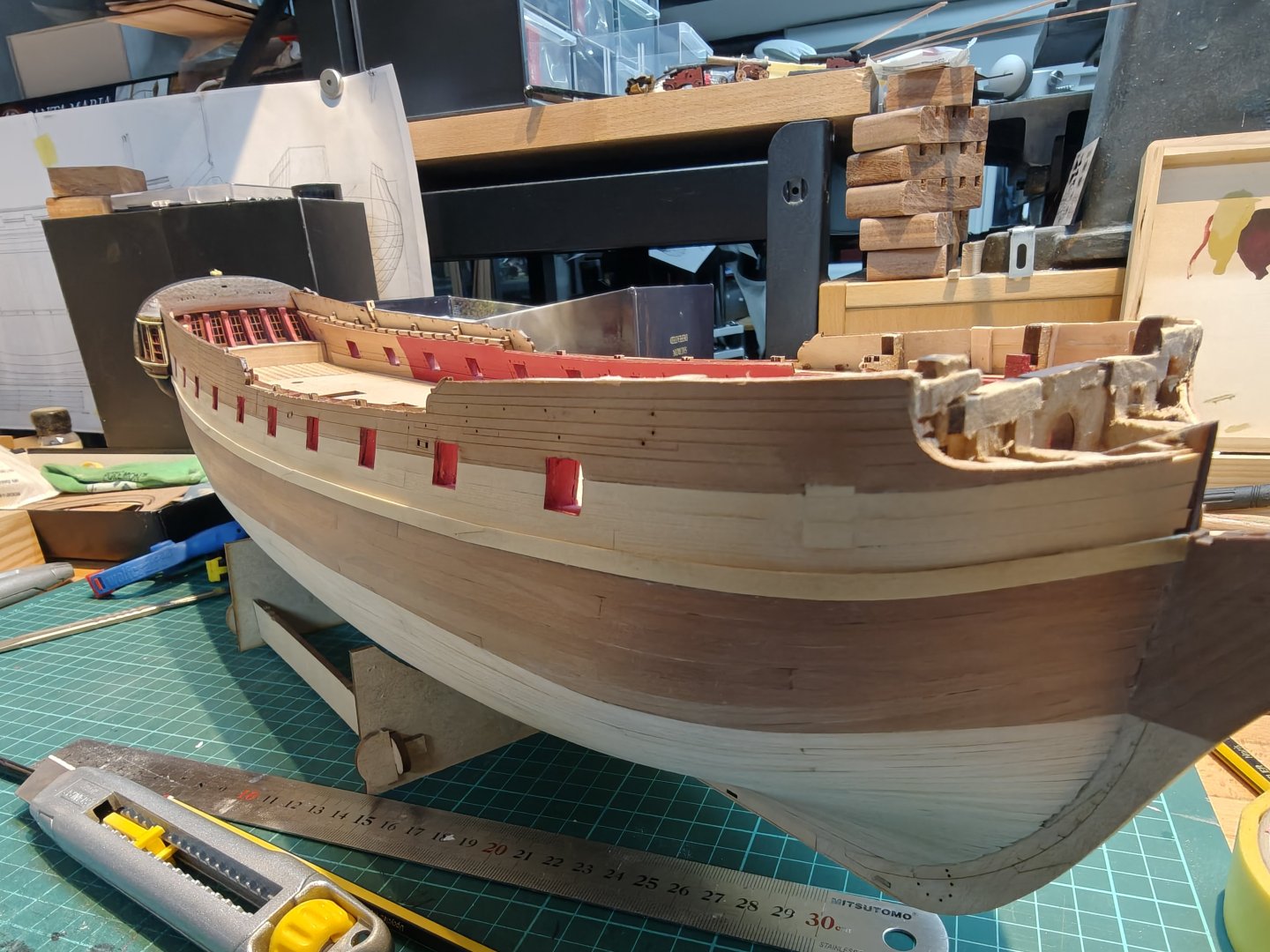
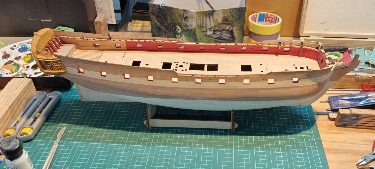
Log entry 36 - starboard wale done I added the two last yellow ceder wale strips (scarfed) and a pear strip (butted) and sanded it to blend into the second planking at the lower edge, while keeping the full 0.8 mm at the upper edge - except at the bow where I took it down to almost nothing. This seems to work well enough, though it would of course have been better to use one layer of 1.6 mm for the planking. The lower blend edge is visible if you look for it, but it disappears at a 50 cm viewing distance. It will have to do. Here's the 'new look': I think I am happy with my decision on how to do the wale and the colours. Still a bit of sanding needed, but I'll pass over the whole hull again after the port side wale has been added. BR TJM


- 144 replies
-
- 6
-
-
- Christiania
- Vanguard Models
- (and 1 more)
-
TJM reacted to a post in a topic:
HMS Portland 1770 by westwood - Portland Scale Ship Co. - 1:48 - 50 gun 4th rate
-
TJM reacted to a post in a topic:
HMS Sphinx 1775 by En-Dan - Vanguard Models - 1:64
-
TJM reacted to a post in a topic:
HMS Portland 1770 by scrubbyj427 - 1:48 - 4th rate 50-gun ship
-
TJM reacted to a post in a topic:
Christiania 1774 by TJM – approx. 1:67-1:64 – Danish Light Frigate based on Vanguard Models HMS Sphinx
-
TJM reacted to a post in a topic:
Christiania 1774 by TJM – approx. 1:67-1:64 – Danish Light Frigate based on Vanguard Models HMS Sphinx
-
TJM reacted to a post in a topic:
Christiania 1774 by TJM – approx. 1:67-1:64 – Danish Light Frigate based on Vanguard Models HMS Sphinx
-
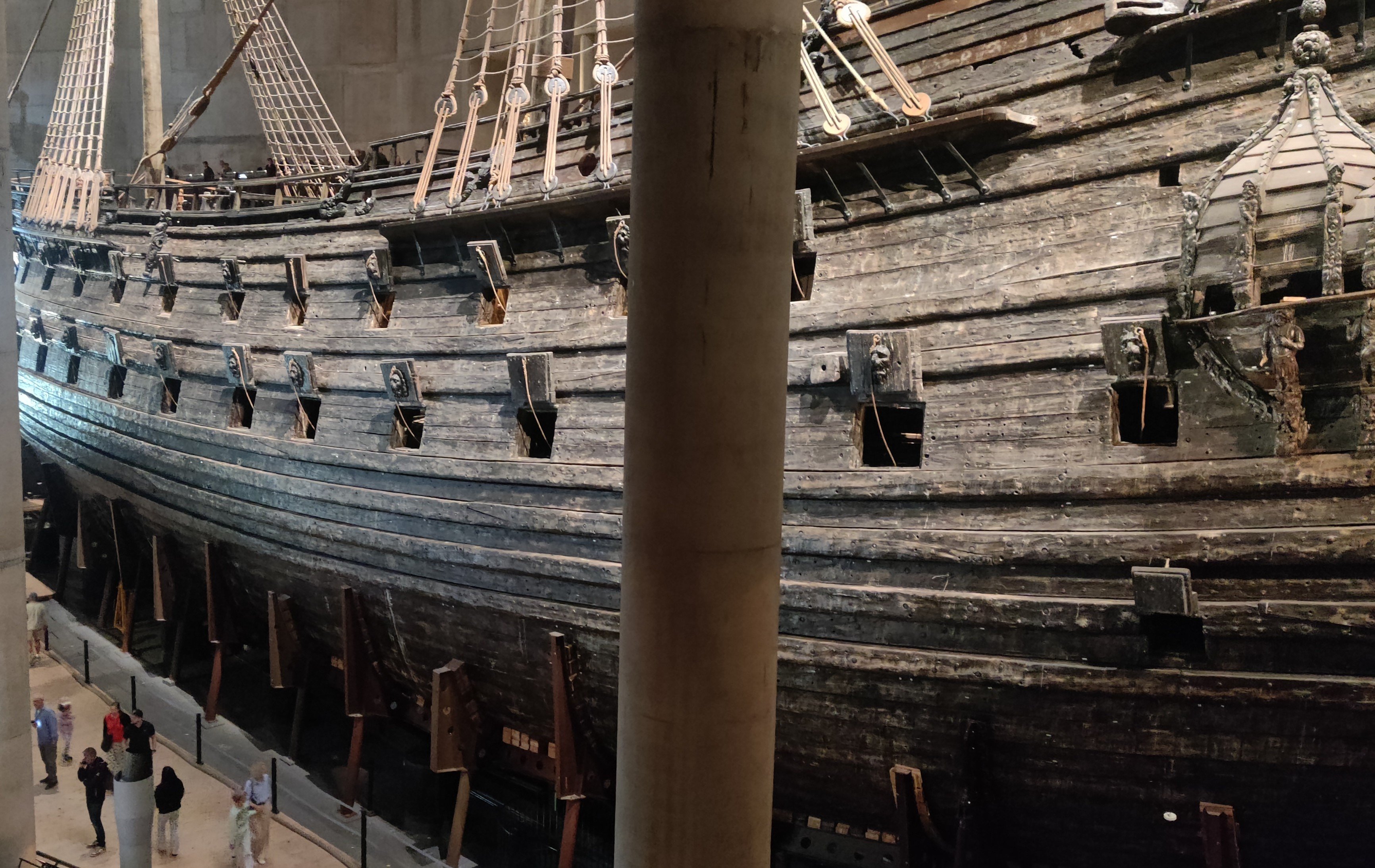
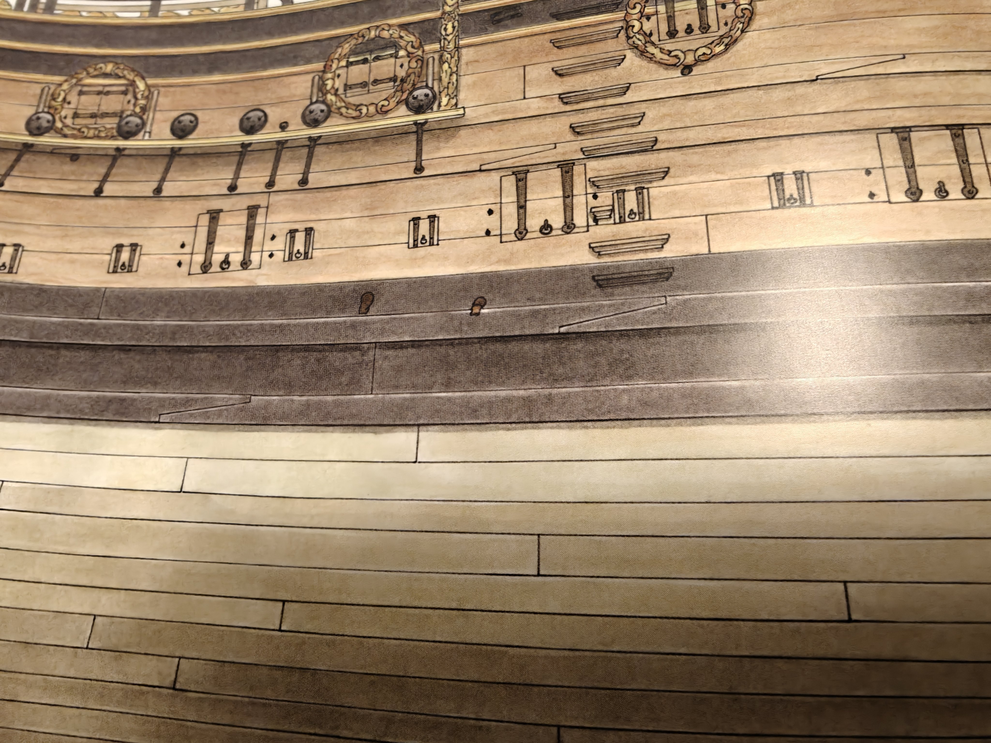
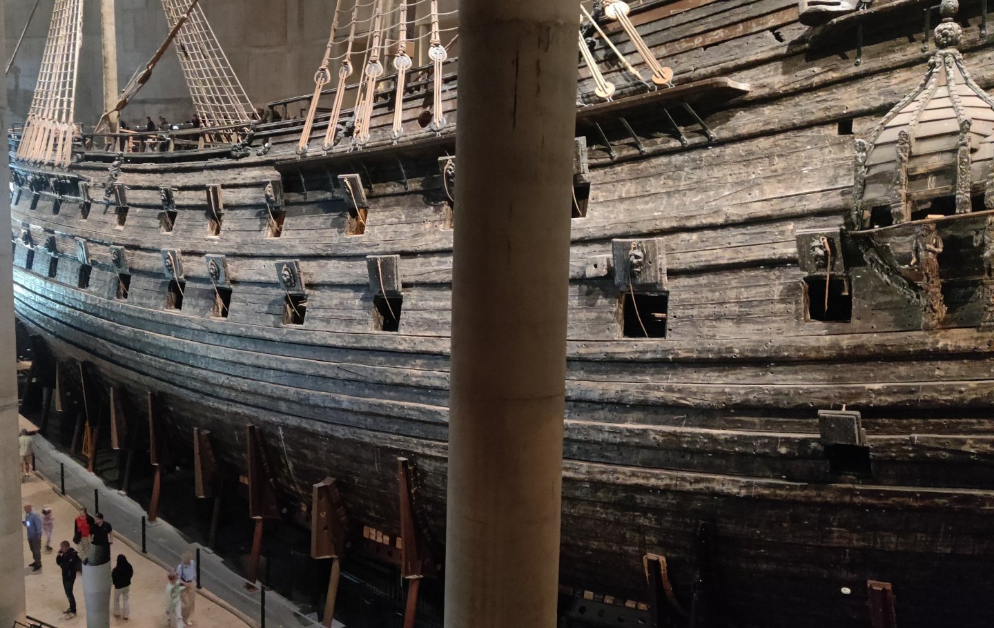
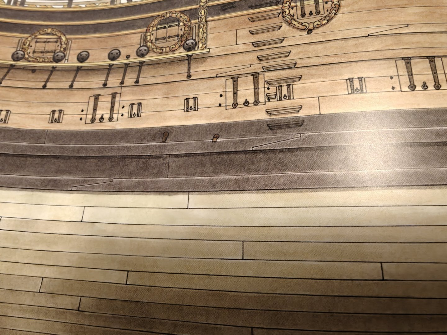
I am by no means any sort of expert, but it is my understanding that the wales are there to prevent sagging of the gundeck, and perhaps also stiffen the hull to prevent keel breaking. Having butt joints would, I think, largely remove the lateral strength, while the scarf joints allows the sections of the wale planks to pass load to the neighboring sections. If anyone has a better, or different explanation, I would welcome the input! It is well documented that the thicker wale planks were scarf joined: Here is a shot of Vasa showing this: And here is a drawing by Richard Endsor of HMS Tyger: And here is a model of Bornholm at Krigsmuseet in Copenhagen (that I use for a lot of the colour inspiration for Christiania), showing scarfed wales: In general, many models at Krigsmuseet show this for the wales - but some don't. There are also sources that does not show scarfed wales, like Boudriot's the 74 gun ship. Here the 'thick stuff' is made of longer sections ot seems, but are still shown as butt joined.
- 144 replies
-
- 6
-
-
-
- Christiania
- Vanguard Models
- (and 1 more)
-
TJM reacted to a post in a topic:
Mary Rose by Baker - scale 1/50 - "Your Noblest Shippe"
-
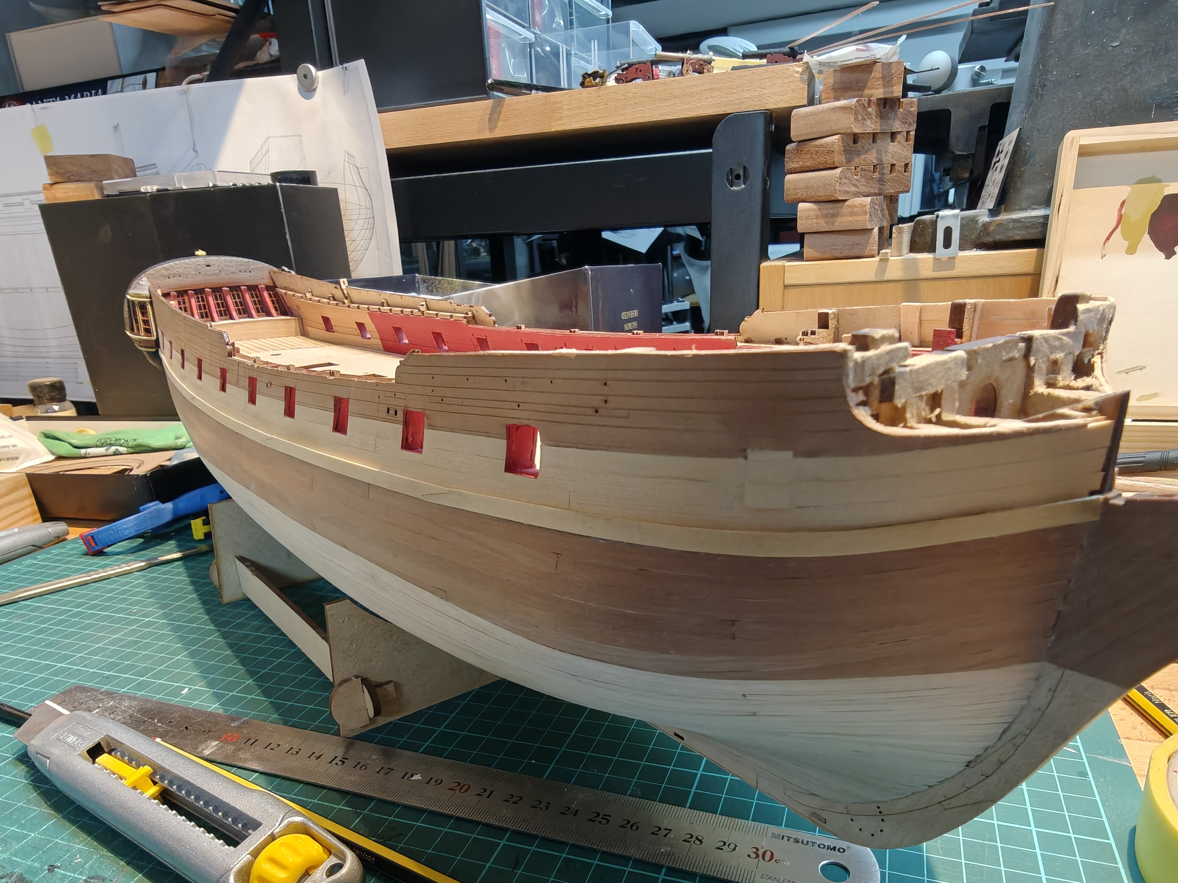
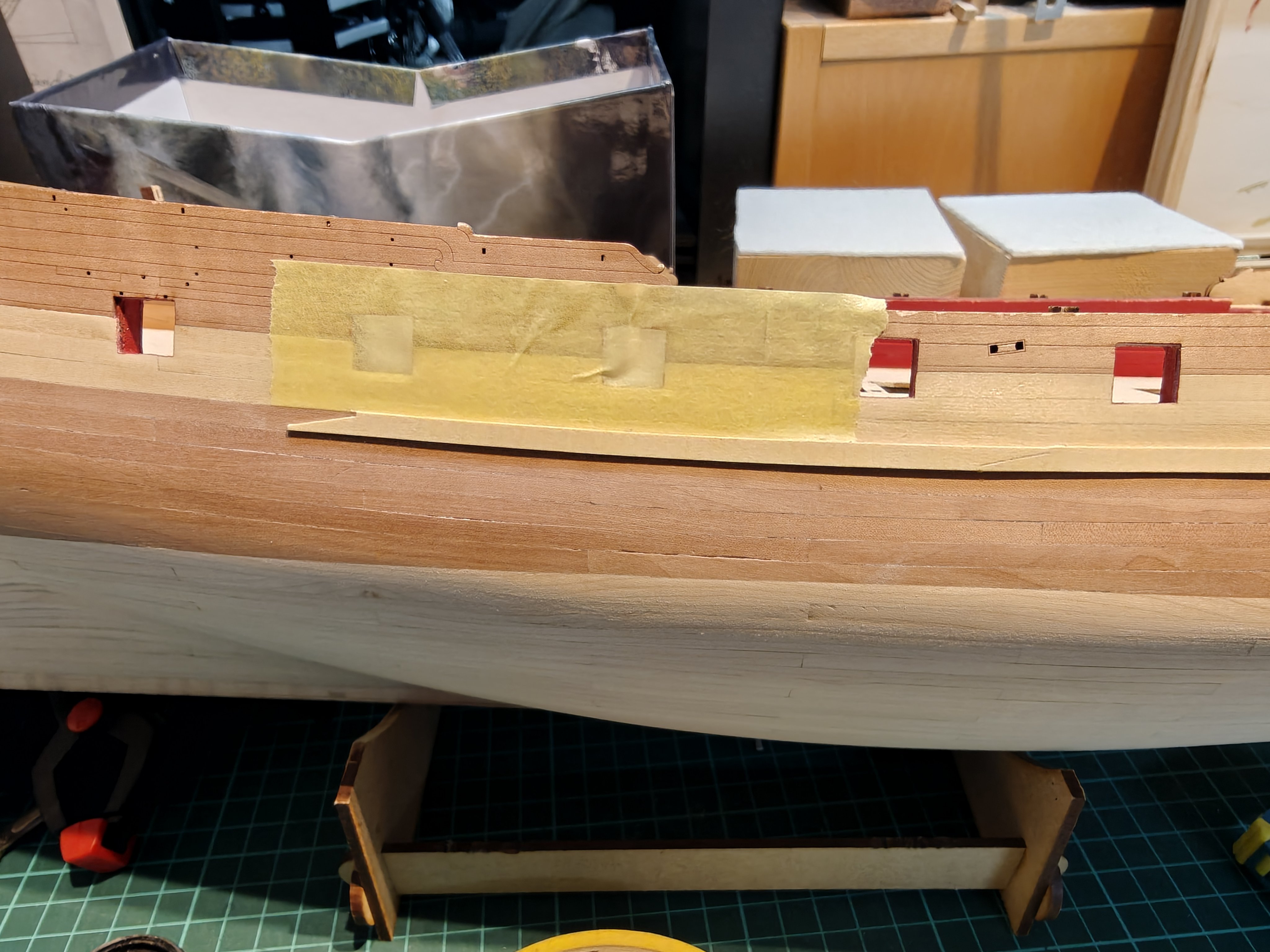
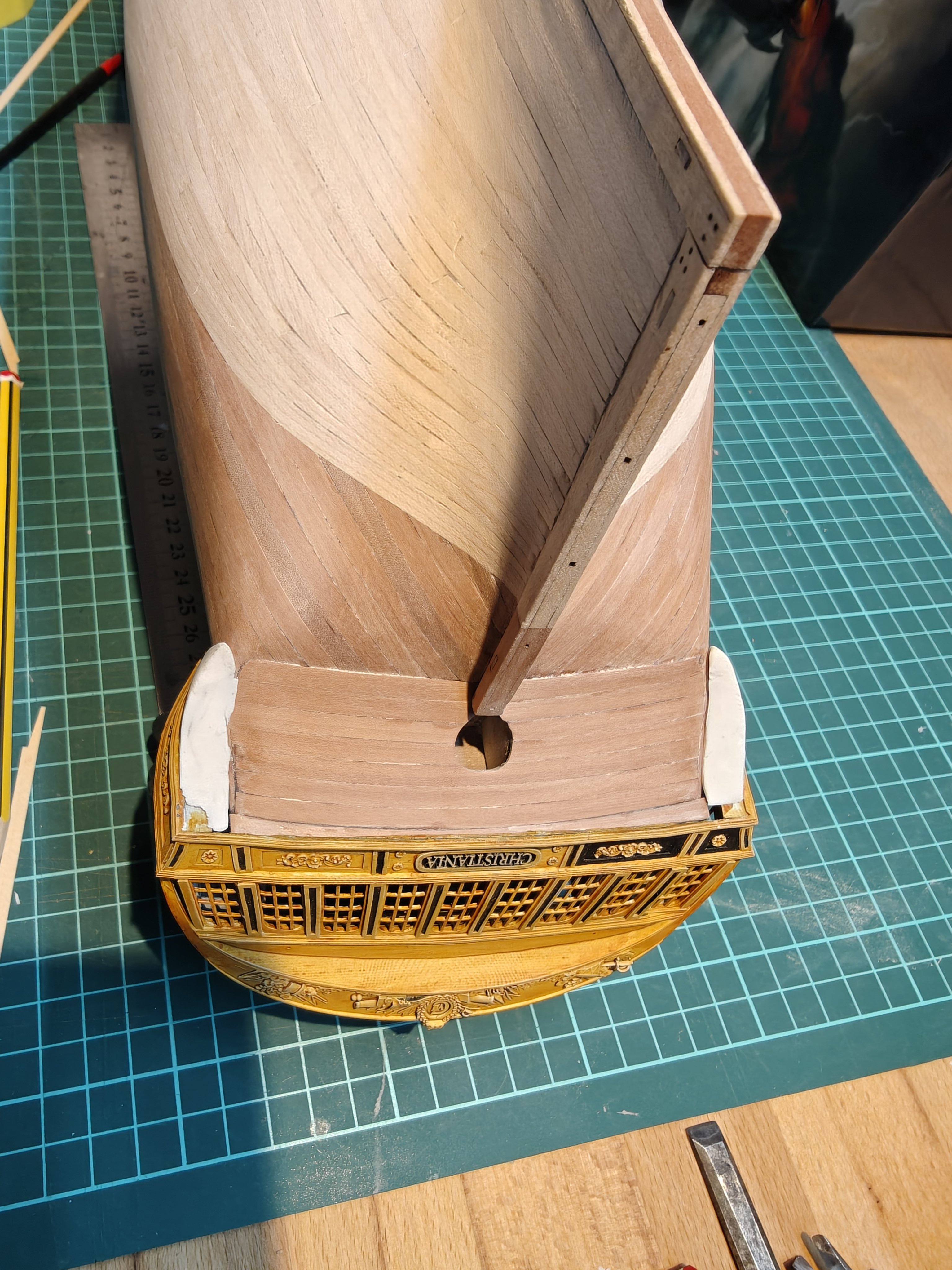
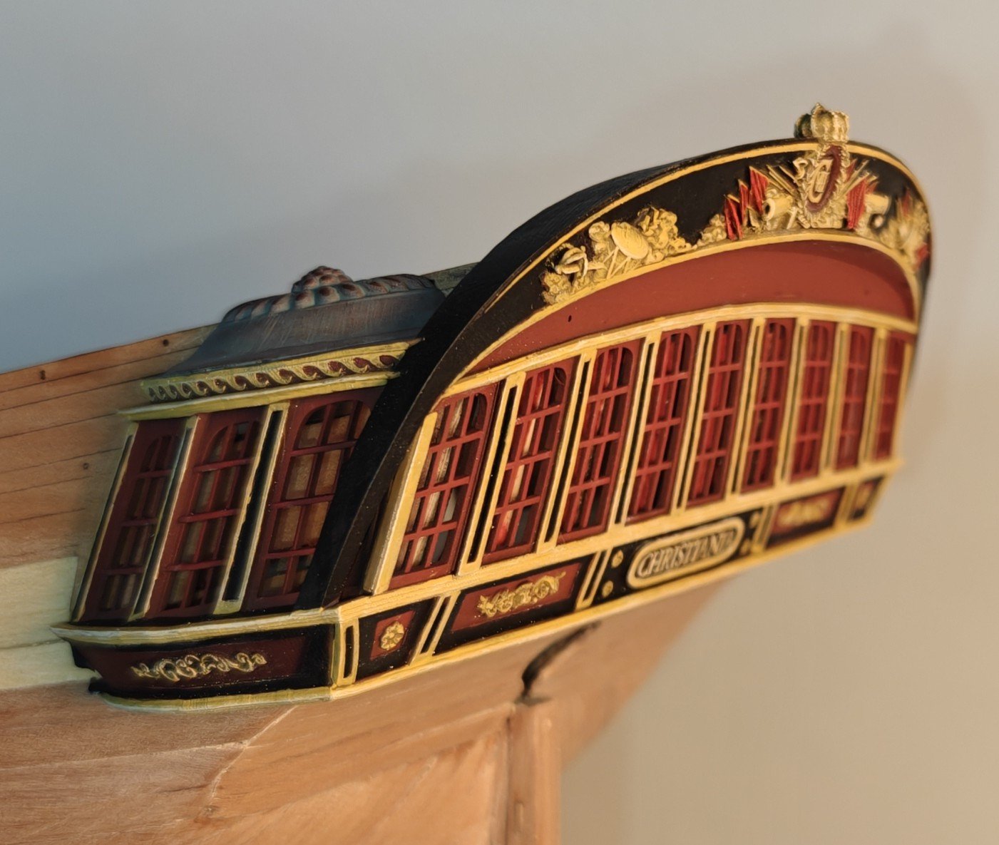
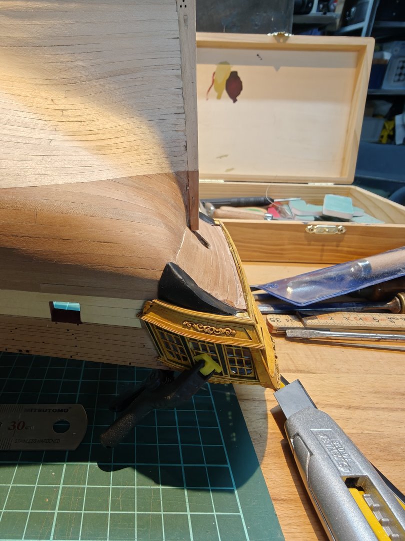
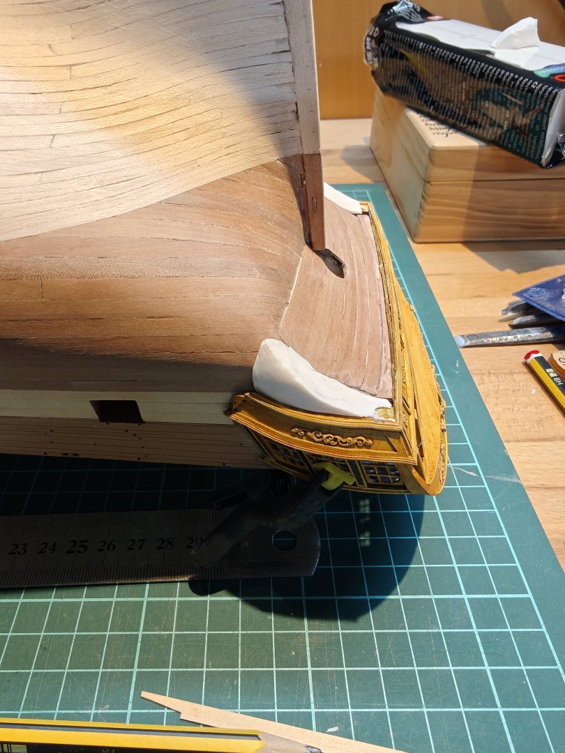
Log entry 35 - lower gallery parts and starting on the wales I was not happy with my wooden gallery bottom, so I though I would try sculping it from polymer clay (Fimo). I was able to get a better fit and sharper edges, so I went forward with this solution. I painted them black and attached them with CA: Don't worry about the nasty gaps between the wood and the clay, it will be covered up by a decorative element that I will probably design and 3D print, to match the rest of the stern decorations. The reason I am gluing thes on now is that I want the wale planks to be completely snug against them, so this is needed to move on with the wales. I have decided to plank with 3 yellow ceder planks and then one or two pear planks and then leave the ridge at the top and (almost?) blend it into the planking at the bottom. The pear wood is then where the hull would have been painted black, giving a compromise between showing as much wood as possible, while still showing the pattern the paint would have given the hull. To make it more interesting (and realistic) I am doing the the wale planks with simple scarf joints, instead of butt joints: The scarfs will be very subtle once sanded, as there is very little grain or colour variation in the ceder strips, but I think it is a nice small addition. They are not too difficult to make. I couldn't resist popping on the painted stern to see how it would look (and check the fit, which is good!): Will be back with more wale planking soon 😁 BR TJM


- 144 replies
-
- 8
-
-
- Christiania
- Vanguard Models
- (and 1 more)
-
Fantastic carvings Matthias, as always really well done!
-
Nice deal! It is unlimited downloads, yes, but a fixed number of tokens per month to use. You get 1000 tokens, enough for 50 meshy 6 runs. For each run, you can re-run the prompt 4 times (so 5 total) and download all of them to have something to chose from.
-
Thanks you so much, guys! Really appreciate the feedback 😃 Yes, I believe I will be going the scratch route for most future builds. But I still have much to learn from this kit, but I feel that every time I complete a phase, I would be able to use that on a scratch build - I did not have confidence like that after Flirt, I needed more experience. I will be sorely tempted by Vanguard Models' future releases - while both Surprise and Agamemnon will be fantastic, I am really looking forward to see Chris do HMS Tyger. The ships from the period 1640-1690 has a wonderful aesthetic, I think, and I really want to see what a modern, full-blown VM treatment will look like. Luckily for me, that one is still a bit into the future! I also have Amati's Revenge 1577 stacked away (also designed by Chris Watton) and I plan to do this some day, but not sure when.
- 144 replies
-
- 2
-
-
- Christiania
- Vanguard Models
- (and 1 more)
-
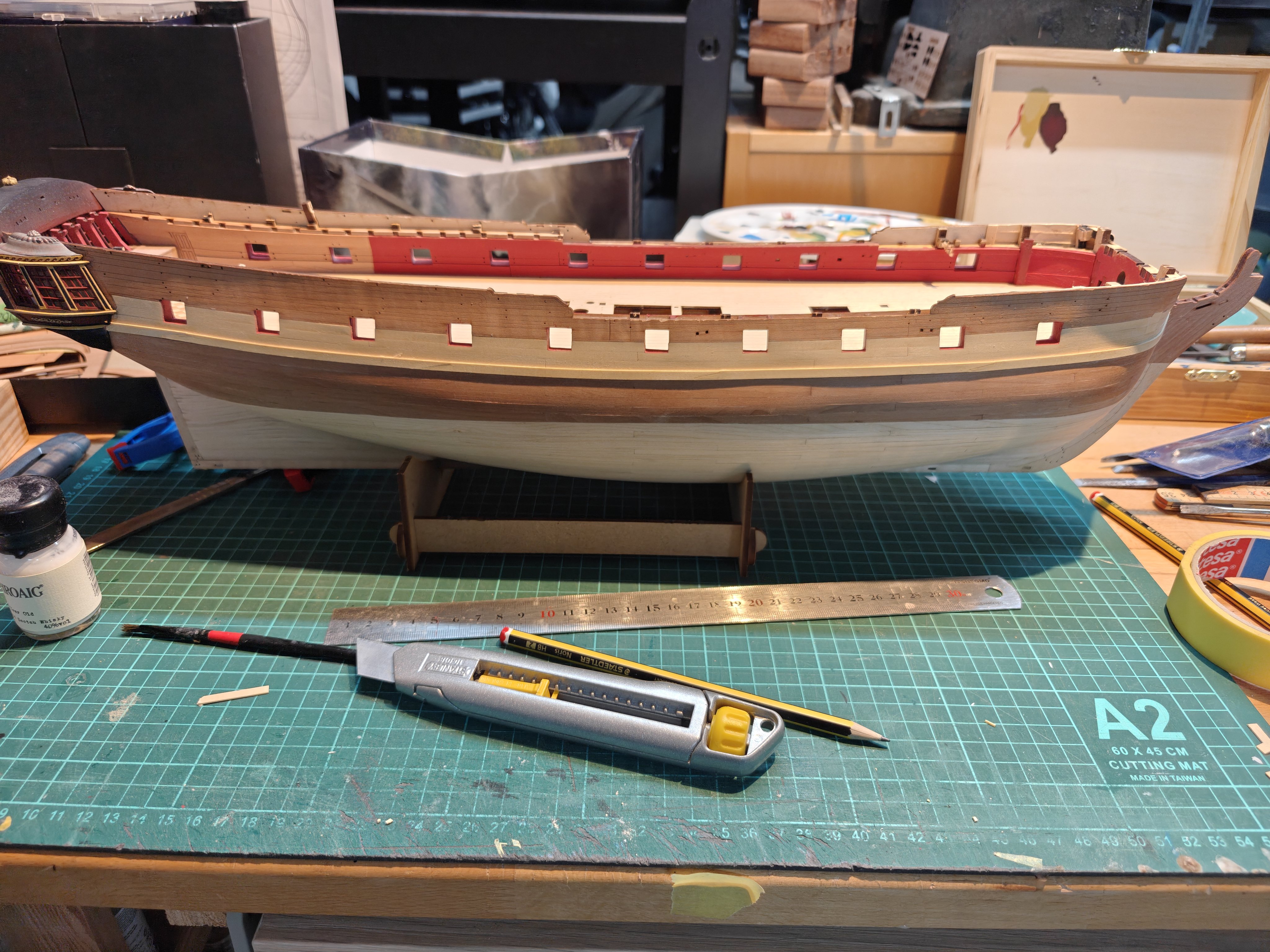
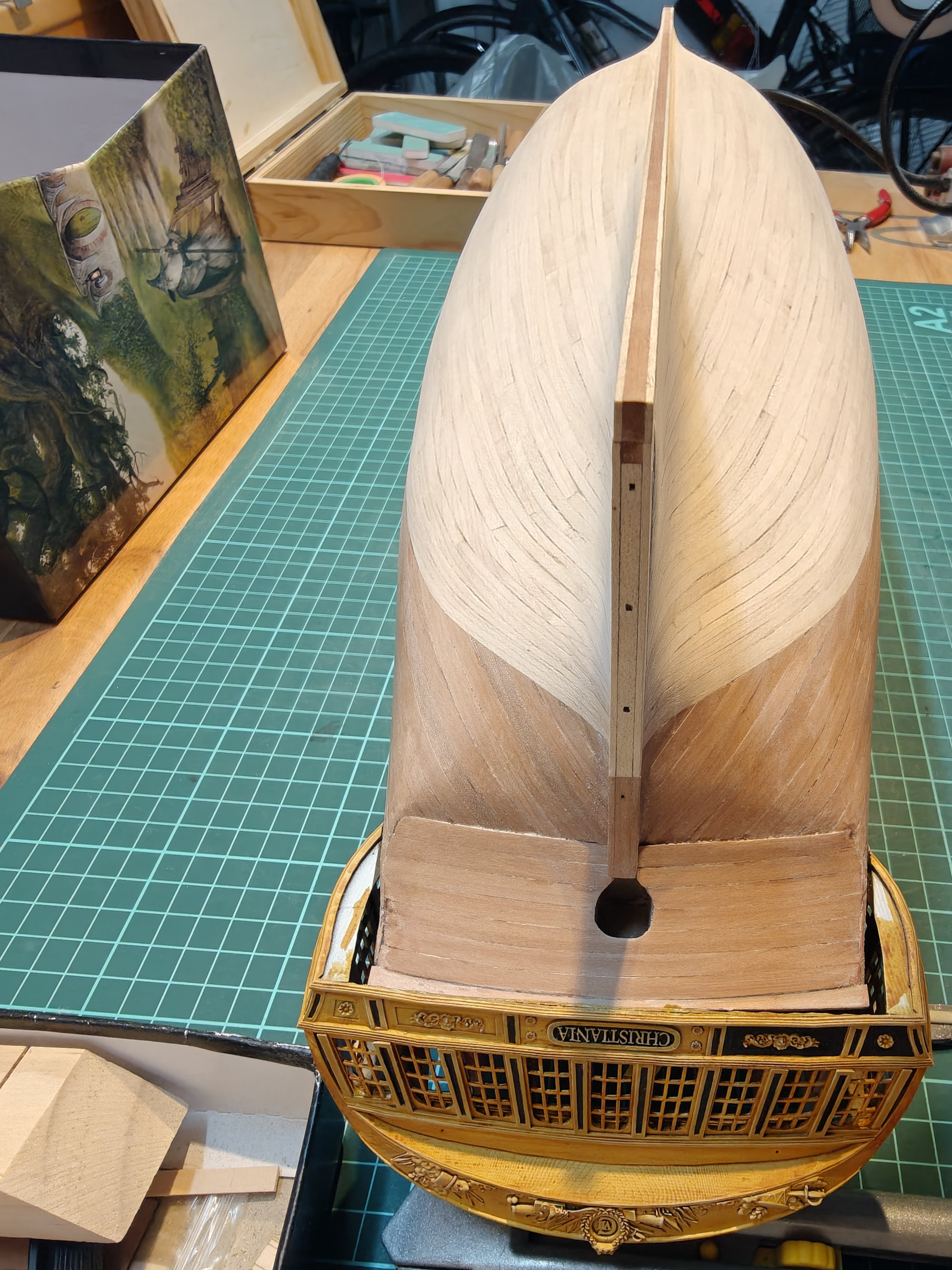
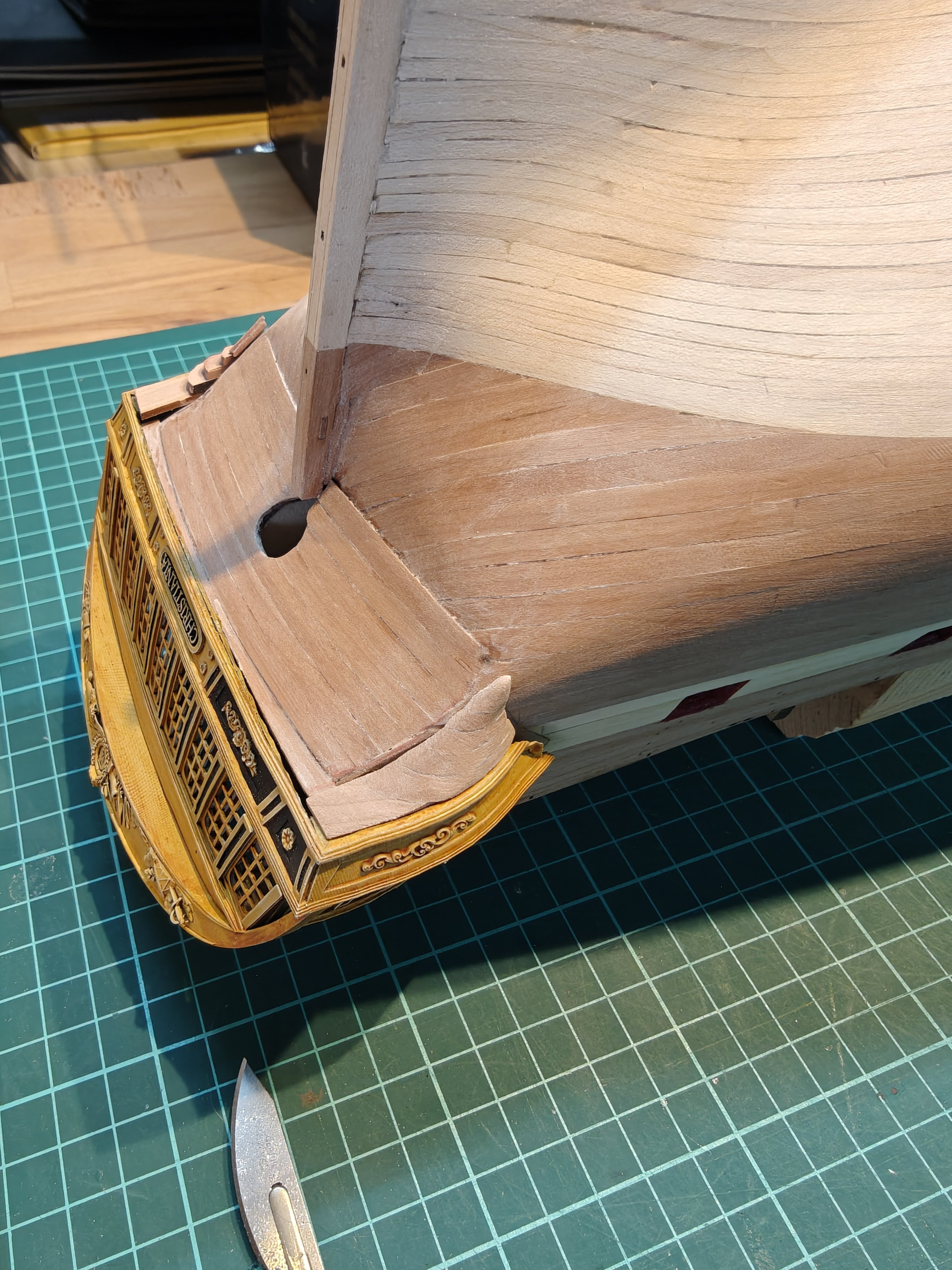
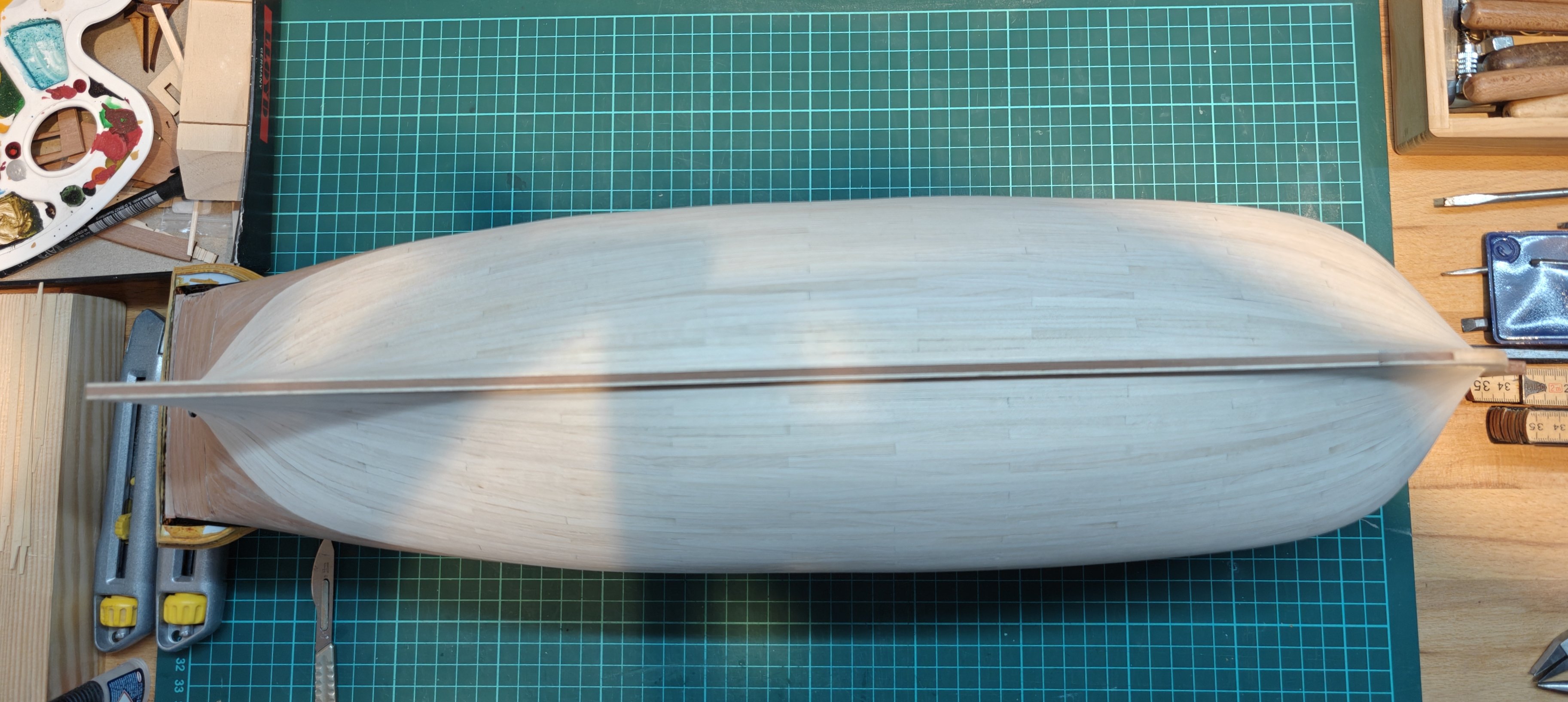
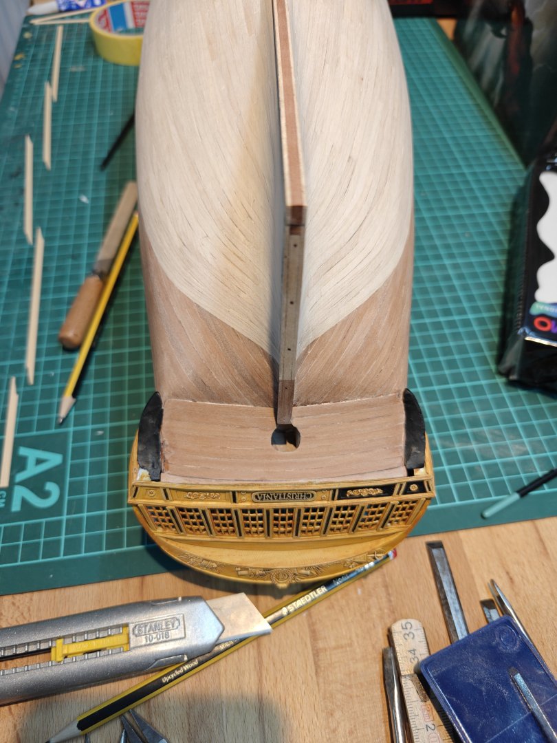
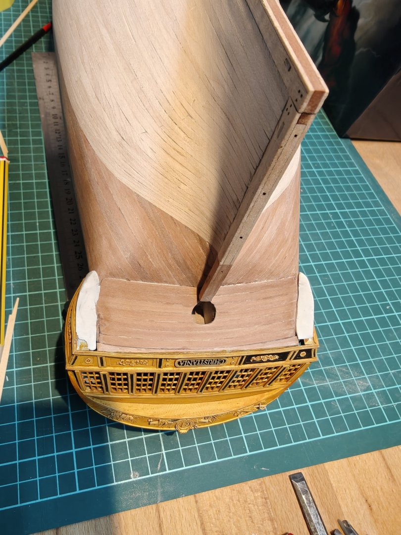
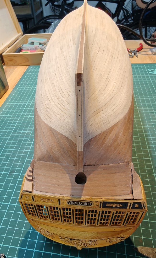
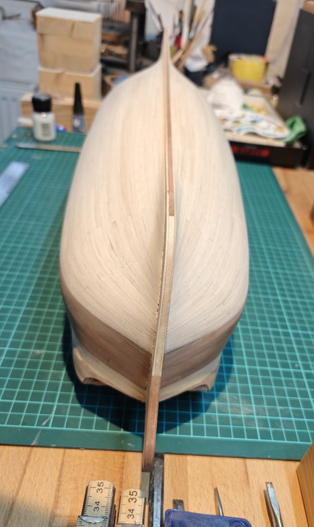
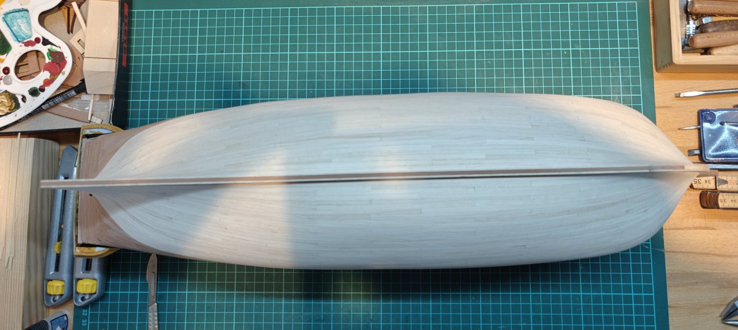
Log entry 34 - planking completed! And, just like that, the planking is complete! I have done the first sanding pass, and it is mostly good, just a few spots that need a bit more: This has taking me a very long time - almost 16 months since i began the second layer planking. Most of that time was obviously not spent on the model, ad I have been procrastinating by making Elben and drawing other ships i CAD, i have learned 3D printing and I have modelled the stern, the figurehead, a ship boat, many different cannons, etc. I am happy I pushed to the planking finish line, as I look very much forward to the next stage of the build. I am planning the wale planking and I am modelling the lower galleries - this is also why I have loosely fitted a reject stern print, as I need it to fit the lower gallery parts: It needs a bit more work, but I will be filing the gap with filler and covering it with a decorative element. And then the workspace got that cleaning 😅. BR TJM


- 144 replies
-
- 11
-
-
- Christiania
- Vanguard Models
- (and 1 more)
-
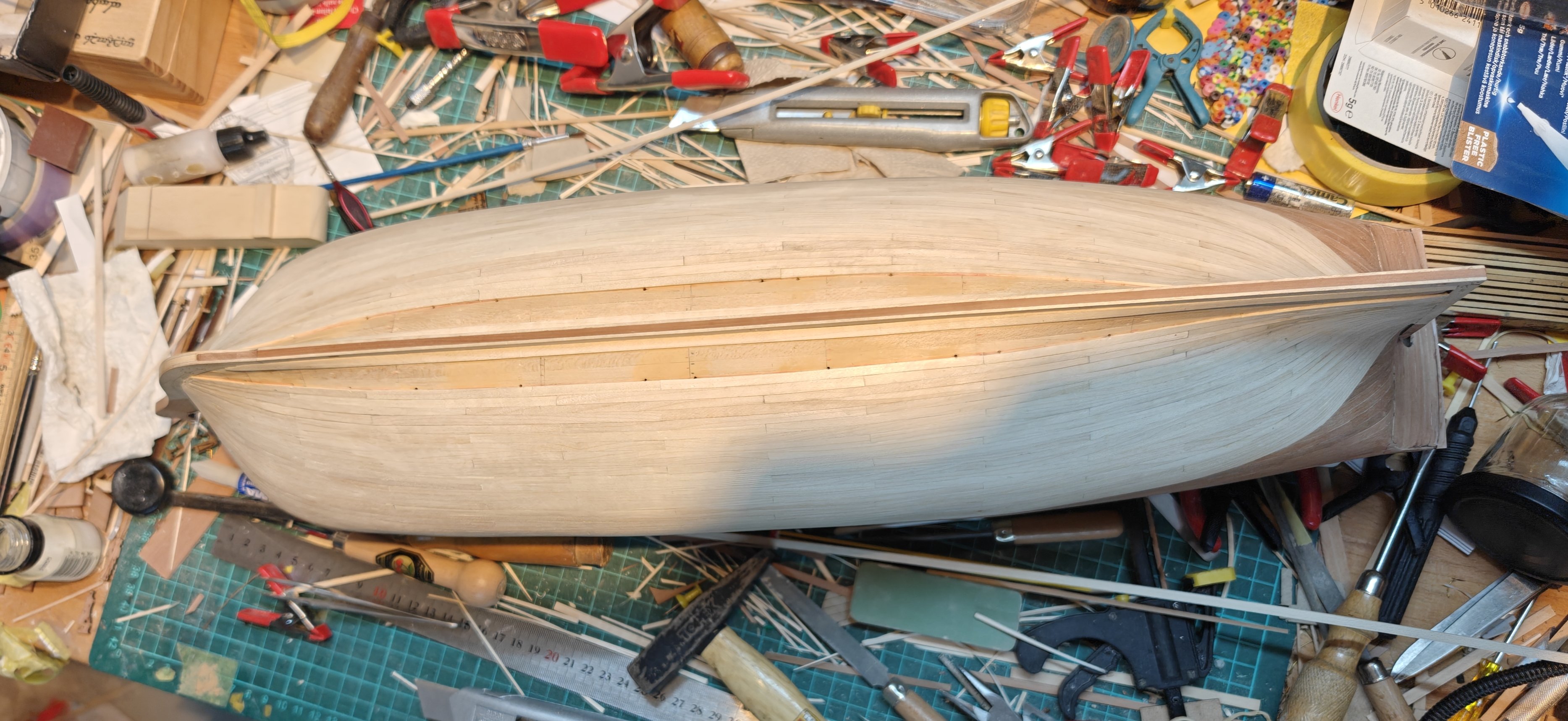
Only 6 planks missing now! Then a bit of gap repair in a few spots and then a lot of sanding. (And a workbench cleanup! 🤪)

- 144 replies
-
- 10
-
-
- Christiania
- Vanguard Models
- (and 1 more)
-
I also think what you have looks very good. I see the point of the end grain - a miter connection would have been ideal I guess, but personally, I would be happy with the joint you have. I like the wood look, as long as it does not have obvious laser char, but you always take care to remove this so all good! Whatever you go for, it will look great 😄
-
Nice! Do you always brush it on, also on the large surfaces like the main hull, or do you ever use an airbrush? Also, what varnish are you using? It looks great!
-
Yes, this is also what I conclude based on the evidence I have seen so far. And yes, no matter what, this build will not be a truly faithful representation of Christiania - it cannot be with me adapting the Sphinx kit. All of the deck furnishings will be 1:1 the Sphinx setup. So I guess I can take the liberties I want, but I still have to decide what I prefer 😅 The comment about the painting of the ships comes from Danske Orlogsskibe 1690-1860 (a fantastic book!): This translates to: In Gerner’s period, the painting of ships was introduced in the Danish navy. This came about almost through a private initiative, as the commander of Sophia Frederica in 1781, A. F. Moltke (1748–1820), at his own expense had his ship painted. The following year, the commander of the Indfødsretten, in connection with sailing to the Mediterranean, requested permission to do the same. The commander of Holmen had now come to the conclusion that painting was more preservative than the ordinary tallowing that had previously been used, and therefore had the painting of all Danish ships of the line carried out.¹¹ Previously, the ships had been “blacked” with a mixture of thin tar and soot, something that gave the ships a dark brown, almost blackish appearance. According to the regulations, this applied only to ships of the line, while the frigates were occasionally treated with pine pitch. When the blacking and pitch-coating took place, care was taken to cover tarpaulins over the “externally painted ship ornaments” in order to avoid blackening them.¹² Reference 11 is to a text by F.C.Kaas published posthumously in 1843 who recounts the work that was done while he was Chief of Holmen (the Navy shipyard in Copenhagen) from 1781-92

- 144 replies
-
- 1
-
-
- Christiania
- Vanguard Models
- (and 1 more)
-
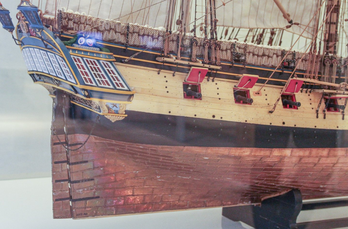
I think this contemporary model of Fyen (1736) shows how it would have been. Even if it is some 40 years earlier than Christiania: We know that the ships were not painted between the upper decoration and the lower wale until sometime in Gerner's period, so after Christiania was built - I did not know this when I decided to emulate the painted yellow band with the cedar. This is why I am now considering making it the main 'wood' colour for the hull instead, by using it for the wale as well.


- 144 replies
-
- 6
-
-
- Christiania
- Vanguard Models
- (and 1 more)