
TJM
-
Posts
362 -
Joined
-
Last visited
Content Type
Profiles
Forums
Gallery
Events
Everything posted by TJM
-
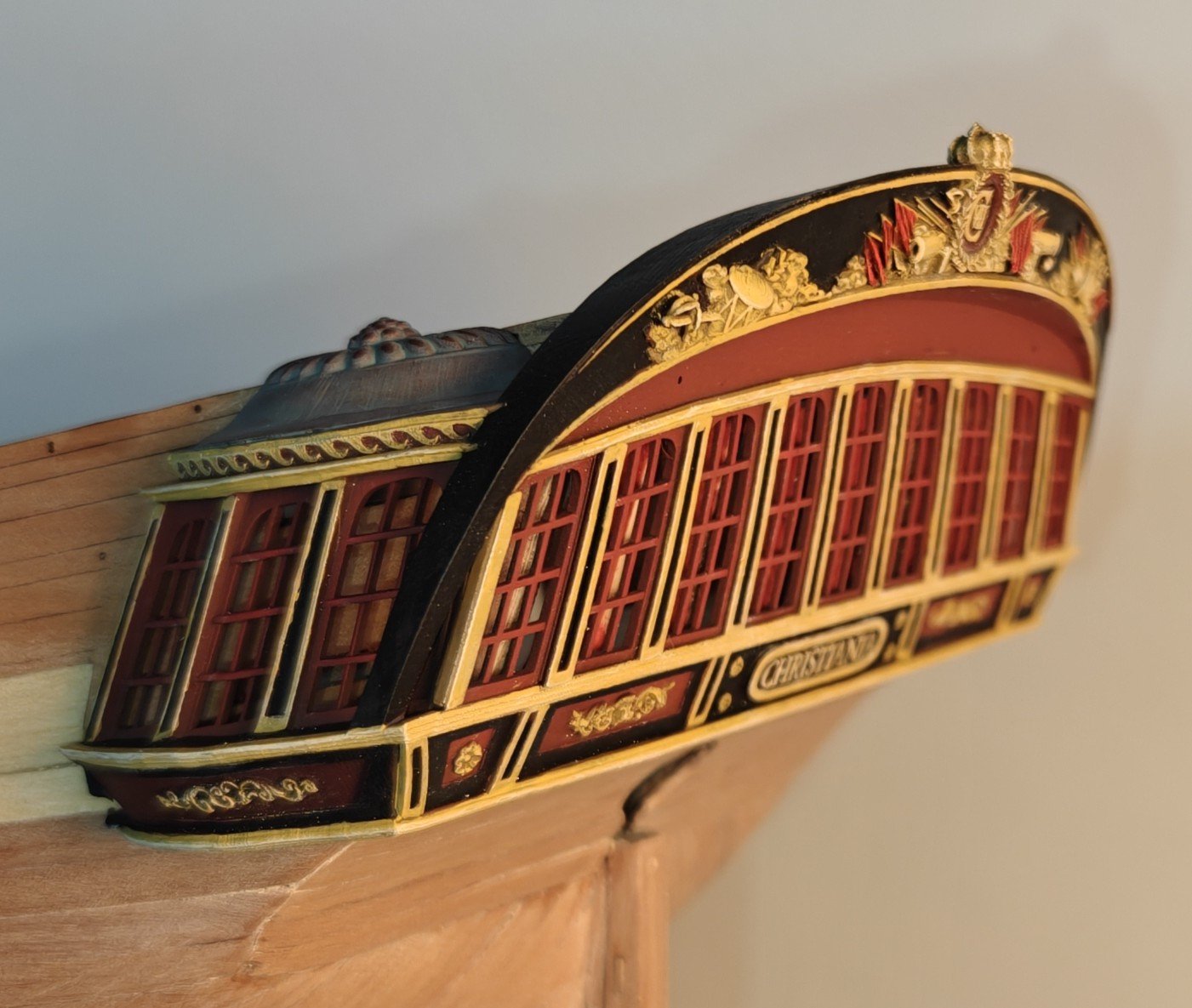
Log entry 37 - and now adding colour.... Time for a proper update - lot's of pictures as a lot has happened visually! I added the wale on the other side and sanded it flush with the planking at the bottom like the first side. Then the whole hull was sanded down to 400 grit and varnished (and sanded and varnished and sanded again...). Then I formed the prow decorative strips: (The Bulbasaur sock is for wiping sanding dust off the hull... 😅) After this, I painted the upper bulwarks. It's the same pattern as in the Sphinx manual, but exchanging the blue for black. And then I could attach my newly widowed stern! Here's a bunch of images of the current state. I am very happy with the looks overall! On a side note, the two new officers has, at least for now, replaced Kaptajn Hornblæser, who met with an unfortunate accident which caused the loss of his sword... (I had base coated him, and he tumbled from the table as I took a step and hit the floor right where my foot came down 0.3 sec later... ) They are cretated with Meshy AI, and actually based on images created with ChatGPT! So fully AI generated. It works very well at this scale and even holds up fine at 1:32, here's some images at that 'double scale' (There is a mis-print og the right officer's left hand - bad supports during printing). Now I will paint the decorations the same yellow I used for the stern - I think that will give a coherent and realistic look, compared to the unpainted pear. BR TJM


- 148 replies
-
- 14
-

-

-
- Christiania
- Vanguard Models
- (and 1 more)
-
Actually, scratch that. I made a test on a spare print and it seemed to work well enough. So I went ahead with the painted version. Of course it did not go quite as smoothly the second time around, but it will be good enough. I did get a few scratches but nothing too bad. I would probably regret it if I didn't make a try and I think this will do.

- 148 replies
-
- 7
-
-
- Christiania
- Vanguard Models
- (and 1 more)
-
I am getting close to the point where I have to attach the 3D printed stern. I have been trying out some acetate for window glass, and it is potentially doable, however, I am considering leaving it out. Even at very close range I basically cannot see the glass! I have to make a real effort to see any hint of it at any angle. And I worry that I may mess it up when I have to glue it in. I may not be worth it to try to make it work... Hmmm...
- 148 replies
-
- 3
-
-
- Christiania
- Vanguard Models
- (and 1 more)
-
This is my experience as well - highly recommended!
-
I have seen and tried many alternatives to Meshy, but none currently works as well for the things I have tried. It is amazing that Meshy can take pencil/ink drawings and return naturalistic 3D models!
-
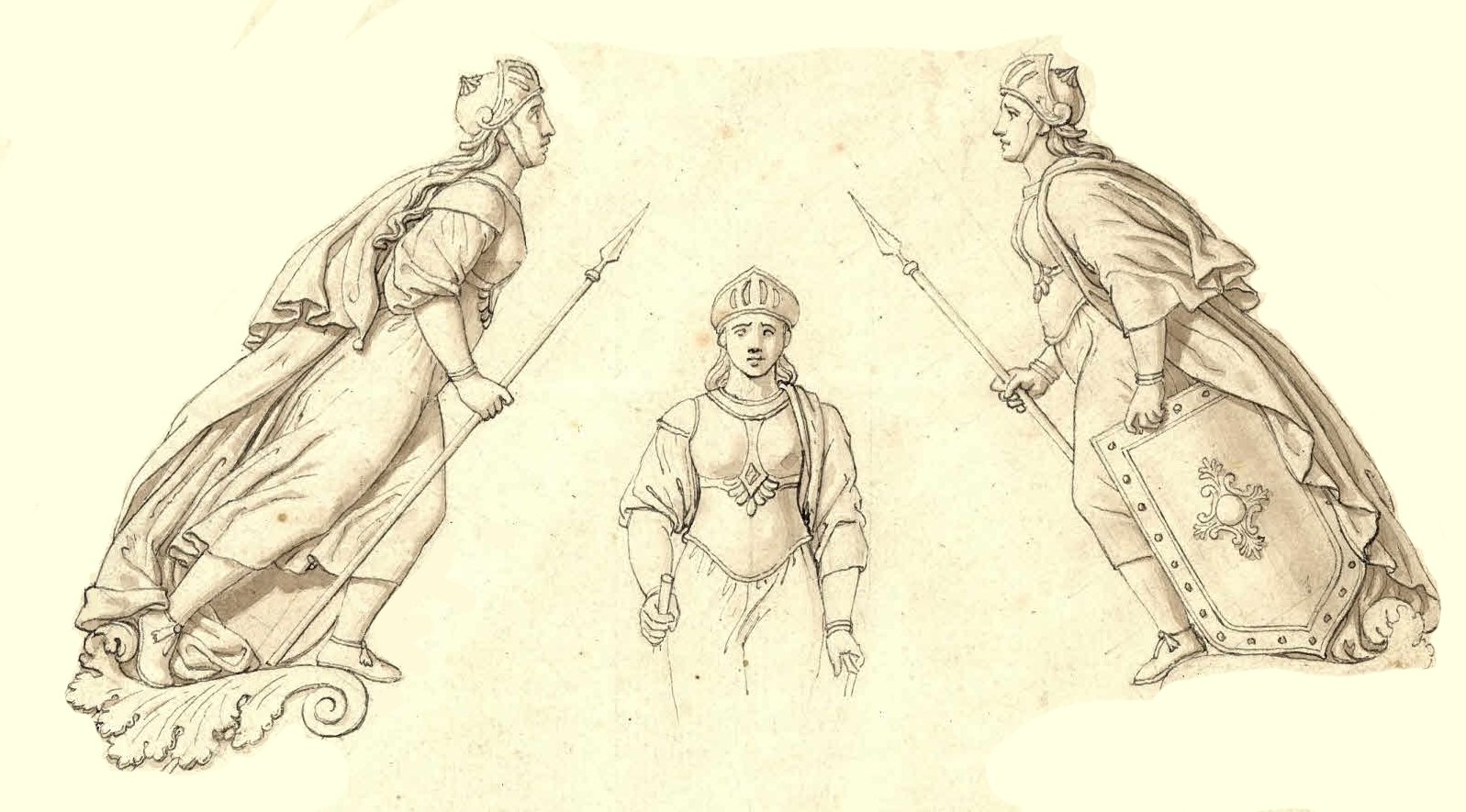
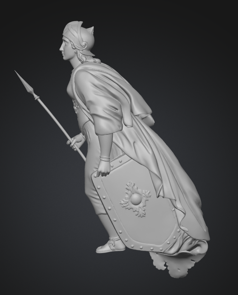
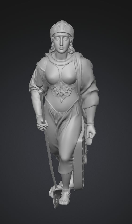
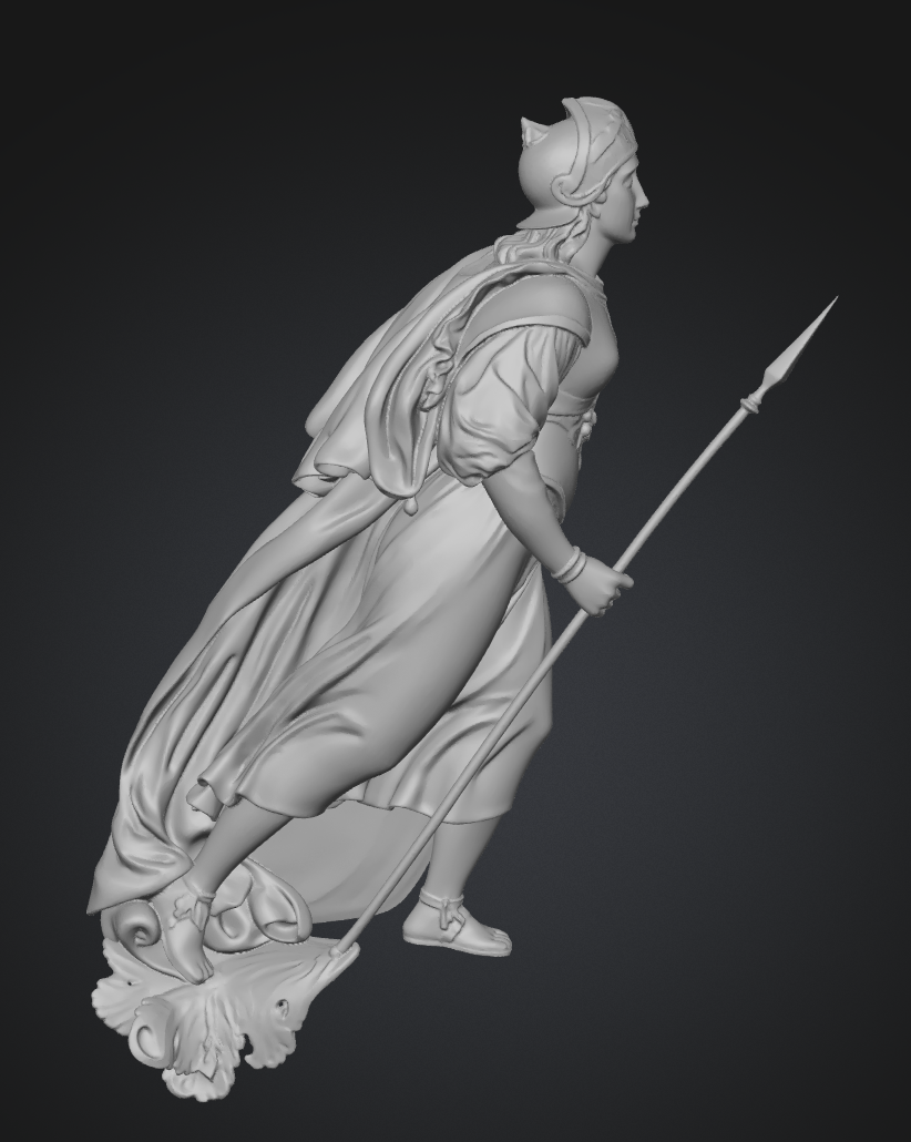
As @Chuck predicted a while back when this tread started, Meshy has now released the beta version of multi view for the Meshy 6 model. And it is fantastic 🙂 Here are the drawings of the figurehead of the frigate Rota from 1822, designed by the famous painter Professor C.W. Eckersberg: Feeding these three views in seperate images to Meshy gave me a near perfect model of the figurehead: So now we don't have to rely on extrapolation if we have several views, either from drawings or from photos from multiple angles 😄 BR TJM

-
Agree, they are very nice.
-
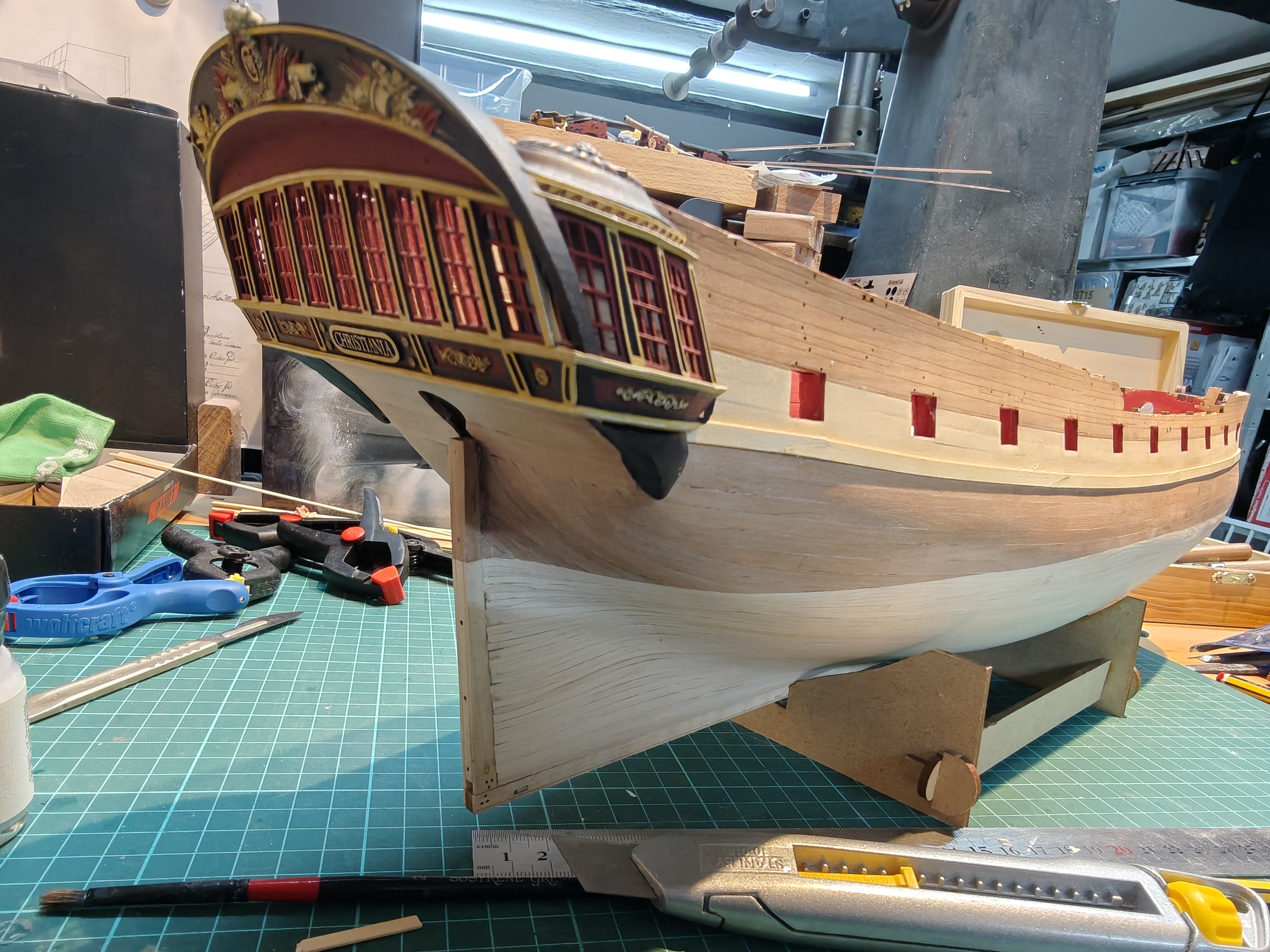
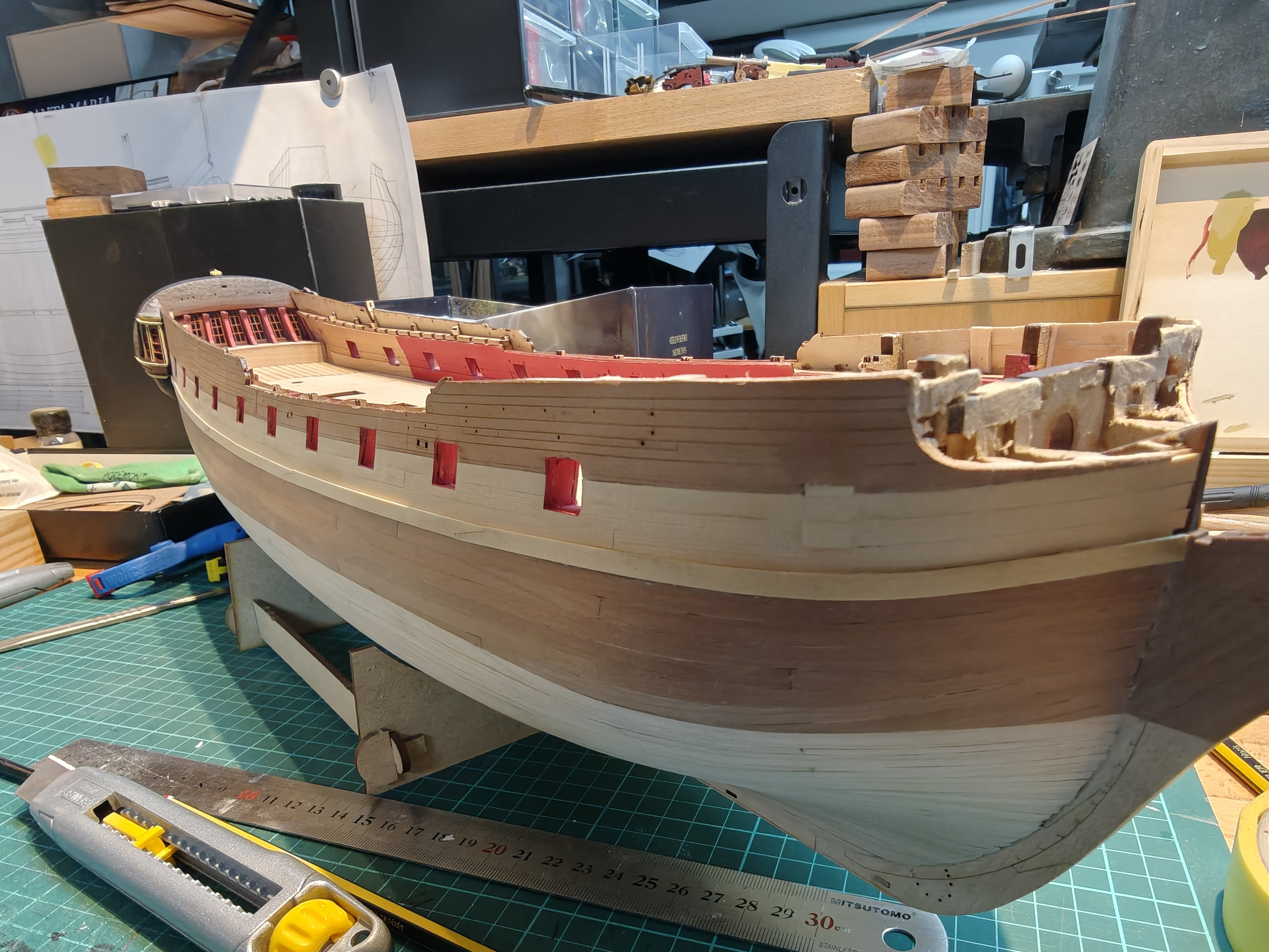
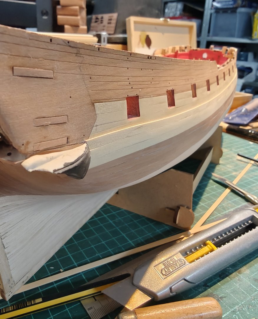
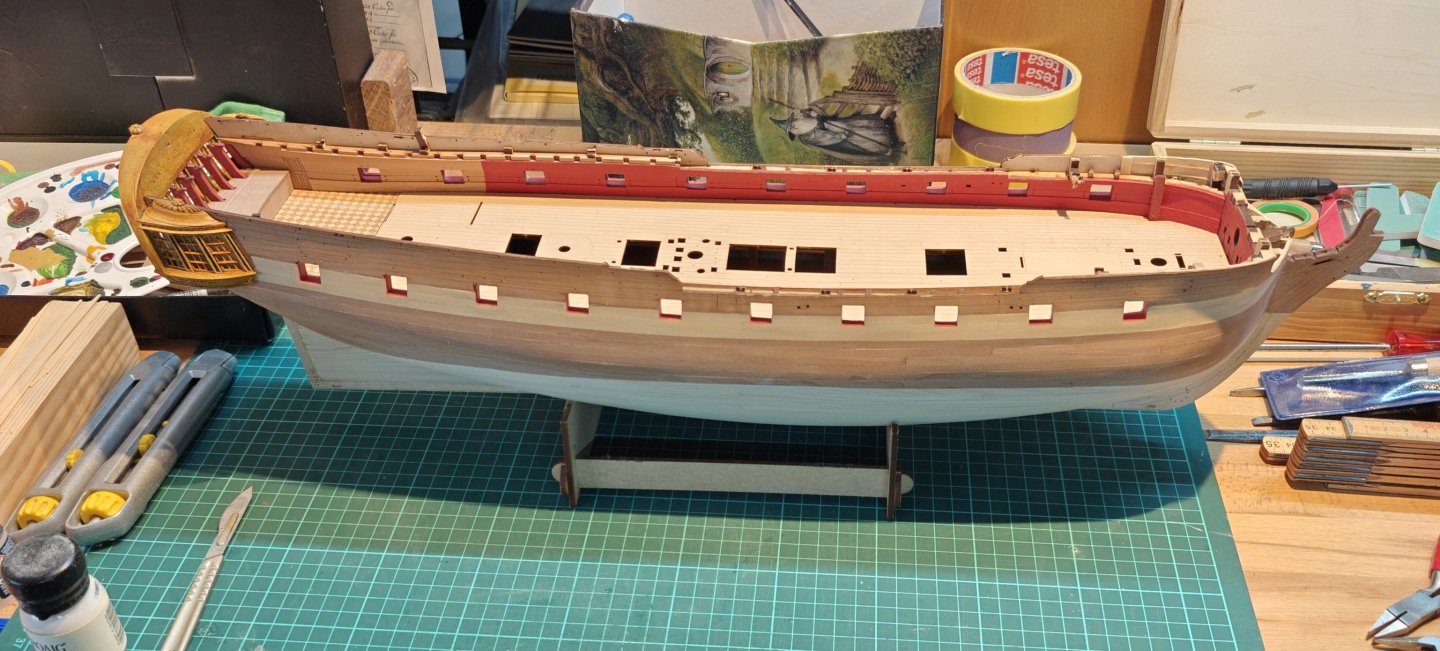
Log entry 36 - starboard wale done I added the two last yellow ceder wale strips (scarfed) and a pear strip (butted) and sanded it to blend into the second planking at the lower edge, while keeping the full 0.8 mm at the upper edge - except at the bow where I took it down to almost nothing. This seems to work well enough, though it would of course have been better to use one layer of 1.6 mm for the planking. The lower blend edge is visible if you look for it, but it disappears at a 50 cm viewing distance. It will have to do. Here's the 'new look': I think I am happy with my decision on how to do the wale and the colours. Still a bit of sanding needed, but I'll pass over the whole hull again after the port side wale has been added. BR TJM


- 148 replies
-
- 8
-
-
- Christiania
- Vanguard Models
- (and 1 more)
-
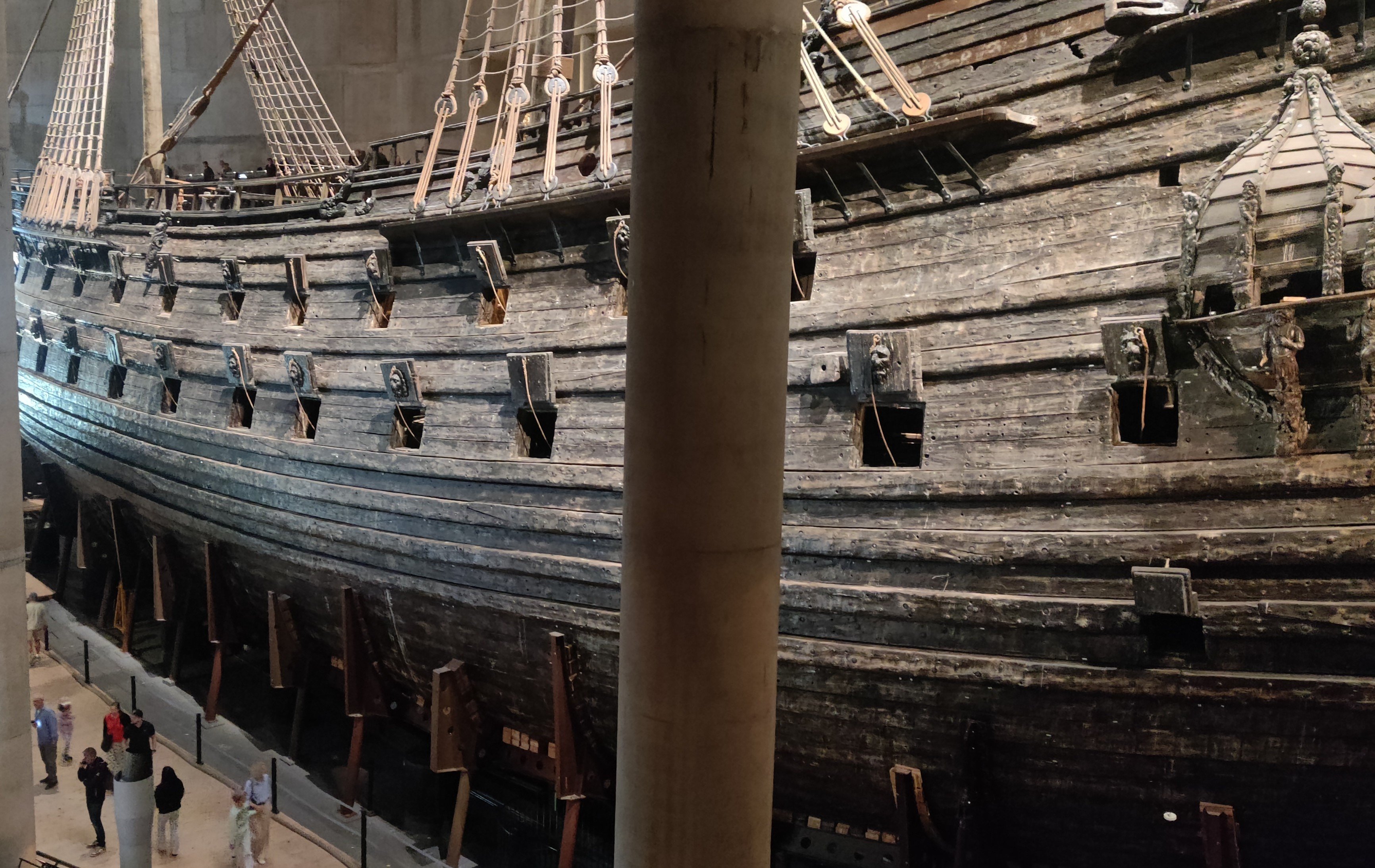
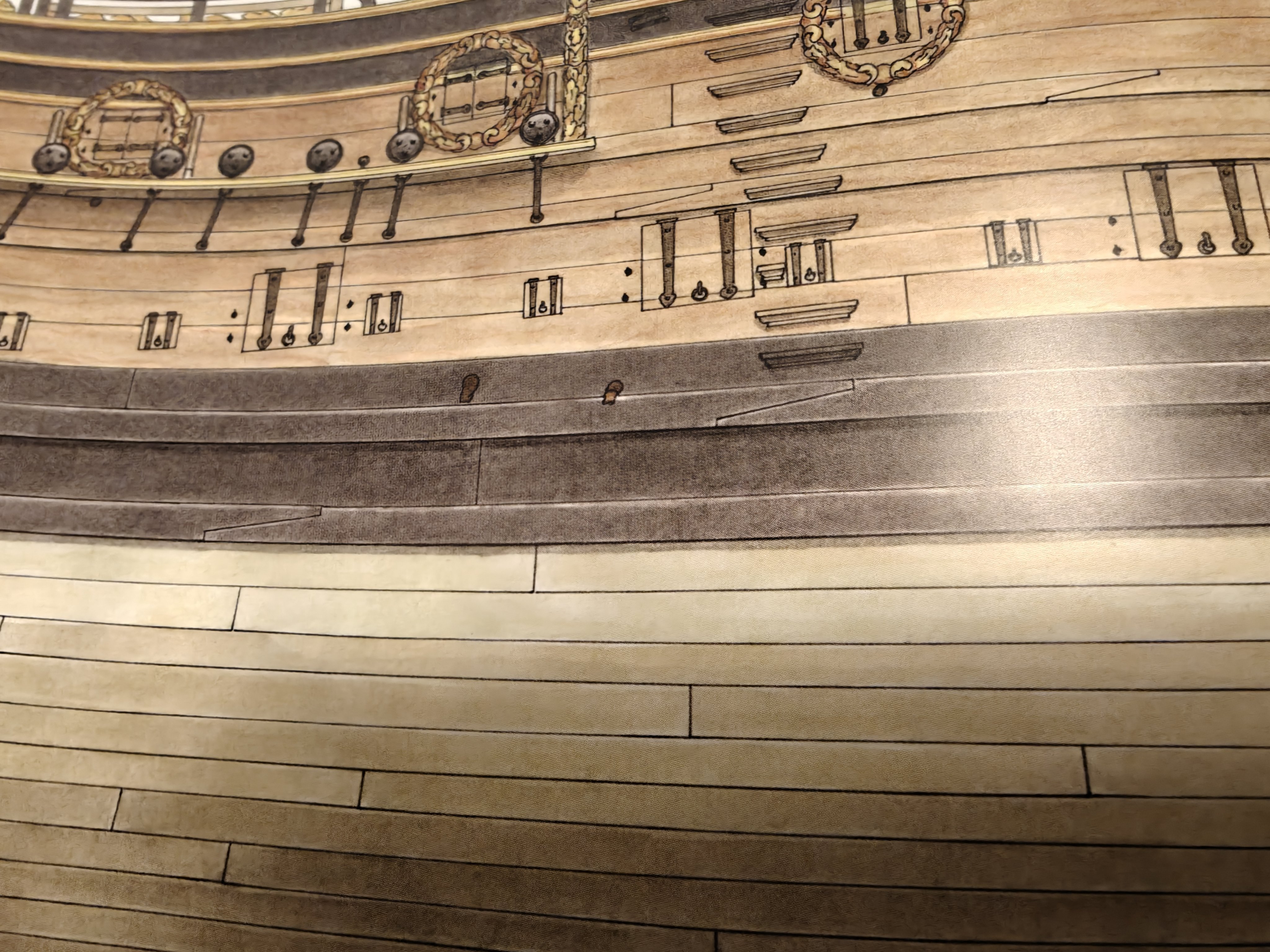
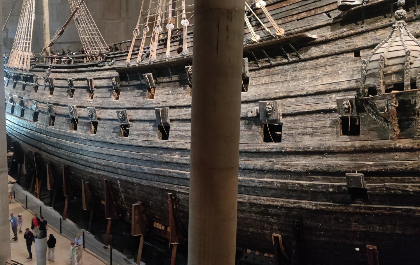
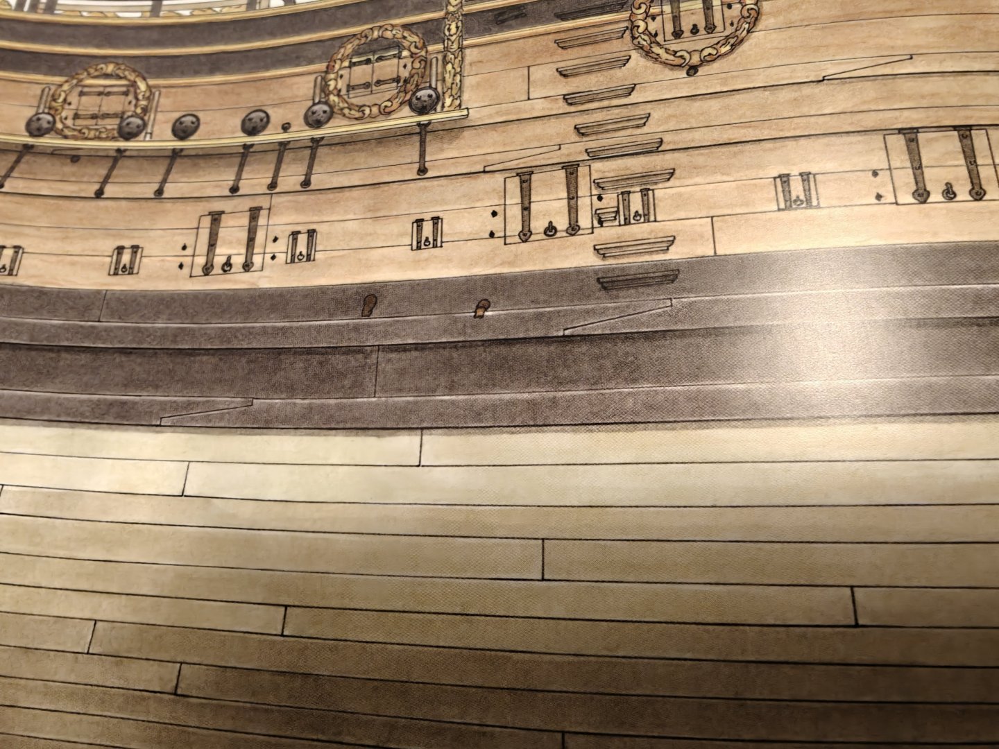
I am by no means any sort of expert, but it is my understanding that the wales are there to prevent sagging of the gundeck, and perhaps also stiffen the hull to prevent keel breaking. Having butt joints would, I think, largely remove the lateral strength, while the scarf joints allows the sections of the wale planks to pass load to the neighboring sections. If anyone has a better, or different explanation, I would welcome the input! It is well documented that the thicker wale planks were scarf joined: Here is a shot of Vasa showing this: And here is a drawing by Richard Endsor of HMS Tyger: And here is a model of Bornholm at Krigsmuseet in Copenhagen (that I use for a lot of the colour inspiration for Christiania), showing scarfed wales: In general, many models at Krigsmuseet show this for the wales - but some don't. There are also sources that does not show scarfed wales, like Boudriot's the 74 gun ship. Here the 'thick stuff' is made of longer sections ot seems, but are still shown as butt joined.
- 148 replies
-
- 6
-
-

-
- Christiania
- Vanguard Models
- (and 1 more)
-
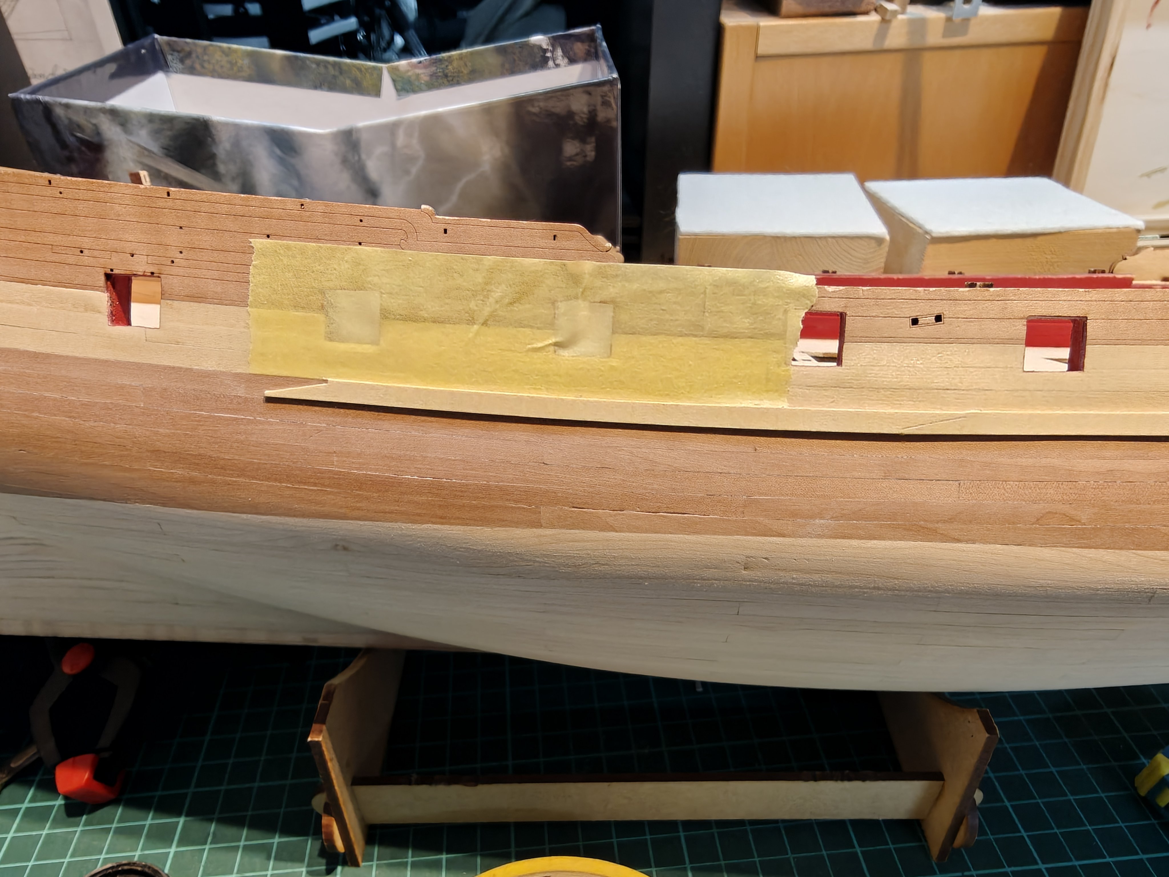
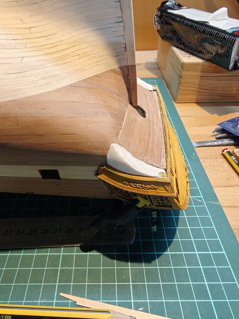
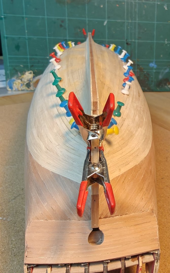
Log entry 35 - lower gallery parts and starting on the wales I was not happy with my wooden gallery bottom, so I though I would try sculping it from polymer clay (Fimo). I was able to get a better fit and sharper edges, so I went forward with this solution. I painted them black and attached them with CA: Don't worry about the nasty gaps between the wood and the clay, it will be covered up by a decorative element that I will probably design and 3D print, to match the rest of the stern decorations. The reason I am gluing thes on now is that I want the wale planks to be completely snug against them, so this is needed to move on with the wales. I have decided to plank with 3 yellow ceder planks and then one or two pear planks and then leave the ridge at the top and (almost?) blend it into the planking at the bottom. The pear wood is then where the hull would have been painted black, giving a compromise between showing as much wood as possible, while still showing the pattern the paint would have given the hull. To make it more interesting (and realistic) I am doing the the wale planks with simple scarf joints, instead of butt joints: The scarfs will be very subtle once sanded, as there is very little grain or colour variation in the ceder strips, but I think it is a nice small addition. They are not too difficult to make. I couldn't resist popping on the painted stern to see how it would look (and check the fit, which is good!): Will be back with more wale planking soon 😁 BR TJM


- 148 replies
-
- 9
-
-
- Christiania
- Vanguard Models
- (and 1 more)
-
Fantastic carvings Matthias, as always really well done!
-
Nice deal! It is unlimited downloads, yes, but a fixed number of tokens per month to use. You get 1000 tokens, enough for 50 meshy 6 runs. For each run, you can re-run the prompt 4 times (so 5 total) and download all of them to have something to chose from.
-
Thanks you so much, guys! Really appreciate the feedback 😃 Yes, I believe I will be going the scratch route for most future builds. But I still have much to learn from this kit, but I feel that every time I complete a phase, I would be able to use that on a scratch build - I did not have confidence like that after Flirt, I needed more experience. I will be sorely tempted by Vanguard Models' future releases - while both Surprise and Agamemnon will be fantastic, I am really looking forward to see Chris do HMS Tyger. The ships from the period 1640-1690 has a wonderful aesthetic, I think, and I really want to see what a modern, full-blown VM treatment will look like. Luckily for me, that one is still a bit into the future! I also have Amati's Revenge 1577 stacked away (also designed by Chris Watton) and I plan to do this some day, but not sure when.
- 148 replies
-
- 2
-
-
- Christiania
- Vanguard Models
- (and 1 more)
-
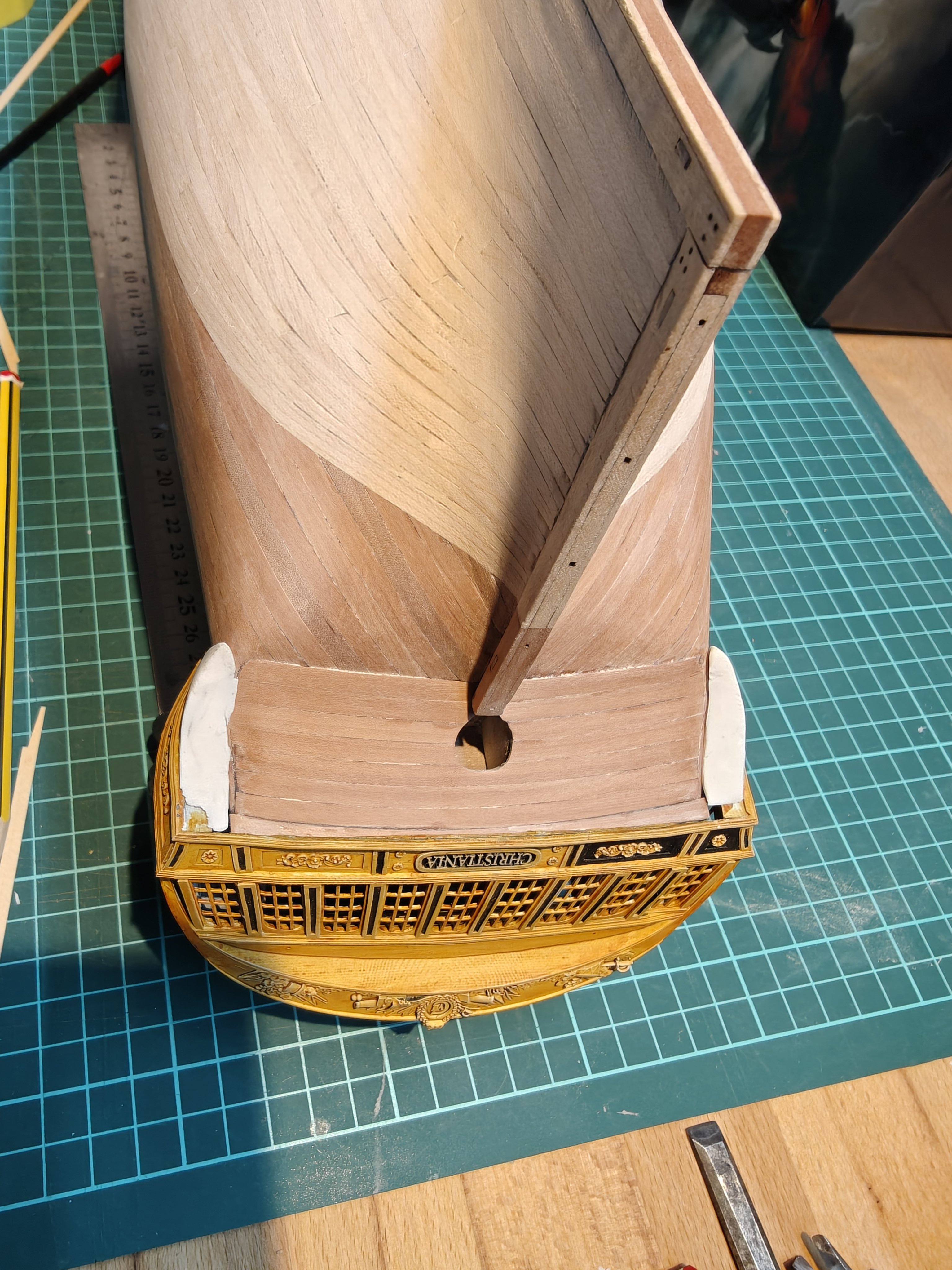
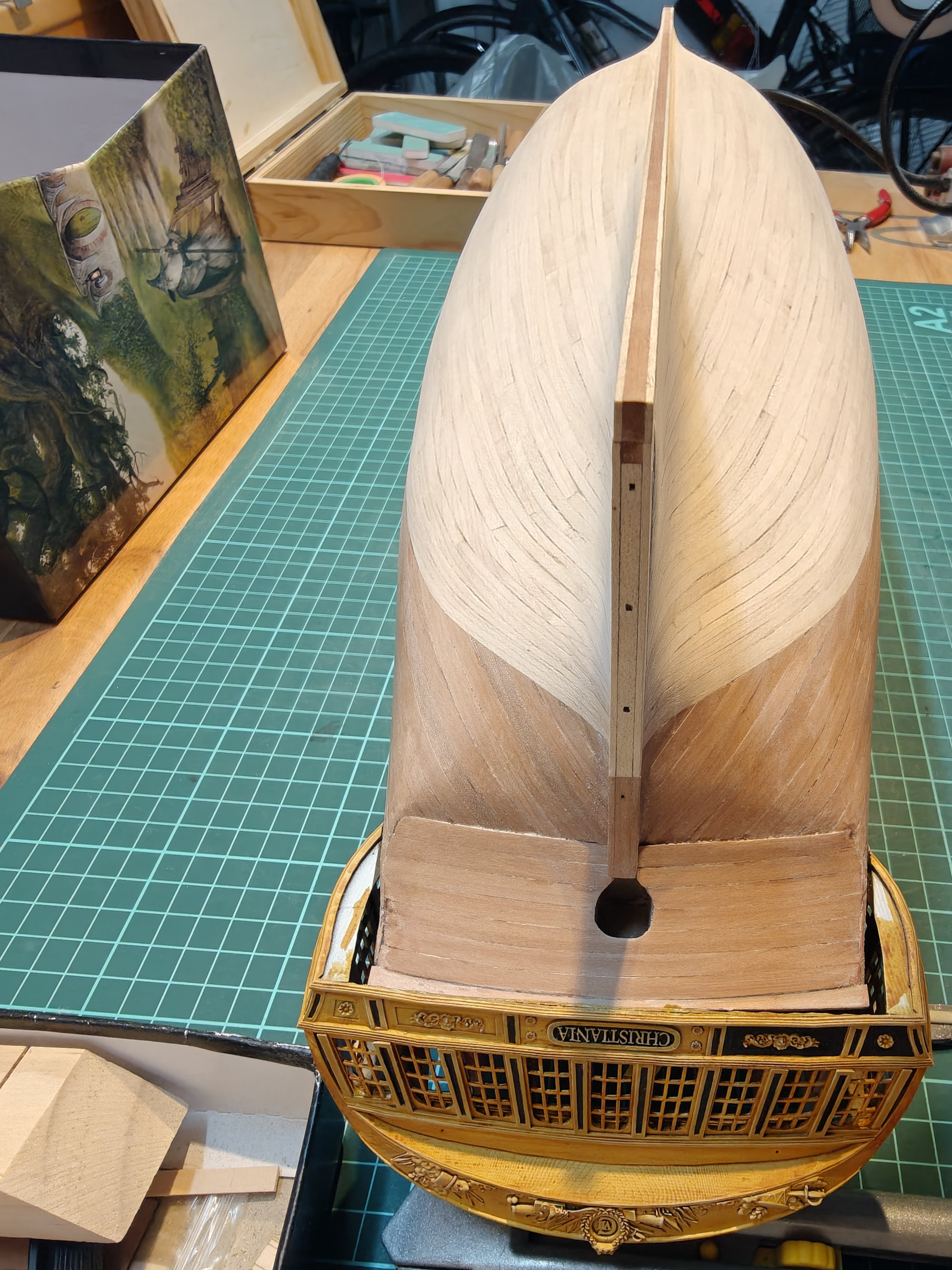
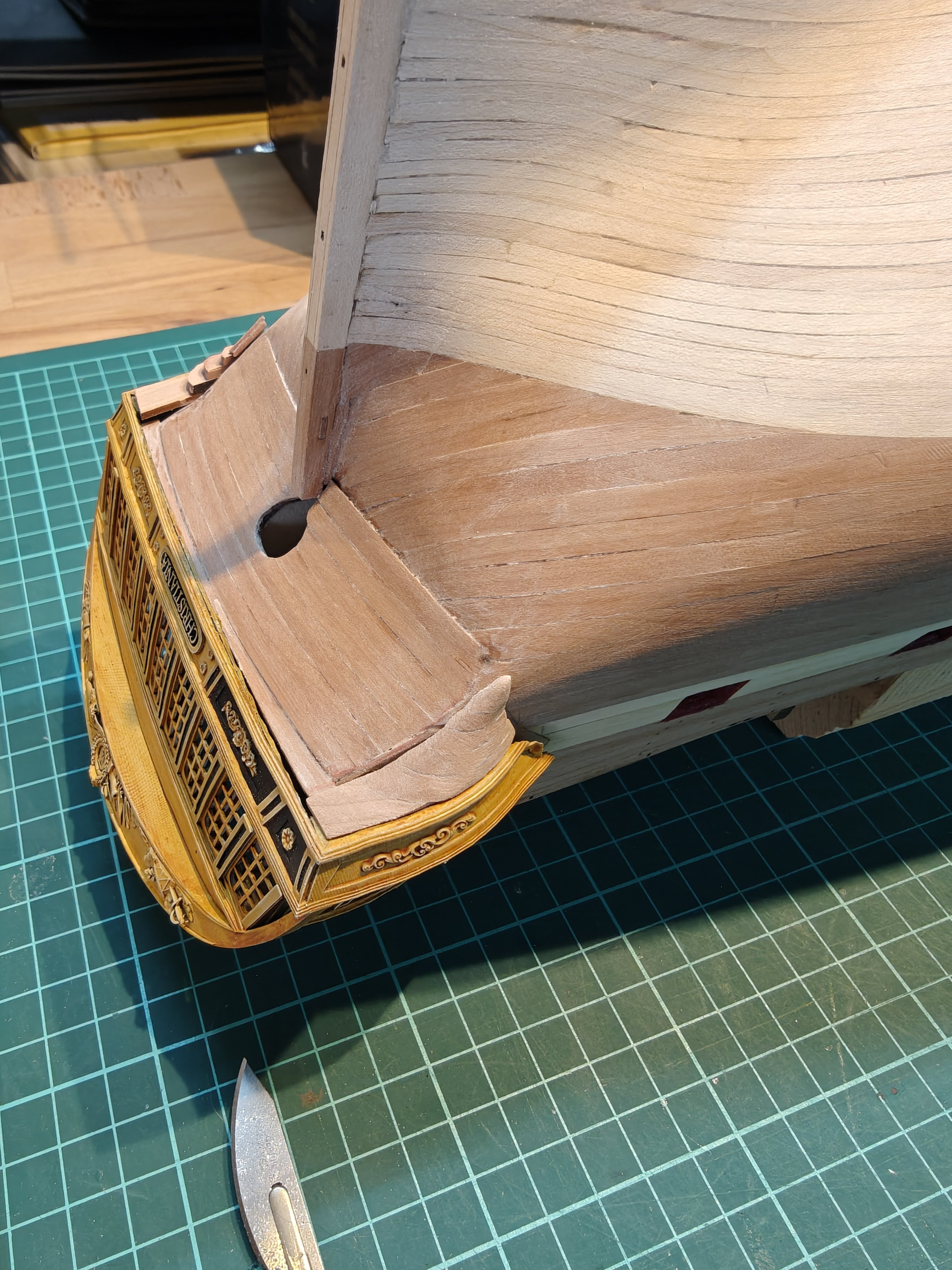
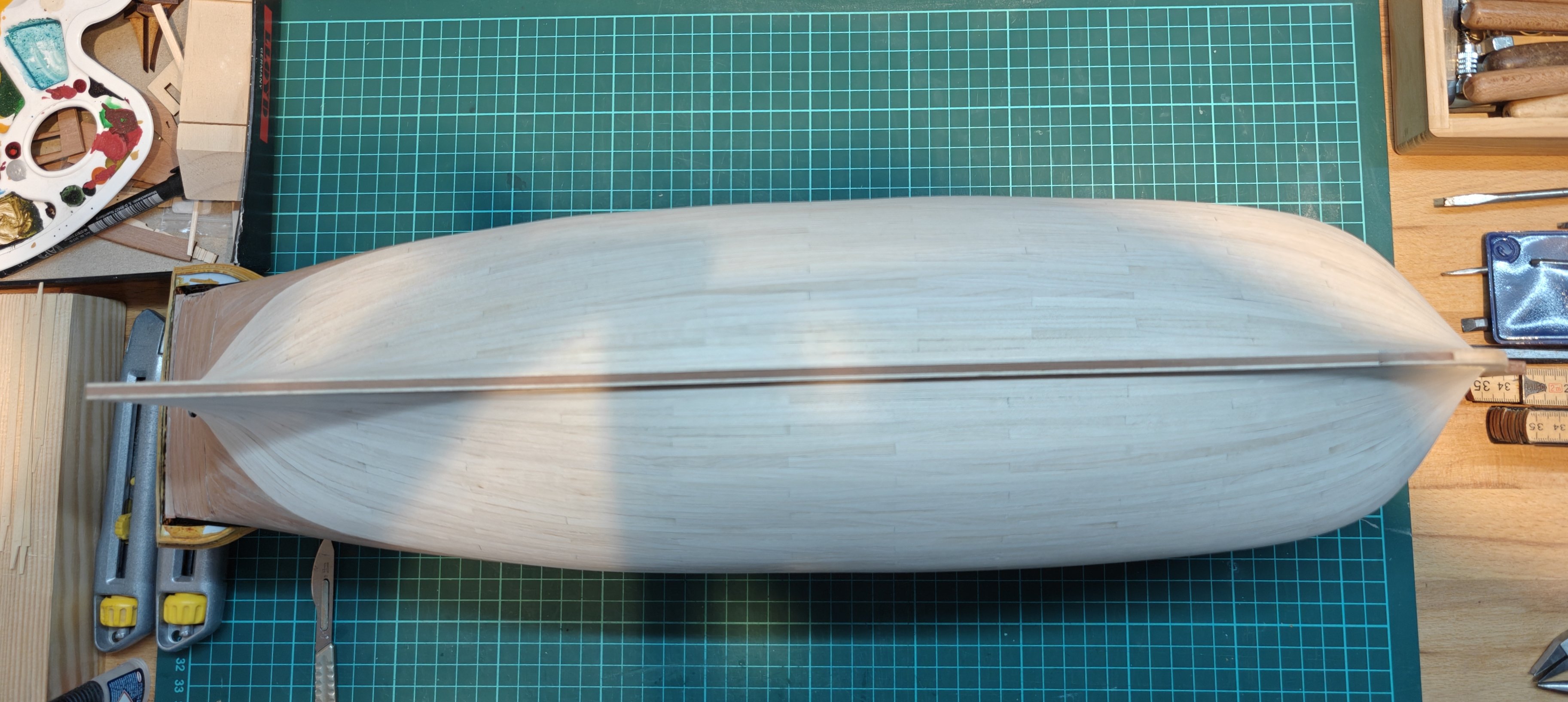
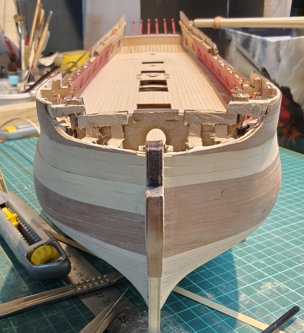
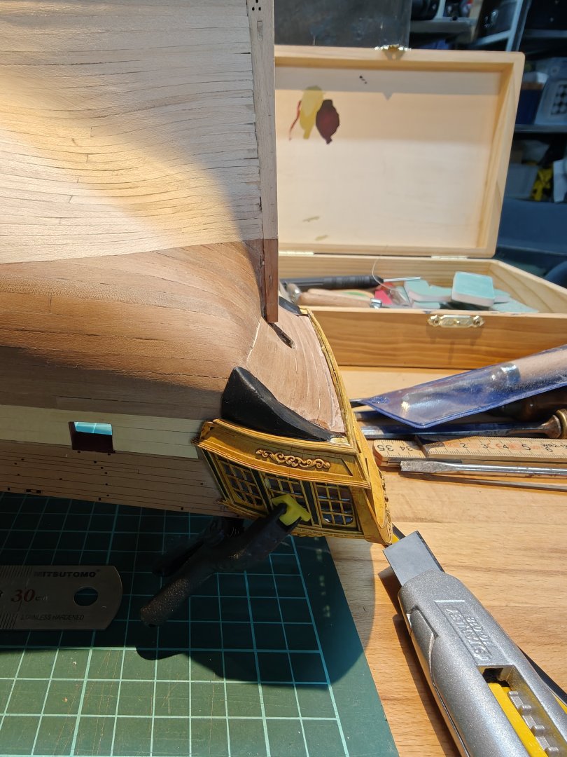
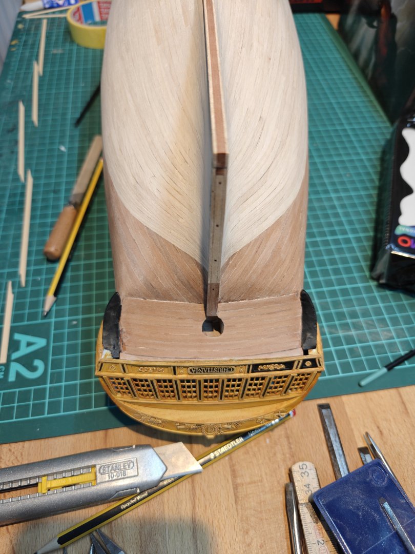
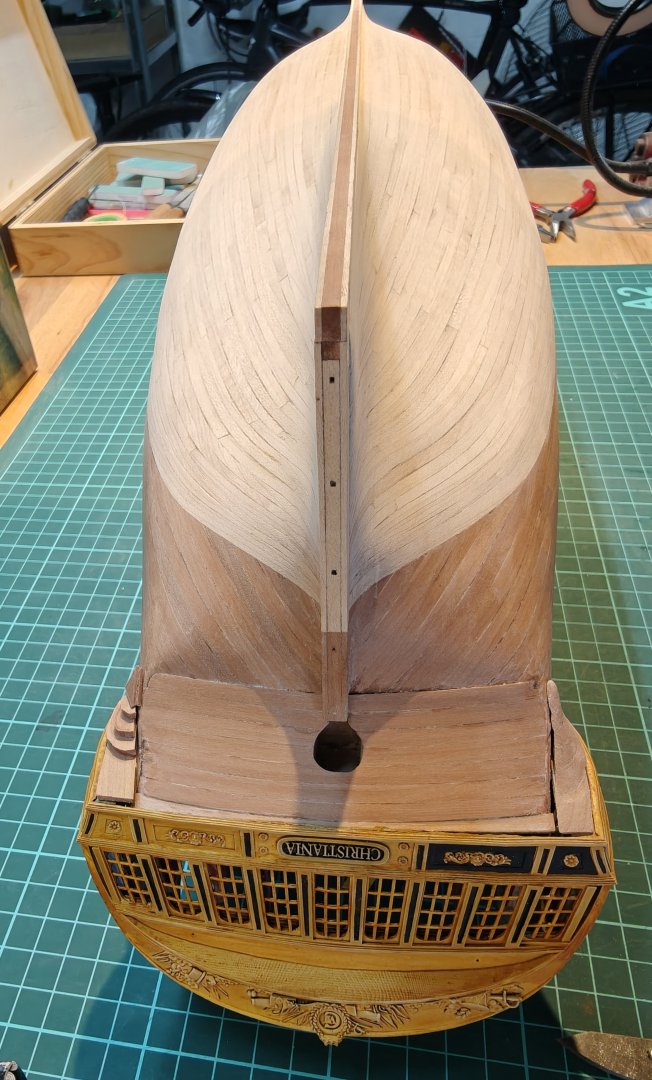
Log entry 34 - planking completed! And, just like that, the planking is complete! I have done the first sanding pass, and it is mostly good, just a few spots that need a bit more: This has taking me a very long time - almost 16 months since i began the second layer planking. Most of that time was obviously not spent on the model, ad I have been procrastinating by making Elben and drawing other ships i CAD, i have learned 3D printing and I have modelled the stern, the figurehead, a ship boat, many different cannons, etc. I am happy I pushed to the planking finish line, as I look very much forward to the next stage of the build. I am planning the wale planking and I am modelling the lower galleries - this is also why I have loosely fitted a reject stern print, as I need it to fit the lower gallery parts: It needs a bit more work, but I will be filing the gap with filler and covering it with a decorative element. And then the workspace got that cleaning 😅. BR TJM


- 148 replies
-
- 11
-
-
- Christiania
- Vanguard Models
- (and 1 more)
-
Only 6 planks missing now! Then a bit of gap repair in a few spots and then a lot of sanding. (And a workbench cleanup! 🤪)

- 148 replies
-
- 10
-
-
- Christiania
- Vanguard Models
- (and 1 more)
-
I also think what you have looks very good. I see the point of the end grain - a miter connection would have been ideal I guess, but personally, I would be happy with the joint you have. I like the wood look, as long as it does not have obvious laser char, but you always take care to remove this so all good! Whatever you go for, it will look great 😄
-
Nice! Do you always brush it on, also on the large surfaces like the main hull, or do you ever use an airbrush? Also, what varnish are you using? It looks great!
-
Yes, this is also what I conclude based on the evidence I have seen so far. And yes, no matter what, this build will not be a truly faithful representation of Christiania - it cannot be with me adapting the Sphinx kit. All of the deck furnishings will be 1:1 the Sphinx setup. So I guess I can take the liberties I want, but I still have to decide what I prefer 😅 The comment about the painting of the ships comes from Danske Orlogsskibe 1690-1860 (a fantastic book!): This translates to: In Gerner’s period, the painting of ships was introduced in the Danish navy. This came about almost through a private initiative, as the commander of Sophia Frederica in 1781, A. F. Moltke (1748–1820), at his own expense had his ship painted. The following year, the commander of the Indfødsretten, in connection with sailing to the Mediterranean, requested permission to do the same. The commander of Holmen had now come to the conclusion that painting was more preservative than the ordinary tallowing that had previously been used, and therefore had the painting of all Danish ships of the line carried out.¹¹ Previously, the ships had been “blacked” with a mixture of thin tar and soot, something that gave the ships a dark brown, almost blackish appearance. According to the regulations, this applied only to ships of the line, while the frigates were occasionally treated with pine pitch. When the blacking and pitch-coating took place, care was taken to cover tarpaulins over the “externally painted ship ornaments” in order to avoid blackening them.¹² Reference 11 is to a text by F.C.Kaas published posthumously in 1843 who recounts the work that was done while he was Chief of Holmen (the Navy shipyard in Copenhagen) from 1781-92

- 148 replies
-
- 1
-
-
- Christiania
- Vanguard Models
- (and 1 more)
-
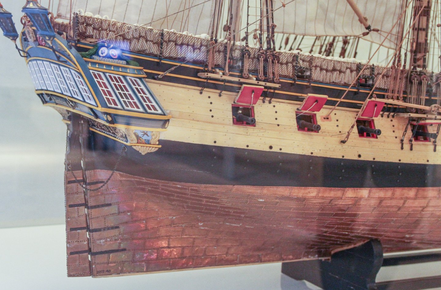
I think this contemporary model of Fyen (1736) shows how it would have been. Even if it is some 40 years earlier than Christiania: We know that the ships were not painted between the upper decoration and the lower wale until sometime in Gerner's period, so after Christiania was built - I did not know this when I decided to emulate the painted yellow band with the cedar. This is why I am now considering making it the main 'wood' colour for the hull instead, by using it for the wale as well.


- 148 replies
-
- 6
-
-
- Christiania
- Vanguard Models
- (and 1 more)
-
@Arthur Goulart, thanks for the suggestion - in fact this issue had been increasingly been bugging me lately. My original plan was to have a colour scheme like this: This looks like two thin wales, painted black, which was the norm up until at least the 1720's or 30's. But i have become aware of the way the wales were made later in the 18th century that you point out, and it makes it difficult to decide what to do colour wise. As mentioned in this post, I am not sure I like the look if I continued the yellow cedar on the wale part. Though that may be the more realistic option! This is also the way the model of Gerner's Bornholm is depicted: However, I would like to keep as much of the hull natural wood as possible, so I would like to avoid painting the area between the wale and the waterline black, though this would probably be the most realistic. Instead I looked towards another model, of the hukkert Amager: This shows the black double wale, it is a ship by Krabbe like Christiania and the original drawing shows the same wale, blended into the planking: But I admit that I am not being consistent here, and that balancing the historical accuracy with the wish to show as much wood as possible is getting me into trouble! I am seeing a number of options here: 1) continue as planned, two thin wales painted black. It will look good, but will not be accurate for the time period - a bit of a pitty! 2) add three wale stakes in pear and blend it into the hull, no black paint at all. I think this may look a bit unfinished? And it might be difficult to get a nice transition when blending the lower part - I could leave a smaller ridge there as an easier transition. 3) add two or 3 yellow ceder and one pear plank as wale, and blend it into the hull. This would have the pear represent the part that is painted black, between the wale on many several depictions, incl. the Bornholm model. 4) build the whale from yellow cedar, blend it into the hull, and paint the area between the main wale snd waterline black. This is probably the most realistic, but it paints over the nicest part of the pear hull planking 😅! And this is what I wanted to avoid! It might have been better if I had planked the upper part either entirely in pear or yellow cedar, but I am not ripping it off now! I will have to find a solution based on wale planking and painting. Any suggestions, both on opinions on the above, or on other suggestions for a solution, would be much appreciated!


- 148 replies
-
- 3
-
-
- Christiania
- Vanguard Models
- (and 1 more)
-
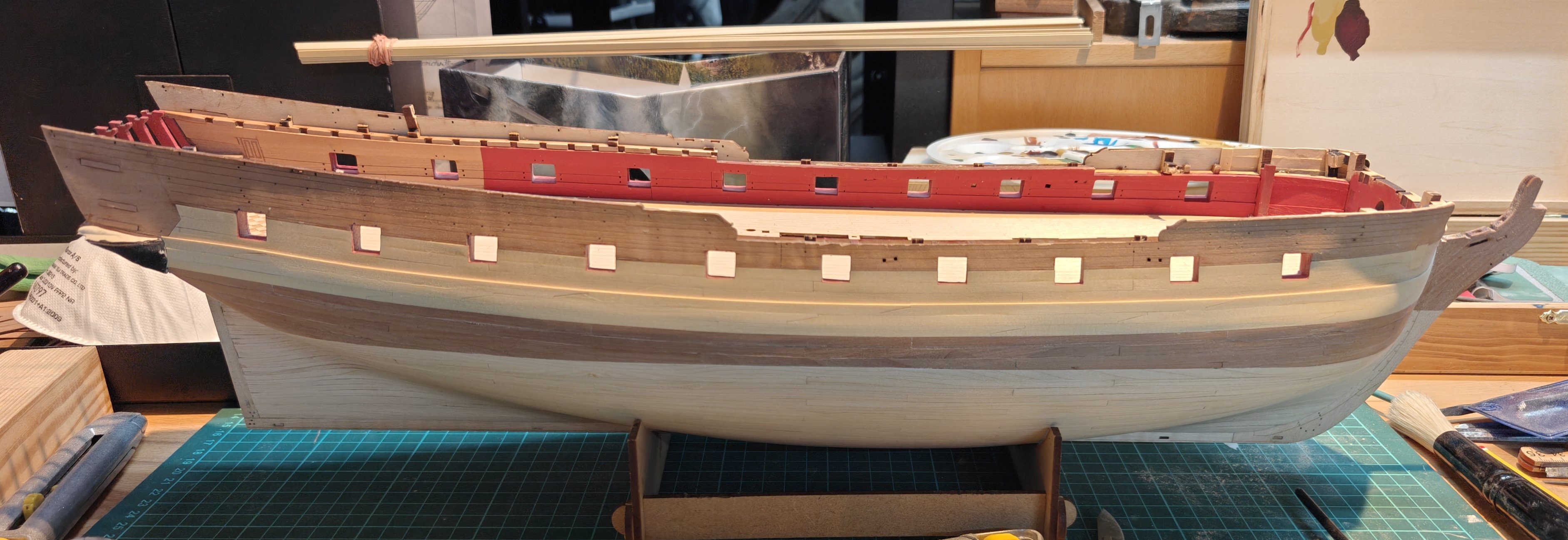
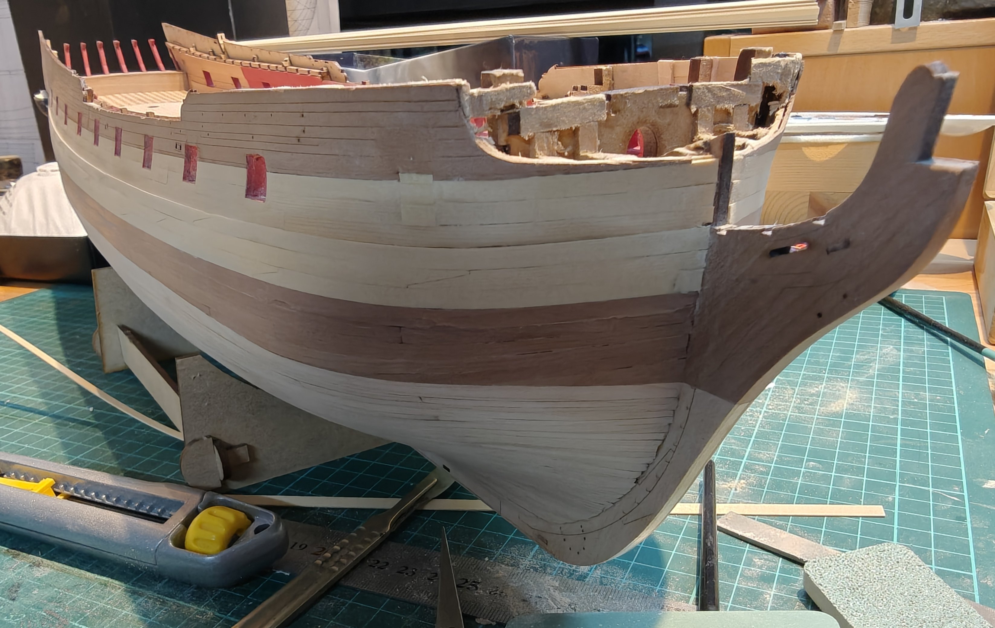
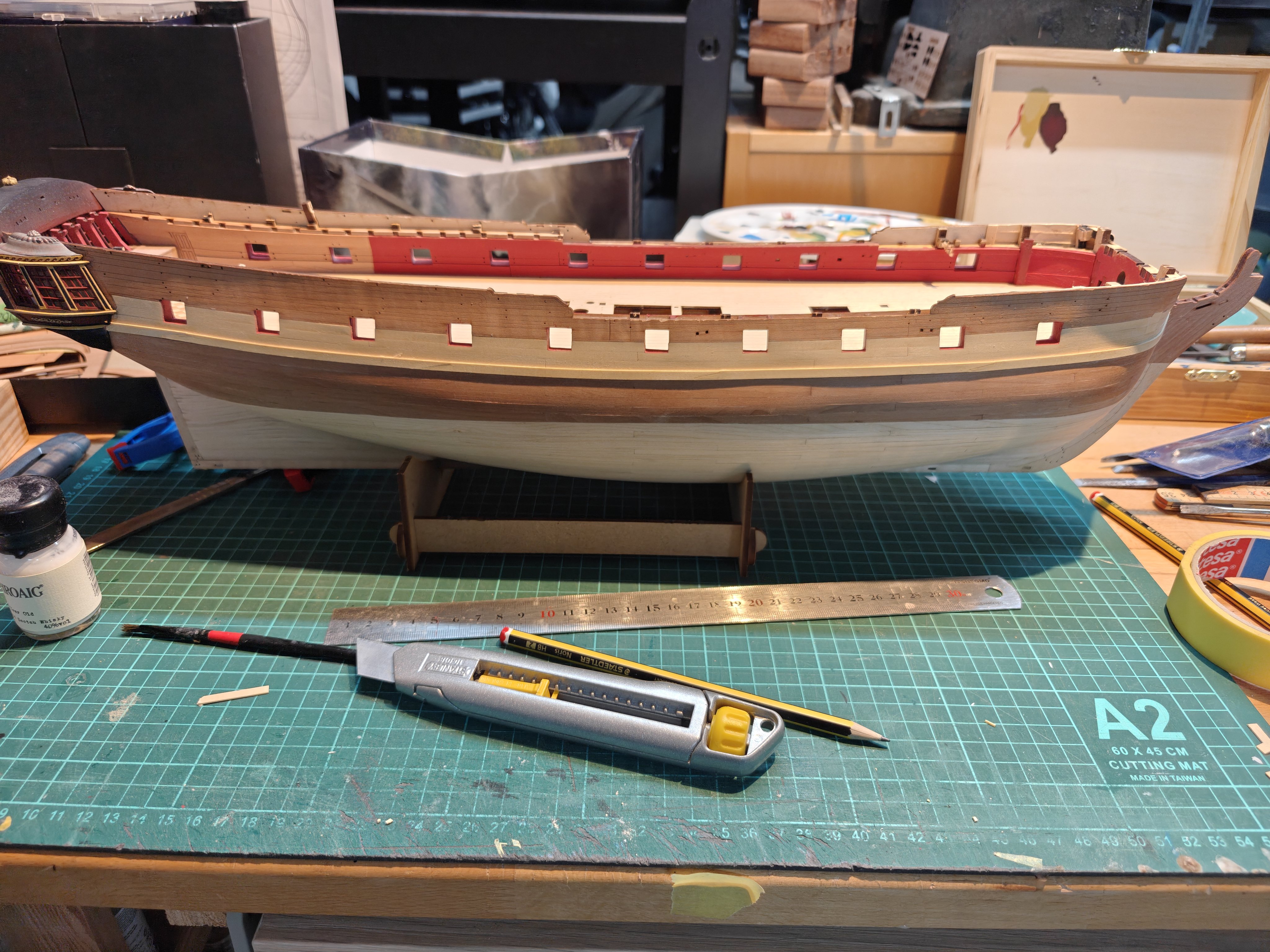
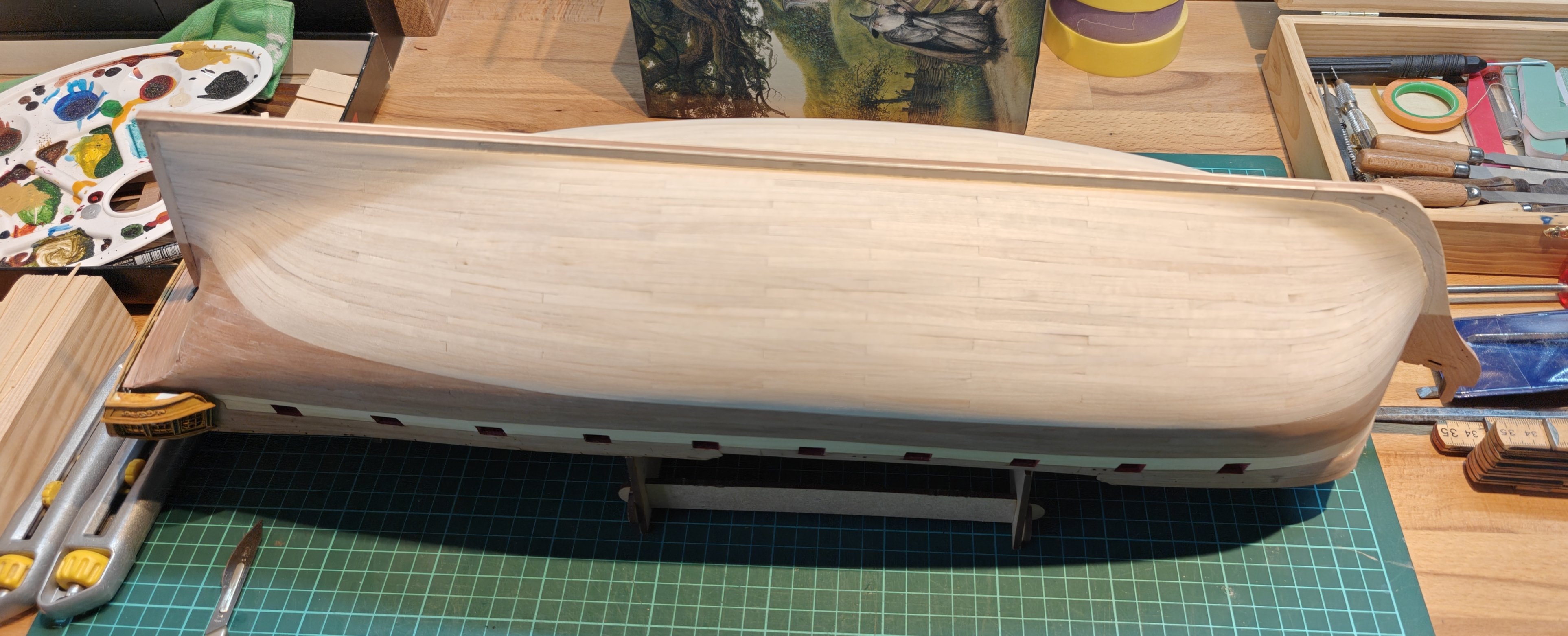
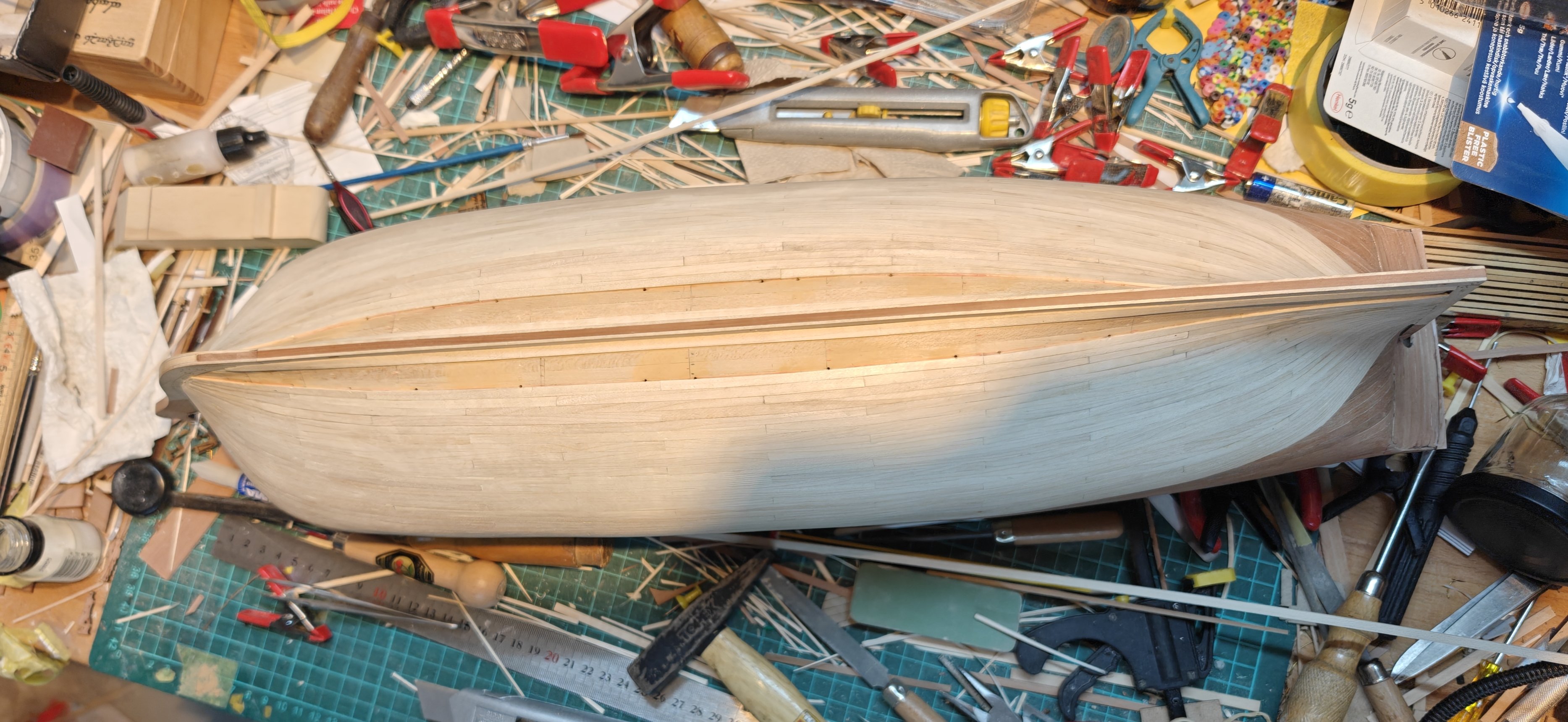
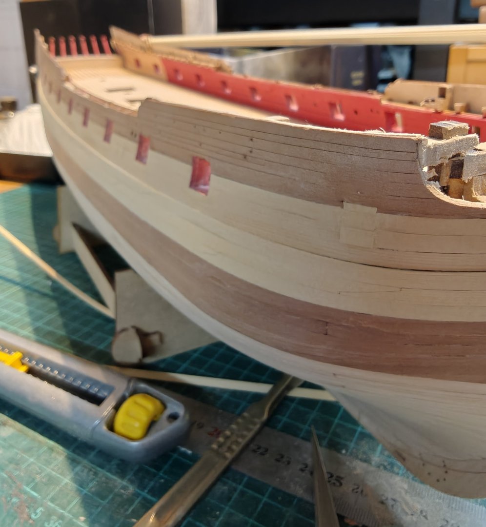
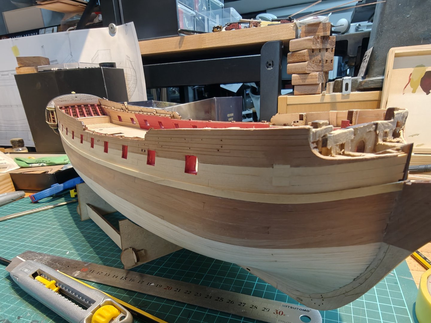
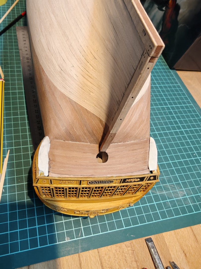
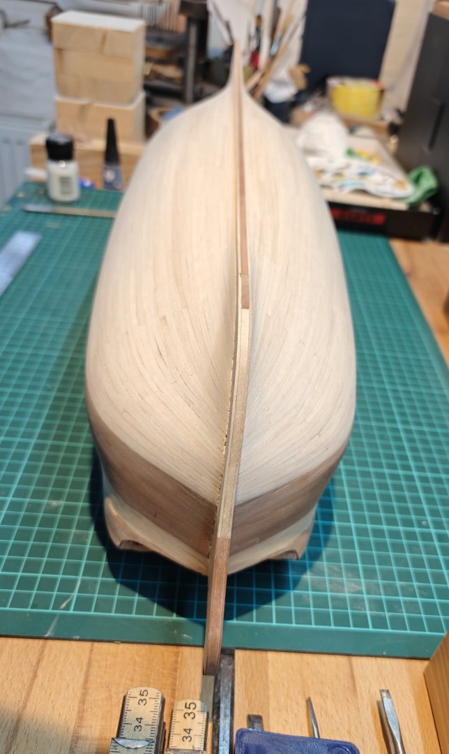
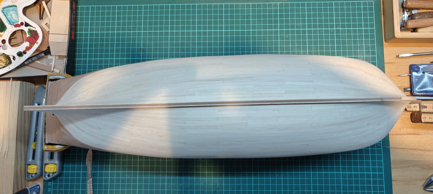
Log entry 33 - planking The second layer of planking is progressing relatively fast, now that I am making an effort to complete it. I am now missing only 7 planks on each side. And the final hull shape is now really starting to appear - the more french-style shape favoured in Denmark at the time is showing well I think. Here's the current status in images, one side have been rough sanded the other is still missing any sanding on the latest 6 planks. And here's a few shots showing the shape of hull: It is nice to see some progress on the build again, I have been procrastinating too long 😅. But now we are moving again! BR TJM


- 148 replies
-
- 9
-
-
- Christiania
- Vanguard Models
- (and 1 more)
-
I am sure you are right! 😅 But thanks, I hope it will turn out good. I think it will, at least from a normal viewing distance. I plan to have it displayed over the stairs, so I won't be able to get too close once it is up. I think it will look all fine from that distance.
- 148 replies
-
- 3
-
-
- Christiania
- Vanguard Models
- (and 1 more)
-
Thanks Ronald! I don't so much mind planking the 'normal' way - I did Elben quite quickly an painlessly. But this one with the weird shapes (my own fault! 🫣) is not that fun!
- 148 replies
-
- 1
-
-
- Christiania
- Vanguard Models
- (and 1 more)
-
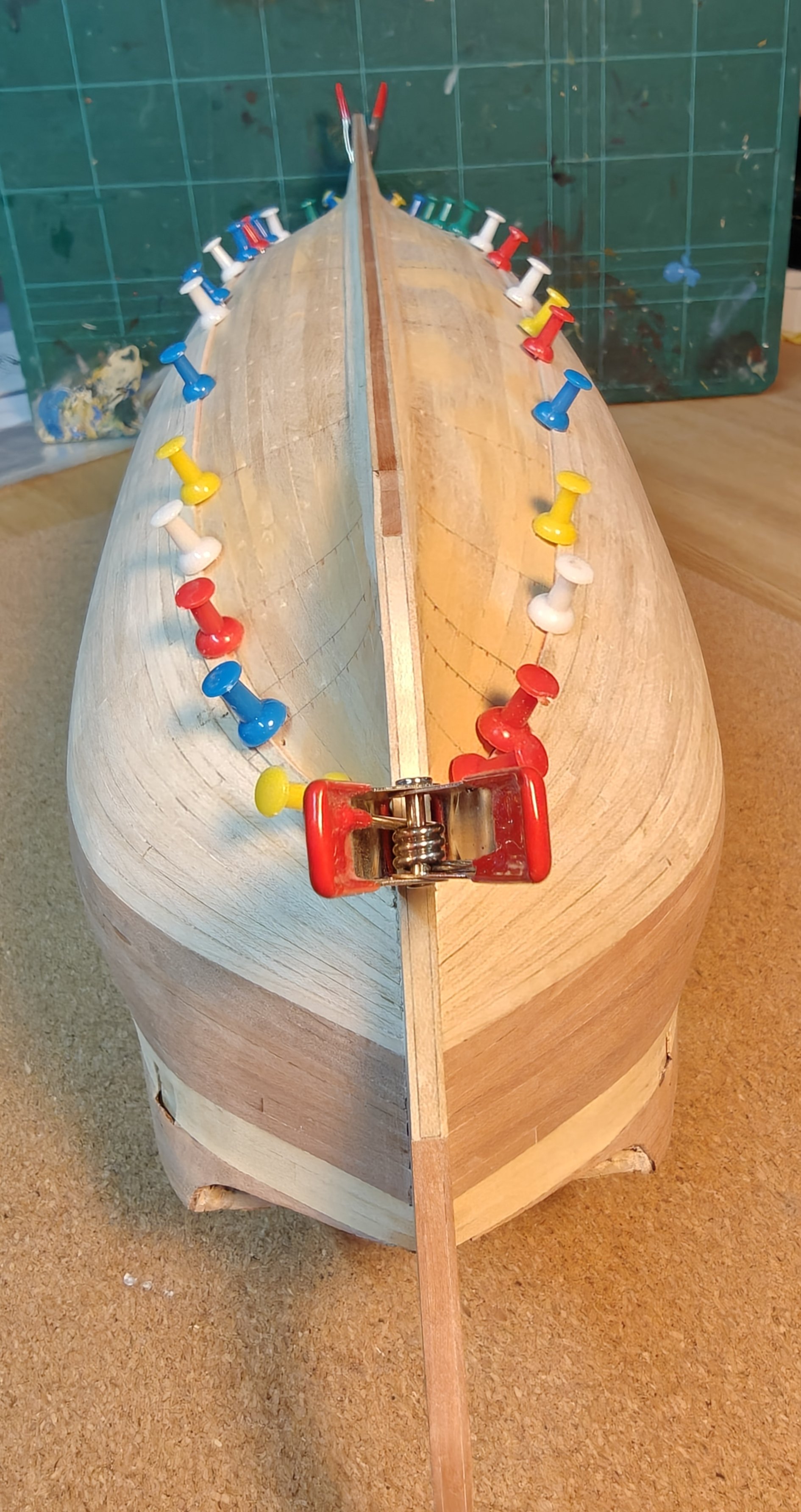
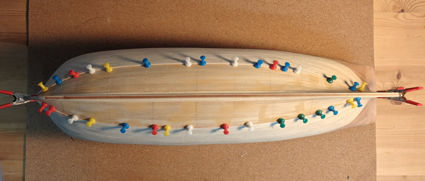
Just a quick update: I have finally managed to move on with the second planking layer. It is a pain to work with the maple and it is extremely time consuming to make the heavy shaping of every single piece of planking, with my silly idea of how to make an 'artistic' all-wood-finish hull below the waterline - this is not something I expect to repeat on future projects 😅. Here's the current state of affairs: 21 planks to go, but they are getting significantly easier now, closer to the keel. I hope to push through in the next couple of weeks snd get the planking completed. BR TJM

- 148 replies
-
- 10
-
-
- Christiania
- Vanguard Models
- (and 1 more)
-
@Waldemar, are you aware of this publication: Ældre danske Metal og Jern Stykker : et Forarbeide til Artilleriets Historie, Otto Blom, 1891 https://www.kb.dk/e-mat/dod/130024096859-color.pdf It is quite a bit later than the previous work we have been discussing by Blom. I have only just found it, but it seems clear to me, that Blom knew very well the difference between the Nuremberg 'talstok' measurements, and the 'nyvægt' (new weight) numbers used in the 1700's. He is in many places cross referencing numbers reported in the old ledgers with those taken of the same pieces in later times, where the measurements were more certain. He can also corroborate this with measurements of pieces that were still in existence in his time. He also references the Swedish drawings and comments on the differences between the numbers where these look strange. I am not saying he did not occasionally draw a wrong conclusion, but it seems unlikely to me, based on this text, that he would have made a systematic error throughout. He was well aware of the different units used etc. Our 42 pounder from earlier is given a treatment in this one as well. Comparing specifically the Swedish drawing and shot weight 😉. BR TJM